WO2013051240A1 - 合成樹脂製の滑り軸受 - Google Patents
合成樹脂製の滑り軸受 Download PDFInfo
- Publication number
- WO2013051240A1 WO2013051240A1 PCT/JP2012/006313 JP2012006313W WO2013051240A1 WO 2013051240 A1 WO2013051240 A1 WO 2013051240A1 JP 2012006313 W JP2012006313 W JP 2012006313W WO 2013051240 A1 WO2013051240 A1 WO 2013051240A1
- Authority
- WO
- WIPO (PCT)
- Prior art keywords
- cylindrical
- annular
- sliding bearing
- peripheral surface
- synthetic resin
- Prior art date
- Legal status (The legal status is an assumption and is not a legal conclusion. Google has not performed a legal analysis and makes no representation as to the accuracy of the status listed.)
- Ceased
Links
Images






Classifications
-
- F—MECHANICAL ENGINEERING; LIGHTING; HEATING; WEAPONS; BLASTING
- F16—ENGINEERING ELEMENTS AND UNITS; GENERAL MEASURES FOR PRODUCING AND MAINTAINING EFFECTIVE FUNCTIONING OF MACHINES OR INSTALLATIONS; THERMAL INSULATION IN GENERAL
- F16C—SHAFTS; FLEXIBLE SHAFTS; ELEMENTS OR CRANKSHAFT MECHANISMS; ROTARY BODIES OTHER THAN GEARING ELEMENTS; BEARINGS
- F16C33/00—Parts of bearings; Special methods for making bearings or parts thereof
- F16C33/72—Sealings
- F16C33/74—Sealings of sliding-contact bearings
-
- F—MECHANICAL ENGINEERING; LIGHTING; HEATING; WEAPONS; BLASTING
- F16—ENGINEERING ELEMENTS AND UNITS; GENERAL MEASURES FOR PRODUCING AND MAINTAINING EFFECTIVE FUNCTIONING OF MACHINES OR INSTALLATIONS; THERMAL INSULATION IN GENERAL
- F16C—SHAFTS; FLEXIBLE SHAFTS; ELEMENTS OR CRANKSHAFT MECHANISMS; ROTARY BODIES OTHER THAN GEARING ELEMENTS; BEARINGS
- F16C17/00—Sliding-contact bearings for exclusively rotary movement
- F16C17/10—Sliding-contact bearings for exclusively rotary movement for both radial and axial load
-
- F—MECHANICAL ENGINEERING; LIGHTING; HEATING; WEAPONS; BLASTING
- F16—ENGINEERING ELEMENTS AND UNITS; GENERAL MEASURES FOR PRODUCING AND MAINTAINING EFFECTIVE FUNCTIONING OF MACHINES OR INSTALLATIONS; THERMAL INSULATION IN GENERAL
- F16C—SHAFTS; FLEXIBLE SHAFTS; ELEMENTS OR CRANKSHAFT MECHANISMS; ROTARY BODIES OTHER THAN GEARING ELEMENTS; BEARINGS
- F16C33/00—Parts of bearings; Special methods for making bearings or parts thereof
- F16C33/02—Parts of sliding-contact bearings
- F16C33/04—Brasses; Bushes; Linings
- F16C33/06—Sliding surface mainly made of metal
- F16C33/10—Construction relative to lubrication
- F16C33/1025—Construction relative to lubrication with liquid, e.g. oil, as lubricant
- F16C33/106—Details of distribution or circulation inside the bearings, e.g. details of the bearing surfaces to affect flow or pressure of the liquid
- F16C33/1065—Grooves on a bearing surface for distributing or collecting the liquid
-
- F—MECHANICAL ENGINEERING; LIGHTING; HEATING; WEAPONS; BLASTING
- F16—ENGINEERING ELEMENTS AND UNITS; GENERAL MEASURES FOR PRODUCING AND MAINTAINING EFFECTIVE FUNCTIONING OF MACHINES OR INSTALLATIONS; THERMAL INSULATION IN GENERAL
- F16C—SHAFTS; FLEXIBLE SHAFTS; ELEMENTS OR CRANKSHAFT MECHANISMS; ROTARY BODIES OTHER THAN GEARING ELEMENTS; BEARINGS
- F16C33/00—Parts of bearings; Special methods for making bearings or parts thereof
- F16C33/02—Parts of sliding-contact bearings
- F16C33/04—Brasses; Bushes; Linings
- F16C33/20—Sliding surface consisting mainly of plastics
- F16C33/201—Composition of the plastic
-
- F—MECHANICAL ENGINEERING; LIGHTING; HEATING; WEAPONS; BLASTING
- F16—ENGINEERING ELEMENTS AND UNITS; GENERAL MEASURES FOR PRODUCING AND MAINTAINING EFFECTIVE FUNCTIONING OF MACHINES OR INSTALLATIONS; THERMAL INSULATION IN GENERAL
- F16C—SHAFTS; FLEXIBLE SHAFTS; ELEMENTS OR CRANKSHAFT MECHANISMS; ROTARY BODIES OTHER THAN GEARING ELEMENTS; BEARINGS
- F16C2208/00—Plastics; Synthetic resins, e.g. rubbers
-
- F—MECHANICAL ENGINEERING; LIGHTING; HEATING; WEAPONS; BLASTING
- F16—ENGINEERING ELEMENTS AND UNITS; GENERAL MEASURES FOR PRODUCING AND MAINTAINING EFFECTIVE FUNCTIONING OF MACHINES OR INSTALLATIONS; THERMAL INSULATION IN GENERAL
- F16C—SHAFTS; FLEXIBLE SHAFTS; ELEMENTS OR CRANKSHAFT MECHANISMS; ROTARY BODIES OTHER THAN GEARING ELEMENTS; BEARINGS
- F16C2208/00—Plastics; Synthetic resins, e.g. rubbers
- F16C2208/02—Plastics; Synthetic resins, e.g. rubbers comprising fillers, fibres
- F16C2208/04—Glass fibres
-
- F—MECHANICAL ENGINEERING; LIGHTING; HEATING; WEAPONS; BLASTING
- F16—ENGINEERING ELEMENTS AND UNITS; GENERAL MEASURES FOR PRODUCING AND MAINTAINING EFFECTIVE FUNCTIONING OF MACHINES OR INSTALLATIONS; THERMAL INSULATION IN GENERAL
- F16C—SHAFTS; FLEXIBLE SHAFTS; ELEMENTS OR CRANKSHAFT MECHANISMS; ROTARY BODIES OTHER THAN GEARING ELEMENTS; BEARINGS
- F16C2208/00—Plastics; Synthetic resins, e.g. rubbers
- F16C2208/20—Thermoplastic resins
-
- F—MECHANICAL ENGINEERING; LIGHTING; HEATING; WEAPONS; BLASTING
- F16—ENGINEERING ELEMENTS AND UNITS; GENERAL MEASURES FOR PRODUCING AND MAINTAINING EFFECTIVE FUNCTIONING OF MACHINES OR INSTALLATIONS; THERMAL INSULATION IN GENERAL
- F16C—SHAFTS; FLEXIBLE SHAFTS; ELEMENTS OR CRANKSHAFT MECHANISMS; ROTARY BODIES OTHER THAN GEARING ELEMENTS; BEARINGS
- F16C2208/00—Plastics; Synthetic resins, e.g. rubbers
- F16C2208/20—Thermoplastic resins
- F16C2208/60—Polyamides [PA]
-
- F—MECHANICAL ENGINEERING; LIGHTING; HEATING; WEAPONS; BLASTING
- F16—ENGINEERING ELEMENTS AND UNITS; GENERAL MEASURES FOR PRODUCING AND MAINTAINING EFFECTIVE FUNCTIONING OF MACHINES OR INSTALLATIONS; THERMAL INSULATION IN GENERAL
- F16C—SHAFTS; FLEXIBLE SHAFTS; ELEMENTS OR CRANKSHAFT MECHANISMS; ROTARY BODIES OTHER THAN GEARING ELEMENTS; BEARINGS
- F16C2208/00—Plastics; Synthetic resins, e.g. rubbers
- F16C2208/20—Thermoplastic resins
- F16C2208/66—Acetals, e.g. polyoxymethylene [POM]
-
- F—MECHANICAL ENGINEERING; LIGHTING; HEATING; WEAPONS; BLASTING
- F16—ENGINEERING ELEMENTS AND UNITS; GENERAL MEASURES FOR PRODUCING AND MAINTAINING EFFECTIVE FUNCTIONING OF MACHINES OR INSTALLATIONS; THERMAL INSULATION IN GENERAL
- F16C—SHAFTS; FLEXIBLE SHAFTS; ELEMENTS OR CRANKSHAFT MECHANISMS; ROTARY BODIES OTHER THAN GEARING ELEMENTS; BEARINGS
- F16C2208/00—Plastics; Synthetic resins, e.g. rubbers
- F16C2208/20—Thermoplastic resins
- F16C2208/76—Polyolefins, e.g. polyproylene [PP]
-
- F—MECHANICAL ENGINEERING; LIGHTING; HEATING; WEAPONS; BLASTING
- F16—ENGINEERING ELEMENTS AND UNITS; GENERAL MEASURES FOR PRODUCING AND MAINTAINING EFFECTIVE FUNCTIONING OF MACHINES OR INSTALLATIONS; THERMAL INSULATION IN GENERAL
- F16C—SHAFTS; FLEXIBLE SHAFTS; ELEMENTS OR CRANKSHAFT MECHANISMS; ROTARY BODIES OTHER THAN GEARING ELEMENTS; BEARINGS
- F16C2220/00—Shaping
- F16C2220/02—Shaping by casting
- F16C2220/04—Shaping by casting by injection-moulding
-
- F—MECHANICAL ENGINEERING; LIGHTING; HEATING; WEAPONS; BLASTING
- F16—ENGINEERING ELEMENTS AND UNITS; GENERAL MEASURES FOR PRODUCING AND MAINTAINING EFFECTIVE FUNCTIONING OF MACHINES OR INSTALLATIONS; THERMAL INSULATION IN GENERAL
- F16C—SHAFTS; FLEXIBLE SHAFTS; ELEMENTS OR CRANKSHAFT MECHANISMS; ROTARY BODIES OTHER THAN GEARING ELEMENTS; BEARINGS
- F16C2326/00—Articles relating to transporting
- F16C2326/01—Parts of vehicles in general
- F16C2326/05—Vehicle suspensions, e.g. bearings, pivots or connecting rods used therein
-
- F—MECHANICAL ENGINEERING; LIGHTING; HEATING; WEAPONS; BLASTING
- F16—ENGINEERING ELEMENTS AND UNITS; GENERAL MEASURES FOR PRODUCING AND MAINTAINING EFFECTIVE FUNCTIONING OF MACHINES OR INSTALLATIONS; THERMAL INSULATION IN GENERAL
- F16C—SHAFTS; FLEXIBLE SHAFTS; ELEMENTS OR CRANKSHAFT MECHANISMS; ROTARY BODIES OTHER THAN GEARING ELEMENTS; BEARINGS
- F16C2361/00—Apparatus or articles in engineering in general
- F16C2361/53—Spring-damper, e.g. gas springs
Definitions
- the present invention relates to a sliding bearing made of a synthetic resin that is preferably incorporated as a sliding bearing for a strut suspension (McPherson type), particularly in a four-wheeled vehicle.
- McPherson type a strut suspension
- a strut type suspension is mainly used for a front wheel of a four-wheeled vehicle, and is a combination of a suspension coil spring and a strut assembly in which a hydraulic shock absorber is incorporated in an outer cylinder integrated with a main shaft.
- a suspension when the strut assembly rotates together with the coil spring in the steering operation, there is a type in which the piston rod of the strut assembly rotates, and a type in which the piston rod does not rotate.
- a synthetic resin sliding bearing may be used instead of the rolling bearing between the mounting member of the vehicle body and the upper spring seat of the coil spring.
- Synthetic resin slide comprising a synthetic resin lower case, a synthetic resin upper case overlaid on the lower case, and synthetic resin sliding bearing means disposed in the space between the upper and lower cases
- a composite including an outer elastic sealing means disposed on the outer peripheral side between the upper and lower cases and an inner elastic sealing means disposed on the inner peripheral side between the upper and lower cases.
- a resin-made sliding bearing is provided with an outer seal means disposed on the outer peripheral side in the space between the upper and lower cases, and an inner labyrinth seal disposed on the inner peripheral side in the space between the upper and lower cases.
- a synthetic resin sliding bearing provided with a means is arranged so as to cover the outer surface of the lower case, and at both annular ends, the lower and Outer and inner annular opening synthetic resin sliding bearing provided with the elastic sealing means closing the space between the parts case have been proposed.
- the present invention has been made in view of the above-described points, and the object of the present invention is to reliably prevent intrusion of dust and the like into the sliding surface, and to provide sliding characteristics resulting from the intrusion of dust and the like.
- the assembly time can be shortened and it is not easy to drop off due to vibrations, etc.
- the manufacturing cost can be reduced, and the durability and sealing performance can be improved.
- the synthetic resin sliding bearing of the present invention includes an annular upper case base portion having an annular lower surface in the axial direction, and an inner cylindrical hanging portion suspended from the radially inner peripheral end portion of the annular lower surface of the upper case base portion. And an upper case made of a synthetic resin integrally having an outer cylindrical hanging portion hanging from the outer peripheral end portion in the radial direction of the annular lower surface of the upper case base, and rotatable about an axis with respect to the upper case And an annular lower case base having an annular upper surface in the axial direction and protruding from the annular upper surface of the lower case base toward the annular lower surface of the upper case base.
- the cylindrical inner circumferential surface in the radial direction slidably contacts the annular lower surface of the upper case base and the radial outer circumferential surface of the inner cylindrical hanging portion, while the annular lower surface in the axial direction and the radial cylindrical shape
- the annular space between the annular lower surface of the upper case base and the annular upper surface of the cylindrical protrusion and the inner cylindrical hanging portion so as to contact the annular upper surface in the axial direction of the cylindrical protrusion and the radially inner surface of the cylindrical protrusion
- An inner seal member having a flexible inner seal portion that is elastically bent and contacts, and a circle that covers a plurality of outer outer projections of the cylindrical projection and is joined to the cylindrical outer surface of the cylindrical projection
- the outer seal base is connected to the outer peripheral surface of the outer seal base so as to close the gap between the annular outer seal base and the inner peripheral surface of the outer cylindrical hanging portion of the upper case and the outer peripheral surface of the outer seal base.
- an outer seal member having a flexible outer seal portion that flexibly contacts the inner peripheral surface of the cylindrical hanging portion.
- the annular inner seal base of the inner seal member covers the plurality of inner inward protrusions of the cylindrical protrusion of the lower case base, and Since the annular outer seal base of the outer seal member is joined to the cylindrical outer surface of the cylindrical protrusion of the lower case base, the inner seal member and the outer seal member can be prevented from falling off.
- the inner seal portion that closes the gap between the outer peripheral surface of the inner cylindrical hanging portion of the upper case and the inner peripheral surface of the inner seal base is formed on the inner peripheral surface of the inner seal base.
- the seal part is Since deflection contact elastically with the inner peripheral surface of the outer cylindrical suspended portion of the upper case together are connected to the outer peripheral surface of the Le base, it is possible to further improve the sealing property.
- the inner seal portion of the inner seal member has a thickness smaller than the thickness of the inner seal base and extends obliquely downward from the inner peripheral surface of the inner seal base.
- the outer seal portion of the outer seal member has a thickness smaller than that of the outer seal base and extends obliquely downward from the outer peripheral surface of the outer seal base.
- the upper case may further include an annular pedestal formed integrally with the radial center of the annular upper surface in the axial direction of the upper case base.
- the inner cylindrical hanging portion has a thick cylindrical portion connected to the radially inner peripheral end portion of the annular lower surface of the upper case base at the upper end portion in the axial direction, and a thick thickness at the upper end portion in the axial direction. It is connected to the lower end in the axial direction of the thick cylindrical portion and has a thin cylindrical portion that is thinner than the thick cylindrical portion, and the inner seal portion is a radial cylinder of the thin cylindrical portion of the inner cylindrical hanging portion.
- the outer cylindrical hanging portion is connected to the radially outer peripheral end portion of the annular lower surface of the upper case base at the upper end portion in the axial direction and is elastically in contact with the upper outer case surface in the axial direction.
- It has a trapezoidal cross-section cylindrical part having an inner peripheral surface whose diameter is increased as it is away from the annular lower surface of the base part, and a cylindrical part connected to the lower end in the axial direction of the trapezoidal cross-section cylindrical part. Elastically flexing and contacting the inner peripheral surface of the cylindrical section of the trapezoidal cross section of the cylindrical suspension That.
- the lower case may further include a plurality of curved protrusions erected along the outer peripheral edge at the outer peripheral edge of the annular upper surface of the cylindrical protrusion of the lower case.
- the sliding bearing piece has an annular thrust slide having an annular upper surface slidably contacting the annular lower surface of the upper case base and an annular lower surface contacting the annular upper surface of the cylindrical protrusion.
- One end of the thrust sliding bearing piece extends axially downward from one end of the bearing piece, and is integrally formed at the one end and slidably contacts the outer peripheral surface of the inner cylindrical hanging portion.
- Cylindrical radial sliding bearing pieces each having an annular outer peripheral surface that contacts the cylindrical inner peripheral surface and the cylindrical inner surface of the cylindrical protrusion, and the sliding bearing piece rotates in the circumferential direction with respect to the lower case
- the thrust slide bearing piece may be provided with a a plurality of radial protruding plate piece disposed between a plurality of curved protrusions of the lower case together projects.
- the thrust slide bearing piece has an annular groove formed on the inner peripheral side of the annular upper surface thereof, an opening in the annular groove at one end, and an opening in the outer peripheral surface at the other end. It has a plurality of radial grooves formed at equal intervals in the circumferential direction on the upper surface, and the radial sliding bearing pieces are open at both ends, and are circumferentially formed on the cylindrical inner circumferential surface. A plurality of axial grooves provided at regular intervals may be provided, and the annular groove and the plurality of radial grooves serve as a reservoir for a lubricant such as grease.
- the thrust slide bearing pieces are formed on the upper surface of the ring in the circumferential direction and in the radial direction over at least two rows of the inner row and the outer row, and are arranged with a phase difference in the circumferential direction. You may have several inner side recessed parts and outer side recessed parts.
- Each of the plurality of inner concave portions includes an inner arc-shaped surface extending in an arc shape centering on the axis, and an outer circle extending in an arc shape centering on the axis center radially outward with respect to the inner arc-shaped surface.
- Each of the pair of semicircular surfaces may be defined by a bottom surface connected to each of the pair of semicircular surfaces, and each of the plurality of outer recesses may have an inner arcuate surface extending in an arcuate shape about the axis,
- a pair of semicircular surfaces facing in a direction, the inner arcuate surface, the outer arcuate surface, and the It may be defined by a bottom surface which is connected s husband semicircular surface of the pair.
- the ratio of the total area of the opening surfaces of the plurality of inner recesses and outer recesses to the total surface of the opening surfaces of the plurality of inner recesses and outer recesses and the annular upper surface of the thrust slide bearing piece is 20-50. %, Preferably 30 to 40%.
- the annular surfaces of the opening surfaces of the plurality of inner recesses and outer recesses and the thrust slide bearing piece portions is preferably at least 20%, and if this exceeds 50%, the strength of the thrust slide bearing piece is reduced. And plastic deformation such as creep is likely to occur.
- the inner seal member and the outer seal member are formed by insert molding on the cylindrical inner surface and the cylindrical outer surface of the cylindrical protrusion of the lower case base.
- the synthetic resin sliding bearing of the present invention is preferably used as a sliding bearing for a strut suspension of a four-wheeled vehicle.
- the synthetic resin that forms the upper case may be a thermoplastic synthetic resin such as polyacetal resin, polyamide resin, or polybutylene terephthalate resin, and the synthetic resin that forms the lower case is reinforced with glass fiber, carbon fiber, or the like. It may be a thermoplastic synthetic resin such as a fiber-containing polyacetal resin, polyamide resin, polybutylene terephthalate resin, etc., and as a synthetic resin forming a sliding bearing piece, polyacetal resin, polyamide resin, polybutylene terephthalate resin, polyethylene resin
- a thermoplastic synthetic resin such as a polyolefin resin may be used, and preferred examples of the synthetic resin forming the inner seal member and the outer seal member include polyurethane resins and polyester elastomers.
- the present invention it is possible to reliably prevent dust and the like from entering the sliding surfaces of the upper and lower cases and the sliding bearing piece, resulting in a decrease in sliding characteristics due to the entry of dust and the like.
- the assembly work time can be shortened and it does not easily fall off due to vibrations, etc., and thus the manufacturing cost can be reduced, and the durability and the sealing performance can be improved, so that smooth steering operation is possible.
- FIG. 1 is a cross-sectional explanatory view taken along the line II of FIG. 3 showing a preferred example of an embodiment of the present invention.
- FIG. 2 is an explanatory front view of the example shown in FIG.
- FIG. 3 is an explanatory plan view of the example shown in FIG.
- FIG. 4 is a partially enlarged cross-sectional explanatory view of the example shown in FIG.
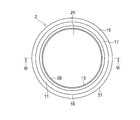
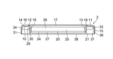
- FIG. 5 is an explanatory plan view of the upper case of the example shown in FIG. 6 is a cross-sectional explanatory view taken along the line VI-VI of the upper case shown in FIG. 5 of the example shown in FIG. 7 is a partially enlarged cross-sectional view of the upper case shown in FIG. 6 of the example shown in FIG.
- FIG. 1 is a cross-sectional explanatory view taken along the line II of FIG. 3 showing a preferred example of an embodiment of the present invention.
- FIG. 2 is an explanatory front view of the example shown in FIG.
- FIG. 3 is an explanatory plan
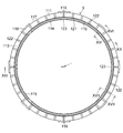
- FIG. 8 is an explanatory plan view of the lower case of the example shown in FIG. 9 is a cross-sectional explanatory view taken along line IX-IX of the lower case shown in FIG. 8 of the example shown in FIG. 10 is a cross-sectional explanatory view taken along the line XX of the lower case shown in FIG.
- FIG. 11 is a partially enlarged plan explanatory view of the lower case shown in FIG. 12 is a cross-sectional explanatory view taken along the line XII-XII of the lower case shown in FIG. 13 is a cross-sectional explanatory view taken along the line XIII-XIII of the plain bearing piece shown in FIG. 14 of the example shown in FIG. FIG.
- FIG. 14 is an explanatory plan view of the plain bearing piece shown in FIG.
- FIG. 15 is an explanatory bottom view of the sliding bearing piece shown in FIG. 16 is a cross-sectional explanatory view taken along the line XVI-XVI of the plain bearing piece shown in FIG. 17 is a cross-sectional explanatory view taken along the line XVII-XVII of the plain bearing piece shown in FIG.
- FIG. 18 is an explanatory perspective view of the lower case having the inner and outer seal members of the example shown in FIG. 1.
- FIG. 19 is an explanatory plan view of the lower case including the inner and outer seal members of the example shown in FIG.
- FIG. 20 is a cross-sectional explanatory view taken along the line XX-XX of the lower case provided with the inner and outer seal members shown in FIG. 21 is a cross-sectional explanatory view taken along the line XXI-XXI of the lower case having the inner and outer seal members shown in FIG. 22 is a cross-sectional explanatory view taken along the line XXII-XXII of the lower case provided with the inner and outer annular seal members shown in FIG. 23 is a cross-sectional explanatory view taken along the line XXIII-XXIII of FIG. 24 of another embodiment of the slide bearing piece of the example shown in FIG.
- FIG. 24 is an explanatory plan view of the plain bearing piece shown in FIG. FIG.
- FIG. 25 is an explanatory bottom view of the sliding bearing piece shown in FIG.
- FIG. 26 is a partially enlarged plan view of the slide bearing piece shown in FIG. 27 is a cross-sectional explanatory view taken along the line XXVII-XXVII of the plain bearing piece shown in FIG. 28 is a cross-sectional explanatory view taken along line XXVIII-XXVIII of the plain bearing piece shown in FIG.
- FIG. 29 is a cross-sectional explanatory view in which the slide bearing shown in FIG. 1 is incorporated in a strut suspension.
- a sliding bearing 1 of this example for use in a strut suspension in a four-wheeled vehicle includes an upper case 2 made of a synthetic resin that is fixed to a vehicle body via an attachment member, and an upper case 2.
- the lower case 3 made of a synthetic resin is superimposed on the upper case 2 so as to be rotatable in the circumferential direction R around the axis O and has a spring receiving seat for the suspension coil spring.
- a sliding bearing piece 5 made of synthetic resin disposed in an annular space 4 between the upper case 2 and the lower case 3, and a radial direction X between the upper case 2 and the lower case 3 communicating with the annular space 4 to the outside.
- An annular inner seal member 8 and an outer seal member 9 made of synthetic resin are provided to close the annular ring gap 6 on the circumferential side and the annular gap 7 on the outer circumferential side in the radial direction X, respectively.
- the upper case 2 includes an annular upper case base 11 having an annular lower surface 10 in the axial direction Y, and an inner circumference in the radial direction X of the annular lower surface 10 of the upper case base 11.
- an annular pedestal portion 17 formed so as to protrude from the central portion in the radial direction X.
- the inner cylindrical hanging portion 13 includes a thick cylindrical portion 19 connected to the inner peripheral end portion 12 of the annular lower surface 10 of the upper case base 11 at the upper end portion 18, an inner annular step surface 20, and an outer annular step portion.
- the upper cylindrical portion 19 is connected to the lower end portion 22 of the thick cylindrical portion 19 via the surface 21 and has a thin cylindrical portion 24 that is thinner than the thick cylindrical portion 19.
- the thick cylindrical portion 19 and the thin cylindrical portion 24 have cylindrical inner peripheral surfaces 26 and 27 that define a through hole 25 through which a shaft member of a strut suspension passes, and the thick cylindrical portion 19 is a cylinder.
- the thin cylindrical portion 24 has a smaller diameter than the outer peripheral surface 28, and has a frustoconical outer peripheral surface 30 that tapers from the outer annular stepped surface 21 to the annular end surface 29. is doing.
- the outer cylindrical hanging portion 15 having a cylindrical outer peripheral surface 31 is connected to the outer peripheral end portion 14 of the annular lower surface 10 of the upper case base portion 11 at the upper end portion 32 and is separated from the annular lower surface 10 of the upper case base portion 11.
- Each of which has a trapezoidal cross-section cylindrical portion 34 having an inner peripheral surface 33 whose diameter has been increased in accordance with the above and a cylindrical portion 36 connected to the lower end portion of the trapezoidal cross-section cylindrical portion 34 at the upper end portion 35.
- An annular end surface 38 of the cylindrical portion 36 having a cylindrical inner peripheral surface 37 that is connected to 33 is located below the annular end surface 29 of the thin cylindrical portion 24 of the inner cylindrical hanging portion 13 in the axial direction Y. .
- the lower case 3 is superimposed on the upper case 2 so as to be rotatable in the circumferential direction R around the axis O with respect to the upper case 2, and in the axial direction.
- An annular lower case base 40 having an annular upper surface 39 in Y, and projecting from the annular upper surface 39 of the lower case base 40 in the axial direction Y toward the annular lower surface 10 of the upper case base 11
- annular projecting portion 47 projecting inward from the inner surface 46, a cylindrical projecting portion 48 projecting downward in the axial direction Y at the end 45 of the cylindrical portion 44, and an annular upper surface 49 of the cylindrical projecting portion 41.
- Circle on outer periphery A plurality of curved shapes projecting upward in the axial direction Y leaving the flat surface portion 50 and spaced apart from each other in the circumferential direction R around the axis O along the outer peripheral edge portion.
- a plurality of protrusions 51 and a cylindrical inner surface 52 of the cylindrical protrusion 41 are integrally formed at equal intervals along the circumferential direction R and project inward in the radial direction X.
- An inner inward projection 53 having a rectangular shape in plan view and a cylindrical outer surface 54 of the cylindrical projection 41 are integrally formed at equal intervals along the circumferential direction R and are outward in the radial direction X.
- the cylindrical portion 44 is integrally provided with a plurality of outer outward projections 55 having a planar view shape protruding in a cylindrical shape, and the cylindrical portion 44 is connected to the annular lower surface 43 via an arcuate concave surface 56.
- the cylindrical protrusion 48 has a tapered outer surface 58 connected to the cylindrical outer surface 57. It has.
- the lower case base 40 is connected to the cylindrical inner surface 46 in addition to the annular upper surface 39, and is connected to the annular lower surface 43 via the cylindrical inner surface 46, the flush cylindrical inner surface 61, and the annular tapered outer surface 62.
- the protrusion 47 has a cylindrical inner surface 64.
- a cylindrical inner surface 52 of the cylindrical protrusion 41 is flush with the cylindrical inner surface 61 and is connected to the cylindrical inner surface 61, and is adjacent to the cylindrical inner surface 65 via an annular step surface 66.
- the cylindrical outer surface 54 of the cylindrical protrusion 41 is connected to the annular flat surface portion 50 of the annular upper surface 49 and is connected to the cylindrical outer surface 81, and the outer outer protrusion 55 is integrally formed.
- the annular step surface 82 and the annular step surface 82 are connected to the annular step surface 82 and extend downward in the axial direction Y beyond the annular step surface 66 and have a larger diameter than the cylindrical outer surface 81.
- a cylindrical outer surface 84 connected to the annular upper surface 39 through an arcuate concave surface 83.
- Each of the inner inward protrusions 53 integrally formed along the circumferential direction R on the cylindrical inner surface 71 of the cylindrical protrusion 41 is directed upward in the axial direction Y from the annular step surface 70.
- the upper end surface 85 of each inner inward projection 53 is located below the annular step surface 72 in the axial direction Y, and is formed integrally with the annular step surface 70.
- the arc-shaped concave inner surface 86 of the inner inward projection 53 is flush with the cylindrical inner surface 69.
- Each of the outer outer protrusions 55 integrally formed along the circumferential direction R on the cylindrical outer surface 81 of the cylindrical protrusion 41 is directed upward in the axial direction Y from the annular step surface 82. It extends and is formed integrally with the annular step surface 82, and the upper surface 87 of each outer outward projection 55 is located below the annular plane portion 50 in the axial direction Y.
- the arcuate convex outer surface 88 of the projecting portion 55 has a smaller diameter than the cylindrical outer surface 84 and is located inward in the radial direction Y.
- a plurality of hole portions 95 are formed in the annular upper surface 49 of the cylindrical protrusion 41 along the circumferential direction R downward in the axial direction Y.
- the hole 95 is tapered from the circular opening 96 to the bottom surface 97 defining the hole 95, and the hole 95 is defined by the frustoconical inner surface 98 and the circular bottom surface 97. Is provided in order to make the thickness of the cylindrical protrusion 41 of the lower case 3 uniform and the thickness of other portions to reduce defects such as sink marks during molding as much as possible.
- the outer cylindrical drooping portion communicating with the annular space 101, the annular space 104 between the outer peripheral surface 30 of the thin cylindrical portion 24 and the cylindrical inner surface 71 of the cylindrical protrusion 41 in the inner cylindrical drooping portion 13 communicating with the annular space 103.
- the annular space 105 between the inner peripheral surface 33 of the trapezoidal cross-section cylindrical portion 34 and the cylindrical outer surface 81 of the cylindrical protrusion 41, and the outer cylindrical hanging portion 15 communicating with the annular space 105.
- a synthetic resin sliding bearing piece 5 disposed in the annular spaces 101 and 102 in the annular space 4 having the annular space 106 between the inner peripheral surface 37 of the cylindrical portion 36 and the cylindrical outer surface 84 of the cylindrical protrusion 41. As shown in FIGS.
- annular upper surface 111 slidably contacting the annular lower surface 10 of the upper case base 11 and an annular lower surface contacting the annular upper surface 49 of the cylindrical protrusion 41.
- An annular thrust sliding bearing piece portion 113 having 112 respectively, and one end portion extending downward from one end portion of the thrust sliding bearing piece portion 113 in the axial direction X is formed integrally with the one end portion.
- a cylindrical inner peripheral surface 114 slidably contacting the outer peripheral surface 28 of the thick cylindrical portion 19 of the inner cylindrical hanging portion 13 and a cylindrical outer peripheral surface 115 contacting the cylindrical inner surface 73 of the cylindrical projection 41 are also provided.
- annular upper surface 111 in the axial direction X and a cylindrical inner peripheral surface 114 in the radial direction slidably contact the annular lower surface 10 of the upper case base 11 and the radial outer peripheral surface 28 of the inner cylindrical hanging portion 13.
- the annular lower surface 112 in the axial direction X and the cylindrical outer peripheral surface 115 in the radial direction Y are in contact with the annular upper surface 49 in the axial direction X of the cylindrical protrusion 41 and the cylindrical inner surface 73 in the radial direction Y.
- the thrust sliding bearing piece portion 113 is open at one end to the annular groove 121 provided on the inner peripheral side of the annular upper surface 111 and the annular groove 121.
- the radial sliding bearing piece 116 has a plurality of radial grooves 122 which are open at the outer peripheral surface 117 at the other end and are provided at equal intervals in the circumferential direction R on the upper surface 111.
- the groove 122 and the axial groove 123 serve as a reservoir for a lubricant such as grease.
- the inner seal member 8 covers the outer surfaces of the plurality of inner inner protrusions 53 of the cylindrical protrusion 41 and covers the cylindrical inner surfaces 69 and 71 and the annular step surface 70 of the cylindrical protrusion 41 and the inner inner surface.
- the annular inner seal base 131 joined to the outer surface of the protrusion 53 and the gap 133 between the outer peripheral surface 30 of the thin cylindrical portion 24 and the inner peripheral surface 132 of the inner seal base 131 in the inner cylindrical hanging portion 13 are closed.
- the flexibility is connected to the upper end of the inner peripheral surface 132 of the inner seal base 131 and elastically flexibly contacts the frustoconical outer peripheral surface 30 of the thin cylindrical portion 24 in the inner cylindrical hanging portion 13.
- the inner seal member 8 is configured such that the inner seal member 134 elastically flexes and contacts the frustoconical outer peripheral surface 30 of the thin-walled cylindrical portion 24.
- Inner cylindrical hanging part An annular gap 6 between the annular end surface 29 of the thin cylindrical portion 24 and the annular stepped surface 66 of the cylindrical projection 41 which is the axial end portion of the annular space 4 and communicating the annular space 104 of the annular space 4 to the outside. Close.
- the inner seal portion 134 has a thickness smaller than that of the inner seal base portion 131 and extends obliquely downward from the upper end portion of the inner peripheral surface 132 of the inner seal base portion 131.
- the outer seal member 9 covers the outer surfaces of the plurality of outer outer protrusions 55 of the cylindrical protrusion 41 so as to cover the cylindrical outer surface 81 and the annular step surface 82 of the cylindrical protrusion 41 and the outer outer protrusion. 55 to close the gap 143 between the annular outer seal base 141 joined to the outer surface of 55 and the inner peripheral surface 33 of the trapezoidal cross section cylindrical portion 34 and the outer peripheral surface 142 of the outer seal base 141 in the outer cylindrical hanging portion 15.
- the outer seal portion connected to the upper end portion of the outer peripheral surface 142 of the outer seal base portion 141 and elastically flexibly contacts the frustoconical inner peripheral surface 33 of the trapezoidal cross-section cylindrical portion 34 in the outer cylindrical hanging portion 15.
- the outer seal portion 144, and the outer annular seal member 9 is configured such that the outer seal portion 144 is elastically flexibly brought into contact with the inner peripheral surface 33 of the trapezoidal cross-section cylindrical portion 34 of the outer cylindrical drooping portion 15. of A between the annular upper surface 39 of the annular end face 38 and the lower case base 40 of the cylindrical portion 36 is a direction end portion to close the annular gap 7 for communicating the annular space 106 of the annular space 4 to the outside.
- the outer seal portion 144 has a thickness smaller than that of the outer seal base portion 141 and extends obliquely downward from the upper end portion of the outer peripheral surface 142 of the outer seal base portion 141.
- the outer seal base 141 may cover the annular flat surface portion 50.
- the inner seal member 8 composed of the annular inner seal base 131 and the inner seal portion 134 is insert-molded on the cylindrical protrusion 41 on the cylindrical inner surface 71 and is formed on the cylindrical inner surface 71 of the cylindrical protrusion 41.
- the outer seal member 9 including the base portion 141 and the outer seal portion 144 is formed by being insert-molded on the cylindrical projection 41 on the cylindrical outer surface 81 and integrally joined to the cylindrical outer surface 81 of the cylindrical projection 41. .
- the slide bearing 1 described above is configured so that the relative rotation in the circumferential direction R of the lower case 3 with respect to the upper case 2 is caused by the upper surface 111 of the thrust slide bearing piece 113 and the thick cylindrical portion 19 with respect to the annular lower surface 10 of the upper case base 11.
- the relative sliding in the circumferential direction R of the inner peripheral surface 114 of the radial plain bearing piece 116 with respect to the outer peripheral surface 28 is allowed.
- the inner seal member 8 is inserted into the cylindrical inner surface 71 of the cylindrical protrusion 41 of the lower case 3, and the outer seal member 9 is inserted into the cylindrical outer surface 81 of the cylindrical protrusion 41 of the lower case 3. Since it is integrally formed by molding, the number of parts can be reduced, the assemblability can be reduced, the manufacturing cost can be reduced, and the possibility of dropping off can be eliminated and the durability can be improved. .
- the inner side that closes the annular gap 6 between the annular end surface 29 of the inner cylindrical hanging portion 13 of the upper case 2 and the annular step surface 66 of the cylindrical protrusion 41 of the lower case 3 is closed. It has a seal member 8, and has an outer seal member 9 that closes the annular gap 7 between the annular end surface 38 of the outer cylindrical hanging portion 15 of the upper case 2 and the annular upper surface 39 of the lower case base 40 of the lower case 3. Therefore, the sealing performance can be improved, and entry of foreign matters such as dust from the annular gaps 6 and 7 into the sliding surfaces of the annular space 4 can be prevented.
- annular upper surface 111 slidably contacting the annular lower surface 10 of the upper case base 11 and an annular lower surface contacting the annular upper surface 49 of the cylindrical protrusion 41.
- An annular thrust sliding bearing piece 113 having 112 respectively, and a thickness of the inner cylindrical hanging part 13 of the upper case 2 formed integrally with one end of the thrust sliding bearing piece 113 at one end.
- a cylindrical inner peripheral surface 114 that is slidably in contact with the outer peripheral surface 28 of the meat cylindrical portion 19 and a cylindrical outer peripheral surface 115 that is in contact with the cylindrical inner surface 73 of the cylindrical protrusion 41, and the lower side in the axial direction Y.
- a cylindrical radial sliding bearing piece 116 extending in the direction of the outer circumferential surface 117 of the thrust sliding bearing piece 113 and projecting outward in the radial direction X, and the sliding bearing piece 5 extends in the circumferential direction with respect to the lower case 3. Does not rotate to R In the circumferential direction R, the protrusions 51 adjacent to each other are arranged at the cuts 118 between the plurality of curved protrusions 51 erected along the outer peripheral edge of the annular upper surface 49 of the cylindrical protrusion 41.
- the thrust sliding bearing piece 113 extends along the circumferential direction R on the annular upper surface 111, and A plurality of inner recesses 151 and outer recesses 152 that are formed in at least two rows of the inner row and the outer row in the radial direction and are arranged with a phase difference in the circumferential direction R may be provided.
- Each of the inner recesses 151 formed in the inner row has an inner arcuate surface 153 extending in an arc shape with the axis O as the center, and an axis O outside the radial direction Y with respect to the inner arcuate surface 153.
- An outer arcuate surface 154 extending in an arc shape as a center, and a pair of semicircular surfaces 155 connected to both ends of the inner arcuate surface 153 and the outer arcuate surface 154 and facing each other in the circumferential direction R;
- the inner arcuate surface 153, the outer arcuate surface 154, and the bottom surface 156 connected to each of the pair of semicircular surfaces 155.
- Each of the outer recesses 152 formed in the outer row has an inner arc-shaped surface 161 extending in an arc shape with the axis O as the center, and the axis O outside the radial direction Y with respect to the inner arc-shaped surface 161.
- An outer arc-shaped surface 162 extending in an arc shape as a center, a pair of semicircular surfaces 163 connected to each of the inner arc-shaped surface 161 and the outer arc-shaped surface 162 and facing each other in the circumferential direction R;
- the outer recess 152 is defined by a bottom surface 164 connected to each of the inner arc-shaped surface 161, the outer arc-shaped surface 162, and the pair of semicircular surfaces 163, and the outer recess 152 is a cut 165 in the circumferential direction R between the inner recesses 151.
- the small circular portions 171 arranged at intervals of 60 ° along the circumferential direction R indicate the positions of the protruding pins from the mold when the sliding bearing piece 5 is formed, and are not arranged in the inner concave portion 151.
- the plurality of inner recesses 151 and the outer recesses 152 occupy a plurality of surfaces in which the opening surfaces 175 and 176 of the inner recesses 151 and outer recesses 152 and the annular upper surface 111 of the thrust slide bearing piece 113 are combined.
- the ratio of the total area of the opening surfaces 175 and 176 of the individual inner recess 151 and outer recess 152 is 20 to 50%, preferably 30 to 40%.
- the radial plain bearing piece 116 shown in FIGS. 23 to 28 is also opened at both ends in the axial direction Y and is provided with a plurality of shafts provided at equal intervals in the circumferential direction R on the cylindrical inner peripheral surface 114.
- a directional groove 123 may be provided.
- the axial groove 123 formed on the inner peripheral surface 114 of the bearing piece 116 serves as a reservoir for a lubricant such as grease.
- the annular upper surface 111 and the upper portion of the thrust slide bearing piece portion 113 are formed by the inner concave portion 151 and the outer concave portion 152 formed in the annular upper surface 111.
- the annular upper surface 111 which is a thrust sliding bearing surface and becomes a sliding surface, and the counterpart material, that is, the upper case 2
- the pedestal 17 of the annular upper surface 16 of the upper case 2 is brought into contact with the vehicle body side seating surface 182 of the strut suspension, the vehicle body side mounting member 181, and the upper end portion of the suspension coil spring 183.
- the annular lower surface 43 of the lower case 3 is brought into contact with the spring seat surface 184 so that the sliding bearing 1 made of synthetic resin in this example is connected to the vehicle body side seat surface 182 of the vehicle body side mounting member 181 and the suspension coil spring 183.
- the synthetic resin sliding bearing 1 of this example may be applied to a strut suspension in a four-wheeled vehicle.
Landscapes
- Engineering & Computer Science (AREA)
- General Engineering & Computer Science (AREA)
- Mechanical Engineering (AREA)
- Chemical & Material Sciences (AREA)
- Oil, Petroleum & Natural Gas (AREA)
- Sliding-Contact Bearings (AREA)
- Vehicle Body Suspensions (AREA)
- Sealing Of Bearings (AREA)
- Support Of The Bearing (AREA)
Abstract
Description
2 上部ケース
3 下部ケース
4 環状空間
5 滑り軸受片
6、7 環状隙間
8 内側環状シール部材
9 外側環状シール部材
Claims (9)
- 軸方向において円環状下面を有した円環状の上部ケース基部、この上部ケース基部の円環状下面の径方向の内周端部から垂下した内側円筒垂下部及び上部ケース基部の円環状下面の径方向の外周端部から垂下した外側円筒垂下部を夫々一体的に有した合成樹脂製の上部ケースと、この上部ケースに対して軸心の回りで回転自在となるように当該上部ケースに重ね合わされていると共に軸方向において円環状上面を有した円環状の下部ケース基部及びこの下部ケース基部の円環状上面から上部ケース基部の円環状下面に向かって突出した円筒状突部、この円筒状突部の円筒内面に円周方向に沿って一体的に形成されていると共に径方向内方に突出した複数個の内側内方突部、該円筒状突部の円筒外面に円周方向に沿って一体的に形成されていると共に径方向外方に突出した複数個の外側外方突部を夫々一体的に有した合成樹脂製の下部ケースと、軸方向における円環状の上面及び径方向の円筒状の内周面で上部ケース基部の円環状下面及び内側円筒垂下部の径方向の外周面に摺動自在に接触する一方、軸方向における円環状の下面及び径方向の円筒状の外周面で円筒状突部の軸方向における環状上面及び径方向の円筒内面に接触するように、上部ケース基部の円環状下面及び円筒状突部の環状上面間の環状空間並びに内側円筒垂下部の外周面及び円筒状突部の円筒内面間の環状空間に配された合成樹脂製の滑り軸受片と、円筒状突部の複数個の内側内方突部を覆って当該円筒状突部の円筒内面に接合された円環状の内側シール基部並びに上部ケースの内側円筒垂下部の外周面及び内側シール基部の内周面間の隙間を閉鎖するように、この内側シール基部の内周面に連接されていると共に上部ケースの内側円筒垂下部の外周面に弾性的に撓み接触する可撓性の内側シール部を有した内側シール部材と、円筒状突部の複数個の外側外方突部を覆って当該円筒状突部の円筒外面に接合された円環状の外側シール基部並びに上部ケースの外側円筒垂下部の内周面及び外側シール基部の外周面間の隙間を閉鎖するように、この外側シール基部の外周面に連接されていると共に上部ケースの外側円筒垂下部の内周面に弾性的に撓み接触する可撓性の外側シール部を有した外側シール部材とを有する合成樹脂製の滑り軸受。
- 内側シール部は、内側シール基部の厚みよりも小さい厚みを有していると共に内側シール基部の内周面から斜め下方に伸びている請求項1に記載の合成樹脂製の滑り軸受。
- 外側シール部は、外側シール基部の厚みよりも小さい厚みを有していると共に外側シール基部の外周面から斜め下方に伸びている請求項1又は2に記載の合成樹脂製の滑り軸受。
- 下部ケースは、当該下部ケースの円筒状突部の環状上面の外周縁部に当該外周縁部に沿って立設された複数個の湾曲状の突起部を更に具備しており、滑り軸受片は、上部ケース基部の円環状下面に摺動自在に接触する円環状の上面及び円筒状突部の環状上面に接触する円環状の下面を夫々有している円環状のスラスト滑り軸受片部と、一端部でスラスト滑り軸受片部の一端部から軸方向の下方に伸びて当該一端部に一体的に形成されていると共に内側円筒垂下部の外周面に摺動自在に接触する円筒状の内周面及び円筒状突部の円筒内面に接触する円筒状の外周面を夫々有した円筒状のラジアル滑り軸受片部と、下部ケースに対して滑り軸受片が円周方向に回転しないように、スラスト滑り軸受片部の外周面から径方向外方に突出していると共に下部ケースの複数個の湾曲状の突起部間に配された複数個の径方向突板片部とを具備している請求項1から3のいずれか一項に記載の合成樹脂製の滑り軸受。
- スラスト滑り軸受片部は、その円環状の上面の内周側に形成された円環状溝と、円環状溝に一端で開口している一方、他端でその外周面で開口していると共にその上面に円周方向に等間隔に離間して形成された複数個の径方向溝とを有しており、ラジアル滑り軸受片部は、両端で開口して円筒状の内周面に円周方向に等間隔に離間して設けられた複数個の軸方向溝を有している請求項4に記載の合成樹脂製の滑り軸受。
- スラスト滑り軸受片部は、その円環状の上面に円周方向に沿い、かつ径方向に少なくとも内側列と外側列との二列にわたって形成されていると共に互いに円周方向に位相差をもって配列された複数個の内側凹部及び外側凹部を有しており、ラジアル滑り軸受片部は、両端で開口して円筒状の内周面に円周方向に等間隔に離間して形成された複数個の軸方向溝を有している請求項4に記載の合成樹脂製の滑り軸受。
- 複数個の内側凹部の夫々は、軸心を中心として円弧状に伸びた内側円弧状面と、該内側円弧状面に対して径方向外方で軸心を中心として円弧状に伸びた外側円弧状面と、該内側円弧状面及び該外側円弧状面の夫々に連接されていると共に互いに円周方向において対面する一対の半円状面と、該内側円弧状面、該外側円弧状面及び該一対の半円状面の夫々に連接された底面とによって規定されている請求項6に記載の合成樹脂製の滑り軸受。
- 複数個の外側凹部の夫々は、軸心を中心として円弧状に伸びた内側円弧状面と、該内側円弧状面に対して径方向外方で軸心を中心として円弧状に伸びた外側円弧状面と、該内側円弧状面及び外側円弧状面の夫々に連接されていると共に互いに円周方向において対面する一対の半円状面と、該内側円弧状面、該外側円弧状面及び当該一対の半円状面の夫々に連接された底面とによって規定されている請求項6又は7に記載の合成樹脂製の滑り軸受。
- 複数個の内側凹部及び外側凹部の開口面とスラスト滑り軸受片部の円環状の上面とを合わせた面に占める複数個の内側凹部及び外側凹部の開口面の総面積の割合は、20~50%である請求項6から8のいずれか一項に記載の合成樹脂製の滑り軸受。
Priority Applications (6)
| Application Number | Priority Date | Filing Date | Title |
|---|---|---|---|
| US14/349,446 US9239081B2 (en) | 2011-10-07 | 2012-10-02 | Synthetic resin-made sliding bearing |
| KR1020147009073A KR101527347B1 (ko) | 2011-10-07 | 2012-10-02 | 합성 수지제의 미끄럼 베어링 |
| RU2014113186/11A RU2562820C1 (ru) | 2011-10-07 | 2012-10-02 | Подшипник скольжения из синтетической смолы |
| BR112014006767-8A BR112014006767B1 (pt) | 2011-10-07 | 2012-10-02 | Mancal de deslizamento feito de resina sintética |
| CN201280048846.1A CN103857933B (zh) | 2011-10-07 | 2012-10-02 | 合成树脂制成的滑动轴承 |
| EP12839098.6A EP2765320B1 (en) | 2011-10-07 | 2012-10-02 | Synthetic-resin sliding bearing |
Applications Claiming Priority (2)
| Application Number | Priority Date | Filing Date | Title |
|---|---|---|---|
| JP2011223476A JP5909976B2 (ja) | 2011-10-07 | 2011-10-07 | 合成樹脂製の滑り軸受 |
| JP2011-223476 | 2011-10-07 |
Publications (1)
| Publication Number | Publication Date |
|---|---|
| WO2013051240A1 true WO2013051240A1 (ja) | 2013-04-11 |
Family
ID=48043423
Family Applications (1)
| Application Number | Title | Priority Date | Filing Date |
|---|---|---|---|
| PCT/JP2012/006313 Ceased WO2013051240A1 (ja) | 2011-10-07 | 2012-10-02 | 合成樹脂製の滑り軸受 |
Country Status (8)
| Country | Link |
|---|---|
| US (1) | US9239081B2 (ja) |
| EP (1) | EP2765320B1 (ja) |
| JP (1) | JP5909976B2 (ja) |
| KR (1) | KR101527347B1 (ja) |
| CN (2) | CN107165943B (ja) |
| BR (1) | BR112014006767B1 (ja) |
| RU (1) | RU2562820C1 (ja) |
| WO (1) | WO2013051240A1 (ja) |
Cited By (1)
| Publication number | Priority date | Publication date | Assignee | Title |
|---|---|---|---|---|
| US10422374B2 (en) | 2015-11-20 | 2019-09-24 | Oiles Corporation | Synthetic resin-made sliding bearing |
Families Citing this family (7)
| Publication number | Priority date | Publication date | Assignee | Title |
|---|---|---|---|---|
| JP5910000B2 (ja) * | 2011-11-02 | 2016-04-27 | オイレス工業株式会社 | 合成樹脂製の滑り軸受 |
| JP2013148132A (ja) * | 2012-01-17 | 2013-08-01 | Oiles Corp | スラスト滑り軸受 |
| JP6303239B2 (ja) * | 2014-08-12 | 2018-04-04 | オイレス工業株式会社 | スラスト滑り軸受 |
| JP6581448B2 (ja) * | 2015-09-09 | 2019-09-25 | オイレス工業株式会社 | 滑り軸受 |
| JP2020091031A (ja) * | 2018-12-07 | 2020-06-11 | オイレス工業株式会社 | 滑り軸受およびステアリングシャフト支持構造 |
| CN114738383A (zh) * | 2021-01-07 | 2022-07-12 | 易格斯(上海)拖链系统有限公司 | 塑料滑动轴承 |
| JP7719443B2 (ja) * | 2021-10-22 | 2025-08-06 | 中西金属工業株式会社 | ストラットベアリング装置、及び車両のストラット式サスペンション |
Citations (6)
| Publication number | Priority date | Publication date | Assignee | Title |
|---|---|---|---|---|
| JP2001027229A (ja) | 1999-07-15 | 2001-01-30 | Oiles Ind Co Ltd | 合成樹脂製の滑り軸受 |
| JP2001027227A (ja) | 1999-07-15 | 2001-01-30 | Oiles Ind Co Ltd | 合成樹脂製の滑り軸受 |
| JP2001027228A (ja) | 1999-07-15 | 2001-01-30 | Oiles Ind Co Ltd | 合成樹脂製の滑り軸受 |
| WO2007132557A1 (ja) * | 2006-05-15 | 2007-11-22 | Oiles Corporation | 滑り軸受 |
| WO2012017591A1 (ja) * | 2010-08-06 | 2012-02-09 | オイレス工業株式会社 | スラスト滑り軸受 |
| WO2012114679A1 (ja) * | 2011-02-23 | 2012-08-30 | オイレス工業株式会社 | 合成樹脂製のスラスト滑り軸受 |
Family Cites Families (14)
| Publication number | Priority date | Publication date | Assignee | Title |
|---|---|---|---|---|
| JP3988397B2 (ja) * | 2001-02-27 | 2007-10-10 | オイレス工業株式会社 | 合成樹脂製の滑り軸受 |
| CN100436850C (zh) * | 2002-10-03 | 2008-11-26 | 奥依列斯工业株式会社 | 滑动轴承 |
| JP4378983B2 (ja) * | 2003-03-25 | 2009-12-09 | オイレス工業株式会社 | ストラット滑り軸受 |
| FR2865008B1 (fr) * | 2004-01-13 | 2006-03-31 | Skf Ab | Dispositif de roulement de butee de suspension. |
| JP4506262B2 (ja) * | 2004-04-28 | 2010-07-21 | 日本精工株式会社 | 転がり軸受ユニットの密封手段転がり軸受ユニット |
| JP5561660B2 (ja) * | 2006-05-12 | 2014-07-30 | オイレス工業株式会社 | 滑り軸受 |
| JP5157210B2 (ja) * | 2007-03-20 | 2013-03-06 | オイレス工業株式会社 | スラスト滑り軸受並びにこのスラスト滑り軸受とピストンロッド及びコイルばねとの組合せ機構 |
| JP5347966B2 (ja) * | 2007-09-27 | 2013-11-20 | オイレス工業株式会社 | 合成樹脂製スラスト滑り軸受 |
| JP5233370B2 (ja) * | 2008-04-02 | 2013-07-10 | オイレス工業株式会社 | スラスト滑り軸受 |
| JP5245508B2 (ja) * | 2008-04-18 | 2013-07-24 | オイレス工業株式会社 | スラスト滑り軸受 |
| JP5332379B2 (ja) * | 2008-07-28 | 2013-11-06 | オイレス工業株式会社 | 合成樹脂製スラスト滑り軸受 |
| FR2934656B1 (fr) * | 2008-08-01 | 2013-05-17 | Skf Ab | Dispositif de butee de suspension et jambe de force. |
| DE102008057590A1 (de) * | 2008-08-13 | 2010-02-18 | Schaeffler Kg | Federbeingleitlager |
| JP5906590B2 (ja) * | 2011-06-09 | 2016-04-20 | オイレス工業株式会社 | 合成樹脂製の滑り軸受 |
-
2011
- 2011-10-07 JP JP2011223476A patent/JP5909976B2/ja active Active
-
2012
- 2012-10-02 EP EP12839098.6A patent/EP2765320B1/en active Active
- 2012-10-02 RU RU2014113186/11A patent/RU2562820C1/ru not_active IP Right Cessation
- 2012-10-02 CN CN201710357534.3A patent/CN107165943B/zh active Active
- 2012-10-02 BR BR112014006767-8A patent/BR112014006767B1/pt active IP Right Grant
- 2012-10-02 CN CN201280048846.1A patent/CN103857933B/zh active Active
- 2012-10-02 KR KR1020147009073A patent/KR101527347B1/ko active Active
- 2012-10-02 US US14/349,446 patent/US9239081B2/en active Active
- 2012-10-02 WO PCT/JP2012/006313 patent/WO2013051240A1/ja not_active Ceased
Patent Citations (6)
| Publication number | Priority date | Publication date | Assignee | Title |
|---|---|---|---|---|
| JP2001027229A (ja) | 1999-07-15 | 2001-01-30 | Oiles Ind Co Ltd | 合成樹脂製の滑り軸受 |
| JP2001027227A (ja) | 1999-07-15 | 2001-01-30 | Oiles Ind Co Ltd | 合成樹脂製の滑り軸受 |
| JP2001027228A (ja) | 1999-07-15 | 2001-01-30 | Oiles Ind Co Ltd | 合成樹脂製の滑り軸受 |
| WO2007132557A1 (ja) * | 2006-05-15 | 2007-11-22 | Oiles Corporation | 滑り軸受 |
| WO2012017591A1 (ja) * | 2010-08-06 | 2012-02-09 | オイレス工業株式会社 | スラスト滑り軸受 |
| WO2012114679A1 (ja) * | 2011-02-23 | 2012-08-30 | オイレス工業株式会社 | 合成樹脂製のスラスト滑り軸受 |
Non-Patent Citations (1)
| Title |
|---|
| See also references of EP2765320A4 * |
Cited By (1)
| Publication number | Priority date | Publication date | Assignee | Title |
|---|---|---|---|---|
| US10422374B2 (en) | 2015-11-20 | 2019-09-24 | Oiles Corporation | Synthetic resin-made sliding bearing |
Also Published As
| Publication number | Publication date |
|---|---|
| US20140248009A1 (en) | 2014-09-04 |
| JP5909976B2 (ja) | 2016-04-27 |
| CN107165943A (zh) | 2017-09-15 |
| KR20140060346A (ko) | 2014-05-19 |
| EP2765320A4 (en) | 2015-03-25 |
| EP2765320A1 (en) | 2014-08-13 |
| BR112014006767B1 (pt) | 2020-09-29 |
| CN107165943B (zh) | 2019-05-07 |
| JP2013083303A (ja) | 2013-05-09 |
| CN103857933A (zh) | 2014-06-11 |
| BR112014006767A2 (pt) | 2017-04-04 |
| CN103857933B (zh) | 2017-09-05 |
| EP2765320B1 (en) | 2019-11-20 |
| KR101527347B1 (ko) | 2015-06-09 |
| RU2562820C1 (ru) | 2015-09-10 |
| US9239081B2 (en) | 2016-01-19 |
Similar Documents
| Publication | Publication Date | Title |
|---|---|---|
| JP5516210B2 (ja) | スラスト滑り軸受 | |
| JP5906590B2 (ja) | 合成樹脂製の滑り軸受 | |
| JP5909976B2 (ja) | 合成樹脂製の滑り軸受 | |
| JP6057814B2 (ja) | 合成樹脂製の滑り軸受 | |
| WO2013108596A1 (ja) | スラスト滑り軸受 | |
| WO2013065273A1 (ja) | 合成樹脂製の滑り軸受 | |
| JP6017340B2 (ja) | 合成樹脂製の滑り軸受 | |
| JP6322889B2 (ja) | 合成樹脂製の滑り軸受 | |
| JP6631648B2 (ja) | 合成樹脂製の滑り軸受 | |
| JP6319345B2 (ja) | 合成樹脂製の滑り軸受 | |
| JPWO2017094686A1 (ja) | 合成樹脂製滑り軸受 | |
| JP4788803B2 (ja) | スラスト滑り軸受 | |
| JP2016008711A (ja) | スラスト滑り軸受 |
Legal Events
| Date | Code | Title | Description |
|---|---|---|---|
| 121 | Ep: the epo has been informed by wipo that ep was designated in this application |
Ref document number: 12839098 Country of ref document: EP Kind code of ref document: A1 |
|
| WWE | Wipo information: entry into national phase |
Ref document number: 2012839098 Country of ref document: EP |
|
| WWE | Wipo information: entry into national phase |
Ref document number: 14349446 Country of ref document: US |
|
| ENP | Entry into the national phase |
Ref document number: 20147009073 Country of ref document: KR Kind code of ref document: A |
|
| NENP | Non-entry into the national phase |
Ref country code: DE |
|
| ENP | Entry into the national phase |
Ref document number: 2014113186 Country of ref document: RU Kind code of ref document: A |
|
| REG | Reference to national code |
Ref country code: BR Ref legal event code: B01A Ref document number: 112014006767 Country of ref document: BR |
|
| ENP | Entry into the national phase |
Ref document number: 112014006767 Country of ref document: BR Kind code of ref document: A2 Effective date: 20140320 |