WO2013051441A1 - ステアリングコラム装置 - Google Patents
ステアリングコラム装置 Download PDFInfo
- Publication number
- WO2013051441A1 WO2013051441A1 PCT/JP2012/074664 JP2012074664W WO2013051441A1 WO 2013051441 A1 WO2013051441 A1 WO 2013051441A1 JP 2012074664 W JP2012074664 W JP 2012074664W WO 2013051441 A1 WO2013051441 A1 WO 2013051441A1
- Authority
- WO
- WIPO (PCT)
- Prior art keywords
- hole
- column
- rear direction
- spacer
- sandwiched
- Prior art date
- Legal status (The legal status is an assumption and is not a legal conclusion. Google has not performed a legal analysis and makes no representation as to the accuracy of the status listed.)
- Ceased
Links
Images







Classifications
-
- B—PERFORMING OPERATIONS; TRANSPORTING
- B62—LAND VEHICLES FOR TRAVELLING OTHERWISE THAN ON RAILS
- B62D—MOTOR VEHICLES; TRAILERS
- B62D1/00—Steering controls, i.e. means for initiating a change of direction of the vehicle
- B62D1/02—Steering controls, i.e. means for initiating a change of direction of the vehicle vehicle-mounted
- B62D1/16—Steering columns
- B62D1/18—Steering columns yieldable or adjustable, e.g. tiltable
-
- B—PERFORMING OPERATIONS; TRANSPORTING
- B62—LAND VEHICLES FOR TRAVELLING OTHERWISE THAN ON RAILS
- B62D—MOTOR VEHICLES; TRAILERS
- B62D1/00—Steering controls, i.e. means for initiating a change of direction of the vehicle
- B62D1/02—Steering controls, i.e. means for initiating a change of direction of the vehicle vehicle-mounted
- B62D1/16—Steering columns
-
- B—PERFORMING OPERATIONS; TRANSPORTING
- B62—LAND VEHICLES FOR TRAVELLING OTHERWISE THAN ON RAILS
- B62D—MOTOR VEHICLES; TRAILERS
- B62D1/00—Steering controls, i.e. means for initiating a change of direction of the vehicle
- B62D1/02—Steering controls, i.e. means for initiating a change of direction of the vehicle vehicle-mounted
- B62D1/16—Steering columns
- B62D1/18—Steering columns yieldable or adjustable, e.g. tiltable
- B62D1/184—Mechanisms for locking columns at selected positions
-
- B—PERFORMING OPERATIONS; TRANSPORTING
- B62—LAND VEHICLES FOR TRAVELLING OTHERWISE THAN ON RAILS
- B62D—MOTOR VEHICLES; TRAILERS
- B62D1/00—Steering controls, i.e. means for initiating a change of direction of the vehicle
- B62D1/02—Steering controls, i.e. means for initiating a change of direction of the vehicle vehicle-mounted
- B62D1/16—Steering columns
- B62D1/18—Steering columns yieldable or adjustable, e.g. tiltable
- B62D1/185—Steering columns yieldable or adjustable, e.g. tiltable adjustable by axial displacement, e.g. telescopically
Definitions
- This invention relates to a steering column device for supporting a steering shaft that rotates based on an operation of a steering wheel provided in a driver's seat on the inside thereof.
- the automobile steering device transmits the rotation of the steering wheel 1 to the input shaft 3 of the steering gear unit 2, and pushes and pulls the pair of left and right tie rods 4 as the input shaft 3 rotates.
- the front wheel is configured to give a rudder angle.
- the steering wheel 1 is supported and fixed to the rear end portion of the steering shaft 5, and the steering shaft 5 is rotatably supported by the steering column 6 with the cylindrical steering column 6 inserted in the axial direction. Yes.
- the front end portion of the steering shaft 5 is connected to the rear end portion of the intermediate shaft 8 via the universal joint 7, and the front end portion of the intermediate shaft 8 is connected to the input shaft 3 via another universal joint 9. is doing.
- the vertical position and the front / rear position of the steering wheel 1 can be adjusted according to the physique and driving posture of the driver.
- the front end portion of the steering column 6 is supported by the horizontal shaft 10 so as to be able to swing and displace with respect to the vehicle body.
- the sandwiched bracket 12 fixed to the portion near the rear end of the intermediate portion of the steering column 6 is sandwiched between a pair of sandwiching plate portions 14 constituting the sandwiching bracket 13 assembled to the vehicle body 11.
- the rod 15 inserted into the sandwiched bracket 12 is inserted into the vertically elongated hole 16 formed in the portion of the sandwiching plate portion 14 aligned with each other.
- the vertical position of the steering wheel 1 can be adjusted within a range in which the rod 15 can be displaced in the vertical slot 16.
- the steering shaft 5 and the steering column 6 are configured to be extendable and contractible.
- the steering shaft 5 enables torque transmission by non-circularly engaging the rear end portion of the front inner shaft 17 and the front end portion of the rear outer shaft 18 by spline engagement or the like.
- the steering column 6 has the structure which combined the displacement of an axial direction possible.
- the steering column 6 has a structure in which the rear end portion of the front inner column 19 and the front end portion of the rear outer column 20 are combined in a state in which they can be displaced in the axial direction.
- a longitudinally long hole 21 is formed in the sandwiched bracket 12 for inserting the rod 15. The front / rear position of the steering wheel 1 can be adjusted within a range in which the rod 15 can be displaced within the longitudinal slot 21.
- the distance between the head 22 provided at the proximal end of the rod 15 and the pressing piece 23 (see FIG. 5) fitted around the distal end is determined by an adjustment handle (not shown) attached to the rod 15 and the adjustment handle. Can be expanded and contracted by using a cam device (not shown) that operates according to the above.
- the vertical position and the front-rear position of the steering wheel 1 can be adjusted in a state where the distance between the head 22 and the pressing piece 23 is widened. On the other hand, the vertical position and the front-rear position of the steering wheel 1 are held at the adjusted positions in a state where the distance between the head 22 and the pressing piece 23 is reduced.
- the outer column including the sandwiched bracket that constitutes such an automobile steering device it is effective to integrally configure the sandwiched bracket and the outer column.
- a rocking shaft is inserted through a horizontal shaft 10a for supporting the front end portion of the steering column 6a so as to be capable of rocking displacement with respect to the vehicle body 11a.
- a structure in which the dynamic support bracket portion 26 is provided integrally with the steering column 6a is described.
- the swing support bracket portion 26 is configured such that the metal tube constituting the steering column 6a is installed in the mold, and a high-pressure liquid is fed into the mold to match the shape of the inner surface of the mold. It is formed by a hydroforming method that partially bulges.
- the sandwiched bracket portion formed by the hydroforming method is thin, and the strength and rigidity are lowered accordingly. For this reason, in order to hold the steering wheel in the adjusted position, if the pair of left and right sandwiching plate portions provided on the sandwiching bracket is strongly clamped, the sandwiched bracket portion is deformed in the direction in which the width dimension is reduced. Cheap. And when the to-be-clamped bracket part deform
- An object of the present invention is a structure in which a clamped bracket part is integrally formed at the end of an outer column by a hydroforming method or the like, and the strength and rigidity of the clamped bracket part can be substantially secured, and if necessary
- Another object of the present invention is to provide a steering column device that can satisfactorily engage the clamped bracket portion and the rod.
- the steering column device of the present invention includes a cylindrical inner column, a cylindrical outer column, a clamped bracket portion, and a spacer.
- a steering column is formed by fitting the end of the outer column with the end of the inner column.
- the sandwiched bracket portion is formed by causing a metal plate constituting the outer column to bulge radially outward at an end portion of the outer column fitted with an end portion of the inner column. It is integrally formed. Further, the sandwiched bracket portion includes a pair of left and right sandwiched plate portions that are parallel to each other, and an interval between the sandwiched plate portions is set at a portion where these sandwiched plate portions are aligned with each other. A pair of through-holes for inserting rods for expansion and contraction are provided.
- the spacer is assembled between the held plate portions inside the held bracket portion.
- the spacer is formed of a material softer than a metal material such as an iron-based alloy or an aluminum-based alloy that constitutes the outer column, such as a polymer material such as synthetic resin or hard vinyl.
- the penetration hole for inserting the said rod is provided in the part which aligns with the said through-hole among the said spacers.
- the end portion of the outer column is fitted with the end portion of the inner column so as to be capable of relative displacement in the axial direction to form a telescopic steering column.
- the sandwiched bracket portion is provided so as to protrude upward from an end portion of the outer column.
- Each of the through-holes is a pair of slits provided in a state of projecting downward in the front-rear direction long hole portions that are long in the axial direction of the outer column and the front-rear ends of the front-rear direction long hole portions. It is comprised by a notch part.
- the insertion hole is provided in a portion of the through hole that is aligned with the longitudinal slot part in the front-rear direction and is long in the front-rear direction, and the width dimension in the vertical direction is the upper and lower parts of the longitudinal slot part. It is constituted by a long hole smaller than the width dimension in the direction.
- a locking projection that fits with the notch is provided on the lower part of both ends in the front-rear direction of the long hole in a part of the left and right outer surfaces of the spacer. Then, the upper surface of the spacer is brought into contact with the inner surface of the sandwiched bracket portion. Further, the upper and lower edges of the insertion hole in the state in which the locking projections are respectively engaged with the notch portions, the insertion hole is more than the upper and lower edges of the longitudinally long hole portion. And it exists inside on the width direction of the said front-back direction long hole part. Thereby, the outer peripheral surface of the rod inserted through the insertion hole and the front / rear direction long hole portion is prevented from contacting the inner peripheral edge of the front / rear direction long hole portion of the sandwiched bracket portion.
- the sandwiched bracket portion is provided so as to protrude downward from an end portion of the outer column.
- Each of the through holes is a pair of front and rear elongated holes that are long in the axial direction of the outer column, and a pair of cuts that protrude upward from both front and rear ends of each of the front and rear longitudinal slots. It is comprised by a notch part.
- the insertion hole is long in the front-rear direction provided in a portion of the through hole that matches the front-rear direction long hole part, and a width dimension in the up-down direction is a width in a vertical direction of the front-rear direction long hole part It is constituted by a long hole smaller than the dimension.
- a locking projection that fits into the notch is provided on the upper part of both ends in the front-rear direction of the elongated hole in a part of the left and right outer surfaces of the spacer. Then, the lower surface of the spacer is brought into contact with the inner surface of the sandwiched bracket portion. Further, the upper and lower edges of the insertion hole in the state in which the locking projections are engaged with the notch portions, respectively, the insertion hole and It exists inside in the width direction of the said front-back direction long hole part. Thereby, the outer peripheral surface of the rod inserted through the insertion hole and the front / rear direction long hole portion is prevented from contacting the inner peripheral edge of the front / rear direction long hole portion of the sandwiched bracket portion.
- the clamped bracket portion is attached to the outer bracket portion. It is preferable to provide it in a state protruding upward from the end of the column.
- the clamped bracket portion protrudes upward from an end portion of the outer column.
- Locking holes are respectively provided in the portion near the front end and the portion near the rear end of the sandwiched plate portion.
- each of the through holes is formed by a circular hole formed in a portion that is aligned with each other in the middle portion in the front-rear direction of the sandwiched plate portion.
- the insertion hole is provided at a portion at least partially aligned with the through hole.
- a locking projection that engages with the locking hole is provided at a part of the left and right outer surfaces of the spacer that is aligned with the locking hole. Then, the upper surface of the spacer is brought into contact with the inner surface of the clamped bracket portion, and the locking projection is engaged with the locking hole.
- the sandwiched bracket portion is provided in a state of projecting downward from an end portion of the outer column, and a locking hole is provided in each of the portion near the front end and the portion near the rear end of the sandwiched plate portion. It is done.
- each of the through holes is formed by a circular hole formed in a portion that is aligned with each other in the middle portion in the front-rear direction of the sandwiched plate portion.
- the insertion hole is provided at a portion at least partially aligned with the through hole.
- a locking projection that engages with the locking hole is provided at a part of the left and right outer surfaces of the spacer that is aligned with the locking hole. Then, the lower surface of the spacer is brought into contact with the inner surface of the clamped bracket portion, and the locking convex portion is engaged with the locking hole.
- the steering column device of the present invention includes a cylindrical inner column, a cylindrical outer column made of a metal plate and partially fitted with the inner column to form a steering column, and the outer column.
- a sandwiched bracket portion formed so as to bulge in a part of the outer wall and in a part in the radial direction, and having a thickness smaller than that of the main body portion of the outer column, and the sandwiched bracket of the sandwiched bracket And a spacer made of a material softer than the metal plate, which is incorporated inside.
- the sandwiched bracket portion has a pair of left and right sandwiched plate portions that are parallel to each other, and expands or contracts the gap between the sandwiched plate portions in a portion where these sandwiched plate portions are aligned with each other.
- An insertion hole having an inner peripheral edge smaller than the inner peripheral edge of the through hole is provided in a portion of the spacer aligned with the through hole.
- the spacer supports the clamped bracket portion so as to be pressed from the inside of the clamped bracket portion, and the outer periphery of the rod with respect to the inner peripheral edge of the through hole by the inner peripheral edge of the insertion hole. The surfaces are prevented from contacting.
- the outer peripheral surface of the rod is in contact with the spacer over the width direction of the spacer, and contact with the sandwiched bracket portion is prevented.
- the spacer is provided with a means for enabling the spacer to be elastically contracted in the width direction of the spacer so that the interval between the sandwiched plate portions can be easily reduced.
- the spacer assembled to the portion between the pair of left and right sandwiched plate portions inside the sandwiched bracket portion supports the sandwiched bracket portion from the inside. For this reason, the strength and rigidity of the clamped bracket portion can be substantially secured. That is, even if a thin sandwiched bracket portion is strongly sandwiched by a pair of left and right sandwiching plate portions constituting the sandwiching bracket, the sandwiched bracket portion can be hardly deformed based on the presence of the spacer. As a result, in order to hold the steering wheel at the adjusted position, even when the pair of left and right sandwiching plate portions provided on the sandwiching bracket is strongly sandwiched, the sandwiched bracket portion can be hardly deformed and sandwiched.
- the inner peripheral edge of the through hole formed in the sandwiched bracket portion which is made of a hard metal such as an iron alloy, does not contact the outer peripheral surface of the rod. For this reason, even when adjusting the front-rear position of the steering wheel, it is possible to prevent generation of vibrations and abnormal sounds that are unpleasant for the occupants including the driver.
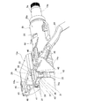
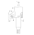
- FIG. 1 is a perspective view showing a first example of an embodiment of the present invention.
- FIG. 2 is a side view of the first example as viewed from the side of FIG.
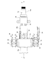
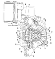
- FIG. 3 is a plan view of a first example shown in a state viewed from above in FIG. 4 is a cross-sectional view taken along the line AA in FIG. 5 is a cross-sectional view taken along the line BB in FIG.
- FIG. 6 is a perspective view seen from the same direction as FIG. 1 in a state before the outer column and the spacer constituting the first example are combined.
- FIG. 7 is a perspective view seen from the same direction as FIG. 1 in a state where the outer column, the spacer, and the inner column constituting the first example are combined.
- FIG. 1 is a perspective view showing a first example of an embodiment of the present invention.
- FIG. 2 is a side view of the first example as viewed from the side of FIG.
- FIG. 3 is a plan view of a first example shown in
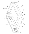
- FIG. 8 is a perspective view showing a state in which the spacer is taken out from the first example and seen from the rear and obliquely below.
- 9A is a plan view of the first example spacer as viewed from above
- FIG. 9B is a side view of the first example spacer from the side
- FIG. 9C is the first example spacer.
- FIG. 9D is an orthographic view of the first example spacer viewed from the front
- FIG. 9E is an orthographic view of the first example spacer viewed from the rear. It is.
- FIG. 10 is a perspective view showing two examples of the shape of the slit formed on the upper surface of the outer column, applied to the first example, with the front end portion of the outer column seen from slightly above FIG. .
- FIG. 10 is a perspective view showing two examples of the shape of the slit formed on the upper surface of the outer column, applied to the first example, with the front end portion of the outer column seen from slightly above FIG. .
- FIG. 11 is a view similar to FIG. 5, showing a second example of the embodiment of the present invention.
- FIG. 12 is a view similar to FIG. 6, showing a state before the outer column and the spacer constituting the second example are combined.
- FIG. 13 is a view similar to FIG. 7, showing a state in which the outer column, the spacer, and the inner column constituting the second example are combined.
- FIG. 14 is a view similar to FIG. 6, showing a third example of the embodiment of the present invention.
- FIG. 15 is a view similar to FIG. 7, showing a state in which the outer column, the spacer, and the inner column constituting the third example are combined.
- FIG. 16 is a view similar to FIG. 6, showing a fourth example of the embodiment of the present invention.
- FIG. 17 is a view similar to FIG.
- FIG. 18 is a partially cut side view showing an example of a conventionally known steering device.
- FIG. 19 is a partially cutaway schematic side view showing an example of a steering column provided with a steering column integrally provided with a swing support bracket portion.
- 20 is a cross-sectional view taken along the line CC of FIG.
- the steering column 6b of this example is a telescopic steering configured by fitting a front end portion of an outer column 20a, each of which is cylindrical, and a rear end portion of an inner column 19a so as to allow relative displacement in the axial direction. It is a column.
- the steering shaft 5a is rotatably supported by a bearing 27 such as a single row deep groove type ball bearing inside the steering column 6b.
- the steering shaft 5a is capable of transmitting torque and extending and contracting its entire length by spline-engaging the rear end portion of the circular inner shaft 17a and the front end portion of the circular outer shaft 18a. It is configured.
- locking part 28 for latching a suspension spring is provided in the outer surface of the outer column 20a.
- a key lock collar 29 constituting a steering lock device is externally fitted to an intermediate portion of the outer shaft 18a.
- the sandwiched bracket portion 30 is disposed at the front end portion of the outer column 20a and the rear end portion of the inner column 19a is fitted, for example, a metal plate constituting the outer column 20a. It is formed integrally with the outer column 20a by a hydroforming method that bulges radially outward.
- the sandwiched bracket portion 30 is provided in a state of protruding upward from the front end portion of the outer column 20a, and includes a pair of sandwiched plate portions 31 and a top plate portion 32.
- the pair of sandwiched plate portions 31 are provided in a state of being continuous upward from the main body portion of the outer column 20a, and are parallel to each other.
- the top plate part 32 is provided in a state in which the upper end edges of the pair of left and right sandwiched plate parts 31 are continuous. Therefore, the clamped bracket portion 30 has a box shape in which the lower side and the front side are opened.
- the processing method of the to-be-clamped bracket part 30 is not restricted to a hydroform construction method, Processing methods, such as press processing, bulge processing, vacuum forming, air blow molding, and explosive molding, can also be used.
- a pair of through-holes 33 are formed in portions of the sandwiched plate portion 31 that are aligned with each other.
- the through holes 33 are for inserting the rods 15 constituting the expansion / contraction mechanism that expands / contracts the gap between the sandwiched plate portions 31, and each includes a longitudinally long hole portion 34, a pair of notch portions 35, and the like. Consists of Of these, the longitudinal hole 34 is long in the axial direction of the outer column 20a. Moreover, the notch part 35 is provided in the state which protrudes below from the front-back direction both ends of the front-back direction long hole part 34, respectively.
- a slit 36 is provided at the center in the width direction of the upper surface of the front end portion of the outer column 20a to reduce the force required to reduce the inner diameter of the front end portion of the outer column 20a.
- a shape that does not open to the front edge of the outer column 20a can be used.
- a shape that opens to the front end edge of the outer column 20a may be employed. If it is not necessary to reduce the force, the slit can be omitted.
- the spacer 37 is assembled to the inner portion of the clamped bracket portion 30 at the front end portion of the outer column 20a.
- the spacer 37 is formed by injection molding synthetic resin, and is provided with a rectangular substrate portion 38 and a pair of parallel hanging plates provided in a state of hanging downward from the left and right end portions of the lower surface of the substrate portion 38. Part 39.
- Long holes 40 that are long in the front-rear direction are provided in portions of the pair of hanging plate portions 39 that are aligned with each other.
- the long hole 40 is provided at a position aligned with the longitudinal hole 34 in the front-rear direction of the through hole 33 formed in the sandwiched plate 31 in a state where the spacer 37 is assembled inside the sandwiched bracket 30.
- the upper edge (the inner peripheral surface upper side portion) of the longitudinal direction long hole portion 34 is positioned on the same plane as the lower surface of the substrate portion 38.
- the width dimension in the vertical direction and the length dimension in the front-rear direction of the long hole 40 are slightly smaller than the width dimension in the vertical direction and the length dimension in the front-rear direction of the front-rear direction long hole portion 34.
- the inner periphery of the long hole 40 is located in the width direction center part and the length direction center part side rather than the inner periphery of the front-back direction long hole part 34. , Projecting little by little.
- the long hole 40 and the longitudinally long hole portion 34 are inserted with a rod 15 for expanding and reducing the distance between the pair of right and left sandwiching plate portions 14a constituting the sandwiching bracket 13a supported on the vehicle body side.
- the outer peripheral surface of the rod 15 is in contact with the inner peripheral edge of the long hole 40 and the lower surface of the substrate portion 38.
- the inner peripheral edge (upper edge, lower edge, front edge and rear edge) of the longitudinal hole 34 is not contacted.
- the convex portion 41 is formed on the upper surface of the substrate portion 38, and the left and right outer surfaces of the hanging plate portion 39 are part of both the front and rear direction ends of the long hole 40.
- Locking protrusions 42 are provided on the lower portions, respectively.
- the convex part 41 is provided in a state protruding slightly upward from the central part in the width direction of the substrate part 38.
- the locking projections 42 have shapes and sizes that fit almost without gaps except for the cutouts 35 formed at the front and rear ends of the through-hole 33 and a slight gap caused by manufacturing errors. Have.
- a front holding plate portion 43 and a rear holding plate portion 44 are formed on both front and rear end portions of the lower surface of the substrate portion 38 so as to protrude downward.
- the lower end surface of the front holding plate portion 43 is a partially arcuate concave curved surface
- the lower end surface of the rear holding plate portion 44 is a flat surface.
- the lower end surfaces of the front holding plate portion 43 and the rear holding plate portion 44 are rear end portions of the inner column 19a in the assembled state of the steering column device, as shown in FIGS. Abuts or faces the outer peripheral surface (upper surface). And the bending rigidity of the fitting part of the rear-end part of the inner column 19a and the front-end part of the outer column 20a is improved.
- the spacer 37 elastically expands the interval between the sandwiched plate portions 31 inside the sandwiched bracket portion 30 and elastically deforms the center portion in the width direction of the top plate portion 32 upward, and The spacer 37 is pushed into the clamped bracket portion 30 in a state of being elastically deformed so as to be contracted in the width direction. Thereby, the latching convex part 42 and the notch part 35 engage. In this state, the lower surface of the locking convex portion 42 is elastically pressed against the lower end edge of the cutout portion 35, and the upper surface of the convex portion 41 is elastically pressed against the lower surface of the top plate portion 32.
- the outer side surface of the hanging plate portion 39 is elastically brought into contact with the inner side surface of the sandwiched plate portion 31.
- the convex portion 41 and the locking convex portion 42 press the lower surface of the top plate portion 32 and the locking notch portion 35 in the vertical direction.
- the hanging plate portion 39 presses the sandwiched plate portion 31 in the left-right direction.
- the spacer 37 is held on the inner side of the sandwiched bracket portion 30 without rattling in any of the upper, lower, left, and right directions.
- the telescopic steering column 6b is formed by combining the outer column 20a, which holds and fixes the spacer 37 inside the sandwiched bracket portion 30, with the inner column 19a. Further, the sandwiched bracket portion 30 of the steering column 6b is supported between the pair of left and right sandwiching plate portions 14a constituting the sandwiching bracket 13a so that the vertical position and the front and rear position can be adjusted.
- a pair of left and right mounting plate portions 45 provided on the holding bracket 13a are attached to the vehicle body 11 (see FIG. 18) by a pair of locking capsules 46 and bolts or studs 47 (see FIG. 18). It is supported to be able to move forward at the time of the next collision.
- An energy absorbing member 48 for absorbing impact energy applied to the holding bracket 13a at the time of a secondary collision is provided between the locking capsule 46 and the mounting plate portion 45.
- the structure for displacing the holding bracket 13a forward while absorbing impact energy at the time of the secondary collision is the same as that of the conventional steering column device.
- the spacer 37 supports the sandwiched bracket portion 30 in any of the vertical and horizontal directions inside the sandwiched bracket portion 30, the strength and rigidity of the sandwiched bracket portion 30 are increased. Virtually secure. That is, even if the thin sandwiched bracket portion 30 is strongly sandwiched by the pair of sandwiching plate portions 14a, the sandwiched bracket portion 30 is not easily deformed due to the presence of the spacer 37. Therefore, in order to hold the steering wheel 1 (see FIG. 18) in the adjusted position, the holding bracket portion 30 is held between the holding plate portions 14a by the functions of the adjusting handle 24, the cam device 25, and the rod 15.
- the clamped bracket portion 30 is prevented from being excessively deformed in the direction of reducing the width dimension.
- the contact pressure between the left and right outer surfaces of the sandwiched bracket portion 30 and the left and right inner surfaces of the sandwiching plate portion 14a can be sufficiently increased, and the support strength of the outer column 20a by the sandwiching bracket 13a and further the steering wheel 1 Sufficient holding strength for holding the vertical position at the adjusted position can be secured.
- the rear end portion of the inner column 19a is fitted into the front end portion of the outer column 20a provided with the sandwiched bracket portion 30.
- the width dimension of the clamped bracket portion 30 is necessary to reduce the width dimension of the clamped bracket portion 30 to some extent in order to reduce the inner diameter of the front end portion of the outer column 20a. Since there are gaps between the left and right end portions of the front side restraint plate portion 43 and the rear side restraint plate portion 44 provided on the front and rear end portions of the spacer 37 and the drooping plate portion 39, The interval can be reduced elastically to some extent.
- the width dimension of the clamped bracket portion 30 and the inner diameter of the front end portion of the outer column 20a can be reduced by a necessary amount, and the inner peripheral surface of the front end portion of the outer column 20a and the outer periphery of the rear end portion of the inner column 19a.
- the contact pressure with the surface can be made sufficiently high. As a result, it is possible to sufficiently secure the fitting strength of the outer column 20a with respect to the inner column 19a and also the holding strength for holding the front and rear positions of the steering wheel 1 at the adjusted positions.
- the clamped bracket portion 30 is not easily deformed. For this reason, it is easy to stabilize the behavior of the outer column 20a even while an impact load is applied, which is advantageous in terms of driver protection.
- the upper edge of the longitudinal slot 34 is located on the same plane as the lower surface of the substrate 38, and the upper end of the outer peripheral surface of the rod 15 is the upper edge of the longitudinal slot 40 and the substrate 38.
- the lower surface of the spacer 37 abuts over almost the entire width of the spacer 37. For this reason, even during a secondary collision, a large load is not locally applied to the portion in contact with the outer peripheral surface of the rod 15, and the spacer 37 and the sandwiched bracket portion 30 housing the spacer 37 are not easily deformed.
- the inner peripheral edge of the through-hole 33 formed in the metal clamped bracket portion 30 does not contact the outer peripheral surface of the rod 15 made of hard metal such as tool steel.
- the outer peripheral surface of the rod 15 contacts the inner peripheral edge of the long hole 40 formed in the synthetic resin spacer 37.
- FIG. 11 to 13 show a second example of the embodiment of the present invention.
- the clamped bracket portion 30a is formed to bulge downward from the outer column 20b, contrary to the case of the first example of the embodiment, at the front end portion of the outer column 20b. That is, the sandwiched bracket portion 30 a is configured by connecting the lower end portions of the pair of sandwiched plate portions 31 a on the left and right sides with the bottom plate portion 49. And the through-hole 33 which each consists of the longitudinal direction long hole part 34 and the notch part 35 is provided in the to-be-clamped plate part 31a in the state which made the up-down direction reverse direction with the 1st example of embodiment. Yes.
- the cutout portion 35 protrudes upward from both front and rear direction ends of the front and rear direction long hole portion 34.
- the spacer 37 similar to the 1st example of embodiment is assembled
- the convex portion 41 (see FIGS. 6 and 9) abuts on the upper surface of the bottom plate portion 49.
- the configuration and operation other than the fact that the vertical direction of the portion where the clamped bracket portion 30a is formed with respect to the outer column 20b is reversed is the same as in the first example of the embodiment.
- FIG. 14 and 15 show a third example of the embodiment of the present invention.
- the structure of this example shows a case where the present invention is applied to a structure having only a tilt function, omitting the telescopic function for adjusting the front-rear position of the steering wheel. That is, the end portion of the outer column 20c and the end portion of the inner column 19a are fitted so as not to allow relative displacement in the axial direction.
- the telescopic mechanism is omitted, and in the case of this example, the through holes formed in the pair of left and right sandwiched plate portions 31b are aligned with each other in the middle portion in the front-rear direction of the sandwiched plate portion 31b.
- a circular hole 50 is formed.
- locking holes 51 for engaging the locking protrusions 42 of the spacer 37 are formed at portions near the front and rear ends of the sandwiched plate portion 31b and at portions slightly below the circular holes 50, respectively. .
- the spacer 37 combined with the outer column 20c can be the same as the first example and the second example of the embodiment, the cost can be reduced by sharing the parts.
- the insertion hole provided in the spacer may be a simple circular hole.
- the telescopic function is omitted, so that the rod 15 (see FIGS. 2, 4, 5 and 11) is also a through-hole (circular hole 50) when adjusting the position of the steering wheel. However, there is no significant displacement.
- this embodiment is the same as the first example of the embodiment except that the through hole is a simple circular hole 50.
- FIG. 16 and 17 show a fourth example of the embodiment of the present invention.
- the clamped bracket portion 30b is formed to protrude downward on the front end portion of the outer column 20d, contrary to the case of the third example of the embodiment. This is the same as the structure of the second example with respect to the first example of the embodiment.
- the configuration and operation other than the fact that the vertical direction of the formation portion of the clamped bracket portion 30b with respect to the outer column 20d is reversed is the same as in the third example of the embodiment.
Landscapes
- Engineering & Computer Science (AREA)
- Chemical & Material Sciences (AREA)
- Combustion & Propulsion (AREA)
- Transportation (AREA)
- Mechanical Engineering (AREA)
- Steering Controls (AREA)
Abstract
Description
図1~図10は、本発明の実施の形態の第1例を示している。本例のステアリングコラム6bは、それぞれが筒状であるアウタコラム20aの前端部とインナコラム19aの後端部とを、軸方向の相対変位を可能に嵌合させることにより構成される、テレスコピックステアリングコラムである。そして、ステアリングコラム6bの内側にステアリングシャフト5aを、単列深溝型の玉軸受などの軸受27により、回転自在に支持している。ステアリングシャフト5aは、円杆状のインナシャフト17aの後端部と、円管状のアウタシャフト18aの前端部とをスプライン係合させることにより、トルクの伝達を可能に、かつ、全長の伸縮を可能に構成されている。なお、アウタコラム20aの外面には、吊り合いばねを係止するための係止部28を設けている。また、アウタシャフト18aの中間部に、ステアリングロック装置を構成するキーロックカラー29を外嵌している。なお、これらの構造およびその効果は、従来のステアリングコラム装置のものと同様である。
図11~図13は、本発明の実施の形態の第2例を示している。本例の場合には、アウタコラム20bの前端部に被挟持ブラケット部30aを、実施の形態の第1例の場合とは逆に、アウタコラム20bの下方に向けて膨出形成している。すなわち、被挟持ブラケット部30aは、左右1対の被挟持板部31aの下端部同士を、底板部49により連続させることにより構成される。そして、被挟持板部31aに、それぞれ前後方向長孔部34と切り欠き部35とからなる透孔33を、実施の形態の第1例とは、上下方向を逆向きにした状態で設けている。すなわち、切り欠き部35は、前後方向長孔部34の前後方向両端から上方に突出する。そして、被挟持ブラケット部30aの内側に、実施の形態の第1例と同様のスペーサ37を、上下方向を逆向きにした状態で組み付けている。凸部41(図6、図9参照)は、底板部49の上面に当接する。アウタコラム20bに対する被挟持ブラケット部30aの形成箇所などの上下方向が逆になったこと以外の構成および作用は、実施の形態の第1例と同様である。
図14および図15は、本発明の実施の形態の第3例を示している。本例の構造は、本発明を、ステアリングホイールの前後位置を調節するためのテレスコピック機能を省略し、チルト機能のみを備えた構造に適用する場合について示している。すなわち、アウタコラム20cの端部とインナコラム19aの端部とを、軸方向の相対変位を不能に嵌合させている。そして、テレスコピック機構を省略したことに伴って、本例の場合には、左右1対の被挟持板部31bに形成した透孔を、被挟持板部31bの前後方向中間部の互いに整合する部分に形成された、円孔50としている。また、被挟持板部31bの前後両端寄り部分で、円孔50よりも少し下寄り部分に、スペーサ37の係止凸部42を係合させるための係止孔51を、それぞれ形成している。このようなアウタコラム20cと組み合わせるスペーサ37は、実施の形態の第1例および第2例と同様のものを使用することができるため、部品の共用により低コスト化を図ることができる。ただし、スペーサに設ける挿通孔を、単なる円孔とすることもできる。なお、本例の場合には、テレスコピック機能を省略したことに伴い、ステアリングホイールの位置調節時にも、ロッド15(図2、図4、図5および図11参照)が透孔(円孔50)に対し大きく変位することはない。したがって、ロッド15の外周面と透孔(円孔50)の周縁との擦れ合い防止のための配慮は不要である。テレスコピック機能を省略したことに伴い、透孔を単なる円孔50とした点以外は、実施の形態の第1例と同様である。
図16および図17は、本発明の実施の形態の第4例を示している。本例の場合には、アウタコラム20dの前端部に被挟持ブラケット部30bを、実施の形態の第3例の場合とは逆に、下側に向けて突出形成している。この点に関しては、実施の形態の第1例に対する第2例の構造の場合と同様である。アウタコラム20dに対する被挟持ブラケット部30bの形成箇所などの上下方向が逆になったこと以外の構成および作用は、実施の形態の第3例と同様である。
2 ステアリングギヤユニット
3 入力軸
4 タイロッド
5、5a ステアリングシャフト
6、6a、6b ステアリングコラム
7 自在継手
8 中間シャフト
9 自在継手
10、10a 横軸
11、11a 車体
12 被挟持ブラケット
13、13a 挟持ブラケット
14、14a 挟持板部
15 ロッド
16 上下方向長孔
17、17a インナシャフト
18、18a アウタシャフト
19、19a インナコラム
20、20a、20b、20c、20d アウタコラム
21 前後方向長孔
22 頭部
23 押圧駒
24 調節ハンドル
25 カム装置
26 揺動支持ブラケット部
27 軸受
28 係止部
29 キーロックカラー
30、30a、30b 被挟持ブラケット部
31、31a、31b 被挟持板部
32 天板部
33 透孔
34 前後方向長孔部
35 切り欠き部
36 スリット
37 スペーサ
38 基板部
39 垂下板部
40 長孔
41 凸部
42 係止凸部
43 前側抑え板部
44 後側抑え板部
45 取付板部
46 係止カプセル
47 ボルト若しくはスタッド
48 エネルギ吸収部材
49 底板部
50 円孔
51 係止孔
Claims (5)
- 筒状のインナコラムと、
筒状で、その端部が前記インナコラムの端部に嵌合したアウタコラムと、
前記インナコラムの端部と嵌合した前記アウタコラムの端部に、当該アウタコラムを構成する金属板を径方向外方に膨出させることにより、当該アウタコラムと一体に形成され、互いに平行な左右1対の被狭持板部と、当該被狭持板部の互いに整合する部分に、当該被狭持板部同士の間隔を拡縮するためのロッドを挿通するための1対の透孔とを備える、被狭持ブラケット部と、
前記アウタコラムを構成する金属板よりも軟質な材料により形成され、前記透孔に整合する部分に、前記ロッドを挿通するための挿通孔を備え、前記被狭持ブラケット部の内側で前記被狭持板部同士の間に組み付けられる、スペーサと、
を備えるステアリングコラム装置。 - 前記アウタコラムの端部は、前記インナコラムの端部と軸方向の相対変位を可能に嵌合しており、
前記被狭持ブラケット部は、前記アウタコラムの端部から上方に突出する状態で設けられており、
前記透孔はそれぞれ、前記アウタコラムの軸方向に長い前後方向長孔部と、当該前後方向長孔部の前後方向両端部からそれぞれ下方に向け突出する状態で設けられた、1対の切り欠き部とにより構成されており、
前記挿通孔は、前記透孔のうちの前記前後方向長孔部に整合する部分に設けられた、前後方向に長く、かつ、その上下方向に関する幅寸法が前記前後方向長孔部の上下方向に関する幅寸法よりも小さい長孔により構成されており、
前記スペーサの左右の外側面の一部で前記長孔の前後方向両端部の下側部分に、前記切り欠き部と嵌合する係止凸部が設けられており、
前記スペーサの上面を前記被挟持ブラケット部の内面に当接させ、かつ、前記係止凸部を前記切り欠き部にそれぞれ係合させた状態で、前記挿通孔の上縁および下縁を、前記前後方向長孔部の上縁および下縁よりも、前記挿通孔および前記前後方向長孔部の幅方向に関して内側に存在させ、前記挿通孔および前記前後方向長孔部に挿通した前記ロッドの外周面が、前記前後方向長孔部の内周縁と接触しないようになっている、請求項1に記載のステアリングコラム装置。 - 前記アウタコラムの端部は、前記インナコラムの端部と軸方向の相対変位を可能に嵌合しており、
前記被狭持ブラケット部は、前記アウタコラムの端部から下方に突出する状態で設けられており、
前記透孔はそれぞれ、前記アウタコラムの軸方向に長い前後方向長孔部と、当該前後方向長孔部の前後方向両端部からそれぞれ上方に向け突出する状態で設けられた、1対の切り欠き部とにより構成されており、
前記挿通孔は、前記透孔のうちの前記前後方向長孔部に整合する部分に設けられた、前後方向に長く、かつ、その上下方向に関する幅寸法が前記前後方向長孔部の上下方向に関する幅寸法よりも小さい長孔により構成されており、
前記スペーサの左右の外側面の一部で前記長孔の前後方向両端部の上側部分に、前記切り欠き部と嵌合する係止凸部が設けられており、
前記スペーサの下面を前記被挟持ブラケット部の内面に当接させ、かつ、前記係止凸部を前記切り欠き部にそれぞれ係合させた状態で、前記挿通孔の上縁および下縁を、前記前後方向長孔部の上縁および下縁よりも、前記挿通孔および前記前後方向長孔部の幅方向に関して内側に存在させ、前記挿通孔および前記前後方向長孔部に挿通した前記ロッドの外周面が、前記前後方向長孔部の内周縁と接触しないようになっている、請求項1に記載のステアリングコラム装置。 - 前記被狭持ブラケット部は、前記アウタコラムの端部から上方に突出する状態で設けられ、かつ、前記被狭持板部の前端寄り部分と後端寄り部分とに、それぞれ係止孔が設けられており、
前記透孔はそれぞれ、前記被狭持板部の前後方向中間部の互いに整合する部分に形成された円孔により構成されており、
前記挿通孔は、少なくとも一部が前記透孔に整合する部分に設けられており、
前記スペーサの左右の外側面の一部で、それぞれ前記係止孔と整合する部分に、前記係止孔と係合する係止凸部が設けられており、
前記スペーサの上面を前記被狭持ブラケット部の内面に当接させ、かつ、前記係止凸部を前記係止孔に係合させている、請求項1に記載のステアリングコラム装置。 - 前記被狭持ブラケット部は、前記アウタコラムの端部から下方に突出する状態で設けられ、かつ、前記被狭持板部の前端寄り部分と後端寄り部分とに、それぞれ係止孔が設けられており、
前記透孔はそれぞれ、前記被狭持板部の前後方向中間部の互いに整合する部分に形成された円孔により構成されており、
前記挿通孔は、少なくとも一部が前記透孔に整合する部分に設けられており、
前記スペーサの左右の外側面の一部で、それぞれ前記係止孔と整合する部分に、前記係止孔と係合する係止凸部設けられており、
前記スペーサの下面を前記被狭持ブラケット部の内面に当接させ、かつ、前記係止凸部を前記係止孔に係合させている、請求項1に記載のステアリングコラム装置。
Priority Applications (3)
| Application Number | Priority Date | Filing Date | Title |
|---|---|---|---|
| EP12838491.4A EP2716520B1 (en) | 2011-10-03 | 2012-09-26 | Steering column device |
| CN201280001480.2A CN103153751B (zh) | 2011-10-03 | 2012-09-26 | 转向柱装置 |
| US14/130,066 US9108672B2 (en) | 2011-10-03 | 2012-09-26 | Steering column apparatus |
Applications Claiming Priority (2)
| Application Number | Priority Date | Filing Date | Title |
|---|---|---|---|
| JP2011-218971 | 2011-10-03 | ||
| JP2011218971A JP5609838B2 (ja) | 2011-06-16 | 2011-10-03 | ステアリングコラム装置 |
Publications (1)
| Publication Number | Publication Date |
|---|---|
| WO2013051441A1 true WO2013051441A1 (ja) | 2013-04-11 |
Family
ID=48045198
Family Applications (1)
| Application Number | Title | Priority Date | Filing Date |
|---|---|---|---|
| PCT/JP2012/074664 Ceased WO2013051441A1 (ja) | 2011-10-03 | 2012-09-26 | ステアリングコラム装置 |
Country Status (5)
| Country | Link |
|---|---|
| US (1) | US9108672B2 (ja) |
| EP (1) | EP2716520B1 (ja) |
| JP (1) | JP5609838B2 (ja) |
| CN (1) | CN103153751B (ja) |
| WO (1) | WO2013051441A1 (ja) |
Cited By (1)
| Publication number | Priority date | Publication date | Assignee | Title |
|---|---|---|---|---|
| US20180229754A1 (en) * | 2015-09-29 | 2018-08-16 | Nsk Ltd. | Position adjusting apparatus for steering wheel |
Families Citing this family (10)
| Publication number | Priority date | Publication date | Assignee | Title |
|---|---|---|---|---|
| US9283982B2 (en) * | 2011-11-03 | 2016-03-15 | Namyang Ind. Co., Ltd. | Steering column |
| EP2915721B1 (en) * | 2013-01-30 | 2018-10-03 | NSK Ltd. | Steering column |
| WO2015133017A1 (ja) * | 2014-03-03 | 2015-09-11 | 日本精工株式会社 | テレスコピックステアリング装置用アウタコラム及びテレスコピックステアリング装置 |
| DE102014110204B3 (de) * | 2014-07-21 | 2015-10-01 | Thyssenkrupp Presta Ag | Lenksäule für ein Kraftfahrzeug |
| WO2016114366A1 (ja) | 2015-01-14 | 2016-07-21 | 日本精工株式会社 | ステアリング装置 |
| WO2016186144A1 (ja) * | 2015-05-19 | 2016-11-24 | 日本精工株式会社 | テレスコピック式ステアリング装置 |
| JP6731229B2 (ja) * | 2015-10-16 | 2020-07-29 | 株式会社山田製作所 | ステアリング装置及びその製造方法 |
| DE102016205378B3 (de) * | 2016-03-31 | 2017-05-11 | Thyssenkrupp Ag | Lenksäule für ein Kraftfahrzeug |
| EP3511225B1 (en) * | 2018-01-10 | 2020-11-25 | Volvo Car Corporation | A steering arrangement |
| KR20220068781A (ko) * | 2020-11-19 | 2022-05-26 | 주식회사 만도 | 스티어링 칼럼 및 이를 포함하는 스티어링 장치 |
Citations (5)
| Publication number | Priority date | Publication date | Assignee | Title |
|---|---|---|---|---|
| JPH08207787A (ja) * | 1995-02-03 | 1996-08-13 | Nippon Seiko Kk | ステアリングコラムの支持装置 |
| JPH08216895A (ja) * | 1995-02-17 | 1996-08-27 | Nissan Motor Co Ltd | ステアリングコラム支持装置 |
| JP2002046621A (ja) * | 2000-08-02 | 2002-02-12 | Nsk Ltd | 車両用ステアリング装置 |
| JP2002249052A (ja) * | 2001-02-26 | 2002-09-03 | Koyo Seiko Co Ltd | ステアリング装置 |
| JP2008296754A (ja) * | 2007-05-31 | 2008-12-11 | Nsk Ltd | 位置調整式ステアリング装置 |
Family Cites Families (4)
| Publication number | Priority date | Publication date | Assignee | Title |
|---|---|---|---|---|
| US7093855B2 (en) * | 2003-12-05 | 2006-08-22 | Delphi Technologies, Inc. | Steering column assembly having clamping mechanism |
| US7827880B2 (en) * | 2005-03-21 | 2010-11-09 | Gm Global Technology Operations, Inc. | Steering column assembly with a quick release bolt |
| JP5305005B2 (ja) * | 2007-02-13 | 2013-10-02 | 日本精工株式会社 | ステアリングコラム装置 |
| JP5279741B2 (ja) * | 2009-03-30 | 2013-09-04 | 株式会社山田製作所 | ステアリング装置 |
-
2011
- 2011-10-03 JP JP2011218971A patent/JP5609838B2/ja active Active
-
2012
- 2012-09-26 CN CN201280001480.2A patent/CN103153751B/zh not_active Expired - Fee Related
- 2012-09-26 EP EP12838491.4A patent/EP2716520B1/en not_active Not-in-force
- 2012-09-26 US US14/130,066 patent/US9108672B2/en active Active
- 2012-09-26 WO PCT/JP2012/074664 patent/WO2013051441A1/ja not_active Ceased
Patent Citations (5)
| Publication number | Priority date | Publication date | Assignee | Title |
|---|---|---|---|---|
| JPH08207787A (ja) * | 1995-02-03 | 1996-08-13 | Nippon Seiko Kk | ステアリングコラムの支持装置 |
| JPH08216895A (ja) * | 1995-02-17 | 1996-08-27 | Nissan Motor Co Ltd | ステアリングコラム支持装置 |
| JP2002046621A (ja) * | 2000-08-02 | 2002-02-12 | Nsk Ltd | 車両用ステアリング装置 |
| JP2002249052A (ja) * | 2001-02-26 | 2002-09-03 | Koyo Seiko Co Ltd | ステアリング装置 |
| JP2008296754A (ja) * | 2007-05-31 | 2008-12-11 | Nsk Ltd | 位置調整式ステアリング装置 |
Non-Patent Citations (1)
| Title |
|---|
| See also references of EP2716520A4 * |
Cited By (1)
| Publication number | Priority date | Publication date | Assignee | Title |
|---|---|---|---|---|
| US20180229754A1 (en) * | 2015-09-29 | 2018-08-16 | Nsk Ltd. | Position adjusting apparatus for steering wheel |
Also Published As
| Publication number | Publication date |
|---|---|
| EP2716520A4 (en) | 2015-03-18 |
| EP2716520B1 (en) | 2016-08-17 |
| US9108672B2 (en) | 2015-08-18 |
| JP2013018472A (ja) | 2013-01-31 |
| EP2716520A1 (en) | 2014-04-09 |
| JP5609838B2 (ja) | 2014-10-22 |
| CN103153751B (zh) | 2016-04-06 |
| US20140318302A1 (en) | 2014-10-30 |
| CN103153751A (zh) | 2013-06-12 |
Similar Documents
| Publication | Publication Date | Title |
|---|---|---|
| WO2013051441A1 (ja) | ステアリングコラム装置 | |
| US10093341B2 (en) | Steering device | |
| US9604661B2 (en) | Steering column apparatus | |
| WO2012063609A1 (ja) | ステアリングコラム用支持装置 | |
| WO2012157702A1 (ja) | 自動車用ステアリング装置 | |
| JP6796255B2 (ja) | ステアリング装置 | |
| CN112930296B (zh) | 转向柱装置 | |
| JP2017197032A (ja) | ステアリング装置 | |
| WO2004031018A1 (ja) | ステアリングコラム装置 | |
| WO2020116350A1 (ja) | ステアリング装置 | |
| JP5553005B2 (ja) | ステアリングコラム用支持装置 | |
| JP7310166B2 (ja) | ステアリングコラム装置 | |
| JP6080007B2 (ja) | ステアリングコラム装置 | |
| JP5742978B2 (ja) | ステアリングコラム装置 | |
| JP2013052846A (ja) | エンジンの支持構造 | |
| JP2014076806A5 (ja) | ||
| JP2017132323A (ja) | ステアリングホイールの位置調節装置 | |
| JP5737369B2 (ja) | ステアリングコラム用支持装置 | |
| JP2015074314A (ja) | ステアリング装置 | |
| JP5321634B2 (ja) | 自動車用ステアリングコラムの支持装置 | |
| JP5327191B2 (ja) | ステアリングコラム用支持装置 | |
| JP4696517B2 (ja) | 伸縮構造及び車両用ステアリングコラム装置 | |
| JP2017056820A (ja) | ステアリングホイールの位置調節装置 | |
| JP5327192B2 (ja) | ステアリングコラム用支持装置 | |
| KR100885106B1 (ko) | 자동차용 텔레스코픽 칼럼의 유격 흡수 구조 |
Legal Events
| Date | Code | Title | Description |
|---|---|---|---|
| WWE | Wipo information: entry into national phase |
Ref document number: 201280001480.2 Country of ref document: CN |
|
| 121 | Ep: the epo has been informed by wipo that ep was designated in this application |
Ref document number: 12838491 Country of ref document: EP Kind code of ref document: A1 |
|
| REEP | Request for entry into the european phase |
Ref document number: 2012838491 Country of ref document: EP |
|
| WWE | Wipo information: entry into national phase |
Ref document number: 2012838491 Country of ref document: EP |
|
| WWE | Wipo information: entry into national phase |
Ref document number: 14130066 Country of ref document: US |
|
| NENP | Non-entry into the national phase |
Ref country code: DE |