WO2013051480A1 - 圧着端子 - Google Patents
圧着端子 Download PDFInfo
- Publication number
- WO2013051480A1 WO2013051480A1 PCT/JP2012/075124 JP2012075124W WO2013051480A1 WO 2013051480 A1 WO2013051480 A1 WO 2013051480A1 JP 2012075124 W JP2012075124 W JP 2012075124W WO 2013051480 A1 WO2013051480 A1 WO 2013051480A1
- Authority
- WO
- WIPO (PCT)
- Prior art keywords
- conductor
- serration
- terminal
- conductor crimping
- crimping
- Prior art date
- Legal status (The legal status is an assumption and is not a legal conclusion. Google has not performed a legal analysis and makes no representation as to the accuracy of the status listed.)
- Ceased
Links
Images




Classifications
-
- H—ELECTRICITY
- H01—ELECTRIC ELEMENTS
- H01R—ELECTRICALLY-CONDUCTIVE CONNECTIONS; STRUCTURAL ASSOCIATIONS OF A PLURALITY OF MUTUALLY-INSULATED ELECTRICAL CONNECTING ELEMENTS; COUPLING DEVICES; CURRENT COLLECTORS
- H01R4/00—Electrically-conductive connections between two or more conductive members in direct contact, i.e. touching one another; Means for effecting or maintaining such contact; Electrically-conductive connections having two or more spaced connecting locations for conductors and using contact members penetrating insulation
- H01R4/10—Electrically-conductive connections between two or more conductive members in direct contact, i.e. touching one another; Means for effecting or maintaining such contact; Electrically-conductive connections having two or more spaced connecting locations for conductors and using contact members penetrating insulation effected solely by twisting, wrapping, bending, crimping, or other permanent deformation
- H01R4/18—Electrically-conductive connections between two or more conductive members in direct contact, i.e. touching one another; Means for effecting or maintaining such contact; Electrically-conductive connections having two or more spaced connecting locations for conductors and using contact members penetrating insulation effected solely by twisting, wrapping, bending, crimping, or other permanent deformation by crimping
- H01R4/188—Electrically-conductive connections between two or more conductive members in direct contact, i.e. touching one another; Means for effecting or maintaining such contact; Electrically-conductive connections having two or more spaced connecting locations for conductors and using contact members penetrating insulation effected solely by twisting, wrapping, bending, crimping, or other permanent deformation by crimping having an uneven wire-receiving surface to improve the contact
Definitions
- the present invention relates to an open barrel type crimp terminal having a concave serration on the inner surface of a conductor crimping portion having a U-shaped cross section.
- a conventional general crimp terminal includes, for example, an electrical connection portion, a conductor crimp portion, and a covering crimp portion as disclosed in Patent Document 1.
- the electrical connection portion is provided at the front portion in the longitudinal direction of the terminal (the same direction as the longitudinal direction of the conductor of the electric wire connected to the terminal), and is connected to the terminal on the mating connector side.
- the conductor crimping portion is provided behind the electrical connection portion in the longitudinal direction of the terminal and is crimped to the conductor exposed at the end of the electric wire.
- the covering crimping portion is provided behind the conductor crimping portion in the longitudinal direction of the terminal, and is crimped to a portion of the electric wire covered with insulation.
- the conductor crimping part has a substantially U-shaped cross section.
- the conductor crimping portion includes a bottom plate and a pair of conductor crimping pieces that extend upward from the left and right side edges of the bottom plate and are crimped so as to wrap the conductor of the electric wire disposed on the inner surface of the bottom plate.
- the coating caulking part is formed in a substantially U-shaped cross section.
- the coating caulking portion is a pair of coating caulking that extends upward from the left and right side edges of the bottom plate and wraps the electric wire (insulated coating portion) disposed on the inner surface of the bottom plate. And a piece.
- a plurality of concave groove-like serrations extending in a direction orthogonal to the direction in which the conductor of the electric wire extends (terminal longitudinal direction) is provided on the inner surface of the conductor crimping portion.
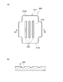
- FIG. 1A shows a developed shape of a conductor crimping portion of a conventional crimp terminal.
- the conductor crimping portion 213 of the crimp terminal 200 is a pair of conductors that are caulked so as to wrap around the bottom plate 215 and the electric wire conductors that extend upward from the left and right side edges of the bottom plate 215 and are disposed on the inner surface of the bottom plate 215. It is formed with crimping pieces 213a and 213a.
- FIG. 1A shows the developed shape of the conductor crimping portion, but actually, the conductor crimping portion 213 is bent into a substantially U-shaped cross section before the crimping.
- FIG. 1 (b) is a cross-sectional view taken along the line BB in FIG. 1 (a).
- the cross-sectional shape of the groove-shaped serration 220 is usually rectangular or inverted trapezoidal.
- the angle ⁇ formed by the extension surface of the inner bottom surface of the serration 220 and the inner surface is referred to as a serration angle.
- This serration angle ⁇ is generally set in the range of 45 ° to 90 °.
- the crimp terminal 200 In order to crimp the conductor crimping portion 213 of the crimp terminal 200 to the conductor (not shown) of the end of the electric wire, the crimp terminal 200 is placed on the mounting surface (upper surface) of the lower mold (anvil, not shown) and The conductor is inserted between the pair of conductor crimping pieces 213 a and 213 a of the conductor crimping portion 213 and placed on the upper surface of the bottom plate 215. Then, by lowering the upper die (clamper) relative to the lower die, the leading end side of the conductor crimping piece 213a is gradually brought down to the inside of the crimp terminal 200 on the guide slope of the upper die.
- the leading ends of the conductor crimping pieces 213a and 213a are folded back to the conductor side by a curved surface extending from the guide slope of the upper die to the central chevron. Rolled into the conductor of the wire while rubbing against each other. Thereby, the conductor crimping pieces 213a and 213a are crimped so as to enclose the conductor.
- the conductor crimping portion 213 of the crimp terminal 200 can be connected to the conductor of the electric wire by crimping.
- the conductor of the electric wire enters the serration 220 on the inner surface of the conductor crimping portion 213 while being plastically deformed by the applied pressure. Thereby, the electrical and mechanical joining of the terminal 200 and the electric wire is strengthened.
- An object of the present invention is to provide a crimp terminal capable of suppressing a change in serration angle (an angle formed by an extension surface of an inner bottom surface of a concave serration and an inner surface).
- the electrical connecting portion provided at the front portion in the terminal longitudinal direction and the rear portion from the electrical connecting portion in the terminal longitudinal direction are connected by crimping to the conductor at the end of the electric wire.
- a conductor crimping portion wherein the conductor crimping portion is formed in a substantially U-shaped cross section, and the conductor crimping portion extends upward from left and right side edges of the bottom plate, and the bottom plate
- a pair of conductor crimping pieces that are crimped so as to wrap the conductor of the electric wire disposed on the inner surface of the conductor, and a concave serration is provided on the inner surface of the conductor crimping portion, Before the conductor crimping portion is crimped to the conductor of the electric wire, a large number of circular recesses are provided on the inner surface of the conductor crimping portion so as to be spaced apart from each other.
- the bottom diameter is 0.15 (error range ⁇ 0. 4) It is set within the range of mm to 0.8 (error range ⁇ 0.04) mm, and the serration angle between the extended surface of the inner bottom surface and the inner surface of each circular recess is in the range of 60 ° to 90 °.
- the crimp terminal is characterized in that the shortest distance between the peripheral portions of the circular concave portions adjacent to each other and the flat portion between the peripheral portions is set to 0.17 (error range ⁇ 0.09) mm. To do.
- the diameter of the inner bottom surface of each circular recess is set to 0.3 (error range ⁇ 0.04) mm, and the extension surface and the inner surface of the inner bottom surface of the circular recess. Is set to 70 °, and the shortest distance between the peripheral edges of the circular recesses adjacent to each other is set to 0.15 mm.
- a large number of circular recesses are provided on the inner surface of the conductor crimping part as dotted serrations in a state of being separated from each other.
- the diameter of each circular recess is set within a range of 0.15 (error range ⁇ 0.04) mm to 0.8 (error range ⁇ 0.04) mm.
- the serration angle formed between the extended surface of the inner bottom surface of each circular recess and the inner surface is set within a range of 60 ° to 90 °.
- the shortest distance of the flat part between the periphery of the circular recessed part adjacent to each other is set to 0.17 (error range ⁇ 0.09) mm.
- the moment of inertia of the section where the serration is formed can be significantly increased compared to the case where the serration is formed by a rectangular recess or the case where the serration is formed by a groove having a rectangular section. it can. Therefore, when the sectional moment of inertia is increased, the inner surface of the circular recess is tilted and deformed at the time of crimping, that is, the serration angle in the state after crimping (which is formed by the extension surface of the inner bottom surface of each circular recess and the inner surface). Angle) can be kept small, and the engagement between the peripheral edge and inner surface of the circular recess and the conductor that undergoes plastic deformation can be strengthened.
- the deformation on the terminal side is reduced, the stress acting on the conductor (element wire) of the electric wire can be increased, and the relative sliding distance between the terminal and the conductor can be increased to increase the concentration of the terminal and the conductor.
- the amount of attachment can be increased, and the crimping performance (electrical and mechanical coupling performance) can be improved.
- the diameter of each circular recess is set to 0.3 (error range ⁇ 0.04) mm.
- the serration angle between the extended surface of the inner bottom surface of each circular recess and the inner surface is set to 70 °.
- the shortest distance of the plane part between the periphery of the circular recessed part which adjoins mutually is set to 0.15 mm. Therefore, the cross-sectional secondary moment of the serration portion can be effectively increased, and the deformation of the serration angle in the state after the crimping can be suppressed as small as possible.
- the stress acting on the conductor (element wire) of the electric wire can be increased, the relative sliding distance between the terminal and the conductor can be increased, and the crimping performance can be further improved. .
- FIG. 1A is a plan view showing a developed shape of a conductor crimping portion of a conventional crimp terminal
- FIG. 1B is a cross-sectional view taken along the line BB in FIG.
- FIG. 2 (a) is a characteristic diagram showing the relationship between the compression rate and the serration angle, comparing the case where the serration angle changes and the case where the serration angle does not change during crimping.
- FIG. 2B is a characteristic diagram showing the relationship between the compressibility and the stress acting on the conductor, comparing the case where the serration angle changes and the case where the serration angle does not change during crimping.
- FIG. 3 is an external perspective view of the crimp terminal according to the first embodiment of the present invention.
- FIG. 3 is an external perspective view of the crimp terminal according to the first embodiment of the present invention.
- FIG. 4 is a plan view showing a developed shape of the conductor crimping portion of the crimp terminal according to the first embodiment of the present invention.
- FIGS. 6A to 6D are enlarged cross-sectional views schematically showing the state in which the conductor enters the small circular concave portion of the conductor crimping portion while being plastically deformed during crimping.
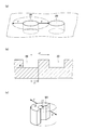
- 7A is a partially enlarged perspective view of a conductor crimping portion provided with a small circular recess, FIG.
- FIG. 7B is a cross-sectional view of the small circular recess
- FIG. It is a perspective view of the calculation model of the section secondary moment used for calculating the section secondary moment of the serration part of the conductor crimping part of a 1st embodiment of the present invention.
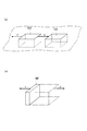
- FIG. 8A is a partially enlarged perspective view of a conductor crimping portion provided with a rectangular recess in the comparative example
- FIG. 8B is a sectional second moment of the serration portion of the conductor crimping portion in the comparative example.
- FIG. 9A is a diagram showing that stress is uniformly applied to the periphery of the small circular recess
- FIG. 9A is a diagram showing that stress is uniformly applied to the periphery of the small circular recess
- FIG. 9A is a diagram showing that stress is uniformly applied to the periphery of the small circular recess
- FIG. 9A is a diagram showing that stress is uniformly applied to the peripher
- FIG. 9B is that stress is applied unevenly to the periphery of the rectangular recess.
- FIG. 11A is a plan view showing a developed shape of the conductor crimping portion
- FIG. 11B is a cross-sectional view taken along the line AA in FIG. 11A.
- FIG. 3 is an external perspective view of the crimp terminal.
- FIG. 4 is a plan view showing a developed shape of the conductor crimping portion of the crimp terminal.
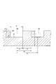
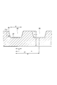
- FIG. 5 is an enlarged cross-sectional view of a small circular recess in a state before the crimping of the conductor crimping portion.
- FIGS. 6A to 6D are enlarged cross-sectional views schematically showing the state in which the conductor enters the small circular concave portion of the conductor crimping portion while being plastically deformed during crimping.
- the crimp terminal 10 is a female terminal, and includes an electrical connection portion 11, a connecting portion 12, a conductor crimp portion 13, and a covering crimp portion 14.
- the box-type electrical connection portion 11 is provided at the front of the terminal in the longitudinal direction (longitudinal direction of the conductor of the electric wire connected to the terminal, that is, the direction in which the electric wire extends), and is connected to the male terminal on the mating connector side.
- the conductor crimping part 13 is provided behind the electrical connection part 11 in the longitudinal direction of the terminal, and is crimped to the conductor Wa (see FIG. 6) exposed at the end of the electric wire (not shown).
- the covering crimping portion 14 is provided behind the conductor crimping portion 13 in the longitudinal direction of the terminal, and is crimped to a portion of the electric wire covered with insulation.
- the connecting portion 12 is provided between the electrical connecting portion 11 and the conductor crimping portion 13, and connects the electrical connecting portion 11 and the conductor crimping portion 13.
- the conductor crimping portion 13 is formed in a substantially U-shaped cross section.
- the conductor crimping portion 13 includes a bottom plate 15 extending from the electrical connection portion 11 to the covering crimping portion 14, and a conductor of an electric wire that extends upward from the left and right side edges of the bottom plate 15 and is disposed on the inner surface of the bottom plate 15. And a pair of conductor crimping pieces 13a and 13a for crimping so as to wrap the wire.
- the cover crimping portion 14 is fastened so as to wrap the bottom plate 15 and the electric wires (insulation-coated portions) that extend upward from the left and right side edges of the bottom plate 15 and are arranged on the inner surface of the bottom plate 15. It has a pair of covering crimping pieces 14a, 14a.
- each small circular recess 20 is rectangular.
- the inner bottom surface 21 of the recess 20 is formed substantially parallel to the surface of the conductor crimping portion 13 where the recess 20 is not formed.
- the serration (small circular concave portion 20) of the conductor crimping portion 13 is manufactured by pressing with a mold having a large number of cylindrical convex portions corresponding to the concave portion 20.
- a radius of an appropriate size is provided at the inner peripheral corner where the inner side surface 22 of the recess 20 as the serration intersects the inner bottom surface 21 and the peripheral edge of the recess 20.
- the material of the crimp terminal 10 is a copper alloy or the like, and the surface of the material is plated.
- each small circular recess 20 is 0.3 (error range ⁇ 0.04) mm (that is, the diameter is 0.26 to 0.34 mm, and the radius r1 is 0. 0). 13 to 0.17 mm).
- the depth h of each small circular recess 20 is set to 0.05 (error range ⁇ 0.02) mm.
- the serration angle ⁇ between the extended surface 21a of the inner bottom surface 21 of each small circular recess 20 and the inner side surface 22 is set to 60 ° to 90 ° (90 ° in this embodiment).
- the shortest distance b of the plane portion between the peripheral edges of the small circular recesses 20 adjacent to each other is set to 0.17 (error range ⁇ 0.09) mm (that is, 0.08 to 0.26 mm). Yes.
- the pitch P of the small circular recesses 20 is set to 0.47 (error range ⁇ 0.05) mm (that is, 0.42 to 0.52 mm).
- the crimping terminal 10 In order to crimp the conductor crimping portion 13 of the crimping terminal 10 to the conductor Wa (see FIG. 6) of the end of the electric wire, the crimping terminal 10 is placed on the mounting surface (upper surface) of the lower mold (anvil, not shown), The conductor Wa at the end of the electric wire is inserted between the conductor crimping pieces 13a of the conductor crimping portion 13 and placed on the upper surface of the bottom plate 15 (the inner surface that becomes the inner side when rolled). In this case, the conductor Wa of the electric wire is formed as a wire by twisting a large number of strands Wt.
- the material of the conductor Wa is copper or aluminum (including an alloy).
- the upper mold (clamper) With the conductor Wa set on the lower mold, the upper mold (clamper) is lowered relative to the lower mold, thereby gradually moving the tip side of the pair of conductor crimping pieces 13a, 13a on the upper mold guide slope. Go down inside. Further, when the upper die (clamper) is lowered relative to the lower die, the ends of the conductor crimping pieces 13a and 13a are folded back to the conductor side by a curved surface extending from the guide slope of the upper die to the central chevron. And bite into the conductor Wa of the electric wire while rubbing against each other. Thereby, the conductor crimping pieces 13a and 13a are crimped so as to enclose the conductor Wa. *
- the conductor crimping portion 13 of the crimp terminal 10 can be connected to the conductor Wa of the electric wire by crimping.
- the covering crimping portion 14 is gradually bent inward using the lower mold and the upper mold so that the covering crimping pieces 14a and 14a are formed on the insulation-coated portions of the electric wires. Clamp. Thereby, the crimp terminal 10 can be electrically and mechanically connected to the electric wire.
- the conductor Wa gradually enters the small recess 20 while being plastically deformed.
- the recesses 20 are filled while the conductor Wa smoothly flows along the inner surface.
- the contact pressure by the conductor Wa with respect to the peripheral edge of the recess 20 gradually increases as the pressing force increases, and the force due to the contact pressure increases the force of the recess 20. Trying to deform the periphery outward.
- the recess 20 is formed in a circular shape in plan view, and the dimensions of the recess 20 and its peripheral dimensions are set as described above, so the rigidity of the portion where the recess 20 is provided.
- it is significantly higher than the conventional grooved serration. Thereby, the deformation of the recess 20, particularly the deformation of the serration angle ⁇ is suppressed.
- a small circular recess 20 (sometimes referred to as circular serration or round serration), for example, a direction in which the serration angle ⁇ of the recess 20 is reduced by the pressure applied during crimping.
- the force F acts on.
- the peripheral wall portion of the concave portion 20 can be regarded as a semi-cylindrical model M1. Therefore, the cross-sectional second moment in the model M1 is calculated.
- the cross-sectional secondary moment I of the semi-cylindrical member can be obtained from the following formula (Formula 1).
- r1 is a radius of the small circular recessed part 20, and is an internal diameter of a semicircular arc shaped member.
- R2 is a dimension obtained by adding the length b of the flat portion to r1, and is the outer diameter of the semi-cylindrical member in cross section.
- the second moment of section was calculated when a rectangular recess 120 was provided as a concave serration.
- the portion that receives the applied pressure can be viewed as a model M2 of a planar wall.
- the sectional secondary moment I is as follows from the formula (Formula 2).
- the magnitude of the cross-sectional secondary moment of the rectangular recess 120 is one digit different from that of the small circular recess 20. That is, as compared with the case of the rectangular recess 120, by providing the small circular recess 20 as a serration, it is possible to obtain a considerably large cross-sectional second moment.
- each small circular recess 20 is set to 0.3 (error range ⁇ 0.04) mm.
- the serration angle ⁇ between the extended surface 21a of the inner bottom surface 21 of each small circular recess 20 and the inner side surface 22 is set to 60 ° to 90 °.
- the shortest distance b of the plane portion between the peripheral edges of the small circular recesses 20 adjacent to each other is set to 0.17 (error range ⁇ 0.09) mm.
- the inner surface 22 of the small circular recess 20 is collapsed during crimping, that is, the serration angle ⁇ (the inner bottom surface of each small circular recess) after the crimping.
- the angle between the extended surface and the inner surface can be kept small, and the peripheral edge of the small circular recess 20 and the inner surface 22 and the plastically deformed conductor Wa can be strengthened.
- the stress acting on the conductor Wa (element wire Wt) of the electric wire can be increased, and the relative sliding distance between the terminal 10 and the conductor Wa is increased.
- the amount of adhesion between the terminal 10 and the conductor Wa can be increased, and the crimping performance (electrical and mechanical coupling performance) can be improved.
- FIG. 9 is a comparative view of the stress acting on the circular recess and the rectangular recess.
- FIG. 9A is a diagram showing that stress is uniformly applied to the periphery of the circular recess
- FIG. 9B is unevenly applied to the periphery of the rectangular recess. It is a figure which shows that the stress is acting.
- the stress acts uniformly on the entire circumference around the recess 20, so that the stress can be resisted on the entire circumference and deformation can be reduced.
- the rectangular recess 120 stress is strongly concentrated at the center of each side of the rectangular recess 120, so that these portions are easily deformed.
- the maximum diameter (maximum diameter) and the minimum diameter (minimum diameter) of the small circular recesses 20 that can be arranged in a plurality of rows as concave serrations on the inner surface of the conductor crimping portion 13 will be examined.
- Table 2 shows the numerical values of the cross-sectional secondary moments when the diameter of each small circular recess 20 is 1 (error range ⁇ 0.04) mm to 0.05 (error range ⁇ 0.04) mm.
- Table 3 shows the corresponding values of the cross-sectional secondary moment when the diameter of the rectangular recess 120 in plan view is 1 (error range ⁇ 0.04) mm to 0.05 (error range ⁇ 0.04) mm. Represents.
- the maximum diameter (d) of the small circular recesses 20 that can be arranged as a number of concave serrations on the inner surface of the conductor crimping portion 13 is applicable up to a range of 0.8 (error range ⁇ 0.04) mm, Further, the minimum diameter (d) can be applied up to a range of 0.15 (error range ⁇ 0.04) mm.
- the Young's modulus of the main electric wire material (Cu electric wire) is 130 GPa, whereas the Young's modulus of the aluminum electric wire is 70 GPa. Therefore, it is expected that the aluminum electric wire easily enters the serration formed by the small circular recess 20.
- the optimal diameter of the Cu wire is 0.275 mm (about 0.3 mm), and the Young's modulus of the aluminum wire is reduced by about 54% with respect to the Young's modulus of the Cu wire. It is predicted that the optimum diameter of the aluminum wire will also be smaller than the optimum diameter of the Cu wire.
- FIG. 8 is a cross-sectional view of a small circular recess 20 as a serration in a crimp terminal according to a second embodiment of the present invention.
- the serration angle ⁇ formed by the extended surface 21a of the inner bottom surface 21 of the small circular recess 20 and the inner surface 22 is set to 70 °.
- the diameter d of the inner bottom surface of the small circular recess 20 is set to 0.3 mm.
- the shortest distance b of the plane part between the periphery of the small circular recessed part 20 adjacent to each other is set to 0.15 mm.
- the values of r1 and r2 of the model used for calculating the sectional moment of inertia are 0.15 mm and 0.3 mm, respectively. Note that the radius of the upper surface of the recess 20 is not adopted because the periphery is rounded and measurement is difficult.
- FIG. 11 is an explanatory view of a crimp terminal according to a third embodiment of the present invention. Specifically, FIG. 11 (a) is a plan view showing a developed shape of the conductor crimping portion, and FIG. 11 (b) is a cross-sectional view taken along the line AA in FIG. 11 (a).
- the number of small circular recesses 20 provided as serrations is smaller than in the first embodiment in order to reduce the size of the terminals.
- linear protrusions 25 for restricting the longitudinal extension of the conductor of the wire during crimping intersect the terminal width direction before and after the region where small circular recesses 20 as serrations are scattered. Is provided. Other configurations are the same as those in the first embodiment. Therefore, since the small circular recess 20 is provided in the same manner as in the first embodiment, the same effect as in the first embodiment can be obtained.
Landscapes
- Connections Effected By Soldering, Adhesion, Or Permanent Deformation (AREA)
Abstract
導体圧着部(13)は、断面略U字状に形成されて、電線の端末の導体(Wa)に圧着して接続される。導体圧着部(13)は、底板(15)と、底板(15)の左右両側縁から上方に延設されて、かつ、底板(15)の内面上に配された電線の導体(Wa)を包むように加締める一対の導体加締片(13a)と、を有する。導体圧着部(13)の内面には凹状のセレーションが設けられる。導体圧着部(13)の内面に凹状のセレーションとして、多数の円形の凹部(20)が互いに離間した状態で点在するように設けられる。各円形の凹部(20)の内底面(21)の直径(d)が0.15(誤差範囲±0.04)mm~0.8(誤差範囲±0.04)mmの範囲内に設定される。各円形の凹部(20)の内底面の延長面(21a)と内側面(22)とのなすセレーション角度(θ)が60°~90°の範囲内に設定される。互いに隣接する円形の凹部(20)の周縁と周縁の間の平面部の最短距離(b)が0.17(誤差範囲±0.09)mmに設定されている。
Description
本発明は、断面U字状の導体圧着部の内面に凹状のセレーションを有したオープンバレルタイプの圧着端子に関する。
従来一般の圧着端子は、例えば、特許文献1に示されるように、電気接続部、導体圧着部、被覆加締部を備えている。電気接続部は、端子の長手方向(端子に接続される電線の導体の長手方向と同じ方向)の前部に設けられ、相手コネクタ側の端子に接続される。導体圧着部は、端子の長手方向の電気接続部より後部に設けられ、電線の端末にて露出した導体に加締められる。被覆加締部は、端子の長手方向の導体圧着部より後部に設けられ、電線の絶縁被覆された部分に加締められる。
導体圧着部は断面略U字状に形成される。導体圧着部は、底板と、底板の左右両側縁から上方に延設されて、かつ、底板の内面上に配された電線の導体を包むように加締める一対の導体加締片と、を有する。被覆加締部は断面略U字状に形成される。被覆加締部は、底板と、底板の左右両側縁から上方に延設されて、かつ、底板の内面上に配された電線(絶縁被覆された部分)を包むように加締める一対の被覆加締片と、を有する。導体圧着部の内面には、電線の導体の延びる方向(端子長手方向)と直交する方向に延びる複数本の凹溝状のセレーションが設けられている。
図1(a)は、従来例の圧着端子の導体圧着部の展開形状を示している。圧着端子200の導体圧着部213は、底板215と、底板215の左右両側縁から上方に延設されて、かつ、底板215の内面上に配された電線の導体を包むように加締める一対の導体加締片213a,213aとで形成されている。図1(a)は導体圧着部の展開形状を示しているが、実際には、圧着前の状態において導体圧着部213は、断面略U字状に曲げられている。導体圧着部213の内面には、電線の導体の延びる方向と直交する方向に延びる複数本の凹溝状のセレーション220が設けられている。
図1(b)は図1(a)のB-B矢視断面図である。凹溝状のセレーション220の断面形状は、通常は矩形状か逆台形状になっている。本明細書では、セレーション220の内底面の延長面と内側面とのなす角度θをセレーション角度と呼ぶ。このセレーション角度θは一般的に45°~90°の範囲に設定されている。
圧着端子200の導体圧着部213を電線の端末の導体(図示略)に圧着するには、下型(アンビル、図示略)の載置面(上面)上に圧着端子200を載せると共に、電線の導体を導体圧着部213の一対の導体加締片213a,213a間に挿入して、底板215の上面に載せる。そして、上型(クランパ)を下型に対して相対的に下降させることにより、上型の案内斜面で導体加締片213aの先端側を徐々に圧着端子200の内側に倒して行く。さらに上型(クランパ)を下型に対して相対的に下降させると、導体加締片213a,213aの先端が上型の案内斜面から中央の山形部に連なる湾曲面で導体側に折り返されるように丸められて、互いに擦り合いながら電線の導体に食い込む。これにより、導体を包み込むように導体加締片213a,213aが加締められる。以上の操作により、圧着端子200の導体圧着部213を電線の導体に圧着によって接続することができる。この圧着の際、加圧力により電線の導体は、導体圧着部213の内面のセレーション220の中に塑性変形しながら入り込む。これにより、端子200と電線の電気的および機械的な接合が強化される。
ところで、圧着時の加圧力により、凹状のセレーション220の形状、特にセレーション角度θが大幅に減少(ここでは、このセレーション角度の変化を「角度変形」ともいう)すると、導体の素線へ伝わる応力が低下してセレーション機能が十分に発揮されなくなったり、端子と導体の間の相対摺動距離が減少して圧着性能を十分に確保するだけの凝着量(分子や原子のレベルの金属の結合量)を得ることができなくなったりする。その結果、圧着性能の低下につながるという問題がある。
例えば、図2(a)に示すように、従来の凹溝状のセレーション220の場合、圧縮率が大きくなるに従いセレーション角度が大幅に減少していくことが確認されている。また、図2(b)に示すように、圧縮率が大きくなるに従い導体に加わる応力は増えていくが、角度変形がない場合に比べて、角度変形がある場合は、応力の増加率がかなり低下することが確認されている。
従って、圧着性能向上のためには、圧着によって、導体に働く応力を高くすることと、端子と導体の間の凝着量を増やすことが重要である。導体の応力を高くしたり、凝着量を増やしたりするためには、セレーションの角度変形を抑えて、セレーション機能を十分に発揮させたり、端子と導体の間の相対摺動距離を増加させたりすることが必要である。
本発明は、上記事情を考慮し、電線の導体に加わる応力を増加させ、かつ、端子と導体の間の相対摺動距離を大きくして、圧着性能の向上を図るために、圧着後の状態におけるセレーション角度(凹状のセレーションの内底面の延長面と内側面とのなす角度)の変化を抑制することができる圧着端子を提供することを目的とする。
本発明の第1形態によれば、端子長手方向の前部に設けられる電気接続部と、前記端子長手方向の前記電気接続部より後部に設けられ、電線の端末の導体に圧着して接続される導体圧着部と、を備え、前記導体圧着部は断面略U字状に形成され、前記導体圧着部は、底板と、前記底板の左右両側縁から上方に延設されて、かつ、前記底板の内面上に配された前記電線の導体を包むように加締める一対の導体加締片と、を有し、前記導体圧着部の内面には凹状のセレーションが設けられ、前記凹状のセレーションとして、前記導体圧着部が前記電線の導体に圧着される前の状態において、前記導体圧着部の内面に、多数の円形の凹部が互いに離間した状態で点在するように設けられ、各円形の凹部の内底面の直径が0.15(誤差範囲±0.04)mm~0.8(誤差範囲±0.04)mmの範囲内に設定され、前記各円形の凹部の内底面の延長面と内側面とのなすセレーション角度が60°~90°の範囲内に設定され、互いに隣接する円形の凹部の周縁と周縁の間の平面部の最短距離が0.17(誤差範囲±0.09)mmに設定されていることを特徴とする圧着端子を提供する。
本発明の第2形態によれば、前記各円形の凹部の内底面の直径が0.3(誤差範囲±0.04)mmに設定され、前記円形の凹部の内底面の延長面と内側面とのなすセレーション角度が70°に設定され、前記互いに隣接する円形の凹部の周縁と周縁の間の平面部の最短距離が0.15mmに設定されていることを特徴とする。
本発明の第1形態の圧着端子によれば、導体圧着部の内面に凹状のセレーションとして、多数の円形の凹部が互いに離間した状態で点在するように設けられている。各円形の凹部の直径は0.15(誤差範囲±0.04)mm~0.8(誤差範囲±0.04)mmの範囲内に設定されている。各円形の凹部の内底面の延長面と内側面とのなすセレーション角度が60°~90°の範囲内に設定されている。互いに隣接する円形の凹部の周縁と周縁の間の平面部の最短距離が0.17(誤差範囲±0.09)mmに設定されている。それゆえ、セレーションを形成した部分の断面二次モーメントを、矩形状の凹部でセレーションが構成されている場合や矩形断面の溝でセレーションが構成されている場合に比べて、格段に大きくすることができる。従って、断面二次モーメントが高くなることにより、圧着時の円形の凹部の内側面の倒れ変形、つまり圧着後の状態におけるセレーション角度(各円形の凹部の内底面の延長面と内側面とのなす角度)の減少を小さく抑えることができ、円形の凹部の周縁や内側面と塑性変形する導体との引っ掛かりを強めることができる。その結果、端子側の変形が小さくなる分、電線の導体(素線)に作用する応力を増加させることができると共に、端子と導体の間の相対摺動距離を大きくして端子と導体の凝着量を増大させることができ、圧着性能(電気的および機械的な結合性能)を向上させることができる。
本発明の第2形態の圧着端子によれば、各円形の凹部の直径が0.3(誤差範囲±0.04)mmに設定されている。各円形の凹部の内底面の延長面と内側面とのなすセレーション角度が70°に設定されている。互いに隣接する円形の凹部の周縁と周縁の間の平面部の最短距離が0.15mmに設定されている。それゆえ、セレーション部分の断面二次モーメントを効果的に大きくすることができ、圧着後の状態におけるセレーション角度の変形を可及的に小さく抑えることができる。その結果、電線の導体(素線)に作用する応力を増加させることができると共に、端子と導体の間の相対摺動距離を大きくすることができて、圧着性能をより一段と向上させることができる。
以下、本発明の第1乃至3実施形態を図面を参照して説明する。
(第1実施形態)
図3は圧着端子の外観斜視図である。図4は圧着端子の導体圧着部の展開形状を示す平面図である。図5は導体圧着部の圧着前の状態における小円形の凹部の拡大断面図である。図6(a)~(d)は、圧着時に、導体圧着部の小円形の凹部に導体が塑性変形しながら入り込む様子を模式的に順を追って示す拡大断面図である。
図3は圧着端子の外観斜視図である。図4は圧着端子の導体圧着部の展開形状を示す平面図である。図5は導体圧着部の圧着前の状態における小円形の凹部の拡大断面図である。図6(a)~(d)は、圧着時に、導体圧着部の小円形の凹部に導体が塑性変形しながら入り込む様子を模式的に順を追って示す拡大断面図である。
図1に示すように、圧着端子10は、雌端子であり、電気接続部11、繋ぎ部12、導体圧着部13、被覆加締部14を備えている。ボックス型の電気接続部11は、端子の長手方向(端子に接続される電線の導体の長手方向、つまり電線の延びる方向)の前部に設けられ、相手コネクタ側の雄端子に接続される。導体圧着部13は、端子の長手方向の電気接続部11より後部に設けられ、電線(図示略)の端末にて露出した導体Wa(図6参照)に加締められる。被覆加締部14は、端子の長手方向の導体圧着部13より後部に設けられ、電線の絶縁被覆された部分に加締められる。繋ぎ部12は、電気接続部11と導体圧着部13との間に設けられ、電気接続部11と導体圧着部13を繋ぐ。
導体圧着部13は断面略U字状に形成される。導体圧着部13は、電気接続部11から被覆加締部14まで延びる底板15と、底板15の左右両側縁から上方に延設されて、かつ、底板15の内面上に配された電線の導体を包むように加締める一対の導体加締片13a,13aとを有する。被覆加締部14は、底板15と、この底板15の左右両側縁から上方に延設されて、かつ、底板15の内面上に配された電線(絶縁被覆された部分)を包むように加締める一対の被覆加締片14a,14aとを有する。
図4に示すように、導体圧着部13が電線の導体Waに圧着される前の状態において、導体圧着部13の内面(電線の導体に接する側の面)には、凹状のセレーションとして、多数の小円形の凹部20が互いに離間した状態で千鳥状に点在するように設けられている。
図5に示すように、各小円形の凹部20の断面形状は矩形状になっている。凹部20の内底面21は、導体圧着部13の凹部20を形成していない表面とほぼ平行に形成されている。導体圧着部13のセレーション(小円形の凹部20)は、凹部20に対応した多数の円柱状の凸部を有した金型でプレス加工することにより製作されている。セレーションとしての凹部20の内側面22が内底面21と交わる内周隅部や、凹部20の周縁には適当な大きさのアールが設けられている。なお、圧着端子10の素材は銅合金等であり、素材の表面にはメッキ処理等が施されている。
また、図5に示すように、各小円形の凹部20の直径dは0.3(誤差範囲±0.04)mm(つまり、直径0.26~0.34mmであり、半径r1は0.13~0.17mmである)に設定されている。各小円形の凹部20の深さhは0.05(誤差範囲±0.02)mmに設定されている。各小円形の凹部20の内底面21の延長面21aと内側面22とのなすセレーション角度θは60°~90°(本実施形態では90°)に設定されている。また、互いに隣接する小円形の凹部20の周縁と周縁の間の平面部の最短距離bは0.17(誤差範囲±0.09)mm(つまり0.08~0.26mm)に設定されている。小円形の凹部20のピッチP(隣接する凹部20の中心線間の距離)は0.47(誤差範囲±0.05)mm(つまり0.42~0.52mm)に設定されている。
圧着端子10の導体圧着部13を電線の端末の導体Wa(図6参照)に圧着するには、下型(アンビル、図示略)の載置面(上面)上に圧着端子10を載せると共に、電線の端末の導体Waを導体圧着部13の導体加締片13a間に挿入して、底板15の上面(丸めたときに内側になる内面)に載せる。この場合の電線の導体Waは、多数本の素線Wtを撚り合わせて線材として形成されている。導体Waの材質は銅またはアルミ(合金を含む)等である。
導体Waを下型にセットした状態で、上型(クランパ)を下型に対して相対的に下降させることにより、上型の案内斜面で一対の導体加締片13a,13aの先端側を徐々に内側に倒して行く。さらに上型(クランパ)を下型に対して相対的に下降させると、導体加締片13a,13aの先端が上型の案内斜面から中央の山形部に連なる湾曲面で導体側に折り返されるように丸められて、互いに擦り合いながら電線の導体Waに食い込む。これにより、導体Waを包み込むように導体加締片13a,13aが加締められる。
以上の操作により、圧着端子10の導体圧着部13を電線の導体Waに圧着によって接続することができる。被覆加締部14についても同様に、下型と上型を用いて被覆加締片14a,14aを内側に徐々に曲げて行き、被覆加締片14a,14aを電線の絶縁被覆された部分に加締める。これにより、圧着端子10を電線に電気的および機械的に接続することができる。
ところで、導体圧着部13の圧着の過程において、図6(a)~(d)に示すように、小円形の凹部20の中に徐々に導体Waが塑性変形しながら入り込んで行き、凹部20の内面に沿ってスムーズに導体Waが流動しながら凹部20を埋めていく。その際、加圧力が導体Waと端子10の両方に加わることにより、凹部20の周縁に対する導体Waによる接触圧が、加圧力が増加するに従い徐々に高まって行き、接触圧による力が凹部20の周縁を外側に変形させようとする。この力によって凹部20の周縁が外側に大きく変形していくと、凹部20の内側面22が外側に倒れてセレーション角度θが大きく減少することになる。この結果、圧縮率(圧着による圧着部の断面積の減少率)に応じた導体Waに加わる応力の増加率が低下するとともに、導体Waと端子10の間の相対摺動距離が小さくなってしまう。
これに対して、本実施形態では、凹部20を平面視円形に形成し、かつ、凹部20の寸法やその周辺の寸法を前記のように設定しているので、凹部20を設けた部分の剛性が従来の凹溝状のセレーションと比べて格段に高まっている。それによって、凹部20の変形、特にセレーション角度θの変形が抑えられる。
以下において、この点について検討してみる。図7(a)に示すように、小円形の凹部20(円形セレーションまたは丸形セレーションと呼ぶこともある)には、圧着時の加圧力によって、例えば、凹部20のセレーション角度θを減少させる方向に力Fが作用する。力Fが働いたときの凹部20の周壁部分の剛性について考えてみると、凹部20の周壁部分は、半円筒のモデルM1とみることができる。そこで、モデルM1での断面二次モーメントを計算してみる。
半円筒状の部材の断面二次モーメントIは、次の公式(数式1)から求めることができる。
[数式1]
I=0.1098(r24-r14)-0.283r22・r12(r2-r1)/(r2+r1)
ただし、r1は小円形の凹部20の半径で、断面半円弧状部材の内径である。また、r2はr1に平面部の長さbを加えた寸法で、断面半円筒状部材の外径である。
I=0.1098(r24-r14)-0.283r22・r12(r2-r1)/(r2+r1)
ただし、r1は小円形の凹部20の半径で、断面半円弧状部材の内径である。また、r2はr1に平面部の長さbを加えた寸法で、断面半円筒状部材の外径である。
断面二次モーメントを幾つかの寸法例について計算してみた結果は、次の表1のようになった。評価が○である寸法の組が本発明に含まれるもので、評価が×である寸法の組は本発明の範囲外のものである。
[表1]
 一方、比較例として、図8(a)に示すように、凹状のセレーションとして矩形の凹部120を設けた場合の断面二次モーメントを計算してみた。この場合、図8(b)に示すように、加圧力を受ける部分が平面壁のモデルM2として見ることができる。このモデルM2においては、断面二次モーメントIが公式(数式2)から次のようになる。
[数式2]
I=bh3/12
ただし、bは平面壁の幅寸法、hは奥行き寸法である。
I=bh3/12
ただし、bは平面壁の幅寸法、hは奥行き寸法である。
例えば、上記の表1の◎評価の寸法の組に近い値として、b=0.3mm、h=0.15mmの場合を計算してみると、I=8.44×10⁻⁵mm4となる。◎評価の小円形の凹部20の場合と比べると、矩形の凹部120の断面二次モーメントの大きさは、小円形の凹部20の断面二次モーメントと1桁異なる。つまり、矩形の凹部120の場合と比べると、小円形の凹部20をセレーションとして設けることにより、かなり大きな断面二次モーメントを得ることができる。
圧着端子10によれば、次の効果を得ることができる。
導体圧着部13の内面に凹状のセレーションとして、多数の小円形の凹部20が互いに離間した状態で点在するように設けられている。各小円形の凹部20の直径が0.3(誤差範囲±0.04)mmに設定されている。各小円形の凹部20の内底面21の延長面21aと内側面22とのなすセレーション角度θが60°~90°に設定されている。互いに隣接する小円形の凹部20の周縁と周縁の間の平面部の最短距離bが0.17(誤差範囲±0.09)mmに設定されている。このような構成により、セレーションを形成した部分の断面二次モーメントを、矩形状の凹部でセレーションが構成されている場合や矩形断面の溝としてセレーションが構成されている場合に比べて、格段に大きくすることができる。
セレーションを形成した部分の断面二次モーメントが高くなることにより、圧着時の小円形の凹部20の内側面22の倒れ変形、つまり圧着後の状態におけるセレーション角度θ(各小円形の凹部の内底面の延長面と内側面とのなす角度)の減少を小さく抑えることができ、小円形の凹部20の周縁や内側面22と塑性変形する導体Waとの引っ掛かりを強めることができる。その結果、端子10側の変形が小さくなるので、電線の導体Wa(素線Wt)に作用する応力を増加させることができると共に、端子10と導体Waの間の相対摺動距離を大きくして端子10と導体Waの凝着量を増大させることができ、圧着性能(電気的および機械的な結合性能)を向上させることができる。
図9は円形の凹部と矩形の凹部に働く応力の比較図である。具体的には、図9(a)は円形の凹部の周縁に全周にわたり均等に応力が作用していることを示す図であり、図9(b)は矩形の凹部の周縁に不均等に応力が作用していることを示す図である。図9に示すように、円形の凹部20の場合は、凹部20の周辺の全周に均等に応力が作用するので、全周で応力に抵抗することができて、変形を少なくすることができる。矩形の凹部120の場合は、矩形の凹部120の各辺の中央に強く応力が集中することになるので、それらの部分が変形しやすくなる。
次に、導体圧着部13の内面に凹状のセレーションとして複数列配置できる小円形の凹部20の最大径(最大直径)と最小径(最小直径)について検討する。
表2は、各小円形の凹部20の直径が1(誤差範囲±0.04)mm~0.05(誤差範囲±0.04)mmの場合の断面二次モーメントの数値を表している。表3は、それらに対応する、平面視矩形の凹部120の直径が1(誤差範囲±0.04)mm~0.05(誤差範囲±0.04)mmの場合の断面二次モーメントの数値を表している。
[表2]
 [表3]
[表3]
 結果として、導体圧着部13の内面に凹状のセレーションとして多数配置できる小円形の凹部20の最大径(d)は0.8(誤差範囲±0.04)mmの範囲までが適用可能であり、また、最小径(d)は0.15(誤差範囲±0.04)mmの範囲までが適用可能である。
例えば、導体圧着部13の多数の小円形の凹部20にアルミ電線が入り込む場合、主な電線材料(Cu電線)のヤング率が130GPaであるのに対して、アルミ電線のヤング率は70GPaであるので、アルミ電線は小円形の凹部20からなるセレーションに入り易いが予想される。Cu電線での最適直径が0.275mm(約0.3mm)であり、アルミ電線のヤング率がCu電線のヤング率に対して約54%低減することから、ヤング率の低減に比例して、アルミ電線の最適直径もCu電線の最適直径より縮小することが予測される。そのため、導体圧着部13の内面に凹状のセレーションとして複数列配置できる小円形の凹部20の最小径は、d=0.275×0.54=0.1485mm(約0.15mm)となる。
(第2実施形態)
図8は本発明の第2実施形態の圧着端子におけるセレーションとしての小円形の凹部20の断面図である。
図8は本発明の第2実施形態の圧着端子におけるセレーションとしての小円形の凹部20の断面図である。
本実施形態の圧着端子において、小円形の凹部20の内底面21の延長面21aと内側面22とのなすセレーション角度θが70°に設定されている。
小円形の凹部20の内底面の直径dは0.3mmに設定されている。互いに隣接する小円形の凹部20の周縁と周縁の間の平面部の最短距離bは0.15mmに設定されている。
この場合、断面二次モーメントを計算するのに使用されるモデルのr1,r2の値が0.15mm、0.3mmをそれぞれとる。なお、凹部20の上面の半径は、周縁にアールがついていて測定が難しいため採用しない。
このように構成することにより、セレーション部分の断面二次モーメントを効果的に大きくすることができ、圧着後の状態におけるセレーション角度の変形を可及的に小さく抑えることができる。その結果、電線の導体Wa(素線)に作用する応力を増加させることができると共に、端子10と導体Waの間の相対摺動距離を大きくすることができて、圧着性能をより一段と向上させることができる。
(第3実施形態)
図11は本発明の第3実施形態の圧着端子の説明図である。具体的には、図11(a)は導体圧着部の展開形状を示す平面図であり、図11(b)は図11(a)のA-A矢視断面図である。
図11は本発明の第3実施形態の圧着端子の説明図である。具体的には、図11(a)は導体圧着部の展開形状を示す平面図であり、図11(b)は図11(a)のA-A矢視断面図である。
本実施形態では、端子のサイズ縮小のため、セレーションとして設けた小円形の凹部20の個数が第1実施形態よりも少なくなっている。
また、セレーションとしての小円形の凹部20が点在する領域の前後に、圧着時の電線の導体の前後方向の延びを規制するための直線状の凸部25が端子幅方向に交差するように設けられている。それ以外の構成は第1実施形態と同様である。従って、小円形の凹部20が第1実施形態と同様に設けられていることにより、第1実施形態と同様の効果を得ることができる。
10 圧着端子
11 電気接続部
13 導体圧着部
13a 導体加締片
15 底板
20 円形の凹部(凹状のセレーション)
21 内底面
21a 延長面
22 内側面
Wa 導体
d 直径
θ セレーション角度
b 平面部の最短距離
11 電気接続部
13 導体圧着部
13a 導体加締片
15 底板
20 円形の凹部(凹状のセレーション)
21 内底面
21a 延長面
22 内側面
Wa 導体
d 直径
θ セレーション角度
b 平面部の最短距離
Claims (2)
- 端子長手方向の前部に設けられる電気接続部と、
前記端子長手方向の前記電気接続部より後部に設けられ、電線の端末の導体に圧着して接続される導体圧着部と、
を備え、
前記導体圧着部は断面略U字状に形成され、
前記導体圧着部は、底板と、前記底板の左右両側縁から上方に延設されて、かつ、前記底板の内面上に配された前記電線の導体を包むように加締める一対の導体加締片と、を有しで、
前記導体圧着部の内面には凹状のセレーションが設けられ、
前記凹状のセレーションとして、前記導体圧着部が前記電線の導体に圧着される前の状態において、前記導体圧着部の内面に、多数の円形の凹部が互いに離間した状態で点在するように設けられ、
各円形の凹部の内底面の直径が0.15(誤差範囲±0.04)mm~0.8(誤差範囲±0.04)mmの範囲内に設定され、
前記各円形の凹部の内底面の延長面と内側面とのなすセレーション角度が60°~90°の範囲内に設定され、
互いに隣接する円形の凹部の周縁と周縁の間の平面部の最短距離が0.17(誤差範囲±0.09mm)に設定されていることを特徴とする圧着端子。 - 請求項1に記載の圧着端子であって、
前記各円形の凹部の内底面の直径が0.3(誤差範囲±0.04mm)に設定され、前記円形の凹部の内底面の延長面と内側面とのなすセレーション角度が70°に設定され、前記互いに隣接する円形の凹部の周縁と周縁の間の平面部の最短距離が0.15mmに設定されていることを特徴とする圧着端子。
Priority Applications (4)
| Application Number | Priority Date | Filing Date | Title |
|---|---|---|---|
| EP12837684.5A EP2765652B1 (en) | 2011-10-05 | 2012-09-28 | Crimp-style terminal |
| IN3318CHN2014 IN2014CN03318A (ja) | 2011-10-05 | 2012-09-28 | |
| CN201280048843.8A CN103858278B (zh) | 2011-10-05 | 2012-09-28 | 压接端子 |
| US14/243,133 US9099794B2 (en) | 2011-10-05 | 2014-04-02 | Crimp terminal |
Applications Claiming Priority (2)
| Application Number | Priority Date | Filing Date | Title |
|---|---|---|---|
| JP2011220776A JP5890992B2 (ja) | 2011-10-05 | 2011-10-05 | 圧着端子 |
| JP2011-220776 | 2011-10-05 |
Related Child Applications (1)
| Application Number | Title | Priority Date | Filing Date |
|---|---|---|---|
| US14/243,133 Continuation US9099794B2 (en) | 2011-10-05 | 2014-04-02 | Crimp terminal |
Publications (1)
| Publication Number | Publication Date |
|---|---|
| WO2013051480A1 true WO2013051480A1 (ja) | 2013-04-11 |
Family
ID=48043640
Family Applications (1)
| Application Number | Title | Priority Date | Filing Date |
|---|---|---|---|
| PCT/JP2012/075124 Ceased WO2013051480A1 (ja) | 2011-10-05 | 2012-09-28 | 圧着端子 |
Country Status (6)
| Country | Link |
|---|---|
| US (1) | US9099794B2 (ja) |
| EP (1) | EP2765652B1 (ja) |
| JP (1) | JP5890992B2 (ja) |
| CN (1) | CN103858278B (ja) |
| IN (1) | IN2014CN03318A (ja) |
| WO (1) | WO2013051480A1 (ja) |
Cited By (2)
| Publication number | Priority date | Publication date | Assignee | Title |
|---|---|---|---|---|
| EP3032652B1 (en) * | 2013-08-06 | 2019-10-09 | Nippon Steel Nisshin Co., Ltd. | Electric wire and crimp terminal arrangement |
| JP2023009323A (ja) * | 2021-07-07 | 2023-01-20 | 矢崎総業株式会社 | 圧着端子 |
Families Citing this family (15)
| Publication number | Priority date | Publication date | Assignee | Title |
|---|---|---|---|---|
| JP5890992B2 (ja) * | 2011-10-05 | 2016-03-22 | 矢崎総業株式会社 | 圧着端子 |
| US8622774B2 (en) * | 2011-11-07 | 2014-01-07 | Delphi Technologies, Inc. | Electrical contact having channel with angled sidewalls and romboid knurl pattern |
| JP5909345B2 (ja) * | 2011-11-11 | 2016-04-26 | 矢崎総業株式会社 | コネクタ端子 |
| USD753066S1 (en) * | 2013-03-18 | 2016-04-05 | Multi-Holding Ag | Electrical contact elements |
| JP2015076235A (ja) * | 2013-10-08 | 2015-04-20 | 矢崎総業株式会社 | 圧着端子 |
| EP3059804B1 (en) * | 2013-10-15 | 2025-01-01 | Furukawa Automotive Systems Inc. | Terminal, wire harness, terminal and coated conductor wire connection method, and wire harness structure |
| JP2015090739A (ja) * | 2013-11-05 | 2015-05-11 | 矢崎総業株式会社 | 圧着端子 |
| JP6563168B2 (ja) * | 2013-11-25 | 2019-08-21 | 矢崎総業株式会社 | 圧着端子 |
| JP2015185465A (ja) * | 2014-03-25 | 2015-10-22 | 古河電気工業株式会社 | ワイヤハーネス、ワイヤハーネス構造体 |
| US10128581B2 (en) * | 2014-06-19 | 2018-11-13 | Fujikura Ltd. | Crimp terminal |
| KR101664576B1 (ko) * | 2014-11-07 | 2016-10-10 | 현대자동차주식회사 | 전선 단자 커넥터 |
| DE102015209855A1 (de) | 2015-05-28 | 2016-12-01 | Te Connectivity Germany Gmbh | Elektrisches Kontaktierungselement mit einer feinstrukturierten Kontaktierungsfläche |
| JP2017201577A (ja) * | 2016-05-02 | 2017-11-09 | 住友電装株式会社 | 端子付電線 |
| JP6904147B2 (ja) * | 2017-08-01 | 2021-07-14 | 株式会社オートネットワーク技術研究所 | 端子付き電線 |
| DE102019109460A1 (de) * | 2019-04-10 | 2020-10-15 | Te Connectivity Germany Gmbh | Crimpkontakt |
Citations (4)
| Publication number | Priority date | Publication date | Assignee | Title |
|---|---|---|---|---|
| JP2010003467A (ja) * | 2008-06-18 | 2010-01-07 | Autonetworks Technologies Ltd | 端子金具及び端子付き電線 |
| JP2010061870A (ja) * | 2008-09-01 | 2010-03-18 | Sumitomo Wiring Syst Ltd | 端子金具及び端子金具付き電線 |
| JP2010198776A (ja) | 2009-02-23 | 2010-09-09 | Furukawa Electric Co Ltd:The | アルミ電線用圧着端子およびこれを用いたアルミ電線への圧着構造 |
| JP2010198789A (ja) * | 2009-02-23 | 2010-09-09 | Fujikura Ltd | 圧着端子の端子構造 |
Family Cites Families (23)
| Publication number | Priority date | Publication date | Assignee | Title |
|---|---|---|---|---|
| JPS6018104B2 (ja) * | 1979-01-17 | 1985-05-08 | 住友電気工業株式会社 | アルミニウム導体用圧着端子 |
| JP3868234B2 (ja) * | 2001-07-13 | 2007-01-17 | 矢崎総業株式会社 | 圧着端子 |
| JP5103137B2 (ja) * | 2007-11-01 | 2012-12-19 | 株式会社オートネットワーク技術研究所 | 圧着端子、端子付電線及びその製造方法 |
| JP5080291B2 (ja) * | 2008-01-15 | 2012-11-21 | 株式会社オートネットワーク技術研究所 | 圧着端子、端子付電線及びその製造方法 |
| US8303354B2 (en) * | 2008-02-15 | 2012-11-06 | Sumitomo Wiring Systems, Ltd. | Terminal connector and wire harness |
| JP5071288B2 (ja) * | 2008-07-22 | 2012-11-14 | 住友電装株式会社 | 端子金具および端子金具付き電線 |
| JP5128523B2 (ja) * | 2009-03-06 | 2013-01-23 | 古河電気工業株式会社 | 高強度細径線用圧着端子 |
| JP4979147B2 (ja) * | 2009-04-24 | 2012-07-18 | 株式会社オートネットワーク技術研究所 | 端子金具及び端子金具付き電線 |
| JP5564318B2 (ja) * | 2010-04-13 | 2014-07-30 | 矢崎総業株式会社 | 圧着端子の導体圧着部の検査方法 |
| JP5634787B2 (ja) * | 2010-08-04 | 2014-12-03 | 矢崎総業株式会社 | 圧着端子 |
| JP5634788B2 (ja) * | 2010-08-05 | 2014-12-03 | 矢崎総業株式会社 | 圧着端子 |
| JP5675205B2 (ja) * | 2010-08-05 | 2015-02-25 | 矢崎総業株式会社 | 圧着端子 |
| JP5601926B2 (ja) * | 2010-08-05 | 2014-10-08 | 矢崎総業株式会社 | 圧着端子 |
| JP5765975B2 (ja) * | 2011-03-07 | 2015-08-19 | 矢崎総業株式会社 | 圧着端子 |
| JP5777357B2 (ja) * | 2011-03-08 | 2015-09-09 | 矢崎総業株式会社 | 圧着端子 |
| JP5815352B2 (ja) * | 2011-09-27 | 2015-11-17 | 矢崎総業株式会社 | 雌端子 |
| JP5890992B2 (ja) * | 2011-10-05 | 2016-03-22 | 矢崎総業株式会社 | 圧着端子 |
| US8485853B2 (en) * | 2011-11-03 | 2013-07-16 | Delphi Technologies, Inc. | Electrical contact having knurl pattern with recessed rhombic elements that each have an axial minor distance |
| US8622774B2 (en) * | 2011-11-07 | 2014-01-07 | Delphi Technologies, Inc. | Electrical contact having channel with angled sidewalls and romboid knurl pattern |
| JP5909345B2 (ja) * | 2011-11-11 | 2016-04-26 | 矢崎総業株式会社 | コネクタ端子 |
| JP5992231B2 (ja) * | 2012-07-02 | 2016-09-14 | 矢崎総業株式会社 | 電線と端子との圧着構造 |
| JP6062758B2 (ja) * | 2013-02-08 | 2017-01-18 | 矢崎総業株式会社 | バスバーと端子の接続構造 |
| KR101488651B1 (ko) * | 2013-02-21 | 2015-01-30 | 후루카와 덴키 고교 가부시키가이샤 | 압착 단자, 단자 부착 전선 및 와이어 하니스 구조체 |
-
2011
- 2011-10-05 JP JP2011220776A patent/JP5890992B2/ja active Active
-
2012
- 2012-09-28 WO PCT/JP2012/075124 patent/WO2013051480A1/ja not_active Ceased
- 2012-09-28 IN IN3318CHN2014 patent/IN2014CN03318A/en unknown
- 2012-09-28 CN CN201280048843.8A patent/CN103858278B/zh active Active
- 2012-09-28 EP EP12837684.5A patent/EP2765652B1/en active Active
-
2014
- 2014-04-02 US US14/243,133 patent/US9099794B2/en active Active
Patent Citations (4)
| Publication number | Priority date | Publication date | Assignee | Title |
|---|---|---|---|---|
| JP2010003467A (ja) * | 2008-06-18 | 2010-01-07 | Autonetworks Technologies Ltd | 端子金具及び端子付き電線 |
| JP2010061870A (ja) * | 2008-09-01 | 2010-03-18 | Sumitomo Wiring Syst Ltd | 端子金具及び端子金具付き電線 |
| JP2010198776A (ja) | 2009-02-23 | 2010-09-09 | Furukawa Electric Co Ltd:The | アルミ電線用圧着端子およびこれを用いたアルミ電線への圧着構造 |
| JP2010198789A (ja) * | 2009-02-23 | 2010-09-09 | Fujikura Ltd | 圧着端子の端子構造 |
Cited By (3)
| Publication number | Priority date | Publication date | Assignee | Title |
|---|---|---|---|---|
| EP3032652B1 (en) * | 2013-08-06 | 2019-10-09 | Nippon Steel Nisshin Co., Ltd. | Electric wire and crimp terminal arrangement |
| JP2023009323A (ja) * | 2021-07-07 | 2023-01-20 | 矢崎総業株式会社 | 圧着端子 |
| JP7337886B2 (ja) | 2021-07-07 | 2023-09-04 | 矢崎総業株式会社 | 圧着端子 |
Also Published As
| Publication number | Publication date |
|---|---|
| JP2013080651A (ja) | 2013-05-02 |
| IN2014CN03318A (ja) | 2015-07-03 |
| EP2765652A4 (en) | 2015-06-17 |
| US9099794B2 (en) | 2015-08-04 |
| CN103858278A (zh) | 2014-06-11 |
| JP5890992B2 (ja) | 2016-03-22 |
| EP2765652B1 (en) | 2017-07-19 |
| US20140213123A1 (en) | 2014-07-31 |
| CN103858278B (zh) | 2016-04-13 |
| EP2765652A1 (en) | 2014-08-13 |
Similar Documents
| Publication | Publication Date | Title |
|---|---|---|
| JP5890992B2 (ja) | 圧着端子 | |
| JP5601926B2 (ja) | 圧着端子 | |
| US9136628B2 (en) | Crimp type terminal fitting | |
| JP6454062B2 (ja) | 圧着端子 | |
| US8876564B2 (en) | Connection structure of crimping terminal to electric wire | |
| WO2011052549A1 (ja) | 圧着端子 | |
| JP5362226B2 (ja) | 電線 | |
| JP7096123B2 (ja) | シールド電線の端子接続構造 | |
| CN107799910A (zh) | 配备有端子的电线 | |
| CN104067446A (zh) | 端子接头 | |
| JP5225794B2 (ja) | 圧着端子の圧着構造 | |
| JP5886517B2 (ja) | 圧着端子 | |
| JP2012155892A (ja) | 圧着端子及び端子付電線 | |
| WO2015108123A1 (ja) | 端子圧着構造及び端子圧着方法 | |
| JP5634789B2 (ja) | 圧着端子 | |
| JP2012018888A (ja) | 端子金具付き電線 | |
| JP5902414B2 (ja) | 端子圧着電線の製造方法 | |
| JP2010146903A (ja) | 端子金具付き電線 | |
| JP2010027505A (ja) | 端子金具および端子金具付き電線 | |
| WO2015053182A1 (ja) | 圧着端子 | |
| JP5601925B2 (ja) | 圧着端子 | |
| JP5800200B2 (ja) | 端子付き電線およびその製造方法 | |
| JP5757226B2 (ja) | 端子及び端子付き電線 | |
| JP6898175B2 (ja) | 端子付き電線の製造方法、端子付き電線、および端子圧着装置 | |
| JP2021005454A (ja) | 端子付き電線 |
Legal Events
| Date | Code | Title | Description |
|---|---|---|---|
| 121 | Ep: the epo has been informed by wipo that ep was designated in this application |
Ref document number: 12837684 Country of ref document: EP Kind code of ref document: A1 |
|
| NENP | Non-entry into the national phase |
Ref country code: DE |
|
| REEP | Request for entry into the european phase |
Ref document number: 2012837684 Country of ref document: EP |
|
| WWE | Wipo information: entry into national phase |
Ref document number: 2012837684 Country of ref document: EP |