WO2013051482A1 - 充電器及び充電器の制御方法 - Google Patents
充電器及び充電器の制御方法 Download PDFInfo
- Publication number
- WO2013051482A1 WO2013051482A1 PCT/JP2012/075158 JP2012075158W WO2013051482A1 WO 2013051482 A1 WO2013051482 A1 WO 2013051482A1 JP 2012075158 W JP2012075158 W JP 2012075158W WO 2013051482 A1 WO2013051482 A1 WO 2013051482A1
- Authority
- WO
- WIPO (PCT)
- Prior art keywords
- charger
- charging
- mode
- state
- signal
- Prior art date
- Legal status (The legal status is an assumption and is not a legal conclusion. Google has not performed a legal analysis and makes no representation as to the accuracy of the status listed.)
- Ceased
Links
Images





Classifications
-
- B—PERFORMING OPERATIONS; TRANSPORTING
- B60—VEHICLES IN GENERAL
- B60L—PROPULSION OF ELECTRICALLY-PROPELLED VEHICLES; SUPPLYING ELECTRIC POWER FOR AUXILIARY EQUIPMENT OF ELECTRICALLY-PROPELLED VEHICLES; ELECTRODYNAMIC BRAKE SYSTEMS FOR VEHICLES IN GENERAL; MAGNETIC SUSPENSION OR LEVITATION FOR VEHICLES; MONITORING OPERATING VARIABLES OF ELECTRICALLY-PROPELLED VEHICLES; ELECTRIC SAFETY DEVICES FOR ELECTRICALLY-PROPELLED VEHICLES
- B60L53/00—Methods of charging batteries, specially adapted for electric vehicles; Charging stations or on-board charging equipment therefor; Exchange of energy storage elements in electric vehicles
- B60L53/10—Methods of charging batteries, specially adapted for electric vehicles; Charging stations or on-board charging equipment therefor; Exchange of energy storage elements in electric vehicles characterised by the energy transfer between the charging station and the vehicle
- B60L53/11—DC charging controlled by the charging station, e.g. mode 4
-
- B—PERFORMING OPERATIONS; TRANSPORTING
- B60—VEHICLES IN GENERAL
- B60L—PROPULSION OF ELECTRICALLY-PROPELLED VEHICLES; SUPPLYING ELECTRIC POWER FOR AUXILIARY EQUIPMENT OF ELECTRICALLY-PROPELLED VEHICLES; ELECTRODYNAMIC BRAKE SYSTEMS FOR VEHICLES IN GENERAL; MAGNETIC SUSPENSION OR LEVITATION FOR VEHICLES; MONITORING OPERATING VARIABLES OF ELECTRICALLY-PROPELLED VEHICLES; ELECTRIC SAFETY DEVICES FOR ELECTRICALLY-PROPELLED VEHICLES
- B60L3/00—Electric devices on electrically-propelled vehicles for safety purposes; Monitoring operating variables, e.g. speed, deceleration or energy consumption
-
- B—PERFORMING OPERATIONS; TRANSPORTING
- B60—VEHICLES IN GENERAL
- B60L—PROPULSION OF ELECTRICALLY-PROPELLED VEHICLES; SUPPLYING ELECTRIC POWER FOR AUXILIARY EQUIPMENT OF ELECTRICALLY-PROPELLED VEHICLES; ELECTRODYNAMIC BRAKE SYSTEMS FOR VEHICLES IN GENERAL; MAGNETIC SUSPENSION OR LEVITATION FOR VEHICLES; MONITORING OPERATING VARIABLES OF ELECTRICALLY-PROPELLED VEHICLES; ELECTRIC SAFETY DEVICES FOR ELECTRICALLY-PROPELLED VEHICLES
- B60L53/00—Methods of charging batteries, specially adapted for electric vehicles; Charging stations or on-board charging equipment therefor; Exchange of energy storage elements in electric vehicles
- B60L53/30—Constructional details of charging stations
- B60L53/305—Communication interfaces
-
- B—PERFORMING OPERATIONS; TRANSPORTING
- B60—VEHICLES IN GENERAL
- B60L—PROPULSION OF ELECTRICALLY-PROPELLED VEHICLES; SUPPLYING ELECTRIC POWER FOR AUXILIARY EQUIPMENT OF ELECTRICALLY-PROPELLED VEHICLES; ELECTRODYNAMIC BRAKE SYSTEMS FOR VEHICLES IN GENERAL; MAGNETIC SUSPENSION OR LEVITATION FOR VEHICLES; MONITORING OPERATING VARIABLES OF ELECTRICALLY-PROPELLED VEHICLES; ELECTRIC SAFETY DEVICES FOR ELECTRICALLY-PROPELLED VEHICLES
- B60L53/00—Methods of charging batteries, specially adapted for electric vehicles; Charging stations or on-board charging equipment therefor; Exchange of energy storage elements in electric vehicles
- B60L53/30—Constructional details of charging stations
- B60L53/31—Charging columns specially adapted for electric vehicles
-
- B—PERFORMING OPERATIONS; TRANSPORTING
- B60—VEHICLES IN GENERAL
- B60L—PROPULSION OF ELECTRICALLY-PROPELLED VEHICLES; SUPPLYING ELECTRIC POWER FOR AUXILIARY EQUIPMENT OF ELECTRICALLY-PROPELLED VEHICLES; ELECTRODYNAMIC BRAKE SYSTEMS FOR VEHICLES IN GENERAL; MAGNETIC SUSPENSION OR LEVITATION FOR VEHICLES; MONITORING OPERATING VARIABLES OF ELECTRICALLY-PROPELLED VEHICLES; ELECTRIC SAFETY DEVICES FOR ELECTRICALLY-PROPELLED VEHICLES
- B60L53/00—Methods of charging batteries, specially adapted for electric vehicles; Charging stations or on-board charging equipment therefor; Exchange of energy storage elements in electric vehicles
- B60L53/60—Monitoring or controlling charging stations
- B60L53/66—Data transfer between charging stations and vehicles
- B60L53/665—Methods related to measuring, billing or payment
-
- B—PERFORMING OPERATIONS; TRANSPORTING
- B60—VEHICLES IN GENERAL
- B60L—PROPULSION OF ELECTRICALLY-PROPELLED VEHICLES; SUPPLYING ELECTRIC POWER FOR AUXILIARY EQUIPMENT OF ELECTRICALLY-PROPELLED VEHICLES; ELECTRODYNAMIC BRAKE SYSTEMS FOR VEHICLES IN GENERAL; MAGNETIC SUSPENSION OR LEVITATION FOR VEHICLES; MONITORING OPERATING VARIABLES OF ELECTRICALLY-PROPELLED VEHICLES; ELECTRIC SAFETY DEVICES FOR ELECTRICALLY-PROPELLED VEHICLES
- B60L53/00—Methods of charging batteries, specially adapted for electric vehicles; Charging stations or on-board charging equipment therefor; Exchange of energy storage elements in electric vehicles
- B60L53/60—Monitoring or controlling charging stations
- B60L53/68—Off-site monitoring or control, e.g. remote control
-
- B—PERFORMING OPERATIONS; TRANSPORTING
- B60—VEHICLES IN GENERAL
- B60L—PROPULSION OF ELECTRICALLY-PROPELLED VEHICLES; SUPPLYING ELECTRIC POWER FOR AUXILIARY EQUIPMENT OF ELECTRICALLY-PROPELLED VEHICLES; ELECTRODYNAMIC BRAKE SYSTEMS FOR VEHICLES IN GENERAL; MAGNETIC SUSPENSION OR LEVITATION FOR VEHICLES; MONITORING OPERATING VARIABLES OF ELECTRICALLY-PROPELLED VEHICLES; ELECTRIC SAFETY DEVICES FOR ELECTRICALLY-PROPELLED VEHICLES
- B60L58/00—Methods or circuit arrangements for monitoring or controlling batteries or fuel cells, specially adapted for electric vehicles
- B60L58/10—Methods or circuit arrangements for monitoring or controlling batteries or fuel cells, specially adapted for electric vehicles for monitoring or controlling batteries
- B60L58/12—Methods or circuit arrangements for monitoring or controlling batteries or fuel cells, specially adapted for electric vehicles for monitoring or controlling batteries responding to state of charge [SoC]
-
- G—PHYSICS
- G07—CHECKING-DEVICES
- G07F—COIN-FREED OR LIKE APPARATUS
- G07F15/00—Coin-freed apparatus with meter-controlled dispensing of liquid, gas or electricity
- G07F15/003—Coin-freed apparatus with meter-controlled dispensing of liquid, gas or electricity for electricity
- G07F15/005—Coin-freed apparatus with meter-controlled dispensing of liquid, gas or electricity for electricity dispensed for the electrical charging of vehicles
-
- H—ELECTRICITY
- H02—GENERATION; CONVERSION OR DISTRIBUTION OF ELECTRIC POWER
- H02J—ELECTRIC POWER NETWORKS; CIRCUIT ARRANGEMENTS OR SYSTEMS FOR SUPPLYING OR DISTRIBUTING ELECTRIC POWER; SYSTEMS FOR STORING ELECTRIC ENERGY
- H02J7/00—Circuit arrangements for charging or discharging batteries or for supplying loads from batteries
-
- H—ELECTRICITY
- H02—GENERATION; CONVERSION OR DISTRIBUTION OF ELECTRIC POWER
- H02J—ELECTRIC POWER NETWORKS; CIRCUIT ARRANGEMENTS OR SYSTEMS FOR SUPPLYING OR DISTRIBUTING ELECTRIC POWER; SYSTEMS FOR STORING ELECTRIC ENERGY
- H02J7/00—Circuit arrangements for charging or discharging batteries or for supplying loads from batteries
- H02J7/40—Circuit arrangements for charging or discharging batteries or for supplying loads from batteries characterised by the exchange of charge or discharge related data
- H02J7/44—Circuit arrangements for charging or discharging batteries or for supplying loads from batteries characterised by the exchange of charge or discharge related data between battery management systems and power sources
-
- H—ELECTRICITY
- H02—GENERATION; CONVERSION OR DISTRIBUTION OF ELECTRIC POWER
- H02J—ELECTRIC POWER NETWORKS; CIRCUIT ARRANGEMENTS OR SYSTEMS FOR SUPPLYING OR DISTRIBUTING ELECTRIC POWER; SYSTEMS FOR STORING ELECTRIC ENERGY
- H02J7/00—Circuit arrangements for charging or discharging batteries or for supplying loads from batteries
- H02J7/485—Circuit arrangements for charging or discharging batteries or for supplying loads from batteries with provisions for charging different types of batteries
-
- H—ELECTRICITY
- H02—GENERATION; CONVERSION OR DISTRIBUTION OF ELECTRIC POWER
- H02J—ELECTRIC POWER NETWORKS; CIRCUIT ARRANGEMENTS OR SYSTEMS FOR SUPPLYING OR DISTRIBUTING ELECTRIC POWER; SYSTEMS FOR STORING ELECTRIC ENERGY
- H02J7/00—Circuit arrangements for charging or discharging batteries or for supplying loads from batteries
- H02J7/80—Circuit arrangements for charging or discharging batteries or for supplying loads from batteries including monitoring or indicating arrangements
-
- B—PERFORMING OPERATIONS; TRANSPORTING
- B60—VEHICLES IN GENERAL
- B60L—PROPULSION OF ELECTRICALLY-PROPELLED VEHICLES; SUPPLYING ELECTRIC POWER FOR AUXILIARY EQUIPMENT OF ELECTRICALLY-PROPELLED VEHICLES; ELECTRODYNAMIC BRAKE SYSTEMS FOR VEHICLES IN GENERAL; MAGNETIC SUSPENSION OR LEVITATION FOR VEHICLES; MONITORING OPERATING VARIABLES OF ELECTRICALLY-PROPELLED VEHICLES; ELECTRIC SAFETY DEVICES FOR ELECTRICALLY-PROPELLED VEHICLES
- B60L2240/00—Control parameters of input or output; Target parameters
- B60L2240/70—Interactions with external data bases, e.g. traffic centres
-
- B—PERFORMING OPERATIONS; TRANSPORTING
- B60—VEHICLES IN GENERAL
- B60L—PROPULSION OF ELECTRICALLY-PROPELLED VEHICLES; SUPPLYING ELECTRIC POWER FOR AUXILIARY EQUIPMENT OF ELECTRICALLY-PROPELLED VEHICLES; ELECTRODYNAMIC BRAKE SYSTEMS FOR VEHICLES IN GENERAL; MAGNETIC SUSPENSION OR LEVITATION FOR VEHICLES; MONITORING OPERATING VARIABLES OF ELECTRICALLY-PROPELLED VEHICLES; ELECTRIC SAFETY DEVICES FOR ELECTRICALLY-PROPELLED VEHICLES
- B60L2250/00—Driver interactions
- B60L2250/16—Driver interactions by display
-
- B—PERFORMING OPERATIONS; TRANSPORTING
- B60—VEHICLES IN GENERAL
- B60L—PROPULSION OF ELECTRICALLY-PROPELLED VEHICLES; SUPPLYING ELECTRIC POWER FOR AUXILIARY EQUIPMENT OF ELECTRICALLY-PROPELLED VEHICLES; ELECTRODYNAMIC BRAKE SYSTEMS FOR VEHICLES IN GENERAL; MAGNETIC SUSPENSION OR LEVITATION FOR VEHICLES; MONITORING OPERATING VARIABLES OF ELECTRICALLY-PROPELLED VEHICLES; ELECTRIC SAFETY DEVICES FOR ELECTRICALLY-PROPELLED VEHICLES
- B60L2250/00—Driver interactions
- B60L2250/20—Driver interactions by driver identification
-
- H—ELECTRICITY
- H01—ELECTRIC ELEMENTS
- H01M—PROCESSES OR MEANS, e.g. BATTERIES, FOR THE DIRECT CONVERSION OF CHEMICAL ENERGY INTO ELECTRICAL ENERGY
- H01M10/00—Secondary cells; Manufacture thereof
- H01M10/42—Methods or arrangements for servicing or maintenance of secondary cells or secondary half-cells
- H01M10/425—Structural combination with electronic components, e.g. electronic circuits integrated to the outside of the casing
- H01M10/4257—Smart batteries, e.g. electronic circuits inside the housing of the cells or batteries
-
- H—ELECTRICITY
- H01—ELECTRIC ELEMENTS
- H01M—PROCESSES OR MEANS, e.g. BATTERIES, FOR THE DIRECT CONVERSION OF CHEMICAL ENERGY INTO ELECTRICAL ENERGY
- H01M10/00—Secondary cells; Manufacture thereof
- H01M10/42—Methods or arrangements for servicing or maintenance of secondary cells or secondary half-cells
- H01M10/44—Methods for charging or discharging
-
- H—ELECTRICITY
- H02—GENERATION; CONVERSION OR DISTRIBUTION OF ELECTRIC POWER
- H02J—ELECTRIC POWER NETWORKS; CIRCUIT ARRANGEMENTS OR SYSTEMS FOR SUPPLYING OR DISTRIBUTING ELECTRIC POWER; SYSTEMS FOR STORING ELECTRIC ENERGY
- H02J2105/00—Networks for supplying or distributing electric power characterised by their spatial reach or by the load
- H02J2105/30—Networks for supplying or distributing electric power characterised by their spatial reach or by the load the load networks being external to vehicles, i.e. exchanging power with vehicles
- H02J2105/33—Networks for supplying or distributing electric power characterised by their spatial reach or by the load the load networks being external to vehicles, i.e. exchanging power with vehicles exchanging power with road vehicles
- H02J2105/37—Networks for supplying or distributing electric power characterised by their spatial reach or by the load the load networks being external to vehicles, i.e. exchanging power with vehicles exchanging power with road vehicles exchanging power with electric vehicles [EV] or with hybrid electric vehicles [HEV]
-
- H—ELECTRICITY
- H02—GENERATION; CONVERSION OR DISTRIBUTION OF ELECTRIC POWER
- H02J—ELECTRIC POWER NETWORKS; CIRCUIT ARRANGEMENTS OR SYSTEMS FOR SUPPLYING OR DISTRIBUTING ELECTRIC POWER; SYSTEMS FOR STORING ELECTRIC ENERGY
- H02J7/00—Circuit arrangements for charging or discharging batteries or for supplying loads from batteries
- H02J7/40—Circuit arrangements for charging or discharging batteries or for supplying loads from batteries characterised by the exchange of charge or discharge related data
- H02J7/42—Circuit arrangements for charging or discharging batteries or for supplying loads from batteries characterised by the exchange of charge or discharge related data with electronic devices having internal batteries, e.g. mobile phones
-
- Y—GENERAL TAGGING OF NEW TECHNOLOGICAL DEVELOPMENTS; GENERAL TAGGING OF CROSS-SECTIONAL TECHNOLOGIES SPANNING OVER SEVERAL SECTIONS OF THE IPC; TECHNICAL SUBJECTS COVERED BY FORMER USPC CROSS-REFERENCE ART COLLECTIONS [XRACs] AND DIGESTS
- Y02—TECHNOLOGIES OR APPLICATIONS FOR MITIGATION OR ADAPTATION AGAINST CLIMATE CHANGE
- Y02E—REDUCTION OF GREENHOUSE GAS [GHG] EMISSIONS, RELATED TO ENERGY GENERATION, TRANSMISSION OR DISTRIBUTION
- Y02E60/00—Enabling technologies; Technologies with a potential or indirect contribution to GHG emissions mitigation
- Y02E60/10—Energy storage using batteries
-
- Y—GENERAL TAGGING OF NEW TECHNOLOGICAL DEVELOPMENTS; GENERAL TAGGING OF CROSS-SECTIONAL TECHNOLOGIES SPANNING OVER SEVERAL SECTIONS OF THE IPC; TECHNICAL SUBJECTS COVERED BY FORMER USPC CROSS-REFERENCE ART COLLECTIONS [XRACs] AND DIGESTS
- Y02—TECHNOLOGIES OR APPLICATIONS FOR MITIGATION OR ADAPTATION AGAINST CLIMATE CHANGE
- Y02T—CLIMATE CHANGE MITIGATION TECHNOLOGIES RELATED TO TRANSPORTATION
- Y02T10/00—Road transport of goods or passengers
- Y02T10/60—Other road transportation technologies with climate change mitigation effect
- Y02T10/70—Energy storage systems for electromobility, e.g. batteries
-
- Y—GENERAL TAGGING OF NEW TECHNOLOGICAL DEVELOPMENTS; GENERAL TAGGING OF CROSS-SECTIONAL TECHNOLOGIES SPANNING OVER SEVERAL SECTIONS OF THE IPC; TECHNICAL SUBJECTS COVERED BY FORMER USPC CROSS-REFERENCE ART COLLECTIONS [XRACs] AND DIGESTS
- Y02—TECHNOLOGIES OR APPLICATIONS FOR MITIGATION OR ADAPTATION AGAINST CLIMATE CHANGE
- Y02T—CLIMATE CHANGE MITIGATION TECHNOLOGIES RELATED TO TRANSPORTATION
- Y02T10/00—Road transport of goods or passengers
- Y02T10/60—Other road transportation technologies with climate change mitigation effect
- Y02T10/7072—Electromobility specific charging systems or methods for batteries, ultracapacitors, supercapacitors or double-layer capacitors
-
- Y—GENERAL TAGGING OF NEW TECHNOLOGICAL DEVELOPMENTS; GENERAL TAGGING OF CROSS-SECTIONAL TECHNOLOGIES SPANNING OVER SEVERAL SECTIONS OF THE IPC; TECHNICAL SUBJECTS COVERED BY FORMER USPC CROSS-REFERENCE ART COLLECTIONS [XRACs] AND DIGESTS
- Y02—TECHNOLOGIES OR APPLICATIONS FOR MITIGATION OR ADAPTATION AGAINST CLIMATE CHANGE
- Y02T—CLIMATE CHANGE MITIGATION TECHNOLOGIES RELATED TO TRANSPORTATION
- Y02T10/00—Road transport of goods or passengers
- Y02T10/60—Other road transportation technologies with climate change mitigation effect
- Y02T10/72—Electric energy management in electromobility
-
- Y—GENERAL TAGGING OF NEW TECHNOLOGICAL DEVELOPMENTS; GENERAL TAGGING OF CROSS-SECTIONAL TECHNOLOGIES SPANNING OVER SEVERAL SECTIONS OF THE IPC; TECHNICAL SUBJECTS COVERED BY FORMER USPC CROSS-REFERENCE ART COLLECTIONS [XRACs] AND DIGESTS
- Y02—TECHNOLOGIES OR APPLICATIONS FOR MITIGATION OR ADAPTATION AGAINST CLIMATE CHANGE
- Y02T—CLIMATE CHANGE MITIGATION TECHNOLOGIES RELATED TO TRANSPORTATION
- Y02T90/00—Enabling technologies or technologies with a potential or indirect contribution to GHG emissions mitigation
- Y02T90/10—Technologies relating to charging of electric vehicles
- Y02T90/12—Electric charging stations
-
- Y—GENERAL TAGGING OF NEW TECHNOLOGICAL DEVELOPMENTS; GENERAL TAGGING OF CROSS-SECTIONAL TECHNOLOGIES SPANNING OVER SEVERAL SECTIONS OF THE IPC; TECHNICAL SUBJECTS COVERED BY FORMER USPC CROSS-REFERENCE ART COLLECTIONS [XRACs] AND DIGESTS
- Y02—TECHNOLOGIES OR APPLICATIONS FOR MITIGATION OR ADAPTATION AGAINST CLIMATE CHANGE
- Y02T—CLIMATE CHANGE MITIGATION TECHNOLOGIES RELATED TO TRANSPORTATION
- Y02T90/00—Enabling technologies or technologies with a potential or indirect contribution to GHG emissions mitigation
- Y02T90/10—Technologies relating to charging of electric vehicles
- Y02T90/14—Plug-in electric vehicles
-
- Y—GENERAL TAGGING OF NEW TECHNOLOGICAL DEVELOPMENTS; GENERAL TAGGING OF CROSS-SECTIONAL TECHNOLOGIES SPANNING OVER SEVERAL SECTIONS OF THE IPC; TECHNICAL SUBJECTS COVERED BY FORMER USPC CROSS-REFERENCE ART COLLECTIONS [XRACs] AND DIGESTS
- Y02—TECHNOLOGIES OR APPLICATIONS FOR MITIGATION OR ADAPTATION AGAINST CLIMATE CHANGE
- Y02T—CLIMATE CHANGE MITIGATION TECHNOLOGIES RELATED TO TRANSPORTATION
- Y02T90/00—Enabling technologies or technologies with a potential or indirect contribution to GHG emissions mitigation
- Y02T90/10—Technologies relating to charging of electric vehicles
- Y02T90/16—Information or communication technologies improving the operation of electric vehicles
-
- Y—GENERAL TAGGING OF NEW TECHNOLOGICAL DEVELOPMENTS; GENERAL TAGGING OF CROSS-SECTIONAL TECHNOLOGIES SPANNING OVER SEVERAL SECTIONS OF THE IPC; TECHNICAL SUBJECTS COVERED BY FORMER USPC CROSS-REFERENCE ART COLLECTIONS [XRACs] AND DIGESTS
- Y02—TECHNOLOGIES OR APPLICATIONS FOR MITIGATION OR ADAPTATION AGAINST CLIMATE CHANGE
- Y02T—CLIMATE CHANGE MITIGATION TECHNOLOGIES RELATED TO TRANSPORTATION
- Y02T90/00—Enabling technologies or technologies with a potential or indirect contribution to GHG emissions mitigation
- Y02T90/10—Technologies relating to charging of electric vehicles
- Y02T90/16—Information or communication technologies improving the operation of electric vehicles
- Y02T90/167—Systems integrating technologies related to power network operation and communication or information technologies for supporting the interoperability of electric or hybrid vehicles, i.e. smartgrids as interface for battery charging of electric vehicles [EV] or hybrid vehicles [HEV]
-
- Y—GENERAL TAGGING OF NEW TECHNOLOGICAL DEVELOPMENTS; GENERAL TAGGING OF CROSS-SECTIONAL TECHNOLOGIES SPANNING OVER SEVERAL SECTIONS OF THE IPC; TECHNICAL SUBJECTS COVERED BY FORMER USPC CROSS-REFERENCE ART COLLECTIONS [XRACs] AND DIGESTS
- Y04—INFORMATION OR COMMUNICATION TECHNOLOGIES HAVING AN IMPACT ON OTHER TECHNOLOGY AREAS
- Y04S—SYSTEMS INTEGRATING TECHNOLOGIES RELATED TO POWER NETWORK OPERATION, COMMUNICATION OR INFORMATION TECHNOLOGIES FOR IMPROVING THE ELECTRICAL POWER GENERATION, TRANSMISSION, DISTRIBUTION, MANAGEMENT OR USAGE, i.e. SMART GRIDS
- Y04S30/00—Systems supporting specific end-user applications in the sector of transportation
- Y04S30/10—Systems supporting the interoperability of electric or hybrid vehicles
- Y04S30/14—Details associated with the interoperability, e.g. vehicle recognition, authentication, identification or billing
Definitions
- the present invention relates to a charger for charging a battery and a method for controlling the charger.
- This application claims priority based on Japanese Patent Application No. 2011-222666 filed on Oct. 7, 2011.
- the contents described in the application are incorporated into the present application by reference and made a part of the description of the present application.
- the charging station since the information is actively transmitted from the charging station side to the management center server, the charging station is the master side. For this reason, when there are a plurality of types of management center servers, it is necessary to individually implement a protocol corresponding to each management center server in the charging station, which is inferior in versatility of the charging station to external devices such as the management center server. There was a problem.
- the problem to be solved by the present invention is to provide a charger having excellent versatility for an external device and a method for controlling the charger.
- control unit waits for input of a signal from the external device via the interface, and starts the battery charging control on condition that the signal is input from the external device via the interface.
- the charger is on the slave side with respect to the external device, and it is not necessary to mount the protocol corresponding to each external device in the charger, so that the versatility of the charger with respect to the external device is improved.
- FIG. 1 is a diagram showing an overall configuration of a charging system according to an embodiment of the present invention.
- FIG. 2 is a perspective view of the charger and the charging terminal in the embodiment of the present invention.
- FIG. 3 is a perspective view of another example of the charger and the charging terminal according to the embodiment of the present invention.
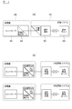
- FIG. 4A is a block diagram showing a control system of the charging system in the embodiment of the present invention
- FIG. 4B is a block diagram showing a control system of the conventional charging system.
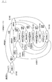
- FIG. 5 is a state transition diagram of the slave mode in the embodiment of the present invention.
- FIG. 6 is a state transition diagram of the single mode in the embodiment of the present invention.
- FIGS. 7A to 7F are diagrams showing examples of display images on the touch panel in the respective states of FIG.
- FIGS. 8A to 8F are diagrams respectively showing examples of display images on the touch panel in the respective states of FIG.
- FIG. 9 is a perspective view showing a charging system according to another embodiment.
- FIG. 10 is a circuit diagram showing a lamp I / F used in the charging system shown in FIG.
- FIG. 11 is a circuit diagram showing a control I / F used in the charging system shown in FIG.
- FIG. 1 is a diagram illustrating an overall configuration of a charging system according to the present embodiment
- FIG. 2 is a perspective view of a charger and a charging terminal according to the present embodiment
- FIG. 3 is a perspective view of another example of the charger and the charging terminal according to the present embodiment.
- 4A is a block diagram showing the control system of the charging system in the present embodiment
- FIG. 4B is a block diagram showing the control system of the conventional charging system
- FIG. 5 is a diagram of the slave mode in the present embodiment.
- State transition diagram FIG. 6 is a state transition diagram of the single mode in this embodiment.
- the charging system 1 is a system that charges a traveling battery (not shown) of the vehicle 50 and charges a fee according to the amount of charging power. System) and a charger 40.
- the vehicle 50 in the present embodiment is a vehicle having a motor generator as a power source and a traveling battery that charges and discharges the motor generator.
- the vehicle 50 is an electric vehicle or a plug-in type hybrid car. Etc. can be illustrated.
- the charging system 10 includes a charging server 20 and a charging terminal 30.
- the charging system 10 monitors the state of the charger 40 by cyclic communication, and a READY command to be described later. Such a command can be instructed to the charger 40, and the charging completion condition and the upper limit value of the charger 40 can be set.
- the charging system 10 may be able to control the start / stop of charging of the charger 40.
- the billing server 20 is a server that performs billing authentication processing for charging the battery of the vehicle 50 by the charger 40.
- the billing server 20 is connected to the billing terminal 30 via a network or the like.
- one charger 40 is connected to one charging server 20.
- the present invention is not limited to this, and a plurality of chargers are connected to one charging server 20. 40 may be connected, and the charging server 20 may manage the plurality of chargers 40 in an integrated manner.
- One charging terminal 30 may correspond to a plurality of chargers 40.
- the charging terminal 30 is provided in the vicinity of the charger 40, for example, and is connected to the controller 45 of the charger 40 via a LAN or the like.
- the charging terminal 30 includes a touch panel 31 and a card reader 32 as shown in FIG.
- the touch panel 31 is an HMI (Human Machine Interface) for billing authentication.
- the card reader 32 is, for example, a non-contact card reader capable of reading and writing an IC card.
- a charging operator for example, a driver or the like
- the operation for billing authentication is performed by approaching.
- the IC card data read by the card reader 32 is transmitted to the accounting server 20 through a network or the like.
- the IC card for example, a cash card, a credit card, a prepaid IC card charged with electronic money in advance, or the like can be exemplified.
- a contact type card reader may be provided in the charging terminal 30.
- a contact type card reader a coin mech (C / M), bill validator (B / V), etc. may be provided in the billing terminal 30.
- the charger 40 is a quick charging stand that charges the traveling battery of the vehicle 50 by supplying electric power to the vehicle 50.
- the charger 40 has a built-in power converter that converts commercial AC power into DC power and boosts the DC power to a predetermined voltage.
- the DC power converted by the power converter is supplied via a charging cable 41. To the battery of the vehicle 50.
- a charging connector 42 is attached to the tip of the charging cable 41.
- a charger is connected via the charging cable 41. 40 and the battery of the vehicle 50 are electrically connected.
- a charging start button 431, a charge stop button 432, and an emergency stop button 433 are provided on the casing 43 of the charger 40.
- the charging operator presses the charging start button 431 after attaching the charging connector 42 to the power supply inlet 51, whereby charging of the battery of the vehicle 50 is started.
- the charging stop button 432 when charging is stopped after the charging of the battery is started, the charging operator presses the charging stop button 432. Further, for example, when an abnormality occurs during charging and it is desired to stop charging urgently, the charging operator presses the emergency stop button 433.
- the casing 43 of the charger 40 is provided with three lamps 434 to 436 and a touch panel 44.
- the ready lamp 434 lights up when the charger 40 is in a chargeable state (state S120 in FIGS. 5 and 6 to be described later).
- the charge lamp 435 is lit while the battery is charged by pressing the charge start button 431 (states S131 to S135 in FIGS. 5 and 6 described later).
- the alarm lamp 436 is lit or blinked when an abnormality occurs, for example, a failure occurs in the charger 40 itself.
- the touch panel 44 is an HMI between the charger 40 and the charging operator or system administrator. For example, the charging operator confirms the progress of the charging operation, or the system administrator performs maintenance of the charger 40 or the like. Used when doing.
- the card reader 32 is provided in the housing 43 of the charger 40, and the touch panel 44 of the charger 40 also serves as the touch panel 31 of the charging terminal 30. Functions may be incorporated.
- the charger 40 includes a controller 45 configured by a computer including a CPU, a ROM, a RAM, and the like.
- the controller 45 controls the charging of the vehicle 50 by executing a control program stored in the ROM.
- the controller 45 has a communication interface 46 for communicating with the charging system 10.
- the controller 45 is based on the signal from the charging system 10 input via the communication interface 46, and the two control modes ("slave mode” and "independent mode") shown in FIGS. ) Can be selected.
- “Slave mode” shown in FIG. 5 is a mode in which the charger 40 operates in accordance with a command from the charging system 10.
- the “single mode” shown in FIG. 6 is a mode in which the charger 40 operates alone.
- the “slave mode” in the present embodiment corresponds to an example of the first mode in the present invention
- the “independent mode” in the present embodiment corresponds to an example of the second mode in the present invention.
- FIGS. 7 (a) to 7 (f) and FIGS. 8 (a) to 8 (f) are diagrams showing examples of images displayed on the touch panel 44 of the charger 40 in each state of FIG. .
- the controller 45 initializes the charger 40 and “starts” on the touch panel 44 as shown in FIG.
- the “Medium” screen is displayed.
- the controller 45 waits for a predetermined time for the cyclic signal from the charging system 10 to be input via the communication interface 46.
- the cyclic signal is transmitted, for example, every 100 [msec], whereas the predetermined time that the controller 45 waits is, for example, 8 [sec].
- the predetermined time in this state S100 is not specifically limited to said value, It can set arbitrarily.
- the cyclic signal from the billing system 10 in the present embodiment corresponds to an example of the first signal in the present invention.
- the controller 45 displays a screen as shown in FIG. 7B on the touch panel 44 in a state S110 of FIG. 5 and waits for a READY command from the charging system 10.
- the state S110 in FIG. 5 in the present embodiment corresponds to an example of the first state in the present invention.
- the charging completion condition (the charging time or charging rate (SOC: State of Charge) or the like), changing the charging time of the charging completion condition (see FIG. 7C), or changing the charging rate of the charging completion condition (see FIG. 7D). It is possible.
- the “OK” button is pressed in FIGS. 7C and 7D, the screen returns to the screen of FIG. 7B.
- the station number of each charger 40 may be set in this state S110. Good.
- the controller 45 proceeds to the state S120 in FIG.
- the READY command allows the charging operator to touch the IC card on the card reader 32 of the charging terminal 30 and then touch the inside of the frame displayed on the touch panel 24 shown in FIG.
- the controller 10 is instructed from the system 10 via the communication interface 46.
- the controller 45 receives this READY command from the charging system 10, the control right is transferred from the charging system 10 to the controller 45.
- This READY command corresponds to an example of the second signal in the present invention.
- the charger 40 can start charging the battery at any time.
- An example of the display screen of the touch panel 44 in the state S120 of FIG. 5 is shown in FIG.
- the state S120 in FIG. 5 in the present embodiment corresponds to an example of a second state in the present invention.
- the charging control in the states S131 to S135 in FIG. 5 is executed. Specifically, first, in the state S131 of FIG. 5, the controller 45 communicates with the vehicle 50 to acquire information such as the current charging rate of the traveling battery and the presence or absence of a failure.
- An example of the display screen of the touch panel 44 in the state S131 of FIG. 5 is shown in FIG.
- the controller 45 performs an insulation test by applying a voltage of, for example, about 500 [V], and further checks the failure state of the charger 40 itself in the state S133 of FIG.
- a voltage of, for example, about 500 [V] An example of the display screen of the touch panel 44 in the state S132 and the state S133 in FIG. 5 is shown in FIGS. 8B and 8C.
- the controller 45 actually supplies DC power from the charger 40 to the vehicle 50 and charges the traveling battery in the state S134 of FIG.
- An example of the display screen of the touch panel 44 in the state S134 of FIG. 5 is shown in FIG.
- the controller 45 shifts to the state S135 in FIG. 5 and stops the charging.
- An example of the display screen of the touch panel 44 in the state S135 of FIG. 5 is shown in FIG.
- the controller 45 transmits the charging result such as the amount of charging power to the charging system 10 via the communication interface 46, and the state of the controller 45 is again in FIG. Transition to state S110.
- the charging terminal 30 transmits the charging result transmitted from the controller 45 of the charger 40 to the charging server 20, and the charging server 20 calculates a fee based on the charging result and performs settlement processing.
- the control right is transferred from the controller 45 to the charging system 10, and the controller 45 of the charger 40 cannot start charging control again. It becomes a state.
- An example of the display screen of the touch panel 44 immediately after the transition from the state S135 to the state S110 in FIG. 5 is shown in FIG.
- the display screen of the touch panel 44 is switched from FIG. 8 (f) to FIG. 7 (a).
- state S140 in FIG. 5 An example of the display screen of the touch panel 44 in the state S140 in FIG. 5 is shown in FIG.
- This “single mode” is the same as the “slave mode” shown in FIG. 5 except that the state S110 of FIG. 5 is not provided. Therefore, in FIG. 6, the same state as in FIG. 5 is given the same reference numerals S100, S120, S131 to S135, and S140 as in FIG. Omitted.
- the charger 40 when the signal from the charging system 10 is not input to the controller 45, the charger 40 can operate independently. For example, the charging server 20 or the charging terminal 30 Even when a failure occurs, the battery of the vehicle 50 can be charged by the charger 40.
- the mode shifts from the “slave mode” to the “single mode”.
- the charging system 10 cannot give any instruction to the controller 45, and the above-mentioned In this cyclic communication, only the state of the charger 40 can be read.
- the controller 45 has two modes of “slave mode” and “independent mode”, but the present invention is not limited to this, and the controller 45 may have only “slave mode”. .
- the controller 45 of the charger 40 charges the battery for traveling unless the cyclic signal is input from the charging system 10 to the controller 45 via the communication interface 46 within a predetermined time. Control does not start.
- the controller 45 of the charger 40 waits for input of a signal (cyclic signal or READY command) from the charging system 10 via the communication interface 46 (states S100 and S110 in FIG. 5). Then, charging control of the running battery of the vehicle 50 (states S131 to S135 in FIG. 5) is started on the condition that a signal is input from the charging system 10 via the communication interface 46.
- a signal cyclic signal or READY command
- the charger 40 becomes a slave side with respect to the charging system 10, and it is not necessary to install a protocol corresponding to the charging system in the charger 40 as shown in FIG.
- the versatility for the device is improved.
- the controller 45 of the charger 40 has at least one condition that a signal is input from the charging system 10 via the communication interface 46 (that is, at least the charging system 10 via the communication interface 46).
- the charging control of the traveling battery is started on the condition that a signal is input from the charging system 10 via the communication interface 46.
- the controller 45 of the charger 40 in the present embodiment corresponds to an example of the control means in the present invention
- the communication interface 46 of the charger 40 in the present embodiment corresponds to an example of the interface in the present invention
- the charging system in the present embodiment. 10 corresponds to an example of an external device according to the present invention.
- a lamp I / F circuit as shown in FIG. 10 and a control I / F circuit as shown in FIG. 11 may be provided in the charging system (charging terminal 30 and charger 40).
- the charging terminal 30 can monitor the lighting / extinguishing state of the lamps 434 to 436 of the charger 40, or the charging terminal 30 can turn on / off the lamps 434 to 436. It has become.
- the lamp I / F circuit shown in FIG. 10 by closing the switch S 1, the conduction state of the contact J 2 and the contact J 3, the lamp PL (above the lamps 434 to 436 of the charger 40
- the charging terminal 30 can acquire a corresponding ON / OFF state.
- the charging terminal 30 can start charging the charger 40, or the charging terminal 30 can detect the depression of the charging start button 431.
- the switch S 2 is, for example, in conjunction with a relay provided in the coin insertion slot of the coin mech 33.
- the external device connected to the controller of the charger is not particularly limited thereto.
- a remote control device for remotely turning on / off a heater provided in the charger may be connected to the controller of the charger via a communication interface.
Landscapes
- Engineering & Computer Science (AREA)
- Power Engineering (AREA)
- Transportation (AREA)
- Mechanical Engineering (AREA)
- Life Sciences & Earth Sciences (AREA)
- Sustainable Development (AREA)
- Sustainable Energy (AREA)
- Physics & Mathematics (AREA)
- General Physics & Mathematics (AREA)
- Charge And Discharge Circuits For Batteries Or The Like (AREA)
- Secondary Cells (AREA)
- Electric Propulsion And Braking For Vehicles (AREA)
Abstract
バッテリを充電する充電器40は、バッテリへの充電を制御するコントローラ45と、コントローラ45と課金システム10との間に介在する通信インタフェース46と、を備えており、コントローラ45は、通信インタフェース46を介した課金システム10からの信号の入力を待ち、通信インタフェース46を介して課金システム10から信号が入力されたことを条件として、バッテリの充電制御を開始する。
Description
本発明は、バッテリを充電する充電器及び充電器の制御方法に関するものである。
本出願は、2011年10月7日に出願された日本国特許出願の特願2011―222666に基づく優先権を主張するものであり、文献の参照による組み込みが認められる指定国については、上記の出願に記載された内容を参照により本出願に組み込み、本出願の記載の一部とする。
本出願は、2011年10月7日に出願された日本国特許出願の特願2011―222666に基づく優先権を主張するものであり、文献の参照による組み込みが認められる指定国については、上記の出願に記載された内容を参照により本出願に組み込み、本出願の記載の一部とする。
バッテリの充電が終了したら、充電スタンドから管理センタサーバに充電電力量情報を送信し、管理センタサーバで充電電力に応じて充電料金の課金を行う技術が知られている(例えば特許文献1(段落0066及び図4)参照)。
上記の技術では、充電スタンド側から管理センタサーバに対して情報を能動的に送信するため、充電スタンドがマスタ側となっている。そのため、管理センタサーバが複数種存在する場合には、それぞれの管理センタサーバに対応したプロトコルを充電スタンドに個別に実装する必要があり、管理センタサーバ等の外部装置に対する充電スタンドの汎用性に劣るという問題があった。
本発明が解決しようとする課題は、外部装置に対する汎用性に優れた充電器および充電器の制御方法を提供することである。
本発明は、制御手段が、インタフェースを介して外部装置からの信号の入力を待ち、インタフェースを介して外部装置から信号が入力されたことを条件として、バッテリの充電制御を開始することによって上記課題を解決する。
本発明によれば、外部装置に対して充電器がスレーブ側となり、それぞれの外部装置に対応したプロトコルを充電器に実装する必要がなくなるので、外部装置に対する充電器の汎用性が向上する。
以下、本発明の実施形態を図面に基づいて説明する。
図1は本実施形態における充電システムの全体構成を示す図、図2は本実施形態における充電器及び課金端末の斜視図、図3は本実施形態における充電器及び課金端末の他の例の斜視図、図4(a)は本実施形態における充電システムの制御系を示すブロック図、図4(b)は従来の充電システムの制御系を示すブロック図、図5は本実施形態におけるスレーブモードの状態遷移図、図6は本実施形態における単独モードの状態遷移図である。
本実施形態における充電システム1は、図1に示すように、車両50の走行用バッテリ(不図示)を充電し、その充電電力量に応じた料金を課金するシステムであり、課金システム10(上位システム)と、充電器40と、を備えている。
なお、本実施形態における車両50は、動力源としてのモータジェネレータと、当該モータジェネレータに対して充放電を行う走行用バッテリと、を有する車両であり、例えば、電気自動車やプラグインタイプのハイブリッドカー等を例示することができる。
課金システム10は、課金サーバ20と、課金端末30と、を備えており、本実施形態では、料金の課金に加えて、サイクリック通信によって充電器40の状態をモニタリングしたり、後述するREADYコマンド等の指令を充電器40に指示したり、充電器40の充電完了条件やその上限値を設定することが可能となっている。なお、課金システム10が、充電器40の充電開始/停止を制御可能であってもよい。
課金サーバ20は、充電器40による車両50のバッテリへの充電に対して課金認証処理を行うサーバである。この課金サーバ20は、ネットワーク等を介して課金端末30に接続されている。
なお、図1では、1台の課金サーバ20に対して、1台の充電器40が接続されているが、特にこれに限定されず、1台の課金サーバ20に対して、複数の充電器40を接続して、当該課金サーバ20で複数の充電器40を統括的に管理してもよい。また、1台の課金端末30で複数の充電器40に対応してもよい。
課金端末30は、例えば充電器40の近傍に設けられており、LAN等を介して、充電器40のコントローラ45に接続されている。この課金端末30は、図2に示すように、タッチパネル31と、カードリーダ32と、を備えている。タッチパネル31は、課金認証のためのHMI(Human Machine Interface)である。また、カードリーダ32は、例えば、ICカードを読み書き可能な非接触式のカードリーダである。
例えば、充電操作を行う充電操作者(例えばドライバ等)は、車両50のバッテリの充電に際して、タッチパネル31に表示される案内に従って、当該タッチパネル31上のボタンにタッチしたり、ICカードをカードリーダ32に近づけることで、課金認証のための操作を行う。カードリーダ32が読み取ったICカードのデータは、ネットワーク等を通じて課金サーバ20に送信される。ICカードの具体例としては、例えば、キャッシュカード、クレジットカード、或いは、電子マネーが予めチャージされたプリペイド型のICカード等を例示することができる。
なお、非接触式のカードリーダ32に代えて、接触式のカードリーダを課金端末30に設けてもよいし、非接触式のカードリーダ32に加えて、接触式のカードリーダ、コインメック(C/M)、ビルバリ(B/V)等を課金端末30に設けてもよい。
充電器40は、車両50に電力を供給することで、車両50の走行用バッテリを充電する急速充電スタンドである。この充電器40は、商用交流電力を直流電力に変換し、これを所定の電圧に昇圧する電力変換器が内蔵されており、この電力変換器で変換された直流電力を、充電ケーブル41を介して車両50のバッテリに供給する。
図1に示すように、この充電ケーブル41の先端には充電コネクタ42が取り付けられており、当該充電コネクタ42を、車両50の給電インレット51に装着することで、充電ケーブル41を介して充電器40と車両50のバッテリとが電気的に接続される。
図2に示すように、この充電器40の筐体43には、充電開始ボタン431と、充電停止ボタン432と、緊急停止ボタン433と、が設けられている。充電操作者が、充電コネクタ42を給電インレット51に装着した後に、充電開始ボタン431を押すことで、車両50のバッテリの充電が開始される。一方、バッテリの充電を開始してから当該充電を停止させる場合には、充電操作者は充電停止ボタン432を押す。また、例えば充電中に異常が発生して充電を緊急停止させたい場合には、充電操作者は緊急停止ボタン433を押す。
また、充電器40の筐体43には、3つのランプ434~436と、タッチパネル44と、が設けられている。
レディランプ434は、充電器40が充電可能な状態(後述する図5や図6の状態S120)になった場合に点灯する。チャージランプ435は、充電開始ボタン431が押されてバッテリが充電されている間中(後述する図5や図6の状態S131~S135)、点灯する。アラームランプ436は、例えば充電器40自体に故障が発生する等の異常が発生した場合に点灯或いは点滅する。
タッチパネル44は、充電器40と充電操作者やシステム管理者との間のHMIであり、例えば、充電操作者が充電作業の進捗状態を確認したり、システム管理者が充電器40のメンテナンス等を行う際に使用される。
なお、図3に示すように、充電器40の筐体43にカードリーダ32を設けると共に、充電器40のタッチパネル44が課金端末30のタッチパネル31を兼ねることで、充電器40に課金端末30の機能を組み込んでもよい。
さらに、この充電器40は、CPU、ROM、RAM等を備えたコンピュータから構成されたコントローラ45を備えている。このコントローラ45は、ROMに記憶された制御プログラムを実行することで、車両50の充電の制御を行う。このコントローラ45は、図4(a)に示すように、課金システム10と通信を行うための通信インタフェース46を有している。
本実施形態では、このコントローラ45は、通信インタフェース46を介して入力される課金システム10からの信号に基づいて、図5及び図6に示す2つの制御モード(「スレーブモード」と「単独モード」)のいずれか一方を選択することが可能となっている。
図5に示す「スレーブモード」は、充電器40が課金システム10からの指令に従って動作するモードである。一方、図6に示す「単独モード」は、充電器40が単独で動作するモードである。本実施形態における「スレーブモード」が本発明における第1のモードの一例に相当し、本実施形態における「単独モード」が本発明における第2のモードの一例に相当する。
以下に、「スレーブモード」でのコントローラ45による制御の流れについて、図7(a)~図7(f)及び図8(a)~図8(f)を参照しながら説明する。図7(a)~図7(f)及び図8(a)~図8(f)は図5の各状態において、充電器40のタッチパネル44上に表示される画像の一例を示す図である。
先ず、充電器40の電源が投入されると、図5の状態S100において、コントローラ45は、充電器40の初期化を行うと共に、図7(a)に示すように、タッチパネル44上に「起動中」の画面を表示する。
この状態S100において、コントローラ45は、課金システム10からのサイクリック信号が通信インタフェース46を介して入力されるのを所定時間待つ。このサイクリック信号は、例えば100[msec]毎に発信されるのに対し、コントローラ45が待機する前記所定時間は、例えば8[sec]である。なお、この状態S100における所定時間は、上記の値に特に限定されず、任意に設定することができる。本実施形態における課金システム10からのサイクリック信号が、本発明における第1の信号の一例に相当する。
この状態S100において、コントローラ45は、所定時間内に、通信インタフェース46を介して課金システム10からのサイクリック信号を受信した場合には、図5に示す「スレーブモード」を選択する。これに対し、コントローラ45は、所定時間を経過しても課金システム10からサイクリック信号を受信しなかった場合には、図6に示す「単独モード」を選択する。なお、課金システム10と充電器40との間でサイクリック通信が確立されると、課金システム10はこのサイクリック通信によって充電器40の状態を読み取ることができる。コントローラ45によって「スレーブモード」が実行されている間、このサイクリック通信は維持される。
「スレーブモード」が選択されたら、コントローラ45は、図5の状態S110において、図7(b)に示すような画面をタッチパネル44上に表示して、課金システム10からのREADYコマンドを待つ。本実施形態における図5の状態S110が、本発明における第1の状態の一例に相当する。
この図5の状態S110では、課金システム10側に制御権があるため、充電器40のコントローラ45は、課金システム10からREADYコマンドを受け取るまで、走行用バッテリの充電制御を開始することができない。この状態S110では、例えば、管理者が、タッチパネル44を介して、充電器40の管理やメンテナンスを行うことが可能となっている。
具体的には、管理者が、図7(b)に示すタッチパネル上の「管理」ボタンや「メンテナンス」ボタンにタッチすると、充電完了条件(充電作業が完了する充電時間や充電率(SOC:State of Charge)等)を選択したり、充電完了条件の充電時間を変更したり(図7(c)参照)、或いは、充電完了条件の充電率を変更する(図7(d)参照)ことが可能となっている。なお、図7(c)や図7(d)において「OK」ボタンを押すと、図7(b)の画面に戻る。また、特に図示しないが、1台の課金サーバ20や1台の課金端末30で複数の充電器40に対応する場合には、この状態S110において、それぞれの充電器40の局番を設定してもよい。
本実施形態では、充電器40のコントローラ45が充電制御を開始することができない状態S110を設けることで、「スレーブモード」において、ICカードの認証が完了していなかったり、充電完了条件等を設定しているにも関わらず、勝手に充電器40の充電開始ボタン431が押されて充電処理が開始してしまうのを防止することが可能となっている。
図5の状態S110において、通信インタフェース46を介して課金システム10からコントローラ45にREADYコマンドが入力されたら、コントローラ45は、図5の状態S120に移行する。このREADYコマンドは、例えば、充電操作者が、課金端末30のカードリーダ32にICカードをタッチさせた後に、図7(b)に示すタッチパネル24に表示された枠内をタッチすることで、課金システム10から通信インタフェース46を介してコントローラ45に指示される。コントローラ45がこのREADYコマンドを課金システム10から受信することで、制御権が課金システム10からコントローラ45に移る。このREADYコマンドが、本発明における第2の信号の一例に相当する。
この図5の状態S120では、制御権がコントローラ45にあるため、充電操作者が充電開始ボタン431を押せば、充電器40がバッテリの充電をいつでも開始可能な状態となっている。この図5の状態S120におけるタッチパネル44の表示画面の一例を図7(e)に示す。本実施形態における図5の状態S120が、本発明における第2の状態の一例に相当する。
そして、充電操作者が充電器40の充電開始ボタン431を押すと、図5の状態S131~S135における充電制御が実行される。具体的には、先ず、図5の状態S131において、コントローラ45は、車両50と通信を行うことで、走行用バッテリの現状の充電率や故障の有無等の情報を取得する。この図5の状態S131におけるタッチパネル44の表示画面の一例を図8(a)に示す。
次いで、図5の状態S132において、コントローラ45は、例えば500[V]程度の電圧を印加して絶縁試験を行い、さらに、図5の状態S133において、充電器40自身の故障状態を確認する。この図5の状態S132及び状態S133におけるタッチパネル44の表示画面の一例を図8(b)及び図8(c)に示す。
そして、充電開始条件が成立したら、コントローラ45は、図5の状態S134において、実際に充電器40から直流電力を車両50に供給して走行用バッテリを充電する。この図5の状態S134におけるタッチパネル44の表示画面の一例を図8(d)に示す。
図5の状態S134で車両50のバッテリの充電を行って充電完了条件が成立したら、コントローラ45は、図5の状態S135に移行して充電を停止させる。この図5の状態S135におけるタッチパネル44の表示画面の一例を図8(e)に示す。
なお、図5の状態S131~S134において、例えば充電操作者が充電停止ボタン432を押す等して充電停止イベントが発生した場合にも、この図5の状態S135に移行する。
そして、図5の状態S135において充電の停止作業が完了したら、コントローラ45は、通信インタフェース46を介して、充電電力量等の充電結果を課金システム10に送信し、コントローラ45の状態は再び図5の状態S110に移行する。
課金端末30は、充電器40のコントローラ45から送信された充電結果を課金サーバ20に送信し、課金サーバ20は、この充電結果に基づいて料金を算出して決済処理する。
本実施形態では、課金システム10が充電器40のコントローラ45から充電結果を受け取ると、制御権がコントローラ45から課金システム10に移り、再び充電器40のコントローラ45は充電制御を開始することができない状態となる。図5における状態S135から状態S110に移行した直後のタッチパネル44の表示画面の一例を、図8(f)に示す。なお、一定時間が経過したら、タッチパネル44の表示画面は、図8(f)から図7(a)に切り替わる。
なお、図5のいずれかの状態S100,S110,S120,S131~S135において、充電器40が故障した場合には、図5の状態S140に移行して、充電操作者に故障発生を喚起する。この図5の状態S140におけるタッチパネル44の表示画面の一例を図7(f)に示す。
一方、図5の状態S100において、充電器40のコントローラ45が、所定時間内に、通信インタフェース46を介して課金システム10からのサイクリック信号を受信しない場合には、図6に示す「単独モード」に移行する。
この「単独モード」は、図5の状態S110を有していない点を除いて、上述の図5に示す「スレーブモード」と同一である。そのため、図6中において、図5と同じ状態に対して、図5と同一の符号S100,S120,S131~S135,及びS140を付して、図6の「単独モード」についての詳細な説明は省略する。
この「単独モード」では、課金システム10からのREADYコマンドを待つ状態S110がないため、「単独モード」が選択されると、図6において状態S100から状態S120に移行し、充電器40のコントローラ45は、課金システム10からの指示なく、車両50のバッテリの充電制御を開始することが可能となっている。
このように、本実施形態では、課金システム10からの信号がコントローラ45に入力されない場合に、充電器40は単独で動作することが可能となっているので、例えば課金サーバ20や課金端末30が故障した場合でも、充電器40によって車両50のバッテリを充電することが可能となっている。
さらに、本実施形態では、コントローラ45が「単独モード」を実行している間に、通信インタフェース46を介して課金システム10からサイクリック信号が入力された場合には、「単独モード」から「スレーブモード」に移行する。
同様に、本実施形態では、コントローラ45が「スレーブモード」を実行している間に、課金システム10からのサイクリック信号が途絶えた場合には、「スレーブモード」から「単独モード」に移行する。
このため、「単独モード」で使用されていた充電器40を途中から「スレーブモード」に自動的に切り替えたり、「スレーブモード」を選択した後に課金サーバ20や課金端末30が故障した場合でも「単独モード」に自動的に移行することが可能となっている。
但し、本実施形態では、充電器40のコントローラ45が充電制御状態(図5における状態S131~S135)にある間は、課金システム10はコントローラ45に対して一切指示をすることができず、上述のサイクリック通信によって、充電器40の状態を読み取ることしかできない。
そのため、「単独モード」においてコントローラ45が充電制御状態にある間に、課金システム10からサイクリック信号が入力された場合には、この充電制御状態が完了した後(すなわち状態S135を完了した後)に、「スレーブモード」(図5)における状態S110に移行する。
同様に、「スレーブモード」においてコントローラ45が充電制御状態にある間に、課金システム10からのサイクリック信号が途絶えた場合には、この充電制御状態が完了した後(すなわち状態S135を完了した後)に、「単独モード」(図6)に移行する。但し、この場合には、「単独モード」の状態S120に移行する。この「単独モード」における状態S120が、本発明における第3の状態の一例に相当する。
なお、本実施形態では、コントローラ45が「スレーブモード」と「単独モード」の2つのモードを備えていているが、特にこれに限定されず、コントローラ45が「スレーブモード」のみを備えてもよい。この場合には、図5の状態S100において、所定時間内に、通信インタフェース46を介して課金システム10からサイクリック信号がコントローラ45に入力されない限り、充電器40のコントローラ45が走行用バッテリの充電制御を開始することはない。
ところで、従来のように、充電器が外部システムに対してマスタ側となっている場合には、それぞれ課金システムに対応したプロトコルを充電器に実装しなければならない。具体的には、図4(b)に示すように、例えば、A社の課金システムに対応する場合には、A社専用のゲートウェイを充電器に設けなければならず、B社の課金システムに対応する場合にはB社専用のゲートウェイを充電器に設けなければならず、充電器の汎用性が劣っている。
これに対し、本実施形態では、充電器40のコントローラ45が、通信インタフェース46を介して課金システム10からの信号(サイクリック信号やREADYコマンド)の入力を待ち(図5の状態S100やS110)、通信インタフェース46を介して課金システム10から信号が入力されたことを一つの条件として、車両50の走行用バッテリの充電制御(図5の状態S131~S135)を開始する。
このため、課金システム10に対して充電器40がスレーブ側となり、図4(a)に示すように、課金システムに対応したプロトコルを充電器40に実装する必要がなくなるので、課金サーバ等の外部装置に対する汎用性が向上する。
なお、充電開始のコマンドも通信インタフェース46を介して課金システム10からコントローラ45に入力される場合には、走行用バッテリの充電制御を開始する条件は、図5においては、通信インタフェース46を介した課金システム10からの信号(サイクリック信号、READYコマンド、充電開始コマンド)の入力のみとなる。
従って、本実施形態では、充電器40のコントローラ45が、通信インタフェース46を介して課金システム10から信号が入力されたことを少なくとも一つの条件として(すなわち、少なくとも通信インタフェース46を介して課金システム10から信号が入力されたことを条件として)、走行用バッテリの充電制御を開始する。
本実施形態における充電器40のコントローラ45が本発明における制御手段の一例に相当し、本実施形態における充電器40の通信インタフェース46が本発明におけるインタフェースの一例に相当し、本実施形態における課金システム10が本発明における外部装置の一例に相当する。
なお、図9に示すように、課金端末30をコインメック33やビルバリ34だけで構成した場合には、課金サーバ20との接続は不要となる。この場合には、図10に示すようなランプI/F回路と、図11に示すような制御I/F回路と、を充電システム(課金端末30及び充電器40)に設けてもよい。
図10に示すランプI/F回路では、課金端末30が充電器40のランプ434~436の点灯/消灯状態を監視したり、課金端末30が当該ランプ434~436を点灯/消灯させることが可能となっている。
具体的には、図10に示すランプI/F回路では、スイッチS1を閉じて、接点J2と接点J3との導通状態によって、充電器40のランプPL(上述のランプ434~436に相当)の点灯/消灯状態を、課金端末30が取得することができる。
また、スイッチS1を閉じて、接点J1と接点J5とを短絡させることで、課金端末30と充電器40の両方が、ランプPLを点灯/消灯させることができる。
これに対し、スイッチS1を開いて、接点J2と接点J3との導通状態によって、充電器40のランプPLの点灯/消灯状態を課金端末30が取得することができ、接点J1と接点J5を短絡させることで、充電器40側の制御をブロックしつつ、課金端末30がランプPLを点灯/消灯させることができる。
一方、図11に示す制御I/F回路では、課金端末30が充電器40の充電を開始させたり、課金端末30が充電開始ボタン431の押し下げを検出することが可能となっている。
具体的には、図11に示す制御I/F回路では、接点J6と接点J8を短絡させることで、課金端末30によって車両50のバッテリの充電を開始させることができる。
また、スイッチS2を閉じて、接点J7と接点J8の導通状態によって、充電器40の充電開始ボタン431の押し下げを検出することができる。なお、スイッチS2は、例えば、コインメック33のコイン投入部に設けられたリレーと連動している。
なお、以上に説明した実施形態は、本発明の理解を容易にするために記載されたものであって、本発明を限定するために記載されたものではない。したがって、上記の実施形態に開示された各要素は、本発明の技術的範囲に属する全ての設計変更や均等物をも含む趣旨である。
例えば、上述の実施形態では、充電器40のコントローラ45に課金システム10を接続した例について説明したが、充電器のコントローラに接続される外部装置は特にこれに限定されない。例えば、充電器内に設けられたヒータを遠隔でオン/オフする操作する遠隔操作装置を、通信インタフェースを介して充電器のコントローラに接続してもよい。
1…充電システム
10…課金システム
20…課金サーバ
30…課金端末
31…タッチパネル
32…カードリーダ
33…コインメック
34…ビルバリ
40…充電器
41…充電ケーブル
42…充電コネクタ
43…筐体
431…充電開始ボタン
432…充電停止ボタン
433…緊急停止ボタン
434…レディランプ
435…チャージランプ
436…アラームランプ
44…タッチパネル
45…コントローラ
46…通信インタフェース
50…車両
51…給電インレット
10…課金システム
20…課金サーバ
30…課金端末
31…タッチパネル
32…カードリーダ
33…コインメック
34…ビルバリ
40…充電器
41…充電ケーブル
42…充電コネクタ
43…筐体
431…充電開始ボタン
432…充電停止ボタン
433…緊急停止ボタン
434…レディランプ
435…チャージランプ
436…アラームランプ
44…タッチパネル
45…コントローラ
46…通信インタフェース
50…車両
51…給電インレット
Claims (9)
- バッテリを充電する充電器であって、
前記バッテリへの充電の制御を行う制御手段と、
前記制御手段と外部装置との間に介在するインタフェースと、を備えており、
前記制御手段は、前記インタフェースを介した前記外部装置からの信号の入力を待ち、前記インタフェースを介して前記外部装置から信号が入力されたことを条件として、前記バッテリの充電制御を開始することを特徴とする充電器。 - 請求項1に記載の充電器であって、
前記制御手段は、
前記充電器が前記外部装置からの信号に従う第1のモード、又は、
前記充電器が単独で動作する第2のモード、
のいずれか一方を、前記インタフェースを介して入力される前記外部装置からの信号に基づいて選択することを特徴とする充電器。 - 請求項2に記載の充電器であって、
前記制御手段は、
所定時間内に、前記インタフェースを介して前記外部装置から信号が入力された場合に、前記第1のモードを選択し、
前記所定時間内に、前記インタフェースを介して前記外部装置から信号が入力されない場合に、前記第2のモードを選択することを特徴とする充電器。 - 請求項3に記載の充電器であって、
前記制御手段は、
前記インタフェースを介して前記外部装置から第1の信号が入力された場合に、前記第1のモードにおいて前記外部装置からの第2の信号を待つ第1の状態に移行し、
前記インタフェースを介して前記外部装置から前記第2の信号が入力された場合に、前記第1のモードにおいて前記バッテリの充電を開始可能な第2の状態に移行することを特徴とする充電器。 - 請求項3又は4に記載の充電器であって、
前記制御手段は、前記所定時間内に、前記インタフェースを介して前記外部装置から信号が入力されない場合には、前記第2のモードにおいて前記バッテリの充電を開始可能な第3の状態に移行することを特徴とする充電器。 - 請求項2~5の何れかに記載の充電器であって、
前記制御手段は、前記第2のモードにおいて前記インタフェースを介して前記外部装置から信号が入力された場合には、前記第2のモードから前記第1のモードに移行することを特徴とする充電器。 - 請求項6に記載の充電器であって、
前記制御手段は、前記バッテリの充電が終了した後に、前記第2のモードから前記第1のモードに移行することを特徴とする充電器。 - 請求項1~7の何れかに記載の充電器であって、
前記制御手段は、前記インタフェースを介して入力される前記外部装置からの信号が途絶えた場合に、前記第1のモードから前記第2のモードに移行することを特徴とする充電器。 - バッテリを充電する充電器の制御方法であって、
前記充電器のインタフェースを介した外部装置からの信号の入力を待ち、前記インタフェースを介して前記外部装置から前記充電器の制御手段に信号が入力されたことを条件として、前記バッテリの充電制御を開始することを特徴とする充電器の制御方法。
Priority Applications (3)
| Application Number | Priority Date | Filing Date | Title |
|---|---|---|---|
| US14/349,440 US9376030B2 (en) | 2011-10-07 | 2012-09-28 | Charger and method of controlling charger |
| CN201280049212.8A CN103843224B (zh) | 2011-10-07 | 2012-09-28 | 充电器及充电器的控制方法 |
| EP12837939.3A EP2765676B1 (en) | 2011-10-07 | 2012-09-28 | Charger and method for controlling charger |
Applications Claiming Priority (2)
| Application Number | Priority Date | Filing Date | Title |
|---|---|---|---|
| JP2011-222666 | 2011-10-07 | ||
| JP2011222666A JP5459286B2 (ja) | 2011-10-07 | 2011-10-07 | 充電システム及び充電システムの制御方法 |
Publications (1)
| Publication Number | Publication Date |
|---|---|
| WO2013051482A1 true WO2013051482A1 (ja) | 2013-04-11 |
Family
ID=48043642
Family Applications (1)
| Application Number | Title | Priority Date | Filing Date |
|---|---|---|---|
| PCT/JP2012/075158 Ceased WO2013051482A1 (ja) | 2011-10-07 | 2012-09-28 | 充電器及び充電器の制御方法 |
Country Status (5)
| Country | Link |
|---|---|
| US (1) | US9376030B2 (ja) |
| EP (1) | EP2765676B1 (ja) |
| JP (1) | JP5459286B2 (ja) |
| CN (1) | CN103843224B (ja) |
| WO (1) | WO2013051482A1 (ja) |
Families Citing this family (12)
| Publication number | Priority date | Publication date | Assignee | Title |
|---|---|---|---|---|
| JP2014241670A (ja) * | 2013-06-11 | 2014-12-25 | シャープ株式会社 | 充電・給電システム |
| JP6146179B2 (ja) * | 2013-07-17 | 2017-06-14 | 日産自動車株式会社 | 充電装置及び充電装置の制御方法 |
| US9490644B2 (en) * | 2013-09-09 | 2016-11-08 | Apple Inc. | Reconfigurable compensator with large-signal stabilizing network |
| US10946760B2 (en) * | 2017-08-29 | 2021-03-16 | Enel X North America, Inc. | Remote indicator of state of charging of electric vehicle |
| KR102536218B1 (ko) * | 2017-12-28 | 2023-05-25 | 현대자동차주식회사 | 충전 장치, 충전 관리 서버 및 충전 방법 |
| CN108973740A (zh) * | 2018-08-01 | 2018-12-11 | 佛山市甜慕链客科技有限公司 | 一种充电站、充电接口及充电方法 |
| US11989070B2 (en) * | 2020-01-23 | 2024-05-21 | Panasonic Intellectual Property Management Co., Ltd. | Energy storage pack authentication method, energy storage pack, charging device, electric mobile object, and control device for electric mobile object |
| US12189751B2 (en) * | 2020-01-23 | 2025-01-07 | Panasonic Intellectual Property Management Co., Ltd. | Power storage pack authentication method, power storage pack, charging device, electric mobile body, and electric mobile body control device |
| CN114138382B (zh) * | 2020-09-03 | 2024-10-11 | 比亚迪股份有限公司 | 充电柜交互界面的切换方法、装置、电子设备及介质 |
| JP7509105B2 (ja) | 2021-09-22 | 2024-07-02 | トヨタ自動車株式会社 | 車両および充電システム |
| CN114523882B (zh) * | 2022-03-21 | 2023-12-19 | 苏州赤兔驱动科技有限公司 | 一种多元式高精度锂电池预热系统 |
| KR20250093616A (ko) * | 2022-10-27 | 2025-06-24 | 크라운 이큅먼트 코포레이션 | 차량용 배터리 시스템과 배터리 충전기 연결에 대한 디스플레이 스크린 알림 |
Citations (10)
| Publication number | Priority date | Publication date | Assignee | Title |
|---|---|---|---|---|
| JPH0937479A (ja) * | 1995-07-17 | 1997-02-07 | Canon Inc | 情報処理装置 |
| JP2004222457A (ja) * | 2003-01-16 | 2004-08-05 | Sony Corp | 充電システム、携帯電子機器、充電装置及び充電方法、中央管理装置及び中央管理方法 |
| JP2006333648A (ja) * | 2005-05-27 | 2006-12-07 | Ricoh Co Ltd | キャパシタ電源装置,加熱装置,画像形成装置および複写装置 |
| JP2007107998A (ja) * | 2005-10-13 | 2007-04-26 | Kansai Electric Power Co Inc:The | 蓄電池放電特性測定装置 |
| JP2007252175A (ja) * | 2006-02-16 | 2007-09-27 | Matsushita Electric Ind Co Ltd | 蓄電装置 |
| JP2008086192A (ja) * | 2006-08-31 | 2008-04-10 | Semiconductor Energy Lab Co Ltd | 蓄電装置及び当該蓄電装置を具備する半導体装置 |
| JP2010110068A (ja) * | 2008-10-29 | 2010-05-13 | Fujitsu Ten Ltd | 制御装置 |
| JP2010114988A (ja) | 2008-11-05 | 2010-05-20 | Denso Corp | 車両用充電装置および車両用充電システム |
| JP2011023271A (ja) * | 2009-07-17 | 2011-02-03 | Yanagi Elec Co Ltd | 組電池の電池容量制御装置 |
| WO2011086695A1 (ja) * | 2010-01-18 | 2011-07-21 | トヨタ自動車株式会社 | 車両 |
Family Cites Families (14)
| Publication number | Priority date | Publication date | Assignee | Title |
|---|---|---|---|---|
| JPH08161178A (ja) * | 1994-12-09 | 1996-06-21 | Chinon Ind Inc | コンピュータ周辺装置 |
| JP2002074477A (ja) * | 2000-08-31 | 2002-03-15 | Matsushita Refrig Co Ltd | 自動販売機 |
| JP2006127434A (ja) * | 2004-10-26 | 2006-05-18 | Masao Ishizu | 充電機能付自動販売機 |
| US7764046B2 (en) | 2006-08-31 | 2010-07-27 | Semiconductor Energy Laboratory Co., Ltd. | Power storage device and semiconductor device provided with the power storage device |
| CN201163427Y (zh) * | 2008-01-31 | 2008-12-10 | 浙江省电力公司 | 充电站充电计费系统 |
| JP5240765B2 (ja) * | 2008-07-09 | 2013-07-17 | トヨタ自動車株式会社 | 駐車システム |
| EP2454639A1 (en) | 2009-07-17 | 2012-05-23 | Gridpoint, Inc. | System and methods for smart charging techniques, values and guarantees |
| US20110016063A1 (en) | 2009-07-17 | 2011-01-20 | Gridpoint, Inc. | System and methods for smart charging techniques |
| US8350525B2 (en) * | 2009-08-05 | 2013-01-08 | Credit Lock, Llc | Charging vehicles in a parking area |
| JP5106508B2 (ja) * | 2009-10-09 | 2012-12-26 | 中国電力株式会社 | 充電スタンド案内システム、制御サーバ及びスタンドサーバ |
| JP5568772B2 (ja) * | 2009-11-10 | 2014-08-13 | 昭和シェル石油株式会社 | 退出誘導機能を有する車載バッテリ充電システム |
| JP5788636B2 (ja) * | 2009-12-16 | 2015-10-07 | ソニー株式会社 | 電動移動体、管理装置、駆動管理方法、及び充電装置 |
| US9043038B2 (en) * | 2010-02-18 | 2015-05-26 | University Of Delaware | Aggregation server for grid-integrated vehicles |
| JP5582824B2 (ja) * | 2010-03-02 | 2014-09-03 | 株式会社日立システムズ | 駐車場用電気自動車充電システム及び駐車場用電気自動車充電方法 |
-
2011
- 2011-10-07 JP JP2011222666A patent/JP5459286B2/ja not_active Expired - Fee Related
-
2012
- 2012-09-28 WO PCT/JP2012/075158 patent/WO2013051482A1/ja not_active Ceased
- 2012-09-28 CN CN201280049212.8A patent/CN103843224B/zh not_active Expired - Fee Related
- 2012-09-28 EP EP12837939.3A patent/EP2765676B1/en not_active Not-in-force
- 2012-09-28 US US14/349,440 patent/US9376030B2/en active Active
Patent Citations (10)
| Publication number | Priority date | Publication date | Assignee | Title |
|---|---|---|---|---|
| JPH0937479A (ja) * | 1995-07-17 | 1997-02-07 | Canon Inc | 情報処理装置 |
| JP2004222457A (ja) * | 2003-01-16 | 2004-08-05 | Sony Corp | 充電システム、携帯電子機器、充電装置及び充電方法、中央管理装置及び中央管理方法 |
| JP2006333648A (ja) * | 2005-05-27 | 2006-12-07 | Ricoh Co Ltd | キャパシタ電源装置,加熱装置,画像形成装置および複写装置 |
| JP2007107998A (ja) * | 2005-10-13 | 2007-04-26 | Kansai Electric Power Co Inc:The | 蓄電池放電特性測定装置 |
| JP2007252175A (ja) * | 2006-02-16 | 2007-09-27 | Matsushita Electric Ind Co Ltd | 蓄電装置 |
| JP2008086192A (ja) * | 2006-08-31 | 2008-04-10 | Semiconductor Energy Lab Co Ltd | 蓄電装置及び当該蓄電装置を具備する半導体装置 |
| JP2010110068A (ja) * | 2008-10-29 | 2010-05-13 | Fujitsu Ten Ltd | 制御装置 |
| JP2010114988A (ja) | 2008-11-05 | 2010-05-20 | Denso Corp | 車両用充電装置および車両用充電システム |
| JP2011023271A (ja) * | 2009-07-17 | 2011-02-03 | Yanagi Elec Co Ltd | 組電池の電池容量制御装置 |
| WO2011086695A1 (ja) * | 2010-01-18 | 2011-07-21 | トヨタ自動車株式会社 | 車両 |
Non-Patent Citations (1)
| Title |
|---|
| See also references of EP2765676A4 |
Also Published As
| Publication number | Publication date |
|---|---|
| EP2765676B1 (en) | 2020-12-09 |
| CN103843224A (zh) | 2014-06-04 |
| US20140232327A1 (en) | 2014-08-21 |
| CN103843224B (zh) | 2016-11-09 |
| US9376030B2 (en) | 2016-06-28 |
| EP2765676A1 (en) | 2014-08-13 |
| JP5459286B2 (ja) | 2014-04-02 |
| JP2013085346A (ja) | 2013-05-09 |
| EP2765676A4 (en) | 2015-12-16 |
Similar Documents
| Publication | Publication Date | Title |
|---|---|---|
| JP5459286B2 (ja) | 充電システム及び充電システムの制御方法 | |
| JP4591823B2 (ja) | 電力供給システム | |
| KR101245540B1 (ko) | 주위 전기 자동차를 이용해 방전된 전기 자동차에게 충전서비스를 제공하는 과금 가능 휴대형 장치 | |
| JP2009296824A (ja) | 充電システム | |
| US20130110340A1 (en) | Electric vehicle, charging stand, and method for charging the electric vehicle | |
| EP2767430A1 (en) | Charging control device for vehicle, and vehicle equippped with same | |
| JP7528784B2 (ja) | 電力伝送システム | |
| EP4323224A1 (en) | Electric vehicle charging system with a charging cable that includes an inline cable controller | |
| CN105052003A (zh) | 供电装置、车辆及非接触式供电系统 | |
| CN105075055A (zh) | 非接触式供电系统 | |
| JP2010187466A (ja) | 車両用バッテリ充電装置 | |
| CN104283238A (zh) | 用于移动终端的车载无线充电系统 | |
| CN104283239A (zh) | 用于移动终端的车载无线充电系统 | |
| JP2018157719A (ja) | サーバ及び充電システム | |
| JP2012075247A (ja) | 制御プログラム、充電最適制御装置および駐車場システム | |
| CN110014889B (zh) | 对具有电驱动器的车辆的低电压车载网络的供电 | |
| EP3684084A1 (en) | Device and method for varying communication path of electric vehicle charger | |
| JP6628495B2 (ja) | 充電システム | |
| JP2016052246A (ja) | 車両充電装置及び充電方法 | |
| JP6546419B2 (ja) | 駐車管理システム | |
| CN107813711B (zh) | 充电装置以及充电装置的控制方法 | |
| JP7509105B2 (ja) | 車両および充電システム | |
| CN114274833A (zh) | 一种电池包更换的控制方法、装置、设备和介质 | |
| JP2010124556A (ja) | 給電装置および車両 | |
| KR20130136702A (ko) | 차량 배터리의 충전을 위한 통신 인터페이스 시스템 및 이를 이용한 차량 배터리의 충전방법, 차량 배터리의 충전을 위한 통신 인터페이스 시스템을 구비한 전기자동차 |
Legal Events
| Date | Code | Title | Description |
|---|---|---|---|
| 121 | Ep: the epo has been informed by wipo that ep was designated in this application |
Ref document number: 12837939 Country of ref document: EP Kind code of ref document: A1 |
|
| WWE | Wipo information: entry into national phase |
Ref document number: 14349440 Country of ref document: US |
|
| NENP | Non-entry into the national phase |
Ref country code: DE |
|
| WWE | Wipo information: entry into national phase |
Ref document number: 2012837939 Country of ref document: EP |