WO2013051616A1 - インバータ装置 - Google Patents
インバータ装置 Download PDFInfo
- Publication number
- WO2013051616A1 WO2013051616A1 PCT/JP2012/075669 JP2012075669W WO2013051616A1 WO 2013051616 A1 WO2013051616 A1 WO 2013051616A1 JP 2012075669 W JP2012075669 W JP 2012075669W WO 2013051616 A1 WO2013051616 A1 WO 2013051616A1
- Authority
- WO
- WIPO (PCT)
- Prior art keywords
- current
- axis
- axis current
- inverter
- calculated
- Prior art date
- Legal status (The legal status is an assumption and is not a legal conclusion. Google has not performed a legal analysis and makes no representation as to the accuracy of the status listed.)
- Ceased
Links
Images


Classifications
-
- H—ELECTRICITY
- H02—GENERATION; CONVERSION OR DISTRIBUTION OF ELECTRIC POWER
- H02P—CONTROL OR REGULATION OF ELECTRIC MOTORS, ELECTRIC GENERATORS OR DYNAMO-ELECTRIC CONVERTERS; CONTROLLING TRANSFORMERS, REACTORS OR CHOKE COILS
- H02P27/00—Arrangements or methods for the control of AC motors characterised by the kind of supply voltage
- H02P27/04—Arrangements or methods for the control of AC motors characterised by the kind of supply voltage using variable-frequency supply voltage, e.g. inverter or converter supply voltage
- H02P27/06—Arrangements or methods for the control of AC motors characterised by the kind of supply voltage using variable-frequency supply voltage, e.g. inverter or converter supply voltage using DC to AC converters or inverters
-
- H—ELECTRICITY
- H02—GENERATION; CONVERSION OR DISTRIBUTION OF ELECTRIC POWER
- H02P—CONTROL OR REGULATION OF ELECTRIC MOTORS, ELECTRIC GENERATORS OR DYNAMO-ELECTRIC CONVERTERS; CONTROLLING TRANSFORMERS, REACTORS OR CHOKE COILS
- H02P27/00—Arrangements or methods for the control of AC motors characterised by the kind of supply voltage
- H02P27/04—Arrangements or methods for the control of AC motors characterised by the kind of supply voltage using variable-frequency supply voltage, e.g. inverter or converter supply voltage
- H02P27/047—V/F converter, wherein the voltage is controlled proportionally with the frequency
-
- H—ELECTRICITY
- H02—GENERATION; CONVERSION OR DISTRIBUTION OF ELECTRIC POWER
- H02P—CONTROL OR REGULATION OF ELECTRIC MOTORS, ELECTRIC GENERATORS OR DYNAMO-ELECTRIC CONVERTERS; CONTROLLING TRANSFORMERS, REACTORS OR CHOKE COILS
- H02P27/00—Arrangements or methods for the control of AC motors characterised by the kind of supply voltage
- H02P27/04—Arrangements or methods for the control of AC motors characterised by the kind of supply voltage using variable-frequency supply voltage, e.g. inverter or converter supply voltage
- H02P27/06—Arrangements or methods for the control of AC motors characterised by the kind of supply voltage using variable-frequency supply voltage, e.g. inverter or converter supply voltage using DC to AC converters or inverters
- H02P27/08—Arrangements or methods for the control of AC motors characterised by the kind of supply voltage using variable-frequency supply voltage, e.g. inverter or converter supply voltage using DC to AC converters or inverters with pulse width modulation
- H02P27/085—Arrangements or methods for the control of AC motors characterised by the kind of supply voltage using variable-frequency supply voltage, e.g. inverter or converter supply voltage using DC to AC converters or inverters with pulse width modulation wherein the PWM mode is adapted on the running conditions of the motor, e.g. the switching frequency
-
- H—ELECTRICITY
- H02—GENERATION; CONVERSION OR DISTRIBUTION OF ELECTRIC POWER
- H02M—APPARATUS FOR CONVERSION BETWEEN AC AND AC, BETWEEN AC AND DC, OR BETWEEN DC AND DC, AND FOR USE WITH MAINS OR SIMILAR POWER SUPPLY SYSTEMS; CONVERSION OF DC OR AC INPUT POWER INTO SURGE OUTPUT POWER; CONTROL OR REGULATION THEREOF
- H02M1/00—Details of apparatus for conversion
- H02M1/0003—Details of control, feedback or regulation circuits
- H02M1/0009—Devices or circuits for detecting current in a converter
Definitions
- the present invention relates to an inverter device.
- V / f vector control is known as a motor drive control method using an inverter device (see, for example, Patent Document 1). Further, in V / f vector control, overmodulation control, which is a control method for setting the voltage utilization rate to 1 or more, is known (see, for example, Patent Document 2).
- Patent Document 3 discloses a method for detecting a three-phase alternating current using a single current sensor provided on the input side of the inverter. Specifically, Patent Document 3 uses the fact that two-phase current information appears in the DC current of the PWM inverter due to the on / off of the switching element corresponding to each phase included in the inverter. Originally, a technique for distributing a sampled DC input current for each phase and detecting it as a three-phase current detection value is disclosed.
- an inverter for converting a DC voltage input via a DC bus into a three-phase AC voltage and outputting the same to a motor, inverter control means for controlling the inverter, and a DC flowing through the DC bus.
- Current detection means for detecting a current
- the inverter control means previously holds a ⁇ -axis current calculation formula including the DC current as a parameter, and the DC detection detected by the current detection means in the ⁇ -axis current calculation formula
- the inverter device includes first current calculation means for calculating a ⁇ -axis current using a current.
- the ⁇ -axis current calculation means has an arithmetic expression for calculating the ⁇ -axis current with the DC current as a parameter in advance, and calculates the ⁇ -axis current using this arithmetic expression. If a direct current can be detected, a ⁇ -axis current can be obtained. As a result, only one current sensor is provided as a current sensor, and a ⁇ -axis current can be obtained in all periods in which overmodulation control is performed.
- the DC current parameter includes a parameter relating to a DC current determined using the DC current, such as an average DC current obtained by averaging the DC current.
- the ⁇ -axis current calculation formula is derived from, for example, the relationship between the average DC current and the ⁇ -axis current with respect to the motor torque when the line voltage and the motor rotation shaft speed are changed, respectively. Is the formula.
- the inverter control means includes second current calculation means for calculating a three-phase AC current from the DC current detected by the current detection means and calculating a ⁇ -axis current from the three-phase AC current. It is good.
- the inverter control means includes V / f control means for inputting the ⁇ -axis current calculated by the first current calculation means and the ⁇ -axis current calculated by the second current calculation means,
- the V / f control means includes a power supply frequency command calculating means for calculating a power supply frequency command using a ⁇ -axis current and the motor speed command, an operation including an integral term of the ⁇ -axis current and the power supply frequency command as parameters.
- a ⁇ -axis voltage command calculation unit that calculates a ⁇ -axis voltage command using an equation, and a ⁇ -axis voltage command calculation unit that calculates a ⁇ -axis voltage command using a linear function of the ⁇ -axis current may be included.
- the second current calculation unit outputs the previous value held without performing the calculation process, thereby reducing the processing load and the power consumption.
- the “first period” is equal to or less than the upper limit of the duty ratio that can ensure the time required for the inverter control device (for example, CPU) to detect the current value, and the inverter control device This is a period that is equal to or greater than the lower limit of the duty ratio that can secure the time required to detect the current value.
- the second current calculation means performs the ⁇ -axis current calculation process in a period in which the duty ratio is 100% and 0% in one electrical angle cycle.
- the ⁇ -axis voltage command calculation means may stop and calculate the ⁇ -axis voltage command using a constant value preset in the integral term of the ⁇ -axis current.
- the ⁇ -axis current calculation process is stopped and ⁇ in the V / f control means is stopped. Since the calculation process of the integral term of the shaft current is stopped, the calculation process can be simplified and the processing load on the inverter control means can be reduced.
- the ⁇ -axis voltage command calculation means may output a constant value preset as the ⁇ -axis voltage command.
- the inverter control unit receives the ⁇ -axis current calculated by the first current calculation unit, and calculates a power frequency command using the ⁇ -axis current and the motor speed command.
- an ⁇ -axis current calculation formula including, as parameters, an f control means, a line voltage and the power supply frequency command calculated by the V / f control means, and the ⁇ -axis current calculation formula includes the line voltage
- a third current calculating unit that calculates a ⁇ -axis current using the command value or the measured value and the power supply frequency command calculated by the V / f control unit may be provided.
- the third current calculating means has an arithmetic expression for calculating the ⁇ -axis current in advance, and calculates the ⁇ -axis current using this arithmetic expression.
- the third current calculating means has an arithmetic expression for calculating the ⁇ -axis current in advance, and calculates the ⁇ -axis current using this arithmetic expression.
- the ⁇ -axis current calculation formula is, for example, a formula derived from the relationship obtained by obtaining the relationship of the ⁇ -axis current with respect to the motor torque when the line voltage and the motor rotation shaft speed are respectively changed. is there.
- the inverter device calculates a three-phase alternating current from the direct current detected by the current detecting means, calculates a ⁇ -axis current from the three-phase alternating current, and the calculated three-phase alternating current.
- Second current calculating means for calculating the ⁇ -axis current from the first current calculating means, the second current calculating means for calculating the ⁇ -axis current from the first current calculating means, and the third current calculating means for calculating the ⁇ -axis current.
- the ⁇ -axis current is calculated by the fourth current calculation unit and the ⁇ -axis current is calculated by the second current calculation unit. Good.
- the fourth current calculation means calculates the ⁇ -axis current. And calculating the ⁇ -axis current by the second current calculation means, calculating the ⁇ -axis current by the first current calculation means in a period other than the first period, and by the third current calculation means.
- the ⁇ -axis current may be calculated.
- FIG. 1 It is the figure which showed schematic structure of the inverter apparatus which concerns on 1st Embodiment of this invention. It is the functional block diagram which expanded and showed the function with which the inverter control apparatus shown in FIG. 1 is provided. It is the figure which showed the relationship between the average direct current with respect to the motor torque when changing each of the line voltage command effective value and the rotational axis speed of the motor, and the ⁇ -axis current and the ⁇ -axis current. It is the figure which showed the relationship between the average direct current with respect to the motor torque when changing each of the line voltage command effective value and the rotational axis speed of the motor, and the ⁇ -axis current and the ⁇ -axis current.
- FIG. 6 is a diagram showing a relationship between an average value of ⁇ -axis current obtained from the relationships shown in FIGS. 3 to 5 and a line voltage command effective value / rotational shaft speed of the motor. It is the figure which showed an example of the PWM signal of the negative side switch of U phase in the time of overmodulation control, V phase, and W phase. It is the block diagram which showed schematic structure of the inverter apparatus which concerns on 2nd Embodiment of this invention. It is a figure for demonstrating a 1st period. It is the block diagram which showed schematic structure of the inverter apparatus which concerns on 3rd Embodiment of this invention.
- an inverter device according to the present invention is applied to a compressor motor used in an in-vehicle air conditioner
- the inverter device according to the present invention is not applied only to the compressor motor described below, but can be widely applied to all motors.
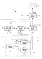
- FIG. 1 is a diagram showing a schematic configuration of an inverter device according to a first embodiment of the present invention.
- an inverter device 1 includes an inverter 2 that converts a DC voltage VDC input from a DC power supply 5 via a DC bus L into a three-phase AC voltage and outputs the three-phase AC voltage to the compressor motor 4; And an inverter control device 3 for controlling the inverter 2.
- the inverter 2 includes upper-arm switching elements S 1u , S 1v , S 1w and lower-arm switching elements S 2u , S 2v , S 2w provided corresponding to the respective phases. By controlling the elements by the inverter control device 3, a three-phase AC voltage supplied to the compressor motor 4 is generated.
- the inverter device 1 includes a current sensor (current detection means) 6 for detecting a direct current i sh flowing through the direct current bus L and a voltage sensor 8 for detecting an input direct current voltage V DC of the inverter 2.
- the DC current i sh detected by the current sensor 6 and the DC voltage V DC detected by the voltage sensor 8 are input to the inverter control device 3.
- an example of the current sensor 6 is a shunt resistor.
- the current sensor 6 is provided on the negative electrode side of the DC power source 5, but may be provided on the positive electrode side.
- the inverter control device 3 is, for example, an MPU (Micro Processing Unit), and has a computer-readable recording medium in which a program for executing each process described below is recorded. The following processing is realized by reading the program recorded in the main memory device such as a RAM and executing it.
- the computer-readable recording medium include a magnetic disk, a magneto-optical disk, and a semiconductor memory.
- FIG. 2 is a functional block diagram showing the functions provided in the inverter control device 3 in an expanded manner.
- the inverter control device 3 includes a current calculation unit 11, a V / f control unit 12, and a PWM signal generation unit 13.
- the current calculator 11 includes an average current calculator 111, a ⁇ -axis current calculator (first current calculator) 112, and a ⁇ -axis current calculator (third current calculator) 113.
- the average current calculation unit 111 calculates the average DC current i sh_ave by averaging the DC current i sh detected by the current sensor 6 with a predetermined sampling period. For example, the average current calculation unit 111 averages the direct current i sh at an electrical angle of 60 ° of any phase current to obtain an average direct current i sh_ave . It should be noted that the averaging of the direct current i sh is not necessarily required, and the averaging may be omitted as long as speed fluctuations and vibration do not become a problem when the motor is driven. In this case, in the calculation of the ⁇ -axis current described later, the ⁇ -axis current i ⁇ is calculated using the DC current sh instead of the average DC current i sh_ave .
- the ⁇ -axis current calculation unit 112 has a ⁇ -axis current calculation formula including the average DC current i sh_ave as a parameter in advance, and the average DC current i sh_ave calculated by the average current calculation unit 111 in the ⁇ -axis current calculation formula. Is substituted for ⁇ -axis current i ⁇ .
- the ⁇ -axis current calculation unit 113 holds in advance a ⁇ -axis current calculation expression including the line voltage command effective value V rms as a parameter.
- the line voltage command effective value V rms is a value determined from a power supply frequency command ⁇ 1 * and two-phase voltage commands v ⁇ * and v ⁇ * used in the V / f control unit 12 described later.
- the ⁇ -axis current calculation unit 113 uses the ⁇ -axis current calculation formula to calculate the line voltage determined from the power supply frequency command ⁇ 1 * and the two-phase voltage commands v ⁇ * and v ⁇ * calculated by the V / f control unit 12.
- the ⁇ -axis current i ⁇ is calculated using the command effective value V rms .
- the line voltage command effective value V rms is calculated by the following equation.
- V rms ⁇ (v ⁇ * 2 + v ⁇ * 2 )
- the ⁇ -axis current and the ⁇ -axis current are each axis current determined using the ⁇ - ⁇ coordinate system.
- the ⁇ - ⁇ coordinate system is an inverter shaft ( ⁇ axis, ⁇ axis) determined for driving the motor without detecting or estimating the rotor position, and the field direction of the rotor position of the motor is the d axis, This corresponds to a dq coordinate system in which the q axis is defined in a direction orthogonal to the d axis.
- an actual effective value (measured value) of the line voltage may be used instead of the line voltage command effective value V rms .
- the line voltage command effective value is calculated from the two-phase voltage commands v ⁇ * and v ⁇ * , but the line voltage command effective value may be calculated from the three-phase voltage command. . Details of the ⁇ -axis current calculation formula held by the ⁇ -axis current calculation unit 112 and the ⁇ -axis current calculation formula held by the ⁇ -axis current calculation unit 113 will be described later.
- the V / f control unit 12 includes a speed / position command generation unit 121, a voltage command generation unit 122, and a two-phase / three-phase conversion unit 123.
- the power supply frequency command ⁇ 1 * is calculated using, for example, the following equation (1).
- ⁇ 1 * n ⁇ m * ⁇ K ⁇ i ⁇ (1)
- n is the number of pole pairs
- ⁇ m * is a rotation axis speed command of the motor
- K ⁇ is a frequency control gain, which is a positive constant.
- the voltage command generator 122 calculates the ⁇ -axis voltage command v ⁇ * from the following equation (3), and calculates the ⁇ -axis voltage command v ⁇ * from the following equation (4).
- lambda [delta] * is an induced voltage coefficient of the compressor motor 5 (counter-electromotive voltage coefficient)
- V Ofsganma is offset voltage is given by the following equation (5).
- K ⁇ is a ⁇ -axis current control gain and is a positive constant.
- Kd is a voltage adjustment gain, which is a positive constant.
- the two-phase / three-phase conversion unit 123 uses the rotor position command ⁇ * to generate a three-phase voltage command v from the ⁇ -axis voltage command v ⁇ * and the ⁇ -axis voltage command v ⁇ * calculated by the voltage command generation unit 122. u *, v v *, v to calculate the w *.
- the ⁇ -axis current i ⁇ and the average DC current i sh_ave are in a proportional relationship, and the ⁇ -axis current i ⁇ is expressed by a linear function of the average DC current i sh_ave .
- the proportionality coefficient ⁇ -axis current conversion coefficient K ⁇
- Equation (6) An equation for calculating the ⁇ -axis current derived from the simulation result is shown in equation (6).
- K ⁇ is a ⁇ -axis current conversion coefficient, which is a value derived from the simulation results shown in FIGS.
- the ⁇ -axis current i ⁇ is substantially constant with respect to the motor torque, and the ⁇ -axis current i ⁇ varies depending on the line voltage command effective value and the rotational axis speed of the motor.
- the inventors set the coordinate space in which the value obtained by dividing the line voltage command effective value by the rotational axis speed of the motor as the horizontal axis and the average value of the ⁇ -axis current i ⁇ as the vertical axis in FIGS.
- the average value of the ⁇ -axis current of each graph shown in Fig. 6 was plotted, and the characteristics at each rotation speed (70%, 85%, 100% with respect to the maximum shaft speed) as shown in Fig.
- K ⁇ is a ⁇ -axis current conversion coefficient
- V rms is a line voltage command effective value
- ⁇ 1 * is a power supply frequency command
- i ⁇ ofs is a ⁇ -axis current offset.
- the ⁇ -axis current conversion coefficient K ⁇ and the ⁇ -axis current offset i ⁇ ofs are values derived from the characteristics shown in FIG. FIG. 6 uses the rotational axis speed of the motor, but in equation (7), the power frequency command is used instead of the rotational axis speed of the motor. This is because the power supply frequency command substantially coincides with the rotational axis speed of the motor, and even if it is substituted, the calculation formula is established.
- the motor control device 3 sets the power supply frequency command ⁇ 1 * to V / f. This is because it is used in control. Thus, the ⁇ -axis current can be easily calculated by diverting the power supply frequency command ⁇ 1 * calculated by the V / f control as it is.
- the DC current i sh and the input DC voltage V DC detected by the current sensor 6 and the voltage sensor 8 are input to the inverter control device 3.
- the average current calculation unit 111 of the current calculation unit 11 of the inverter control device 3 averages the DC current i sh at a predetermined sampling period, and the average DC current i sh_ave is supplied to the ⁇ -axis current calculation unit 112 and the ⁇ -axis current calculation unit 113. Output.
- the ⁇ -axis current calculation unit 112 holds the above equation (6) in advance, and substitutes the average DC current i sh_ave input from the average current calculation unit 111 into the above equation (6), thereby obtaining the ⁇ -axis current i. ⁇ is calculated. Further, the ⁇ -axis current calculation unit 113 holds the above equation (7) in advance, and the latest power frequency command ⁇ 1 * , ⁇ -axis voltage command v ⁇ * , and ⁇ -axis from the V / f control unit 12. A voltage command v ⁇ * is input.
- the ⁇ -axis current calculation unit 113 calculates the line voltage command effective value V rms from the ⁇ -axis voltage command v ⁇ * and the ⁇ -axis voltage command v ⁇ * . Further, the ⁇ -axis current i ⁇ is calculated by substituting the line voltage command effective value V rms and the input power frequency command ⁇ 1 * into the above equation (7).
- the ⁇ -axis current i ⁇ calculated by the ⁇ -axis current calculation unit 112 and the ⁇ -axis current i ⁇ calculated by the ⁇ -axis current calculation unit 113 are input to the V / f control unit 12 to generate a three-phase voltage command. Used. Specifically, the speed / position command generation unit 121 of the V / f control unit 12 calculates the power supply frequency command ⁇ 1 * by substituting the ⁇ -axis current i ⁇ into the above equation (1). Further, the rotor position command ⁇ * is calculated by integrating the power supply frequency command.
- the power supply frequency command ⁇ 1 * and the ⁇ -axis current i ⁇ are used, and from the equations (3) and (4), the ⁇ -axis voltage command v ⁇ * and the ⁇ -axis voltage command. v ⁇ * is calculated.
- the rotor position command ⁇ * calculated by the speed / position command generator 121 is used, and the ⁇ -axis voltage commands v ⁇ * and ⁇ calculated by the voltage command generator 122 are used.
- the shaft voltage command v ⁇ * is converted into a three-phase voltage command v u * , v v * , v w * .
- the three-phase voltage commands v u * , v v * and v w * calculated by the V / f control unit 12 are input to the PWM signal generation unit 13 and together with the value of the input DC voltage V DC input to the inverter 2.
- the PWM signal S PWM corresponding to each phase is used for generation.
- the PWM signal of each phase generated by the PWM signal generation unit 13 is given to the inverter 2, and the switching elements of the upper arm and the lower arm corresponding to each phase of the inverter 2 are on / off controlled based on this PWM signal. .
- the average DC current, the ⁇ -axis current, and the ⁇ with respect to the motor torque when the line voltage command effective value and the rotation shaft speed of the motor are changed, respectively.
- determined relationship axis current respectively, define a calculation formula for calculating the gamma-axis current i gamma and [delta] -axis current i [delta] from the relation, respectively, gamma-axis current by using the arithmetic expression i gamma and [delta] -axis current i [delta] Is calculated.
- FIG. 7 only one phase switching element (W phase in FIG.
- the ⁇ -axis current i ⁇ is calculated from the average DC current i sh_ave and the ⁇ -axis current i ⁇ is calculated using the parameters used for V / f control. . Therefore, for example, the step of calculating the inverter output currents iu, iv, iw described in Patent Document 3 can be omitted. Thereby, the processing burden in the inverter control apparatus 3 can be reduced. As a result, since there is room in the processing in the inverter control device 3, it is possible to realize, for example, shortening the control cycle and increasing the carrier frequency.
- the configuration of the V / f control unit 12 is an example.
- a known V / f control configuration for example, a V / f as disclosed in Patent Document 1 is used. It is possible to adopt a control configuration.
- the inverter control device 3 controls the inverter by using other control methods such as sensorless vector control, open loop control, equi-width PWM control in addition to the V / f control unit 12.
- the control unit may be provided. For example, according to the speed command of the compressor motor 4, one control method is selected from open loop control, equal width PWM control, sensorless vector control, and V / f control, and the inverter 2 is controlled according to the control method. You may do it.
- the period during which the V / f control by the V / f control unit 12 is being performed is a current calculation unit. performs calculation of gamma-axis current i gamma and [delta] -axis current i [delta] with 11, the calculated gamma-axis current i gamma and [delta] -axis current i [delta] has been decided to use the V / f control.
- the inverter device calculates the ⁇ -axis current i ⁇ and the ⁇ -axis current i ⁇ by the current calculation unit 11 only during the period in which the overmodulation control is performed in the V / f control, and performs the overmodulation control. During the period when the current is not performed, the ⁇ -axis current i ⁇ and the ⁇ -axis current i ⁇ are calculated using another axial current calculation method.
- the inverter device 1a is a method disclosed in Patent Document 3, that is, a direct current i sh to a three-phase current i u .
- a current calculation unit (third current calculation means, fourth current) that calculates i v , i w and calculates a ⁇ -axis current i ⁇ and a ⁇ -axis current i ⁇ from the calculated three-phase currents i u , i v , i w Calculation means) 20 is provided.
- the current calculation unit 20 includes a phase current calculation unit 21 and a three-phase / two-phase conversion unit 22.
- the current calculation unit 11 when overmodulation control is performed, the current calculation unit 11 is used to calculate the ⁇ -axis current i ⁇ and the ⁇ -axis current i ⁇ , and overmodulation control is not performed.
- the current calculator 20 is used to calculate the ⁇ -axis current i ⁇ and the ⁇ -axis current i ⁇ .
- the determination whether or not overmodulation control is performed may be performed based on, for example, a voltage utilization rate.
- the voltage utilization rate is given by the following equation (8).
- Voltage utilization rate Line voltage command effective value / (DC voltage / ⁇ 2) (8)
- the current calculation unit 11 when the voltage usage rate is equal to or greater than a predetermined value (for example, 1) set in advance, it is determined that overmodulation control is being performed, and the current calculation unit 11 is employed so that the voltage usage rate is predetermined. If the value is less than the value, it is determined that overmodulation control is not performed, and the current calculation unit 20 is employed.
- a predetermined value for example, 1
- the negative side switching element corresponding to one phase or two phases is turned on over a period of one control period or more, and the negative side switching corresponding to the remaining phase is turned on.
- the current calculation unit 11 may be employed when the element is turned off, and the current calculation unit 20 may be employed in other cases. Whether only the negative-side switching element corresponding to one phase or two-phase is turned on and the negative-side switching elements corresponding to the remaining phases are turned off is, for example, 3 calculated by the V / f control unit 12 It is possible to determine whether any phase of the phase voltage commands v u * , v v * , and v w * exceeds the maximum value of the carrier triangular wave amplitude.
- the current calculation unit 20 is employed to calculate the ⁇ -axis current i ⁇ and the ⁇ -axis current i ⁇ .
- the current calculation unit 11 may be employed to calculate the ⁇ -axis current i ⁇ and the ⁇ -axis current i ⁇ .
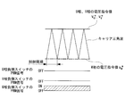
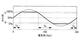
- the first period Ta is equal to or less than the upper limit A of the duty ratio that can secure the time required for the inverter control device (for example, CPU) to detect the current value
- the inverter control device This is a period of time equal to or higher than the lower limit B of the duty ratio that can secure the time required to detect the current value.
- the switching between the current calculation unit 11 and the current calculation unit 20 may be performed only for the ⁇ -axis current or only for the ⁇ -axis current.
- the ⁇ -axis current i ⁇ may be always performed using the ⁇ -axis current calculation unit 112 of the current calculation unit 11 without switching the current calculation unit.
- the calculated value may vary before and after the switching. Therefore, by calculating either one of the ⁇ -axis current i ⁇ and the ⁇ -axis current i ⁇ with the same method, it is possible to suppress fluctuations in the calculated value accompanying the switching of the calculation method. .
- the inverter device includes a ⁇ -axis current calculation unit (first current calculation unit) 112 in the current calculation unit 11 (see FIG. 2) and a ⁇ -axis in the current calculation unit 20.
- a current calculation function (second current calculation means), and the ⁇ -axis current calculated by the ⁇ -axis current calculation unit 112 and the ⁇ -axis current calculated by the current calculation unit 20 are V / f controlled. Is output to the unit 12.
- the current calculation unit 20 stops the ⁇ -axis current calculation process, holds the ⁇ -axis current i ⁇ calculated in the immediately preceding first period Ta, and sets this value as ⁇ . Output as shaft current i ⁇ .
- the ⁇ -axis current calculation unit 112 continues to calculate the ⁇ -axis current.
- the value of the last ⁇ -axis current i ⁇ calculated in the first period Ta is held by the current calculation unit 20, and V / f is used by using this value.
- the control unit 12 performs the calculations of the above-described equations (3) to (5) to calculate the ⁇ -axis voltage command v ⁇ * and the ⁇ -axis voltage command v ⁇ * .
- the current calculation unit 20 is employed as the ⁇ -axis current calculation unit, but instead, the ⁇ -axis current calculation unit 113 illustrated in FIG. 1 may be employed. Also in this case, by stopping the calculation process of the ⁇ -axis current i ⁇ in the period other than the first period Ta, it is possible to reduce the processing load and the consumption output.
- an inverter device according to a fourth embodiment of the present invention will be described.
- the previous value is used as the ⁇ -axis current in a period other than the first period Ta during execution of overmodulation control.
- current calculation is performed in a period other than the first period Ta.
- the calculation process of the ⁇ -axis current in the unit 20 is stopped, and the calculation process of the equations (4) and (5) in the V / f control unit 12 is stopped.
- the V / f control unit 12 adopts a constant value set in advance as the ⁇ -axis voltage command v ⁇ * , and does not perform calculation processing for Equation (5), The value of V ofs ⁇ at is treated as constant.
- the calculation process of the ⁇ -axis current is stopped and the calculation processes of the expressions (4) and (5) in the V / f control unit 12 are also stopped.
- the arithmetic processing can be simplified, and the processing burden on the current calculation unit 11 and the V / f control unit 12 can be reduced.
- the calculation process using the equation (4) is stopped throughout the overmodulation control execution period, and a preset constant value is adopted. It is good.
Landscapes
- Engineering & Computer Science (AREA)
- Power Engineering (AREA)
- Inverter Devices (AREA)
- Control Of Ac Motors In General (AREA)
Abstract
過変調制御が実行されている全ての期間において、1つの電流センサによる電流検出により、安定したインバータ制御を実現することを目的とする。インバータ制御装置(3)は、直流電流をパラメータとして含むγ軸電流演算式を予め保有し、γ軸電流演算式に電流センサにより検出された直流電流を用いてγ軸電流を算出するγ軸電流算出部112を有する。
Description
本発明は、インバータ装置に関するものである。
従来、インバータ装置によるモータの駆動制御方法として、V/fベクトル制御が知られている(例えば、特許文献1参照)。更に、V/fベクトル制御において、電圧利用率を1以上とする制御方法である過変調制御が知られている(例えば、特許文献2参照)。
また、インバータ装置によるモータ制御においては、インバータからモータへ流れる3相交流電流を検出する必要がある。この3相交流電流の検出方法として、例えば、特許文献3には、インバータの入力側に設けられた1つの電流センサによって、3相交流電流を検出する方法が開示されている。具体的には、特許文献3には、インバータが備える各相に対応するスイッチング素子のオンオフによって、PWMインバータの直流電流に、二相の電流情報が現れることを利用し、スイッチング素子のオンオフ情報を元に、サンプリングした直流入力電流を各相別に分配して3相の電流検出値として検出する技術が開示されている。
ところで、例えば、上述した特許文献2に開示されているような過変調制御では、インバータを構成する下側アームのスイッチング素子のうち、1相を1制御周期以上の期間に渡ってオン状態とするとともに、2相をオフ状態とするような制御が行われる場合がある(例えば、図7参照)。一方、上記特許文献3に開示されているモータ電流検出方法では、スイッチング素子のオンオフによって、直流電流に二相の電流情報が現れることを利用している。このため、1制御周期内にスイッチングによる電流変化が生じることが電流検出の条件となる。
したがって、例えば、過変調制御実施中に図7のようなスイッチング状態となった場合には、特許文献3に開示されている技術による電流検出が不可能となり、安定したインバータ制御が実現できないという問題があった。
したがって、例えば、過変調制御実施中に図7のようなスイッチング状態となった場合には、特許文献3に開示されている技術による電流検出が不可能となり、安定したインバータ制御が実現できないという問題があった。
本発明は、過変調制御が実行されている全ての期間において、1つの電流センサによる電流検出により、安定したインバータ制御を実現することのできるインバータ装置を提供することを目的とする。
本発明の第1態様は、直流母線を介して入力される直流電圧を三相交流電圧に変換してモータに出力するインバータと、前記インバータを制御するインバータ制御手段と、前記直流母線に流れる直流電流を検出する電流検出手段とを備え、前記インバータ制御手段は、前記直流電流をパラメータとして含むγ軸電流演算式を予め保有し、該γ軸電流演算式に前記電流検出手段により検出された直流電流を用いてγ軸電流を算出する第1電流算出手段を具備するインバータ装置である。
上記構成によれば、γ軸電流算出手段が、直流電流をパラメータとしたγ軸電流を算出するための演算式を予め保有しており、この演算式を用いてγ軸電流を算出するので、直流電流が検出できれば、γ軸電流を得ることができる。これにより、電流センサとして1つの電流センサしか設けられておらず、かつ、過変調制御が行われている全ての期間においても、γ軸電流を得ることが可能となる。
上記直流電流のパラメータとは、直流電流を平均化処理して求められる平均直流電流など、直流電流を用いて定められる直流電流に関するパラメータも含むものとする。
上記直流電流のパラメータとは、直流電流を平均化処理して求められる平均直流電流など、直流電流を用いて定められる直流電流に関するパラメータも含むものとする。
上記インバータ装置において、前記γ軸電流演算式は、例えば、線間電圧及びモータの回転軸速度をそれぞれ変化させたときのモータトルクに対する平均直流電流およびγ軸電流の関係を求め、該関係から導出された式である。
上記インバータ装置において、前記インバータ制御手段は、前記電流検出手段によって検出された直流電流から3相交流電流を算出し、該3相交流電流からδ軸電流を算出する第2電流算出手段を備えることとしてもよい。
上記インバータ装置において、前記インバータ制御手段は、前記第1電流算出手段によって算出されたγ軸電流および前記第2電流算出手段によって算出されたδ軸電流が入力されるV/f制御手段を備え、前記V/f制御手段は、γ軸電流と前記モータの速度指令とを用いて電源周波数指令を算出する電源周波数指令算出手段と、δ軸電流の積分項及び前記電源周波数指令をパラメータとして含む演算式を用いてγ軸電圧指令を算出するγ軸電圧指令算出手段と、前記δ軸電流の一次関数を用いてδ軸電圧指令を算出するδ軸電圧指令算出手段とを有することとしてもよい。
上記インバータ装置において、前記第2電流算出手段は、過変調制御実行中において電気角1周期の中にデューティ比が100%及び0%以外となる第1期間である場合に、前記3相交流電流からδ軸電流を算出し、前記第1期間以外の期間においては、前記第1期間において直前に算出されたδ軸電流を保持し、保持した値をδ軸電流として出力することとしてもよい。
このように、前記第1期間以外の期間において、第2電流算出手段が算出処理を行わずに保持している前回値を出力することで、処理負担の軽減や消費電力の低減を図ることが可能となる。
ここで、「第1期間」とは、インバータ制御装置(例えば、CPU)が電流値を検出するのに必要な時間を確保することができるデューティ比の上限以下であり、かつ、インバータ制御装置が電流値を検出するのに必要な時間を確保することができるデューティ比の下限以上である期間をいう。
ここで、「第1期間」とは、インバータ制御装置(例えば、CPU)が電流値を検出するのに必要な時間を確保することができるデューティ比の上限以下であり、かつ、インバータ制御装置が電流値を検出するのに必要な時間を確保することができるデューティ比の下限以上である期間をいう。
上記インバータ装置においては、過変調制御実行中において、電気角1周期の中にデューティ比が100%及び0%である期間においては、前記第2電流算出手段は、前記δ軸電流の算出処理を停止し、前記γ軸電圧指令算出手段は、前記δ軸電流の積分項に予め設定された一定値を用いて前記γ軸電圧指令を算出することとしてもよい。
このように、過変調制御実行中において、電気角1周期の中にデューティ比が100%及び0%である期間においては、δ軸電流の算出処理を停止するとともに、V/f制御手段におけるδ軸電流の積分項の算出処理を停止するので、演算処理を簡素化でき、インバータ制御手段の処理負担を軽減させることが可能となる。
上記インバータ装置においては、過変調制御実行中において、前記δ軸電圧指令算出手段は、前記δ軸電圧指令として予め設定されている一定値を出力することとしてもよい。
このように、過変調制御実行中において、V/f制御手段におけるδ軸電圧指令の算出処理を停止するので、演算処理を簡素化でき、インバータ制御手段の処理負担を軽減させることが可能となる。
上記インバータ装置において、前記インバータ制御手段は、前記第1電流算出手段によって算出されたγ軸電流が入力され、該γ軸電流と前記モータの速度指令とを用いて電源周波数指令を算出するV/f制御手段と、線間電圧および前記V/f制御手段において算出される前記電源周波数指令をパラメータとして含むδ軸電流演算式を予め保有し、該δ軸電流演算式に、前記線間電圧の指令値または計測値及び前記V/f制御手段で算出された前記電源周波数指令を用いてδ軸電流を算出する第3電流算出手段とを具備することとしてもよい。
上記構成によれば、第3電流算出手段は、δ軸電流を算出するための演算式を予め保有しており、この演算式を用いてδ軸電流を算出する。これにより、電流センサとして1つの電流センサしか設けられておらず、かつ、過変調制御が行われている全ての期間においても、δ軸電流を得ることが可能となる。
上記インバータ装置において、前記δ軸電流演算式は、例えば、線間電圧及びモータの回転軸速度をそれぞれ変化させたときのモータトルクに対するδ軸電流の関係を求め、該関係から導出された式である。
上記インバータ装置は、前記電流検出手段によって検出された直流電流から3相交流電流を算出し、該3相交流電流からγ軸電流を算出する第4電流算出手段と、算出した前記3相交流電流からδ軸電流を算出する第2電流算出手段とを有し、過変調制御が実行されている期間は、前記第1電流算出手段によりγ軸電流を算出するとともに前記第3電流算出手段により前記δ軸電流を算出し、前記過変調制御が行われていない期間においては、前記第4電流算出手段によりγ軸電流を算出するとともに前記第2電流算出手段によりδ軸電流を算出することとしてもよい。
上記インバータ装置においては、過変調制御実行中において、電気角1周期の中にデューティ比が100%及び0%以外となる第1期間である場合に、前記第4電流算出手段によりγ軸電流を算出するとともに、前記第2電流算出手段によりδ軸電流を算出し、前記第1期間以外の期間においては、前記第1の電流算出手段によりγ軸電流を算出し、前記第3電流算出手段によりδ軸電流を算出することとしてもよい。
本発明によれば、過変調制御が実行されている全ての期間において、1つの電流センサによる電流検出により、安定したインバータ制御を実現することができるという効果を奏する。
以下に、本発明に係るインバータ装置を車載の空気調和機に使用される圧縮機モータに適用した場合の一実施形態について、図面を参照して説明する。なお、本発明に係るインバータ装置は、以下に説明する圧縮機モータのみに適用されるものではなく、モータ全般に広く適用することができる。
〔第1実施形態〕
図1は、本発明の第1実施形態に係るインバータ装置の概略構成を示した図である。図1に示されるように、インバータ装置1は、直流電源5から直流母線Lを介して入力される直流電圧VDCを三相交流電圧に変換して圧縮機モータ4に出力するインバータ2と、インバータ2を制御するインバータ制御装置3とを備えている。
図1は、本発明の第1実施形態に係るインバータ装置の概略構成を示した図である。図1に示されるように、インバータ装置1は、直流電源5から直流母線Lを介して入力される直流電圧VDCを三相交流電圧に変換して圧縮機モータ4に出力するインバータ2と、インバータ2を制御するインバータ制御装置3とを備えている。
インバータ2は、各相に対応して設けられた上側アームのスイッチング素子S1u、S1v、S1wと下側アームのスイッチング素子S2u、S2v、S2wとを備えており、これらのスイッチング素子がインバータ制御装置3により制御されることにより、圧縮機モータ4に供給される3相交流電圧が生成される。
また、インバータ装置1は、直流母線Lに流れる直流電流ishを検出するための電流センサ(電流検出手段)6及びインバータ2の入力直流電圧VDCを検出する電圧センサ8を備えている。
電流センサ6により検出された直流電流ish及び電圧センサ8により検出された直流電圧VDCはインバータ制御装置3に入力される。ここで、電流センサ6の一例としては、シャント抵抗が挙げられる。なお、図1では、電流センサ6を直流電源5の負極側に設けているが、正極側に設けることとしてもよい。
電流センサ6により検出された直流電流ish及び電圧センサ8により検出された直流電圧VDCはインバータ制御装置3に入力される。ここで、電流センサ6の一例としては、シャント抵抗が挙げられる。なお、図1では、電流センサ6を直流電源5の負極側に設けているが、正極側に設けることとしてもよい。
インバータ制御装置3は、例えば、MPU(Micro Processing Unit)であり、以下に記載する各処理を実行するためのプログラムが記録されたコンピュータ読み取り可能な記録媒体を有しており、CPUがこの記録媒体に記録されたプログラムをRAM等の主記憶装置に読み出して実行することにより、以下の各処理が実現される。コンピュータ読み取り可能な記録媒体としては、例えば、磁気ディスク、光磁気ディスク、半導体メモリ等が挙げられる。
インバータ制御装置3は、圧縮機モータ4の回転速度が上位の制御装置(図示略)から与えられるモータ速度指令に一致させるようなPWM信号SPWMを相毎に生成し、これらをインバータ2の各相に対応するスイッチング素子に与えることでインバータ3を制御し、所望の3相交流電圧を圧縮機モータ4に供給する。
図2は、インバータ制御装置3が備える機能を展開して示した機能ブロック図である。
図2に示すように、インバータ制御装置3は、電流算出部11、V/f制御部12、およびPWM信号生成部13を備えている。
図2に示すように、インバータ制御装置3は、電流算出部11、V/f制御部12、およびPWM信号生成部13を備えている。
電流算出部11は、平均電流算出部111と、γ軸電流算出部(第1電流算出手段)112と、δ軸電流算出部(第3電流算出手段)113とを備えている。
平均電流算出部111は、電流センサ6により検出された直流電流ishを所定のサンプリング周期で平均化して平均直流電流ish_aveを算出する。平均電流算出部111は、例えば、いずれかの相電流の電気角60°周期で直流電流ishを平均化し、平均直流電流ish_aveを得る。なお、直流電流ishの平均化は、必ずしも必要ではなく、モータ駆動時において速度変動や振動が問題にならないような程度であれば、平均化は省略してもよい。この場合には、後述のγ軸電流の算出においては、平均直流電流ish_aveに代えて直流電流shを用いてγ軸電流iγの算出が行われる。
平均電流算出部111は、電流センサ6により検出された直流電流ishを所定のサンプリング周期で平均化して平均直流電流ish_aveを算出する。平均電流算出部111は、例えば、いずれかの相電流の電気角60°周期で直流電流ishを平均化し、平均直流電流ish_aveを得る。なお、直流電流ishの平均化は、必ずしも必要ではなく、モータ駆動時において速度変動や振動が問題にならないような程度であれば、平均化は省略してもよい。この場合には、後述のγ軸電流の算出においては、平均直流電流ish_aveに代えて直流電流shを用いてγ軸電流iγの算出が行われる。
γ軸電流算出部112は、平均直流電流ish_aveをパラメータとして含むγ軸電流演算式を予め保有しており、このγ軸電流演算式に平均電流算出部111によって算出された平均直流電流ish_aveを代入することにより、γ軸電流iγを算出する。
δ軸電流算出部113は、線間電圧指令実効値Vrmsをパラメータとして含むδ軸電流演算式を予め保有している。ここで、線間電圧指令実効値Vrmsは、後述するV/f制御部12で用いられる電源周波数指令ω1
*および2相電圧指令vγ
*,vδ
*から定められる値である。δ軸電流算出部113は、このδ軸電流演算式に、V/f制御部12で算出された電源周波数指令ω1
*および2相電圧指令vγ
*,vδ
*から定められる線間電圧指令実効値Vrmsを用いて、δ軸電流iδを算出する。
上記線間電圧指令実効値Vrmsは、以下の式で算出される。
上記線間電圧指令実効値Vrmsは、以下の式で算出される。
Vrms=√(vδ
*2+vγ
*2)
ここで、γ軸電流及びδ軸電流とは、δ-γ座標系を用いて定められる各軸電流である。δ-γ座標系は、回転子位置の検出または推定を行わずにモータを駆動する為に定めるインバータ軸(γ軸、δ軸)であり、モータの回転子位置の界磁方向をd軸、d軸と直交する方向にq軸を定めたd-q座標系に対応する。
なお、δ軸電流iδの算出においては、線間電圧指令実効値Vrmsに代えて、実際の線間電圧の実効値(計測値)を用いることとしてもよい。また、上記例では、2相電圧指令vγ *,vδ *から線間電圧指令実効値を算出することとしたが、3相電圧指令から線間電圧指令実効値を算出することとしてもよい。
また、γ軸電流算出部112が保有するγ軸電流演算式及びδ軸電流算出部113が保有するδ軸電流演算式の詳細については、後述する。
なお、δ軸電流iδの算出においては、線間電圧指令実効値Vrmsに代えて、実際の線間電圧の実効値(計測値)を用いることとしてもよい。また、上記例では、2相電圧指令vγ *,vδ *から線間電圧指令実効値を算出することとしたが、3相電圧指令から線間電圧指令実効値を算出することとしてもよい。
また、γ軸電流算出部112が保有するγ軸電流演算式及びδ軸電流算出部113が保有するδ軸電流演算式の詳細については、後述する。
V/f制御部12は、速度・位置指令生成部121、電圧指令生成部122、2相/3相変換部123を備えている。
速度・位置指令生成部121は、圧縮機モータ4の回転軸速度指令ωm
*とγ軸電流算出部112により算出されたγ軸電流iγとを用いて、電源周波数指令(圧縮機モータ4に供給する3相交流電圧の角周波数指令)ω1
*を算出する。
電源周波数指令ω1
*は、例えば、以下の(1)式を用いて算出される。
ω1
*=nωm
*-Kωiγ (1)
(1)式において、nは極対数、ωm
*はモータの回転軸速度指令、Kωは周波数制御ゲインであり正の定数である。
(1)式によれば、γ軸電流iγが増加した場合、すなわち、モータ負荷が増加した場合には、電源周波数指令ω1 *を減少させる。一方、γ軸電流iγが減少した場合、すなわち、モータ負荷が減少した場合には、電源周波数指令ω1 *を増加させる。このように制御することで、モータ負荷が増加した場合には、電源周波数指令ω1 *を減少させることによって失速を防止し、モータ負荷が減少した時には、電源周波数指令ω1 *を増加させることによってモータの加速を抑制することが可能となる。
(1)式によれば、γ軸電流iγが増加した場合、すなわち、モータ負荷が増加した場合には、電源周波数指令ω1 *を減少させる。一方、γ軸電流iγが減少した場合、すなわち、モータ負荷が減少した場合には、電源周波数指令ω1 *を増加させる。このように制御することで、モータ負荷が増加した場合には、電源周波数指令ω1 *を減少させることによって失速を防止し、モータ負荷が減少した時には、電源周波数指令ω1 *を増加させることによってモータの加速を抑制することが可能となる。
更に、速度・位置指令生成部121は、電源周波数指令ω1
*を積分することにより、ロータの位置指令θ*を算出する。ロータの位置指令θ*の算出式は、以下の(2)式で与えられる。
θ*=∫ω1
*dt (2)
電圧指令生成部122は、以下の(3)式からγ軸電圧指令vγ
*を、以下の(4)式からδ軸電圧指令vδ
*を算出する。
vγ
*=Λδ
*ω1
*+Vofsγ (3)
vδ *=-Kδiδ (4)
vδ *=-Kδiδ (4)
(3)式において、Λδ
*は圧縮機モータ5の誘起電圧係数(逆起電圧係数)、Vofsγはオフセット電圧であり、以下の(5)式で与えられる。また、(4)式において、Kδはδ軸電流制御ゲインであり正の定数である。
Vofsγ=-Kd∫iδdt (5)
上記(5)式において、Kdは電圧調整ゲインであり、正の定数である。
2相/3相変換部123は、ロータの位置指令θ*を用いて、電圧指令生成部122において算出されたγ軸電圧指令vγ
*及びδ軸電圧指令vδ
*から3相電圧指令vu
*、vv
*、vw
*を算出する。
PWM信号生成部13は、V/f制御部12で算出された3相電圧指令vu
*、vv
*、vw
*を用いて、各相に対応するPWM信号SPWMを生成する。また、PWM信号SPWMの生成には、インバータ3に入力される入力直流電圧VDCが用いられる。
次に、本発明の主たる特徴の一つである電流算出部11で用いられるγ軸電流演算式およびδ軸電流演算式について詳しく説明する。
発明者らは、シミュレーションを行うことにより、線間電圧指令実効値及びモータの回転軸速度をそれぞれ変化させたときのモータトルクに対する平均直流電流ish_aveとγ軸電流iγ及びδ軸電流iδの関係を求めた。
図3から図5にシミュレーション結果を示す。図3から図5に示されたグラフにおいて、縦軸は電流であり、横軸はモータトルクである。図3はモータの回転軸速度が低速度のとき、例えば、回転軸速度を最大の回転軸速度に対して70%以上80%未満に設定したときのシミュレーション結果、図4はモータの回転軸速度が中速度、例えば、回転軸速度を最大の回転軸速度に対して80%以上90%未満に設定したときのシミュレーション結果、図5はモータの回転軸速度が高速度のとき、例えば、回転時速度を最大の回転軸速度に対して90%以上100%以下に設定した時のシミュレーション結果を示している。また、図3から図5において、線間電圧指令実効値は、図3(a)から図5(c)の順で、徐々に高くなっている。また、各特性は、モータトルクによっては過変調制御になるような線間電圧指令実効値及びモータの回転軸速度を対象として求められたものである。
図3から図5にシミュレーション結果を示す。図3から図5に示されたグラフにおいて、縦軸は電流であり、横軸はモータトルクである。図3はモータの回転軸速度が低速度のとき、例えば、回転軸速度を最大の回転軸速度に対して70%以上80%未満に設定したときのシミュレーション結果、図4はモータの回転軸速度が中速度、例えば、回転軸速度を最大の回転軸速度に対して80%以上90%未満に設定したときのシミュレーション結果、図5はモータの回転軸速度が高速度のとき、例えば、回転時速度を最大の回転軸速度に対して90%以上100%以下に設定した時のシミュレーション結果を示している。また、図3から図5において、線間電圧指令実効値は、図3(a)から図5(c)の順で、徐々に高くなっている。また、各特性は、モータトルクによっては過変調制御になるような線間電圧指令実効値及びモータの回転軸速度を対象として求められたものである。
図3から図5に示されるように、γ軸電流iγと平均直流電流ish_aveとは比例関係にあり、γ軸電流iγは平均直流電流ish_aveの一次関数で表わされることがわかった。
また、比例係数(γ軸電流換算係数Kγ)は、回転速度や線間電圧指令実効値によらず、一定値で表現できることも分かった。シミュレーション結果から導出されたγ軸電流演算式を(6)式に示す。
また、比例係数(γ軸電流換算係数Kγ)は、回転速度や線間電圧指令実効値によらず、一定値で表現できることも分かった。シミュレーション結果から導出されたγ軸電流演算式を(6)式に示す。
iγ=Kγ×ish_ave (6)
上記(6)式において、Kγはγ軸電流換算係数であり、図3から図5に示したシミュレーション結果から導出される値である。
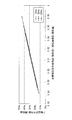
上記γ軸電流iγに対し、δ軸電流iδはモータトルクに対してほぼ一定であり、また、δ軸電流iδは、線間電圧指令実効値とモータの回転軸速度によって変化することが分かった。そこで、発明者らは、線間電圧指令実効値をモータの回転軸速度で除算した値を横軸とし、δ軸電流iδの平均値を縦軸とした座標空間に、図3から図5に示された各グラフのδ軸電流の平均値をプロットし、図6に示すような回転速度(最大軸速度に対する70%、85%、100%)毎の特性を得た。図6からδ軸電流iδの平均値は、線間電圧指令実効値をモータの回転軸速度で除した値の一次関数とおくことができることが分かった。シミュレーション結果から導出されたδ軸電流演算式を(7)式に示す。
iδ=Kδ(Vrms/ω1
*)+iδofs (7)
(7)式において、Kδはδ軸電流換算係数、Vrmsは線間電圧指令実効値、ω1
*は電源周波数指令、iδofsはδ軸電流オフセットである。ここで、δ軸電流換算係数Kδ及びδ軸電流オフセットiδofsは、図6に示した特性から導出される値である。また、図6はモータの回転軸速度を用いているが、(7)式ではモータの回転軸速度に代えて電源周波数指令を用いることとした。この理由は、電源周波数指令はモータの回転軸速度とほぼ一致しており、代用しても演算式が成立するとともに、上述のようにモータ制御装置3では電源周波数指令ω1
*をV/f制御において利用しているからである。このように、V/f制御で算出した電源周波数指令ω1
*をそのまま流用することで、δ軸電流を容易に算出することができる。
次に、本実施形態に係るインバータ制御装置3の作用について説明する。
まず、電流センサ6及び電圧センサ8によって検出された直流電流ish及び入力直流電圧VDCは、インバータ制御装置3に入力される。インバータ制御装置3の電流算出部11の平均電流算出部111は、直流電流ishを所定のサンプリング周期で平均化し、平均直流電流ish_aveをγ軸電流算出部112及びδ軸電流算出部113に出力する。
まず、電流センサ6及び電圧センサ8によって検出された直流電流ish及び入力直流電圧VDCは、インバータ制御装置3に入力される。インバータ制御装置3の電流算出部11の平均電流算出部111は、直流電流ishを所定のサンプリング周期で平均化し、平均直流電流ish_aveをγ軸電流算出部112及びδ軸電流算出部113に出力する。
γ軸電流算出部112は、上記(6)式を予め保有しており、上記(6)式に平均電流算出部111から入力された平均直流電流ish_aveを代入することにより、γ軸電流iγを算出する。
また、δ軸電流算出部113は、上記(7)式を予め保有しているとともに、V/f制御部12から最新の電源周波数指令ω1 *、γ軸電圧指令vγ *、及びδ軸電圧指令vδ *が入力される。δ軸電流算出部113は、γ軸電圧指令vγ *及びδ軸電圧指令vδ *から線間電圧指令実効値Vrmsを算出する。更に、この線間電圧指令実効値Vrmsと入力された電源周波数指令ω1 *とを上記(7)式に代入することにより、δ軸電流iδを算出する。
また、δ軸電流算出部113は、上記(7)式を予め保有しているとともに、V/f制御部12から最新の電源周波数指令ω1 *、γ軸電圧指令vγ *、及びδ軸電圧指令vδ *が入力される。δ軸電流算出部113は、γ軸電圧指令vγ *及びδ軸電圧指令vδ *から線間電圧指令実効値Vrmsを算出する。更に、この線間電圧指令実効値Vrmsと入力された電源周波数指令ω1 *とを上記(7)式に代入することにより、δ軸電流iδを算出する。
γ軸電流算出部112により算出されたγ軸電流iγ及びδ軸電流算出部113により算出されたδ軸電流iδは、V/f制御部12へ入力され、3相電圧指令の生成に利用される。
具体的には、V/f制御部12の速度・位置指令生成部121において、γ軸電流iγが上記(1)式に代入されることにより電源周波数指令ω1 *が算出される。更に、電源周波数指令が積分されることにより、ロータの位置指令θ*が算出される。
具体的には、V/f制御部12の速度・位置指令生成部121において、γ軸電流iγが上記(1)式に代入されることにより電源周波数指令ω1 *が算出される。更に、電源周波数指令が積分されることにより、ロータの位置指令θ*が算出される。
続いて、電圧指令生成部122において、電源周波数指令ω1
*とδ軸電流iδとが用いられて、(3)式および(4)式からγ軸電圧指令vγ
*及びδ軸電圧指令vδ
*が算出される。
2相/3相変換部124では、速度・位置指令生成部121において算出されたロータの位置指令θ*が用いられて、電圧指令生成部122において算出されたγ軸電圧指令vγ
*及びδ軸電圧指令vδ
*が3相電圧指令vu
*、vv
*、vw
*に変換される。
V/f制御部12において算出された3相電圧指令vu
*、vv
*、vw
*は、PWM信号生成部13に入力され、インバータ2に入力される入力直流電圧VDCの値とともに、各相に対応するPWM信号SPWMの生成に利用される。PWM信号生成部13により生成された各相のPWM信号は、インバータ2に与えられ、このPWM信号に基づいてインバータ2の各相に対応する上側アーム及び下側アームのスイッチング素子がオンオフ制御される。
以上説明したように、本実施形態に係るインバータ装置1によれば、線間電圧指令実効値及びモータの回転軸速度をそれぞれ変化させたときのモータトルクに対する平均直流電流、γ軸電流、及びδ軸電流の関係をそれぞれ求め、該関係からγ軸電流iγおよびδ軸電流iδを算出するための演算式をそれぞれ定め、この演算式を用いてγ軸電流iγおよびδ軸電流iδを算出する。これにより、図7に示すように、1制御周期以上の期間に渡って一相(図7ではW相)のスイッチング素子のみがオン状態とされ、他の2相に対応するスイッチング素子がオフ状態とされるような過変調制御が実行されている場合でも、1つの電流センサ6によって検出される直流電流ishに基づいて、γ軸電流iγおよびδ軸電流iδを得ることが可能となる。
更に、本実施形態に係るインバータ装置1によれば、平均直流電流ish_aveからγ軸電流iγを算出するとともに、V/f制御に用いられるパラメータを使用してδ軸電流iδを算出する。従って、例えば、特許文献3などに述べられているインバータ出力電流iu,iv,iwを算出するステップを省略することができる。これにより、インバータ制御装置3における処理負担を軽減することができる。この結果、インバータ制御装置3における処理に余裕ができることから、例えば、制御周期の短縮化や、キャリア周波数の高周波化を実現することが可能となる。
なお、本実施形態において、V/f制御部12の構成は一例であり、上述した構成のほか、公知のV/f制御の構成、例えば、特許文献1に開示されているようなV/f制御の構成を採用することが可能である。
また、更に、上記インバータ制御装置3は、V/f制御部12のほか、センサレスベクトル制御、オープンループ制御、等幅PWM制御等の他の制御方法を使用してインバータを制御する1または2以上の制御部を備えていてもよい。例えば、圧縮機モータ4の速度指令に応じて、オープンループ制御、等幅PWM制御、センサレスベクトル制御、V/f制御のうちから一の制御方法を選択し、その制御方法に従ってインバータ2を制御するようにしてもよい。この場合においては、V/f制御を行っている期間についてのみ、上述した電流算出部11によるγ軸電流iγ及びδ軸電流iδの算出を行い、算出されたγ軸電流iγ及びδ軸電流iδに基づくV/f制御を行うこととしてもよい。
〔第2実施形態〕
次に、本発明の第2実施形態に係るインバータ装置について説明する。上述した第1実施形態に係るインバータ装置1においては、過変調制御が行われているか否かにかかわらず、V/f制御部12によるV/f制御が実施されている期間は、電流算出部11によりγ軸電流iγ及びδ軸電流iδの算出を行い、算出されたγ軸電流iγ及びδ軸電流iδをV/f制御に用いることとしていた。本実施形態に係るインバータ装置は、V/f制御において過変調制御が行われている期間にのみ、電流算出部11によるγ軸電流iγ及びδ軸電流iδの算出を行い、過変調制御が行われていない期間においては他の軸電流算出手法を用いてγ軸電流iγ及びδ軸電流iδの算出を行う。
次に、本発明の第2実施形態に係るインバータ装置について説明する。上述した第1実施形態に係るインバータ装置1においては、過変調制御が行われているか否かにかかわらず、V/f制御部12によるV/f制御が実施されている期間は、電流算出部11によりγ軸電流iγ及びδ軸電流iδの算出を行い、算出されたγ軸電流iγ及びδ軸電流iδをV/f制御に用いることとしていた。本実施形態に係るインバータ装置は、V/f制御において過変調制御が行われている期間にのみ、電流算出部11によるγ軸電流iγ及びδ軸電流iδの算出を行い、過変調制御が行われていない期間においては他の軸電流算出手法を用いてγ軸電流iγ及びδ軸電流iδの算出を行う。
例えば、図8に示すように、本実施形態に係るインバータ装置1aは、電流算出部11の他に、特許文献3に開示されている方法、すなわち、直流電流ishから三相電流iu,iv,iwを算出し、算出した三相電流iu,iv,iwからγ軸電流iγ及びδ軸電流iγを算出する電流算出部(第3電流算出手段、第4電流算出手段)20を備えている。
具体的には、電流算出部20は、相電流算出部21と3相/2相変換部22とを備えている。
このようなインバータ装置1aにおいて、過変調制御が行われている場合には電流算出部11を用いてγ軸電流iγ及びδ軸電流iδを算出し、過変調制御が行われていない場合には電流算出部20を用いてγ軸電流iγ及びδ軸電流iδを算出する。
ここで、過変調制御が行われているか否かの判定は、例えば、電圧利用率に基づいて行うこととしてもよい。電圧利用率は以下の(8)式で与えられる。
具体的には、電流算出部20は、相電流算出部21と3相/2相変換部22とを備えている。
このようなインバータ装置1aにおいて、過変調制御が行われている場合には電流算出部11を用いてγ軸電流iγ及びδ軸電流iδを算出し、過変調制御が行われていない場合には電流算出部20を用いてγ軸電流iγ及びδ軸電流iδを算出する。
ここで、過変調制御が行われているか否かの判定は、例えば、電圧利用率に基づいて行うこととしてもよい。電圧利用率は以下の(8)式で与えられる。
電圧利用率=線間電圧指令実効値/(直流電圧/√2) (8)
この場合、電圧利用率が予め設定された所定の値(例えば、1)以上の場合に、過変調制御が行われていると判断して電流算出部11を採用し、電圧利用率が所定の値未満の場合には過変調制御が行われていないと判断して電流算出部20を採用する。
また、上記電圧利用率による判定のほか、例えば、1制御周期以上の期間に渡って、1相または2相に対応する負側スイッチング素子のみがオンとされ、残りの相に対応する負側スイッチング素子がオフとされている場合においては電流算出部11を採用し、それ以外の場合においては電流算出部20を採用することとしてもよい。1相または2相に対応する負側スイッチング素子のみがオンとされ、残りの相に対応する負側スイッチング素子がオフとされているかについては、例えば、V/f制御部12によって算出された3相電圧指令vu
*、vv
*、vw
*のいずれかの相がキャリア三角波振幅の最大値を超えているか否かによって判定することが可能である。
また、過変調制御の実行中であっても、例えば、図9の第1期間Taにおいては、電流算出部20を採用してγ軸電流iγ及びδ軸電流iδを算出することとし、第1期間Ta以外の領域においては、電流算出部11を採用してγ軸電流iγ及びδ軸電流iδを算出することとしてもよい。ここで、第1期間Taとは、インバータ制御装置(例えば、CPU)が電流値を検出するのに必要な時間を確保することができるデューティ比の上限A以下であり、かつ、インバータ制御装置が電流値を検出するのに必要な時間を確保することができるデューティ比の下限B以上の期間をいう。
このように、電気角1周期の中で、電流算出部11と電流算出部20との切替を行うことにより、急激な負荷トルク変動が発生した場合でも、電流値と電流位相の変化に素早く追従することができ、安定した制御を実現することが可能となる。
このように、電気角1周期の中で、電流算出部11と電流算出部20との切替を行うことにより、急激な負荷トルク変動が発生した場合でも、電流値と電流位相の変化に素早く追従することができ、安定した制御を実現することが可能となる。
また、上記電流算出部11と電流算出部20との切り替えは、γ軸電流についてのみ、又は、δ軸電流についてのみ行うこととしてもよい。例えば、γ軸電流iγについては、電流算出部の切り替えを行わずに、常に、電流算出部11のγ軸電流算出部112を用いて行うこととしてもよい。例えば、γ軸電流iγ及びδ軸電流iδの両方について、一度に算出方法を切り替えてしまうと、切替の前後で算出値に変動が生じるおそれがある。したがって、γ軸電流iγ及びδ軸電流iδのいずれか一方については、常に同じ手法で算出するようにすることで、算出手法の切替に伴う算出値の変動を抑制することが可能となる。
〔第3実施形態〕
次に、本発明の第3実施形態に係るインバータ装置について説明する。本実施形態に係るインバータ装置は、図10に示すように、上述した電流算出部11(図2参照)におけるγ軸電流算出部(第1電流算出手段)112と、電流算出部20におけるδ軸電流算出機能(第2電流算出手段)とを有しており、γ軸電流算出部112により算出されたγ軸電流と、電流算出部20により算出されたδ軸電流とが、V/f制御部12に出力される。
本実施形態に係るインバータ装置においては、過変調制御の実行中において、図9に示す第1期間Taについては、γ軸電流算出部112により算出されたγ軸電流と、電流算出部20により算出されたδ軸電流とが、V/f制御部12に出力される。
また、第1期間Ta以外の期間においては、電流算出部20はδ軸電流の算出処理を停止し、直前の第1期間Taで算出されたδ軸電流iδを保持し、この値をδ軸電流iδとして出力する。なお、この場合もγ軸電流に関しては、引き続きγ軸電流算出部112によるγ軸電流の算出が行われる。
このように、第1期間Ta以外の期間の場合には、第1期間Taにおいて算出された最後のδ軸電流iδの値が電流算出部20により保持され、この値を用いてV/f制御部12により上述した(3)式-(5)式の計算が実行されてγ軸電圧指令vγ
*及びδ軸電圧指令vδ
*が算出される。
このように、電流算出部20によってδ軸電流iδの検出ができない可能性のある第1期間Ta以外の期間においては、電流算出部20によるδ軸電流iδの算出処理を停止することで、インバータ制御装置の処理負担の軽減や消費電力の低減を図ることが可能となる。
なお、本実施形態では、δ軸電流の算出手段として電流算出部20を採用したが、これに代えて、図1に示したδ軸電流算出部113を採用することとしてもよい。この場合も、第1期間Ta以外の期間においてδ軸電流iδの算出処理を停止することで、処理負担の軽減、消費出力の低減を図ることができる。
なお、本実施形態では、δ軸電流の算出手段として電流算出部20を採用したが、これに代えて、図1に示したδ軸電流算出部113を採用することとしてもよい。この場合も、第1期間Ta以外の期間においてδ軸電流iδの算出処理を停止することで、処理負担の軽減、消費出力の低減を図ることができる。
〔第4実施形態〕
次に、本発明の第4実施形態に係るインバータ装置について説明する。上述した第3実施形態では、過変調制御実行中における第1期間Ta以外の期間において、δ軸電流として前回値を用いていたが、本実施形態では、上記第1期間Ta以外において、電流算出部20におけるδ軸電流の算出処理を停止するとともに、V/f制御部12における、(4)式及び(5)式の算出処理を停止する。
具体的には、V/f制御部12は、δ軸電圧指令vδ *として予め設定された一定値を採用し、また、(5)式については算出処理を行わずに、(3)式におけるVofsγの値を一定として取り扱う。
このように、第1期間Ta以外の場合には、δ軸電流の算出処理を停止するとともに、V/f制御部12における(4)式及び(5)式の算出処理も停止することから、演算処理を簡素化することができ、電流算出部11およびV/f制御部12の処理負担を軽減させることが可能となる。
なお、上記の態様に代えて、δ軸電圧指令vδ *については、過変調制御の実行期間を通して、(4)式を用いた算出処理を停止し、予め設定された一定値を採用することとしてもよい。
1 インバータ装置
2 インバータ
3 インバータ制御装置
4 圧縮機モータ
5 直流電源
6 電流センサ
8 電圧センサ
11 電流算出部
12 V/f制御部
13 PWM信号生成部
20 電流算出部
111 平均電流算出部
112 γ軸電流算出部
113 δ軸電流算出部
121 速度・位置指令生成部
122 電圧指令生成部
123 2相/3相変換部
2 インバータ
3 インバータ制御装置
4 圧縮機モータ
5 直流電源
6 電流センサ
8 電圧センサ
11 電流算出部
12 V/f制御部
13 PWM信号生成部
20 電流算出部
111 平均電流算出部
112 γ軸電流算出部
113 δ軸電流算出部
121 速度・位置指令生成部
122 電圧指令生成部
123 2相/3相変換部
Claims (11)
- 直流母線を介して入力される直流電圧を三相交流電圧に変換してモータに出力するインバータと、
前記インバータを制御するインバータ制御手段と、
前記直流母線に流れる直流電流を検出する電流検出手段と
を備え、
前記インバータ制御手段は、
前記直流電流をパラメータとして含むγ軸電流演算式を予め保有し、該γ軸電流演算式に前記電流検出手段により検出された直流電流を用いてγ軸電流を算出する第1電流算出手段を具備するインバータ装置。 - 前記γ軸電流演算式は、線間電圧及びモータの回転軸速度をそれぞれ変化させたときのモータトルクに対する平均直流電流およびγ軸電流の関係を求め、該関係から導出された式である請求項1に記載のインバータ装置。
- 前記インバータ制御手段は、前記電流検出手段によって検出された直流電流から3相交流電流を算出し、該3相交流電流からδ軸電流を算出する第2電流算出手段を備える請求項1または請求項2に記載のインバータ装置。
- 前記インバータ制御手段は、前記第1電流算出手段によって算出されたγ軸電流および前記第2電流算出手段によって算出されたδ軸電流が入力されるV/f制御手段を備え、
前記V/f制御手段は、
γ軸電流と前記モータの速度指令とを用いて電源周波数指令を算出する電源周波数指令算出手段と、
δ軸電流の積分項及び前記電源周波数指令をパラメータとして含む演算式を用いてγ軸電圧指令を算出するγ軸電圧指令算出手段と、
前記δ軸電流の一次関数を用いてδ軸電圧指令を算出するδ軸電圧指令算出手段と
を有する請求項3に記載のインバータ装置。 - 前記第2電流算出手段は、過変調制御実行中において電気角1周期の中にデューティ比が100%及び0%以外となる第1期間である場合に、前記3相交流電流からδ軸電流を算出し、前記第1期間以外の期間においては、前記第1期間において直前に算出されたδ軸電流を保持し、保持した値をδ軸電流として出力する請求項3または請求項4に記載のインバータ装置。
- 過変調制御実行中において、電気角1周期の中にデューティ比が100%及び0%である期間において、
前記第2電流算出手段は、前記δ軸電流の算出処理を停止し、
前記γ軸電圧指令算出手段は、前記δ軸電流の積分項に予め設定された一定値を用いて前記γ軸電圧指令を算出する請求項4に記載のインバータ装置。 - 過変調制御実行中において、前記δ軸電圧指令算出手段は、前記δ軸電圧指令として予め設定されている一定値を出力する請求項4または請求項6に記載のインバータ装置。
- 前記インバータ制御手段は、
前記第1電流算出手段によって算出されたγ軸電流が入力され、該γ軸電流と前記モータの速度指令とを用いて電源周波数指令を算出するV/f制御手段と、
線間電圧および前記V/f制御手段において算出される前記電源周波数指令をパラメータとして含むδ軸電流演算式を予め保有し、該δ軸電流演算式に、前記線間電圧の指令値または計測値及び前記V/f制御手段で算出された前記電源周波数指令を用いてδ軸電流を算出する第3電流算出手段と
を具備する請求項1または請求項2に記載のインバータ装置。 - 前記δ軸電流演算式は、線間電圧及びモータの回転軸速度をそれぞれ変化させたときのモータトルクに対するδ軸電流の関係を求め、該関係から導出された式である請求項8に記載のインバータ装置。
- 前記電流検出手段によって検出された直流電流から3相交流電流を算出し、該3相交流電流からγ軸電流を算出する第4電流算出手段と、
算出した前記3相交流電流からδ軸電流を算出する第2電流算出手段と
を有し、
過変調制御が実行されている期間は、前記第1電流算出手段によりγ軸電流を算出するとともに前記第3電流算出手段により前記δ軸電流を算出し、前記過変調制御が行われていない期間においては、前記第4電流算出手段によりγ軸電流を算出するとともに前記第2電流算出手段によりδ軸電流を算出する請求項8または請求項9に記載のインバータ装置。 - 過変調制御実行中において、電気角1周期の中にデューティ比が100%及び0%以外となる第1期間である場合に、前記第4電流算出手段によりγ軸電流を算出するとともに、前記第2電流算出手段によりδ軸電流を算出し、前記第1期間以外の期間においては、前記第1の電流算出手段によりγ軸電流を算出し、前記第3電流算出手段によりδ軸電流を算出する請求項8から請求項10のいずれかに記載のインバータ装置。
Priority Applications (3)
| Application Number | Priority Date | Filing Date | Title |
|---|---|---|---|
| EP12838369.2A EP2752986A4 (en) | 2011-10-04 | 2012-10-03 | INVERTER DEVICE |
| CN201280047203.5A CN103828225B (zh) | 2011-10-04 | 2012-10-03 | 逆变器装置 |
| US14/347,538 US9520824B2 (en) | 2011-10-04 | 2012-10-03 | Inverter apparatus |
Applications Claiming Priority (2)
| Application Number | Priority Date | Filing Date | Title |
|---|---|---|---|
| JP2011-220299 | 2011-10-04 | ||
| JP2011220299A JP5863367B2 (ja) | 2011-10-04 | 2011-10-04 | インバータ装置 |
Publications (1)
| Publication Number | Publication Date |
|---|---|
| WO2013051616A1 true WO2013051616A1 (ja) | 2013-04-11 |
Family
ID=48043770
Family Applications (1)
| Application Number | Title | Priority Date | Filing Date |
|---|---|---|---|
| PCT/JP2012/075669 Ceased WO2013051616A1 (ja) | 2011-10-04 | 2012-10-03 | インバータ装置 |
Country Status (5)
| Country | Link |
|---|---|
| US (1) | US9520824B2 (ja) |
| EP (1) | EP2752986A4 (ja) |
| JP (1) | JP5863367B2 (ja) |
| CN (1) | CN103828225B (ja) |
| WO (1) | WO2013051616A1 (ja) |
Families Citing this family (6)
| Publication number | Priority date | Publication date | Assignee | Title |
|---|---|---|---|---|
| KR100408898B1 (ko) * | 2000-12-22 | 2003-12-11 | 구경환 | 코일받침대용 조성물 및 이를 이용한 코일받침대의 제조방법 |
| JP5835269B2 (ja) | 2013-05-21 | 2015-12-24 | トヨタ自動車株式会社 | 回転電機の制御装置 |
| US9982930B2 (en) * | 2014-02-05 | 2018-05-29 | Lennox Industries Inc. | System for controlling operation of an HVAC system |
| DE102015218825B4 (de) * | 2015-09-30 | 2026-03-12 | Bayerische Motoren Werke Aktiengesellschaft | Verfahren und Steuerungssystem zur Klimatisierung eines Fahrzeugs |
| DE102016204974B4 (de) * | 2016-03-24 | 2018-09-20 | Dialog Semiconductor (Uk) Limited | Schaltung und Verfahren zum Reduzieren einer Empfindlichkeit einer analogen Abwärts-Stromsteuerschleife zum Liefern eines Pfadwiderstands |
| JP7215403B2 (ja) * | 2019-11-29 | 2023-01-31 | 株式会社豊田自動織機 | インバータ制御装置及び車載用流体機械 |
Citations (8)
| Publication number | Priority date | Publication date | Assignee | Title |
|---|---|---|---|---|
| JP2003219678A (ja) * | 2002-01-17 | 2003-07-31 | Hitachi Ltd | 同期電動機駆動装置 |
| JP2005045990A (ja) * | 2003-07-10 | 2005-02-17 | Kaga Electronics Co Ltd | 速度起電力検出装置及び方法、並びにインバータ制御装置等 |
| JP2005210813A (ja) | 2004-01-21 | 2005-08-04 | Mitsubishi Heavy Ind Ltd | ブラシレスdcモータシステム,及びブラシレスdcモータ駆動方法 |
| JP2008067556A (ja) * | 2006-09-11 | 2008-03-21 | Sanyo Electric Co Ltd | モータ制御装置 |
| JP2008220117A (ja) | 2007-03-07 | 2008-09-18 | Mitsubishi Heavy Ind Ltd | 交流電動機の制御装置 |
| JP2010093931A (ja) | 2008-10-07 | 2010-04-22 | Mitsubishi Heavy Ind Ltd | 永久磁石型同期モータの制御装置及び制御方法 |
| JP2010206945A (ja) * | 2009-03-03 | 2010-09-16 | Mitsubishi Heavy Ind Ltd | モータの駆動装置 |
| JP2011004506A (ja) * | 2009-06-18 | 2011-01-06 | Sanyo Electric Co Ltd | モータ制御装置 |
Family Cites Families (9)
| Publication number | Priority date | Publication date | Assignee | Title |
|---|---|---|---|---|
| JPH03155392A (ja) * | 1989-11-10 | 1991-07-03 | Toshiba Corp | 電流検出装置 |
| JPH0819263A (ja) | 1994-06-30 | 1996-01-19 | Meidensha Corp | Pwmインバータの出力電流検出装置 |
| JP3984775B2 (ja) | 2000-04-27 | 2007-10-03 | 株式会社日立製作所 | インバータ装置 |
| JP2002315343A (ja) | 2001-04-18 | 2002-10-25 | Hitachi Ltd | Pwmコンバータ装置 |
| JP4045105B2 (ja) * | 2002-01-30 | 2008-02-13 | 株式会社日立産機システム | パルス幅変調方法、電力変換装置、およびインバータ装置 |
| JP2004282969A (ja) * | 2003-03-19 | 2004-10-07 | Hitachi Ltd | 交流電動機の制御装置及び制御方法 |
| JPWO2005088822A1 (ja) | 2004-03-17 | 2007-08-09 | 株式会社安川電機 | モータ制御装置とそのpwmインバータの変調波指令作成方法 |
| WO2006022142A1 (ja) * | 2004-08-27 | 2006-03-02 | Mitsubishi Denki Kabushiki Kaisha | 3相pwm信号発生装置 |
| JP5311864B2 (ja) * | 2007-04-13 | 2013-10-09 | 三洋電機株式会社 | モータ制御装置 |
-
2011
- 2011-10-04 JP JP2011220299A patent/JP5863367B2/ja active Active
-
2012
- 2012-10-03 EP EP12838369.2A patent/EP2752986A4/en not_active Withdrawn
- 2012-10-03 US US14/347,538 patent/US9520824B2/en active Active
- 2012-10-03 CN CN201280047203.5A patent/CN103828225B/zh active Active
- 2012-10-03 WO PCT/JP2012/075669 patent/WO2013051616A1/ja not_active Ceased
Patent Citations (8)
| Publication number | Priority date | Publication date | Assignee | Title |
|---|---|---|---|---|
| JP2003219678A (ja) * | 2002-01-17 | 2003-07-31 | Hitachi Ltd | 同期電動機駆動装置 |
| JP2005045990A (ja) * | 2003-07-10 | 2005-02-17 | Kaga Electronics Co Ltd | 速度起電力検出装置及び方法、並びにインバータ制御装置等 |
| JP2005210813A (ja) | 2004-01-21 | 2005-08-04 | Mitsubishi Heavy Ind Ltd | ブラシレスdcモータシステム,及びブラシレスdcモータ駆動方法 |
| JP2008067556A (ja) * | 2006-09-11 | 2008-03-21 | Sanyo Electric Co Ltd | モータ制御装置 |
| JP2008220117A (ja) | 2007-03-07 | 2008-09-18 | Mitsubishi Heavy Ind Ltd | 交流電動機の制御装置 |
| JP2010093931A (ja) | 2008-10-07 | 2010-04-22 | Mitsubishi Heavy Ind Ltd | 永久磁石型同期モータの制御装置及び制御方法 |
| JP2010206945A (ja) * | 2009-03-03 | 2010-09-16 | Mitsubishi Heavy Ind Ltd | モータの駆動装置 |
| JP2011004506A (ja) * | 2009-06-18 | 2011-01-06 | Sanyo Electric Co Ltd | モータ制御装置 |
Non-Patent Citations (1)
| Title |
|---|
| See also references of EP2752986A4 |
Also Published As
| Publication number | Publication date |
|---|---|
| US9520824B2 (en) | 2016-12-13 |
| CN103828225B (zh) | 2016-11-09 |
| EP2752986A1 (en) | 2014-07-09 |
| JP2013081308A (ja) | 2013-05-02 |
| CN103828225A (zh) | 2014-05-28 |
| US20140232308A1 (en) | 2014-08-21 |
| JP5863367B2 (ja) | 2016-02-16 |
| EP2752986A4 (en) | 2016-05-25 |
Similar Documents
| Publication | Publication Date | Title |
|---|---|---|
| CN104335476B (zh) | 电动机的控制装置以及电动机的控制方法 | |
| US9742333B2 (en) | Motor control device | |
| JP3843391B2 (ja) | 同期電動機駆動装置 | |
| JP5396906B2 (ja) | 電動機の駆動制御装置 | |
| CN102197581A (zh) | 交流电动机的控制装置以及控制方法 | |
| JP5863367B2 (ja) | インバータ装置 | |
| JP2010063208A (ja) | 同期電動機の駆動システム、及びこれに用いる制御装置 | |
| JP4008724B2 (ja) | モータ制御装置 | |
| JP6293401B2 (ja) | 空気調和機のモータ制御装置及び空気調和機 | |
| JP2008017608A (ja) | 同期機のセンサレス制御装置 | |
| US20230142956A1 (en) | Motor controller, motor system and method for controlling motor | |
| JP6425898B2 (ja) | インバータ制御装置及びその方法 | |
| JP2009189146A (ja) | 電動モータの制御装置 | |
| JP2012138982A (ja) | モータ制御装置及び電気機器 | |
| JP6465477B2 (ja) | モータ制御装置、モータ制御方法及びプログラム | |
| JP2017205017A (ja) | 空気調和機のモータ制御装置及び空気調和機 | |
| JP5506534B2 (ja) | モータ駆動機構及びモータ制御装置 | |
| JP4522273B2 (ja) | モータ制御装置及びこれを有するモータ駆動システム | |
| JP5034888B2 (ja) | 同期電動機のV/f制御装置 | |
| JP5805048B2 (ja) | モータシステム、モータ制御装置、プログラム、及び、モータ制御方法 | |
| JP5326444B2 (ja) | 回転機の制御装置 | |
| WO2020240748A1 (ja) | 回転機の制御装置 | |
| JP3824159B2 (ja) | 同期電動機の制御装置 | |
| JP5996485B2 (ja) | モータの駆動制御装置 | |
| JP5228435B2 (ja) | インバータ制御装置とその制御方法 |
Legal Events
| Date | Code | Title | Description |
|---|---|---|---|
| 121 | Ep: the epo has been informed by wipo that ep was designated in this application |
Ref document number: 12838369 Country of ref document: EP Kind code of ref document: A1 |
|
| WWE | Wipo information: entry into national phase |
Ref document number: 14347538 Country of ref document: US |
|
| WWE | Wipo information: entry into national phase |
Ref document number: 2012838369 Country of ref document: EP |
|
| NENP | Non-entry into the national phase |
Ref country code: DE |