WO2013057891A1 - 水素生成装置、水素生成装置の運転方法、及び燃料電池システム - Google Patents
水素生成装置、水素生成装置の運転方法、及び燃料電池システム Download PDFInfo
- Publication number
- WO2013057891A1 WO2013057891A1 PCT/JP2012/006361 JP2012006361W WO2013057891A1 WO 2013057891 A1 WO2013057891 A1 WO 2013057891A1 JP 2012006361 W JP2012006361 W JP 2012006361W WO 2013057891 A1 WO2013057891 A1 WO 2013057891A1
- Authority
- WO
- WIPO (PCT)
- Prior art keywords
- hydrogen
- abnormality
- flow path
- raw material
- reformer
- Prior art date
- Legal status (The legal status is an assumption and is not a legal conclusion. Google has not performed a legal analysis and makes no representation as to the accuracy of the status listed.)
- Ceased
Links
Images




Classifications
-
- H—ELECTRICITY
- H01—ELECTRIC ELEMENTS
- H01M—PROCESSES OR MEANS, e.g. BATTERIES, FOR THE DIRECT CONVERSION OF CHEMICAL ENERGY INTO ELECTRICAL ENERGY
- H01M8/00—Fuel cells; Manufacture thereof
- H01M8/04—Auxiliary arrangements, e.g. for control of pressure or for circulation of fluids
- H01M8/04298—Processes for controlling fuel cells or fuel cell systems
- H01M8/04313—Processes for controlling fuel cells or fuel cell systems characterised by the detection or assessment of variables; characterised by the detection or assessment of failure or abnormal function
- H01M8/04664—Failure or abnormal function
-
- C—CHEMISTRY; METALLURGY
- C01—INORGANIC CHEMISTRY
- C01B—NON-METALLIC ELEMENTS; COMPOUNDS THEREOF; METALLOIDS OR COMPOUNDS THEREOF NOT COVERED BY SUBCLASS C01C
- C01B3/00—Hydrogen; Gaseous mixtures containing hydrogen; Separation of hydrogen from mixtures containing it; Purification of hydrogen; Reversible storage of hydrogen
- C01B3/02—Production of hydrogen; Production of gaseous mixtures containing hydrogen
- C01B3/32—Production of hydrogen; Production of gaseous mixtures containing hydrogen by reaction of gaseous or liquid organic compounds with gasifying agents, e.g. water, carbon dioxide or air
- C01B3/34—Production of hydrogen; Production of gaseous mixtures containing hydrogen by reaction of gaseous or liquid organic compounds with gasifying agents, e.g. water, carbon dioxide or air by reaction of hydrocarbons with gasifying agents
- C01B3/38—Production of hydrogen; Production of gaseous mixtures containing hydrogen by reaction of gaseous or liquid organic compounds with gasifying agents, e.g. water, carbon dioxide or air by reaction of hydrocarbons with gasifying agents using catalysts
-
- H—ELECTRICITY
- H01—ELECTRIC ELEMENTS
- H01M—PROCESSES OR MEANS, e.g. BATTERIES, FOR THE DIRECT CONVERSION OF CHEMICAL ENERGY INTO ELECTRICAL ENERGY
- H01M8/00—Fuel cells; Manufacture thereof
- H01M8/04—Auxiliary arrangements, e.g. for control of pressure or for circulation of fluids
- H01M8/04298—Processes for controlling fuel cells or fuel cell systems
- H01M8/04313—Processes for controlling fuel cells or fuel cell systems characterised by the detection or assessment of variables; characterised by the detection or assessment of failure or abnormal function
- H01M8/0438—Pressure; Ambient pressure; Flow
- H01M8/04425—Pressure; Ambient pressure; Flow at auxiliary devices, e.g. reformers, compressors, burners
-
- H—ELECTRICITY
- H01—ELECTRIC ELEMENTS
- H01M—PROCESSES OR MEANS, e.g. BATTERIES, FOR THE DIRECT CONVERSION OF CHEMICAL ENERGY INTO ELECTRICAL ENERGY
- H01M8/00—Fuel cells; Manufacture thereof
- H01M8/04—Auxiliary arrangements, e.g. for control of pressure or for circulation of fluids
- H01M8/04298—Processes for controlling fuel cells or fuel cell systems
- H01M8/04313—Processes for controlling fuel cells or fuel cell systems characterised by the detection or assessment of variables; characterised by the detection or assessment of failure or abnormal function
- H01M8/04664—Failure or abnormal function
- H01M8/04686—Failure or abnormal function of auxiliary devices, e.g. batteries, capacitors
-
- H—ELECTRICITY
- H01—ELECTRIC ELEMENTS
- H01M—PROCESSES OR MEANS, e.g. BATTERIES, FOR THE DIRECT CONVERSION OF CHEMICAL ENERGY INTO ELECTRICAL ENERGY
- H01M8/00—Fuel cells; Manufacture thereof
- H01M8/04—Auxiliary arrangements, e.g. for control of pressure or for circulation of fluids
- H01M8/04298—Processes for controlling fuel cells or fuel cell systems
- H01M8/04694—Processes for controlling fuel cells or fuel cell systems characterised by variables to be controlled
- H01M8/04955—Shut-off or shut-down of fuel cells
-
- H—ELECTRICITY
- H01—ELECTRIC ELEMENTS
- H01M—PROCESSES OR MEANS, e.g. BATTERIES, FOR THE DIRECT CONVERSION OF CHEMICAL ENERGY INTO ELECTRICAL ENERGY
- H01M8/00—Fuel cells; Manufacture thereof
- H01M8/06—Combination of fuel cells with means for production of reactants or for treatment of residues
- H01M8/0606—Combination of fuel cells with means for production of reactants or for treatment of residues with means for production of gaseous reactants
- H01M8/0612—Combination of fuel cells with means for production of reactants or for treatment of residues with means for production of gaseous reactants from carbon-containing material
-
- H—ELECTRICITY
- H01—ELECTRIC ELEMENTS
- H01M—PROCESSES OR MEANS, e.g. BATTERIES, FOR THE DIRECT CONVERSION OF CHEMICAL ENERGY INTO ELECTRICAL ENERGY
- H01M8/00—Fuel cells; Manufacture thereof
- H01M8/06—Combination of fuel cells with means for production of reactants or for treatment of residues
- H01M8/0662—Treatment of gaseous reactants or gaseous residues, e.g. cleaning
- H01M8/0675—Removal of sulfur
-
- C—CHEMISTRY; METALLURGY
- C01—INORGANIC CHEMISTRY
- C01B—NON-METALLIC ELEMENTS; COMPOUNDS THEREOF; METALLOIDS OR COMPOUNDS THEREOF NOT COVERED BY SUBCLASS C01C
- C01B2203/00—Integrated processes for the production of hydrogen or synthesis gas
- C01B2203/02—Processes for making hydrogen or synthesis gas
- C01B2203/0205—Processes for making hydrogen or synthesis gas containing a reforming step
- C01B2203/0227—Processes for making hydrogen or synthesis gas containing a reforming step containing a catalytic reforming step
- C01B2203/0233—Processes for making hydrogen or synthesis gas containing a reforming step containing a catalytic reforming step the reforming step being a steam reforming step
-
- C—CHEMISTRY; METALLURGY
- C01—INORGANIC CHEMISTRY
- C01B—NON-METALLIC ELEMENTS; COMPOUNDS THEREOF; METALLOIDS OR COMPOUNDS THEREOF NOT COVERED BY SUBCLASS C01C
- C01B2203/00—Integrated processes for the production of hydrogen or synthesis gas
- C01B2203/02—Processes for making hydrogen or synthesis gas
- C01B2203/0205—Processes for making hydrogen or synthesis gas containing a reforming step
- C01B2203/0227—Processes for making hydrogen or synthesis gas containing a reforming step containing a catalytic reforming step
- C01B2203/0244—Processes for making hydrogen or synthesis gas containing a reforming step containing a catalytic reforming step the reforming step being an autothermal reforming step, e.g. secondary reforming processes
-
- C—CHEMISTRY; METALLURGY
- C01—INORGANIC CHEMISTRY
- C01B—NON-METALLIC ELEMENTS; COMPOUNDS THEREOF; METALLOIDS OR COMPOUNDS THEREOF NOT COVERED BY SUBCLASS C01C
- C01B2203/00—Integrated processes for the production of hydrogen or synthesis gas
- C01B2203/02—Processes for making hydrogen or synthesis gas
- C01B2203/025—Processes for making hydrogen or synthesis gas containing a partial oxidation step
- C01B2203/0261—Processes for making hydrogen or synthesis gas containing a partial oxidation step containing a catalytic partial oxidation step [CPO]
-
- C—CHEMISTRY; METALLURGY
- C01—INORGANIC CHEMISTRY
- C01B—NON-METALLIC ELEMENTS; COMPOUNDS THEREOF; METALLOIDS OR COMPOUNDS THEREOF NOT COVERED BY SUBCLASS C01C
- C01B2203/00—Integrated processes for the production of hydrogen or synthesis gas
- C01B2203/02—Processes for making hydrogen or synthesis gas
- C01B2203/0283—Processes for making hydrogen or synthesis gas containing a CO-shift step, i.e. a water gas shift step
-
- C—CHEMISTRY; METALLURGY
- C01—INORGANIC CHEMISTRY
- C01B—NON-METALLIC ELEMENTS; COMPOUNDS THEREOF; METALLOIDS OR COMPOUNDS THEREOF NOT COVERED BY SUBCLASS C01C
- C01B2203/00—Integrated processes for the production of hydrogen or synthesis gas
- C01B2203/06—Integration with other chemical processes
- C01B2203/066—Integration with other chemical processes with fuel cells
-
- C—CHEMISTRY; METALLURGY
- C01—INORGANIC CHEMISTRY
- C01B—NON-METALLIC ELEMENTS; COMPOUNDS THEREOF; METALLOIDS OR COMPOUNDS THEREOF NOT COVERED BY SUBCLASS C01C
- C01B2203/00—Integrated processes for the production of hydrogen or synthesis gas
- C01B2203/12—Feeding the process for making hydrogen or synthesis gas
- C01B2203/1258—Pre-treatment of the feed
- C01B2203/1264—Catalytic pre-treatment of the feed
- C01B2203/127—Catalytic desulfurisation
-
- C—CHEMISTRY; METALLURGY
- C01—INORGANIC CHEMISTRY
- C01B—NON-METALLIC ELEMENTS; COMPOUNDS THEREOF; METALLOIDS OR COMPOUNDS THEREOF NOT COVERED BY SUBCLASS C01C
- C01B2203/00—Integrated processes for the production of hydrogen or synthesis gas
- C01B2203/14—Details of the flowsheet
- C01B2203/148—Details of the flowsheet involving a recycle stream to the feed of the process for making hydrogen or synthesis gas
-
- C—CHEMISTRY; METALLURGY
- C01—INORGANIC CHEMISTRY
- C01B—NON-METALLIC ELEMENTS; COMPOUNDS THEREOF; METALLOIDS OR COMPOUNDS THEREOF NOT COVERED BY SUBCLASS C01C
- C01B2203/00—Integrated processes for the production of hydrogen or synthesis gas
- C01B2203/16—Controlling the process
- C01B2203/169—Controlling the feed
-
- Y—GENERAL TAGGING OF NEW TECHNOLOGICAL DEVELOPMENTS; GENERAL TAGGING OF CROSS-SECTIONAL TECHNOLOGIES SPANNING OVER SEVERAL SECTIONS OF THE IPC; TECHNICAL SUBJECTS COVERED BY FORMER USPC CROSS-REFERENCE ART COLLECTIONS [XRACs] AND DIGESTS
- Y02—TECHNOLOGIES OR APPLICATIONS FOR MITIGATION OR ADAPTATION AGAINST CLIMATE CHANGE
- Y02E—REDUCTION OF GREENHOUSE GAS [GHG] EMISSIONS, RELATED TO ENERGY GENERATION, TRANSMISSION OR DISTRIBUTION
- Y02E60/00—Enabling technologies; Technologies with a potential or indirect contribution to GHG emissions mitigation
- Y02E60/30—Hydrogen technology
- Y02E60/50—Fuel cells
Definitions
- the present invention relates to a hydrogen generator and a fuel cell system.
- the fuel cell system generates power using hydrogen-containing gas as fuel and air as oxidant gas. Since the infrastructure for supplying hydrogen has not been established, a hydrogen generator having a reformer usually generates a hydrogen-containing gas by a reforming reaction using natural gas or LPG as a raw material.
- reforming reactions such as partial oxidation, autothermal, steam reforming and the like.
- natural gas as a raw material and steam are reacted at a high temperature of about 600 ° C. to 700 ° C. using a noble metal-based reforming catalyst such as Ni or Ru. It generates hydrogen-containing gas as the main component.
- a noble metal-based reforming catalyst such as Ni or Ru. It generates hydrogen-containing gas as the main component.
- a raw material gas such as natural gas contains a sulfur compound, and since this sulfur compound is a poisoning substance of the reforming catalyst, it must be removed by some method.
- a removing method there is a method of removing by hydrodesulfurization using a recycled hydrogen-containing gas.
- the present invention has been made in view of the above problems, and an object of the present invention is to provide a hydrogen generator and a fuel cell system that make it easier to detect a blockage abnormality in the recycle flow path than in the past.
- the inventors of the present invention have discovered that in a hydrogen generator equipped with a hydrodesulfurizer, it is possible to detect an abnormal blockage of the recycle flow path with a pressure detector, and have intensively studied the detection device and method. As a result, the following knowledge was obtained.
- the hydrogen generator of the present invention generates a hydrogen-containing gas using a hydrodesulfurizer that removes sulfur compounds in the raw material and the raw material that has passed through the hydrodesulfurizer.
- a raw material supplier for supplying the raw material to the reformer, and a part of the hydrogen-containing gas discharged from the reformer to the raw material before flowing into the hydrodesulfurizer
- an abnormality detector that detects a blockage abnormality of the recycle flow path based on the pressure detected by the pressure detector when the raw material is supplied to the reformer.
- the fuel cell system of the present invention includes the above hydrogen generator and a fuel cell that generates electric power using a hydrogen-containing gas supplied from the hydrogen generator.
- FIG. 1 is a conceptual diagram illustrating an example of a schematic configuration of a hydrogen generator according to the first embodiment.
- FIG. 2 is a flowchart showing an example of a schematic operation of the hydrogen generator according to the first embodiment.
- FIG. 3 is a flowchart showing another example of the schematic operation of the hydrogen generator according to the first embodiment.
- FIG. 4 is a flowchart showing an example of a schematic operation of the hydrogen generator in the first modification of the first embodiment.
- FIG. 5 is a flowchart illustrating an example of a schematic operation of the hydrogen generator according to the second modification example of the first embodiment.
- FIG. 6 is a conceptual diagram showing an example of a schematic configuration of the hydrogen generator according to the second embodiment.
- FIG. 1 is a conceptual diagram illustrating an example of a schematic configuration of a hydrogen generator according to the first embodiment.
- FIG. 2 is a flowchart showing an example of a schematic operation of the hydrogen generator according to the first embodiment.
- FIG. 3 is a flowchart showing another example of
- FIG. 7 is a conceptual diagram illustrating an example of a schematic configuration of a hydrogen generator according to the third embodiment.
- FIG. 8 is a conceptual diagram showing an example of a schematic configuration of the hydrogen generator according to the fourth embodiment.
- FIG. 9 is a conceptual diagram illustrating an example of a schematic configuration of a hydrogen generator according to a first modified example of the fourth embodiment.
- FIG. 10 is a conceptual diagram showing an example of a schematic configuration of a hydrogen generator according to the fifth embodiment.
- FIG. 11 is a conceptual diagram showing an example of a schematic configuration of a fuel cell system according to the sixth embodiment.
- a hydrogen generator includes a hydrodesulfurizer that removes sulfur compounds in a raw material, a reformer that generates a hydrogen-containing gas using a raw material that has passed through the hydrodesulfurizer, and a reformer Provided in the recycle flow path, a recycle flow path for supplying a raw material supply apparatus that supplies the raw material to the raw material, a part of the hydrogen-containing gas discharged from the reformer to the raw material before flowing into the hydrodesulfurizer Open / close valve, pressure detector provided in the recycle flow path upstream from the open / close valve, and pressure detector when the raw material supply unit supplies raw material to the reformer with the open / close valve closed. And an abnormality detector for detecting an obstruction abnormality of the recycle flow path based on the pressure detected by.
- Such a configuration makes it easier to detect the presence or absence of the flow of the hydrogen-containing gas in the recycle flow path as compared with a conventional hydrogen generator.
- the abnormality detector is detected by the pressure detector after closing the open / close valve and closing the open / close valve when generating the hydrogen-containing gas in the reformer.
- An occlusion abnormality may be detected based on the pressure.
- Such a configuration makes it easier to detect the presence or absence of the flow of recycle gas in the recycle flow path than when the on-off valve is not closed.
- FIG. 1 is a conceptual diagram illustrating an example of a schematic configuration of a hydrogen generator according to the first embodiment.
- the hydrogen generator 100 of this embodiment includes a hydrodesulfurizer 1, a reformer 2, a raw material supplier 3, a recycle channel 4, an on-off valve 5, and a pressure detector. 6 and an anomaly detector 7.
- the hydrodesulfurizer 1 is configured to remove sulfur compounds in the raw material gas supplied to the reformer 2.
- a container is filled with a desulfurization agent for hydrodesulfurization.
- a desulfurization agent for hydrodesulfurization for example, a CuZn-based catalyst having both a function of converting a sulfur compound into hydrogen sulfide and a function of adsorbing hydrogen sulfide can be used.
- the hydrodesulfurization agent is not limited to this example, and a CoMo-based catalyst that converts a sulfur compound in the raw material gas into hydrogen sulfide and a sulfur adsorbent that is provided downstream thereof to adsorb and remove hydrogen sulfide.
- a ZnO-based catalyst or a CuZn-based catalyst may be used.
- the reformer 2 is configured to generate a hydrogen-containing gas using a raw material gas. Specifically, in the reforming catalyst (not shown) in the reformer 2, the raw material gas undergoes a reforming reaction to generate a hydrogen-containing gas.
- the reforming reaction may take any form, and examples thereof include a steam reforming reaction, an autothermal reaction, and a partial oxidation reaction.
- the hydrogen-containing gas generated in the reformer 2 is supplied to the hydrogen utilization device 101 via an appropriate flow path. Examples of the hydrogen using device 101 include a hydrogen tank or a fuel cell.
- the reforming reaction is a steam reforming reaction
- a combustor that heats the reformer an evaporator that generates steam
- a water supplier that supplies water to the evaporator are provided.
- the hydrogen generator 100 is further provided with an air supply device (not shown) for supplying air to the reformer.
- the source gas may be a natural gas mainly composed of methane, or a gas containing an organic compound composed of at least carbon and hydrogen, such as LPG.
- the raw material supplier 3 is a device that adjusts the flow rate of the raw material supplied to the reformer 2, and is composed of, for example, a booster and a flow rate regulating valve, but may be composed of any one of these.
- a booster for example, a constant displacement pump is used, but is not limited thereto.
- the raw material is supplied from a raw material supply source.
- the source gas source has a predetermined supply pressure, and examples thereof include a source gas cylinder and a source gas infrastructure.
- the recycle channel 4 is a channel for supplying the hydrogen-containing gas sent from the reformer 2 to the raw material in the raw material supplier 3 upstream from the hydrodesulfurizer 1.
- the upstream end of the recycle channel 4 may be connected to any location as long as it is a channel through which the hydrogen-containing gas sent from the reformer 2 flows.
- the upstream end of the recycle channel 4 is a flow between the reformer 2 and the CO reducer. It may be connected to a path, may be connected to a CO reducer, or may be connected downstream of the CO reducer.
- the CO reducer includes a transformer that reduces carbon monoxide by a shift reaction and a CO remover that reduces carbon monoxide by at least one of an oxidation reaction and a methanation reaction
- the recycling flow path 4 You may comprise so that the upstream end of may be connected to the flow path between a transformer and a CO remover. Moreover, you may connect the upstream end of the recycle flow path 4 to the flow path (not shown) downstream of the hydrogen utilization apparatus using hydrogen-containing gas.
- the on-off valve 5 is provided in the recycle channel 4, and the flow of the hydrogen-containing gas in the recycle channel 4 is stopped by closing the on-off valve 5, or the on-off valve 5 is opened to open the inside of the recycle channel 4.
- the flow of hydrogen-containing gas is started.
- the on-off valve 5 may be driven by electric power like an electromagnetic valve, or may be driven by gas pressure.
- the on-off valve 5 may have any configuration as long as the gas path in the recycle flow path 4 can be closed or opened.
- the pressure detector 6 is configured to detect the pressure in the recycle channel 4 upstream of the on-off valve 5 with respect to the flow of the hydrogen-containing gas flowing in the recycle channel 4.
- the abnormality detector 7 closes the recycle channel 4 based on the pressure detected by the pressure detector 6 when the raw material is supplied to the reformer 2 by the raw material supplier 3 with the on-off valve 5 closed. Detect abnormalities.
- the blockage abnormality may be defined as a state in which the flow of the hydrogen-containing gas in the recycle channel 4 is completely blocked, or at least a part of the recycle channel 4 is blocked and hydrogen You may define as the state which is falling compared with the case where the flow volume of contained gas is not obstruct
- the abnormality detector 7 only needs to have a function of detecting a blockage abnormality of the recycle channel 4, and for example, an arithmetic processing unit (not shown) and a storage unit (see FIG. (Not shown).
- Examples of the arithmetic processing unit include an MPU and a CPU.
- An example of the storage unit is a memory.
- the abnormality detector 7 may be comprised with the single abnormality detector, and may be comprised with the some abnormality detector which cooperates with each other and performs abnormality detection.
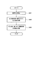
- FIG. 2 is a flowchart showing an example of a schematic operation of the hydrogen generator according to the first embodiment.
- the hydrogen generator 100 generates a hydrogen-containing gas in the reformer 2 and opens the on-off valve 5 so that the hydrogen-containing gas flows through the recycle channel 4 (start).
- the abnormality detector 7 closes the on-off valve 5 (step S101).
- the abnormality detector 7 acquires the pressure value detected by the pressure detector 6 (step S102), and the abnormality detector 7 determines whether or not there is a blockage abnormality in the recycle channel 4 based on the acquired pressure value. (Step S103).
- the abnormality detector 7 determines whether there is a blockage abnormality in the recycle channel 4 based on whether or not the pressure value acquired in step S102 is equal to or greater than the first threshold value. Specifically, when the pressure value is less than the first threshold value, it is determined that a blockage abnormality has occurred in the recycle flow path 4, and when the pressure value is equal to or greater than the first threshold value, It is determined that no blockage abnormality has occurred in the recycle channel 4.
- the first threshold value is set to a value that is higher than the pressure value at the downstream end of the recycle channel 4 and is equal to or lower than the pressure value at the upstream end of the recycle channel 4.
- the first threshold value is less than the minimum value of the pressure value at the upstream end of the recycle channel 4 and the pressure value at the downstream end when the pressure value at the upstream end of the recycle channel 4 shows the minimum value.
- a higher value may be set.
- the first threshold value is not limited to the above, and any pressure value can be set as long as it is possible to determine whether or not there is a blockage abnormality in the recycle flow path 4 upstream from the pressure detector 6. I do not care.
- the abnormality detection is a method of detecting the blockage abnormality of the recycle flow path 4 based on the absolute value of the pressure value detected by the pressure detector 6, and a method of judging from the change width of the pressure value will be described below. To do.
- FIG. 3 is a flowchart showing another example of the schematic operation of the hydrogen generator according to the first embodiment.
- the hydrogen generator 100 generates a hydrogen-containing gas in the reformer 2 and opens the on-off valve 5 so that the hydrogen-containing gas flows through the recycle channel 4 (start).
- the abnormality detector 7 acquires the first pressure value detected by the pressure detector 6 in a state where the on-off valve 5 is open (step S201). Next, the abnormality detector 7 closes the on-off valve 5 (step S202), and acquires the second pressure value detected by the pressure detector 6 (step S203). Then, the abnormality detector 7 detects the presence or absence of a blockage abnormality in the recycle channel 4 based on the pressure difference between the second pressure value acquired in step S203 and the first pressure value acquired in step S201 (step S204). .
- the abnormality detector 7 determines whether or not there is a blockage abnormality in the recycle flow path 4 based on whether or not the pressure difference is equal to or greater than a second threshold value. Specifically, when the pressure difference is less than the second threshold, it is determined that a blockage abnormality has occurred in the recycle flow path 4, and when the pressure difference is equal to or greater than the second threshold, It is determined that no blockage abnormality has occurred in the recycle channel 4.
- the second threshold value is set to a value that is smaller than the pressure loss from the upstream end of the recycle flow path 4 to the pressure detector 6 when the on-off valve 5 is opened, and larger than 0.
- a value that is equal to or less than the minimum value of the pressure loss and greater than 0 may be set.
- the value of the second threshold value is appropriately set depending on how much the recycle flow path 4 is blocked and the blockage is abnormal. For example, when the amount of hydrogen-containing gas flowing through the recycle flow path 4 is more than the amount necessary for hydrodesulfurization and the clogging of the light recycle flow path 4 causes a blockage abnormality, the second threshold value is greater than 0. A value closer to is set. In addition, when the blockage of the severe recycle channel 4 in which the hydrogen-containing gas does not flow through the recycle channel 4 is regarded as a blockage abnormality, a value closer to 0 than the pressure loss is set.
- the second threshold value is not limited to the above, and any value may be set as long as it is possible to detect a blockage abnormality of the recycle flow path 4 upstream of the pressure detector 6.
- the abnormality detector 7 detects the blockage abnormality of the recycle flow path 4 on the upstream side of the pressure detector 6 by closing the on-off valve 5. Can do.
- the abnormality detector 7 has a recycle channel on the downstream side of the pressure detector 6. 4 can be determined to be blocked. For this reason, the abnormality detector 7 can detect a blockage abnormality in the entire recycling channel 4.
- the third threshold value is set to a value higher than the pressure value at the downstream end of the recycle flow path 4 and equal to or lower than the pressure value at the upstream end of the recycle flow path 4.
- a value that is equal to or lower than the minimum pressure value at the upstream end of the recycling flow path 4 and higher than the pressure value at the downstream end when the pressure value at the upstream end of the recycling flow path 4 indicates the minimum value is set. May be. Thereby, the blockage abnormality can be detected regardless of the amount of the raw material supplied from the raw material supplier 3 to the reformer 2.
- the third threshold value is not limited to the above, and any pressure value can be set as long as it is possible to determine whether or not there is a blockage abnormality in the recycle flow path 4 downstream from the pressure detector 6. I do not care.
- the operation of the hydrogen generator 100 may be stopped when the abnormality detector 7 detects a blockage abnormality.
- the abnormality detector 7 detects a blockage abnormality in the recycle channel 4
- the generation of the hydrogen-containing gas in the reformer 2 is interrupted, and after performing a recovery operation to eliminate the blockage, the reforming is performed.
- the generation of the hydrogen-containing gas in the vessel 2 may be resumed.
- the hydrogen generator 100 May be configured to abnormally stop and prohibit activation.
- the on-off valve 5 may be opened and the generation of the hydrogen-containing gas in the reformer 2 may be continued.
- the flow of the hydrogen-containing gas in the recycle channel 4 is forcibly stopped by closing the on-off valve 5, it is preferable that the time for which the on-off valve 5 is closed is short.
- the abnormality detector 7 determines that the abnormality is normal when detecting abnormality (that is, when it is confirmed that the pressure value is equal to or higher than the first threshold)
- the abnormality detector 7 opens and closes before the abnormality determination time expires.
- the valve 5 may be opened.
- the abnormality determination time is a time set for detecting the presence or absence of a blockage abnormality in the recycle flow path 4, and the abnormality detector 7 continuously pressurizes with the pressure detector 6 within this set time. Whether or not there is a blockage abnormality is determined.
- the abnormality detector 7 detects the blockage abnormality because the more the amount of the hydrogen-containing gas generated in the hydrogen generator 100, the easier it is to detect the abnormality in the recycle channel 4. At this time, it may be controlled to increase the amount of hydrogen-containing gas produced.
- the abnormality detector closes the open on-off valve before starting the generation of the hydrogen-containing gas in the reformer, and after closing the on-off valve An occlusion abnormality is detected based on the pressure detected by the pressure detector.
- the blockage abnormality detection may be performed before the temperature raising operation of the reformer, or may be performed during the temperature raising operation of the reformer.
- the blockage abnormality detection before the temperature raising operation may be performed at the initial check for checking whether there is an abnormality in the devices constituting the hydrogen generator.
- the timing of detecting the blockage abnormality is an example, and any timing may be used as long as it is before the start of the production of the hydrogen-containing gas in the reformer.
- the reformer since the reformer detects the blockage abnormality of the recycle flow path before starting the generation of the hydrogen-containing gas, the abnormality detection is performed earlier than the blockage abnormality detection in the hydrogen generator of the first embodiment. Can do.
- the hydrogen generator of the first modification has the same configuration as the hydrogen generator of the first embodiment, the abnormality detection operation of the abnormality detector will be described below.
- FIG. 4 is a flowchart showing an example of a schematic operation of the hydrogen generator in the first modification of the first embodiment.
- the abnormality detector 7 operates the raw material supplier 3 and closes the on-off valve 5 before the reformer 2 starts generating the hydrogen-containing gas (step S301).
- the abnormality detector 7 acquires the pressure value detected by the pressure detector 6 (step S302), and the abnormality detector 7 determines whether there is a blockage abnormality in the recycle channel 4 based on the acquired pressure value. (Step S303).
- the abnormality detector 7 determines whether or not the recycle flow path 4 is blocked depending on whether or not the pressure value acquired in step S302 is equal to or greater than the first threshold value. Determine the presence or absence.
- the abnormality detector 7 employs a form in which the presence / absence of a blockage abnormality in the recycle flow path 4 is determined based on the absolute value of the pressure value.
- the present invention is not limited to this, as in the first embodiment. A form in which the abnormality detector 7 determines based on the change width of the pressure value may be adopted.
- the operation proceeds to the next operation such as the temperature raising operation of the reformer 2 and the generation operation of the hydrogen-containing gas in the reformer 2, for example. Further, if it is confirmed that there is a blockage abnormality, for example, the hydrogen generator does not shift to the next operation such as the temperature raising operation of the reformer 2 and the hydrogen-containing gas generating operation in the reformer 2. 100 operations may be stopped.
- the abnormality detector 7 may control the raw material supplier 3 so as to push the raw material into the upstream side of the recycle flow path 4 at a predetermined pressure or higher. Thereby, the detection accuracy of the blockage abnormality can be improved.
- the state in which the reformer has stopped generating the hydrogen-containing gas means a state in which supply of at least one of the raw material and water to the reformer is stopped.
- the hydrogen generator of the second modification has the same configuration as that of the hydrogen generator of the first embodiment, the abnormality detection operation of the abnormality detector will be described below.
- FIG. 5 is a flowchart showing an example of a schematic operation of the hydrogen generator according to the second modified example of the first embodiment.
- the abnormality detector 7 closes the on-off valve 5 after the reformer 2 stops generating the hydrogen-containing gas (step S401).
- the abnormality detector 7 acquires the pressure value detected by the pressure detector 6 (step S402), and the abnormality detector 7 determines whether there is a blockage abnormality in the recycle channel 4 based on the acquired pressure value. (Step S403).
- the abnormality detector 7 determines whether or not the recycling flow path 4 is blocked depending on whether or not the pressure value acquired in step S402 is equal to or greater than the first threshold value. Determine the presence or absence.
- the abnormality detector 7 employs a form in which the presence or absence of a blockage abnormality in the recycle flow path 4 is determined based on the absolute value of the pressure value.
- the present invention is not limited to this, and as described above, the abnormality detector 7 may adopt a form in which the determination is made based on the change width of the pressure value.
- the hydrogen generator of the second embodiment includes a throttle portion provided in the recycle channel in the hydrogen generator of any one of the first embodiment and the modifications thereof, and the pressure detector is provided downstream of the throttle portion. Is provided.
- the hydrogen generator of the second embodiment may be configured in the same manner as the hydrogen generator of any one of the first embodiment and the modified example of the first embodiment except for the above features.
- FIG. 6 is a conceptual diagram showing an example of a schematic configuration of the hydrogen generator according to the second embodiment.
- the hydrogen generator 100 of the second embodiment includes a hydrodesulfurizer 1, a reformer 2, a raw material supplier 3, a recycle channel 4, an on-off valve 5, and pressure detection.
- the throttle unit 8 is provided in the recycle channel 4.
- the throttle unit 8 is configured to adjust the flow rate of the hydrogen-containing gas flowing through the recycle flow path 4 by making the flow path cross-sectional area smaller than the recycle flow path 4 before and after that.
- the restricting portion 8 may have any configuration as long as it is configured to have a channel cross-sectional area smaller than that of the recycling channel 4 before and after that.
- the throttle portion 8 may be configured by a pipe that is narrower than the pipe that configures the recycle channel 4, or may be configured by a plate member that has a hole that is narrower than the pipe that configures the recycle channel 4. Good.
- the pressure (in the recycle channel 4 upstream of the throttle unit 8 is equal to the upstream end of the recycle channel 4 ( Hereinafter, the pressure before the throttle portion is applied.
- the same pressure as the downstream end of the recycle channel 4 hereinafter, the throttle unit rear pressure
- the flow rate of the hydrogen-containing gas flowing through the throttle 8 is determined by the differential pressure between the pressure before the throttle and the pressure after the throttle.
- the pressure after the throttle unit 8 and the pressure before the throttle unit 8 are the same pressure.
- the flow of the hydrogen-containing gas at the throttle portion 8 stops.
- the pressure detected by the pressure detector 6 was close to the pressure value at the downstream end of the recycle channel 4 before the abnormality detection operation, whereas the pressure value at the upstream end of the recycle channel 4 was Rise to a close value.
- the abnormality detector 7 it is confirmed by the abnormality detector 7 that the pressure detected by the pressure detector 6 is equal to or higher than the first threshold value, and it is determined that there is no occlusion abnormality.
- the throttle unit 8 when the throttle unit 8 is closed, even if the abnormality detector 7 closes the on-off valve 5 to detect an abnormality, the pressure after the throttle unit 8 does not increase, and the downstream side of the recycling flow path 4. A value close to the end pressure value is maintained. Thereby, it is confirmed by the abnormality detector 7 that the pressure detected by the pressure detector 6 is less than the first threshold value, and it is determined that a blockage abnormality has occurred.
- the hydrogen generation device according to the third embodiment is the hydrogen generation device according to any one of the first embodiment, the modifications thereof, and the second embodiment, and includes a buffer unit in a recycle channel downstream of the on-off valve.
- the on-off valve is closed so that the hydrogen-containing gas is supplied to the hydrodesulfurization unit even if the hydrogen-containing gas temporarily does not flow through the recycle flow path. It is possible to prevent the hydrogen concentration in the mixed gas of the raw material and the recycle gas from becoming a predetermined concentration or less.
- the hydrogen generator of the present embodiment may be configured in the same manner as the hydrogen generator of any one of the first embodiment, the modified example of the first embodiment, and the second embodiment, except for the above characteristics.
- FIG. 7 is a conceptual diagram illustrating an example of a schematic configuration of a hydrogen generator according to the third embodiment.
- the hydrogen generator 100 of the third embodiment includes a hydrodesulfurizer 1, a reformer 2, a raw material supplier 3, a recycle channel 4, an on-off valve 5, and pressure detection.
- the buffer unit 9 is provided in the recycle channel 4.
- the buffer unit 9 is installed on the downstream side of the on-off valve 5 with respect to the flow of the hydrogen-containing gas flowing through the recycle channel 4. This buffer unit 9 makes it possible to continue supplying the hydrogen-containing gas to the hydrodesulfurizer 1 while the on-off valve 5 is closed and the hydrogen-containing gas does not flow through the recycle channel 4.
- the buffer unit 9 may have any configuration as long as it can hold the hydrogen-containing gas for the time during which the on-off valve 5 is closed, as long as it has a tank shape or a long pipe.
- the hydrogen-containing gas that can be supplied to the hydrodesulfurizer 1 while the on-off valve 5 is open is stored in the buffer unit 9. Even if the on-off valve 5 is closed by the stored hydrogen-containing gas, the supply of the hydrogen-containing gas to the hydrodesulfurizer 1 is continued, so that the hydrodesulfurizer 1 is deteriorated or the reformer downstream. 2 can be prevented from deteriorating. It is considered that the supply of the hydrogen-containing gas stored in the buffer unit 9 to the hydrodesulfurizer 1 is caused by diffusion.
- the volume of the buffer unit 9 is determined by the time for closing the on-off valve 5 and the amount of hydrogen required for the hydrodesulfurizer 1. Further, a throttle part such as a fixed orifice may be provided on the downstream side of the buffer part 9 of the recycle channel 4. Thereby, the pressure difference between the pressure of the buffer unit 9 and the downstream end of the recycle channel 4 is generated, and the hydrogen-containing gas stored in the buffer unit 9 can be easily supplied by the hydrodesulfurizer 1.
- the hydrogen generation device is the hydrogen generation device according to any one of the first embodiment, the modifications thereof, the second embodiment, and the third embodiment, in which the abnormality detector blocks the recycle channel.
- a controller that executes a process for eliminating the blockage of the recycling flow path is provided.
- the hydrogen generator of the present embodiment is configured in the same manner as the hydrogen generator of any of the first embodiment, the modified example of the first embodiment, the second embodiment, and the third embodiment except for the above features. May be.
- FIG. 8 is a conceptual diagram showing an example of a schematic configuration of the hydrogen generator according to the fourth embodiment.
- the hydrogen generator 100 of the fourth embodiment includes a hydrodesulfurizer 1, a reformer 2, a raw material supplier 3, a recycle channel 4, an on-off valve 5, and pressure detection.
- a device 6, an abnormality detector 7, and a controller 11 are provided.
- the controller 11 executes a process for eliminating the blockage of the recycle channel 4.
- the controller 11 only needs to control equipment (for example, the raw material supplier 3) that needs to be operated when executing the process of eliminating the blockage abnormality of the recycle flow path 4, and includes an arithmetic processing unit and a control program. Is provided with a storage unit (none of which is shown).
- the MPU and CPU are exemplified as the arithmetic processing unit.
- An example of the storage unit is a memory.
- the controller 11 may be composed of a single controller that performs centralized control, or may be composed of a plurality of controllers that perform distributed control in cooperation with each other.
- the controller 11 may also serve as the abnormality detector 7.
- the controller 11 executes a process for eliminating the blockage of the recycle channel 4. Specifically, the controller 11 controls the hydrogen generator 100 so as to increase the output (hydrogen generation amount) in the reformer 2. More specifically, the controller 11 controls the raw material supplier 3 to increase the flow rate of the raw material supplied to the reformer 2.
- the hydrogen generator of the first modified example in the fourth embodiment includes a notification device that notifies that a process for eliminating the blockage of the recycle flow path is being executed.
- FIG. 9 is a conceptual diagram illustrating an example of a schematic configuration of a hydrogen generator according to a first modified example of the fourth embodiment.
- the hydrogen generator 100 of the first modified example in the fourth embodiment includes a hydrodesulfurizer 1, a reformer 2, a raw material supplier 3, a recycle channel 4, and an on-off valve. 5, a pressure detector 6, an abnormality detector 7, a controller 11, and a notification device 12.
- the notification device 12 may have any configuration as long as it can notify the outside that the process of eliminating the blockage of the recycling flow path 4 is being performed.
- a mode for informing outside for example, a mode in which character data or image data or the like is displayed on a display unit (screen) of a remote controller, a mode in which a speaker or the like is used for voice notification, light or color may be used. It may be a mode that informs by.
- the aspect notified to a smart phone, a mobile telephone, or a tablet-type computer etc. with an email or an application via a communication network may be sufficient.
- the controller 11 executes a process for eliminating the blockage of the recycle channel 4. Then, when the controller 11 executes a process for eliminating the blockage of the recycle channel 4, the notification device 12 notifies the outside that the process for eliminating the blockage of the recycle channel 4 is being performed.
- the object to be notified is a user
- even if the user feels that the operation of the hydrogen generation apparatus 100 is abnormal it is possible to notify the fact that the process is being executed, thereby generating hydrogen. It is possible to notify the user or the like whether the operation of the apparatus 100 is abnormal, and it is possible to remove the user's anxiety.
- the hydrogen generator of 5th Embodiment is the hydrogen generator of any one of 1st Embodiment, those modifications, 2nd Embodiment, 3rd Embodiment, 4th Embodiment, and the modification of 4th Embodiment. And it is provided with the alerting device which alert
- the hydrogen generator of the present embodiment is the same as the first embodiment, the modification of the first embodiment, the second embodiment, the third embodiment, the fourth embodiment, and the modification of the fourth embodiment except for the above features. You may comprise similarly to the hydrogen generator of any of an example.
- the alarm of the hydrogen generator of the modification of 4th Embodiment and the alarm of this embodiment may be comprised with the same apparatus, and may be comprised with a different apparatus.
- FIG. 10 is a conceptual diagram showing an example of a schematic configuration of a hydrogen generator according to the fifth embodiment.
- the hydrogen generator 100 of the fifth embodiment includes a hydrodesulfurizer 1, a reformer 2, a raw material supplier 3, a recycle channel 4, an on-off valve 5, and pressure detection.
- a device 6, an abnormality detector 7, and a notification device 12 are provided.
- the alarm 12 may have any configuration as long as it can notify the outside that an abnormality has occurred in the hydrogen generator 100 (a blockage abnormality has occurred in the recycle channel 4).
- a mode for informing outside for example, a mode in which character data or image data or the like is displayed on a display unit (screen) of a remote controller, a mode in which a speaker or the like is used for voice notification, light or color may be used. It may be a mode that informs by.
- the aspect notified to a smart phone, a mobile telephone, or a tablet-type computer etc. with an email or an application via a communication network may be sufficient.
- the alarm device 12 When the abnormality detector 7 detects a blockage abnormality in the recycle flow path 4, the alarm device 12 indicates that an abnormality has occurred in the hydrogen generator 100 (a blockage abnormality has occurred in the recycle flow path 4). To inform.
- the user's anxiety about why the hydrogen generator 100 is not operating can be removed.
- the maintenance worker rushes early from the occurrence of the abnormality and repairs the hydrogen generator 100, so that the hydrogen generator 100 can resume its operation at an early stage.
- the fuel cell system according to the sixth embodiment includes any one of the first embodiment, modifications thereof, the second embodiment, the third embodiment, the fourth embodiment, the modification of the fourth embodiment, and the fifth embodiment. And a fuel cell that generates electric power using a hydrogen-containing gas supplied from the hydrogen generator.
- FIG. 11 is a conceptual diagram showing an example of a schematic configuration of a fuel cell system according to the sixth embodiment.
- the fuel cell system 200 of the sixth embodiment includes the hydrogen generator 100 of the first embodiment and the fuel cell 10.
- the fuel cell 10 is a fuel cell that generates power using the hydrogen-containing gas supplied from the hydrogen generator 100.
- the fuel cell 10 may be any type of fuel cell.
- a polymer electrolyte fuel cell (PEFC), a solid oxide fuel cell, or a phosphoric acid fuel cell may be used.
- the fuel cell system 200 During the power generation operation, the fuel cell system 200 generates power using the hydrogen-containing gas supplied from the hydrogen generator 100.
- the operation of the hydrogen generator 100 in the present embodiment is the same as that in the first embodiment when the fuel cell 10 is considered as a hydrogen-using device in the first embodiment. Therefore, detailed description is omitted.
- the hydrogen generation apparatus, the operation method of the hydrogen generation apparatus, and the fuel cell system of the present invention can detect the blockage abnormality of the recycle flow path more easily than before.
Landscapes
- Chemical & Material Sciences (AREA)
- Chemical Kinetics & Catalysis (AREA)
- Engineering & Computer Science (AREA)
- General Chemical & Material Sciences (AREA)
- Sustainable Energy (AREA)
- Sustainable Development (AREA)
- Manufacturing & Machinery (AREA)
- Electrochemistry (AREA)
- Life Sciences & Earth Sciences (AREA)
- Organic Chemistry (AREA)
- Health & Medical Sciences (AREA)
- General Health & Medical Sciences (AREA)
- Combustion & Propulsion (AREA)
- Inorganic Chemistry (AREA)
- Hydrogen, Water And Hydrids (AREA)
- Fuel Cell (AREA)
Abstract
Description
第1実施形態に係る水素生成装置は、原料中の硫黄化合物を除去する水添脱硫器と、水添脱硫器を通過した原料を用いて水素含有ガスを生成する改質器と、改質器に原料を供給する原料供給器と、改質器より排出された水素含有ガスの一部を水添脱硫器に流入する前の原料に供給するためのリサイクル流路と、リサイクル流路に設けられた開閉弁と、開閉弁よりも上流のリサイクル流路に設けられた圧力検知器と、開閉弁を閉じた状態で、原料供給器により改質器に原料を供給しているときの圧力検知器により検知された圧力に基づきリサイクル流路の閉塞異常を検知する異常検知器と、を備える。
図1は、第1実施形態に係る水素生成装置の概略構成の一例を示す概念図である。
以下、水素生成装置100の動作について、図2及び図3を参照しながら説明する。なお、以下では、水素生成装置100の水素生成動作は、公知の水素生成装置と同様に行われるため、その詳細な説明は省略し、リサイクル流路4の閉塞異常を検知する動作について説明する。
次に、第1実施形態の水素生成装置100の変形例について説明する。
第1実施形態における第2変形例の水素生成装置は、異常検知器が、改質器で水素含有ガスの生成を停止した後に、開放している開閉弁を閉じるとともに、開閉弁を閉止後の圧力検知器により検出された圧力に基づき、閉塞異常を検知するように構成されている。
第2実施形態の水素生成装置は、第1実施形態及びそれらの変形例のいずれかの水素生成装置において、リサイクル流路に設けられた絞り部を備え、圧力検知器は、絞り部の下流に設けられている。
図6は、第2実施形態に係る水素生成装置の概略構成の一例を示す概念図である。
以下、第2水素生成装置100の動作の一例について説明する。
第3実施形態の水素生成装置は、第1実施形態、それらの変形例、及び第2実施形態のいずれかの水素生成装置であって、開閉弁の下流のリサイクル流路にバッファ部を備える。
図7は、第3実施形態に係る水素生成装置の概略構成の一例を示す概念図である。
以下、第3実施形態の水素生成装置100の動作の一例について説明する。
第4実施形態の水素生成装置は、第1実施形態、それらの変形例、第2実施形態、及び第3実施形態のいずれかの水素生成装置であって、異常検知器がリサイクル流路の閉塞異常を検知すると、リサイクル流路の閉塞を解消する処理を実行する制御器を備える。
図8は、第4実施形態に係る水素生成装置の概略構成の一例を示す概念図である。
以下、第4実施形態の水素生成装置100の動作の一例について説明する。
次に、第4実施形態の水素生成装置の変形例について説明する。
図9は、第4実施形態における第1変形例の水素生成装置の概略構成の一例を示す概念図である。
以下、第4実施形態における第1変形例の水素生成装置100の動作の一例について説明する。
第5実施形態の水素生成装置は、第1実施形態、それらの変形例、第2実施形態、第3実施形態、第4実施形態、及び第4実施形態の変形例のいずれかの水素生成装置であって、リサイクル流路で閉塞異常が発生していることを報知する報知器を備える。
図10は、第5実施形態に係る水素生成装置の概略構成の一例を示す概念図である。
以下、第5実施形態の水素生成装置100の動作の一例について説明する。
第6実施形態の燃料電池システムは、第1実施形態、それらの変形例、第2実施形態、第3実施形態、第4実施形態、第4実施形態の変形例、及び第5実施形態のいずれかの水素生成装置と、水素生成装置より供給される水素含有ガスを用いて発電する燃料電池と、を備える。
2 改質器
3 原料供給器
4 リサイクル流路
5 開閉弁
6 圧力検知器
7 異常検知器
8 絞り部
9 バッファ部
10 燃料電池
11 制御器
12 報知器
100 水素生成装置
200 燃料電池システム
Claims (11)
- 原料中の硫黄化合物を除去する水添脱硫器と、
前記水添脱硫器を通過した原料を用いて水素含有ガスを生成する改質器と、
前記改質器に原料を供給する原料供給器と、
前記改質器より排出された水素含有ガスの一部を前記水添脱硫器に流入する前の原料に供給するためのリサイクル流路と、
前記リサイクル流路に設けられた開閉弁と、
前記開閉弁よりも上流のリサイクル流路に設けられた圧力検知器と、
前記開閉弁を閉じた状態で、前記原料供給器により前記改質器に原料を供給しているときの前記圧力検知器により検知された圧力に基づき前記リサイクル流路の閉塞異常を検知する異常検知器と、を備える、水素生成装置。 - 前記異常検知器は、前記改質器で水素含有ガスの生成を行っているときに、開放している前記開閉弁を閉じるとともに、前記開閉弁を閉止後の前記圧力検知器により検出された圧力に基づき閉塞異常を検知する、請求項1記載の水素生成装置。
- 前記異常検知器は、前記改質器で水素含有ガスの生成を開始する前に、開放している前記開閉弁を閉じるとともに、前記開閉弁を閉止後の前記圧力検知器により検出された圧力に基づき閉塞異常を検知する、請求項1記載の水素生成装置。
- 前記異常検知器は、前記改質器で水素含有ガスの生成を停止した後に、開放している前記開閉弁を閉じるとともに、前記開閉弁を閉止後の前記圧力検知器により検出された圧力に基づき閉塞異常を検知する、請求項1記載の水素生成装置。
- 前記リサイクル流路に設けられた絞り部を備え、前記圧力検知器は、前記絞り部の下流に設けられている、請求項1~4のいずれかに記載の水素生成装置。
- 前記開閉弁の下流のリサイクル流路にバッファ部を備える、請求項1~5のいずれかに記載の水素生成装置。
- 前記異常検知器が前記リサイクル流路の閉塞異常を検知すると、前記リサイクル流路の閉塞を解消する処理を実行する制御器を備える、請求項1~6のいずれかに記載する水素生成装置。
- 前記リサイクル流路で閉塞異常が発生していることを報知する報知器を備える、請求項1~7のいずれかに記載する水素生成装置。
- 前記リサイクル流路の閉塞を解消する処理を実行していることを報知する報知器を備える、請求項7又は8に記載の水素生成装置。
- 請求項1~9のいずれかに記載の水素生成装置と、
前記水素生成装置より供給される水素含有ガスを用いて発電する燃料電池と、を備える、燃料電池システム。 - 水素生成装置の運転方法であって、
水添脱硫器で原料中の硫黄化合物を除去するステップと、
前記水添脱硫器を通過した原料を用いて改質器で水素含有ガスを生成するステップと、
リサイクル流路を介して前記改質器より排出された水素含有ガスの一部を前記水添脱硫器に流入する前の原料に供給するステップと、
圧力検知器で前記リサイクル流路に設けられた開閉弁よりも上流のリサイクル流路の圧力を検知するステップと、
前記開閉弁を閉じた状態で、前記改質器に原料を供給しているときに、前記圧力検知器により検知された圧力に基づき前記リサイクル流路の閉塞異常を検知するステップと、を備える、水素生成装置の運転方法。
Priority Applications (3)
| Application Number | Priority Date | Filing Date | Title |
|---|---|---|---|
| EP12842310.0A EP2769958B1 (en) | 2011-10-20 | 2012-10-03 | Method for operating a hydrogen generation apparatus |
| US13/989,325 US9070915B2 (en) | 2011-10-20 | 2012-10-03 | Hydrogen generator, operating method of hydrogen generator, and fuel cell system |
| JP2013506384A JP5914863B2 (ja) | 2011-10-20 | 2012-10-03 | 水素生成装置、水素生成装置の運転方法、及び燃料電池システム |
Applications Claiming Priority (2)
| Application Number | Priority Date | Filing Date | Title |
|---|---|---|---|
| JP2011-231044 | 2011-10-20 | ||
| JP2011231044 | 2011-10-20 |
Publications (1)
| Publication Number | Publication Date |
|---|---|
| WO2013057891A1 true WO2013057891A1 (ja) | 2013-04-25 |
Family
ID=48140560
Family Applications (1)
| Application Number | Title | Priority Date | Filing Date |
|---|---|---|---|
| PCT/JP2012/006361 Ceased WO2013057891A1 (ja) | 2011-10-20 | 2012-10-03 | 水素生成装置、水素生成装置の運転方法、及び燃料電池システム |
Country Status (4)
| Country | Link |
|---|---|
| US (1) | US9070915B2 (ja) |
| EP (1) | EP2769958B1 (ja) |
| JP (1) | JP5914863B2 (ja) |
| WO (1) | WO2013057891A1 (ja) |
Cited By (4)
| Publication number | Priority date | Publication date | Assignee | Title |
|---|---|---|---|---|
| WO2014097622A1 (ja) * | 2012-12-19 | 2014-06-26 | パナソニック株式会社 | 燃料電池システムおよび燃料電池システムの運転方法 |
| WO2015044986A1 (ja) * | 2013-09-30 | 2015-04-02 | パナソニックIpマネジメント株式会社 | 水素発生装置およびその運転方法 |
| WO2015125450A1 (ja) * | 2014-02-18 | 2015-08-27 | パナソニック株式会社 | 燃料電池システム |
| JP2019186109A (ja) * | 2018-04-13 | 2019-10-24 | アイシン精機株式会社 | 燃料電池システム |
Families Citing this family (2)
| Publication number | Priority date | Publication date | Assignee | Title |
|---|---|---|---|---|
| JP6290730B2 (ja) * | 2014-06-30 | 2018-03-07 | アイシン精機株式会社 | 燃料電池システム |
| JPWO2016021182A1 (ja) * | 2014-08-04 | 2017-05-25 | パナソニックIpマネジメント株式会社 | 水素生成装置およびその運転方法ならびに燃料電池システム |
Citations (4)
| Publication number | Priority date | Publication date | Assignee | Title |
|---|---|---|---|---|
| JPH1092452A (ja) | 1996-09-17 | 1998-04-10 | Fuji Electric Co Ltd | 燃料電池発電装置の異常検知方法 |
| JP2003236393A (ja) * | 2002-02-18 | 2003-08-26 | Osaka Gas Co Ltd | 触媒還元方法 |
| JP2006104003A (ja) * | 2004-10-04 | 2006-04-20 | Fuji Electric Holdings Co Ltd | 燃料改質システム |
| JP2011195391A (ja) * | 2010-03-19 | 2011-10-06 | Osaka Gas Co Ltd | 水素含有ガス生成装置の起動時運転方法 |
Family Cites Families (9)
| Publication number | Priority date | Publication date | Assignee | Title |
|---|---|---|---|---|
| US4098960A (en) * | 1976-12-27 | 1978-07-04 | United Technologies Corporation | Fuel cell fuel control system |
| US5686196A (en) | 1996-10-09 | 1997-11-11 | Westinghouse Electric Corporation | System for operating solid oxide fuel cell generator on diesel fuel |
| US6630109B2 (en) * | 1998-07-16 | 2003-10-07 | Toyota Jidosha Kabushiki Kaisha | Control apparatus for reformer and method of controlling reformer using control apparatus |
| US6733552B1 (en) * | 1999-03-15 | 2004-05-11 | Matsushita Electric Industrial Co., Ltd. | Hydrogen generating apparatus |
| US20050208357A1 (en) * | 2004-03-16 | 2005-09-22 | Bitzer Alan S | Fuel cell hybrid pump-ejector fuel recycle system |
| JP4751608B2 (ja) | 2004-12-24 | 2011-08-17 | アイシン精機株式会社 | カソード用ポンプまたはブロアの制御装置、および燃料電池システム |
| JP4991165B2 (ja) * | 2006-02-27 | 2012-08-01 | アイシン精機株式会社 | 燃料電池システム |
| KR20110016432A (ko) | 2008-05-22 | 2011-02-17 | 유티씨 파워 코포레이션 | 처리기 원료 가압 장치의 상류에 적용되는 수력 탈황기 재순환 |
| CN102395523B (zh) * | 2009-12-25 | 2015-04-22 | 松下电器产业株式会社 | 氢生成装置和燃料电池系统 |
-
2012
- 2012-10-03 WO PCT/JP2012/006361 patent/WO2013057891A1/ja not_active Ceased
- 2012-10-03 US US13/989,325 patent/US9070915B2/en not_active Expired - Fee Related
- 2012-10-03 JP JP2013506384A patent/JP5914863B2/ja not_active Expired - Fee Related
- 2012-10-03 EP EP12842310.0A patent/EP2769958B1/en not_active Not-in-force
Patent Citations (4)
| Publication number | Priority date | Publication date | Assignee | Title |
|---|---|---|---|---|
| JPH1092452A (ja) | 1996-09-17 | 1998-04-10 | Fuji Electric Co Ltd | 燃料電池発電装置の異常検知方法 |
| JP2003236393A (ja) * | 2002-02-18 | 2003-08-26 | Osaka Gas Co Ltd | 触媒還元方法 |
| JP2006104003A (ja) * | 2004-10-04 | 2006-04-20 | Fuji Electric Holdings Co Ltd | 燃料改質システム |
| JP2011195391A (ja) * | 2010-03-19 | 2011-10-06 | Osaka Gas Co Ltd | 水素含有ガス生成装置の起動時運転方法 |
Cited By (6)
| Publication number | Priority date | Publication date | Assignee | Title |
|---|---|---|---|---|
| WO2014097622A1 (ja) * | 2012-12-19 | 2014-06-26 | パナソニック株式会社 | 燃料電池システムおよび燃料電池システムの運転方法 |
| WO2015044986A1 (ja) * | 2013-09-30 | 2015-04-02 | パナソニックIpマネジメント株式会社 | 水素発生装置およびその運転方法 |
| WO2015125450A1 (ja) * | 2014-02-18 | 2015-08-27 | パナソニック株式会社 | 燃料電池システム |
| JP5886485B2 (ja) * | 2014-02-18 | 2016-03-16 | パナソニック株式会社 | 燃料電池システム |
| US10014536B2 (en) | 2014-02-18 | 2018-07-03 | Panasonic Corporation | Fuel cell system |
| JP2019186109A (ja) * | 2018-04-13 | 2019-10-24 | アイシン精機株式会社 | 燃料電池システム |
Also Published As
| Publication number | Publication date |
|---|---|
| JPWO2013057891A1 (ja) | 2015-04-02 |
| US20140057185A1 (en) | 2014-02-27 |
| US9070915B2 (en) | 2015-06-30 |
| JP5914863B2 (ja) | 2016-05-11 |
| EP2769958A4 (en) | 2014-12-24 |
| EP2769958B1 (en) | 2018-12-19 |
| EP2769958A1 (en) | 2014-08-27 |
Similar Documents
| Publication | Publication Date | Title |
|---|---|---|
| JP5914863B2 (ja) | 水素生成装置、水素生成装置の運転方法、及び燃料電池システム | |
| US6811908B2 (en) | System and method for controlling the operation of a fuel processing system | |
| KR100827954B1 (ko) | 용융탄산염 연료전지 보호 장치 및 그 방법 | |
| JPWO2008035776A1 (ja) | 水素生成装置、水素生成装置の運転方法、及び燃料電池システム | |
| US9685672B2 (en) | Hydrogen generation apparatus, fuel cell system including the same, method of operating hydrogen generation apparatus and method of operating fuel cell system | |
| WO2012169199A1 (ja) | 水素発生装置、これを備える燃料電池システム、及び水素発生装置の運転方法 | |
| JP2016104686A (ja) | 水素生成装置および燃料電池システム | |
| JP5938557B2 (ja) | 水素発生装置 | |
| JP2012250876A (ja) | 水素生成装置及び燃料電池システム | |
| EP3178784B1 (en) | Hydrogen generation apparatus, operation method thereof, and fuel cell system | |
| JP6319555B2 (ja) | 水素生成装置及び燃料電池システム及び水素生成装置の運転方法 | |
| WO2014097622A1 (ja) | 燃料電池システムおよび燃料電池システムの運転方法 | |
| KR102018116B1 (ko) | 연료전지 비상 차단 시스템 및 그 방법 | |
| JP2016167382A (ja) | 燃料電池システムおよびその運転方法 | |
| JP2014101264A (ja) | 水素生成装置の運転方法及び燃料電池システムの運転方法 | |
| JP2017154094A (ja) | 脱硫システムと、それを備えた水素生成装置と、それを備えた燃料電池システムと、それらの運転方法 | |
| US20140023944A1 (en) | Fuel cell system and method of operating same | |
| JP2005098318A (ja) | 液化石油ガスの供給方法および装置ならびに液化石油ガス貯蔵手段の交換方法 | |
| JP2015151327A (ja) | 水素生成装置、水素生成装置の運転方法、及び燃料電池システム | |
| EP2980902A1 (en) | Hydrogen generating device, fuel cell system provided with same, method for operating hydrogen generating device, and method for operating fuel cell system | |
| JP5874041B2 (ja) | 燃料電池システム及び燃料電池システムの運転方法 | |
| JP6770268B2 (ja) | 燃料電池セルの保護装置、燃料電池、燃料電池セルの駆動方法 | |
| JP6268980B2 (ja) | 燃料電池システム | |
| JP2014125387A (ja) | 水素生成装置、燃料電池システム、水素生成装置の運転方法及び燃料電池システムの運転方法 | |
| WO2015044986A1 (ja) | 水素発生装置およびその運転方法 |
Legal Events
| Date | Code | Title | Description |
|---|---|---|---|
| ENP | Entry into the national phase |
Ref document number: 2013506384 Country of ref document: JP Kind code of ref document: A |
|
| WWE | Wipo information: entry into national phase |
Ref document number: 2012842310 Country of ref document: EP |
|
| WWE | Wipo information: entry into national phase |
Ref document number: 13989325 Country of ref document: US |
|
| 121 | Ep: the epo has been informed by wipo that ep was designated in this application |
Ref document number: 12842310 Country of ref document: EP Kind code of ref document: A1 |
|
| NENP | Non-entry into the national phase |
Ref country code: DE |