WO2013058111A1 - Lentille de capture d'image - Google Patents
Lentille de capture d'image Download PDFInfo
- Publication number
- WO2013058111A1 WO2013058111A1 PCT/JP2012/075631 JP2012075631W WO2013058111A1 WO 2013058111 A1 WO2013058111 A1 WO 2013058111A1 JP 2012075631 W JP2012075631 W JP 2012075631W WO 2013058111 A1 WO2013058111 A1 WO 2013058111A1
- Authority
- WO
- WIPO (PCT)
- Prior art keywords
- lens
- imaging
- positive
- image
- focal length
- Prior art date
- Legal status (The legal status is an assumption and is not a legal conclusion. Google has not performed a legal analysis and makes no representation as to the accuracy of the status listed.)
- Ceased
Links
Images


Classifications
-
- G—PHYSICS
- G02—OPTICS
- G02B—OPTICAL ELEMENTS, SYSTEMS OR APPARATUS
- G02B13/00—Optical objectives specially designed for the purposes specified below
- G02B13/001—Miniaturised objectives for electronic devices, e.g. portable telephones, webcams, PDAs, small digital cameras
- G02B13/0015—Miniaturised objectives for electronic devices, e.g. portable telephones, webcams, PDAs, small digital cameras characterised by the lens design
- G02B13/002—Miniaturised objectives for electronic devices, e.g. portable telephones, webcams, PDAs, small digital cameras characterised by the lens design having at least one aspherical surface
- G02B13/0045—Miniaturised objectives for electronic devices, e.g. portable telephones, webcams, PDAs, small digital cameras characterised by the lens design having at least one aspherical surface having five or more lenses
Definitions
- the present invention relates to an imaging lens. More specifically, an imaging optical device that captures an image of a subject with an imaging device (for example, a solid-state imaging device such as a CCD (Charge Coupled Device) type image sensor, a CMOS (Complementary Metal-Oxide Semiconductor) type image sensor), and the like are mounted.
- an imaging device for example, a solid-state imaging device such as a CCD (Charge Coupled Device) type image sensor, a CMOS (Complementary Metal-Oxide Semiconductor) type image sensor), and the like are mounted.
- the present invention relates to a digital apparatus with an image input function and a small imaging lens that forms an optical image of a subject on a light receiving surface of an imaging element.
- imaging optical devices using a solid-state imaging device such as a CCD type image sensor or a CMOS type image sensor have been mounted on mobile terminals, and with the widespread use of the mobile terminals, higher quality images have been obtained.
- a device equipped with an image pickup optical device using an image pickup device having a high number of pixels has been supplied to the market.
- the image pickup device having the high number of pixels has been accompanied by an increase in size
- an increase in the size of pixels has progressed, and the image pickup device has been reduced in size.
- An imaging lens used in such a highly thinned image sensor is required to have a high resolving power in order to cope with a highly thinned pixel.
- the resolving power of the lens is limited by the F value, and a bright lens with a small F value can obtain a high resolving power, so that a sufficient performance cannot be obtained with an F value of about F2.8 as in the past. Yes. Accordingly, there has been a demand for a bright imaging lens of about F2, which is suitable for an imaging device with a high pixel size, a high resolution, and a small size.
- an imaging lens for such an application an imaging lens having a five-lens configuration has been proposed because a large aperture ratio and high performance can be achieved as compared with a lens having three or four lenses.
- the five-lens imaging lens includes, in order from the object side, a front lens group, an aperture stop, and a rear lens group.
- the front lens has a first lens having a positive or negative refractive power and a second lens having a positive refractive power.
- an imaging lens in which the rear group includes a third lens having a negative refractive power, a fourth lens having a positive refractive power, and a fifth lens having a negative or positive refractive power.
- Patent Document 2 discloses an imaging lens that includes a third lens having a negative refractive power and a fourth lens having a positive refractive power.
- the imaging lens described in Patent Document 1 has a front lens group that is composed of a spherical system, if it is brightened to about F2, correction of spherical aberration and coma becomes insufficient, and good performance cannot be ensured.
- the front group and the rear group have a positive refracting power, the principal point of the optical system is on the image side and the back side compared to a telephoto type structure in which the rear group has a negative refracting power. The focus becomes longer. For this reason, it is a disadvantageous type for downsizing.
- the imaging lens described in Patent Document 2 has a brightness of about F2, but the first lens and the second lens arranged on the object side of the aperture stop have a positive refractive power. For this reason, the color correction in the front group is insufficient. Further, like the one described in Patent Document 1, both the front group and the rear group have a positive refractive power, and the final lens is also a positive lens, which is disadvantageous for downsizing.
- the imaging lens described in Patent Document 3 has a brightness of about F2, the aberration correction is insufficient because of the four-lens configuration. Therefore, it cannot be said that the imaging lens is suitable for increasing the number of pixels.
- the present invention has been made in view of such problems, and an object of the present invention is to capture a bright five-lens structure of about F2.0 in which various aberrations are well corrected while being smaller than the conventional type. To provide a lens.
- an imaging lens of a first invention is an imaging lens for forming a subject image on an imaging surface of an imaging element, and in order from the object side, a positive first lens and an aperture It consists of a stop, a positive second lens, a negative third lens, a positive fourth lens, and a negative fifth lens, and satisfies the following conditional expression (1). 0 ⁇ f1 / f2 ⁇ 1.26 (1) However, f1: focal length of the first lens, f2: focal length of the second lens, It is.
- An imaging lens of a second invention is an imaging lens for forming a subject image on an imaging surface of an imaging element, and in order from the object side, a positive first lens, a positive second lens, and a negative It consists of a third lens, a positive fourth lens, and a negative fifth lens, and satisfies the following conditional expression (2). -4.0 ⁇ f3 / f ⁇ -1.1 (2) However, f3: focal length of the third lens, f: focal length of the entire imaging lens system, It is.
- An imaging lens of a third invention is an imaging lens for forming a subject image on an imaging surface of an imaging element, and in order from the object side, a positive first lens, an aperture stop, and a positive second lens. And a negative third lens, a positive fourth lens, and a negative fifth lens, which satisfy the following conditional expressions (1) and (2). 0 ⁇ f1 / f2 ⁇ 1.26 (1) -4.0 ⁇ f3 / f ⁇ -1.1 (2) However, f1: focal length of the first lens, f2: focal length of the second lens, f3: focal length of the third lens, f: focal length of the entire imaging lens system, It is.
- the first lens has a convex surface facing the object side
- the second lens has a convex surface facing the image side. It is characterized by that.
- the imaging lens of a fifth invention is characterized in that, in any one of the first to fourth inventions, the third lens has a concave surface facing the image side.
- the imaging lens of a sixth invention is characterized in that, in any one of the first to fifth inventions, the following conditional expression (3) is satisfied. 1.41 ⁇ f2 / f ⁇ 10.0 (3) However, f2: focal length of the second lens, f: focal length of the entire imaging lens system, It is.
- An imaging lens of a seventh invention is characterized in that, in any one of the first to sixth inventions, the following conditional expression (4) is satisfied.
- f1 focal length of the first lens
- f focal length of the entire imaging lens system
- An imaging lens according to an eighth invention is characterized in that, in any one of the first to seventh inventions, the following conditional expression (5) is satisfied. 15 ⁇ d3 ⁇ 31 (5) However, ⁇ d3: Abbe number of the third lens with respect to the d-line, It is.
- the imaging lens of a ninth invention is the imaging lens of any one of the first to eighth inventions, wherein the image side surface of the fifth lens has an aspherical shape, has a negative refractive power at the center thereof, The negative refracting power becomes weaker as it goes, has an inflection point, and satisfies the following conditional expression (6).
- f focal length of the entire imaging lens system
- T5 thickness of the fifth lens on the optical axis, It is.
- the imaging lens of the tenth invention is characterized in that, in any one of the first to ninth inventions, the lens is entirely formed of a plastic material.
- An imaging optical device includes an imaging lens according to any one of the first to tenth aspects of the invention, and an imaging element that converts an optical image formed on the imaging surface into an electrical signal. And the imaging lens is provided so that an optical image of a subject is formed on the imaging surface of the imaging device.
- a digital apparatus is characterized in that at least one of a still image photographing and a moving image photographing function of a subject is added by including the imaging optical device according to the eleventh aspect.
- a digital device is the portable device according to the twelfth aspect of the present invention.
- an imaging optical device according to the present invention in a digital device such as a mobile phone or a portable information terminal, a high-performance image input function can be added to the digital device in a compact manner.
- FIG. 6 is an aberration diagram of Example 1.
- FIG. 6 is an aberration diagram of Example 2.
- FIG. 6 is an aberration diagram of Example 3.
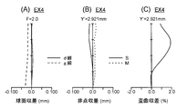
- FIG. 6 is an aberration diagram of Example 4.
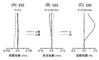
- FIG. 6 is an aberration diagram of Example 5.
- FIG. 10 is an aberration diagram of Example 6.
- FIG. 10 is an aberration diagram of Example 7.
- the schematic diagram which shows the schematic structural example of the digital apparatus carrying an imaging lens.
- the imaging lens and the like according to the present invention will be described below.
- the first type of imaging lens is an imaging lens for forming a subject image on an imaging surface of the imaging device (for example, a photoelectric conversion unit of a solid-state imaging device), and is a positive first lens in order from the object side.
- f1 focal length of the first lens
- f2 focal length of the second lens
- the basic configuration of the first type includes a positive first lens, an aperture stop, a positive second lens, and a negative third lens. And a positive fourth lens and a negative fifth lens.
- a positive lens group including a first lens, an aperture stop, a second lens, a third lens, and a fourth lens, and a negative fifth lens are arranged in a so-called telephoto type arrangement. Therefore, this configuration is advantageous for reducing the overall length of the imaging lens.
- Conditional expression (1) optimizes the power arrangement before and after the aperture by setting the focal length of the first lens and the second lens to an appropriate range (power: an amount defined by the reciprocal of the focal length), and the total length Is a conditional expression for appropriately achieving the shortening of the lens and the correction of aberration.
- conditional expression (1) it is possible to prevent the focal length of the first lens from becoming too long relative to the focal length of the second lens, and to maintain symmetry before and after the aperture. It is possible to prevent the field curvature from being excessively overturned and the distortion aberration from being greatly plus (cushion type). Furthermore, shortening of the overall lens length can be achieved.
- the second type of imaging lens is an imaging lens for forming a subject image on an imaging surface of the imaging element (for example, a photoelectric conversion unit of a solid-state imaging element), and is a positive first lens in order from the object side.
- a positive second lens, a negative third lens, a positive fourth lens, and a negative fifth lens which satisfy the following conditional expression (2).
- f3 focal length of the third lens
- f focal length of the entire imaging lens system, It is.
- the optical element having power is five lenses.
- the second type basic configuration includes a positive first lens, a positive second lens, a negative third lens, and a positive lens. It consists of a fourth lens and a negative fifth lens.
- a positive lens group including a first lens, a second lens, a third lens, and a fourth lens and a negative fifth lens are in a so-called telephoto type arrangement. Therefore, this configuration is advantageous for reducing the overall length of the imaging lens.
- Conditional expression (2) is a conditional expression for achieving shortening of the entire length of the imaging lens and good aberration correction by setting the focal length of the third lens in an appropriate range. If the upper limit of conditional expression (2) is exceeded, the negative power of the third lens becomes too strong, making it difficult to shorten the entire length of the imaging lens. Further, higher-order spherical aberration and coma aberration are generated in the third lens. If the lower limit of conditional expression (2) is not reached, the negative power of the third lens becomes too weak, making it difficult to correct the Petzval sum, and the imaging performance at the periphery of the screen will deteriorate.
- a third type configuration that has all the first and second type characteristic configurations. That is, from the viewpoint described above, in order from the object side, the positive first lens, the aperture stop, the positive second lens, the negative third lens, the positive fourth lens, and the negative fifth lens. It is desirable that the conditional expressions (1) and (2) are satisfied.
- a bright five-lens imaging lens of about F2.0 which is smaller than the conventional type and has various aberrations corrected well, and the It is possible to realize the provided imaging optical device. If the imaging optical device is used in a digital device such as a mobile phone or a portable information terminal, it is possible to add a high-performance image input function to the digital device in a compact manner. It can contribute to functionalization. The conditions for achieving such effects in a well-balanced manner and achieving higher optical performance, downsizing, etc. will be described below.
- conditional expression (1a) defines a more preferable condition range based on the above viewpoints, etc., among the condition ranges defined by the conditional expression (1). Therefore, the above effect can be further enhanced preferably by satisfying conditional expression (1a).
- conditional expression (2a) defines a more preferable condition range based on the above viewpoints, etc., among the condition ranges defined by the conditional expression (2). Therefore, the above effect can be further increased preferably by satisfying conditional expression (2a).
- the first lens has a convex surface facing the object side and the second lens has a convex surface facing the image side.
- the third lens has a concave surface facing the image side.
- the image side surface of the third lens concave, it is possible to easily correct lateral chromatic aberration and Petzval sum.
- Conditional expression (3) is a conditional expression for shortening the entire length of the imaging lens and achieving appropriate aberration correction by setting the focal length of the second lens in an appropriate range.
- conditional expression (3) By falling below the upper limit of conditional expression (3), it is possible to prevent the positive power of the second lens from becoming too small, and the composite principal point of the first lens to the fourth lens can be arranged closer to the object side. Shortening of the overall length of the imaging lens can be achieved.
- exceeding the lower limit of the conditional expression (3) can suppress higher-order spherical aberration and coma generated in the second lens.
- conditional expression (3a) 1.5 ⁇ f2 / f ⁇ 6.0 (3a)
- This conditional expression (3a) defines a more preferable condition range based on the above viewpoints, etc., among the condition ranges defined by the conditional expression (3). Therefore, the above effect can be further increased preferably by satisfying conditional expression (3a).
- Conditional expression (4) is a conditional expression for achieving shortening of the entire length of the imaging lens and appropriate aberration correction by setting the focal length of the first lens in an appropriate range.
- the positive power of the first lens can be prevented from becoming too small, and the composite principal point of the first lens to the fourth lens can be arranged closer to the object side. Shortening of the overall length of the imaging lens can be achieved.
- the lower limit of the conditional expression (4) higher-order spherical aberration and coma generated in the first lens can be suppressed.
- conditional expression (4a) defines a more preferable condition range based on the above viewpoints, etc., among the condition ranges defined by the conditional expression (4). Therefore, the above effect can be further increased preferably by satisfying conditional expression (4a).
- Conditional expression (5) is a conditional expression for appropriately correcting axial chromatic aberration and lateral chromatic aberration by setting the dispersion of the third lens in an appropriate range.
- the lower limit of conditional expression (5) is not reached, the longitudinal chromatic aberration can be sufficiently corrected, but the lateral chromatic aberration generated by the peripheral luminous flux becomes large and difficult to correct.
- the upper limit of conditional expression (5) is exceeded, the lateral chromatic aberration of the peripheral light beam can be suppressed, but the axial chromatic aberration cannot be corrected.
- conditional expression (5a) defines a more preferable condition range based on the above viewpoints, etc., among the condition ranges defined by the conditional expression (5). Therefore, the above effect can be further increased preferably by satisfying conditional expression (5a).
- the image side surface of the fifth lens has an aspherical shape, has a negative refractive power at the center thereof, becomes weaker toward the periphery, has an inflection point, and has the following conditional expression (6 ) Is desirable.
- f focal length of the entire imaging lens system
- T5 thickness of the fifth lens on the optical axis, It is.
- the negative refracting power becomes weaker as the image side surface of the fifth lens goes from the optical axis to the periphery, and the telecentric characteristic of the image side light beam can be easily secured by making the aspherical shape having an inflection point. Further, the image side surface of the fourth lens does not need to excessively weaken the negative refractive power at the periphery of the lens, and the off-axis aberration can be corrected well.
- the “inflection point” is a point on the aspheric surface where the tangent plane of the aspherical vertex is a plane perpendicular to the optical axis in the curve of the lens cross-sectional shape within the effective radius.
- Conditional expression (6) is a conditional expression for appropriately achieving the image plane of the imaging lens by setting the axial thickness of the fifth lens in an appropriate range.
- the refractive power in the vicinity of the optical axis and the refractive power in the vicinity of the fifth lens are greatly different from those of the other lenses, so that the influence of the axial thickness on the field curvature is large.
- By falling below the upper limit of conditional expression (6) it is possible to prevent the field curvature from falling to the over side.
- by exceeding the lower limit of conditional expression (6) it is possible to prevent the field curvature from falling to the under side. Therefore, by satisfying conditional expression (6), it is possible to prevent the image plane property of the imaging lens from falling too much toward the over side or the under side.
- conditional expression (6a) defines a more preferable condition range based on the above viewpoints, etc., among the condition ranges defined by the conditional expression (6). Therefore, the above effect can be further enhanced preferably by satisfying conditional expression (6a).
- the imaging lens has only a plastic lens as a lens.
- a solid-state imaging device having the same number of pixels has been developed with a small pixel pitch and consequently a small imaging surface size.
- all lenses are made of plastic lenses manufactured by injection molding, so that even lenses with small radii of curvature and outer diameters are inexpensive. Mass production is possible.
- the plastic lens can lower the press temperature, it is possible to suppress the wear of the molding die, and as a result, the number of replacements and maintenance times of the molding die can be reduced, and the cost can be reduced.
- the imaging lens according to the present invention is suitable for use as an imaging lens for a digital device with an image input function (for example, a portable terminal). By combining this with an imaging device or the like, an image of a subject is optically captured.
- An imaging optical device that outputs an electrical signal can be configured.
- the imaging optical device is an optical device that constitutes a main component of a camera used for still image shooting and moving image shooting of a subject, for example, an imaging lens that forms an optical image of an object in order from the object (that is, subject) side, And an imaging device that converts an optical image formed by the imaging lens into an electrical signal.
- the imaging lens having the above-described characteristic configuration is arranged so that an optical image of the subject is formed on the light receiving surface (that is, the imaging surface) of the imaging device, and thus has high performance at a small size, low cost.
- An imaging optical device and a digital device including the imaging optical device can be realized.
- Examples of digital devices with an image input function include cameras such as digital cameras, video cameras, surveillance cameras, in-vehicle cameras, videophone cameras, etc., and personal computers, mobile terminals (for example, mobile phones, mobile computers, etc.) Small and portable information device terminals), peripheral devices (scanners, printers, etc.), cameras incorporated in or external to other digital devices, and the like.
- cameras such as digital cameras, video cameras, surveillance cameras, in-vehicle cameras, videophone cameras, etc.
- mobile terminals for example, mobile phones, mobile computers, etc.
- Small and portable information device terminals for example, mobile phones, mobile computers, etc.
- peripheral devices scanners, printers, etc.
- cameras incorporated in or external to other digital devices and the like.
- a digital device with an image input function such as a mobile phone with a camera can be configured.
- FIG. 15 is a schematic cross-sectional view showing a schematic configuration example of a digital device DU as an example of a digital device with an image input function.
- the imaging optical device LU mounted in the digital device DU shown in FIG. 15 includes an imaging lens LN (AX: optical axis) that forms an optical image (image plane) IM of an object in order from the object (that is, subject) side, A parallel plate PT (cover glass of the image sensor SR; corresponding to an optical filter such as an optical low-pass filter and an infrared cut filter disposed as necessary) and a light receiving surface (imaging surface) SS by the imaging lens LN. And an imaging element SR that converts the optical image IM formed thereon into an electrical signal.
- AX optical axis
- the image pickup optical device LU When a digital device DU with an image input function is configured with this image pickup optical device LU, the image pickup optical device LU is usually arranged inside the body, but when necessary to realize the camera function, a form as necessary is adopted. Is possible.
- the unitized imaging optical device LU can be configured to be detachable or rotatable with respect to the main body of the digital device DU.
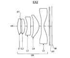
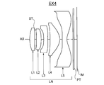
- the imaging lens LN has a single-focus five-lens configuration including the first to fifth lenses L1 to L5 in order from the object side, and forms the optical image IM on the light receiving surface SS of the imaging element SR. It has become.
- the image sensor SR for example, a solid-state image sensor such as a CCD image sensor or a CMOS image sensor having a plurality of pixels is used. Since the imaging lens LN is provided so that the optical image IM of the subject is formed on the light receiving surface SS which is a photoelectric conversion unit of the imaging element SR, the optical image IM formed by the imaging lens LN is the imaging element. It is converted into an electric signal by SR.
- the digital device DU includes a signal processing unit 1, a control unit 2, a memory 3, an operation unit 4, a display unit 5 and the like in addition to the imaging optical device LU.
- the signal generated by the image sensor SR is subjected to predetermined digital image processing, image compression processing, and the like as required by the signal processing unit 1 and recorded as a digital video signal in the memory 3 (semiconductor memory, optical disk, etc.) In some cases, it is transmitted to other devices via a cable or converted into an infrared signal or the like (for example, a communication function of a mobile phone).
- the control unit 2 is composed of a microcomputer, and controls functions such as a photographing function (still image photographing function, moving image photographing function, etc.), an image reproduction function, etc .; and a lens moving mechanism for focusing, etc.
- the control unit 2 controls the imaging optical device LU so as to perform at least one of still image shooting and moving image shooting of a subject.
- the display unit 5 includes a display such as a liquid crystal monitor, and displays an image using an image signal converted by the image sensor SR or image information recorded in the memory 3.
- the operation unit 4 is a part including operation members such as an operation button (for example, a release button) and an operation dial (for example, a shooting mode dial), and transmits information input by the operator to the control unit 2.
- FIGS. 1, 3, 5, 7, 9, 11, and 13 show first to seventh embodiments of the imaging lens LN in an infinite focus state in optical cross sections.
- the j-th lens Lj is a lens located at the j-th from the object side, and the parallel plate PT disposed on the image side of the imaging lens LN includes an optical low-pass filter, an IR cut filter, a seal glass of a solid-state imaging device, and the like. It is assumed. All the lens surfaces constituting the imaging lens LN are aspheric surfaces, and all the lenses are assumed to be made of a plastic material as an optical material. In addition, it is assumed that the entire focus is performed by moving the first lens L1 to the fifth lens L5 as a single unit for the focus position adjustment in the auto focus, the macro switching function, or the like.
- the imaging lenses LN of the first to seventh embodiments from the object side, the positive first lens L1, the aperture stop ST, the positive second lens L2, the negative third lens L3, and the positive fourth lens L4. And the negative fifth lens L5 in this order.
- the first lens L1 has a convex surface facing the object side
- the second lens L2 has a convex surface facing the image side
- the third lens L3 has a concave surface facing the image side.
- the image side surface of the fifth lens is an aspheric surface having an inflection point at a position other than the intersection with the optical axis AX.
- the plastic material has a large refractive index change at the time of temperature change, so if all lenses are made of plastic lenses, the image point position of the entire imaging lens system will fluctuate when the ambient temperature changes. It will be held. Recently, however, it has been found that mixing inorganic fine particles in a plastic material can reduce the effect of temperature changes on the plastic material. More specifically, mixing fine particles with a transparent plastic material generally causes scattering of light and lowers the transmittance, making it difficult to use as an optical material. If the wavelength is smaller than this wavelength, scattering can be substantially prevented from occurring.
- the refractive index of the plastic material decreases as the temperature increases, but the refractive index of the inorganic particles increases as the temperature increases. Therefore, it is possible to make almost no change in the refractive index by using these temperature dependencies so as to cancel each other.
- a plastic material with extremely low temperature dependency of the refractive index can be obtained.
- niobium oxide (Nb 2 O 5 ) in an acrylic resin a change in refractive index due to a temperature change can be reduced.
- such a positive lens having a relatively large refractive power for example, the first lens L1 and the fourth lens L4 or all the lenses (the first to fifth lenses L1 to L5) can be used in this way.
- a plastic material in which various inorganic particles are dispersed it is possible to suppress the image point position fluctuation at the time of temperature change of the entire imaging lens LN system.
- the principal ray incident angle of the light beam incident on the imaging surface of the solid-state imaging device is not necessarily designed to be sufficiently small in the periphery of the imaging surface.
- shading can be reduced by reviewing the arrangement of the color filters of the solid-state imaging device and the on-chip microlens array. Specifically, if the pitch of the arrangement of the color filters and the on-chip microlens array is set slightly smaller than the pixel pitch of the image pickup surface of the image pickup device, the color filter for each pixel becomes closer to the periphery of the image pickup surface.
- the on-chip microlens array is shifted to the optical axis side of the imaging lens, the obliquely incident light beam can be efficiently guided to the light receiving portion of each pixel. Thereby, the shading which generate
- a design example aiming at further miniaturization is provided for the portion in which the requirement is relaxed.
- Examples 1 to 7 (EX1 to EX7) listed here are numerical examples corresponding to the first to seventh embodiments, respectively, and are optical configuration diagrams showing the first to seventh embodiments. (FIGS. 1, 3, 5, 7, 9, 11, and 13) show the lens configurations of the corresponding Examples 1 to 7, respectively.
- the maximum image height), the total lens length (TL, mm), and the half angle of view ( ⁇ , °) are shown, and the focal length (mm) of each lens is shown as single lens data.
- the back focus fB used here is the distance from the image side surface of the parallel plate PT to the image plane IM
- the total lens length TL is the distance from the front lens surface to the image plane IM.
- Table 1 shows values corresponding to the conditional expressions of the respective examples.
- 2, 4, 6, 8, 10, 12, and 14 are aberration diagrams of Examples 1 to 7 (EX 1 to 7), where (A) is spherical aberration (mm), (B ) Shows astigmatism (mm), and (C) shows distortion (%).
- the solid line shows the spherical aberration amount for the d-line (wavelength 587.56 nm)
- the broken line shows the spherical aberration amount for the g-line (wavelength 435.84 nm)
- the vertical axis represents the F value.
- the broken line M represents the meridional image plane with respect to the d-line
- the solid line S represents the sagittal image plane with respect to the d-line by the amount of deviation in the optical axis AX direction from the paraxial image plane.
- the axis represents the image height Y ′ (mm).
- the horizontal axis represents the distortion with respect to the d-line
- the vertical axis represents the image height Y ′ (mm). Note that the maximum image height Y ′ corresponds to half the diagonal length of the imaging surface SS of the imaging element SR.
- the imaging lens LN (FIG. 1) of Example 1 includes, in order from the object side, a positive first lens L1, a positive second lens L2, a negative third lens L3, and a positive fourth lens L4.
- the negative fifth lens L5 is composed of an aspherical lens surface, and an aperture stop ST is disposed between the first lens L1 and the second lens L2.
- the first lens L1 is a positive meniscus lens convex toward the object side
- the second lens L2 is a positive meniscus lens convex toward the image side
- the third lens L3 is
- the fourth lens L4 is a positive meniscus lens convex to the image side
- the fifth lens L5 is a negative meniscus lens concave to the image side.
- the imaging lens LN (FIG. 3) of Example 2 includes, in order from the object side, a positive first lens L1, a positive second lens L2, a negative third lens L3, and a positive fourth lens L4.
- the negative fifth lens L5 is composed of an aspherical lens surface, and an aperture stop ST is disposed between the first lens L1 and the second lens L2.
- the first lens L1 is a positive meniscus lens convex on the object side
- the second lens L2 is a biconvex positive lens
- the third lens L3 is biconcave.
- the fourth lens L4 is a negative meniscus lens convex to the image side
- the fifth lens L5 is a negative meniscus lens concave to the image side.
- the imaging lens LN (FIG. 5) of Example 3 includes, in order from the object side, a positive first lens L1, a positive second lens L2, a negative third lens L3, and a positive fourth lens L4.
- the negative fifth lens L5 is composed of an aspherical lens surface, and an aperture stop ST is disposed between the first lens L1 and the second lens L2.
- the first lens L1 is a positive meniscus lens convex on the object side
- the second lens L2 is a biconvex positive lens
- the third lens L3 is biconcave.
- the fourth lens L4 is a negative meniscus lens convex to the image side
- the fifth lens L5 is a negative meniscus lens concave to the image side.
- the imaging lens LN (FIG. 7) of Example 4 includes, in order from the object side, a positive first lens L1, a positive second lens L2, a negative third lens L3, a positive fourth lens L4,
- the negative fifth lens L5 is composed of an aspherical lens surface, and an aperture stop ST is disposed between the first lens L1 and the second lens L2.
- the first lens L1 is a positive meniscus lens convex toward the object side
- the second lens L2 is a positive meniscus lens convex toward the image side
- the third lens L3 is
- the fourth lens L4 is a positive meniscus lens convex to the image side
- the fifth lens L5 is a negative meniscus lens concave to the image side.
- the imaging lens LN (FIG. 9) of Example 5 includes, in order from the object side, a positive first lens L1, a positive second lens L2, a negative third lens L3, a positive fourth lens L4,
- the negative fifth lens L5 is composed of an aspherical lens surface, and an aperture stop ST is disposed between the first lens L1 and the second lens L2.
- the first lens L1 is a positive meniscus lens convex toward the object side
- the second lens L2 is a positive meniscus lens convex toward the image side
- the third lens L3 is
- the fourth lens L4 is a positive meniscus lens convex to the image side
- the fifth lens L5 is a negative meniscus lens concave to the image side.
- the imaging lens LN (FIG. 11) of Example 6 includes, in order from the object side, a positive first lens L1, a positive second lens L2, a negative third lens L3, and a positive fourth lens L4.
- the negative fifth lens L5 is composed of an aspherical lens surface, and an aperture stop ST is disposed between the first lens L1 and the second lens L2.
- the first lens L1 is a positive meniscus lens convex on the object side
- the second lens L2 is a biconvex positive lens
- the third lens L3 is on the image side.
- the fourth lens L4 is a positive meniscus lens convex to the image side
- the fifth lens L5 is a negative meniscus lens concave to the image side.
- the imaging lens LN (FIG. 13) of Example 7 includes, in order from the object side, a positive first lens L1, a positive second lens L2, a negative third lens L3, and a positive fourth lens L4.
- the negative fifth lens L5 is composed of an aspherical lens surface, and an aperture stop ST is disposed between the first lens L1 and the second lens L2.
- the first lens L1 is a positive meniscus lens convex on the object side
- the second lens L2 is a biconvex positive lens
- the third lens L3 is on the image side.
- the fourth lens L4 is a positive meniscus lens convex to the image side
- the fifth lens L5 is a negative meniscus lens concave to the image side.
Landscapes
- Physics & Mathematics (AREA)
- General Physics & Mathematics (AREA)
- Optics & Photonics (AREA)
- Lenses (AREA)
- Studio Devices (AREA)
Abstract
La présente invention porte sur une lentille de capture d'image qui comprend, dans l'ordre depuis le côté objet, une première lentille positive, un arrêt, une deuxième lentille positive, une troisième lentille négative, une quatrième lentille positive et une cinquième lentille négative, qui satisfait l'expression de condition 0 < f1/f2 < 1,26 (f1 étant la distance focale de la première lentille et f2 étant la distance focale de la deuxième lentille) et forme une image d'un objet sur la surface de capture d'image d'un élément de capture d'image.
Priority Applications (1)
| Application Number | Priority Date | Filing Date | Title |
|---|---|---|---|
| JP2013539603A JP5904208B2 (ja) | 2011-10-20 | 2012-10-03 | 撮像レンズ,撮像光学装置及びデジタル機器 |
Applications Claiming Priority (4)
| Application Number | Priority Date | Filing Date | Title |
|---|---|---|---|
| JP2011230797 | 2011-10-20 | ||
| JP2011230798 | 2011-10-20 | ||
| JP2011-230798 | 2011-10-20 | ||
| JP2011-230797 | 2011-10-20 |
Publications (1)
| Publication Number | Publication Date |
|---|---|
| WO2013058111A1 true WO2013058111A1 (fr) | 2013-04-25 |
Family
ID=48140763
Family Applications (1)
| Application Number | Title | Priority Date | Filing Date |
|---|---|---|---|
| PCT/JP2012/075631 Ceased WO2013058111A1 (fr) | 2011-10-20 | 2012-10-03 | Lentille de capture d'image |
Country Status (3)
| Country | Link |
|---|---|
| JP (1) | JP5904208B2 (fr) |
| TW (1) | TW201326957A (fr) |
| WO (1) | WO2013058111A1 (fr) |
Cited By (46)
| Publication number | Priority date | Publication date | Assignee | Title |
|---|---|---|---|---|
| CN104166222A (zh) * | 2013-05-17 | 2014-11-26 | 大立光电股份有限公司 | 结像系统镜片组 |
| JP2015018233A (ja) * | 2013-07-10 | 2015-01-29 | 玉晶光電股▲ふん▼有限公司 | 光学撮像レンズ |
| JP2015075768A (ja) * | 2013-10-11 | 2015-04-20 | 玉晶光電股▲ふん▼有限公司 | 光学撮像レンズ |
| EP2947492A2 (fr) * | 2014-05-23 | 2015-11-25 | Sintai Optical (Shenzhen) Co., Ltd. | Ensemble de lentilles |
| CN105319675A (zh) * | 2014-05-26 | 2016-02-10 | 大立光电股份有限公司 | 成像光学系统、取像装置以及可携式装置 |
| US10156706B2 (en) | 2014-08-10 | 2018-12-18 | Corephotonics Ltd. | Zoom dual-aperture camera with folded lens |
| US10225479B2 (en) | 2013-06-13 | 2019-03-05 | Corephotonics Ltd. | Dual aperture zoom digital camera |
| US10288840B2 (en) | 2015-01-03 | 2019-05-14 | Corephotonics Ltd | Miniature telephoto lens module and a camera utilizing such a lens module |
| US10288896B2 (en) | 2013-07-04 | 2019-05-14 | Corephotonics Ltd. | Thin dual-aperture zoom digital camera |
| US10317647B2 (en) | 2013-07-04 | 2019-06-11 | Corephotonics Ltd | Miniature telephoto lens assembly |
| US10534153B2 (en) | 2017-02-23 | 2020-01-14 | Corephotonics Ltd. | Folded camera lens designs |
| US10620404B2 (en) | 2015-12-30 | 2020-04-14 | Sintai Optical (Shenzhen) Co., Ltd. | Optical lens |
| CN111474688A (zh) * | 2020-06-23 | 2020-07-31 | 瑞声通讯科技(常州)有限公司 | 摄像光学镜头 |
| CN111474687A (zh) * | 2020-06-10 | 2020-07-31 | 浙江舜宇光学有限公司 | 摄像镜头组 |
| CN111580248A (zh) * | 2020-07-07 | 2020-08-25 | 浙江舜宇光学有限公司 | 摄像镜头组 |
| CN111624743A (zh) * | 2020-07-22 | 2020-09-04 | 常州市瑞泰光电有限公司 | 摄像光学镜头 |
| CN112198634A (zh) * | 2020-11-11 | 2021-01-08 | 浙江舜宇光学有限公司 | 光学成像系统 |
| US10948696B2 (en) | 2017-07-23 | 2021-03-16 | Corephotonics Ltd. | Compact folded lenses with large apertures |
| US11106018B2 (en) | 2017-07-07 | 2021-08-31 | Corephotonics Ltd. | Folded camera prism design for preventing stray light |
| WO2022047988A1 (fr) * | 2020-09-03 | 2022-03-10 | 诚瑞光学(深圳)有限公司 | Objectif optique de dispositif de prise de vues |
| WO2022062073A1 (fr) * | 2020-09-22 | 2022-03-31 | 诚瑞光学(深圳)有限公司 | Lentille optique photographique |
| US11336830B2 (en) | 2019-01-03 | 2022-05-17 | Corephotonics Ltd. | Multi-aperture cameras with at least one two state zoom camera |
| US11333845B2 (en) | 2018-03-02 | 2022-05-17 | Corephotonics Ltd. | Spacer design for mitigating stray light |
| US11668910B2 (en) | 2019-08-21 | 2023-06-06 | Corephotonics Ltd. | Low total track length for large sensor format including seven lenses of +−+−++− refractive powers |
| US11689708B2 (en) | 2020-01-08 | 2023-06-27 | Corephotonics Ltd. | Multi-aperture zoom digital cameras and methods of using same |
| US11770609B2 (en) | 2020-05-30 | 2023-09-26 | Corephotonics Ltd. | Systems and methods for obtaining a super macro image |
| US11803106B2 (en) | 2020-12-01 | 2023-10-31 | Corephotonics Ltd. | Folded camera with continuously adaptive zoom factor |
| US11860515B2 (en) | 2019-11-25 | 2024-01-02 | Corephotonics Ltd. | Folded zoom camera module with adaptive aperture |
| US11886037B2 (en) | 2020-09-24 | 2024-01-30 | Samsung Electro-Mechanics Co., Ltd. | Optical imaging system |
| US11914117B2 (en) | 2020-07-31 | 2024-02-27 | Corephotonics Ltd. | Folded macro-tele camera lens designs including six lenses of ++−+−+ or +−++−+, seven lenses of ++−++−+, or eight lenses of ++−++−++ refractive powers |
| US11930263B2 (en) | 2021-01-25 | 2024-03-12 | Corephotonics Ltd. | Slim pop-out wide camera lenses |
| US11966147B2 (en) | 2020-09-18 | 2024-04-23 | Corephotonics Ltd. | Pop-out zoom camera |
| US11985407B2 (en) | 2021-11-02 | 2024-05-14 | Corephotonics Ltd. | Compact double folded tele cameras including four lenses of +−+−, +−++; OR +−−+; or six lenses of +−+−+− or +−+−−− refractive powers |
| US11988817B2 (en) | 2017-02-08 | 2024-05-21 | Largan Precision Co., Ltd. | Optical imaging system, imaging apparatus and electronic device |
| US12001078B2 (en) | 2021-03-22 | 2024-06-04 | Corephotonics Ltd. | Folded cameras with continuously adaptive zoom factor |
| US12019363B2 (en) | 2021-09-23 | 2024-06-25 | Corephotonics Lid. | Large aperture continuous zoom folded tele cameras |
| US12050308B2 (en) | 2020-07-22 | 2024-07-30 | Corephotonics Ltd. | Folded camera lens designs including eight lenses of +−+−+++− refractive powers |
| US12066747B2 (en) | 2019-09-24 | 2024-08-20 | Corephotonics Ltd. | Slim pop-out cameras and lenses for such cameras |
| US12078868B2 (en) | 2018-05-14 | 2024-09-03 | Corephotonics Ltd. | Folded camera lens designs |
| US12216259B2 (en) | 2021-12-14 | 2025-02-04 | Corephotonics Ltd. | Large-aperture compact scanning tele cameras |
| US12228709B2 (en) | 2021-06-23 | 2025-02-18 | Corephotonics Ltd. | Compact folded tele cameras |
| US12265320B2 (en) | 2020-11-05 | 2025-04-01 | Corephotonics Ltd. | Scanning tele camera based on two prism field-of-view scanning |
| US12348870B2 (en) | 2022-04-09 | 2025-07-01 | Corephotonics Ltd. | Spin-out 360-degree camera for smartphone |
| US12368960B2 (en) | 2022-08-05 | 2025-07-22 | Corephotonics Ltd. | Systems and methods for zoom digital camera with automatic adjustable zoom field of view |
| US12461431B2 (en) | 2022-02-01 | 2025-11-04 | Corephontonics Ltd. | Slim pop-out tele camera lenses |
| US12574642B1 (en) | 2022-10-19 | 2026-03-10 | Corephotonics Ltd. | Compact folded tele cameras |
Families Citing this family (3)
| Publication number | Priority date | Publication date | Assignee | Title |
|---|---|---|---|---|
| CN106526786B (zh) * | 2015-09-11 | 2019-04-26 | 大立光电股份有限公司 | 取像用光学系统、取像装置及电子装置 |
| CN106959500B (zh) * | 2016-01-12 | 2019-12-13 | 信泰光学(深圳)有限公司 | 成像镜头 |
| CN106405796B (zh) | 2016-11-15 | 2019-08-09 | 浙江舜宇光学有限公司 | 光学成像系统及摄像装置 |
Citations (12)
| Publication number | Priority date | Publication date | Assignee | Title |
|---|---|---|---|---|
| JPS63243908A (ja) * | 1987-03-31 | 1988-10-11 | Matsushita Electric Ind Co Ltd | 投影レンズ |
| JPS6429812A (en) * | 1987-07-24 | 1989-01-31 | Minolta Camera Kk | Refraction type optical system for video projector |
| JPH0478811A (ja) * | 1990-07-20 | 1992-03-12 | Minolta Camera Co Ltd | ズームレンズ |
| JPH05188292A (ja) * | 1992-01-14 | 1993-07-30 | Konica Corp | 小型のズームレンズ |
| JP2008180964A (ja) * | 2007-01-25 | 2008-08-07 | Canon Inc | 光学系 |
| JP2009294528A (ja) * | 2008-06-06 | 2009-12-17 | Fujinon Corp | 5枚構成の撮像レンズおよび撮像装置 |
| JP2010026434A (ja) * | 2008-07-24 | 2010-02-04 | Konica Minolta Opto Inc | 撮像レンズ |
| JP2010054523A (ja) * | 2007-05-09 | 2010-03-11 | Milestone Kk | 撮像レンズ |
| JP2011133600A (ja) * | 2009-12-24 | 2011-07-07 | Sony Corp | 光学ユニットおよび撮像装置 |
| JP2011133601A (ja) * | 2009-12-24 | 2011-07-07 | Sony Corp | 光学ユニットおよび撮像装置 |
| JP2012008490A (ja) * | 2010-06-28 | 2012-01-12 | Sony Corp | 撮像レンズ及び撮像装置 |
| JP2012008489A (ja) * | 2010-06-28 | 2012-01-12 | Sony Corp | 撮像レンズ及び撮像装置 |
Family Cites Families (2)
| Publication number | Priority date | Publication date | Assignee | Title |
|---|---|---|---|---|
| TWI416198B (zh) * | 2010-11-19 | 2013-11-21 | Largan Precision Co Ltd | 光學取像系統 |
| KR101897055B1 (ko) * | 2011-08-31 | 2018-10-29 | 엘지이노텍 주식회사 | 광학계 |
-
2012
- 2012-10-03 JP JP2013539603A patent/JP5904208B2/ja active Active
- 2012-10-03 WO PCT/JP2012/075631 patent/WO2013058111A1/fr not_active Ceased
- 2012-10-12 TW TW101137726A patent/TW201326957A/zh unknown
Patent Citations (12)
| Publication number | Priority date | Publication date | Assignee | Title |
|---|---|---|---|---|
| JPS63243908A (ja) * | 1987-03-31 | 1988-10-11 | Matsushita Electric Ind Co Ltd | 投影レンズ |
| JPS6429812A (en) * | 1987-07-24 | 1989-01-31 | Minolta Camera Kk | Refraction type optical system for video projector |
| JPH0478811A (ja) * | 1990-07-20 | 1992-03-12 | Minolta Camera Co Ltd | ズームレンズ |
| JPH05188292A (ja) * | 1992-01-14 | 1993-07-30 | Konica Corp | 小型のズームレンズ |
| JP2008180964A (ja) * | 2007-01-25 | 2008-08-07 | Canon Inc | 光学系 |
| JP2010054523A (ja) * | 2007-05-09 | 2010-03-11 | Milestone Kk | 撮像レンズ |
| JP2009294528A (ja) * | 2008-06-06 | 2009-12-17 | Fujinon Corp | 5枚構成の撮像レンズおよび撮像装置 |
| JP2010026434A (ja) * | 2008-07-24 | 2010-02-04 | Konica Minolta Opto Inc | 撮像レンズ |
| JP2011133600A (ja) * | 2009-12-24 | 2011-07-07 | Sony Corp | 光学ユニットおよび撮像装置 |
| JP2011133601A (ja) * | 2009-12-24 | 2011-07-07 | Sony Corp | 光学ユニットおよび撮像装置 |
| JP2012008490A (ja) * | 2010-06-28 | 2012-01-12 | Sony Corp | 撮像レンズ及び撮像装置 |
| JP2012008489A (ja) * | 2010-06-28 | 2012-01-12 | Sony Corp | 撮像レンズ及び撮像装置 |
Cited By (148)
| Publication number | Priority date | Publication date | Assignee | Title |
|---|---|---|---|---|
| CN104166222A (zh) * | 2013-05-17 | 2014-11-26 | 大立光电股份有限公司 | 结像系统镜片组 |
| CN104166222B (zh) * | 2013-05-17 | 2016-06-08 | 大立光电股份有限公司 | 结像系统镜片组 |
| US10326942B2 (en) | 2013-06-13 | 2019-06-18 | Corephotonics Ltd. | Dual aperture zoom digital camera |
| US11470257B2 (en) | 2013-06-13 | 2022-10-11 | Corephotonics Ltd. | Dual aperture zoom digital camera |
| US11838635B2 (en) | 2013-06-13 | 2023-12-05 | Corephotonics Ltd. | Dual aperture zoom digital camera |
| US10904444B2 (en) | 2013-06-13 | 2021-01-26 | Corephotonics Ltd. | Dual aperture zoom digital camera |
| US12069371B2 (en) | 2013-06-13 | 2024-08-20 | Corephotonics Lid. | Dual aperture zoom digital camera |
| US10841500B2 (en) | 2013-06-13 | 2020-11-17 | Corephotonics Ltd. | Dual aperture zoom digital camera |
| US12262120B2 (en) | 2013-06-13 | 2025-03-25 | Corephotonics Ltd. | Dual aperture zoom digital camera |
| US10225479B2 (en) | 2013-06-13 | 2019-03-05 | Corephotonics Ltd. | Dual aperture zoom digital camera |
| US12072475B2 (en) | 2013-07-04 | 2024-08-27 | Corephotonics Ltd. | Miniature telephoto lens assembly |
| US10620450B2 (en) | 2013-07-04 | 2020-04-14 | Corephotonics Ltd | Thin dual-aperture zoom digital camera |
| US10288896B2 (en) | 2013-07-04 | 2019-05-14 | Corephotonics Ltd. | Thin dual-aperture zoom digital camera |
| US10317647B2 (en) | 2013-07-04 | 2019-06-11 | Corephotonics Ltd | Miniature telephoto lens assembly |
| US11125980B2 (en) | 2013-07-04 | 2021-09-21 | Corephotonics Ltd. | Miniature telephoto lens assembly |
| US10324277B2 (en) | 2013-07-04 | 2019-06-18 | Corephotonics Ltd. | Miniature telephoto lens assembly |
| US10330897B2 (en) | 2013-07-04 | 2019-06-25 | Corephotonics Ltd. | Miniature telephoto lens assembly |
| US11287668B2 (en) | 2013-07-04 | 2022-03-29 | Corephotonics Ltd. | Thin dual-aperture zoom digital camera |
| US10437020B2 (en) | 2013-07-04 | 2019-10-08 | Corephotonics Ltd. | Miniature telephoto lens assembly |
| US10488630B2 (en) | 2013-07-04 | 2019-11-26 | Corephotonics Ltd | Miniature telephoto lens assembly |
| US11614635B2 (en) | 2013-07-04 | 2023-03-28 | Corephotonics Ltd. | Thin dual-aperture zoom digital camera |
| US11835694B2 (en) | 2013-07-04 | 2023-12-05 | Corephotonics Ltd. | Miniature telephoto lens assembly |
| US12169266B2 (en) | 2013-07-04 | 2024-12-17 | Corephotonics Ltd. | Miniature telephoto lens assembly |
| US11953659B2 (en) | 2013-07-04 | 2024-04-09 | Corephotonics Ltd. | Miniature telephoto lens assembly |
| US10962745B2 (en) | 2013-07-04 | 2021-03-30 | Corephotonics Ltd | Miniature telephoto lens assembly |
| US12313824B2 (en) | 2013-07-04 | 2025-05-27 | Corephotonics Ltd. | Miniature telephoto lens assembly |
| US10795134B2 (en) | 2013-07-04 | 2020-10-06 | Corephotonics Ltd. | Miniature telephoto lens assembly |
| US12164115B2 (en) | 2013-07-04 | 2024-12-10 | Corephotonics Ltd. | Thin dual-aperture zoom digital camera |
| US11852845B2 (en) | 2013-07-04 | 2023-12-26 | Corephotonics Ltd. | Thin dual-aperture zoom digital camera |
| US12265234B2 (en) | 2013-07-04 | 2025-04-01 | Corephotonics Ltd. | Thin dual-aperture zoom digital camera |
| US9541736B2 (en) | 2013-07-10 | 2017-01-10 | Genius Electronic Optical Co., Ltd. | Mobile device and optical imaging lens thereof |
| JP2015018233A (ja) * | 2013-07-10 | 2015-01-29 | 玉晶光電股▲ふん▼有限公司 | 光学撮像レンズ |
| US10394001B2 (en) | 2013-07-10 | 2019-08-27 | Genius Electronic Optical Co., Ltd. | Mobile device and optical imaging lens thereof |
| JP2015075768A (ja) * | 2013-10-11 | 2015-04-20 | 玉晶光電股▲ふん▼有限公司 | 光学撮像レンズ |
| EP2947492A2 (fr) * | 2014-05-23 | 2015-11-25 | Sintai Optical (Shenzhen) Co., Ltd. | Ensemble de lentilles |
| US11835693B2 (en) | 2014-05-26 | 2023-12-05 | Largan Precision Co., Ltd. | Imaging optical system, image capturing device and mobile terminal |
| US10656389B2 (en) | 2014-05-26 | 2020-05-19 | Largan Precision Co., Ltd. | Imaging optical system, image capturing device and mobile terminal |
| US9335514B2 (en) | 2014-05-26 | 2016-05-10 | Largan Precision Co., Ltd. | Imaging optical system, image capturing device and mobile terminal |
| CN105319675A (zh) * | 2014-05-26 | 2016-02-10 | 大立光电股份有限公司 | 成像光学系统、取像装置以及可携式装置 |
| US11415780B2 (en) | 2014-05-26 | 2022-08-16 | Largan Precision Co., Ltd. | Imaging optical system, image capturing device and mobile terminal |
| US10222585B2 (en) | 2014-05-26 | 2019-03-05 | Largan Precision Co., Ltd. | Imaging optical system, image capturing device and mobile terminal |
| US10571665B2 (en) | 2014-08-10 | 2020-02-25 | Corephotonics Ltd. | Zoom dual-aperture camera with folded lens |
| US12007537B2 (en) | 2014-08-10 | 2024-06-11 | Corephotonics Lid. | Zoom dual-aperture camera with folded lens |
| US11042011B2 (en) | 2014-08-10 | 2021-06-22 | Corephotonics Ltd. | Zoom dual-aperture camera with folded lens |
| US10509209B2 (en) | 2014-08-10 | 2019-12-17 | Corephotonics Ltd. | Zoom dual-aperture camera with folded lens |
| US11543633B2 (en) | 2014-08-10 | 2023-01-03 | Corephotonics Ltd. | Zoom dual-aperture camera with folded lens |
| US11262559B2 (en) | 2014-08-10 | 2022-03-01 | Corephotonics Ltd | Zoom dual-aperture camera with folded lens |
| US11982796B2 (en) | 2014-08-10 | 2024-05-14 | Corephotonics Ltd. | Zoom dual-aperture camera with folded lens |
| US11002947B2 (en) | 2014-08-10 | 2021-05-11 | Corephotonics Ltd. | Zoom dual-aperture camera with folded lens |
| US10976527B2 (en) | 2014-08-10 | 2021-04-13 | Corephotonics Ltd. | Zoom dual-aperture camera with folded lens |
| US10156706B2 (en) | 2014-08-10 | 2018-12-18 | Corephotonics Ltd. | Zoom dual-aperture camera with folded lens |
| US11703668B2 (en) | 2014-08-10 | 2023-07-18 | Corephotonics Ltd. | Zoom dual-aperture camera with folded lens |
| US12105268B2 (en) | 2014-08-10 | 2024-10-01 | Corephotonics Ltd. | Zoom dual-aperture camera with folded lens |
| US12216246B2 (en) | 2015-01-03 | 2025-02-04 | Corephotonics Ltd. | Miniature telephoto lens module and a camera utilizing such a lens module |
| US11125975B2 (en) | 2015-01-03 | 2021-09-21 | Corephotonics Ltd. | Miniature telephoto lens module and a camera utilizing such a lens module |
| US10288840B2 (en) | 2015-01-03 | 2019-05-14 | Corephotonics Ltd | Miniature telephoto lens module and a camera utilizing such a lens module |
| US12259524B2 (en) | 2015-01-03 | 2025-03-25 | Corephotonics Ltd. | Miniature telephoto lens module and a camera utilizing such a lens module |
| US12405448B2 (en) | 2015-01-03 | 2025-09-02 | Corephotonics Ltd. | Miniature telephoto lens module and a camera utilizing such a lens module |
| US11994654B2 (en) | 2015-01-03 | 2024-05-28 | Corephotonics Ltd. | Miniature telephoto lens module and a camera utilizing such a lens module |
| US10620404B2 (en) | 2015-12-30 | 2020-04-14 | Sintai Optical (Shenzhen) Co., Ltd. | Optical lens |
| US11988817B2 (en) | 2017-02-08 | 2024-05-21 | Largan Precision Co., Ltd. | Optical imaging system, imaging apparatus and electronic device |
| US11347016B2 (en) | 2017-02-23 | 2022-05-31 | Corephotonics Ltd. | Folded camera lens designs |
| US11347020B2 (en) | 2017-02-23 | 2022-05-31 | Corephotonics Ltd. | Folded camera lens designs |
| US10670827B2 (en) | 2017-02-23 | 2020-06-02 | Corephotonics Ltd. | Folded camera lens designs |
| US10571644B2 (en) | 2017-02-23 | 2020-02-25 | Corephotonics Ltd. | Folded camera lens designs |
| US10534153B2 (en) | 2017-02-23 | 2020-01-14 | Corephotonics Ltd. | Folded camera lens designs |
| US11668894B2 (en) | 2017-02-23 | 2023-06-06 | Corephotonics Ltd. | Folded camera lens designs |
| US12066683B2 (en) | 2017-02-23 | 2024-08-20 | Corephotonics Ltd. | Folded camera lens designs |
| US12345943B2 (en) | 2017-02-23 | 2025-07-01 | Corephotonics Ltd. | Folded camera lens designs |
| US11106018B2 (en) | 2017-07-07 | 2021-08-31 | Corephotonics Ltd. | Folded camera prism design for preventing stray light |
| US12105259B2 (en) | 2017-07-23 | 2024-10-01 | Corephotonics Ltd. | Compact folded lenses with large apertures |
| US10948696B2 (en) | 2017-07-23 | 2021-03-16 | Corephotonics Ltd. | Compact folded lenses with large apertures |
| US11333845B2 (en) | 2018-03-02 | 2022-05-17 | Corephotonics Ltd. | Spacer design for mitigating stray light |
| US11675155B2 (en) | 2018-03-02 | 2023-06-13 | Corephotonics Ltd. | Spacer design for mitigating stray light |
| US12078868B2 (en) | 2018-05-14 | 2024-09-03 | Corephotonics Ltd. | Folded camera lens designs |
| US12167135B2 (en) | 2019-01-03 | 2024-12-10 | Corephotonics Ltd. | Multi-aperture cameras with at least one two state zoom camera |
| US12244927B1 (en) | 2019-01-03 | 2025-03-04 | Corephotonics Ltd. | Multi-aperture cameras with at least one two state zoom camera |
| US11336830B2 (en) | 2019-01-03 | 2022-05-17 | Corephotonics Ltd. | Multi-aperture cameras with at least one two state zoom camera |
| US11743587B2 (en) | 2019-01-03 | 2023-08-29 | Corephotonics Ltd. | Multi-aperture cameras with at least one two state zoom camera |
| US11477386B2 (en) | 2019-01-03 | 2022-10-18 | Corephotonics Ltd. | Multi-aperture cameras with at least one two state zoom camera |
| US12335622B2 (en) | 2019-01-03 | 2025-06-17 | Corephotonics Ltd. | Multi-aperture cameras with at least one two state zoom camera |
| US11611706B2 (en) | 2019-01-03 | 2023-03-21 | Corephotonics Ltd. | Multi-aperture cameras with at least one two state zoom camera |
| US12052502B2 (en) | 2019-01-03 | 2024-07-30 | Corephotonics Ltd. | Multi-aperture cameras with at least one two state zoom camera |
| US12585090B2 (en) | 2019-08-21 | 2026-03-24 | Corephotonics Ltd. | Low total track length lens assembly including seven lenses of +−+−++− refractive powers for large sensor format |
| US11668910B2 (en) | 2019-08-21 | 2023-06-06 | Corephotonics Ltd. | Low total track length for large sensor format including seven lenses of +−+−++− refractive powers |
| US12000996B2 (en) | 2019-08-21 | 2024-06-04 | Corephotonics Ltd. | Low total track length lens assembly including seven lenses of +−+−++− refractive powers for large sensor format |
| US12222473B2 (en) | 2019-08-21 | 2025-02-11 | Corephotonics Ltd. | Low total track length lens assembly including seven lenses of +−+−++− refractive powers for large sensor format |
| US12066747B2 (en) | 2019-09-24 | 2024-08-20 | Corephotonics Ltd. | Slim pop-out cameras and lenses for such cameras |
| US12072609B2 (en) | 2019-09-24 | 2024-08-27 | Corephotonics Ltd. | Slim pop-out cameras and lenses for such cameras |
| US12411392B2 (en) | 2019-09-24 | 2025-09-09 | Corephotonics Ltd. | Slim pop-out cameras and lenses for such cameras |
| US12292671B2 (en) | 2019-09-24 | 2025-05-06 | Corephotonics Ltd. | Slim pop-out cameras and lenses for such cameras |
| US12326652B2 (en) | 2019-11-25 | 2025-06-10 | Corephotonics Ltd. | Folded zoom camera module with adaptive aperture |
| US11860515B2 (en) | 2019-11-25 | 2024-01-02 | Corephotonics Ltd. | Folded zoom camera module with adaptive aperture |
| US11689708B2 (en) | 2020-01-08 | 2023-06-27 | Corephotonics Ltd. | Multi-aperture zoom digital cameras and methods of using same |
| US12101455B2 (en) | 2020-01-08 | 2024-09-24 | Corephotonics Lid. | Multi-aperture zoom digital cameras and methods of using same |
| US11770609B2 (en) | 2020-05-30 | 2023-09-26 | Corephotonics Ltd. | Systems and methods for obtaining a super macro image |
| US11962901B2 (en) | 2020-05-30 | 2024-04-16 | Corephotonics Ltd. | Systems and methods for obtaining a super macro image |
| US12395733B2 (en) | 2020-05-30 | 2025-08-19 | Corephotonics Ltd. | Systems and methods for obtaining a super macro image |
| US12167130B2 (en) | 2020-05-30 | 2024-12-10 | Corephotonics Ltd. | Systems and methods for obtaining a super macro image |
| CN111474687B (zh) * | 2020-06-10 | 2025-07-29 | 浙江舜宇光学有限公司 | 摄像镜头组 |
| CN111474687A (zh) * | 2020-06-10 | 2020-07-31 | 浙江舜宇光学有限公司 | 摄像镜头组 |
| US12399348B2 (en) | 2020-06-10 | 2025-08-26 | Zhejiang Sunny Optics Co., Ltd | Camera lens group |
| JP2022003383A (ja) * | 2020-06-23 | 2022-01-11 | エーエーシー オプティクス (チャンジョウ)カンパニーリミテッド | 撮像光学レンズ |
| JP7082180B2 (ja) | 2020-06-23 | 2022-06-07 | エーエーシー オプティクス (チャンジョウ)カンパニーリミテッド | 撮像光学レンズ |
| CN111474688A (zh) * | 2020-06-23 | 2020-07-31 | 瑞声通讯科技(常州)有限公司 | 摄像光学镜头 |
| WO2021258441A1 (fr) * | 2020-06-23 | 2021-12-30 | 诚瑞光学(常州)股份有限公司 | Lentille optique photographique |
| US12493169B2 (en) | 2020-07-07 | 2025-12-09 | Zhejiang Sunny Optics Co., Ltd | Camera lens group |
| CN111580248A (zh) * | 2020-07-07 | 2020-08-25 | 浙江舜宇光学有限公司 | 摄像镜头组 |
| CN111624743A (zh) * | 2020-07-22 | 2020-09-04 | 常州市瑞泰光电有限公司 | 摄像光学镜头 |
| US12392999B2 (en) | 2020-07-22 | 2025-08-19 | Corephotonics Ltd. | Folded camera lens designs including eight lenses of +-+-+++-refractive powers |
| US12050308B2 (en) | 2020-07-22 | 2024-07-30 | Corephotonics Ltd. | Folded camera lens designs including eight lenses of +−+−+++− refractive powers |
| US11914117B2 (en) | 2020-07-31 | 2024-02-27 | Corephotonics Ltd. | Folded macro-tele camera lens designs including six lenses of ++−+−+ or +−++−+, seven lenses of ++−++−+, or eight lenses of ++−++−++ refractive powers |
| US12399351B2 (en) | 2020-07-31 | 2025-08-26 | Corephontonics Ltd. | Folded macro-tele camera lens designs including six lenses of ++−+−+ or +−++−+, seven lenses of ++−++−+, or eight lenses of ++−++−++ refractive powers |
| WO2022047988A1 (fr) * | 2020-09-03 | 2022-03-10 | 诚瑞光学(深圳)有限公司 | Objectif optique de dispositif de prise de vues |
| US11966147B2 (en) | 2020-09-18 | 2024-04-23 | Corephotonics Ltd. | Pop-out zoom camera |
| US12111561B2 (en) | 2020-09-18 | 2024-10-08 | Corephotonics Ltd. | Pop-out zoom camera |
| US12298651B2 (en) | 2020-09-18 | 2025-05-13 | Corephotonics Ltd. | Pop-out zoom camera |
| WO2022062073A1 (fr) * | 2020-09-22 | 2022-03-31 | 诚瑞光学(深圳)有限公司 | Lentille optique photographique |
| US12216333B2 (en) | 2020-09-24 | 2025-02-04 | Samsung Electro-Mechanics Co., Ltd. | Optical imaging system |
| US11886037B2 (en) | 2020-09-24 | 2024-01-30 | Samsung Electro-Mechanics Co., Ltd. | Optical imaging system |
| TWI843946B (zh) * | 2020-09-24 | 2024-06-01 | 南韓商三星電機股份有限公司 | 光學成像系統、相機模組及行動終端裝置 |
| US12271105B2 (en) | 2020-11-05 | 2025-04-08 | Corephotonics Ltd. | Scanning Tele camera based on two prism field of view scanning |
| US12265320B2 (en) | 2020-11-05 | 2025-04-01 | Corephotonics Ltd. | Scanning tele camera based on two prism field-of-view scanning |
| CN112198634A (zh) * | 2020-11-11 | 2021-01-08 | 浙江舜宇光学有限公司 | 光学成像系统 |
| US12379648B2 (en) | 2020-12-01 | 2025-08-05 | Corephotonics Ltd. | Folded camera with continuously adaptive zoom factor |
| US12001125B1 (en) | 2020-12-01 | 2024-06-04 | Corephotonics Ltd. | Folded camera with continuously adaptive zoom factor |
| US11803106B2 (en) | 2020-12-01 | 2023-10-31 | Corephotonics Ltd. | Folded camera with continuously adaptive zoom factor |
| US12189272B2 (en) | 2020-12-01 | 2025-01-07 | Corephotonics Ltd. | Folded camera with continuously adaptive zoom factor |
| US11947247B2 (en) | 2020-12-01 | 2024-04-02 | Corephotonics Ltd. | Folded camera with continuously adaptive zoom factor |
| US12170832B2 (en) | 2021-01-25 | 2024-12-17 | Corephotonics Ltd. | Slim pop-out wide camera lenses |
| US11930263B2 (en) | 2021-01-25 | 2024-03-12 | Corephotonics Ltd. | Slim pop-out wide camera lenses |
| US12356062B2 (en) | 2021-01-25 | 2025-07-08 | Corephotonics Ltd. | Slim pop-out wide camera lenses |
| US12360332B2 (en) | 2021-03-22 | 2025-07-15 | Corephotonics Ltd. | Folded cameras with continuously adaptive zoom factor |
| US12001078B2 (en) | 2021-03-22 | 2024-06-04 | Corephotonics Ltd. | Folded cameras with continuously adaptive zoom factor |
| US12135465B2 (en) | 2021-03-22 | 2024-11-05 | Corephotonics Ltd. | Folded cameras with continuously adaptive zoom factor |
| US12228709B2 (en) | 2021-06-23 | 2025-02-18 | Corephotonics Ltd. | Compact folded tele cameras |
| US12332412B2 (en) | 2021-06-23 | 2025-06-17 | Corephotonics Ltd. | Compact folded Tele cameras |
| US12019363B2 (en) | 2021-09-23 | 2024-06-25 | Corephotonics Lid. | Large aperture continuous zoom folded tele cameras |
| US12210278B2 (en) | 2021-09-23 | 2025-01-28 | Corephotonic Ltd. | Large aperture continuous zoom folded Tele cameras |
| US12443099B2 (en) | 2021-09-23 | 2025-10-14 | Corephotonics Ltd. | Large aperture continuous zoom folded tele cameras |
| US11985407B2 (en) | 2021-11-02 | 2024-05-14 | Corephotonics Ltd. | Compact double folded tele cameras including four lenses of +−+−, +−++; OR +−−+; or six lenses of +−+−+− or +−+−−− refractive powers |
| US12587728B2 (en) | 2021-11-02 | 2026-03-24 | Corephotonics Ltd. | Compact double folded tele cameras including four lenses of +-+-, +-++ or +--+; or six lenses of +-+-+- or +-+--- refractive powers |
| US12216259B2 (en) | 2021-12-14 | 2025-02-04 | Corephotonics Ltd. | Large-aperture compact scanning tele cameras |
| US12326545B2 (en) | 2021-12-14 | 2025-06-10 | Corephotonics Ltd. | Large-aperture compact scanning tele cameras |
| US12461431B2 (en) | 2022-02-01 | 2025-11-04 | Corephontonics Ltd. | Slim pop-out tele camera lenses |
| US12348870B2 (en) | 2022-04-09 | 2025-07-01 | Corephotonics Ltd. | Spin-out 360-degree camera for smartphone |
| US12368960B2 (en) | 2022-08-05 | 2025-07-22 | Corephotonics Ltd. | Systems and methods for zoom digital camera with automatic adjustable zoom field of view |
| US12574642B1 (en) | 2022-10-19 | 2026-03-10 | Corephotonics Ltd. | Compact folded tele cameras |
Also Published As
| Publication number | Publication date |
|---|---|
| TW201326957A (zh) | 2013-07-01 |
| JPWO2013058111A1 (ja) | 2015-04-02 |
| JP5904208B2 (ja) | 2016-04-13 |
Similar Documents
| Publication | Publication Date | Title |
|---|---|---|
| JP5904208B2 (ja) | 撮像レンズ,撮像光学装置及びデジタル機器 | |
| JP5397538B2 (ja) | 撮像レンズ,撮像光学装置及びデジタル機器 | |
| JP5298682B2 (ja) | 撮像レンズ | |
| CN103885157B (zh) | 拍摄镜头 | |
| JP5206688B2 (ja) | 撮像レンズ及び撮像装置並びに携帯端末 | |
| CN104105992B (zh) | 摄像镜头 | |
| JP5391806B2 (ja) | 撮像レンズ,撮像光学装置及びデジタル機器 | |
| KR101580748B1 (ko) | 촬상 광학계, 촬상 장치 및 디지털 기기 | |
| JP5735712B2 (ja) | 撮像レンズおよび撮像レンズを備えた撮像装置 | |
| JP5687390B2 (ja) | 撮像レンズおよび撮像レンズを備えた撮像装置 | |
| TWI485424B (zh) | Camera lens | |
| JP5644947B2 (ja) | 広角レンズ,撮像光学装置及びデジタル機器 | |
| JP2009258286A (ja) | 撮像レンズ、撮像ユニット及び携帯端末 | |
| WO2012090729A1 (fr) | Objectif à grand angle, dispositif optique de formation d'image et équipement numérique | |
| JP2009282223A (ja) | 撮像レンズ、撮像ユニット及び携帯端末 | |
| WO2010140515A1 (fr) | Lentille de capture d'image, dispositif de capture d'image ayant une lentille de capture d'image et terminal portable ayant le dispositif de capture d'image | |
| JP2014123034A (ja) | 撮像光学系、撮像装置およびデジタル機器 | |
| JP2013140398A (ja) | 撮像レンズ | |
| WO2012164877A1 (fr) | Système optique d'imagerie, dispositif d'imagerie et appareil numérique | |
| WO2013031122A1 (fr) | Système optique de capture d'image, dispositif de capture d'image et équipement numérique | |
| JP2014142499A (ja) | 撮像レンズ,撮像光学装置及びデジタル機器 | |
| JP2017003807A (ja) | 広角レンズ,撮像光学装置及びデジタル機器 | |
| JP6287865B2 (ja) | 撮像光学系ならびに撮像装置およびデジタル機器 | |
| JP2006003900A (ja) | 小型撮像レンズ系 | |
| WO2012160761A1 (fr) | Optique d'imagerie, appareil d'imagerie et dispositif numérique |
Legal Events
| Date | Code | Title | Description |
|---|---|---|---|
| 121 | Ep: the epo has been informed by wipo that ep was designated in this application |
Ref document number: 12842361 Country of ref document: EP Kind code of ref document: A1 |
|
| ENP | Entry into the national phase |
Ref document number: 2013539603 Country of ref document: JP Kind code of ref document: A |
|
| NENP | Non-entry into the national phase |
Ref country code: DE |
|
| 122 | Ep: pct application non-entry in european phase |
Ref document number: 12842361 Country of ref document: EP Kind code of ref document: A1 |