WO2013058236A1 - 薬剤供給装置 - Google Patents
薬剤供給装置 Download PDFInfo
- Publication number
- WO2013058236A1 WO2013058236A1 PCT/JP2012/076692 JP2012076692W WO2013058236A1 WO 2013058236 A1 WO2013058236 A1 WO 2013058236A1 JP 2012076692 W JP2012076692 W JP 2012076692W WO 2013058236 A1 WO2013058236 A1 WO 2013058236A1
- Authority
- WO
- WIPO (PCT)
- Prior art keywords
- hopper
- medicine
- deformable
- passage
- deformable portion
- Prior art date
- Legal status (The legal status is an assumption and is not a legal conclusion. Google has not performed a legal analysis and makes no representation as to the accuracy of the status listed.)
- Ceased
Links
Images


Classifications
-
- A—HUMAN NECESSITIES
- A61—MEDICAL OR VETERINARY SCIENCE; HYGIENE
- A61J—CONTAINERS SPECIALLY ADAPTED FOR MEDICAL OR PHARMACEUTICAL PURPOSES; DEVICES OR METHODS SPECIALLY ADAPTED FOR BRINGING PHARMACEUTICAL PRODUCTS INTO PARTICULAR PHYSICAL OR ADMINISTERING FORMS; DEVICES FOR ADMINISTERING FOOD OR MEDICINES ORALLY; BABY COMFORTERS; DEVICES FOR RECEIVING SPITTLE
- A61J7/00—Devices for administering medicines orally, e.g. spoons; Pill counting devices; Arrangements for time indication or reminder for taking medicine
- A61J7/0076—Medicament distribution means
-
- B—PERFORMING OPERATIONS; TRANSPORTING
- B65—CONVEYING; PACKING; STORING; HANDLING THIN OR FILAMENTARY MATERIAL
- B65B—MACHINES, APPARATUS OR DEVICES FOR, OR METHODS OF, PACKAGING ARTICLES OR MATERIALS; UNPACKING
- B65B37/00—Supplying or feeding fluent-solid, plastic, or liquid material, or loose masses of small articles, to be packaged
- B65B37/04—Supplying or feeding fluent-solid, plastic, or liquid material, or loose masses of small articles, to be packaged by vibratory feeders
-
- B—PERFORMING OPERATIONS; TRANSPORTING
- B65—CONVEYING; PACKING; STORING; HANDLING THIN OR FILAMENTARY MATERIAL
- B65B—MACHINES, APPARATUS OR DEVICES FOR, OR METHODS OF, PACKAGING ARTICLES OR MATERIALS; UNPACKING
- B65B1/00—Packaging fluent solid material, e.g. powders, granular or loose fibrous material, loose masses of small articles, in individual containers or receptacles, e.g. bags, sacks, boxes, cartons, cans, or jars
- B65B1/04—Methods of, or means for, filling the material into the containers or receptacles
- B65B1/08—Methods of, or means for, filling the material into the containers or receptacles by vibratory feeders
-
- B—PERFORMING OPERATIONS; TRANSPORTING
- B65—CONVEYING; PACKING; STORING; HANDLING THIN OR FILAMENTARY MATERIAL
- B65B—MACHINES, APPARATUS OR DEVICES FOR, OR METHODS OF, PACKAGING ARTICLES OR MATERIALS; UNPACKING
- B65B39/00—Nozzles, funnels or guides for introducing articles or materials into containers or wrappers
- B65B39/001—Nozzles, funnels or guides for introducing articles or materials into containers or wrappers with flow cut-off means, e.g. valves
-
- B—PERFORMING OPERATIONS; TRANSPORTING
- B65—CONVEYING; PACKING; STORING; HANDLING THIN OR FILAMENTARY MATERIAL
- B65B—MACHINES, APPARATUS OR DEVICES FOR, OR METHODS OF, PACKAGING ARTICLES OR MATERIALS; UNPACKING
- B65B39/00—Nozzles, funnels or guides for introducing articles or materials into containers or wrappers
- B65B39/02—Expansible or contractible nozzles, funnels, or guides
-
- B—PERFORMING OPERATIONS; TRANSPORTING
- B65—CONVEYING; PACKING; STORING; HANDLING THIN OR FILAMENTARY MATERIAL
- B65B—MACHINES, APPARATUS OR DEVICES FOR, OR METHODS OF, PACKAGING ARTICLES OR MATERIALS; UNPACKING
- B65B9/00—Enclosing successive articles, or quantities of material, e.g. liquids or semiliquids, in flat, folded, or tubular webs of flexible sheet material; Subdividing filled flexible tubes to form packages
- B65B9/06—Enclosing successive articles, or quantities of material, in a longitudinally-folded web, or in a web folded into a tube about the articles or quantities of material placed upon it
- B65B9/073—Enclosing successive articles, or quantities of material, in a longitudinally-folded web, or in a web folded into a tube about the articles or quantities of material placed upon it the web having intermittent motion
-
- B—PERFORMING OPERATIONS; TRANSPORTING
- B65—CONVEYING; PACKING; STORING; HANDLING THIN OR FILAMENTARY MATERIAL
- B65D—CONTAINERS FOR STORAGE OR TRANSPORT OF ARTICLES OR MATERIALS, e.g. BAGS, BARRELS, BOTTLES, BOXES, CANS, CARTONS, CRATES, DRUMS, JARS, TANKS, HOPPERS, FORWARDING CONTAINERS; ACCESSORIES, CLOSURES, OR FITTINGS THEREFOR; PACKAGING ELEMENTS; PACKAGES
- B65D83/00—Containers or packages with special means for dispensing contents
- B65D83/06—Containers or packages with special means for dispensing contents for dispensing powdered or granular material
-
- B—PERFORMING OPERATIONS; TRANSPORTING
- B65—CONVEYING; PACKING; STORING; HANDLING THIN OR FILAMENTARY MATERIAL
- B65B—MACHINES, APPARATUS OR DEVICES FOR, OR METHODS OF, PACKAGING ARTICLES OR MATERIALS; UNPACKING
- B65B39/00—Nozzles, funnels or guides for introducing articles or materials into containers or wrappers
- B65B39/06—Nozzles, funnels or guides for introducing articles or materials into containers or wrappers adapted to support containers or wrappers
- B65B39/08—Nozzles, funnels or guides for introducing articles or materials into containers or wrappers adapted to support containers or wrappers by means of clamps
-
- B—PERFORMING OPERATIONS; TRANSPORTING
- B65—CONVEYING; PACKING; STORING; HANDLING THIN OR FILAMENTARY MATERIAL
- B65B—MACHINES, APPARATUS OR DEVICES FOR, OR METHODS OF, PACKAGING ARTICLES OR MATERIALS; UNPACKING
- B65B39/00—Nozzles, funnels or guides for introducing articles or materials into containers or wrappers
- B65B39/12—Nozzles, funnels or guides for introducing articles or materials into containers or wrappers movable towards or away from container or wrapper during filling or depositing
Definitions
- the present invention relates to a medicine supply apparatus including a hopper having a passage through which medicine can pass downward.
- the medicine packaging device has a built-in medicine supply device.
- the medicine supply device includes a hopper.
- the hopper has a passage through which fluid drugs such as powders and tablets can pass downward (for example, Patent Document 1).
- the hopper described in Patent Document 1 includes a supply container that can temporarily store a supplied medicine such as powder.
- the lower end of the supply container is open.
- the supply container is provided with an opening / closing plate capable of closing or opening the opened portion in the form of a hinge support. And a medicine can be taken out from a supply container by moving an opening-and-closing plate.
- an object of the present invention is to provide a medicine supply device including a hopper in which medicine hardly remains.
- the present invention includes a hopper having a passage through which a medicine can pass downward, and a deformation operation portion, and a part of the lower portion of the hopper is a deformable portion having flexibility, and the deformation
- the possible portion is deformable to open and close the passage
- the deformation operation portion is configured to deform the deformable portion to open and close the passage, and to apply vibration to the deformable portion
- the medicine attached to the inner surface of the deformable portion is processed by the applied vibration.
- the said deformable part is equipped with the hopper side latching
- the said deformation operation part is the said deformation
- the deformation operation unit includes a pair of operation pieces positioned so as to sandwich the deformable portion from one side and the other side across the passage, and each operation piece includes the pair of operation pieces in the deformable portion.
- the vibration may be generated by repeating the movement in the direction of expanding the passage and the movement in the direction of narrowing.
- the present invention includes a hopper having a passage through which a medicine can pass downward, an opening / closing part, and a deformable part exciting part, wherein a part of the lower part of the hopper is flexible.
- the deformable portion is deformable so as to open and close the passage, and the opening and closing portion is configured to open and close the passage by deforming the deformable portion.
- the exciter for the deformable part is configured to apply vibration to the deformable part, and is a drug supply device that treats the drug attached to the inner surface of the deformable part by the applied vibration.
- the treatment of the medicine may be to separate the medicine attached to the inner surface of the deformable portion from the inner surface when the deformable portion vibrates.
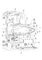
- FIG. 1 is a perspective view showing a hopper according to an embodiment of the present invention as seen from the bottom side.
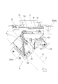
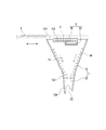
- FIG. 2 is a front view of an essential part showing a medicine packaging device to which a hopper according to an embodiment of the present invention is attached.
- FIG. 3 is a side view of the main part showing the periphery of the opening / closing part in the medicine packaging apparatus to which the hopper according to one embodiment of the present invention is attached.
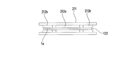
- FIG. 4A is a schematic cross-sectional view along the pressing portion showing the open / close state of the deformable portion by the open / close portion according to the embodiment of the present invention, and shows the open state.
- FIG. 1 is a perspective view showing a hopper according to an embodiment of the present invention as seen from the bottom side.
- FIG. 2 is a front view of an essential part showing a medicine packaging device to which a hopper according to an embodiment of the present invention is attached.
- FIG. 3 is a side view of the main part showing the periphery
- FIG. 4B is a schematic cross-sectional view along the pressing portion showing the open / close state of the deformable portion by the open / close portion according to the embodiment of the present invention, and shows a closed state.
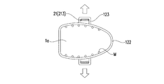
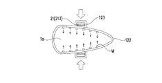
- FIG. 5A is a schematic cross-sectional view along the pressing portion showing the open / close state of the deformable portion by the open / close portion according to the embodiment of the present invention, and shows a state further opened from the neutral state.
- FIG. 5B is a schematic diagram in a cross-sectional view along the pressing portion showing the open / close state of the deformable portion by the open / close portion according to the embodiment of the present invention, and shows a state slightly closed from the neutral state.
- FIG. 6 is a schematic longitudinal sectional view showing a hopper and an opening / closing shutter according to an embodiment of the present invention.
- the hopper 1 constitutes a part of the medicine supply device A together with a deformation operation unit 2 described later. As shown in FIG. 2, the medicine supply device A is combined with the packaging device B to form a medicine packaging device.
- the medicine M passed through the hopper 1 may be either a powder or a tablet. Moreover, a powder and a tablet may be passed through the hopper 1 together.
- the hopper 1 of the present embodiment has a shape shown in FIG. 1 and a passage 1a (see FIG. 6) through which the medicine M can pass downward.
- the hopper 1 is attached so that the passage 1a is in the vertical direction.
- the hopper 1 includes a hopper body 11 and a nozzle portion 12.
- the hopper body 11 is an upper part of the hopper 1.
- the medicine M can be stored in the hopper body 11.
- the nozzle portion 12 is located below the hopper body 11.
- the lower end of the nozzle part 12 is a medicine outlet 121.
- the medicine M stored in the hopper body 11 can be taken out from the medicine outlet 121.
- the cross sectional area of the passage 1 a is reduced in the nozzle portion 12 compared to the hopper body 11.
- there are no members for example, an opening / closing plate, a hinge, etc. constituting an opening / closing mechanism for opening and closing the passage 1a.
- the material of the hopper 1 is rubber (more specifically, silicon rubber), and the entire hopper 1 is integrally formed.
- the inner surface of the hopper 1 can be formed without seams or steps, and the medicine M can hardly remain on the inner surface.
- the part in which the medicine M can remain is excluded from the path through which the medicine M passes. Therefore, the medicine M hardly remains in the entire hopper 1.
- the present invention is not limited to the integral molding, and the hopper 1 may be formed by combining different members.
- the deformable portion 122 needs to be formed of a deformable material as described later, but the other portions can be formed using various materials. . Examples of this material include metal, hard resin, and paper. Also, the deformable portion 122 can be formed of paper or a resin sheet as well as rubber as long as it is a deformable material.
- the hopper 1 of the present embodiment has a purpose of passing the medicine M downward or keeping the medicine M in the hopper 1 like the open / close plate of the hopper described in Patent Document 1.
- the hopper 1 of this embodiment includes a deformable portion 122 for opening and closing the passage 1a.
- the medicine supply device A includes a deformation operation unit 2 as an opening / closing unit for deforming the deformable unit 122.
- the deformable part 122 and the deformation operation part 2 will be described later.
- the inner surface of the hopper 1 of the present embodiment is subjected to a surface treatment for reducing friction with the medicine M passing through the passage 1a.
- This surface treatment is a coating (for example, resin coating) made of a material different from that of the hopper 1 in this embodiment.
- chemical treatment such as melting the inner surface using a chemical substance, or physical treatment such as scraping the inner surface using sandblasting, etc. Good.
- the hopper body 11 is a portion having a trumpet shape that spreads upward, and the cross-sectional shape in the present embodiment is substantially square.
- This hopper body 11 is a frame portion 111 formed at the outer edge portion and four corners, and is surrounded by the frame portion 111, which is a relatively thick and highly rigid portion, and the frame portion 111.
- the flat plate portion 112 is relatively thin and has low rigidity.
- the frame portion 111 is provided to give shape retention. More specifically, the frame portion 111 is provided to prevent the hopper 1 from being deformed by the weight of the hopper 1 and the weight and dropping pressure of the medicine M passing through the passage 1a.
- the flat plate portion 112 is relatively low in rigidity, but this is also for saving material.
- the hopper 1 is vibrated by the vibration portion 32 described later, and the inner surface of the flat plate portion 112 is waved. This is because the remaining medicine M is shaken off.
- the upper end edge 114 of the hopper main body 11 is horizontally arranged as shown in FIG. Further, as shown in FIG. 6, a cutout portion 115 is formed on one of the four sides of the upper edge 114. As will be described later, the notch 115 is provided with a suction part 5 for sucking the remaining medicine.
- a plate-like holding portion mounting portion 113 protrudes from the outer surface.
- the hopper 1 is fixed to the medicine supply device A using the holding portion attaching portion 113.
- the holding portion mounting portion 113 is provided so as to protrude in the horizontal direction on the entire circumference of the hopper body 11, but may be implemented in various shapes as long as the hopper 1 can be fixed. Good.
- the nozzle portion 12 is provided so as to be continuous with the lower end of the hopper body 11, and has a shape in which the cross-sectional area of the passage 1a decreases as it goes downward. And the lower end of the nozzle part 12 is opened, and it is set as the chemical
- FIG. The lower end is formed in an obliquely cut shape because, as shown in FIG. 2, the medicine take-out port 121 in the medicine packaging device is on the side of the packaging paper P half-folded in the width direction. This is so as to be substantially parallel to the end side P1 so as not to hinder the conveyance of the wrapping paper P. Further, the plate thickness of the lower end edge portion 121 a around the medicine outlet 121 is thicker than other portions of the nozzle portion 12. Thereby, the shape retention property of the lower end of the nozzle part 12 is ensured.
- the material of the nozzle portion 12 is naturally silicon rubber. Therefore, the entire nozzle portion 12 becomes a deformable portion 122 having flexibility, and the deformable portion 122 can be deformed so as to open and close the passage 1a. Opening and closing is performed by the deformation operation unit 2 described later.
- the deformable portion 122 be formed of a material that can maintain the shape restoring property over a long period of time. The deformable portion 122 allows the medicine M to be temporarily stored in the hopper 1.
- the hopper 1 is formed by combining different members, only a part of the nozzle part 12 may be used as the deformable part 122 instead of the whole nozzle part 12.
- the meaning of the “opening / closing” is as follows: (1) forcibly opening and closing the passage 1a, (2) forcibly closing the passage 1a and opening it naturally by the elasticity of the deformable portion 122, etc. 3)
- the passage 1a can be forcibly opened and closed naturally by the elasticity of the deformable portion 122. It also includes the case where the passage 1a stops in a half-opened or semi-closed state. Therefore, the mode of closing the passage 1a is not limited to the one that is completely closed, and includes one that is closed with an opening that is sufficient to prevent the medicine M from being taken out. On the contrary, the mode in which the passage 1a is opened includes one in which the drug M can substantially pass even with a slight opening.
- the passage 1a in the deformable portion 122 is opened when the deformable portion 122 does not receive an external force, and is configured to be forcibly closed by the deformation operation portion 2 described later.
- the deformable portion 122 may be closed so that the deformable portion 122 is closed and opened by the deforming operation portion 2 when no external force is applied to the deformable portion 122.
- the cross-sectional shape of the deformable portion 122 has at least one short side and two long sides that are adjacent to the short side.
- the upper portion of the nozzle portion 12 has a square shape with a corner that matches the shape of the hopper body 11, and the middle portion has a corner shape with two short sides and two long sides.
- the middle portion has a corner shape with two short sides and two long sides.
- it is an isosceles triangle with a corner having one short side and two long sides.
- the deformation of the deformable portion 122 is performed by the deformation operation unit 2 described later so that the long sides approach or separate from each other. At this time, the short side of the cross-sectional shape is bent. That is, by expanding or narrowing the inner surface of the deformable portion 122, the medicine M is allowed to pass downward, or the medicine M is placed above the deformation operation portion 2 (more specifically, the pressing portion 211) of the hopper 1. You can stay in position. As described above, since the passage 1a can be opened and closed only by the deformation of the deformable portion 122, the medicine M passing through the passage 1a is configured by a mechanism that is a separate component from the hopper 1, such as the opening / closing plate described in Patent Document 1.
- the hopper 1 can be made disposable without ultimately assuming the cleaning of the hopper 1.
- the deformable portion 122 includes a hopper side locking portion 123 on the outer surface.
- locking part 123 is for deforming the deformable part 122 in the direction which opens the channel
- the deformable portion 122 of the present embodiment has a pocket shape that opens downward on the outer surface of each long side of the deformable portion 122.
- a hooking portion 213 (described later) of the operation piece 21 is inserted into the pocket-shaped hopper side locking portion 123.
- route 1a in the deformable part 122 can be opened with operation
- the hopper side locking portion 123 only needs to be able to lock the operation piece 21 so that the deformable portion 122 is interlocked with the operation of the operation piece 21.
- various operations such as adhesion, metal fitting, and fitting can be performed. Can be adopted.
- the hopper side locking portion 123 has a pocket shape, when the hopper 1 is removed, the hook portion 213 of the operation piece 21 can be moved from the hopper side locking portion 123 only by moving the hopper 1 upward. Come off. Therefore, the removal operation of the hopper 1 is easy, and it can be said that the cleaning operation of the hopper 1 is also easy from this.
- locking part 123 may be provided in the inside of the nozzle part 12. FIG.
- a squirting prevention portion 124 is formed so as to protrude downward.
- the medicine M that has fallen into the wrapping paper P that is half-folded in the width direction may jump up and fly up (referred to as “spouting”). Since the spray prevention unit 124 can prevent the medicine M from flowing to the upstream side of the half-folded wrapping paper P, the “spout” can be suppressed.
- a reinforcing portion 124 a whose plate thickness is thicker than other portions of the nozzle portion 12 is provided in the vertical direction outside the spray prevention portion 124.
- the shape retention property of the lower end in the nozzle part 12 is ensured with the said lower end edge part 121a.
- the formation of the ejection preventing portion 124 is not essential and may be omitted.
- This medicine supply device A includes the hopper 1 and a deformation operation part 2 as an opening / closing part for opening and closing the passage 1a so that a predetermined amount of medicine M can be taken out.
- the medicine packaging apparatus includes the medicine supply apparatus A and the packaging apparatus B for wrapping the medicine M supplied by the medicine supply apparatus A with the wrapping paper P. After the packaging apparatus B folds the packaging paper P continuously supplied in the length direction in the width direction and wraps the medicine M for one package supplied from the medicine supply container in the packaging paper P The periphery of the wrapping paper P is adhered by heat sealing or the like.
- the principal part of the medicine packaging device is shown in FIG. What is illustrated by a two-dot chain line is a wrapping paper P that is half-folded in the width direction. The moving direction of the wrapping paper P is a direction indicated by an arrow in the drawing.
- the lower end of the nozzle part 12 in the hopper 1 is positioned so as to be sandwiched between the half-folded wrapping paper P as shown in the drawing.
- the end face shape of the medicine outlet 121 is an isosceles triangle as shown in FIGS. 1 and 3, and the apex side in the shape is located downstream in the moving direction of the wrapping paper P.
- the deformation operation unit 2 includes a pair of operation pieces 21 provided at positions sandwiching the deformable portion 122 in the nozzle portion 12 of the hopper 1 from one side and the other side, and each operation piece 21. And a drive unit 22 for operating.
- Each operation piece 21 is made of metal and has a cross-sectional shape that lacks one side of a rectangle.
- the operation piece 21 has an elongated plate-like pressing portion 211 that can be approached so as to press the deformable portion 122 and a connecting portion 214 that extends from both ends of the pressing portion 211 to the driving portion 22. is doing.
- Each pressing part 211, 211 is provided so as to extend in an oblique direction (that is, a direction intersecting the up-down direction so as to cross the deformable part 122 in a side view).
- the pressing portions 211 and 211 are parallel with the deformable portion 122 interposed therebetween.
- each press part 211,211 is provided in parallel with the side of the packaging paper P on the outer side of the packaging paper P which moves the inside of a medicine packaging apparatus, as shown in FIG.
- each pressing portion 211 and 211 is within the line where the wrapping paper P is located (the range of the two-dot chain line in FIG. 2). And the timing at which the paper gripping portion (not shown) for holding the wrapping paper P downstream of the nozzle portion 12 holds the wrapping paper P and the timing at which the deformation operation portion 2 opens the deformable portion 12. This is because they match (that is, because the forces applied to the wrapping paper P conflict with each other), causing the wrapping paper P to break. Furthermore, if each pressing part 211, 211 is located within the line where the wrapping paper P is located, the medicine M may adhere to each pressing part 211, 211 itself.
- the operation piece 21 is provided at a position above the lower end of the hopper 1. Thereby, the positional relationship between the operation piece 21 and the passage 1a is as shown in FIG. 4A. Therefore, the operation piece 21 is separated from the medicine M passing through the passage 1 a by the hopper 1, and the medicine M does not remain around the operation piece 21. It should be noted that the operation piece 21 is provided as close to the lower end of the hopper 1 as possible so that the drop distance of the medicine M becomes smaller and “spouting” of the medicine M is less likely to occur.
- the drive unit 22 is provided on the side of the nozzle unit 12.
- the operation piece 21 on the right side in the figure moves to the left in the figure when closing the passage 1 a of the hopper 1, and the operation piece 21 on the left side in the figure moves to the right in the figure when closing the passage 1 a in the hopper 1.
- the drive unit 22 is driven by a motor, and each coupling unit 214 is moved to the left and right in the drawing by meshing of gears (not shown). During this movement, the pressing portions 211 and 211 are kept in a parallel relationship.
- the shape and operation of the pressing portion 211 are not limited to those of the present embodiment, and can be variously changed.
- a cantilever type, a cylinder drive type, an electromagnet drive type, a hinge provided at one end and a fan-like rotation can be mentioned.
- the pressing portion 211 moves relative to the deformable portion 122 and the deformable portion 122 can be deformed so as to open and close the passage 1a, it can be changed to any form.
- only the operation in the pressing direction (direction approaching the deformable portion 122) may be performed by the drive unit 22, and the operation in the opposite direction may be performed by the repulsive force of the spring or the like (regardless of the drive unit 22).
- the operation piece 21 is provided with the pressing portion 211.
- a hooking portion 213 described later may be provided.
- Each pressing part 211, 211 of the present embodiment includes a cushion part 212 having elasticity on the inner surface (that is, the part facing the deformable part 122 of the hopper 1).
- the cushion portion 212 can absorb unevenness in the thickness of the deformable portion 122 caused by a molding error of the hopper 1. That is, when the thickness of the deformable portion 122 is not uniform over the entire circumference, when the pressing portions 211 and 211 made of metal and having no elasticity directly press the deformable portion 122 as in the present embodiment, the deformable portion 122 is brought into close contact. It is difficult to completely close the passage 1a.
- the cushion portion 212 can press the portion of the deformable portion 122 whose thickness is small with a relatively large force. And the part which thickness is large in the deformable part 122 can be suppressed with a relatively small force. For this reason, the passage 1a can be completely closed. In addition, depending on the case, you may provide the cushion part 212 only in any one inner surface among each press part 211,211.
- the central cushion portion 212a in the extending direction of the pressing portions 211 and 211 has greater elasticity than the both end cushion portions 212b.
- the center cushion portion 212a is softer than the both end cushion portions 212b.
- the center-side cushion portion 212a is made of sponge, and the both-end-side cushion portions 212b are made of rubber.
- the end of the passage 1a can increase the pressing force, so that the passage 1a can be reliably closed.
- the central cushion portion 212a is thicker than the both end cushion portions 212b in order to balance the pressing force.
- the central cushion portion 212 a first presses the central side of the deformable portion 122, and a little later than that, the both end side cushion portions 212 b press the central side of the deformable portion 122. Therefore, it is possible to reliably close the passage 1a without causing uneven contact.
- the pressing portions 211 of the operation pieces 21 and 21 of the present embodiment are integrally provided with a hooking portion 213 so as to protrude upward.
- the hook portion 213 is inserted into a pocket-shaped hopper side locking portion 123 provided in the nozzle portion 12.
- the hooking portion 213 moves the deformable portion 122 in a direction to open the passage 1a.
- path 1a can be opened reliably.
- the passage 1a may be naturally opened by the elasticity of the deformable portion 122 itself without using the hook portion 213.
- the deformation operation part 2 of this embodiment is used as an opening / closing part for opening / closing the passage 1a in the deformable part 122.
- transformation operation part 2 is used also as a vibration part for a deformable part for the residual medicine process of the hopper 1 (especially the deformable part 122) (it combines).
- the deformation operation unit 2 is used to perform a process of removing the remaining medicine that is the medicine M attached to the inner surface of the hopper 1.
- the deformable unit 122 is sandwiched by the deformation operation unit 2. Thereby, the inner surfaces of the deformable portion 122 are in close contact with each other. And in the hopper 1, the chemical
- the deforming operation unit 2 is used (also used) as a deformable part vibration unit for vibrating the deformable part, so that the remaining medicine processing for each part is performed.
- the operation piece 21 moves in a direction further away from the state where the passage 1a of the hopper 1 is opened (see FIG. 4A) (see FIG. 5A). It reciprocates to repeat the movement in the approaching direction (see FIG. 5B). That is, if the state shown in FIG. 4A is a neutral state that is not opened or closed, the state shown in FIG. 5A is a state that is further opened from the neutral state, and the state shown in FIG. 5B is a state that is slightly closed from the neutral state. is there.
- the movement in the separating direction is such that the passage 1a is expanded by the hook portion 213 of the operation piece 21 coming into contact with the inner surface of the hopper side locking portion 123 of the nozzle portion 12.
- the movement in the approaching direction causes the passage 1 a to be crushed when the central cushion portion 212 a of the operation piece 21 presses the outer surface of the nozzle portion 12.
- 5A and 5B depict the shape change of the deformable portion 122 exaggerated from the actual one.
- the operation piece 21 reciprocates as described above, whereby the deformable portion 122 of the hopper 1 can be bent. And the deformable part 122 can be vibrated by repeating this reciprocation. Due to this vibration, a force in the direction of moving inward of the passage 1a as shown by an arrow in FIG. 5B is applied to the medicine M adhering to the inner surface of the deformable portion 122 as shown in FIG. 5A. Thereby, the medicine M is separated from the inner surface of the deformable portion 122. Therefore, the medicine M is shaken off from the deformable portion 122.
- the medicine M is stored on the upper inner surface of the portion where the deformation operation part 2 is provided when the passage 1a is closed. It tends to stick and remain.
- the medicine M can be shaken off intensively and effectively by vibrating the deformable portion 122 also on the inner surface of the nozzle portion 12 where the medicine M tends to remain.
- the inner surface of the deformable portion 122 can be deformed while the close contact with the inner surface of the deformable portion 122 is loosened by vibration of the deformable portion 122 It may be attached to.
- the medicine M adhering to the inner surface of the deformable portion 122 can be removed from the deformable portion 122 by suction by the suction portion 5 described later.
- the vibration generated in the deformable portion 122 when the operation piece 21 reciprocates as described above is a vibration having a constant amplitude and frequency in the present embodiment.
- the vibration may be a vibration whose amplitude and frequency change or a shocking vibration (that is, an intermittent vibration whose amplitude and frequency change).
- the reciprocation of the operation piece 21 for the residual medicine processing of the hopper 1 is performed after the packaging operation of the medicine packaging device is completed.
- the operation piece 21 operates only for opening and closing the passage 1a in the deformable portion 122 for the purpose of taking out the medicine from the hopper 1 and storing it in the hopper 1.
- the present invention is not limited to this, and each time the operation piece 21 is opened and closed for the purpose of controlling the removal of the medicine from the hopper 1, the operation piece 21 for remnant treatment of the hopper 1 is reciprocated. May be.
- the open / close shutter 4 is located above the hopper 1.
- the opening / closing shutter 4 can be translated with respect to the upper end edge 114 of the hopper 1. Then, as indicated by a broken line in FIG. 6, the opening / closing shutter 4 can be moved directly above the hopper 1 to cover the upper end opening of the hopper 1.
- the suction part 5 is located in the notch part 115 provided in the hopper main body 11.
- the suction part 5 is provided for sucking the remaining medicine in the hopper 1, and as shown in FIG. 6, the upper suction port 51 and the lower suction port 52 arranged in two stages are provided inside the hopper 11. It is open toward.
- suction is always performed during the packaging operation of the medicine packaging device.
- suction is performed after the packaging operation of the medicine packaging device is completed.
- the suction force of the lower suction port 52 is larger than the suction force from the upper suction port 51.
- the medicine (residual medicine) M is shaken off from the inner surface of the deformable part 122 by the vibration by the deformation operation part 2. Part of this medicine (residual medicine) M falls downward from the medicine outlet 121 and is received by the portion of the wrapping paper P where the medicine M is not wrapped (“empty packaging”). The other part of the medicine (residual medicine) M is sucked by the lower suction port 52.
- the opening / closing shutter 4 covers the upper end opening of the hopper 1. Thereby, since inflow of the air from the upper part of the hopper 1 is restrict
- the deforming operation unit 2 deforms the deformable portion 122 as an opening / closing portion to open / close the passage 1a, and applies vibration to the deformable portion 122 as a deformable portion vibrating portion.
- the deformation operation unit 2 is used only as an opening / closing unit, and a vibration unit 32 for vibrating the entire hopper 1 described later is used as a deformation unit vibration unit.
- a vibration unit may be provided separately.
- the opening / closing part also serves as the deformable part exciting part because the residual of the medicine M in the hopper 1 can be suppressed without increasing the manufacturing cost of the medicine supply apparatus A.
- the hopper 1 is held by a frame-like hopper holding portion 31.
- the hopper holding portion 31 is provided at a position between the upper end and the lower end of the hopper 1.
- the hopper holding unit 31 includes a fixing clip 311.
- the hopper 1 can be held on the hopper holding portion 31 by sandwiching the holding portion attaching portion 113 of the hopper 1 with the fixing clip 311.
- the hopper holding part 31 is supported by a spring 33.
- the coil spring is used as the spring 33, it is not restricted to this, Various springs, such as a leaf
- the vibration unit 32 of the present embodiment uses a vibration motor in which an eccentric weight is attached to the rotation shaft of the motor, and generates a vibration having a constant amplitude and frequency. It may be a mechanism that generates (vibration that is intermittent and changes in amplitude and frequency). Alternatively, a mechanism that generates vibration using an electromagnet or the like may be used.
- the hopper holding portion 31 is supported by the spring 33, the hopper holding portion 31 is shaken by the vibration generated by the vibrating portion 32, and accordingly, the hopper 1 is also shaken.
- the hopper 1 is made of rubber, and the rigidity of the flat plate portion 112 is lower than the rigidity of the frame portion 111. For this reason, the inner surface of the flat plate portion 112 can be waved by the entire hopper 1 by the above-described shaking, and the remaining medicine M can be effectively shaken off. It should be noted that the medicine M remaining in the hopper 1 can be more effectively shaken off by vibrating the deformable portion 122 by the deformation operation portion 2 together with the vibration portion 32. Thus, the hopper 1 can be effectively cleaned by using the vibration unit 32 and the deformation operation unit 2 together for removing the drug M (shaking off).
- the medicine supply device A includes a hopper 1 having a passage 1a through which the medicine M can pass downward, and a deformation operation unit 2.
- a part of the lower part of the hopper 1 is The deformable portion 122 is flexible.
- the deformable portion 122 can be deformed so as to open and close the passage 1a, and the deformation operation portion 2 deforms the deformable portion 122 to form the passage.
- the medicine supply device is configured to open and close 1a and to apply vibration to the deformable portion 122, and to treat the medicine M attached to the inner surface of the deformable portion 122 by the applied vibration.
- the deformable portion 122 is deformed by the vibration applied by the deformation operation portion 2. Due to this deformation, the medicine M attached to the inner surface of the deformable portion 122 is shaken off. For this reason, the process which removes the chemical
- the deformable portion 122 includes a hopper side locking portion 123 that is locked to the deformation operation portion 2 on one side and the other side across the passage 1a, and the deformation operation.
- the portion 2 includes a pair of operation pieces 21 and 21 positioned so as to sandwich the deformable portion 122 from the one side and the other side, and each operation piece 21 locks the hopper side locking portion 123. You may have the deformation operation part side latching
- the deformation operation unit 2 includes a pair of operation pieces 21 and 21 positioned so as to sandwich the deformable portion 122 from one side and the other side of the passage 1a.
- the vibration may be generated by repeating the movement of the deformable portion 122 in the direction of expanding the passage 1a and the movement in the direction of narrowing.
- the pair of operation pieces 21 and 21 generate vibration by deforming the deformable portion 122.
- the deformable portion 122 can be vibrated with a simple configuration.
- the medicine supply device A includes a hopper 1 having a passage 1a through which the medicine M can pass downward, an opening / closing part (deformation operation part) 2, and a deformable part exciting part.
- (Deformation operation part, vibration part) 2 and 32 a part of the lower part of the hopper 1 is a deformable part 122 having flexibility, and the deformable part 122 is connected to the passage 1a.
- the opening / closing portion (deformation operation portion) 2 is configured to open and close the passage 1a by deforming the deformable portion 122, and the deformable portion exciting portion (deformation).
- the operation units and excitation units (2) and (32) are configured to apply vibration to the deformable portion 122, and the drug supply for processing the drug M attached to the inner surface of the deformable portion 122 by the applied vibration.
- Device includes a hopper 1 having a passage 1a through which the medicine M can pass downward, an opening / closing part (deformation operation part) 2, and a deformable part exciting part. (De
- the deformable portion 122 is deformed by the vibration applied by the deformable portion vibrating portions (deformation operation portion, vibrating portion) 2 and 32. Due to this deformation, the medicine M attached to the inner surface of the deformable portion 122 is shaken off. For this reason, the process which removes the chemical
- the treatment of the medicine M may be to separate the medicine M attached to the inner surface of the deformable portion 122 from the inner surface 122 when the deformable portion 122 vibrates.
- the medicine M can be shaken off by the applied vibration at the lower part of the hopper 1, which is a portion of the hopper 1 where the medicine M tends to remain.
- the medicine supply device A including the hopper 1 in which the medicine M hardly remains can be provided.
- medical agent supply apparatus A which can process the said chemical
Landscapes
- Engineering & Computer Science (AREA)
- Mechanical Engineering (AREA)
- Health & Medical Sciences (AREA)
- Life Sciences & Earth Sciences (AREA)
- Animal Behavior & Ethology (AREA)
- General Health & Medical Sciences (AREA)
- Public Health (AREA)
- Veterinary Medicine (AREA)
- Basic Packing Technique (AREA)
- Supply Of Fluid Materials To The Packaging Location (AREA)
- Medical Preparation Storing Or Oral Administration Devices (AREA)
Abstract
Description
本実施形態のホッパー1は、図1に示す形状で、薬剤Mを下方へ通過させることができる通路1a(図6参照)を有する。そして、薬剤分包装置において、この通路1aが上下方向になるようにホッパー1が取り付けられる。このホッパー1は、ホッパー本体11とノズル部12とを備える。ホッパー本体11はホッパー1の上方の部分である。このホッパー本体11に薬剤Mを貯留しておくことができる。ノズル部12はホッパー本体11の下方に位置する。ノズル部12の下端は薬剤取出口121である。ホッパー本体11に貯留されている薬剤Mをこの薬剤取出口121から取り出すことができる。この薬剤Mの取り出しのため、このノズル部12においては、通路1aの横断面積がホッパー本体11に比べて縮小されている。なお、通路1aにおける、薬剤Mが通過する空間には、この通路1aを開閉するための開閉機構を構成する部材(例えば開閉板、ヒンジなど)は存在しない。
ホッパー本体11は、上広がりのラッパ状の形状とされた部分であって、本実施形態での横断面形状はほぼ正方形である。このホッパー本体11は、外縁部分及び四隅に形成される枠部111であって、板厚が相対的に厚く剛性の高い部分である枠部111と、この枠部111に囲まれ、板厚が相対的に薄く剛性の低い平板部112とを有している。この枠部111は、保形性を持たせるために設けられる。より詳しくは、この枠部111は、ホッパー1がホッパー1の自重と前記通路1aを通過する薬剤Mの重量及び落下圧力とにより変形してしまうことを防止するために設けられる。平板部112は相対的に剛性が低くなっているが、これは材料を節約するためでもあり、それと共に、後述の加振部32によってホッパー1を振動させ、平板部112の内面を波打たせることで残留する薬剤Mを振るい落とすためである。
ノズル部12は、ホッパー本体11の下端に連続するように設けられており、下方に向かうにつれ通路1aの横断面積が小さくなる形状である。そして、ノズル部12の下端は開口しており、薬剤取出口121とされている。この下端は斜めにカットされた形状とされているが、その理由は、図2に示すように、薬剤分包装置における薬剤取出口121が、幅方向に半折された分包紙Pの側端辺P1にほぼ平行となるようにし、分包紙Pの搬送を妨げないようにするためである。また、薬剤取出口121の周囲である下端縁部121aの板厚はノズル部12の他の部分よりも厚い。これにより、ノズル部12下端の保形性が確保されている。
本実施形態では、ホッパー1がシリコンゴムで一体成形されているので、ノズル部12の材質も当然ながらシリコンゴムとなる。そのため、ノズル部12の全体が可撓性を有する変形可能部122となり、この変形可能部122が通路1aを開閉するように変形可能である。開閉は後述する変形操作部2によってなされる。なお、この変形可能部122は、可撓性に加え、形状の復元性が長期にわたって維持できる材質で形成しておくことが経済性の点から望ましい。この変形可能部122により、薬剤Mをホッパー1に一旦貯留することができる。なお、別部材を組み合わせてホッパー1を形成した場合等では、ノズル部12の全体ではなく、一部だけを変形可能部122としてもよい。
変形可能部122は、外面にホッパー側係止部123を備える。このホッパー側係止部123は、通路1aを開く方向に変形可能部122を変形させるためのものである。本実施形態の変形可能部122は、図1に示すように、変形可能部122の各長辺側外面に、下向きに開口したポケット状のものである。薬剤分包装置にホッパー1が取り付けられた際には、図2に示すように、このポケット状のホッパー側係止部123に操作片21の引掛部213(後述)が差し込まれる。そして、操作片21の動作に伴い変形可能部122における通路1aを開くことができる。
ノズル部12の下端のうち、分包紙Pの移動方向(図2参照)を基準とした上流側には、下方に突出するように噴き上がり防止部124が形成されている。ここで、幅方向に半折された分包紙P内に落下した薬剤Mが上方に跳ねて舞い上がってしまうことがある(「噴き上がり」と呼ばれる)。この噴き上がり防止部124は、前記半折された分包紙Pの上流側に薬剤Mが回り込むことを妨げることができるため、前記「噴き上がり」を抑制できる。また、この噴き上がり防止部124の外側には、板厚がノズル部12の他の部分よりも厚い補強部124aが上下方向に設けられている。このため、前記下端縁部121aと共にノズル部12における下端の保形性が確保される。なお、本発明のホッパー1において噴き上がり防止部124の形成は必須ではなく、省略してもよい。
次に、薬剤供給装置A及び薬剤分包装置について説明する。この薬剤供給装置Aは、所定量の薬剤Mを取り出すことができるように、前記のホッパー1と、通路1aを開閉する開閉部としての変形操作部2とを備えている。そして、薬剤分包装置は、前記の薬剤供給装置Aと、この薬剤供給装置Aにより供給された薬剤Mを分包紙Pで包むための分包装置Bとを備えている。分包装置Bは、長さ方向に連続して供給される分包紙Pを幅方向に半折し、薬剤供給容器から供給された1包分の薬剤Mを分包紙Pに包んだ後、ヒートシールなどにより分包紙Pの周囲を接着するものである。薬剤分包装置の要部を図2に示す。二点鎖線で図示したものが幅方向に半折された分包紙Pである。この分包紙Pの移動方向は図中に矢印で示した方向である。
変形操作部2は、図3に示すように、ホッパー1のノズル部12における変形可能部122を一方側と他方側とから挟む位置に設けられた一対の操作片21と、各操作片21を動作させるための駆動部22とを有している。各々の操作片21は、金属製で断面形状が長方形の一辺を欠いた形状である。そして、この操作片21は、変形可能部122を押圧するように接近可能な、細長い板状の押圧部211と、押圧部211の両端から駆動部22へと延ばされた連結部214を有している。各押圧部211,211は、斜め方向(つまり、変形可能部122を側面視で横切るように、上下方向に対して交差する方向)へと延びるように設けられている。また、各押圧部211,211は変形可能部122を挟んで平行である。そして、各押圧部211,211は、図2に示すように、薬剤分包装置内を移動する分包紙Pの外側に、分包紙Pの側辺と平行に設けられている。
本実施形態の各押圧部211,211は、内面(つまり、ホッパー1の変形可能部122に面する部分)に弾性を有するクッション部212を備えている。このクッション部212は、ホッパー1の成形誤差により発生する変形可能部122の厚みのムラを吸収できる。つまり、変形可能部122の厚みが全周において均一でない場合、本実施形態のように金属製で弾性のない各押圧部211,211が直接変形可能部122を押圧すると、変形可能部122を密着させて通路1aを完全に閉じることが難しい。そこで、クッション部212により、変形可能部122において厚みが小さくなっている部分は相対的に大きな力で押さえることができる。そして、変形可能部122において厚みが大きくなっている部分は相対的に小さな力で抑えることができる。このため、通路1aを完全に閉じることができる。なお、場合によっては、各押圧部211,211のうち、いずれか一方の内面にのみクッション部212を備えてもよい。
本実施形態の変形操作部2は、前記変形可能部122における通路1aの開閉のための開閉部として使用される。そしてこの変形操作部2は、ホッパー1(特に変形可能部122)の残薬処理のための、変形可能部用加振部としても使用される(兼用される)。具体的に、この変形操作部2は、ホッパー1の内面に付着した薬剤Mである残薬を除去する処理を行うために使用される。
本実施形態では、図6に示すように、ホッパー1の上方に開閉シャッター4が位置している。この開閉シャッター4は、ホッパー1の上端縁114に対して平行移動が可能である。そして、図6に破線で示すように、開閉シャッター4をホッパー1の直上に移動させてホッパー1の上端開口を覆うことができる。
本実施形態では、図2に示すように、ホッパー1が枠状のホッパー保持部31に保持されている。このホッパー保持部31は、ホッパー1の上端と下端との間の位置に設けられる。このホッパー保持部31は、固定用クリップ311を備えている。この固定用クリップ311でホッパー1の保持部取付部113を挟むことにより、ホッパー1をホッパー保持部31に保持できる。また、ホッパー保持部31は、ばね33により支持されている。本実施形態では、ばね33としてコイルばねを用いているが、これに限らず、板ばねなど、種々のばねを用いることができる。
そして、本実施形態のホッパー保持部31は、ホッパー1全体を振動させる加振部32を備えている。この加振部32は、図2に示すように、ホッパー保持部31に対し、金属板製の取付部32aを介して固定されている。本実施形態の加振部32は、モーターの回転軸に偏心した錘が取り付けられてなる振動モーターが用いられ、振幅及び周波数が一定の振動を発生させるが、従来から存在する、ソレノイド等により衝撃(間欠的であり、振幅及び周波数が変化する振動)を発生させる機構であってもよい。また、電磁石等を用いて振動を発生させる機構であってもよい。
1a 通路
122 変形可能部
123 ホッパー側係止部
2 変形操作部、開閉部、変形可能部用加振部
21 操作片
211 押圧部
213 変形操作部側係止部、引掛部
31 ホッパー保持部
32 変形可能部用加振部、加振部
A 薬剤供給装置
B 分包装置
P 分包紙
M 薬剤
Claims (5)
- 薬剤を下方へ通過させることができる通路を有するホッパーと、変形操作部と、を備え、
前記ホッパーのうち下部の一部は、可撓性を有する変形可能部とされ、
前記変形可能部は、前記通路を開閉するように変形可能であり、
前記変形操作部は、前記変形可能部を変形させて前記通路を開閉するとともに、前記変形可能部に振動を加えるよう構成され、
前記加えられた振動により、前記変形可能部の内面に付着した薬剤が処理される薬剤供給装置。 - 前記変形可能部は、前記通路を挟んだ一方側と他方側とに、前記変形操作部に係止されるホッパー側係止部を備え、
前記変形操作部は、前記変形可能部を前記一方側と他方側とから挟むように位置する一対の操作片を備え、
前記各操作片は、前記ホッパー側係止部を係止する変形操作部側係止部を有する請求項1に記載の薬剤供給装置。 - 前記変形操作部は、前記変形可能部を、前記通路を挟んだ一方側と他方側とから挟むように位置する一対の操作片を備え、
前記各操作片は、前記変形可能部における前記通路を広げる方向への移動と狭める方向への移動とを繰り返すことで前記振動を発生させる請求項1または2に記載の薬剤供給装置。 - 薬剤を下方へ通過させることができる通路を有するホッパーと、開閉部と、変形可能部用加振部と、を備え、
前記ホッパーのうち下部の一部は、可撓性を有する変形可能部とされ、
前記変形可能部は、前記通路を開閉するように変形可能であり、
前記開閉部は、前記変形可能部を変形させて前記通路を開閉するよう構成され、
前記変形可能部用加振部は、前記変形可能部に振動を加えるよう構成され、
前記加えられた振動により、前記変形可能部の内面に付着した薬剤が処理される薬剤供給装置。 - 前記薬剤の処理は、前記変形可能部が振動することにより、前記変形可能部の内面に付着した薬剤を前記内面から離すことである請求項1または4に記載の薬剤供給装置。
Priority Applications (6)
| Application Number | Priority Date | Filing Date | Title |
|---|---|---|---|
| AU2012327145A AU2012327145B2 (en) | 2011-10-21 | 2012-10-16 | Medicine supply device |
| CN201280044135.7A CN103796920B (zh) | 2011-10-21 | 2012-10-16 | 药剂供给装置 |
| EP12841905.8A EP2769920A4 (en) | 2011-10-21 | 2012-10-16 | DEVICE FOR DELIVERY OF MEDICINE |
| CA2852894A CA2852894A1 (en) | 2011-10-21 | 2012-10-16 | Medicine supply apparatus |
| US14/352,425 US9393179B2 (en) | 2011-10-21 | 2012-10-16 | Medicine supply apparatus |
| KR1020147000139A KR101945420B1 (ko) | 2011-10-21 | 2012-10-16 | 약제 공급 장치 |
Applications Claiming Priority (2)
| Application Number | Priority Date | Filing Date | Title |
|---|---|---|---|
| JP2011232011A JP6244076B2 (ja) | 2011-10-21 | 2011-10-21 | 薬剤供給装置 |
| JP2011-232011 | 2011-10-21 |
Publications (1)
| Publication Number | Publication Date |
|---|---|
| WO2013058236A1 true WO2013058236A1 (ja) | 2013-04-25 |
Family
ID=48140883
Family Applications (1)
| Application Number | Title | Priority Date | Filing Date |
|---|---|---|---|
| PCT/JP2012/076692 Ceased WO2013058236A1 (ja) | 2011-10-21 | 2012-10-16 | 薬剤供給装置 |
Country Status (8)
| Country | Link |
|---|---|
| US (1) | US9393179B2 (ja) |
| EP (2) | EP3042855B1 (ja) |
| JP (1) | JP6244076B2 (ja) |
| KR (1) | KR101945420B1 (ja) |
| CN (1) | CN103796920B (ja) |
| AU (1) | AU2012327145B2 (ja) |
| CA (1) | CA2852894A1 (ja) |
| WO (1) | WO2013058236A1 (ja) |
Cited By (1)
| Publication number | Priority date | Publication date | Assignee | Title |
|---|---|---|---|---|
| EP4512726A1 (en) * | 2023-08-18 | 2025-02-26 | Eme Engel Machinefabriek En Engineering B.V. | Packaging system for producing pouches comprising a water-soluble film and a powder |
Families Citing this family (11)
| Publication number | Priority date | Publication date | Assignee | Title |
|---|---|---|---|---|
| JP5786210B2 (ja) * | 2010-09-03 | 2015-09-30 | 株式会社タカゾノテクノロジー | ホッパー及びこれを備えた薬剤供給装置 |
| JP6155511B2 (ja) * | 2013-06-17 | 2017-07-05 | システムエルエスアイ株式会社 | 薬剤分包装置 |
| JP6155512B2 (ja) * | 2013-06-17 | 2017-07-05 | システムエルエスアイ株式会社 | 薬剤分包装置 |
| FR3053895B1 (fr) * | 2016-07-13 | 2019-07-05 | Exel Industries | Dispositif d’ecoulement pour ensemble de dispersion de produit, notamment pour engin agricole |
| FI128117B (fi) | 2017-06-01 | 2019-10-15 | Vumos Oy | Annostelulaitteisto materiaalin pakkaamiseksi |
| CN110236946B (zh) * | 2019-05-08 | 2021-09-28 | 温州职业技术学院 | 家用智能自动配药机的配药装置 |
| US20220169409A1 (en) * | 2020-11-30 | 2022-06-02 | Sargento Foods Inc. | Funnels For Package Filling |
| EP4338140B1 (en) * | 2021-05-14 | 2024-09-04 | Rheavendors Industries S.p.A. | Device for supplying a ground brewing substance for preparing beverages |
| IT202100015044A1 (it) * | 2021-06-09 | 2022-12-09 | Rheavendors Ind S P A | Dispositivo di erogazione di una sostanza da infusione macinata per la preparazione di bevande |
| DE102023104495A1 (de) | 2023-02-23 | 2024-08-29 | Atec Pharmatechnik Gmbh | Anschlussvorrichtung zum Übertragen eines schüttfähigen Gutes in einen Aufnahme-Port |
| CN116395286B (zh) * | 2023-04-14 | 2024-02-09 | 丰顺县瑞丰粮油食品有限公司 | 一种面粉存储设备及方法 |
Citations (9)
| Publication number | Priority date | Publication date | Assignee | Title |
|---|---|---|---|---|
| US3278153A (en) * | 1963-06-04 | 1966-10-11 | Gorman Rupp Ind Inc | Double action pinch tube valve |
| US3308898A (en) * | 1965-09-22 | 1967-03-14 | Harper Inc Allen | Vibrated flow control valve and weigher |
| JPS5412369Y2 (ja) * | 1974-11-08 | 1979-05-31 | ||
| JPH1072094A (ja) * | 1996-08-28 | 1998-03-17 | Lion Corp | ホッパ装置 |
| JP2004196403A (ja) * | 2002-12-20 | 2004-07-15 | Yuyama Manufacturing Co Ltd | 薬剤包装装置 |
| JP2005110786A (ja) | 2003-10-03 | 2005-04-28 | Yuyama Manufacturing Co Ltd | 薬品供給容器 |
| DE202005011346U1 (de) * | 2005-07-15 | 2005-09-29 | Wegen, Martin | Dosiervorrichtung für rieselfähige Schüttgüter |
| JP2011232011A (ja) | 2010-04-30 | 2011-11-17 | Mitsubishi Electric Corp | 冷却機及び冷凍サイクル装置 |
| JP2012051629A (ja) * | 2010-09-03 | 2012-03-15 | Takazono Technology Inc | ホッパー及びこれを備えた薬剤供給装置 |
Family Cites Families (7)
| Publication number | Priority date | Publication date | Assignee | Title |
|---|---|---|---|---|
| US2936994A (en) | 1956-09-10 | 1960-05-17 | Black Products Co | Bag filling machine |
| US5127483A (en) * | 1991-02-01 | 1992-07-07 | Hough International, Inc. | Micro weighing system |
| US6196278B1 (en) * | 1997-04-01 | 2001-03-06 | Xerox Corporation | Powder filling utilizing vibrofluidization |
| CA2257027C (en) * | 1998-01-21 | 2009-12-22 | Jakob Van Dijk | A device for dosing powdered materials |
| KR100416227B1 (ko) * | 2001-10-23 | 2004-01-31 | (주)제이브이메디 | 약제분포기용 포장지의 세로접합 거리조절장치 |
| US7118010B2 (en) * | 2002-05-10 | 2006-10-10 | Oriel Therapeutics, Inc. | Apparatus, systems and related methods for dispensing and /or evaluating dry powders |
| JP4189662B2 (ja) * | 2003-07-08 | 2008-12-03 | 株式会社日立プラントテクノロジー | 固形物投入装置 |
-
2011
- 2011-10-21 JP JP2011232011A patent/JP6244076B2/ja not_active Expired - Fee Related
-
2012
- 2012-10-16 CN CN201280044135.7A patent/CN103796920B/zh not_active Expired - Fee Related
- 2012-10-16 EP EP16156061.0A patent/EP3042855B1/en not_active Not-in-force
- 2012-10-16 US US14/352,425 patent/US9393179B2/en not_active Expired - Fee Related
- 2012-10-16 EP EP12841905.8A patent/EP2769920A4/en not_active Withdrawn
- 2012-10-16 KR KR1020147000139A patent/KR101945420B1/ko not_active Expired - Fee Related
- 2012-10-16 WO PCT/JP2012/076692 patent/WO2013058236A1/ja not_active Ceased
- 2012-10-16 CA CA2852894A patent/CA2852894A1/en not_active Abandoned
- 2012-10-16 AU AU2012327145A patent/AU2012327145B2/en not_active Ceased
Patent Citations (9)
| Publication number | Priority date | Publication date | Assignee | Title |
|---|---|---|---|---|
| US3278153A (en) * | 1963-06-04 | 1966-10-11 | Gorman Rupp Ind Inc | Double action pinch tube valve |
| US3308898A (en) * | 1965-09-22 | 1967-03-14 | Harper Inc Allen | Vibrated flow control valve and weigher |
| JPS5412369Y2 (ja) * | 1974-11-08 | 1979-05-31 | ||
| JPH1072094A (ja) * | 1996-08-28 | 1998-03-17 | Lion Corp | ホッパ装置 |
| JP2004196403A (ja) * | 2002-12-20 | 2004-07-15 | Yuyama Manufacturing Co Ltd | 薬剤包装装置 |
| JP2005110786A (ja) | 2003-10-03 | 2005-04-28 | Yuyama Manufacturing Co Ltd | 薬品供給容器 |
| DE202005011346U1 (de) * | 2005-07-15 | 2005-09-29 | Wegen, Martin | Dosiervorrichtung für rieselfähige Schüttgüter |
| JP2011232011A (ja) | 2010-04-30 | 2011-11-17 | Mitsubishi Electric Corp | 冷却機及び冷凍サイクル装置 |
| JP2012051629A (ja) * | 2010-09-03 | 2012-03-15 | Takazono Technology Inc | ホッパー及びこれを備えた薬剤供給装置 |
Non-Patent Citations (1)
| Title |
|---|
| See also references of EP2769920A4 |
Cited By (2)
| Publication number | Priority date | Publication date | Assignee | Title |
|---|---|---|---|---|
| EP4512726A1 (en) * | 2023-08-18 | 2025-02-26 | Eme Engel Machinefabriek En Engineering B.V. | Packaging system for producing pouches comprising a water-soluble film and a powder |
| NL2035632B1 (en) * | 2023-08-18 | 2025-03-04 | Eme Engel Machf En Engineering B V | Packaging system for producing pouches comprising a water-soluble film and a powder |
Also Published As
| Publication number | Publication date |
|---|---|
| AU2012327145A1 (en) | 2014-05-22 |
| CA2852894A1 (en) | 2013-04-25 |
| EP2769920A1 (en) | 2014-08-27 |
| JP6244076B2 (ja) | 2017-12-06 |
| CN103796920A (zh) | 2014-05-14 |
| KR101945420B1 (ko) | 2019-02-07 |
| CN103796920B (zh) | 2016-06-29 |
| EP3042855B1 (en) | 2017-06-28 |
| AU2012327145B2 (en) | 2016-09-01 |
| JP2013086869A (ja) | 2013-05-13 |
| KR20140080476A (ko) | 2014-06-30 |
| EP2769920A4 (en) | 2015-03-18 |
| EP3042855A1 (en) | 2016-07-13 |
| US20140239016A1 (en) | 2014-08-28 |
| US9393179B2 (en) | 2016-07-19 |
Similar Documents
| Publication | Publication Date | Title |
|---|---|---|
| JP6244076B2 (ja) | 薬剤供給装置 | |
| JP5803075B2 (ja) | 薬剤供給装置 | |
| JP5786210B2 (ja) | ホッパー及びこれを備えた薬剤供給装置 | |
| JP6118993B2 (ja) | 薬剤供給装置 | |
| HK1193790A (en) | Medicine supply device | |
| HK1193790B (en) | Medicine supply device | |
| JP6111435B2 (ja) | ホッパー | |
| JP6167139B2 (ja) | ホッパー及びこれを備えた薬剤供給装置 | |
| HK1181363B (en) | Hopper and medicine supply unit provided with same | |
| HK1181362B (en) | Hopper and medicine feeding device provided with same |
Legal Events
| Date | Code | Title | Description |
|---|---|---|---|
| 121 | Ep: the epo has been informed by wipo that ep was designated in this application |
Ref document number: 12841905 Country of ref document: EP Kind code of ref document: A1 |
|
| ENP | Entry into the national phase |
Ref document number: 20147000139 Country of ref document: KR Kind code of ref document: A |
|
| ENP | Entry into the national phase |
Ref document number: 2852894 Country of ref document: CA |
|
| WWE | Wipo information: entry into national phase |
Ref document number: 14352425 Country of ref document: US |
|
| NENP | Non-entry into the national phase |
Ref country code: DE |
|
| REEP | Request for entry into the european phase |
Ref document number: 2012841905 Country of ref document: EP |
|
| WWE | Wipo information: entry into national phase |
Ref document number: 2012841905 Country of ref document: EP |
|
| ENP | Entry into the national phase |
Ref document number: 2012327145 Country of ref document: AU Date of ref document: 20121016 Kind code of ref document: A |