WO2013061436A1 - ドライガスシール構造 - Google Patents
ドライガスシール構造 Download PDFInfo
- Publication number
- WO2013061436A1 WO2013061436A1 PCT/JP2011/074768 JP2011074768W WO2013061436A1 WO 2013061436 A1 WO2013061436 A1 WO 2013061436A1 JP 2011074768 W JP2011074768 W JP 2011074768W WO 2013061436 A1 WO2013061436 A1 WO 2013061436A1
- Authority
- WO
- WIPO (PCT)
- Prior art keywords
- housing
- seal
- seal structure
- dry gas
- rotating shaft
- Prior art date
- Legal status (The legal status is an assumption and is not a legal conclusion. Google has not performed a legal analysis and makes no representation as to the accuracy of the status listed.)
- Ceased
Links
Images



Classifications
-
- F—MECHANICAL ENGINEERING; LIGHTING; HEATING; WEAPONS; BLASTING
- F16—ENGINEERING ELEMENTS AND UNITS; GENERAL MEASURES FOR PRODUCING AND MAINTAINING EFFECTIVE FUNCTIONING OF MACHINES OR INSTALLATIONS; THERMAL INSULATION IN GENERAL
- F16J—PISTONS; CYLINDERS; SEALINGS
- F16J15/00—Sealings
- F16J15/16—Sealings between relatively-moving surfaces
- F16J15/40—Sealings between relatively-moving surfaces by means of fluid
-
- F—MECHANICAL ENGINEERING; LIGHTING; HEATING; WEAPONS; BLASTING
- F16—ENGINEERING ELEMENTS AND UNITS; GENERAL MEASURES FOR PRODUCING AND MAINTAINING EFFECTIVE FUNCTIONING OF MACHINES OR INSTALLATIONS; THERMAL INSULATION IN GENERAL
- F16J—PISTONS; CYLINDERS; SEALINGS
- F16J15/00—Sealings
- F16J15/16—Sealings between relatively-moving surfaces
- F16J15/34—Sealings between relatively-moving surfaces with slip-ring pressed against a more or less radial face on one member
- F16J15/3404—Sealings between relatively-moving surfaces with slip-ring pressed against a more or less radial face on one member and characterised by parts or details relating to lubrication, cooling or venting of the seal
-
- F—MECHANICAL ENGINEERING; LIGHTING; HEATING; WEAPONS; BLASTING
- F16—ENGINEERING ELEMENTS AND UNITS; GENERAL MEASURES FOR PRODUCING AND MAINTAINING EFFECTIVE FUNCTIONING OF MACHINES OR INSTALLATIONS; THERMAL INSULATION IN GENERAL
- F16J—PISTONS; CYLINDERS; SEALINGS
- F16J15/00—Sealings
- F16J15/16—Sealings between relatively-moving surfaces
- F16J15/34—Sealings between relatively-moving surfaces with slip-ring pressed against a more or less radial face on one member
- F16J15/3492—Sealings between relatively-moving surfaces with slip-ring pressed against a more or less radial face on one member with monitoring or measuring means associated with the seal
Definitions
- the present invention relates to a dry gas seal structure provided through a housing.
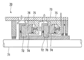
- FIG. 13 is a schematic longitudinal sectional view showing a dry gas seal structure 70 according to a conventional example.
- the dry gas seal structure 70 is composed of a rotating ring 72 fixed to a rotating shaft 71 and integrally rotating, and a stationary ring 74 provided in a housing 73 so as to face the rotating ring 72. Then, a spiral groove (not shown) is formed on the surface of the rotating ring 72, and the stationary ring 74 is urged toward the rotating ring 72 by the coil spring 75.
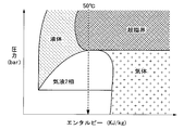
- FIG. 14 is a graph showing the relationship between the enthalpy of CO 2 and the pressure of CO 2 in the conventional dry gas seal structure 70.
- CO 2 accommodated in the housing 73 such as temperature pressure a 20MPa is supercritical state such as 30 ° C. or higher.
- the CO 2 adiabatically expands when passing through the seal gap 76, so that the CO at the exit portion of the seal gap 76.
- the temperature of 2 may be below freezing. In this case, moisture in the atmosphere may freeze around the outlet portion of the seal gap 76.
- the present invention has been made in consideration of such circumstances, and its purpose is to start driving the rotating shaft even when applied to a rotating machine in which a fluid in a supercritical state is accommodated inside the housing. It is an object of the present invention to provide a dry gas seal structure that does not sometimes cause problems in the seal gap.
- a first aspect of a dry gas seal structure includes a housing that contains a fluid in a supercritical state, a rotating shaft that is provided through the housing and is driven to rotate, and that surrounds the rotating shaft.
- a rotating ring that rotates integrally therewith, and is provided in the housing, contacts the rotating ring all around when the rotating shaft is stopped, and a seal gap is formed between the rotating ring and the rotating ring when the rotating shaft rotates.
- a stationary ring that is stationary in an open state, a pipe that supplies a part of the fluid contained in the housing to the inlet portion of the seal gap, and a temperature control device that adjusts the temperature of the fluid flowing through the pipe And a controller that controls the operation of the temperature control device so that the inlet portion of the seal gap is heated to a predetermined temperature before driving the rotating shaft.
- the supercritical fluid heated by the temperature control device is supplied before the driving of the rotating shaft, whereby the inlet portion of the seal gap is heated to a predetermined temperature in advance.
- a circulation pump that circulates the fluid supplied to the inlet portion of the seal gap and supplies the fluid to the inlet portion of the seal gap is provided in the pipe line. May be.
- the temperature control device includes a heater that heats the fluid flowing through the piping, and the heat source of the heater is the circulation pump or the rotating shaft. Any of the oil pumps for lubrication which supplies lubricating oil with respect to the bearing which supports can rotate freely may be sufficient.
- a second aspect of the dry gas seal structure according to the present invention is a housing that contains a fluid in a supercritical state, a rotary shaft that is provided to pass through the housing and is driven to rotate, and that surrounds the rotary shaft.
- a rotating ring that rotates integrally therewith, and is provided in the housing, contacts the rotating ring all around when the rotating shaft is stopped, and a seal gap is formed between the rotating ring and the rotating ring when the rotating shaft rotates.
- a stationary ring that is stationary in an opened state, a heater provided in at least one of the rotating ring and the stationary ring, and an inlet portion of the seal gap are heated to a predetermined temperature before driving the rotating shaft.
- the entrance portion of the seal gap is heated in advance to a predetermined temperature by the heater provided in the rotating ring or stationary ring before the driving of the rotating shaft is started. Further, since it is not necessary to install a temperature control device for adjusting the temperature of the fluid outside the housing, it is possible to save space as the entire rotating machine.
- a third aspect of the dry gas seal structure according to the present invention includes a housing that contains a fluid in a supercritical state, a rotary shaft that is provided through the housing and is driven to rotate, and that surrounds the rotary shaft.
- a rotating ring that rotates integrally therewith, and is provided in the housing, contacts the rotating ring all around when the rotating shaft is stopped, and a seal gap is formed between the rotating ring and the rotating ring when the rotating shaft rotates.
- a stationary ring that is stationary in an open state, a heater provided immediately before the seal gap in the housing, and an inlet portion of the seal gap is heated to a predetermined temperature before driving the rotating shaft.
- a control unit for controlling the operation of the heater.
- the inlet portion of the seal gap is heated in advance to a predetermined temperature by the heater provided in the housing before the driving of the rotary shaft is started. Further, since it is not necessary to install a temperature control device for adjusting the temperature of the fluid outside the housing, it is possible to save space as the entire rotating machine.
- the flow passage formed inside the housing and through which the fluid in the supercritical state flows has a portion immediately before the seal gap as compared to other portions. It may be formed narrow.
- the inlet portion of the seal gap is heated by the stirring loss when the fluid flows through the narrow portion of the flow passage. Therefore, the temperature control device and the heater used for heating the inlet portion of the seal gap before the start of driving can be stopped after the driving of the rotary shaft is started. Therefore, the cost can be reduced because the running cost of the temperature control device and the heater becomes unnecessary.
- the inlet portion of the seal gap is heated in advance before starting the driving of the rotary shaft, so the temperature of the fluid in the supercritical state that passes through the seal gap at the start of driving of the rotary shaft. Becomes higher. Therefore, when the fluid in the supercritical state is depressurized when passing through the seal gap, the fluid changes from the supercritical state to the gas state. As a result, the physical properties of the fluid do not change abruptly and the behavior of the stationary ring remains stable.
- the temperature of the fluid passing through the seal gap at the start of driving the rotary shaft increases, so the viscosity of the fluid decreases. As a result, the amount of viscous heat generated when the fluid passes through the seal gap is reduced, and thermal deformation does not occur in the stationary ring or the like.
- the temperature of the fluid passing through the seal gap becomes high at the start of driving the rotary shaft, even if the fluid adiabatically expands when passing through the seal gap, the temperature of the fluid falls below freezing point at the exit portion of the seal gap. Can be prevented. Thereby, the water
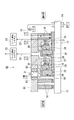
- FIG. 1 is a schematic longitudinal sectional view showing a dry gas seal structure according to a first embodiment of the present invention. It is a schematic diagram showing the structure of a CO 2 circulation system. It is a schematic diagram which shows the structure of a leak discharge system. It is a flowchart showing a flow of processing at the time of startup in CO 2 injection pump having a dry gas seal structure according to a first embodiment of the present invention. It is a flowchart showing a flow of processing at the time of startup in CO 2 injection pump having a dry gas seal structure according to a first embodiment of the present invention.
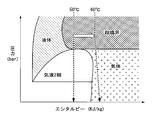
- An explanatory diagram for explaining the operation and effect of heating the seal gap before start of driving the rotating shaft is a graph taken on the vertical axis the pressure of CO 2 the enthalpy of CO 2 in the horizontal axis.
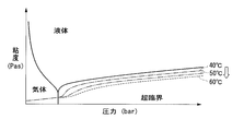
- An explanatory diagram for explaining the operation and effect of heating the seal gap before start of driving the rotating shaft is a graph taken on the vertical axis the viscosity of the CO 2 pressure of CO 2 in the horizontal axis.
- FIG. 1 is a schematic longitudinal sectional view showing a dry gas seal structure 10 of the present embodiment.
- the dry gas seal structure 10 includes a housing 12, a rotary shaft 13, a bearing 14, a lubricating oil pump 15, a first seal structure 16 and a second seal structure 17, an inboard labyrinth 18, and an outboard labyrinth 19. And a CO 2 circulation system 21 and a leak discharge system 23.
- a plurality of flow paths 11 are formed in the housing 12.
- the rotary shaft 13 is provided through the housing 12, is rotatably supported by the bearing 14, and is driven to rotate.
- the lubricating oil pump 15 supplies lubricating oil to the bearing 14.
- the first seal structure 16 and the second seal structure 17 are provided along the rotation shaft 13.
- Two in-machine labyrinths 18 are provided on the inside of the machine from the first seal structure 16 of the housing 12, and two out-of-machine labyrinths 19 are provided on the outside of the machine from the second seal structure 17 of the housing 12.
- the CO 2 circulation system 21 is connected to the housing 12 inside the machine from the first seal structure 16 via the circulation pipe line 20, and the leak discharge system 23 is outside the machine from the first seal structure 16 via the discharge pipe line 22.
- the housing 12 is connected.
- the housing 12 constitutes a wall surface of the CO 2 injection pump.
- the housing 12 contains CO 2 (carbon dioxide) in a supercritical state.
- a first flow path 11 ⁇ / b> A is formed in the middle of the two in-machine labyrinths 18, and a second flow path 11 ⁇ / b> B is formed in a position on the in-machine side from the first seal structure 16.
- a third flow path 11C is formed at a position on the outer side of the structure 16.
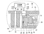
- the first seal structure 16 has a rotating ring 25, a coil spring 27, a stationary ring 28, and an O-ring 29.
- the rotary ring 25 is fixed to a shaft sleeve 24 that rotates integrally with the rotary shaft 13.
- One end of the coil spring 27 is attached to a retainer 26 fixed to the housing 12.
- the stationary ring 28 is fitted in a concave groove formed in the retainer 26, and the other end of the coil spring 27 is attached.
- the O-ring 29 is provided in various places to seal the position where the rotary ring 25 is attached to the shaft sleeve 24 and the position where the stationary ring 28 is attached to the retainer 26.
- a spiral groove is formed on the seal surface 25 a of the rotating ring 25, that is, the surface facing the stationary ring 28.
- a spiral groove may be formed on the seal surface 28 a of the stationary ring 28, that is, the surface on the side facing the rotating ring 25.
- the first seal structure 16 configured as described above, when the rotation of the rotating shaft 13 is stopped, the sealing surface 28a of the stationary ring 28 is changed to the sealing surface 25a of the rotating ring 25 by the biasing force of the coil spring 27. Close contact with. Thereby, the first seal structure 16 seals the space between the rotary shaft 13 and the housing 12 so that CO 2 in the machine does not leak out of the machine.
- CO 2 in the machine is introduced into a spiral groove (not shown) formed on the seal surface 25a of the rotating ring 25, and the rotating ring 25 is caused by the dynamic pressure effect. And a small seal gap 30 is formed between the stationary ring 28 and the stationary ring 28.
- the second seal structure 17 is for preventing a small amount of CO 2 that has passed through the seal gap 30 of the first seal structure 16 from leaking out of the machine other than the leak discharge system 23 as described above. . Since the configuration of the second seal structure 17 is the same as that of the first seal structure 16, the same reference numerals as those of the first seal structure 16 are used, and the description thereof is omitted. According to the second seal structure 17 constituted, among the small amount of CO 2 which has passed through the seal gap 30 of the first seal structure 16, further part of the CO 2 is the sealing gap of the second seal structure 17 By passing 30, most of the remaining CO 2 is prevented from leaking out of the machine. A small amount of the CO 2 that has passed through the first seal structure 16 is discharged outside the apparatus through the third flow path 11C.
- the second seal structure 17 replaces the seal function of the first seal structure 16 as a backup.
- a so-called tandem structure is provided by providing the second seal structure 17 in addition to the first seal structure 16.
- the second seal structure 17 is not an essential component of the present invention. It is good also as a structure provided with the structure 16 only.
- the in-machine labyrinth 18 and the out-of-machine labyrinth 19 are so-called labyrinth seals used for sealing compressed gas.
- the in-machine labyrinth 18 and the out-of-machine labyrinth 19 alternately form narrow portions and wide portions between the rotary shaft 13 and the housing 12. According to such a configuration, the CO 2 pressure expands in the widened portion after the in-machine CO 2 passes through the narrow portion, so that a pressure drop occurs in the CO 2 , and the leaked gas gradually decreases by repeating this. It has become.
- a leak discharge system 23 is also connected to the fourth flow path 11 ⁇ / b> D provided between the second seal structure 17 and the outboard labyrinth 19 via the discharge pipe line 22.
- the in-machine labyrinth 18 and the out-of-machine labyrinth 19 are not indispensable components for the present invention, but may be installed on the inside of the first seal structure 16 and the outside of the second seal structure 17 as in the present embodiment. There are the following merits.
- the CO 2 circulation system 21 is for supplying repeatedly cabin CO 2 with respect to the sealing gap 30 generated between the rotary ring 25 circulates cabin CO 2 and the stationary ring 28.
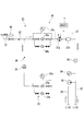
- FIG. 2 is an explanatory diagram showing a configuration of the CO 2 circulation system 21.
- the CO 2 circulation system 21 has a supply pipe extending from the inside of the machine to a predetermined location of a circulation pipe line 20 having one end connected to the first flow path 11A of the housing 12 shown in FIG. 1 and the other end connected to the second flow path 11B.
- One end of the path 32 is connected, and various components are installed at various locations of the circulation piping 20 and the supply piping 32.
- the circulation piping 20 has a CO 2 flow indicated by an arrow in the figure from the connection point to the first flow path 11 ⁇ / b> A to the connection point to the second flow path 11 ⁇ / b> B.
- a first filter unit 33, a circulation pump 34, a check valve 35, a second filter unit 36, a temperature control device 37, a flow meter 38, a pressure gauge 39, and a thermometer 40 are installed in this order.
- the first filter unit 33 is installed in the circulation pipeline 20 to remove foreign matter from CO 2 , a preliminary filter 33b that functions in a preliminary manner when the filter 33a is clogged, and the filter 33a. And a differential pressure gauge 33c for measuring the pressure difference between the upstream position and the downstream position.
- the second filter unit 36 also includes a filter 36 a, a spare filter 36 b, and a differential pressure gauge 36 c, and the function of each component is the same as that of each component of the first filter unit 33.
- the circulation pump 34 forcibly circulates CO 2 along the circulation pipeline 20.
- the check valve 35 is a valve having a function of keeping the flow of CO 2 in the circulation pipeline 20 constant at all times and preventing backflow.
- the temperature control device 37 arbitrarily adjusts the temperature of CO 2 flowing through the circulation pipeline 20.
- the temperature control device 37 includes a heat exchanger 37a that lowers the temperature of CO 2 by exchanging heat with cooling water, and a heater that heats CO 2 and raises its temperature. 37b.
- the operation of the temperature control device 37 is controlled by the control unit C.
- the control unit C controls not only the operation of the temperature control device 37 but also the operation of each part constituting the dry gas seal structure 10.
- the heater 37b may use a component provided in the dry gas seal structure 10 for another purpose as a heat source.
- the circulating pump loss generated in the circulating pump 34 or the lubricating oil pump loss generated in the lubricating oil pump 15 shown in FIG. 1 is converted into thermal energy, and this thermal energy is used as a heat source for the heater 37b. May be.
- the heat source of the heater 37b is not limited to the circulation pump 34 and the lubricating oil pump 15, and various pumps installed in the dry gas seal structure 10 can be used for other purposes. According to such a configuration, as compared with the case where the dedicated heater 37b is provided, there is an advantage that the cost can be reduced because the dedicated heat source is unnecessary and the running cost is not required.
- the heat exchanger 37a is not indispensable as a structure of the temperature control apparatus 37, and the temperature control apparatus 37 should just have the heater 37b at least.
- the flow meter 38 measures the flow rate of CO 2 circulating through the circulation pipeline 20.
- the pressure gauge 39 measures the pressure of CO 2 in the vicinity of the connection point to the second flow path 11B.
- the temperature gauge 40 is to measure the temperature of the CO 2 in the vicinity of the connection into the second flow path 11B.
- a pressure regulating valve 41 and a check valve 42 are installed in the supply pipe line 32 in order in the CO 2 flow direction.
- the pressure adjustment valve 41 is a valve that can arbitrarily adjust the supply pressure of CO 2 by adjusting the degree of opening and closing of the supply piping 32.
- the check valve 42 is a valve having a function of always maintaining the flow of CO 2 in the supply piping 32 in a certain direction and preventing backflow, and CO 2 circulating through the circulation piping 20 is supplied to the supply piping 32. Prevents inflow.
- the leak discharge system 23 is for discharging a small amount of CO 2 that has passed through the seal gap 30 of the first seal structure 16 to the outside of the apparatus.
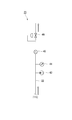
- FIG. 3 is a schematic diagram showing the configuration of the leak discharge system 23.
- a discharge pipe line 22 having one end connected to the third flow path 11 ⁇ / b> C of the housing 12 shown in FIG. 1 is drawn out to the outside of the apparatus, and various components are installed in various places of the discharge pipe line 22. It is a thing.
- thermometer 43 As shown in FIG. 3, a thermometer 43, a pressure gauge 44, a flow meter 45, and a back pressure valve 46 are installed in the discharge pipe line 22 in order from the third flow path 11 ⁇ / b > C toward the CO 2 flow direction.
- the thermometer 43 measures the temperature of CO 2 in the vicinity of the connection location to the third flow path 11C shown in FIG. Further, the pressure gauge 44 measures the pressure of CO 2 in the vicinity of the connection location to the third flow path 11C.
- the flow meter 45 measures the flow rate of CO 2 flowing through the discharge pipe line 22.
- the back pressure valve 46 is a valve for keeping the pressure of CO 2 upstream from itself constant. That is, when the upstream pressure becomes equal to or higher than the set value, the back pressure valve 46 keeps the upstream pressure constant by reducing the pressure through CO 2 .
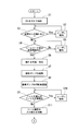
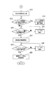
- 4 and 5 are flowcharts showing the flow of processing performed by the control unit C included in the CO 2 injection pump at startup.
- the control unit C supplies CO 2 in a gas state to the supply piping 32 (S1). Then, it is determined whether or not there is leakage of CO 2 gas from various places of the piping, specifically, the circulation piping path 20, the supply piping path 32, and the discharge piping path 22 (S2). As a result, when it is determined that there is a leakage of CO 2 gas (S2: Yes), this is notified to the user (S3), and it waits until there is no leakage. The user who has received the notification determines whether or not there is a CO 2 gas leak by, for example, determining whether or not bubbles are produced by applying soapy water to the joint portion of the pipe. Specific means for notifying the user includes a method of displaying a warning on a display screen and a method of generating a warning sound from a speaker, although details are not shown in the figure.
- the control unit C determines whether the seal leak amount is within an allowable range (S4). That is, the control unit C detects the measurement value of the flow meter 45 installed in the discharge pipe line 22 shown in FIG. 3, thereby causing the amount of seal leak, that is, CO 2 leaking from the seal gap 30 of the first seal structure 16. Detect the amount of. Then, it is determined whether or not the detected seal leak amount is within a range allowable as the seal leak amount in a state where the rotation of the rotary shaft 13 is stopped.
- the control unit C notifies the user (S5) and waits until the seal leak amount falls within the allowable range. In this case, there is a possibility that CO 2 is leaking from the stationary ring 28, the rotating ring 25 or the like. Take appropriate measures such as replacement.
- the control unit C proceeds to the next step.
- control unit C raises the temperature of the machine until the circulation pump 34 installed in the circulation pipeline 20 shown in FIG. 2 can be activated, specifically until the CO 2 in the machine reaches a supercritical state.
- the pressure is increased (S6).
- control unit C activates the circulation pump 34 (S7).
- control unit C detects the measurement value of the flow meter 38 installed in the circulation pipeline 20 shown in FIG. 2, and the circulation pump 34 so that the flow rate of CO 2 circulating through the circulation pipeline 20 becomes a predetermined flow rate. Is appropriately adjusted (S8).
- CO 2 flowing from the circulation pipe line 20 to the second flow path 11B is also on the inlet side of the sealing gap 30 of the first seal structure 16, inboard Since a sufficient amount also flows on the labyrinth 18 side, the inlet portion of the seal gap 30 can be sufficiently heated as will be described later, and foreign matter or the like enters from the inboard labyrinth 18 side toward the first seal structure 16. Can be prevented.
- the control unit C detects the measured values of the differential pressure gauges 33c and 36c of the first filter unit 33 and the second filter unit 36 installed in the circulation pipe line 20 shown in FIG. The pressure difference between the upstream side and the downstream side is detected across the filters 33a and 36a. Then, it is determined whether or not the detected filter differential pressure has reached a predetermined filter exchange differential pressure (S9). As a result, when it is determined that the filter differential pressure has reached the filter replacement differential pressure (S9: Yes), the control unit C displays on a display screen (not shown) to indicate that the filter 33a should be replaced. The user is notified (S10) and waits until the filter differential pressure falls below the filter exchange differential pressure. The user who has received the notification performs appropriate measures such as switching to the spare filters 33b and 36b or replacing the filters 33a and 36a with new ones.
- the controller C determines that the filter differential pressure has not yet reached the filter replacement differential pressure (S9: No)
- the controller C subsequently heats the inlet portion of the seal gap 30 of the first seal structure 16 to a predetermined temperature. (S11). That is, the control unit C controls the temperature adjustment device 37 shown in FIG. 2 so that the inlet portion of the seal gap 30 of the first seal structure 16 is heated to CO 2 flowing from the second flow path 11B and reaches a predetermined temperature.
- the operation of the heat exchanger 37a and the heater 37b to be configured is controlled.
- the “inlet portion of the seal gap 30” means the vicinity of the most upstream portion of the seal gap 30 in the CO 2 flow direction, and the rotating ring 25, the stationary ring 28, the shaft sleeve 24, and the retainer. 26 and the housing 12 are included.
- FIG. 6 and FIG. 7 are explanatory diagrams for explaining the effect of heating the inlet portion of the seal gap 30.
- the temperature of CO 2 when passing through the seal gap 30 rises.
- the temperature of CO 2 is increased, for example, from 50 ° C. to 60 ° C.
- the CO 2 is decompressed during passage of the sealing gap 30, the state of the CO 2 is to the gaseous state from the supercritical state And change. Therefore, the physical properties of CO 2 do not change drastically compared with the case where the gas phase changes from the supercritical state to the gas-liquid two phase as described above. Accordingly, the behavior of the stationary ring 28 remains stable.
- FIG. 6 shows that shows that the temperature of CO 2 is increased, for example, from 50 ° C. to 60 ° C.
- the CO 2 is decompressed during passage of the sealing gap 30
- the state of the CO 2 is to the gaseous state from the supercritical state And change. Therefore, the physical properties of CO 2 do not change drastically compared with the case where the gas phase changes from
- control unit C increases the supply pressure of CO 2 to a predetermined pressure (S12). That is, the control part C raises the supply pressure of CO 2 by controlling the operation of the pressure regulating valve 41 installed in the supply pipeline 32 shown in FIG.
- the control unit C together with this, CO 2 in the seal at the inlet portion of the gap 30 so that CO 2 is a predetermined pressure, the outlet portion of the sealing gap 30 of the first seal structure 16 of the second seal structure 17 Is controlled by controlling the operation of the back pressure valve 46 installed in the discharge pipe line 22.
- the control unit C determines whether or not the temperature of the outlet portion of the seal gap 30 of the first seal structure 16 is below freezing (S13). That is, the control unit C detects the temperature of the outlet portion of the seal gap 30 of the first seal structure 16 by detecting the measurement value of the thermometer 43 installed in the discharge pipe line 22 shown in FIG. When the detected temperature is below freezing (S13: Yes), the control unit C further heats the inlet portion of the seal gap 30 (S14). That is, the control unit C is configured to adjust the temperature control device shown in FIG. 2 so that the inlet portion of the seal gap 30 of the first seal structure 16 is heated by CO 2 flowing from the second flow path 11B and the temperature thereof further increases. The operation of 37 is controlled.
- the temperature of the inlet portion of the seal gap 30 of the first seal structure 16 is prevented from becoming below freezing point, moisture in the atmosphere will not freeze at the outlet portion of the seal gap 30. If the temperature of the CO 2 cannot be further increased due to the performance of the temperature control device 37, details are not shown in the figure, but the gas heated to the outlet portion of the seal gap 30 of the first seal structure 16 is not shown. For example, the outlet portion of the seal gap 30 may not be below freezing point by spraying.
- the controller C determines again whether or not the seal leak amount is within the allowable range (S15). That is, the control unit C detects the measurement value of the flow meter 45 installed in the discharge pipe line 22 shown in FIG. 3, thereby causing the amount of seal leak, that is, CO 2 leaking from the seal gap 30 of the first seal structure 16. Detect the amount of. Then, it is determined whether or not the detected seal leak amount is within a range allowable as the seal leak amount in a state where the rotation of the rotary shaft 13 is stopped. As a result, when it is determined that the seal leak amount is not within the allowable range (S15: No), the control unit C notifies the user (S16) and waits until the seal leak amount falls within the allowable range. The user who has received the notification performs appropriate measures so that the seal leak amount falls within the allowable range.
- the user when it is determined that the seal leak amount is outside the allowable range, particularly when the seal leak amount is zero, the user has the CO 2 air volume at the exit portion of the seal gap 30. Confirm whether or not.
- the user takes measures such as repair after finding the leaking portion.
- the supply of CO 2 is stopped, and it is confirmed whether or not the pressure inside the device decreases.
- the seal gap 30 may be closed, and thus a measure such as hand turning is performed.
- the user checks whether a failure has occurred in various sensors as other measures.
- the user inspects the rotary ring 25 and the stationary ring 28 and then performs measures such as repair and replacement. Apply.
- the control unit C starts rotation of the rotary shaft 13 by starting a motor (not shown), and the rotation speed is set to a predetermined speed. (S17). At this time, the control part C accelerates rapidly until the rotating shaft 13 reaches a predetermined minimum rotational speed or more. Further, as the rotational speed of the rotary shaft 13 increases, the temperature of the seal gap 30 increases due to CO 2 agitation loss or viscous heat generation in the seal gap 30. Therefore, the control unit C appropriately controls the operation of the temperature adjustment device 37 shown in FIG. 2 so that the temperature of the inlet portion of the seal gap 30 can be maintained at an appropriate temperature regardless of the temperature increase.
- control part C stops the operation
- the control unit C determines again whether or not the seal leak amount is within the allowable range (S18). That is, the control unit C detects the measurement value of the flow meter 45 installed in the discharge pipe line 22 shown in FIG. 3, thereby causing the amount of seal leak, that is, CO 2 leaking from the seal gap 30 of the first seal structure 16. Detect the amount of. Then, it is determined whether or not the detected seal leak amount is within a range allowed as the seal leak amount when the rotary shaft 13 is in a rotating state. As a result, when it is determined that the seal leak amount is not within the allowable range (S18: No), the control unit C notifies the user (S19) and waits until the seal leak amount falls within the allowable range. The user who has received the notification performs appropriate measures so that the seal leak amount falls within the allowable range.
- the control unit C detects the seal leak amount again, and the detected seal leak amount is allowed as the seal leak amount in a state where the rotation of the rotary shaft 13 is stopped. Check if it is inside.
- the user when it is determined that the seal leak amount is outside the allowable range, particularly when the seal leak amount is excessive, the user immediately stops the rotation of the rotary shaft 13 and inspects the rotary ring 25 and the stationary ring 28. Above, take measures such as repair and replacement.
- control unit C decreases the rotational speed of the circulation pump 34 installed in the circulation pipeline 20 shown in FIG. 2 and circulates CO 2 supplied from the inside of the machine through the circulation pipeline 20. And finally, the control part C stops the circulation pump 34 and performs rated operation (S20).
- FIG. 8 is a schematic longitudinal sectional view showing the dry gas seal structure 50 of the present embodiment.
- the dry gas seal structure 50 is different from the dry gas seal structure 10 of the first embodiment in that the configuration of the rotary ring 51 of the first seal structure 16 is different and the CO2 circulation system 21 is not provided. . Since the other configuration is the same as that of the first embodiment, the same reference numerals as those in FIG. 1 are used, and description thereof is omitted here.
- the rotary ring 51 of the first seal structure 16 houses a heater 52 therein, and the operation of the heater 52 is controlled by a control unit (not shown). Then, the control unit heats the inlet portion of the seal gap 30 of the first seal structure 16 to a predetermined temperature by turning on the heater 52 before starting the driving of the rotary shaft 13.
- a control unit not shown
- the control unit heats the inlet portion of the seal gap 30 of the first seal structure 16 to a predetermined temperature by turning on the heater 52 before starting the driving of the rotary shaft 13.
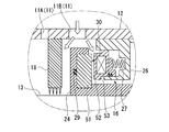
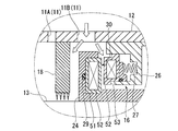
- FIG. 9A and FIG. 9B are diagrams showing a modification of the present embodiment.
- the heater 52 is accommodated inside the stationary ring 53.
- the heater 52 is accommodated in the rotating ring 51 and the heater 52 is accommodated in the stationary ring 53.
- the inlet portion of the seal gap 30 of the first seal structure 16 is heated to a predetermined temperature.
- the rotary ring 51 is generally made of silicon carbide, which is a material that is not easily thermally deformed, it is preferable to accommodate the heater 52 in the rotary ring 51 because thermal deformation can be suppressed. is there.
- FIG. 10 is a schematic longitudinal sectional view showing the dry gas seal structure 60 of the present embodiment.
- the dry gas seal structure 60 differs from the dry gas seal structure 10 of the first embodiment in that the configuration of the housing 61 is different and the CO 2 circulation system 21 is not provided. Since the other configuration is the same as that of the first embodiment, the same reference numerals as those in FIG. 1 are used, and description thereof is omitted here.
- a heater 62 is accommodated in the periphery of the second flow path 11B. And before starting the drive of the rotating shaft 13, this heater 62 is turned ON, and the entrance part of the seal gap 30 of the 1st seal structure 16 is heated to predetermined temperature. According to such a configuration, as in the second embodiment, there is an advantage that the space can be saved because the space for installing the CO 2 circulation system 21 outside the apparatus is unnecessary.
- FIG. 11 is a schematic longitudinal sectional view showing the dry gas seal structure 70 of the present embodiment, and is an enlarged view of the periphery of the seal gap 30.
- the dry gas seal structure 70 differs in the shape of the flow passage 71 formed between the second flow path 11B and the inlet portion of the seal gap 30. Since the other configuration is the same as that of the first embodiment, the same reference numerals as those in FIG. 1 are used, and description thereof is omitted here.
- the peripheral portion of the rotary ring 25 in the shaft sleeve 72 is formed with a larger diameter compared to the first embodiment.
- the flow passage 71 through which CO 2 flows inside the housing 12 is formed such that the portion immediately before the seal gap 30 of the first seal structure 16 is narrower than the other portions. According to such a configuration, it is necessary to heat the entrance portion of the seal gap 30 in the same manner as in the first to third embodiments before starting the driving of the rotating shaft 13, but after starting the driving of the rotating shaft 13. The temperature of the inlet portion of the seal gap 30 of the first seal structure 16 rises due to agitation loss when CO 2 passes through this narrow portion.
- the heaters 37b, 62, etc. used to heat the inlet portion of the seal gap 30 before the drive start can be turned off.
- the cost can be reduced by reducing the running cost of the heaters 37b and 62.
- FIG. 12 is a view showing a modification of the present embodiment.
- the peripheral portion of the second flow path 11B in the housing 73 is formed thicker than the other portions.
- the portion immediately before the seal gap 30 of the first seal structure 16 is formed narrower than the other portions.
- the present invention relates to a dry gas seal structure for sealing between a rotating shaft of a rotating machine and a housing. According to the present invention, the stationary ring can be kept in a stable state.
Landscapes
- Engineering & Computer Science (AREA)
- General Engineering & Computer Science (AREA)
- Mechanical Engineering (AREA)
- Mechanical Sealing (AREA)
- Structures Of Non-Positive Displacement Pumps (AREA)
Abstract
Description
ハウジング12には、複数の流路11が形成されている。回転軸13は、ハウジング12を貫通して設けられて軸受14に回転自在に支持され、回転駆動される。潤滑用油ポンプ15は、軸受14に潤滑油を供給する。第1シール構造16及び第2シール構造17は、回転軸13に沿って設けられている。機内側ラビリンス18は、ハウジング12の第1シール構造16より機内側に2個設けられ、機外側ラビリンス19は、ハウジング12の第2シール構造17より機外側に2個設けられている。CO2循環システム21は、循環配管路20を介して第1シール構造16より機内側のハウジング12に接続され、リーク排出システム23は、排出配管路22を介して第1シール構造16より機外側のハウジング12に接続されている。
ここで、図2は、CO2循環システム21の構成を示す説明図である。CO2循環システム21は、一端が図1に示すハウジング12の第1流路11Aに接続され他端が第2流路11Bに接続された循環配管路20の所定箇所に、機内から延びる供給配管路32の一端が接続され、循環配管路20と供給配管路32の各所に種々の構成要素が設置されたものである。
12…ハウジング
13…回転軸
20…循環配管路
25…回転環
28…静止環
30…シール隙間
37…温調装置
C…制御部
Claims (6)
- 超臨界状態の流体を収容するハウジングと、
該ハウジングを貫通して設けられ回転駆動される回転軸と、
該回転軸を包囲して設けられこれと一体的に回転する回転環と、
前記ハウジングに設けられ、前記回転軸の停止時に前記回転環と全周で当接し、前記回転軸の回転時に前記回転環との間にシール隙間を開けた状態で静止する静止環と、
前記シール隙間の入口部分に対し、前記ハウジングに収容された流体の一部を供給する配管路と、
前記配管路を流れる流体の温度を調節する温調装置と、
前記回転軸を駆動する前に、前記シール隙間の入口部分が所定温度まで加熱されるよう、前記温調装置の動作を制御する制御部と、
を備えるドライガスシール構造。 - 前記配管路に、前記シール隙間の入口部分に供給した流体を循環させて前記シール隙間の入口部分に再度供給する循環ポンプが設けられている請求項1に記載のドライガスシール構造。
- 前記温調装置が、前記配管路を流れる流体を加熱するヒータを備え、該ヒータの熱源が、前記循環ポンプ、または前記回転軸を回転自在に支持する軸受に対して潤滑油を供給する潤滑用油ポンプのいずれかである請求項2に記載のドライガスシール構造。
- 超臨界状態の流体を収容するハウジングと、
該ハウジングを貫通して設けられ回転駆動される回転軸と、
該回転軸を包囲して設けられこれと一体的に回転する回転環と、
前記ハウジングに設けられ、前記回転軸の停止時に前記回転環と全周で当接し、前記回転軸の回転時に前記回転環との間にシール隙間を開けた状態で静止する静止環と、
前記回転環及び前記静止環の少なくともいずれか一方に設けられたヒータと、
前記回転軸を駆動する前に、前記シール隙間の入口部分が所定温度まで加熱されるよう、前記ヒータの動作を制御する制御部と、
を備えるドライガスシール構造。 - 超臨界状態の流体を収容するハウジングと、
該ハウジングを貫通して設けられ回転駆動される回転軸と、
該回転軸を包囲して設けられこれと一体的に回転する回転環と、
前記ハウジングに設けられ、前記回転軸の停止時に前記回転環と全周で当接し、前記回転軸の回転時に前記回転環との間にシール隙間を開けた状態で静止する静止環と、
前記ハウジングにおける前記シール隙間の直前位置に設けられたヒータと、
前記回転軸を駆動する前に、前記シール隙間の入口部分が所定温度まで加熱されるよう、前記ヒータの動作を制御する制御部と、
を備えるドライガスシール構造。 - 前記ハウジングの内部に形成され前記超臨界状態の流体が流れる流通路は、前記シール隙間の直前部分がその他の部分より幅狭に形成されている請求項1乃至5のいずれか1項に記載のドライガスシール構造。
Priority Applications (5)
| Application Number | Priority Date | Filing Date | Title |
|---|---|---|---|
| PCT/JP2011/074768 WO2013061436A1 (ja) | 2011-10-27 | 2011-10-27 | ドライガスシール構造 |
| US13/638,950 US9791046B2 (en) | 2011-10-27 | 2011-10-27 | Rotary machine |
| AU2011372779A AU2011372779B2 (en) | 2011-10-27 | 2011-10-27 | Dry gas seal structure |
| CN201180021545.5A CN102959287B (zh) | 2011-10-27 | 2011-10-27 | 干气密封结构 |
| EP11864131.5A EP2772670B1 (en) | 2011-10-27 | 2011-10-27 | Dry gas seal structure |
Applications Claiming Priority (1)
| Application Number | Priority Date | Filing Date | Title |
|---|---|---|---|
| PCT/JP2011/074768 WO2013061436A1 (ja) | 2011-10-27 | 2011-10-27 | ドライガスシール構造 |
Publications (1)
| Publication Number | Publication Date |
|---|---|
| WO2013061436A1 true WO2013061436A1 (ja) | 2013-05-02 |
Family
ID=47766344
Family Applications (1)
| Application Number | Title | Priority Date | Filing Date |
|---|---|---|---|
| PCT/JP2011/074768 Ceased WO2013061436A1 (ja) | 2011-10-27 | 2011-10-27 | ドライガスシール構造 |
Country Status (5)
| Country | Link |
|---|---|
| US (1) | US9791046B2 (ja) |
| EP (1) | EP2772670B1 (ja) |
| CN (1) | CN102959287B (ja) |
| AU (1) | AU2011372779B2 (ja) |
| WO (1) | WO2013061436A1 (ja) |
Families Citing this family (30)
| Publication number | Priority date | Publication date | Assignee | Title |
|---|---|---|---|---|
| DE102010041210A1 (de) * | 2010-09-22 | 2012-03-22 | Siemens Aktiengesellschaft | Gehäuse |
| EP2820247B1 (de) * | 2012-03-02 | 2021-02-17 | Maag Pump Systems AG | Dichtungsanordnung, eine fördereinrichtung mit einer dichtungsanordnung sowie ein verfahren zum betrieb der dichtungsanordnung |
| US9395000B2 (en) * | 2014-08-19 | 2016-07-19 | Flowserve Management Company | Apparatus for excluding particle contaminants from a gas lift off mechanical seal |
| CA2962898C (en) * | 2014-09-29 | 2019-06-25 | New Way Machine Components, Inc. | Thrust bearing as a seal |
| ITUB20152676A1 (it) * | 2015-07-30 | 2017-01-30 | Nuovo Pignone Tecnologie Srl | Disposizione di raffreddamento di tenute a gas secco e metodo |
| CN105351244B (zh) * | 2015-11-24 | 2017-08-25 | 青海盐湖工业股份有限公司 | 串联式干气密封装置及其在轻烃泵上的应用和使用方法 |
| CN105909798A (zh) * | 2016-06-20 | 2016-08-31 | 成都通密封股份有限公司 | 超临界流体设备用干气密封 |
| CN106352094B (zh) * | 2016-08-18 | 2017-12-29 | 浙江工业大学 | 用于动静压型干气密封的静压气体迷宫节流调控机构 |
| CN109689396B (zh) * | 2016-09-12 | 2022-07-29 | Ntn株式会社 | 车轮用轴承装置 |
| CN108087556B (zh) * | 2016-11-23 | 2021-03-30 | 舍弗勒技术股份两合公司 | 盒式密封结构 |
| US11174869B1 (en) * | 2017-02-17 | 2021-11-16 | Mitsubishi Heavy Industries Compressor Corporation | Rotary machine |
| IT201700029982A1 (it) * | 2017-03-17 | 2018-09-17 | Nuovo Pignone Tecnologie Srl | Tenuta a gas |
| CN107654377A (zh) * | 2017-09-28 | 2018-02-02 | 上海齐耀螺杆机械有限公司 | 无油螺杆机的轴封装置 |
| US12092127B2 (en) | 2018-02-14 | 2024-09-17 | Ceco Environmental Ip Inc. | Tandem seal pump |
| US10563663B2 (en) * | 2018-04-06 | 2020-02-18 | Solar Turbines Incorporated | Nitrogen purge of compressor dry seal |
| CN108591476B (zh) * | 2018-04-23 | 2019-08-23 | 西安交通大学 | 一种适用于超临界工质的干气密封装置 |
| US11988219B2 (en) | 2019-02-25 | 2024-05-21 | Ihi Corporation | Sealing device and integrated pump |
| DE102019107454A1 (de) * | 2019-03-22 | 2020-09-24 | Atlas Copco Energas Gmbh | Axialausgleich - gestufte Wellenabdichtung |
| CN110792630B (zh) * | 2019-11-07 | 2020-09-01 | 南京工程学院 | 一种气冷式波纹管干气密封装置 |
| CN110725955A (zh) * | 2019-11-08 | 2020-01-24 | 成都一通密封股份有限公司 | 一种保护轴承箱的超临界co2专用安全密封结构 |
| CN111305915B (zh) * | 2019-12-10 | 2022-06-03 | 河南科技大学 | 超临界二氧化碳透平机及其主轴冷却系统 |
| CN111577400B (zh) * | 2020-04-29 | 2024-08-09 | 中国核动力研究设计院 | 干气耦合迷宫密封的超临界二氧化碳涡轮轴端密封方法及装置 |
| CN111749736B (zh) * | 2020-05-20 | 2021-11-30 | 中国核动力研究设计院 | 一种超临界二氧化碳透平干气密封失效保护装置及方法 |
| CN112228160B (zh) * | 2020-10-20 | 2021-06-18 | 北京前沿动力科技股份有限公司 | 一种超临界二氧化碳转子分段冷却及密封结构 |
| CN113137477A (zh) * | 2021-03-12 | 2021-07-20 | 浙江态能动力技术有限公司 | 一种低泄漏耐高温的超临界二氧化碳密封气体换热器 |
| CN114198502B (zh) * | 2022-01-04 | 2024-03-19 | 昆明理工大学 | 一种电池三元材料搅拌设备用镶装式聚四氟乙烯静压干气密封环及其制备方法与应用 |
| CN114753890B (zh) * | 2022-04-27 | 2023-10-24 | 重庆江增船舶重工有限公司 | 一种超临界二氧化碳透平的干气密封及其泄漏量监测方法 |
| EP4792046A1 (en) * | 2023-12-07 | 2026-08-19 | Siemens Energy Global GmbH & Co. KG | Gas seal cooling system |
| CN117646797B (zh) * | 2024-01-30 | 2024-05-14 | 中密控股股份有限公司 | 一种适用于舰船动力装置冷却剂循环泵用密封 |
| CN117704037B (zh) * | 2024-02-05 | 2024-04-12 | 中国核动力研究设计院 | 一种超临界二氧化碳零泄漏干气密封装置及方法 |
Citations (11)
| Publication number | Priority date | Publication date | Assignee | Title |
|---|---|---|---|---|
| JPS59147659A (ja) * | 1983-02-14 | 1984-08-24 | Mitsubishi Heavy Ind Ltd | 高炉炉頂から排出される高圧含じんガスからダストを捕集して大気圧雰囲気へ排出するための装置 |
| JPS6129166U (ja) * | 1984-07-27 | 1986-02-21 | 日本鋼管株式会社 | ガス漏洩防止用軸封装置 |
| JPS62147764U (ja) * | 1986-03-11 | 1987-09-18 | ||
| JPS638205A (ja) * | 1986-06-26 | 1988-01-14 | Teijin Ltd | 酸素富化器 |
| JPH03130968U (ja) * | 1990-04-17 | 1991-12-27 | ||
| JP2612673B2 (ja) * | 1993-12-01 | 1997-05-21 | 株式会社荏原製作所 | ポンプ装置 |
| JP2002013645A (ja) * | 2000-06-29 | 2002-01-18 | Nippon Pillar Packing Co Ltd | 液化ガス用軸封装置 |
| JP2003028094A (ja) * | 2001-06-27 | 2003-01-29 | Nuovo Pignone Holding Spa | 遠心圧縮機用のバランスピストン |
| JP2004190783A (ja) | 2002-12-11 | 2004-07-08 | Mitsubishi Heavy Ind Ltd | ドライガスシール式回転機械の起動方法およびドライガスシール式回転機械 |
| JP2011504136A (ja) * | 2007-11-12 | 2011-02-03 | エクソンモービル アップストリーム リサーチ カンパニー | ユーティリティガスの製造及び利用方法 |
| JP2011231880A (ja) * | 2010-04-28 | 2011-11-17 | Mitsubishi Heavy Ind Ltd | ドライガスシール構造 |
Family Cites Families (23)
| Publication number | Priority date | Publication date | Assignee | Title |
|---|---|---|---|---|
| JPS5290682A (en) | 1976-01-21 | 1977-07-30 | Hitachi Ltd | Shaft seal of fermentation tank |
| JPS58140632A (ja) | 1982-02-17 | 1983-08-20 | Hitachi Ltd | 核磁気共鳴を用いた検査装置 |
| JPS6129166A (ja) | 1984-07-19 | 1986-02-10 | Nec Corp | 機能トリミング方法 |
| US4661374A (en) | 1984-08-07 | 1987-04-28 | Texas Instruments Incorporated | Method of making MOS VLSI semiconductor device with metal gate and clad source/drain |
| JP2503406B2 (ja) | 1985-12-20 | 1996-06-05 | 日本電気株式会社 | 半導体装置の製造方法 |
| JPH02292579A (ja) | 1989-05-08 | 1990-12-04 | Hitachi Ltd | 軸封装置部の回転軸温度制御装置 |
| JP3269624B2 (ja) | 1989-07-17 | 2002-03-25 | 株式会社日立製作所 | 磁気ディスク装置、磁気ディスクおよびサーボライト装置 |
| US5147015A (en) * | 1991-01-28 | 1992-09-15 | Westinghouse Electric Corp. | Seal oil temperature control method and apparatus |
| JPH11107705A (ja) | 1997-10-07 | 1999-04-20 | Mitsubishi Heavy Ind Ltd | ガスタービンクリアランスのアクティブコントロール方法 |
| EP1008759A1 (en) * | 1998-12-10 | 2000-06-14 | Dresser Rand S.A | Gas compressor |
| JP3710702B2 (ja) * | 2000-11-14 | 2005-10-26 | イーグル工業株式会社 | タンデムシール |
| JP2002267027A (ja) * | 2001-03-12 | 2002-09-18 | Mitsubishi Heavy Ind Ltd | 軸封装置 |
| JP2003074714A (ja) * | 2001-08-31 | 2003-03-12 | Eagle Ind Co Ltd | メカニカルシール装置 |
| JP3960176B2 (ja) * | 2001-10-29 | 2007-08-15 | 株式会社デンソー | 回転式ポンプ及び回転式ポンプを備えたブレーキ装置 |
| US6715985B2 (en) | 2002-05-15 | 2004-04-06 | John Crane Inc. | Gas conditioning system |
| EP1577561A1 (de) * | 2004-03-19 | 2005-09-21 | MAN Turbomaschinen AG Schweiz | Umwälz- und Heizvorrichtung für einen Rotationskompressor |
| DE102005015212A1 (de) * | 2005-04-02 | 2006-10-05 | Leybold Vacuum Gmbh | Wellendichtung |
| US7588612B2 (en) * | 2005-07-19 | 2009-09-15 | Bank Of America, N.A. | Mobile nitrogen generation device |
| JP4642788B2 (ja) | 2007-01-22 | 2011-03-02 | 株式会社荏原製作所 | 多段高圧ポンプ |
| US8585060B2 (en) * | 2007-11-20 | 2013-11-19 | Eagle Industry Co., Ltd. | Tandem seal device |
| US8186688B2 (en) * | 2008-02-25 | 2012-05-29 | Eagle Industry Co., Ltd. | Shaft sealing device |
| WO2009143213A2 (en) | 2008-05-21 | 2009-11-26 | John Crane Inc. | Seal monitoring and control system |
| US8790531B2 (en) * | 2011-07-08 | 2014-07-29 | Alvin Gabriel Stern | High purity, environmentally clean method and apparatus, for high rate, liquid anisotropic etching of single crystal silicon or etching of polycrystalline silicon, using an overpressure of ammonia gas above aqueous ammonium hydroxide |
-
2011
- 2011-10-27 EP EP11864131.5A patent/EP2772670B1/en active Active
- 2011-10-27 AU AU2011372779A patent/AU2011372779B2/en not_active Ceased
- 2011-10-27 CN CN201180021545.5A patent/CN102959287B/zh active Active
- 2011-10-27 WO PCT/JP2011/074768 patent/WO2013061436A1/ja not_active Ceased
- 2011-10-27 US US13/638,950 patent/US9791046B2/en not_active Expired - Fee Related
Patent Citations (11)
| Publication number | Priority date | Publication date | Assignee | Title |
|---|---|---|---|---|
| JPS59147659A (ja) * | 1983-02-14 | 1984-08-24 | Mitsubishi Heavy Ind Ltd | 高炉炉頂から排出される高圧含じんガスからダストを捕集して大気圧雰囲気へ排出するための装置 |
| JPS6129166U (ja) * | 1984-07-27 | 1986-02-21 | 日本鋼管株式会社 | ガス漏洩防止用軸封装置 |
| JPS62147764U (ja) * | 1986-03-11 | 1987-09-18 | ||
| JPS638205A (ja) * | 1986-06-26 | 1988-01-14 | Teijin Ltd | 酸素富化器 |
| JPH03130968U (ja) * | 1990-04-17 | 1991-12-27 | ||
| JP2612673B2 (ja) * | 1993-12-01 | 1997-05-21 | 株式会社荏原製作所 | ポンプ装置 |
| JP2002013645A (ja) * | 2000-06-29 | 2002-01-18 | Nippon Pillar Packing Co Ltd | 液化ガス用軸封装置 |
| JP2003028094A (ja) * | 2001-06-27 | 2003-01-29 | Nuovo Pignone Holding Spa | 遠心圧縮機用のバランスピストン |
| JP2004190783A (ja) | 2002-12-11 | 2004-07-08 | Mitsubishi Heavy Ind Ltd | ドライガスシール式回転機械の起動方法およびドライガスシール式回転機械 |
| JP2011504136A (ja) * | 2007-11-12 | 2011-02-03 | エクソンモービル アップストリーム リサーチ カンパニー | ユーティリティガスの製造及び利用方法 |
| JP2011231880A (ja) * | 2010-04-28 | 2011-11-17 | Mitsubishi Heavy Ind Ltd | ドライガスシール構造 |
Non-Patent Citations (1)
| Title |
|---|
| See also references of EP2772670A4 |
Also Published As
| Publication number | Publication date |
|---|---|
| CN102959287A (zh) | 2013-03-06 |
| AU2011372779A1 (en) | 2013-05-16 |
| US9791046B2 (en) | 2017-10-17 |
| AU2011372779B2 (en) | 2014-04-24 |
| CN102959287B (zh) | 2015-10-07 |
| US20130106062A1 (en) | 2013-05-02 |
| EP2772670A1 (en) | 2014-09-03 |
| EP2772670B1 (en) | 2017-06-14 |
| EP2772670A4 (en) | 2015-08-19 |
Similar Documents
| Publication | Publication Date | Title |
|---|---|---|
| JP5535749B2 (ja) | ドライガスシール構造 | |
| CN102959287B (zh) | 干气密封结构 | |
| EP2805024B1 (en) | Dry gas seal for supercritical co2 pump-high pressure buffer | |
| WO2020017635A1 (ja) | シールシステム、および該シールシステムを備えたポンプシステム | |
| AU2016280924B2 (en) | Expansion turbine device | |
| WO2001007791A1 (en) | Turbo fluid machinery and dry gas seal used for the machinery | |
| JP5859889B2 (ja) | 高温流体用メカニカルシール | |
| KR910008912A (ko) | 축밀봉재 냉각 방법 및 장치 | |
| CN111183271B (zh) | 膨胀涡轮 | |
| CN107614836B (zh) | 膨胀涡轮装置 | |
| JP3933586B2 (ja) | ポンプの軸受監視装置及びその方法 | |
| CN109442779B (zh) | 主轴机构及具有其的主轴冷却系统 | |
| JP2009215992A (ja) | 液体加圧ポンプの運転方法及びそのメカニカルシール | |
| JP7380303B2 (ja) | 発電設備の冷却装置 | |
| JP7413825B2 (ja) | 発電設備の冷却装置 | |
| JP2009250151A (ja) | 軸流タービンのスラスト低減装置 | |
| Karassik et al. | Diagnostics of Field Problems |
Legal Events
| Date | Code | Title | Description |
|---|---|---|---|
| WWE | Wipo information: entry into national phase |
Ref document number: 201180021545.5 Country of ref document: CN |
|
| WWE | Wipo information: entry into national phase |
Ref document number: 13638950 Country of ref document: US |
|
| REEP | Request for entry into the european phase |
Ref document number: 2011864131 Country of ref document: EP |
|
| WWE | Wipo information: entry into national phase |
Ref document number: 2011864131 Country of ref document: EP |
|
| 121 | Ep: the epo has been informed by wipo that ep was designated in this application |
Ref document number: 11864131 Country of ref document: EP Kind code of ref document: A1 |
|
| NENP | Non-entry into the national phase |
Ref country code: DE |
|
| NENP | Non-entry into the national phase |
Ref country code: JP |