WO2013061596A1 - 空気潤滑式船舶の空気供給装置 - Google Patents
空気潤滑式船舶の空気供給装置 Download PDFInfo
- Publication number
- WO2013061596A1 WO2013061596A1 PCT/JP2012/006856 JP2012006856W WO2013061596A1 WO 2013061596 A1 WO2013061596 A1 WO 2013061596A1 JP 2012006856 W JP2012006856 W JP 2012006856W WO 2013061596 A1 WO2013061596 A1 WO 2013061596A1
- Authority
- WO
- WIPO (PCT)
- Prior art keywords
- air
- path
- pressure
- flow rate
- supply device
- Prior art date
- Legal status (The legal status is an assumption and is not a legal conclusion. Google has not performed a legal analysis and makes no representation as to the accuracy of the status listed.)
- Ceased
Links
Images



Classifications
-
- B—PERFORMING OPERATIONS; TRANSPORTING
- B63—SHIPS OR OTHER WATERBORNE VESSELS; RELATED EQUIPMENT
- B63B—SHIPS OR OTHER WATERBORNE VESSELS; EQUIPMENT FOR SHIPPING
- B63B1/00—Hydrodynamic or hydrostatic features of hulls or of hydrofoils
- B63B1/32—Other means for varying the inherent hydrodynamic characteristics of hulls
- B63B1/34—Other means for varying the inherent hydrodynamic characteristics of hulls by reducing surface friction
- B63B1/38—Other means for varying the inherent hydrodynamic characteristics of hulls by reducing surface friction using air bubbles or air layers gas filled volumes
-
- B—PERFORMING OPERATIONS; TRANSPORTING
- B63—SHIPS OR OTHER WATERBORNE VESSELS; RELATED EQUIPMENT
- B63H—MARINE PROPULSION OR STEERING
- B63H21/00—Use of propulsion power plant or units on vessels
- B63H21/12—Use of propulsion power plant or units on vessels the vessels being motor-driven
- B63H21/14—Use of propulsion power plant or units on vessels the vessels being motor-driven relating to internal-combustion engines
-
- F—MECHANICAL ENGINEERING; LIGHTING; HEATING; WEAPONS; BLASTING
- F02—COMBUSTION ENGINES; HOT-GAS OR COMBUSTION-PRODUCT ENGINE PLANTS
- F02B—INTERNAL-COMBUSTION PISTON ENGINES; COMBUSTION ENGINES IN GENERAL
- F02B37/00—Engines characterised by provision of pumps driven at least for part of the time by exhaust
- F02B37/12—Control of the pumps
- F02B37/16—Control of the pumps by bypassing charging air
- F02B37/164—Control of the pumps by bypassing charging air the bypassed air being used in an auxiliary apparatus, e.g. in an air turbine
-
- Y—GENERAL TAGGING OF NEW TECHNOLOGICAL DEVELOPMENTS; GENERAL TAGGING OF CROSS-SECTIONAL TECHNOLOGIES SPANNING OVER SEVERAL SECTIONS OF THE IPC; TECHNICAL SUBJECTS COVERED BY FORMER USPC CROSS-REFERENCE ART COLLECTIONS [XRACs] AND DIGESTS
- Y02—TECHNOLOGIES OR APPLICATIONS FOR MITIGATION OR ADAPTATION AGAINST CLIMATE CHANGE
- Y02T—CLIMATE CHANGE MITIGATION TECHNOLOGIES RELATED TO TRANSPORTATION
- Y02T10/00—Road transport of goods or passengers
- Y02T10/10—Internal combustion engine [ICE] based vehicles
- Y02T10/12—Improving ICE efficiencies
-
- Y—GENERAL TAGGING OF NEW TECHNOLOGICAL DEVELOPMENTS; GENERAL TAGGING OF CROSS-SECTIONAL TECHNOLOGIES SPANNING OVER SEVERAL SECTIONS OF THE IPC; TECHNICAL SUBJECTS COVERED BY FORMER USPC CROSS-REFERENCE ART COLLECTIONS [XRACs] AND DIGESTS
- Y02—TECHNOLOGIES OR APPLICATIONS FOR MITIGATION OR ADAPTATION AGAINST CLIMATE CHANGE
- Y02T—CLIMATE CHANGE MITIGATION TECHNOLOGIES RELATED TO TRANSPORTATION
- Y02T70/00—Maritime or waterways transport
- Y02T70/10—Measures concerning design or construction of watercraft hulls
Definitions
- the present invention relates to an air supply device for an air-lubricated ship for reducing the frictional resistance of water along the outer surface of the bottom of the ship being navigated.
- the frictional resistance of water is generally applied to the submerged surface at the bottom of the ship.
- most of the hull resistance is occupied by frictional resistance generated by the relative flow of outside water at the bottom of the ship.
- the reduction of the hull frictional resistance by air lubrication that jets air around the hull to reduce the frictional resistance has a large energy saving effect and is an effective means for reducing CO 2 emission from the ship.
- large ocean-going vessels with deep drafts require a large amount of energy to send air to the bottom of the ship, and application of the air lubrication method using only the blower has a limit in obtaining an energy saving effect.
- a system utilizing pressurized air or exhaust gas around the supercharger of the main engine was considered.
- Patent Documents 1 and 2 propose an apparatus that uses scavenging gas that is pressurized air between an air cooler and a main machine.
- Patent Documents 3 and 4 propose an apparatus that uses exhaust gas from the main engine.
- pressure location of a supercharger is proposed.
- Patent Document 6 proposes an apparatus that utilizes pressurized air and / or exhaust gas between a supercharger and a main engine.
- Patent Document 7 proposes an apparatus that includes compressed gas providing means that is rotationally driven by exhaust gas, and that uses the compressed gas in the compressed gas providing means.
- Japanese Patent Laid-Open No. 11-348870 Japanese Patent Laid-Open No. 11-348871 Japanese Patent Laid-Open No. 11-348869 JP 2001-97276 A JP 2001-48082 A JP 2010-23631 A JP 2010-274905 A
- the pressurized air pressure (scavenging air pressure) supplied to the main engine by the supercharger is proportional to the main engine output. That is, it has a property that it is low when the main engine load is low and high when the main machine load is high. The same applies to the exhaust gas in that it is proportional to the main engine output.
- the draft of a ship changes with loading conditions. Therefore, when the main engine load is low due to full load or the like, the scavenging air pressure of the main engine becomes lower than the draft pressure, and there are cases where air lubrication cannot be applied.
- Patent Document 1 to Patent Document 7 no measures are taken to expand the range in which air lubrication can be applied to the gas pressure that varies depending on the output of the main engine or the draft pressure that varies depending on the loading state, and in consideration of energy efficiency. .
- the present invention relates to whether the pressurized air pressure supplied to the main engine by the supercharger fluctuates depending on the output of the main engine or the draft pressure fluctuates depending on the loading state.
- An object of the present invention is to provide an air supply device for an air-lubricated ship that can be pressurized and ejected. ADVANTAGE OF THE INVENTION According to this invention, the air supply apparatus of the air-lubricated ship which can improve an energy-saving effect with high energy efficiency can be provided.
- the air supply apparatus for an air lubricated ship according to claim 1 is an air supply apparatus for an air lubricated ship that jets air around the hull to reduce frictional resistance.
- a supercharger that supplies pressurized air; a take-out means for taking out a part of the pressurized air; a pressure-up means for further boosting the pressurized air taken out by the take-out means;
- the boosting air and / or the pressurized air is selected by selecting the boosting path and / or the bypass path by the path selecting means. It is characterized by being supplied and ejected around the hull.
- the bypass route when the bypass route is selected, air is blown out around the hull using the pressurized air supplied to the main engine, and when the boost route is selected.
- the air can be ejected around the hull using the pressurized air obtained by further increasing the pressure of the pressurized air by the pressure increasing means. That is, it is possible to select a case where the jetting is performed using only the pressurized air and a case where the jetting is performed using the pressurized air assisted by the booster.
- the pressurized air can be pressurized and ejected. Therefore, it is possible to realize an air-lubricated ship that has high energy efficiency and can improve the energy saving effect.
- the pressurized air said here shall also contain the pressurized exhaust gas after the air pressurized with the supercharger burned with the main machine.
- an air supply device for an air-lubricated ship comprising a plurality of boosting means, a boosting path, and a path selecting means, It is characterized by enabling supply.
- a plurality of pressure increasing means by switching a plurality of pressure increasing means, it is possible to increase the pressure of the pressurized air in accordance with the variation of the pressurized air pressure or the variation of the draft pressure. Therefore, energy efficiency and energy saving effect can be further enhanced.
- the air pressure supply device further includes an air suction means for sucking air from the atmosphere into the pressure increase means, and the air pressure from the atmosphere is increased. It is possible to supply it as a feature.
- air can be ejected around the hull using air from the atmosphere separately from the pressurized air. For example, when the draft pressure is low, Air can be supplied around the hull. Therefore, energy efficiency and energy saving effect can be further enhanced.
- the bypass selecting unit selects the bypass route, bypasses the boosting unit, and supplies the pressurized air from the bypass route.
- the present invention is characterized in that air from the atmosphere is boosted by controlling the air suction means and supplied from the pressure boosting path.
- pressurized air is supplied in the bypass route, and air from the atmosphere is supplied in the boost route. Therefore, the amount of air jetted around the hull can be increased to increase the friction reduction effect and further improve the energy saving effect.
- the pressurized air taken out by the take-out means is supplied from the compressor constituting the supercharger. It is the scavenging gas as a part of the pressurized air sent to. According to the fifth aspect of the present invention, by using the scavenging gas, the energy required for the boosting means can be reduced.
- an air supply device for an air-lubricated ship according to any one of the first to fifth aspects, wherein the draft detection means for detecting the draft of the hull, the route selection means, and the boosting means, And a control means for controlling the control, and the control means performs control based on the detection result of the draft detection means.
- the fluctuation of the draft pressure due to the loaded state can be detected by the draft detection means, and the control means performs the control according to the draft pressure so that the pressurized air and the pressure increase It becomes possible to supply air in an appropriate combination, and the conditions under which air lubrication can be applied can be set accurately. Therefore, it is possible to select an air supply method with high energy efficiency.
- the air supply device further includes load detection means for detecting the load of the main engine, and the control means is configured to detect the load on the load detection means. Control is performed.
- the fluctuation of the pressurized air pressure due to the output of the main engine can be detected by the load detecting means, and the control means performs control according to the pressurized air pressure. Therefore, it is possible to select an air supply method with high energy efficiency.
- the load detecting means is detection of a scavenging gas pressure of the supercharger.
- the fluctuation detection of the pressurized air pressure can be detected without a time lag, so that the control following the fluctuation of the load is performed. It can be performed. Therefore, energy efficiency can be improved.
- the flow rate of the pressurized air is adjusted between the supercharger and the boosting means. And a flow rate control valve.
- the flow rate adjusting valve by providing the flow rate adjusting valve, the flow rate fluctuation due to the influence of the operating state of the boosting means is mitigated, and the supply flow rate of the pressurized air from the supercharger to the main engine is stabilized. be able to. Accordingly, it is possible to prevent a decrease in energy efficiency of the main engine.
- a flow rate detection for detecting a flow rate of pressurized air from the supercharger to the boosting means.
- the apparatus further includes means.
- the flow rate control of the pressurized air can be stably performed by providing the flow rate detecting means.
- the present invention according to claim 11 is the air lubrication ship air supply device according to claim 10, wherein the flow rate control value is controlled by feeding back the detected flow rate value detected by the flow rate detecting means. .
- the flow rate control valve by controlling the flow rate control valve, it is possible to control to take out the pressurized air in accordance with the set flow rate, maintain the amount of pressurized air to the main engine appropriately, Can be effectively increased. Further, for example, when a trouble occurs in the pressure increasing means, the scavenging air pressure can be adjusted by the flow rate adjusting valve, so that the main engine is not affected by the trouble and the safety is high.
- an opening of the flow control valve or a flow rate detection value detected by a flow rate detection means is obtained. It is characterized in that the boosting means is controlled by feedback. According to this invention of Claim 12, a pressure
- a blower capable of controlling the rotational speed is used as the pressure increasing means.
- voltage rise adjustment by a blower can be performed according to the fluctuation
- the rotational speed of the blower is detected, and the detected rotational speed value is fed back to control the blower.
- the control since the control can be performed according to the rotational speed of the blower, the control can be performed without detecting the flow rate detecting means.
- the hull motion detection means for detecting the motion of the hull is further provided.
- the hull motion detection value is fed forward to control the flow rate control valve and / or the boosting means.
- the pressurized air pressure supplied to the main engine by the supercharger varies depending on the output of the main engine, and even if the draft pressure varies depending on the loading state, the pressurized air is The pressure can be increased and ejected. Therefore, it is possible to realize an air-lubricated ship that has high energy efficiency and can improve the energy saving effect.
- a change in pressurized air pressure can be achieved by switching the plurality of boosting means.
- the pressurized air can be boosted and ejected according to fluctuations in the draft pressure. Therefore, energy efficiency and energy saving effect can be further enhanced.
- the pressure increasing means further includes an air suction means for sucking air from the atmosphere
- the air from the atmosphere is used separately from the pressurized air. Air can be ejected around the hull. For example, when the draft pressure is low, air from the atmosphere can be supplied around the hull. Therefore, energy efficiency and energy saving effect can be further enhanced.
- the boosting means is bypassed and pressurized air is supplied from the bypass path, and the air suction means is controlled to boost the air from the atmosphere and supplied from the boosting path
- pressurized air is supplied, and air from the atmosphere is supplied in the pressure increase path. Therefore, the amount of air jetted around the hull can be increased to increase the friction reduction effect and further improve the energy saving effect.
- the pressurized air taken out by the take-out means is a scavenging gas as a part of the pressurized air sent from the compressor constituting the supercharger to the main engine, by using the scavenging gas, The energy required can be reduced.
- a draft detection means for detecting the draft of the hull, a control means for controlling the route selection means and the boosting means are further provided, and when the control means performs control based on the detection result of the draft detection means, The fluctuation of the draft pressure depending on the state can be detected by the draft detection means, and the control means performs control according to the draft pressure, so that the pressurized air and the pressurized air can be appropriately combined and supplied.
- the conditions under which lubrication can be applied can be set accurately. Therefore, it is possible to select an air supply method with high energy efficiency.
- load detection means for detecting the load of the main machine is further provided, and when the control means performs control based on the detection result of the load detection means, the load detection means detects fluctuations in the pressurized air pressure due to the output of the main machine.
- the control means performs control according to the pressurized air pressure. Therefore, it is possible to select an air supply method with high energy efficiency.
- the load detection means detects the scavenging gas pressure of the supercharger
- the fluctuation detection of the pressurized air pressure can be detected without a time lag by detecting the fluctuation due to the output of the main engine by the scavenging gas pressure. Therefore, it is possible to perform control following the load variation. Therefore, energy efficiency can be improved.
- the flow rate detection means can be provided to stably control the flow rate of the pressurized air. it can.
- the flow rate control value is controlled by feeding back the flow rate detection value detected by the flow rate detection means, by controlling the flow rate control valve, it is possible to control to take out the pressurized air amount according to the set flow rate. It is possible to appropriately maintain the pressurized air amount to the pressure and effectively increase the pressure increase by the pressure increasing means. Further, for example, when a trouble occurs in the pressure increasing means, the scavenging air pressure can be adjusted by the flow rate adjusting valve, so that the main engine is not affected by the trouble and the safety is high. In addition, for example, the flow rate is set so that the flow rate control valve does not fully open and the flow rate is set, and the flow rate control valve compensates for this in response to fluctuations in the boosting means to stabilize the flow rate. It is also possible.
- the boosting means when controlling the boosting means by feeding back the flow rate detection value detected by the opening degree of the flow rate control valve or the flow rate detecting means, the boosting means is controlled according to the set opening degree or flow rate to obtain a predetermined flow rate. be able to.
- a blower capable of controlling the rotation speed is used as the boosting means, it is possible to adjust the boosting by the blower according to the fluctuation of the pressurized air pressure or the draft pressure.
- blower speed when the blower speed is detected and the detected blow speed value is fed back to control the blower, it can be controlled by the blower speed, so control without detecting the flow rate detection means, etc. it can.
- a hull motion detection means for detecting the hull motion is further provided, and when the flow rate control valve and / or the boosting means are controlled by feeding forward the hull motion detection value of the hull motion detection means, the hull motion detection means is provided.
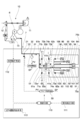
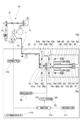
- FIG. 1 is a schematic configuration diagram of an air-lubricated ship equipped with an air supply device according to an embodiment of the present invention.
- Schematic configuration diagram of the air supply device of the same air lubricated ship showing a path for boosting the scavenging bypass gas and ejecting it from the air supply port
- Schematic configuration diagram of an air supply device of the same air-lubricated ship showing a path for ejecting the scavenging bypass gas from the air supply port without increasing the pressure
- Schematic configuration diagram of the air lubrication ship air supply device showing a path for ejecting scavenging bypass gas and air introduction air separately from the air supply port
- the horizontal axis is scavenging pressure (Ps)
- the vertical axis is draft pressure (Pd)
- Schematic configuration diagram of an air supply device according to another embodiment of an air-lubricated ship Schematic configuration diagram of an air supply device according to still another embodiment of an air-lubricated ship
- Air supply apparatus 10 Supercharger 21 Take-out route 22 Flow control valve 30a 1st pressure
- FIG. 1 is a schematic configuration diagram of an air-lubricated ship equipped with an air supply device according to an embodiment of the present invention.
- 2 to 4 are schematic configuration diagrams of the air supply device of the air lubricated ship.
- FIG. 2 shows a path for boosting the scavenging bypass gas and ejecting it from the air supply port.
- FIG. 3 shows a path through which the scavenging bypass gas is ejected from the air supply port without increasing the pressure.
- FIG. 4 shows paths through which scavenging bypass gas and air introduction air are separately ejected from the air supply port.
- the air-lubricated ship of the present embodiment includes an air supply device 7 (main part) on the bow 2 side of the hull 1 and a drive source 5 that drives a propeller on the stern 3 side.
- An air supply port 80 is provided on the bottom 4 of the bow 2.
- the air supply port 80 may be provided on the side of the bow near the ship bottom 4, the ship bottom 4 where the width of the hull 1 starts to narrow, or the side of the hull 1.
- the drive source 5 includes a main machine 6 that is an internal combustion engine, and a supercharger 10 that supplies pressurized air to the main machine 6 and is driven by exhaust gas from the main machine 6. Part of the pressurized air before being supplied to the main machine 6 is sent to the air supply device 7 through the take-out path 21.
- the air supply device 7 is provided with an air suction path 70 for sucking air from the air.
- the supercharger 10 includes a turbine 11 that extracts power from an exhaust path of the main engine 6, a compressor 12 that is operated by the turbine 11, and a scavenging receiver 13 that introduces air pressurized by the compressor 12 into a cylinder of the main engine 6. Have. One end of the extraction path 21 is connected to the scavenging receiver 13. The pressurized air is led from the scavenging receiver 13 to the extraction path 21. The other end of the take-out path 21 branches into three paths. A first on-off valve 61a, a second on-off valve 61b, and a third on-off valve 63 are provided at each path end.
- the extraction path 21 is provided with a flow rate adjusting valve 22 for adjusting the flow rate of the pressurized air and a flow rate detecting means 31 for detecting the flow rate of the pressurized air.
- the flow rate control valve 22 is PID controlled by feeding back the flow rate detection value detected by the flow rate detection means 31.
- the flow rate detection value detected by the flow rate detection means 31 is compared with the set value SP by the valve control unit 32, and the valve control unit 32 gives an operation signal to the flow rate control valve 22 so that the flow rate detection value approaches the set value SP. .
- the set value SP input to the valve control unit 32 sets an optimum flow rate according to, for example, the main engine output.
- the extraction means includes an extraction path 21, a flow rate adjustment valve 22, a flow rate detection means 31, and a valve control unit 32.
- the blower control unit 33 feeds back a flow rate detection value detected based on the opening degree of the flow rate control valve 22 to control the first booster 30a.
- the flow rate detection value detected by the flow rate control valve 22 is compared with the set value by the blower control unit 33, and the blower control unit 33 sets the rotation speed of the first booster 30a so that the flow rate detection value approaches the set value SP.
- the set value SP input to the blower control unit 33 is set to a constant value within a range of 80 to 95% of the valve opening, for example.
- the first pressure increasing path 41a has a first on-off valve 61a at one end and a fourth on-off valve 62a at the other end.
- the first pressure increasing path 41a is provided with first pressure increasing means 30a for further increasing the pressure of the pressurized air taken out by the extracting means.
- the first boosting path 41a supplies the boosted air boosted by the first boosting means 30a.
- the second pressure increasing path 41b has a second opening / closing valve 61b at one end and a fifth opening / closing valve 62b at the other end.
- the second pressure increasing path 41b is provided with second pressure increasing means 30b for further increasing the pressure of the pressurized air extracted by the extraction means.
- the second boosting path 41b supplies the boosted air boosted by the second boosting means 30b.
- the third on-off valve 63 is connected to a bypass path 51 that bypasses the first booster 30a and the second booster 30b.
- the path selection means for selecting the first pressure increasing path 41a and the bypass path 51 includes a first on-off valve 61a, a third on-off valve 63, and a fourth on-off valve 62a.
- the path selection means for selecting the second boost path 41b and the bypass path 51 includes a second on-off valve 61b, a third on-off valve 63, and a fifth on-off valve 62b.
- the route selection means may include a setting means for setting route selection and a control means for performing route selection control.
- a first atmospheric suction path 71a is connected to a first pressure increasing path 41a that connects the first on-off valve 61a and the first pressure increasing means 30a.
- the first atmospheric suction path 71a has one end opened to the atmosphere and the other end connected to the first boosting path 41a.
- the first atmospheric suction path 71a includes a sixth open / close valve 72a.
- a first atmospheric path 73a is connected to a first pressure increasing path 41a that connects the first pressure increasing means 30a and the fourth on-off valve 62a.
- the first atmospheric path 73a has one end connected to the first pressure increasing path 41a and the other end connected to the seventh on-off valve 74a.
- the atmospheric suction means for sucking air from the atmosphere into the first boosting means 30a includes a first atmospheric suction path 71a and a sixth on-off valve 72a.
- a second atmospheric suction path 71b is connected to a second pressure increasing path 41b connecting the second on-off valve 61b and the second pressure increasing means 30b.
- the second atmospheric suction path 71b has one end opened to the atmosphere and the other end connected to the second boost path 41b.
- the second air suction path 71b is provided with an eighth on-off valve 72b.
- a second atmospheric path 73b is connected to a second pressure increasing path 41b connecting the second pressure increasing means 30b and the fifth on-off valve 62b.
- the second atmospheric path 73b has one end connected to the second pressure increasing path 41b and the other end connected to the ninth on-off valve 74b.
- the atmospheric suction means for sucking air from the atmosphere into the second boosting means 30b includes a second atmospheric suction path 71b and an eighth on-off valve 72b.
- S1 starboard side supply port 81 S2 starboard side supply port 82, S3 starboard side supply port 83, P1 port side supply port 84, P2 port side supply port 85, and P3 port side. It consists of a supply port 86.
- An S1 supply path 91 is connected to the S1 starboard side supply port 81.
- An S2 supply path 92 is connected to the S2 starboard side supply port 82.
- An S3 supply path 93 is connected to the S3 starboard side supply port 83.
- a P1 supply path 94 is connected to the P1 port side supply port 84.
- a P2 supply path 95 is connected to the P2 port side supply port 85.
- a P3 supply path 96 is connected to the P3 port side supply port 86.
- An S1 on-off valve 101 is provided in the S1 supply path 91.
- An S2 opening / closing valve 102 is provided in the S2 supply path 92.
- An S3 opening / closing valve 103 is provided in the S3 supply path 93.
- a P1 opening / closing valve 104 is provided in the P1 supply path 94.
- a P2 opening / closing valve 105 is provided in the P2 supply path 95.
- a P3 opening / closing valve 106 is provided in the P3 supply path 96.
- the outflow side path of the fourth on-off valve 62a is branched into a plurality and connected to the S1 supply path 91, the S2 supply path 92, the S3 supply path 93, the P1 supply path 94, the P2 supply path 95, and the P3 supply path 96.
- the outflow side path of the fifth on-off valve 62b is branched into a plurality and connected to the S1 supply path 91, the S2 supply path 92, the S3 supply path 93, the P1 supply path 94, the P2 supply path 95, and the P3 supply path 96. ing.
- the outflow side path of the bypass path 51 is branched into a plurality, and is connected to the S1 supply path 91, the S2 supply path 92, the S3 supply path 93, the P1 supply path 94, the P2 supply path 95, and the P3 supply path 96.
- the outflow side path 75a of the seventh on-off valve 74a is connected to the S1 starboard side supply port 81.
- the outflow side path 75b of the ninth on-off valve 74b is connected to the P1 port side supply port 84.
- the air supply device 7 includes a control means 110 for controlling the take-out means, the route selection means, the first boosting means 30a, and the atmospheric suction means, the draft detection means 111 for detecting the draft of the hull 1, and the load on the main engine 6.
- Load detecting means 112 for detecting and hull motion detecting means 113 for detecting motion of the hull 1 are further provided.
- the load detection means 112 detects a load by the scavenging gas pressure of the supercharger 10, for example.
- the control unit 110 performs control based on at least one detection result of the draft detection unit 111, the load detection unit 112, and the hull motion detection unit 113.
- the hull motion detection value of the hull motion detection means 113 can be feedforward to control the flow rate control valve 22 and / or the first pressure boosting means 30a.
- the feedforward control predicts fluctuations such as drafts from the hull motion detection value, and controls the flow rate adjustment valve 22 or the first pressure boosting means 30a, thereby providing an air supply with a relatively slow response.
- the system can be controlled without response delay.
- control is performed roughly quickly with feedforward control, and fine adjustment is further performed with feedback control.
- FIG. 2 shows only the control related to the first booster 30a, but the second booster 30b can also be controlled with the same configuration.
- the blower control unit 33 can also serve as a control function.
- a blower capable of controlling the rotational speed.
- FIG. 2 shows a path for boosting the scavenging bypass gas and ejecting it from the air supply port.
- the pressurized air from the take-out path 21 is guided to the first boosting path 41a by the path selecting means and boosted by the first boosting means 30a. Thereafter, the pressurized air is guided to the S1 supply path 91, the S2 supply path 92, the P1 supply path 94, and the P2 supply path 95, and the S1 starboard side supply port 81, the S2 starboard side supply port 82, and the P1 port side supply port. 84 and the P2 port side supply port 85.
- the first on-off valve 61a and the fourth on-off valve 62a are opened, and the second on-off valve 61b, the third on-off valve 63, and the fifth on-off valve 62b are closed, thereby
- the pressurized air from the extraction path 21 is guided to the pressure increase path 41a.
- the sixth on-off valve 72a, the seventh on-off valve 74a, the eighth on-off valve 72b, and the ninth on-off valve 74b are closed.
- the pressurized air is ejected from the S1 starboard side supply port 81, the S2 starboard side supply port 82, the P1 port side supply port 84, and the P2 port side supply port 85, the S1 on-off valve 101, the S2 on-off valve 102, P1 The on-off valve 104 and the P2 on-off valve 105 are open, and the S3 on-off valve 103 and the P3 on-off valve 106 are closed.
- the route shown in FIG. 2 is effective when the main engine 6 has a low output at full load. That is, when the draft pressure is high at full load and the pressurized air pressure supplied to the main engine 6 is lowered, the frictional resistance is reduced by ejecting the pressurized air assisted by the first pressure increasing means 30a. Air can be blown out.
- the draft detection means 111 detects an increase in the draft pressure and the load detection means 112 detects a decrease in the pressurized air pressure
- the control means 110 causes the route selection means, other on-off valves, and the first pressure increase.
- the means 30a and the second boosting means 30b are controlled and the first boosting means 30a is assisted.
- FIG. 3 shows a path through which the scavenging bypass gas is ejected from the air supply port without increasing the pressure.
- the pressurized air from the extraction path 21 is guided to the bypass path 51 by the path selection means. Thereafter, the pressurized air is guided to the S1 supply path 91, the S2 supply path 92, the P1 supply path 94, and the P2 supply path 95, and the S1 starboard side supply port 81, the S2 starboard side supply port 82, and the P1 port side supply port. 84 and the P2 port side supply port 85.
- the first on-off valve 61a, the fourth on-off valve 62a, the second on-off valve 61b, and the fifth on-off valve 62b are closed, and the third on-off valve 63 is opened, thereby bypass path
- the pressurized air from the extraction path 21 is guided to 51.
- the sixth on-off valve 72a, the seventh on-off valve 74a, the eighth on-off valve 72b, and the ninth on-off valve 74b are closed.
- the pressurized air is ejected from the S1 starboard side supply port 81, the S2 starboard side supply port 82, the P1 port side supply port 84, and the P2 port side supply port 85, the S1 on-off valve 101, the S2 on-off valve 102, The P1 on-off valve 104 and the P2 on-off valve 105 are opened, and the S3 on-off valve 103 and the P3 on-off valve 106 are closed.
- the route shown in FIG. 3 is effective when the output of the main engine 6 is high at full load.
- the draft pressure increases when full load is reached, but when the pressurized air pressure supplied to the main engine 6 is high, the pressurized air can be ejected without assistance by the first pressure increasing means 30a, and the frictional resistance is reduced. Air to be reduced can be ejected.
- the draft detection means 111 an increase in the draft pressure is detected by the draft detection means 111, and the pressurized air pressure supplied to the main machine 6 is detected by the load detection means 112. Therefore, even if the draft detection means 111 detects an increase in the draft pressure, when the load detection means 112 detects sufficient pressurized air pressure, the control means 110 causes the route selection means and other on-off valves, the first The booster 30a and the second booster 30b are controlled, and the first booster 30a does not assist.
- FIG. 4 shows paths through which scavenging bypass gas and air introduction air are separately ejected from the air supply port.
- the pressurized air from the extraction path 21 is guided to the bypass path 51 by the path selection means. Thereafter, the pressurized air is guided to the S2 supply path 92, the S3 supply path 93, the P2 supply path 95, and the P3 supply path 96, and the S2 starboard side supply port 82, the S3 starboard side supply port 83, and the P2 port side supply port. 85 and the P3 port side supply port 86.
- the air introduced from one end of the first atmospheric suction path 71a is guided to the first boosting path 41a and boosted by the first boosting means 30a, and then into the first atmospheric path 73a and the outflow side path 75a. It is guided and ejected from the S1 starboard side supply port 81.
- the air introduced from one end of the second atmospheric suction path 71b is guided to the second boosting path 41b, boosted by the second boosting means 30b, and then into the second atmospheric path 73b and the outflow side path 75b. It is guided and ejected from the P1 port side supply port 84.
- the first on-off valve 61a, the fourth on-off valve 62a, the second on-off valve 61b, and the fifth on-off valve 62b are closed, and the third on-off valve 63 is opened, thereby bypass path
- the pressurized air from the extraction path 21 is guided to 51.
- the sixth on-off valve 72a, the seventh on-off valve 74a, the eighth on-off valve 72b, and the ninth on-off valve 74b are opened.
- the pressurized air is ejected from the S2 starboard side supply port 82, the S3 starboard side supply port 83, the P2 port side supply port 85, and the P3 port side supply port 86, the S2 on-off valve 102, the S3 on-off valve 103, The P2 on-off valve 105 and the P3 on-off valve 106 are opened, and the S1 on-off valve 101 and the P1 on-off valve 104 are closed.
- the route shown in FIG. 4 is effective during ballasting. That is, since the draft pressure is lowered during ballasting, the pressurized air supplied to the main engine 6 can be ejected without assisting by the first pressurizing means 30a, and air that reduces frictional resistance can be ejected. it can. Further, since the draft pressure is low at the time of ballast, large energy is not required for the operation of the first booster 30a and the second booster 30b. Therefore, by operating the first booster 30a and the second booster 30b and using the air introduced to the atmosphere, the effect of reducing the frictional resistance operates the first booster 30a and the second booster 30b. Because energy loss can be exceeded.
- the control unit 110 controls the route selection unit and other on-off valves, the first boosting unit 30a, and the second boosting unit 30b.
- the scavenging bypass gas is led out and the air introduced into the atmosphere is also ejected.
- FIG. 5 shows a switching method according to each condition with the horizontal axis representing scavenging pressure (Ps) and the vertical axis representing draft pressure (Pd).
- Ps scavenging pressure
- Pd draft pressure
- Region A is a scavenging bypass stop region, where the draft pressure is equal to or less than a predetermined value (DPb) and satisfies the condition of Pd> Ps.
- the predetermined value (DPb) is a pressure at which the effect of reducing the frictional resistance due to the ejection of air exceeds the energy loss required for the first booster 30a and the second booster 30b.
- Region B is a scavenging bypass stop region and is a region where the draft pressure satisfies a condition higher than a predetermined value (DPb). In the region B, since the energy loss required for the first booster 30a and the second booster 30b is larger than the effect of reducing the frictional resistance due to the jet of air, the jet of air around the hull 1 is not performed. .
- Region C is a scavenging bypass execution region and is a region that satisfies the condition DPb + Pd> Ps ⁇ P1.
- the energy loss is larger than the effect of reducing the frictional resistance due to the ejection of air, so that the ejection of air around the hull 1 is not performed.
- P1 is a loss pressure in the path.
- Region D is a scavenging bypass execution region, where the draft pressure is higher than a predetermined value (DPb) and satisfies the conditions of Pd> Ps ⁇ P1 and DPb + Pd ⁇ Ps ⁇ P1.
- the scavenging bypass gas is pressurized and ejected (FIG. 2).
- Region E is a scavenging bypass execution region, where the draft pressure is higher than a predetermined value (DPb) and further satisfies the condition of Pd ⁇ Ps ⁇ P1.
- the scavenging bypass gas is ejected without increasing the pressure (FIG. 3).
- a region F is a scavenging bypass execution region where the draft pressure is equal to or less than a predetermined value (DPb) and further satisfies the condition of Pd ⁇ Ps ⁇ P1.
- the scavenging bypass gas and the air introduction air are ejected separately (FIG. 4).
- Region G is a scavenging bypass execution region, where the draft pressure is equal to or less than a predetermined value (DPb) and satisfies the conditions of Pd> Ps ⁇ P1 and DPb + Pd ⁇ Ps ⁇ P1.
- the scavenging bypass gas is pressurized and ejected (FIG. 2).
- the assist blower is intentionally performed to reduce the energy necessary for driving the blower by using surplus scavenging and take measures corresponding to the energy efficiency.
- the supercharger 10 that supplies pressurized air to the main engine 6 of the air-lubricated ship, the taking-out means for taking out part of the pressurized air, and the pressure taken out by the taking-out means
- the first pressure increasing path 41a and a path selecting means for selecting the bypass path 51 are provided, and the path selecting means selects the first pressure increasing path 41a and / or the bypass path 51 to supply the pressurized air and / or the pressurized air. And erupt around the hull.
- the second on-off valve 61b and the fifth on-off valve 62b are provided together with the four on-off valves 62a, and the first and second boosting means 30a and 30b can be supplied with pressurized air by either or both operations.
- pressurized air can be pressure-injected and ejected according to the fluctuation
- the first booster 30a and the second booster 30b are further provided with atmospheric suction means for sucking air from the atmosphere, and it is possible to boost and supply air from the atmosphere.
- air from the atmosphere can be used to eject air around the hull 1. For example, when the draft pressure is low, air from the atmosphere is supplied around the hull 1. Therefore, energy efficiency and energy saving effect can be further enhanced.
- the bypass path 51 is selected by the path selection means, the first boosting means 30a and the second boosting means 30b are bypassed, pressurized air is supplied from the bypass path 51, and atmospheric suction is performed.
- the air from the atmosphere is boosted and supplied from the first boosting path 41a and the second boosting path 41b.
- pressurized air is supplied through the bypass passage 51, and air from the atmosphere is supplied through the first boosting passage 41a and the second boosting passage 41b, thereby reducing the amount of air ejected around the hull 1.
- Increasing the friction reduction effect can further increase the energy saving effect.
- the pressurized air taken out by the take-out means uses scavenging gas as part of the pressurized air sent from the compressor 12 constituting the supercharger 10 to the main engine 6. Thereby, the energy which the 1st pressure
- the draft detection means 111 for detecting the draft of the hull 1 and the control means 110 for controlling the route selection means and the first boosting means 30 a are further provided, and the detection result of the draft detection means 111.
- the control means 110 performs control. Thereby, the fluctuation of the draft pressure due to the loaded state can be detected by the draft detection means 111, and the control means 110 supplies the pressurized air and the pressurized air in an appropriate combination by performing control according to the draft pressure. Therefore, it is possible to accurately set conditions for applying air lubrication, and to select an air supply method with high energy efficiency.
- the load detecting means 112 for detecting the load of the main machine 6 is further provided, and the control means 110 performs control based on the detection result of the load detecting means 112.
- the control means 110 performs the control according to the pressurized air pressure, so that the energy supply method has high energy efficiency. Can be selected.
- the load detection means 112 is set to detect the scavenging gas pressure of the supercharger 10. Therefore, since the change detection of a pressurized air pressure can be detected without time lag, the control which followed the change of load can be performed and energy efficiency can be improved.
- the flow rate adjusting valve 22 that adjusts the flow rate of the pressurized air is provided between the supercharger 10 and the first pressure increasing means 30a or the second pressure increasing means 30b.
- the flow rate fluctuation due to the influence of the operating state of the first booster 30a or the second booster 30b can be reduced, and the supply flow rate of the pressurized air from the supercharger 10 to the main engine 6 can be stabilized. A reduction in energy efficiency of the main engine 6 can be prevented.
- the flow rate detection means 31 that detects the flow rate of the pressurized air from the supercharger 10 to the first pressure increase means 30a or the second pressure increase means 30b is provided. Thereby, the flow control of pressurized air can be performed stably.
- the flow rate detection value is detected by the flow rate detection means 31 and the flow rate adjustment valve 22 is controlled.
- the amount of pressurized air is taken out in accordance with the set flow rate, to maintain the amount of pressurized air to the main engine 6 appropriately, and to effectively boost the pressure by the first booster 30a or the second booster 30b.
- the scavenging air pressure can be adjusted by the flow rate adjusting valve 22, so that the main engine 6 is not affected by the trouble and the safety is improved. high.
- the first booster 30a or the second booster 30b is controlled by feeding back the detected flow rate detected by the opening degree of the flow rate control valve 22.
- the first booster 30a or the second booster 30b can be controlled according to the set opening degree or flow rate, and a predetermined flow rate can be obtained.
- a blower capable of controlling the rotational speed is used as the first booster 30a or the second booster 30b.
- voltage rise adjustment by a blower can be performed according to the fluctuation
- the hull motion detection means 113 for detecting the motion of the hull 1 is further provided, and the hull motion detection value of the hull motion detection means 113 is fed forward to flow-rate the control valve 22 and / or the first pressure increase.
- Control means 30a or second boosting means 30b.
- FIG. 6 is a schematic configuration diagram of an air supply device according to another embodiment of the air-lubricated ship.
- the blower control unit 33 in the present embodiment feeds back a flow rate detection value detected by the flow rate detection unit 31 to control the first boosting unit 30a.
- the flow rate control valve 22 is fully opened and is controlled to be closed when an abnormality occurs.
- the first booster 30a can be controlled with high responsiveness.
- FIG. 6 shows only the control related to the first booster 30a, but the second booster 30b can also be controlled with the same configuration.
- a blower capable of controlling the rotational speed.
- FIG. 7 is a schematic configuration diagram of an air supply device according to still another embodiment of an air-lubricated ship.
- the blower control unit 33 in the present embodiment detects the rotational speed of the first booster 30a, and feeds back the detected rotational speed detection value to control the first booster 30a.
- the flow rate control valve 22 is fully opened and is controlled to be closed when an abnormality occurs.
- the flow rate adjusting valve 22 may control the flow rate detection value detected by the flow rate detection means 31 by feeding back.
- the control can be performed by the rotation speed of the first booster 30a, the control can be performed without detecting the flow rate detector 31 and the like.
- FIG. 7 shows only the control related to the first booster 30a, but the second booster 30b can also be controlled with the same configuration.
- a blower capable of controlling the rotational speed.
- pressurized air can be boosted and ejected according to these fluctuations with respect to the supply gas pressure that varies depending on the main engine output and the draft pressure that varies depending on the loading state. Therefore, the present invention can be used as an air supply device for an air-lubricated ship with high energy efficiency. Moreover, the idea of the present invention can be applied not only to ships but also to floating bodies and underwater navigation bodies that perform temporary navigation.
Landscapes
- Engineering & Computer Science (AREA)
- Chemical & Material Sciences (AREA)
- Combustion & Propulsion (AREA)
- Mechanical Engineering (AREA)
- Ocean & Marine Engineering (AREA)
- Physics & Mathematics (AREA)
- Fluid Mechanics (AREA)
- General Engineering & Computer Science (AREA)
- Supercharger (AREA)
- Output Control And Ontrol Of Special Type Engine (AREA)
Abstract
Description
船体の周囲に空気を噴出して摩擦抵抗を低減する空気潤滑による船体摩擦抵抗の軽減は、省エネ効果が大きく、船舶からのCO2排出削減に有効な手段である。
しかし喫水の深い大型外航船舶では船底に空気を送る必要エネルギーが大きく、ブロワのみによる空気潤滑法の適用は省エネ効果を得る上で限界がある。そこで考えられたのが主機の過給機まわりの加圧された空気あるいは排気ガスを利用するシステムである。
また、特許文献3及び特許文献4では、主機の排気ガスを利用する装置が提案されている。
また、特許文献5では、過給機の低圧箇所から抽出した圧力の低い加圧空気を利用する装置が提案されている。
また、特許文献6では、過給機と主機との間の加圧空気及び/又は排気ガスを利用する装置が提案されている。
また、特許文献7では、排気ガスにより回転駆動される圧縮ガス提供手段を備えて、この圧縮ガス提供手段での圧縮ガスを利用する装置が提案されている。
一方、船の喫水は載荷状態で変わる。そのため、満載等で主機負荷が低い場合には主機の掃気圧が喫水圧より低くなり、空気潤滑が適用できないケースが出てくる。
特許文献1から特許文献7では、主機出力によって変動するガス圧や積載状態によって変動する喫水圧に対して、空気潤滑が適用できる範囲を広げる対応、またエネルギー効率を考えた対応は取られていない。
4 船底
6 主機
7 空気供給装置
10 過給機
21 取出経路
22 流量調節弁
30a 第1の昇圧手段
30b 第2の昇圧手段
31 流量検出手段
32 弁制御部
33 ブロワ制御部
41a 第1の昇圧経路
41b 第2の昇圧経路
51 バイパス経路
61a 第1の開閉弁
61b 第2の開閉弁
62a 第4の開閉弁
62b 第5の開閉弁
63 第3の開閉弁
70 大気吸込経路
71a 第1の大気吸込経路
71b 第2の大気吸込経路
72a 第6の開閉弁
72b 第8の開閉弁
73a 第1の大気経路
73b 第2の大気経路
74a 第7の開閉弁
74b 第9の開閉弁
80 空気供給口
90 空気経路
110 制御手段
111 喫水検出手段
112 負荷検出手段
113 船体運動検出手段
図1は本発明の実施形態による空気供給装置を搭載した空気潤滑式船舶の概略構成図である。図2から図4は同空気潤滑式船舶の空気供給装置の概略構成図である。図2は掃気バイパスガスを昇圧して空気供給口から噴出させる経路を示す。図3は掃気バイパスガスを昇圧することなく空気供給口から噴出させる経路を示す。図4は掃気バイパスガスと大気導入空気とをそれぞれ別に空気供給口から噴出させる経路を示す。
また、空気供給装置7を船首部2に設けることにより、空気供給口80に至る空気経路90を短くすることができる。従って、空気経路90における圧力損失を抑制して、空気供給口80に効率良く空気を供給することができる。
なお、空気供給口80は、船底4に近い船首側面部、船体1の幅が狭くなり始める船底4、又は船体1側面に設けてもよい。
主機6に供給される前の加圧空気の一部は、取出経路21を通って空気供給装置7に送られる。
空気供給装置7には、大気から空気を吸い込む大気吸込経路70が設けられている。
空気供給装置7(主要部)には、取出経路21から加圧空気の一部が導入される。
過給機10は、主機6の排気経路から動力を取り出すタービン11と、このタービン11によって動作するコンプレッサー12と、コンプレッサー12で加圧された空気を主機6のシリンダーに導入する掃気レシーバ13とを有する。
取出経路21の一端は、掃気レシーバ13に接続されている。加圧空気は、掃気レシーバ13から取出経路21に導出される。
取出経路21の他端は3つ経路に分岐している。それぞれ経路端には第1の開閉弁61a、第2の開閉弁61b、第3の開閉弁63が設けられている。
取出手段は、取出経路21、流量調節弁22、流量検出手段31、及び弁制御部32で構成される。
第2の昇圧経路41bは、一端に第2の開閉弁61bを、他端に第5の開閉弁62bを有する。第2の昇圧経路41bには、取出手段で取り出した加圧空気をさらに昇圧する第2の昇圧手段30bを備えている。第2の昇圧経路41bは、第2の昇圧手段30bで昇圧された昇圧空気を供給する。
第1の昇圧経路41aとバイパス経路51を選択する経路選択手段は、第1の開閉弁61a、第3の開閉弁63、及び第4の開閉弁62aで構成される。
第2の昇圧経路41bとバイパス経路51を選択する経路選択手段は、第2の開閉弁61b、第3の開閉弁63、及び第5の開閉弁62bで構成される。
経路選択手段は、経路選択の設定を行う設定手段、経路選択制御を行う制御手段を含むこともできる。
第1の昇圧手段30aと第4の開閉弁62aを接続する第1の昇圧経路41aには、第1の大気経路73aが接続されている。第1の大気経路73aは、一端を第1の昇圧経路41aに、他端を第7の開閉弁74aに接続している。
第1の昇圧手段30aに大気から空気を吸い込む大気吸込手段は、第1の大気吸込経路71aと第6の開閉弁72aで構成される。
第2の昇圧手段30bと第5の開閉弁62bを接続する第2の昇圧経路41bには、第2の大気経路73bが接続されている。第2の大気経路73bは、一端を第2の昇圧経路41bに、他端を第9の開閉弁74bに接続している。
第2の昇圧手段30bに大気から空気を吸い込む大気吸込手段は、第2の大気吸込経路71bと第8の開閉弁72bで構成される。
S1右舷側供給口81にはS1供給経路91が接続されている。S2右舷側供給口82にはS2供給経路92が接続されている。S3右舷側供給口83にはS3供給経路93が接続されている。P1左舷側供給口84にはP1供給経路94が接続されている。P2左舷側供給口85にはP2供給経路95が接続されている。P3左舷側供給口86にはP3供給経路96が接続されている。
S1供給経路91にはS1開閉弁101が設けられている。S2供給経路92にはS2開閉弁102が設けられている。S3供給経路93にはS3開閉弁103が設けられている。P1供給経路94にはP1開閉弁104が設けられている。P2供給経路95にはP2開閉弁105が設けられている。P3供給経路96にはP3開閉弁106が設けられている。
第5の開閉弁62bの流出側経路は複数に分岐して、S1供給経路91、S2供給経路92、S3供給経路93、P1供給経路94、P2供給経路95、及びP3供給経路96に接続されている。
バイパス経路51の流出側経路は複数に分岐して、S1供給経路91、S2供給経路92、S3供給経路93、P1供給経路94、P2供給経路95、及びP3供給経路96に接続されている。
第7の開閉弁74aの流出側経路75aは、S1右舷側供給口81に接続されている。
第9の開閉弁74bの流出側経路75bは、P1左舷側供給口84に接続されている。
負荷検出手段112は、例えば、過給機10の掃気ガス圧によって負荷を検出するものである。
制御手段110は、喫水検出手段111、負荷検出手段112、及び船体運動検出手段113の少なくても一つの検出結果に基づいて制御を行う。
船体運動検出手段113の船体運動検出値は、フィードフォワードして流量調節弁22及び/又は第1の昇圧手段30aを制御することができる。この場合、フィードフォワード制御により、船体運動検出値から喫水等の変動を予測して、流量調整弁22の制御や第1の昇圧手段30aの制御を行うことで、応答が比較的緩慢な空気供給系の制御を、応答遅れなく行うことができる。概念的には、フィードフォワード制御でラフに速く制御を行い、フィードバック制御で更に微調整する。
図2は掃気バイパスガスを昇圧して空気供給口から噴出させる経路を示す。
取出経路21からの加圧空気は、経路選択手段によって第1の昇圧経路41aに導かれ、第1の昇圧手段30aで昇圧される。その後、加圧空気は、S1供給経路91、S2供給経路92、P1供給経路94、及びP2供給経路95に導かれ、S1右舷側供給口81、S2右舷側供給口82、P1左舷側供給口84、及びP2左舷側供給口85から噴出する。
なお、掃気バイパスガスを昇圧して噴出する場合には、大気からの空気は吸い込まない。従って、第6の開閉弁72a、第7の開閉弁74a、第8の開閉弁72b、及び第9の開閉弁74bは閉としている。
また、昇圧空気は、S1右舷側供給口81、S2右舷側供給口82、P1左舷側供給口84、及びP2左舷側供給口85から噴出させるため、S1開閉弁101、S2開閉弁102、P1開閉弁104、及びP2開閉弁105は開、S3開閉弁103及びP3開閉弁106は閉としている。
従って、喫水検出手段111で喫水圧の上昇を検出し、負荷検出手段112で加圧空気圧の低下を検出した場合には、制御手段110によって、経路選択手段とその他の開閉弁、第1の昇圧手段30a、及び第2の昇圧手段30bが制御され、第1の昇圧手段30aでのアシストが行われる。
取出経路21からの加圧空気は、経路選択手段によってバイパス経路51に導かれる。その後、加圧空気は、S1供給経路91、S2供給経路92、P1供給経路94、及びP2供給経路95に導かれ、S1右舷側供給口81、S2右舷側供給口82、P1左舷側供給口84、及びP2左舷側供給口85から噴出する。
なお、掃気バイパスガスを昇圧することなく噴出する場合には、大気からの空気は吸い込まない。従って、第6の開閉弁72a、第7の開閉弁74a、第8の開閉弁72b、及び第9の開閉弁74bは閉としている。
また、加圧空気は、S1右舷側供給口81、S2右舷側供給口82、P1左舷側供給口84、及びP2左舷側供給口85から噴出させるため、S1開閉弁101、S2開閉弁102、P1開閉弁104、及びP2開閉弁105は開、S3開閉弁103及びP3開閉弁106は閉としている。
従って、喫水検出手段111で喫水圧の上昇を検出しても、負荷検出手段112で十分な加圧空気圧を検出した場合には、制御手段110によって、経路選択手段とその他の開閉弁、第1の昇圧手段30a、及び第2の昇圧手段30bが制御され、第1の昇圧手段30aでのアシストを行わない。
取出経路21からの加圧空気は、経路選択手段によってバイパス経路51に導かれる。その後、加圧空気は、S2供給経路92、S3供給経路93、P2供給経路95、及びP3供給経路96に導かれ、S2右舷側供給口82、S3右舷側供給口83、P2左舷側供給口85、及びP3左舷側供給口86から噴出する。
第2の大気吸込経路71bの一端から導入される空気は、第2の昇圧経路41bに導かれ、第2の昇圧手段30bで昇圧された後、第2の大気経路73b及び流出側経路75bに導かれ、P1左舷側供給口84から噴出する。
大気からの空気を吸い込むため、第6の開閉弁72a、第7の開閉弁74a、第8の開閉弁72b、及び第9の開閉弁74bは開としている。
また、加圧空気は、S2右舷側供給口82、S3右舷側供給口83、P2左舷側供給口85、及びP3左舷側供給口86から噴出させるため、S2開閉弁102、S3開閉弁103、P2開閉弁105、及びP3開閉弁106は開、S1開閉弁101及びP1開閉弁104は閉としている。
従って、喫水検出手段111で喫水圧の低下を検出した場合には、制御手段110によって、経路選択手段とその他の開閉弁、第1の昇圧手段30a、及び第2の昇圧手段30bが制御され、掃気バイパスガスを導出させるとともに大気導入空気も噴出させる。
図5は、横軸を掃気圧(Ps)、縦軸を喫水圧(Pd)とし、それぞれの条件による切り換え方法を示す。
掃気圧(Ps)が所定値以下の場合には、掃気バイパスを行わず(掃気バイパス停止領域)、掃気圧(Ps)が所定値を越える場合に、掃気バイパスを行う(掃気バイパス実施領域)。
領域Bは、掃気バイパス停止領域で、喫水圧が所定値(DPb)より高い条件を満たす領域である。領域Bでは、空気の噴出による摩擦抵抗の低減効果よりも、第1の昇圧手段30a及び第2の昇圧手段30bに要するエネルギー損出が大きいため、船体1の周囲への空気の噴出を行わない。
領域Dは、掃気バイパス実施領域で、喫水圧が所定値(DPb)より高く、Pd>Ps-P1、及びDPb+Pd<Ps-P1の条件を満たす領域である。領域Dでは、掃気バイパスガスを昇圧して噴出させる(図2)。
領域Eは、掃気バイパス実施領域で、喫水圧が所定値(DPb)より高く、更にPd<Ps-P1の条件を満たす領域である。領域Eでは、掃気バイパスガスを昇圧することなく噴出させる(図3)。
領域Fは、掃気バイパス実施領域で、喫水圧が所定値(DPb)以下、更にPd<Ps-P1の条件を満たす領域である。領域Fでは、掃気バイパスガスと大気導入空気とをそれぞれ別に噴出させる(図4)。
領域Gは、掃気バイパス実施領域で、喫水圧が所定値(DPb)以下で、Pd>Ps-P1、及びDPb+Pd<Ps-P1の条件を満たす領域である。領域Gでは、掃気バイパスガスを昇圧して噴出させる(図2)。領域Gでは、ブロワのみでの運転が可能なところ、敢えてアシストブロワを行って、余剰の掃気を利用しブロワ駆動に必要なエネルギーを低減してエネルギー効率を考慮した対応をしている。
図6は空気潤滑式船舶の他の実施形態による空気供給装置の概略構成図である。なお、既に説明した実施形態と同一機能部材には同一符号を付して説明を省略する。
本実施形態におけるブロワ制御部33は、流量検出手段31で検出される流量検出値をフィードバックして第1の昇圧手段30aを制御する。流量調節弁22は、全開にしておき、異常発生時に閉動作させるように制御する。
なお、図6では、第1の昇圧手段30aに関する制御だけを示すが、第2の昇圧手段30bについても同様の構成で制御することができる。
第1の昇圧手段30a及び第2の昇圧手段30bには、回転数制御が可能なブロワを用いることが好ましい。
図7は空気潤滑式船舶の更に他の実施形態による空気供給装置の概略構成図である。なお、既に説明した実施形態と同一機能部材には同一符号を付して説明を省略する。
本実施形態におけるブロワ制御部33は、第1の昇圧手段30aの回転数を検出し、検出される回転数検出値をフィードバックして第1の昇圧手段30aを制御する。流量調節弁22は、全開にしておき、異常発生時に閉動作させるように制御する。なお、流量調節弁22は、流量検出手段31で検出される流量検出値をフィードバックして制御してもよい。
なお、図7では、第1の昇圧手段30aに関する制御だけを示すが、第2の昇圧手段30bについても同様の構成で制御することができる。
第1の昇圧手段30a及び第2の昇圧手段30bには、回転数制御が可能なブロワを用いることが好ましい。
また、船舶のみならず一時的な航行をする浮体や水中航行体にも本発明の思想は適用できる。
Claims (15)
- 船体の周囲に空気を噴出して摩擦抵抗を低減する空気潤滑式船舶の空気供給装置において、前記空気潤滑式船舶の主機に加圧空気を供給する過給機と、前記加圧空気の一部を取り出す取出手段と、前記取出手段で取り出した前記加圧空気をさらに昇圧する昇圧手段と、前記昇圧手段で昇圧された昇圧空気を供給する昇圧経路と、前記昇圧手段をバイパスするバイパス経路と、前記昇圧経路と前記バイパス経路を選択する経路選択手段とを備え、前記経路選択手段で前記昇圧経路及び/又は前記バイパス経路を選択して前記昇圧空気及び/又は前記加圧空気を供給して前記船体の周囲に噴出させたことを特徴とする空気潤滑式船舶の空気供給装置。
- 前記昇圧手段と前記昇圧経路と前記経路選択手段とを複数備え、前記昇圧手段の任意数の運転による前記昇圧空気の供給を可能にしたことを特徴とする請求項1に記載の空気潤滑式船舶の空気供給装置。
- 前記昇圧手段に大気から空気を吸い込む大気吸込手段をさらに備え、大気からの空気を昇圧して供給することを可能にしたことを特徴とする請求項1又は請求項2に記載の空気潤滑式船舶の空気供給装置。
- 前記経路選択手段で前記バイパス経路を選択し、前記昇圧手段をバイパスして前記加圧空気を前記バイパス経路から供給し、また前記大気吸込手段を制御して大気からの空気を昇圧して前記昇圧経路から供給したことを特徴とする請求項3に記載の空気潤滑式船舶の空気供給装置。
- 前記取出手段で取り出す前記加圧空気が、前記過給機を構成するコンプレッサーから前記主機に送られる前記加圧空気の一部としての掃気ガスであることを特徴とする請求項1から請求項4のいずれかに記載の空気潤滑式船舶の空気供給装置。
- 前記船体の喫水を検出する喫水検出手段と、前記経路選択手段と前記昇圧手段とを制御する制御手段とをさらに備え、前記喫水検出手段の検出結果に基づいて前記制御手段で制御を行うことを特徴とする請求項1から請求項5のいずれかに記載の空気潤滑式船舶の空気供給装置。
- 前記主機の負荷を検出する負荷検出手段をさらに備え、前記負荷検出手段の検出結果に基づいて前記制御手段で制御を行うことを特徴とする請求項6に記載の空気潤滑式船舶の空気供給装置。
- 前記負荷検出手段が、前記過給機の掃気ガス圧の検出であることを特徴とする請求項7に記載の空気潤滑式船舶の空気供給装置。
- 前記過給機から前記昇圧手段までの間に、前記加圧空気の流量を調節する流量調節弁をさらに備えたことを特徴とする請求項1から請求項8のいずれかに記載の空気潤滑式船舶の空気供給置。
- 前記過給機から前記昇圧手段に至る前記加圧空気の流量を検出する流量検出手段をさらに備えたことを特徴とする請求項1から請求項8のいずれかに記載の空気潤滑式船舶の空気供給装置。
- 前記流量検出手段で検出される流量検出値をフィードバックして前記流量調節弁を制御することを特徴とする請求項10に記載の空気潤滑式船舶の空気供給装置。
- 前記流量調節弁の開度又は前記流量検出手段で検出される流量検出値をフィードバックして前記昇圧手段を制御することを特徴とする請求項9から請求項11のいずれかに記載の空気潤滑式船舶の空気供給装置。
- 前記昇圧手段として、回転数制御が可能なブロワを用いたことを特徴とする請求項1から請求項12のいずれかに記載の空気潤滑式船舶の空気供給装置。
- 前記ブロワの回転数を検出し、検出される回転数検出値をフィードバックして前記ブロワを制御したことを特徴とする請求項13に記載の空気潤滑式船舶の空気供給装置。
- 前記船体の運動を検出する船体運動検出手段をさらに備え、前記船体運動検出手段の船体運動検出値をフィードフォワードして前記流量調節弁及び/又は前記昇圧手段を制御したことを特徴とする請求項9から請求項14のいずれかに記載の空気潤滑式船舶の空気供給装置。
Priority Applications (4)
| Application Number | Priority Date | Filing Date | Title |
|---|---|---|---|
| KR1020147013957A KR101962995B1 (ko) | 2011-10-25 | 2012-10-25 | 공기 윤활식 선박의 공기공급장치 |
| EP12844460.1A EP2778039B1 (en) | 2011-10-25 | 2012-10-25 | Air supply device for air-lubricated ship |
| DK12844460.1T DK2778039T3 (en) | 2011-10-25 | 2012-10-25 | AIR SUPPLY EQUIPMENT FOR AIR LUBRICATED SHIP |
| CN201280052781.8A CN104053595B (zh) | 2011-10-25 | 2012-10-25 | 空气润滑式船舶的空气供给装置 |
Applications Claiming Priority (2)
| Application Number | Priority Date | Filing Date | Title |
|---|---|---|---|
| JP2011-233695 | 2011-10-25 | ||
| JP2011233695A JP5826590B2 (ja) | 2011-10-25 | 2011-10-25 | 空気潤滑式船舶の空気供給装置 |
Publications (1)
| Publication Number | Publication Date |
|---|---|
| WO2013061596A1 true WO2013061596A1 (ja) | 2013-05-02 |
Family
ID=48167447
Family Applications (1)
| Application Number | Title | Priority Date | Filing Date |
|---|---|---|---|
| PCT/JP2012/006856 Ceased WO2013061596A1 (ja) | 2011-10-25 | 2012-10-25 | 空気潤滑式船舶の空気供給装置 |
Country Status (6)
| Country | Link |
|---|---|
| EP (1) | EP2778039B1 (ja) |
| JP (1) | JP5826590B2 (ja) |
| KR (1) | KR101962995B1 (ja) |
| CN (1) | CN104053595B (ja) |
| DK (1) | DK2778039T3 (ja) |
| WO (1) | WO2013061596A1 (ja) |
Cited By (1)
| Publication number | Priority date | Publication date | Assignee | Title |
|---|---|---|---|---|
| JP2022160373A (ja) * | 2021-04-06 | 2022-10-19 | エムエーエヌ・エナジー・ソリューションズ・フィリアル・アフ・エムエーエヌ・エナジー・ソリューションズ・エスイー・ティスクランド | 機械的エネルギー及び加圧ガスを届けるための大型ターボ過給式2ストローク内燃機関及び方法 |
Families Citing this family (14)
| Publication number | Priority date | Publication date | Assignee | Title |
|---|---|---|---|---|
| JP5530505B2 (ja) * | 2012-11-20 | 2014-06-25 | 日本郵船株式会社 | 空気潤滑装置 |
| JP5581369B2 (ja) * | 2012-12-07 | 2014-08-27 | 株式会社大島造船所 | 空気潤滑装置及び船舶 |
| JP6555724B2 (ja) * | 2014-06-27 | 2019-08-07 | 国立研究開発法人 海上・港湾・航空技術研究所 | 空気潤滑式船舶の空気供給制御システム及び空気潤滑式船舶 |
| JP6647630B2 (ja) * | 2014-07-11 | 2020-02-14 | 国立研究開発法人 海上・港湾・航空技術研究所 | 空気潤滑式船舶の空気供給システム |
| JP6500309B2 (ja) * | 2014-12-05 | 2019-04-17 | 三菱重工業株式会社 | ウォータージェット推進船 |
| JP6484902B2 (ja) * | 2015-03-31 | 2019-03-20 | 三菱重工業株式会社 | 空気潤滑式船舶の摩擦抵抗低減装置、船舶 |
| KR102694835B1 (ko) | 2016-06-14 | 2024-08-14 | 한화오션 주식회사 | 선박 엔진의 소기를 이용한 기포 배출시스템 및 방법 |
| KR20180000008U (ko) | 2016-06-22 | 2018-01-02 | 현대중공업 주식회사 | 선박의 횡동요시 개도가 조절되는 공기 분기관 |
| JP6698725B2 (ja) | 2018-03-09 | 2020-05-27 | 三菱重工業株式会社 | Lngを利用する船舶用の気体潤滑システム、及び、lngを利用する船舶の運転方法 |
| IT201800006486A1 (it) * | 2018-06-20 | 2018-09-20 | Scafo planante ad insufflazione del gas del motore in acqua | |
| CN110955980B (zh) * | 2019-12-12 | 2023-08-01 | 哈尔滨工程大学 | 时滞水下超高速航行体稳定性分析方法 |
| KR102785267B1 (ko) * | 2020-07-24 | 2025-03-25 | 한화오션 주식회사 | 선박의 공기윤활시스템 |
| JP7744769B2 (ja) * | 2021-07-15 | 2025-09-26 | ナブテスコ株式会社 | 制御装置、制御装置の制御方法、制御装置の制御プログラム |
| CN115352612A (zh) * | 2022-08-09 | 2022-11-18 | 上海江南长兴造船有限责任公司 | 一种用于布置有空气润滑系统的舱室通风系统及包括这种系统的船舶 |
Citations (8)
| Publication number | Priority date | Publication date | Assignee | Title |
|---|---|---|---|---|
| JPH11348869A (ja) | 1998-06-12 | 1999-12-21 | Ishikawajima Harima Heavy Ind Co Ltd | マイクロバブル装置への空気供給装置 |
| JPH11348871A (ja) | 1998-06-12 | 1999-12-21 | Ishikawajima Harima Heavy Ind Co Ltd | マイクロバブル装置への空気供給量制御方法 |
| JPH11348870A (ja) | 1998-06-12 | 1999-12-21 | Ishikawajima Harima Heavy Ind Co Ltd | マイクロバブル装置への過給機からの空気供給装置 |
| JP2001048082A (ja) | 1999-08-03 | 2001-02-20 | Ishikawajima Harima Heavy Ind Co Ltd | 摩擦抵抗低減船およびその気体送出方法 |
| JP2001097276A (ja) | 1999-09-28 | 2001-04-10 | Ishikawajima Harima Heavy Ind Co Ltd | 摩擦抵抗低減船およびその設計方法並びに摩擦抵抗低減船の運行方法 |
| JP2010023631A (ja) | 2008-07-17 | 2010-02-04 | National Maritime Research Institute | 船舶の噴出気体供給方法及び噴出気体制御装置 |
| JP2010228679A (ja) * | 2009-03-27 | 2010-10-14 | National Maritime Research Institute | 船舶の摩擦抵抗低減方法及び装置 |
| JP2010274905A (ja) | 2009-05-26 | 2010-12-09 | Man Diesel Se | 船舶推進システム及び該システムを装備する船舶 |
Family Cites Families (3)
| Publication number | Priority date | Publication date | Assignee | Title |
|---|---|---|---|---|
| JP2008148082A (ja) * | 2006-12-12 | 2008-06-26 | Olympus Corp | 固体撮像装置 |
| JP2008197276A (ja) * | 2007-02-09 | 2008-08-28 | Seiko Epson Corp | 映像表示装置 |
| JP5022345B2 (ja) * | 2008-11-21 | 2012-09-12 | 三菱重工業株式会社 | 船体摩擦抵抗低減装置 |
-
2011
- 2011-10-25 JP JP2011233695A patent/JP5826590B2/ja active Active
-
2012
- 2012-10-25 CN CN201280052781.8A patent/CN104053595B/zh active Active
- 2012-10-25 EP EP12844460.1A patent/EP2778039B1/en active Active
- 2012-10-25 DK DK12844460.1T patent/DK2778039T3/en active
- 2012-10-25 WO PCT/JP2012/006856 patent/WO2013061596A1/ja not_active Ceased
- 2012-10-25 KR KR1020147013957A patent/KR101962995B1/ko active Active
Patent Citations (8)
| Publication number | Priority date | Publication date | Assignee | Title |
|---|---|---|---|---|
| JPH11348869A (ja) | 1998-06-12 | 1999-12-21 | Ishikawajima Harima Heavy Ind Co Ltd | マイクロバブル装置への空気供給装置 |
| JPH11348871A (ja) | 1998-06-12 | 1999-12-21 | Ishikawajima Harima Heavy Ind Co Ltd | マイクロバブル装置への空気供給量制御方法 |
| JPH11348870A (ja) | 1998-06-12 | 1999-12-21 | Ishikawajima Harima Heavy Ind Co Ltd | マイクロバブル装置への過給機からの空気供給装置 |
| JP2001048082A (ja) | 1999-08-03 | 2001-02-20 | Ishikawajima Harima Heavy Ind Co Ltd | 摩擦抵抗低減船およびその気体送出方法 |
| JP2001097276A (ja) | 1999-09-28 | 2001-04-10 | Ishikawajima Harima Heavy Ind Co Ltd | 摩擦抵抗低減船およびその設計方法並びに摩擦抵抗低減船の運行方法 |
| JP2010023631A (ja) | 2008-07-17 | 2010-02-04 | National Maritime Research Institute | 船舶の噴出気体供給方法及び噴出気体制御装置 |
| JP2010228679A (ja) * | 2009-03-27 | 2010-10-14 | National Maritime Research Institute | 船舶の摩擦抵抗低減方法及び装置 |
| JP2010274905A (ja) | 2009-05-26 | 2010-12-09 | Man Diesel Se | 船舶推進システム及び該システムを装備する船舶 |
Cited By (2)
| Publication number | Priority date | Publication date | Assignee | Title |
|---|---|---|---|---|
| JP2022160373A (ja) * | 2021-04-06 | 2022-10-19 | エムエーエヌ・エナジー・ソリューションズ・フィリアル・アフ・エムエーエヌ・エナジー・ソリューションズ・エスイー・ティスクランド | 機械的エネルギー及び加圧ガスを届けるための大型ターボ過給式2ストローク内燃機関及び方法 |
| JP7512319B2 (ja) | 2021-04-06 | 2024-07-08 | エムエーエヌ・エナジー・ソリューションズ・フィリアル・アフ・エムエーエヌ・エナジー・ソリューションズ・エスイー・ティスクランド | 機械的エネルギー及び加圧ガスを届けるための大型ターボ過給式2ストローク内燃機関及び方法 |
Also Published As
| Publication number | Publication date |
|---|---|
| EP2778039B1 (en) | 2017-06-14 |
| JP5826590B2 (ja) | 2015-12-02 |
| EP2778039A4 (en) | 2016-01-20 |
| JP2013091376A (ja) | 2013-05-16 |
| CN104053595B (zh) | 2016-11-02 |
| DK2778039T3 (en) | 2017-08-28 |
| KR101962995B1 (ko) | 2019-03-27 |
| CN104053595A (zh) | 2014-09-17 |
| EP2778039A1 (en) | 2014-09-17 |
| KR20140084273A (ko) | 2014-07-04 |
Similar Documents
| Publication | Publication Date | Title |
|---|---|---|
| JP5826590B2 (ja) | 空気潤滑式船舶の空気供給装置 | |
| EP3162690B1 (en) | Air supply control system for air lubricated marine vessel, and air lubricated marine vessel | |
| US7927408B2 (en) | Inlet particle separator systems and methods | |
| JP5294135B1 (ja) | 船舶の圧縮空気供給システムとその装置 | |
| JP6647630B2 (ja) | 空気潤滑式船舶の空気供給システム | |
| CN107406124B (zh) | 空气润滑式船舶的摩擦阻力降低装置、船舶 | |
| KR20100125405A (ko) | 마찰저항 저감선 및 운전방법 | |
| KR101616261B1 (ko) | 기포형 저항저감장치를 구비한 선박 및 선박의 저항저감방법 | |
| JP5530505B2 (ja) | 空気潤滑装置 | |
| US6881110B1 (en) | High-speed vessel powered by at least one water jet propulsion system without exhaust gas trail | |
| KR20200061106A (ko) | 마찰저항 저감 장치 | |
| KR101599652B1 (ko) | 선박의 저항 저감 장치 | |
| JP2008074234A (ja) | ウォータージェット推進船 | |
| JP6270838B2 (ja) | エンジンシステム及び船舶 | |
| KR102694835B1 (ko) | 선박 엔진의 소기를 이용한 기포 배출시스템 및 방법 | |
| KR101540865B1 (ko) | 대상물 테스트장치 | |
| KR101390826B1 (ko) | 선박의 저항 저감장치 및 이를 갖춘 선박 | |
| JPH10250687A (ja) | ウォータージェット推進船における推進制御装置 |
Legal Events
| Date | Code | Title | Description |
|---|---|---|---|
| 121 | Ep: the epo has been informed by wipo that ep was designated in this application |
Ref document number: 12844460 Country of ref document: EP Kind code of ref document: A1 |
|
| NENP | Non-entry into the national phase |
Ref country code: DE |
|
| ENP | Entry into the national phase |
Ref document number: 20147013957 Country of ref document: KR Kind code of ref document: A |
|
| REEP | Request for entry into the european phase |
Ref document number: 2012844460 Country of ref document: EP |
|
| WWE | Wipo information: entry into national phase |
Ref document number: 2012844460 Country of ref document: EP |