WO2013061696A1 - 水剤供給装置 - Google Patents
水剤供給装置 Download PDFInfo
- Publication number
- WO2013061696A1 WO2013061696A1 PCT/JP2012/072886 JP2012072886W WO2013061696A1 WO 2013061696 A1 WO2013061696 A1 WO 2013061696A1 JP 2012072886 W JP2012072886 W JP 2012072886W WO 2013061696 A1 WO2013061696 A1 WO 2013061696A1
- Authority
- WO
- WIPO (PCT)
- Prior art keywords
- liquid medicine
- supply
- bottle
- cleaning
- nozzle
- Prior art date
- Legal status (The legal status is an assumption and is not a legal conclusion. Google has not performed a legal analysis and makes no representation as to the accuracy of the status listed.)
- Ceased
Links
Images






Classifications
-
- B—PERFORMING OPERATIONS; TRANSPORTING
- B65—CONVEYING; PACKING; STORING; HANDLING THIN OR FILAMENTARY MATERIAL
- B65B—MACHINES, APPARATUS OR DEVICES FOR, OR METHODS OF, PACKAGING ARTICLES OR MATERIALS; UNPACKING
- B65B3/00—Packaging plastic material, semiliquids, liquids or mixed solids and liquids, in individual containers or receptacles, e.g. bags, sacks, boxes, cartons, cans, or jars
- B65B3/003—Filling medical containers such as ampoules, vials, syringes or the like
-
- G—PHYSICS
- G07—CHECKING-DEVICES
- G07F—COIN-FREED OR LIKE APPARATUS
- G07F11/00—Coin-freed apparatus for dispensing, or the like, discrete articles
- G07F11/02—Coin-freed apparatus for dispensing, or the like, discrete articles from non-movable magazines
- G07F11/04—Coin-freed apparatus for dispensing, or the like, discrete articles from non-movable magazines in which magazines the articles are stored one vertically above the other
- G07F11/16—Delivery means
- G07F11/165—Delivery means using xyz-picker or multi-dimensional article picking arrangements
- G07F11/1657—Delivery means using xyz-picker or multi-dimensional article picking arrangements the picking arrangements using suction
-
- G—PHYSICS
- G07—CHECKING-DEVICES
- G07F—COIN-FREED OR LIKE APPARATUS
- G07F13/00—Coin-freed apparatus for controlling dispensing or fluids, semiliquids or granular material from reservoirs
-
- G—PHYSICS
- G07—CHECKING-DEVICES
- G07F—COIN-FREED OR LIKE APPARATUS
- G07F17/00—Coin-freed apparatus for hiring articles; Coin-freed facilities or services
- G07F17/0092—Coin-freed apparatus for hiring articles; Coin-freed facilities or services for assembling and dispensing of pharmaceutical articles
-
- B—PERFORMING OPERATIONS; TRANSPORTING
- B65—CONVEYING; PACKING; STORING; HANDLING THIN OR FILAMENTARY MATERIAL
- B65B—MACHINES, APPARATUS OR DEVICES FOR, OR METHODS OF, PACKAGING ARTICLES OR MATERIALS; UNPACKING
- B65B2210/00—Specific aspects of the packaging machine
- B65B2210/06—Sterilising or cleaning machinery or conduits
- B65B2210/08—Cleaning nozzles, funnels or guides through which articles are introduced into containers or wrappers
Definitions
- the present invention relates to a liquid medicine supply device, and more particularly to a liquid medicine supply apparatus for supplying liquid medicine from a liquid medicine bottle containing a liquid medicine to a medication bottle.
- liquid medicines which are liquid drugs
- liquid drugs have been dispensed.
- one or more kinds of liquid medicines are sequentially injected into the medication bottles in predetermined amounts, and necessary excipients are injected to dispense liquid medicines.
- Patent Document 1 discloses a conventional technique related to a liquid medicine supply device for dispensing liquid medicine.
- the position of the discharge port for discharging the liquid medicine to the prescription bottle in the supply pipe is set higher than the liquid level of the liquid medicine in the liquid medicine bottle, so that the liquid medicine from the supply pipe is A liquid medicine supply device that prevents dripping has been proposed.
- the liquid medicine present in the supply pipe when the driving of the supply pump is stopped by gravity is set by setting the position of the discharge port for discharging the liquid medicine to the prescription bottle. Dropping from the discharge port portion of the supply pipe is suppressed.
- this technique even if this technique is applied, it is insufficient to prevent dripping of the liquid medicine from the supply pipe. Therefore, it is difficult to supply an accurate amount of liquid medicine to the prescription bottle due to the influence of the dropped liquid medicine, which causes unnecessary liquid medicine to drip from the supply pipe and stain the device. Problems still remain, such as adversely affecting the operation of the device, dripping from the supply tube into the medication bottle and causing contamination of the medication in the medication bottle.
- the present invention has been made in view of the above problems, and a main object thereof is to provide a liquid medicine supply device that can more reliably suppress dripping of liquid medicine from a supply pipe.
- a liquid medicine supply device is an apparatus that selectively supplies a liquid medicine to a medication bottle from a plurality of liquid medicine bottles that respectively contain a plurality of different types of liquid medicines. And a plurality of supply pipes through which liquid medicines flow from each of the drug bottles toward the medication bottle, and a supply pipe moving unit that moves the supply pipe relative to the medication bottle.
- the supply tube includes one end through which liquid medication flows out toward the medication bottle. A plurality of one ends are arranged at equal intervals.
- the supply pipe moving unit sequentially moves the plurality of supply pipes to a supply position having one end above the upper opening of the prescription bottle and facing the upper opening.
- the liquid medicine supply device further includes a cleaning unit that removes liquid medicine attached to one end from one end.
- the supply pipe moving unit sequentially moves the plurality of supply pipes to a cleaning position where the cleaning unit removes the liquid medicine from one end.
- the cleaning position is provided at a position away from the supply position by a distance smaller than the distance between the ends.
- the liquid medicine supply apparatus includes a sensor that detects adhesion of liquid medicine to one end, and when the sensor detects adhesion of liquid medicine to one end, the supply pipe moving unit moves the supply pipe to the cleaning position.
- the sensor may be a sensor that detects the position of the medication bottle.
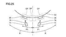
- the cleaning unit can remove liquid medicine from one end at a plurality of cleaning positions, and the cleaning position is at a position that is separated from the supply position to both sides by a distance smaller than the distance between the one ends. Is provided.
- the cleaning position is provided at a position separated from the supply position by a distance that is 1 ⁇ 2 of the distance between the one ends.
- the supply pipe moving unit sets the supply pipe to the cleaning position at predetermined intervals during a dispensing pause time during which dispensing of the liquid medicine from the liquid medicine bottle to the medication bottle is not performed according to the prescription.
- the predetermined time may be set corresponding to the type of liquid medicine accommodated in the liquid medicine bottle.
- a liquid medicine supply device is an apparatus that selectively supplies a liquid medicine to a medication bottle from a plurality of liquid medicine bottles each containing a plurality of different types of liquid medicines. And a plurality of supply pipes through which liquid medicines flow from each of the drug bottles toward the medication bottle, and a supply pipe moving unit that moves the supply pipe relative to the medication bottle.
- the supply tube includes one end through which liquid medication flows out toward the medication bottle.
- the supply pipe moving unit sequentially moves the plurality of supply pipes to a supply position having one end above the upper opening of the prescription bottle and facing the upper opening.
- the liquid medicine supply device further includes a cleaning unit that removes liquid medicine adhering to one end from one end, and a control unit that controls the operation of the liquid medicine supply device.
- the control unit supplies the liquid medicine from the liquid medicine bottle to the prescription bottle according to the prescription and performs the dispensing, and operates the cleaning unit at predetermined intervals during the dispensing pause time when the dispensing is not performed.
- the predetermined time is set corresponding to the type of liquid medicine contained in the liquid medicine bottle.
- control unit preferably operates the cleaning unit when dispensing is completed.
- control unit preferably operates the cleaning unit at the start of dispensing.
- liquid medicine supply device of the present invention dripping of the liquid medicine from the supply pipe can be more reliably suppressed.
- FIG. 3 is a cross-sectional view of the liquid medicine supply device taken along line III-III shown in FIG. 2.
- FIG. 4 is a cross-sectional view of the liquid medicine supply device along line IV-IV shown in FIG. 2.
- FIG. 5 is a cross-sectional view of the liquid medicine supply device taken along line VV shown in FIG. 2.
- It is the schematic which shows the whole structure of a supply pipe
- It is a perspective view which shows the connection part of a tube and a supply nozzle.
- FIG. 10 is a sectional view taken along line XX shown in FIG. 9. It is an internal perspective view which shows the connection part of a tube and a supply nozzle. It is a partial cross-section schematic diagram which shows the supply nozzle which opposes the upper opening of a prescription bottle. It is a schematic diagram which shows the structure of a cleaning part. It is a schematic diagram which shows the condition where a liquid agent is removed from a supply nozzle by the cleaning part. It is a 1st schematic diagram for showing the positional relationship of a supply position and a cleaning position. It is a 2nd schematic diagram for showing the positional relationship of a supply position and a cleaning position.
- FIG. 1 is a perspective view showing a configuration of a liquid medicine supply device 1 according to an embodiment of the present invention.
- FIG. 2 is a front view of the liquid medicine supply apparatus 1 shown in FIG.
- FIG. 3 is a cross-sectional view of the liquid medicine supply apparatus 1 along the line III-III shown in FIG.
- FIG. 4 is a cross-sectional view of the liquid medicine supply device 1 along the line IV-IV shown in FIG.
- FIG. 5 is a cross-sectional view of the liquid medicine supply device 1 along the line VV shown in FIG.
- the liquid medicine supply device 1 according to the present embodiment is used for dispensing the liquid medicine 5 which is a liquid medicine from the liquid medicine bottle 23 containing the liquid medicine 5 to the medication bottle 2 in accordance with a prescription for the patient. It is done.
- the liquid medicine supply device 1 includes a liquid medicine supply unit 3 that supplies the liquid medicine 5 from the liquid medicine bottle 23 to the medication bottle 2, and a weight detection unit 4 that detects the weight of the liquid medicine 5 contained in the medication bottle 2. Prepare. From the weight of the liquid medicine 5 detected by the weight detection unit 4 and the specific gravity of the liquid medicine 5, the volume of the liquid medicine 5 supplied to the prescription bottle 2 is calculated. The liquid medicine supply unit 3 is controlled so that a liquid medicine 5 having a predetermined volume according to the prescription is supplied to the prescription bottle 2.
- the liquid medicine supply unit 3 and the weight detection unit 4 are provided in the housing 6.
- casing 6 is formed in a rectangular parallelepiped shape, and is installed in the horizontal installation surface in the standing state.
- a support frame 8 is provided inside the housing 6.
- the support frame 8 is disposed between the bottom plate 9 of the housing 6 and the top plate 10 of the housing 6, and specifically is disposed near the top plate 10 of the housing 6.
- the internal space of the housing 6 is partitioned by the support frame 8 into an upper space 11 above the support frame 8 and a lower space 12 below the support frame 8.
- a touch panel 14 and printers 17 a and 17 b are disposed on the front surface portion 13 of the housing 6. Further, a lower opening 15 that connects the lower space 12 and the outside of the housing 6 is formed in the front surface portion 13.
- the lower opening 15 is formed between the left and right side portions 16 a and 16 b in the front surface portion 13 of the housing 6.
- a curved plate-like front cover portion 18 that partitions the lower space 12 and the outside of the housing 6 is disposed.
- the front cover portion 18 is formed of a transparent material so that the lower space 12 can be visually recognized from the outside on the front side of the housing 6.
- the front cover portion 18 is attached to one of the left and right side portions 16a and 16b via a hinge, and is provided so as to be rotatable around the axis of the hinge. As a result, the front cover portion 18 can be opened and closed. Yes.
- the liquid medicine supply unit 3 is disposed in the lower space 12 and has a rotating drum 21 that is a rotating body provided to be rotatable about an axis perpendicular to the support frame 8 (hereinafter referred to as “drum axis”), and a support frame. 8, and a drum rotation motor 22 that rotates the rotating drum 21 around the drum axis with respect to the support frame 8.
- the liquid medicine supply unit 3 is also provided on the rotary drum 21 and drives each pump 24 with a plurality of pumps 24 for transferring liquid medicine from a plurality of liquid medicine bottles 23 containing the liquid medicine 5 to the prescription bottle 2. And a pump drive unit 25.
- Each pump 24 may be a tube pump.
- the rotary drum 21 has a pump holding body 31 that holds each pump 24 and a liquid medicine bottle holding body 32 that holds each liquid medicine bottle 23 in an upright state so that the opening portion opens upward.
- the liquid medicine bottle holder 32 is provided below the pump holder 31 and is formed in an annular flat plate shape in plan view.
- Each pump 24 is arranged on the pump holding body 31 at intervals in the circumferential direction of a virtual circle centered on the drum axis (hereinafter referred to as “drum circumferential direction”).
- drum circumferential direction a virtual circle centered on the drum axis
- the number of liquid medicine bottles 23 and pumps 24 mounted on the rotating drum 21 can be arbitrarily changed according to the purpose.
- a plurality of different types of liquid medication 5 may be accommodated in each of the plurality of liquid medication bottles 23.
- the same kind of liquid 5 having a high prescription frequency may be accommodated in a plurality of liquid bottles 23.
- fillers such as a regular water and a simple syrup, may be accommodated in the 1 or several liquid medication bottle 23.
- the pump drive unit 25 selectively drives each of the pumps 24 and selectively supplies the liquid medicine 5 from the plurality of liquid medicine bottles 23 to the medication bottle 2.
- a connecting member 42 is fixed to the tip of the drive shaft 41 that is rotationally driven by the pump drive unit 25.
- a connected member 44 connected to the connecting member 42 is fixed to the rotating shaft 43 of the rotor of each pump 24. By connecting the connecting member 42 and the connected member 44, the rotational force is transmitted to the pump 24.
- the pump 24 is configured to be driven for each pump 24 in conjunction with the rotation of the rotary drum 21.
- the pump drive unit 25 includes a pump drive motor 40 that drives the pump 24 and a movement motor 39 that moves the pump drive motor 40. By driving the moving motor 39, the pump driving motor 40 moves in the front-rear direction. A connected state in which the connecting member 42 of the pump driving motor 40 is connected to the connected member 44 of the pump 24 by the movement of the pump driving motor 40, and a disconnected state in which the connecting member 42 is not connected to the connected member 44. And can be switched. The rotating drum 21 can smoothly rotate with respect to the support frame 8 in the disconnected state.
- the rotating member 21 rotates to a position where the connected member 44 of the specific pump 24 selected based on the prescription information input to the liquid medicine supply device 1 faces the connecting member 42.
- the drum 21 is moved.
- the connecting member 42 is switched to a connected state in which the connecting member 42 is connected to the connected member 44.
- the selected specific pump 24 can be driven, and the liquid medicine 5 supplied from the desired liquid medicine bottle 23 can be dispensed into the prescription bottle 2.
- the connection member 42 and the to-be-connected member 44 are both comprised with the gear, as long as motive power can be transmitted, what kind of structure may be sufficient.
- a plurality of liquid medicine bottles 23 are mounted on the liquid medicine bottle holder 32 of the rotating drum 21.
- a plurality of cups 58 for holding the liquid medicine bottle 23 is attached to the upper side of the liquid medicine bottle holding body 32.
- the cup 58 is formed in a bottomed hollow cylindrical shape.
- the cup 58 functions as a holder that holds the liquid medicine bottle 23.
- the liquid medicine bottle 23 is accommodated in the cup 58, and the bottom of the liquid medicine bottle 23 is held by the cup 58.
- a rotation driving unit 51 that generates a rotational force is disposed below the liquid medicine bottle holder 32.
- the rotation driving unit 51 rotates the liquid medicine bottle 23 along the center line of the liquid medicine bottle 23.
- the liquid medicine 5 accommodated in the liquid medicine bottle 23 passes through the inside of the liquid medicine bottle 23 along the rotation direction of the liquid medicine bottle 23, and the cylinder of the liquid medicine bottle 23. Flow in the circumferential direction of the shaped side.
- the liquid medicine 5 is stirred inside the liquid medicine bottle 23.
- the pump holder 31 of the rotary drum 21 is provided with a pump 24 corresponding to each of the plurality of liquid medicine bottles 23.
- a nozzle mounting plate 53 that is an annular flat plate is provided at the lower end of the pump holder 31.
- the nozzle mounting plate 53 is disposed above the liquid medicine bottle holder 32.
- the nozzle mounting plate 53 and the liquid medicine bottle holder 32 are parallel to each other, and are configured to be rotatable around the drum axis on the horizontal plane together with the rotating drum 21.
- the rotating drum 21 has a function as a supply pipe moving unit that moves a supply pipe 60 described later including the supply nozzle 36.
- the supply nozzle 36 is mounted on the same circumference of the outer periphery of the nozzle mounting plate 53.
- the supply nozzles 36 are arranged on the nozzle mounting plate 53 at equal intervals in the drum circumferential direction on a virtual circle centered on the drum axis.
- An upper opening 2 ⁇ / b> A is formed in the medication bottle 2, and the plurality of supply nozzles 36 are configured such that the supply port 36 ⁇ / b> A can move relative to the upper opening 2 ⁇ / b> A of the medication bottle 2.
- the supply port 36A of the supply nozzle 36 moves relative to the upper opening 2A of the prescription bottle 2
- one of the plurality of supply ports 36A is sequentially arranged opposite to the upper opening 2A.
- the supply nozzle 36 is disposed so as to be inclined at a predetermined angle with respect to the drum axis.
- the liquid medicine 5 flowing out from the supply port 36 ⁇ / b> A of the supply nozzle 36 is supplied into the prescription bottle 2 via the upper opening 2 ⁇ / b> A of the prescription bottle 2. Since the supply nozzle 36 is inclined with respect to the drum axis, the liquid 5 injected into the prescription bottle 2 flows along the inner peripheral side wall of the prescription bottle 2. Thereby, foaming of the liquid medication 5 inside the prescription bottle 2 can be prevented.
- a mounting portion 55 is fixed on the upper side of the nozzle mounting plate 53.
- the supply nozzle 36 is provided so as to be arbitrarily detachable from the attachment portion 55, and is attached to the nozzle attachment plate 53 with the attachment portion 55 interposed therebetween.
- the weight detector 4 is disposed in the lower opening 15.
- the weight detection unit 4 is an electronic balance 45, a casing 46 that houses the electronic balance 45, and is placed and fixed on the electronic balance 45, and the medication bottle 2 stands up so that the upper opening 2A opens upward. And a medication bottle holder 47 to be held.
- the electronic balance 45 detects the weight of the liquid medicine 5 supplied to the medication bottle 2. When the weight of the liquid medicine 5 reaches a predetermined value, the liquid medicine supply unit 3 stops driving the pump 24 and stops supplying the liquid medicine 5 to the prescription bottle 2.
- the electronic balance 45 may be of any type such as a tuning fork type, a load cell type, or an electromagnetic type.
- the casing 46 is provided in a lower portion between the left and right side portions 16 a and 16 b in the front surface portion 13 of the housing 6.
- the medication bottle holder 47 includes a placement table 48 on which the medication bottle 2 is placed, and a holder 49 that is provided on the placement table 48 and holds the medication bottle 2.
- the weight detector 4 is moved up and down by a lifting device 50 as a driving unit shown in FIG.
- the lifting device 50 moves the weight detection unit 4 in the vertical direction so that it can be positioned at two positions, that is, the attachment / detachment position and the dispensing position, and is mounted on the mounting table 48 of the weight detection unit 4 accordingly.
- the prepared medication bottle 2 is moved.
- the attachment / detachment position is a position for attaching the prescription bottle 2 on the mounting table 48 of the liquid medicine supply device 1 or removing the prescription bottle 2 from the mounting table 48.
- the dispensing position is a position where the medication bottle 2 and the supply nozzle 36 are closer to each other than the attachment / detachment position to supply the medication 5 to the medication bottle 2 for dispensing.
- the elevating device 50 causes the medication bottle 2 to reciprocate between the outside and the inside of the casing 6 of the liquid medicine supply device 1 so as to reciprocate between the attachment / detachment position and the dispensing position.
- a blowing nozzle 71 facing the supply port 36A of the supply nozzle 36 is disposed on the front side of the housing 6 in the lower space 12.
- the spray nozzle 71 blows air to the supply port 36A, and removes the liquid medicine 5 attached to the supply port 36A from the supply port 36A.
- the spray nozzle 71 is attached to one of the members constituting the housing 6 via a metal support member.
- the spray nozzle 71 may be attached to the inner surface side of the front cover portion 18. Any known structure can be used as a support structure for disposing the spray nozzle 71 at a predetermined position.
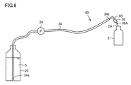
- FIG. 6 is a schematic diagram showing the overall configuration of the supply pipe 60.
- the supply pipe 60 forms a path through which the liquid medicine 5 flows from the liquid medicine bottle 23 toward the medication bottle 2.
- the liquid medicine supply apparatus 1 includes a plurality of supply pipes 60 so that different liquid medicines 5 can be supplied from each of the plurality of liquid medicine bottles 23 to the medication bottle 2.
- the supply pipe 60 includes the supply nozzle 36, the tube 34, and the elbow member 65 described above.
- the tube 34 has a suction end 34a that is one end and a discharge end 34b that is the other end.
- the suction end 34 a opened by the tube 34 is arranged inside the liquid medicine bottle 23 and is immersed in the liquid medicine 5 in the liquid medicine bottle 23.
- the suction end 34 a is an end portion on the side where the liquid medicine 5 is sucked into the tube 34 when the liquid medicine 5 is supplied from the liquid medicine bottle 23 to the prescription bottle 2.
- the discharge end 34 b is an end portion on the side of discharging the liquid medicine 5 from the tube 34 when supplying the liquid medicine 5 from the liquid medicine bottle 23 to the prescription bottle 2.
- the discharge end 34 b of the tube 34 is attached to the elbow member 65.
- the elbow member 65 connects the tube 34 and the supply nozzle 36.
- the supply port 36A in which the end of the supply nozzle 36 is opened forms one end of the supply pipe 60 on the prescription bottle 2 side.
- One end of the supply pipe 60 is arranged to face the upper opening 2 ⁇ / b> A of the prescription bottle 2.
- the supply port 36 ⁇ / b> A of the supply nozzle 36 is arranged to face the upper opening 2 ⁇ / b> A of the prescription bottle 2.
- the liquid medication 5 flows out from the supply pipe 60 toward the prescription bottle 2 via one end of the supply pipe 60.
- the suction end 34a of the tube 34 forms the other end of the supply pipe 60 on the liquid medicine bottle 23 side.
- the other end of the supply pipe 60 is inserted into the liquid medicine bottle 23 and submerged in the liquid medicine 5 accommodated in the liquid medicine bottle 23.
- the pump 24 is used as a power source for sucking the liquid medicine 5 in the liquid medicine bottle 23 toward the supply nozzle 36.
- the pump 24 is a tube pump
- an intermediate portion of the tube 34 between the suction end 34 a and the discharge end 34 b is inserted into the pump 24 and is detachably gripped by the pump 24.
- the liquid medicine 5 in the liquid medicine bottle 23 is sucked into the supply pipe 60 from the suction end 34a, flows through the inside of the supply pipe 60, and passes through the supply port 36A of the supply nozzle 36. It flows out from the supply pipe 60.
- the liquid medicine 5 flowing out from the supply pipe 60 flows into the medication bottle 2 via the upper opening 2 ⁇ / b> A of the medication bottle 2.
- the liquid medicine 5 is transferred from each of the plurality of liquid medicine bottles 23 to the prescription bottle 2 via the supply pipe 60, and the liquid medicine 5 is supplied to the prescription bottle 2.
- different types of liquid medicine 5 or excipients are selectively supplied to the medication bottle 2.
- FIG. 7 is a perspective view showing a connecting portion between the tube 34 and the supply nozzle 36.
- FIG. 8 is a front view showing a connecting portion between the tube 34 and the supply nozzle 36.
- FIG. 9 is a side view showing a connecting portion between the tube 34 and the supply nozzle 36.
- FIG. 10 is a cross-sectional view taken along line XX shown in FIG.
- FIG. 11 is an internal perspective view showing a connecting portion between the tube 34 and the supply nozzle 36. 7 to 11, only a part of the tube 34 in the vicinity of the discharge end 34b is shown, and most of the tube 34 is not shown.
- the elbow member 65 as an example of the bending member has a 90 ° elbow shape as clearly shown in FIGS. 10 and 11.
- the elbow member 65 includes a straight tubular first arm portion 66, a straight tubular second arm portion 67 extending perpendicular to the extending direction of the first arm portion 66, and the first arm portion 66 and the second arm. And a bent portion 68 connecting the portion 67.
- the bent portion 68 has a function as a connecting portion that connects the first arm portion 66 and the second arm portion 67.
- An elbow member 65 having a 90 ° elbow shape is formed by bending the pipe line at the bent portion 68 and providing the first arm portion 66 and the second arm portion 67 at both ends of the bent portion 68.
- the 1st arm part 66, the 2nd arm part 67, and the bending part 68 of the elbow member 65 are the structures which point to each part of the elbow member 65, Comprising: These are not intended that they are separate members. . That is, the elbow member 65 may be formed by bending a straight tubular member, for example, or may be formed as a resin molded product. In such a case, the first arm portion 66 and the second arm portion are formed. 67 and the bent portion 68 are integrally formed.
- the shape of the elbow member 65 is not limited to the 90 ° elbow shape, although it is desirable that the 90 ° elbow shape shown in the figure can be used because a commercially available product can be used and the cost can be reduced.
- Each extending direction of the first arm portion 66 and the second arm portion 67 may form an arbitrary angle such as 45 °, for example.
- the bent portion 68 may not have a bent shape but may have a shape that bends gently.
- the first arm portion 66 and the second arm portion 67 may not have a straight tube shape but may have a bent tube shape. In this case, one of the connecting portions that connects the first arm portion 66 and the second arm portion 67. A part or all may be a straight tube.
- the elbow member 65 may have any shape as long as it can change the flow direction of the liquid medication 5 passing through the elbow member 65.
- the end portion of the first arm portion 66 that engages with the supply nozzle 36 is arranged on the lower side in the vertical direction with respect to the end portion of the first arm portion 66 on the bent portion 68 side, and the second arm portion 67.
- the open end portion of the second arm portion 67 is disposed on the lower side in the vertical direction with respect to the end portion on the bent portion 68 side.
- the second arm portion 67 may be arranged such that the extending direction thereof has an angle larger than 0 ° with respect to the horizontal direction.
- the angle formed by the extending direction of the first arm portion 66 with respect to the horizontal direction is such that when the liquid 5 flowing out from the supply port 36A of the supply nozzle 36 is injected into the prescription bottle 2, the liquid 5 is discharged into the prescription bottle.
- the angle may be set to a large angle so as not to scatter from 2.
- a supply nozzle 36 is attached to the outer peripheral side of the first arm portion 66 of the elbow member 65. By inserting the first arm portion 66 into the supply nozzle 36, the supply nozzle 36 and the elbow member 65 are engaged with each other.
- a tube 34 is attached to the outer peripheral side of the second arm portion 67 of the elbow member 65. By inserting the second arm portion 67 into the tube 34, the tube 34 and the elbow member 65 are engaged with each other.
- the elbow member 65 is held by a holder member 180.
- the holder member 180 is a resin molded product.
- An elbow fixing hole 181 for fixing the elbow member 65 is formed inside the holder member 180.
- the elbow fixing hole 181 is formed when a part of the surface of the holder member 180 is recessed.
- the elbow fixing hole 181 is formed in a shape corresponding to the elbow member 65, that is, a shape capable of accommodating the elbow member 65 inside.
- the elbow member 65 Since the surface of the holder member 180 is recessed to form the elbow fixing hole 181, the elbow member 65 is moved by moving the elbow member 65 in a direction intersecting (typically orthogonal) with the extending direction of the elbow member 65. Can be attached to the elbow fixing hole 181, or the elbow member 65 can be removed from the elbow fixing hole 181. Thus, the elbow member 65 can be easily attached to and detached from the elbow fixing hole 181.
- the holder member 180 is formed with a nozzle insertion hole 183 having a diameter larger than that of the elbow fixing hole 181.
- the elbow fixing hole 181 and the nozzle insertion hole 183 are formed concentrically.
- the tube 34 is attached to the outer peripheral side of the second arm portion 67, and the entire tube 34 is disposed outside the holder member 180.
- the holder member 180 is formed so that the discharge end 34 b of the tube 34 attached to the second arm portion 67 contacts the outer surface of the holder member 180. That is, the elbow fixing hole 181 is formed to have a smaller diameter than the outer diameter of the discharge end 34 b of the tube 34.
- the holder member 180 is provided with a slide portion 182 for fixing the elbow member 65 inside the elbow fixing hole 181.
- a part of the outer surface of the holder member 180 is formed with a groove shape that accommodates the slide portion 182 and allows the slide portion 182 to slide relative to the holder member 180.
- the slide portion 182 is movable in the direction of a double arrow shown in FIG.
- the slide part 182 is made of, for example, a metal material having a rigidity higher than that of the holder member 180.
- the slide part 182 is formed so as to be positioned at a position covering the elbow fixing hole 181 by, for example, a ball-type latch.
- the elbow member 65 accommodated in the elbow fixing hole 181 is covered by the slide part 182.
- the elbow member 65 is positioned with respect to the holder member 180, and in addition, the elbow member 65 is prevented from being naturally removed from the elbow fixing hole 181.
- the elbow member 65 When attaching the elbow member 65 to the holder member 180, first, the elbow member 65 is disposed inside the elbow fixing hole 181. At this time, the tube 34 may or may not be attached to the elbow member 65, but the supply nozzle 36 is not attached to the elbow member 65. After the elbow member 65 is received in the elbow fixing hole 181, the slide portion 182 is slid and the elbow member 65 is positioned by the slide portion 182.
- the supply nozzle 36 is brought close to the elbow member 65 along the extending direction of the first arm portion 66 of the elbow member 65, the first arm portion 66 is inserted into the supply nozzle 36, and the supply nozzle 36 is further moved to the holder member 180. Is inserted into the nozzle insertion hole 183.
- the inner diameter of the nozzle insertion hole 183 is slightly smaller than the outer diameter of the supply nozzle 36.
- the supply nozzle 36 is formed of a material that is flexible and easily elastically deformed, such as rubber or synthetic resin.
- the supply nozzle 36 when the supply nozzle 36 is inserted into the nozzle insertion hole 183, the supply nozzle 36 is elastically deformed so that its outer diameter is slightly reduced, and the supply nozzle 36 comes into close contact with the inner wall of the nozzle insertion hole 183.
- the supply nozzle 36 is firmly attached to the holder member 180, the displacement of the supply nozzle 36 and the removal from the elbow member 65 are suppressed.
- the first arm portion 66 of the elbow member 65 is inserted into the supply nozzle 36, the supply nozzle 36 is reliably positioned with respect to the holder member 180, and at the same time, the elbow member 65 is also attached to the holder member 180. Positioning is performed reliably.
- the holder member 180 is fixed to an interposition member 186 made of a metal material.
- the holder member 180 is formed with a bolt insertion hole 184 that penetrates the holder member 180 in the thickness direction.
- the fixing bolt 189 By inserting the fixing bolt 189 into the bolt insertion hole 184 side and screwing the nut into the fixing bolt 189, the holder member 180 and the interposition member 186 are fixed integrally.
- a plurality of bolt insertion holes 184 are formed in the holder member 180, and the holder member 180 and the interposed member 186 are fixed more securely by fixing the holder member 180 and the interposed member 186 at a plurality of locations, and The positional shift of the holder member 180 with respect to the interposed member 186 can be suppressed.
- the interposition member 186 has a flat plate-shaped leg portion 187. As shown in FIG. 9, the leg portion 187 is provided so as to be separated from the main body portion of the interposition member 186 fixed to the holder member 180.
- the leg portion 187 is formed in a long plate shape extending in one direction and having a longitudinal direction in the direction.
- the interposition member 186 is attached to the attachment portion 55 by engaging the leg portion 187 with the attachment portion 55 fixed to the nozzle attachment plate 53.
- the interposition member 186 is attached to the attachment portion 55 by fitting the leg portion 187 into the reception hole formed in the attachment portion 55, and the interposition member 186 is removed from the attachment portion 55 by removing the leg portion 187 from the reception hole. It is.
- the supply nozzle 36 is attached to the rotary drum 21, and the supply nozzle 36 can rotate integrally with the rotary drum 21.
- the interposition member 186 When the interposition member 186 is attached to the attachment portion 55, the interposition member 186 is disposed so that the longitudinal direction of the leg portion 187 is parallel to the direction of the drum axis.
- the extending direction of the receiving hole formed in the mounting portion 55 is parallel to the direction of the drum axis, and the leg portion 187 is extended along the extending direction of the receiving hole by inserting the leg portion 187 into the receiving hole.
- the interposed member 186 is disposed so that the direction is parallel to the direction of the drum axis.
- the extending direction of the first arm portion 66 and the second arm portion 67 of the elbow member 65 is inclined with respect to the extending direction of the leg portion 187. Since the liquid medicine supply device 1 is usually placed on a flat floor surface, the direction of the drum axis is typically the vertical direction. Therefore, when the leg portion 187 is attached to the attachment portion 55, the extending direction of the first arm portion 66 and the second arm portion 67 of the elbow member 65 becomes a direction inclined with respect to the vertical direction. Therefore, the flow of the liquid medicine 5 which flows from the liquid medicine bottle 23 to the supply nozzle 36 via the tube 34 and the elbow member 65 and moves toward the prescription bottle 2 flows upward in the elbow member 65 and A downward flow toward the bottom is formed.
- the supply pipe 60 has a first portion 61 and a second portion 62.
- the first portion 61 includes the supply port 36A of the supply nozzle 36, and is closest to the prescription bottle 2 in the supply pipe 60 from the supply port 36A to the bent portion 68 via the first arm portion 66 of the elbow member 65.
- the second portion 62 is a part of the supply pipe 60 connected to the first portion 61 that extends from the bent portion 68 to the vicinity of the end including the discharge end 34 b of the tube 34 via the second arm portion 67.
- the leg portion 187 is inserted into the receiving hole of the attachment portion 55, the first arm portion 66 and the second arm portion 66 of the elbow member 65.
- the arm portion 67 is inclined with respect to the vertical direction. Therefore, the liquid medicine 5 transferred from the liquid medicine bottle 23 to the prescription bottle 2 forms a flow that rises when passing through the second portion 62, and forms a flow that goes down when passing through the first portion 61.
- the first portion 61 forms a downward flow of the liquid medicine 5 that reaches the supply port 36 ⁇ / b> A of the supply nozzle 36.
- the second part 62 forms an upward flow of the liquid medicine 5 toward the first part 61.
- the bent portion 68 is disposed at the highest position in the vertical direction, and the bent portion 68 is disposed above the first arm portion 66 and the second arm portion 67.
- the first arm portion 66 of the elbow member 65 is included in the first portion 61.
- the second arm portion 67 of the elbow member 65 is included in the second portion 62. Therefore, the flow of the liquid medicine 5 that flows into the elbow member 65 from the tube 34 and travels toward the bent portion 68 via the second arm portion 67 becomes an upward flow that flows upward with respect to the vertical direction, and from the bent portion 68 to the first arm.
- the flow of the liquid medicine 5 toward the supply port 36A of the supply nozzle 36 via the portion 66 becomes a downward flow that flows downward with respect to the vertical direction.
- the flow direction of the liquid medicine 5 with respect to the horizontal direction is set.
- the path through which the liquid medicine 5 can descend toward the supply port 36 ⁇ / b> A of the supply nozzle 36 that forms one end of the supply pipe 60 is limited to the first portion 61 only.
- the liquid medication 5 flowing out from the supply port 36 ⁇ / b> A by the action of gravity when the pump 24 is stopped is limited to the liquid medication 5 inside the first portion 61.
- the liquid medicine 5 in the supply pipe 60 can be prevented from dripping from the supply port 36A.
- the second portion 62 where the liquid medicine 5 flowing toward the supply port 36 ⁇ / b> A becomes an upward flow is not connected to the first portion 61, and time elapses after the pump 24 is stopped.
- the amount of the liquid medicine 5 that naturally falls toward the supply port 36A was large to some extent. Therefore, it is difficult to avoid dripping of the liquid medicine 5 from the supply port 36A.
- the supply pipe 60 of the present embodiment has a first part 61 that is a part closest to the supply port 36A and a second part 62 that is a part connected to the first part 61.
- the flow direction in the vertical direction of the liquid medicine 5 that flows in the supply pipe 60 toward the supply port 36 ⁇ / b> A varies between the inside of the first portion 61 and the inside of the second portion 62.
- the liquid agent 5 existing inside the supply pipe 60 the liquid agent 5 that can flow toward the supply port 36A by the action of gravity when the pump 24 is stopped adheres to the elbow member 65 or the inner wall of the supply nozzle 36.
- the liquid medicine 5 existing inside the first portion 61 can be limited. By reducing the amount of liquid 5 toward the supply port 36A according to gravity, the dripping of the liquid 5 from the supply port 36A can be more reliably suppressed.
- the dimension of each component of the supply pipe 60 may be determined so that the extension length of the first portion 61 is shorter than the extension length of the second portion 62.
- FIG. 12 is a partial cross-sectional schematic diagram showing the supply nozzle 36 facing the upper opening 2A of the prescription bottle 2. Since the supply nozzle 36 is disposed at a predetermined angle with respect to the drum axis, the supply nozzle 36 is disposed to be inclined with respect to the vertical direction of the prescription bottle 2.
- the liquid medicine 5 flows from the supply port 36 ⁇ / b> A of the supply nozzle 36 toward the inner peripheral side wall of the prescription bottle 2 and is supplied to the prescription bottle 2.
- the liquid medicine 5 remaining inside the supply pipe 60 by adhering to the inner wall of the elbow member 65 and the supply nozzle 36 constituting the supply pipe 60, for example, It flows downward by the action of gravity and adheres to the supply port 36 ⁇ / b> A of the supply nozzle 36.
- the supply port 36 ⁇ / b> A constitutes one end of the supply pipe 60 on the side from which the liquid medicine 5 toward the prescription bottle 2 flows out of the supply pipe 60. If the liquid medication 5 attached to the supply port 36A is left unattended, the liquid medication 5 collected at the supply port 36A may drop and contamination of the liquid medication 5 in the prescription bottle 2 may occur. Alternatively, the liquid medication 5 may adhere to the supply port 36 ⁇ / b> A, and it may be difficult to supply an accurate amount of the liquid medication 5 to the prescription bottle 2. Therefore, the liquid medicine supply device 1 is required to be able to remove the liquid medicine 5 from the supply port 36A.
- the sensor 85 detects that the liquid medicine 5 has adhered to the supply port 36A of the supply nozzle 36.
- the sensor 85 is a non-contact sensor, and includes a transmission unit 86 that transmits a signal such as an electromagnetic wave, light, or an acoustic signal, and a reception unit 87 that receives a signal transmitted from the transmission unit 86.
- the transmitter 86 and the receiver 87 are arranged to face each other with the upper opening 2A of the prescription bottle 2 and the supply port 36A of the supply nozzle 36 interposed therebetween.
- the liquid 5 blocks the signal from the transmitter 86.
- the sensor 85 can detect adhesion of the liquid medicine 5 to the supply port 36A.
- the sensor 85 is a sensor for detecting the position of the medication bottle 2. Since the medication bottle 2 moves up and down between the attachment / detachment position and the dispensing position as described above, when the liquid medication supply apparatus 1 supplies the liquid medication 5 to the medication bottle 2, the medication bottle 2 is in a predetermined dispensing position. A sensor for detecting this is required. Since this sensor also plays a role of detecting the adhesion of the liquid medicine 5 to the supply port 36A, the number of necessary sensors can be reduced, and the cost of the liquid medicine supply apparatus 1 can be reduced.
- FIG. 13 is a schematic diagram illustrating the configuration of the cleaning unit 70.
- the cleaning unit 70 is configured to remove the liquid medication 5 attached to the supply port 36 ⁇ / b> A from the supply port 36 ⁇ / b> A, and sends air to the spray nozzle 71, the blower 73, and the blower 73 to the spray nozzle 71.
- the spray nozzle 71 is formed with a jet port 72, and the air supplied from the blower 73 to the spray nozzle 71 via the vent pipe 74 is jetted from the jet port 72 to form an air jet 76.
- the cleaning unit 70 has a function as an air ejection unit that ejects air from the outside to the supply port 36 ⁇ / b> A of the supply nozzle 36.
- the blower 73 is disposed at an arbitrary location inside the casing 6 of the liquid medicine supply device 1.
- the blower 73 may be disposed at the left and right corners on the back side of the bottom of the lower space 12 in the housing 6.
- the blast port 72 is formed to have an opening area smaller than the cross-sectional area of the vent pipe 74 and the cross-sectional area of the air passage inside the spray nozzle 71.
- FIG. 14 is a schematic diagram showing a situation in which the liquid medicine 5 is removed from the supply nozzle 36 by the cleaning unit 70.
- a plate-shaped receiving member 81 is provided at a position where the supply nozzle 36 is interposed with respect to the spray nozzle 71.
- the receiving member 81 is disposed downstream of the supply port 36 ⁇ / b> A along the flow of the air jet 76.
- a bottomed container-shaped receiving member 82 is attached to the lower end portion of the receiving member 81.
- the receiving member 82 receives the liquid medicine 5 removed from the supply port 36 ⁇ / b> A by the air jet 76 and receives the liquid medicine 5 that hangs downward from the receiving member 81.
- the droplets 78 scattered from the supply port 36A with the receiving members 81 and 82 By receiving the droplets 78 scattered from the supply port 36A with the receiving members 81 and 82, the droplets 78 blown off from the supply port 36A by the air jet 76 are attached to the other components of the liquid medicine supply device 1. It can be avoided reliably.
- a bottomed container-shaped receiving member 83 is provided below the spray nozzle 71.
- the receiving member 83 also receives the liquid medicine 5 removed from the supply port 36 ⁇ / b> A by the air jet 76.
- the cleaning position is set at a position different from the supply position where the supply nozzle 36 should be disposed in order to supply the liquid medicine 5 from the supply nozzle 36 to the prescription bottle 2.
- the spray nozzle 71 sprays an air jet 76 to the supply nozzle 36 disposed at the cleaning position. Therefore, the spray nozzle 71 and the receiving members 81, 82, 83 do not hinder the supply of the liquid medicine 5 to the prescription bottle 2.
- the spray nozzle 71 and the receiving members 81, 82, and 83 shown in FIG. 14 are supported by the casing 6 of the liquid medicine supply device 1 and do not rotate with the rotation of the rotary drum 21. Therefore, the supply pipe 60 including the supply nozzle 36 is provided so as to be movable relative to the spray nozzle 71 and the receiving members 81, 82, and 83.
- the cleaning unit 70 for removing the liquid medication 5 from the supply port 36A of the supply nozzle 36 is not limited to the above-described configuration that ejects air.
- the cleaning unit 70 may have an arbitrary configuration as long as it has a function of removing the liquid medicine 5 attached to the supply nozzle 36.
- the cleaning unit 70 may have a cleaning member such as a brush that wipes the supply port 36A and removes the liquid medicine 5 from the supply port 36A, and has a configuration that can clean and dry the supply port 36A. Also good.
- the cleaning unit 70 may have an absorption member that is in contact with the supply port 36A to soak and absorb the liquid agent 5, or a configuration that sucks and removes the liquid agent 5 from the supply port 36A.
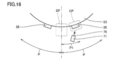
- 15 and 16 are schematic diagrams for illustrating the positional relationship between the supply position SP and the cleaning position CP.
- a part of the nozzle mounting plate 53 shown in FIG. 5 is schematically shown in an arc shape centered on the drum axis, and one of the plurality of supply nozzles 36 mounted on the nozzle mounting plate 53 is shown.
- a partial supply nozzle 36 is shown schematically.
- the plurality of supply nozzles 36 are arranged at equal intervals in the circumferential direction of the arc centered on the drum axis.
- the distance along the drum circumferential direction between the supply ports 36A of the two adjacent supply nozzles 36 is shown as a distance P in FIGS.
- the dotted line frame with the reference symbol SP indicates the supply position SP where the liquid medicine 5 is supplied to the lower prescription bottle 2 via the supply nozzle 36.
- the supply nozzle 36 When the supply nozzle 36 is in the supply position SP, the supply port 36A is disposed above the upper opening 2A of the prescription bottle 2, and the supply port 36A faces the upper opening 2A.
- a dotted line frame denoted by reference sign AP indicates an adjacent position AP where a supply nozzle 36 adjacent to the supply nozzle 36 is disposed when a certain supply nozzle 36 is disposed at the supply position SP.
- a dotted line frame with a symbol CP indicates a cleaning position CP where the liquid 5 adhering to the supply port 36A is removed from the supply port 36A of the supply nozzle 36.
- the supply nozzle 36 is at the cleaning position CP, the supply port 36 ⁇ / b> A is opposed to the blowout port 72 of the spray nozzle 71 of the cleaning unit 70.
- the supply nozzle 36 is disposed at the cleaning position CP, the liquid 5 attached to the supply port 36A is blown off by the air jet 76 ejected from the spray port 72, and the liquid 5 is removed from the supply port 36A.
- the distance between the supply ports 36A of the two adjacent supply nozzles 36 is the interval P
- the distance between the supply position SP and the adjacent position AP along the arc centered on the drum axis is as shown in FIG. The interval P.
- the distance between the supply position SP and the cleaning position CP along the circular arc centered on the drum axis is shown as a distance P1 smaller than the interval P in FIG.
- the spray nozzle 71 is arrange
- the cleaning position CP is provided at a position away from the supply position SP by a distance P1.
- the distance P1 is set as a distance that is half the interval P.
- the cleaning position CP is provided at a position that is separated from the supply position SP by a distance 1 ⁇ 2 of the interval P.
- the relationship P1 P / 2 is established between the interval P and the distance P1.
- the supply nozzle 36 is attached to the nozzle attachment plate 53, and rotates around the drum axis as the rotary drum 21 rotates.
- the supply nozzle 36 moves along the drum circumferential direction, which is the circumferential direction of a virtual circle centered on the drum axis.
- the supply pipe 60 including the supply nozzle 36 moves in the drum circumferential direction by the rotation of the rotary drum 21 and moves relative to the prescription bottle 2.
- the supply nozzle 36 passes through the adjacent position AP, the cleaning position CP, the supply position SP, and the adjacent position AP in this order. At this time, the supply nozzle 36 moves to the supply position SP after passing through the cleaning position CP.
- the plurality of supply ports 36A sequentially move to the supply position SP via the cleaning position CP.
- the supply nozzle 36 moves to the supply position SP after the liquid medication 5 is removed from the supply port 36A at the cleaning position CP, and the liquid medication 5 is supplied to the prescription bottle 2 from the supply nozzle 36 after cleaning.
- the supply nozzle 36 passes above the upper opening 2A facing the upper opening 2A of the prescription bottle 2 after being cleaned at the cleaning position CP. In this way, dripping from the supply nozzle 36 passing above the upper opening 2A can be suppressed. Therefore, it is possible to suppress the occurrence of contamination in which the liquid medication 5 of a type that is not scheduled to be supplied to the medication bottle 2 is mixed into the medication bottle 2.
- the supply nozzle 36 passes through the adjacent position AP, the supply position SP, the cleaning position CP, and the adjacent position AP in this order. At this time, the supply nozzle 36 moves to the cleaning position CP after passing through the supply position SP.
- the plurality of supply ports 36A sequentially move from the supply position SP to the cleaning position CP.
- the supply nozzle 36 that has supplied the liquid medication 5 to the medication bottle 2 at the supply position SP immediately moves to the cleaning position CP.
- the cleaning position CP is provided between the supply position SP and the adjacent position AP.
- the cleaning position CP is provided at a position up to the separation position P from the supply position SP along the drum circumferential direction.
- the supply port 36A to be cleaned is in a position that does not face the upper opening 2A of the prescription bottle 2, so that the liquid medicine 5 that is removed from the supply port 36A at the time of cleaning is the prescription bottle 2 It can suppress mixing in.
- cleaning the supply port 36A at the cleaning position CP the other supply nozzle 36 adjacent to the supply nozzle 36 to be cleaned is in a position not facing the upper opening 2A of the prescription bottle 2, so that the other supply nozzle 36 is cleaned during cleaning. It is possible to prevent the liquid 5 from dripping from being mixed into the medication bottle 2.
- the cleaning position CP is set at the center between the supply position SP and the adjacent position AP.
- the distance P1 between the supply position SP and the cleaning position CP is set to one half of the interval P between the supply ports 36A of the two adjacent supply nozzles 36.
- the supply nozzle 36 during cleaning is arranged at a position farthest in the drum circumferential direction with respect to both the supply position SP and the adjacent position AP.
- the cleaning unit 70 is arranged such that the flow direction of the air jet 76 blown from the blowing nozzle 71 is away from the alternate long and short dash line shown in FIG.
- the air blown out from the spray nozzle 71 flows in a direction away from the supply position SP, which is different from the direction toward the supply position SP.
- the spray nozzle 71 is disposed on the front side inside the housing 6 of the liquid medicine supply device 1.
- the flow direction of the air jet 76 blown from the spray nozzle 71 is a direction from the front side of the liquid medicine supply device 1 toward the rear side.
- the air blown from the spray nozzle 71 flows in the direction from the outside to the inside of the liquid medicine supply device 1 and is blown to the supply nozzle 36.
- FIG. 17 is a block diagram showing a configuration of the liquid medicine supply device 1.
- the liquid medicine supply apparatus 1 includes a control unit 90 that controls the operation of the whole liquid medicine supply apparatus 1.
- the touch panel 14 functions as an input unit for inputting various parameters related to the operation of the liquid medicine supply device 1 such as prescription data, and various information such as a patient name and a pharmacist name.
- the touch panel 14 also functions as a display unit that displays the operation state of the liquid medicine supply device 1.
- the liquid supply device 1 may include, for example, a lamp that is turned on when a malfunction of the liquid supply device 1 occurs as a display unit.
- the electronic balance 45 detects the weight of the liquid medicine 5 supplied to the prescription bottle 2 and inputs the detected weight value to the control unit 90.
- the control unit 90 supplies a predetermined amount of the liquid medicine 5 to the prescription bottle 2 while receiving the weight data of the liquid medicine 5 in the prescription bottle 2 from the electronic balance 45.
- the sensor 85 detects that the prescription bottle 2 is at the dispensing position and the adhesion of the liquid medicine 5 to the supply port 36 ⁇ / b> A, and inputs the detection result to the control unit 90.
- the liquid medicine supply device 1 includes bottle position detection means 91 that detects the position of each liquid medicine bottle 23 in the lower space 12 inside the housing 6.
- the bottle position detection means 91 may be, for example, various sensors, and the sensor may detect a rotation angle of the liquid medicine bottle holder 32 around the drum axis. As the rotary drum 21 rotates, the liquid medicine bottle 23 rotates around the drum axis, so that the current position of the liquid medicine bottle 23 changes frequently. The current position of the liquid medicine bottle 23 is accurately detected using the bottle position detecting means 91, and data relating to the detected current position of the liquid medicine bottle 23 is input to the control unit 90.
- the liquid medicine supply device 1 also includes a communication unit 92 for communicating with an external device and receiving data from the external device.
- Various parameters related to the operation of the liquid medicine supply device 1 may be input to the control unit 90 by the operation of the touch panel 14 described above, or alternatively, the control unit 90 from an external computer via the communication unit 92. May be entered.
- the liquid medicine supply device 1 also includes a memory 93 for the controller 90 to perform calculations.
- the data of the liquid medicine 5 stored in the liquid medicine bottle 23 mounted on the liquid medicine supply device 1, the data relating to the current position of the liquid medicine bottle 23, and the time when the previous nozzle cleaning was performed are stored. Data is stored.
- the liquid medicine supply device 1 also includes a recording medium access unit 94 for mounting a removable recording medium. The data of the liquid medicine 5 described above may be stored in various recording media attached to the recording medium access unit 94 and appropriately read from the recording medium by the control unit 90.
- the control unit 90 controls the liquid medicine supply device 1 based on the information input from the various devices described above. Specifically, a control signal is transmitted from the control unit 90 to the drum rotating motor 22, the moving motor 39, the pump driving motor 40, the stirring motor 52 for stirring the liquid medication 5, and the lifting device 50.
- the liquid medicine 5 is supplied from the liquid medicine bottle 23 to the prescription bottle 2 by appropriately operating and stopping each motor. After the supply of the liquid medication 5 is completed, a piece of paper on which the dispensing result is printed is output from the printers 17a and 17b constituting the output unit 17.
- a control signal is transmitted from the control unit 90 to the blower 73 and the blower 5 is appropriately operated, whereby the liquid medicine 5 is removed from the supply port 36 ⁇ / b> A of the supply nozzle 36.
- FIG. 18 is an example of a table showing settings for performing nozzle cleaning.
- the liquid medicine supply device 1 of the present embodiment can arbitrarily set whether or not to clean the supply nozzle 36 when the device is started, when dispensing is started according to the prescription, and when dispensing is completed.
- the supply nozzle 36 can be set to be cleaned at all occasions when the apparatus is started, when dispensing starts, and when dispensing is completed.
- An operator such as a pharmacist who operates the liquid medicine supply device 1 can arbitrarily change the setting of the nozzle cleaning in consideration of the time required for cleaning the supply nozzle 36, the frequency of dispensing, and the like.
- the operator may be able to input nozzle cleaning setting to the control unit 90 by operating the touch panel 14.
- FIG. 19 is an example of a table showing the setting of time related to nozzle cleaning.
- the liquid medicine supply device 1 of the present embodiment is capable of nozzle cleaning every predetermined time during the dispensing pause time when dispensing according to the prescription is not performed.
- the “nozzle cleaning inquiry interval” shown in FIG. 19 is used to determine whether or not to perform nozzle cleaning after a predetermined time has elapsed since the previous nozzle cleaning during nozzle cleaning during the dispensing pause time. Is a set time T1 until an inquiry is made as to whether or not to perform nozzle cleaning when nozzle cleaning is not performed.
- the “nozzle cleaning inquiry interval” is set to 10 minutes, for example.
- the “nozzle cleaning interval” is a set time T2 selected from a plurality of selectable values such as 30 minutes, 60 minutes, and 90 minutes.
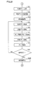
- FIG. 20 is a flowchart when the liquid medicine supply device 1 is started up.
- the control unit 90 causes the liquid medicine such as each motor to be used.
- the devices included in the supply device 1 are checked at the time of startup, and it is confirmed that all devices can operate normally.
- step (S13) it is determined whether or not to perform nozzle cleaning at startup.
- the control unit 90 refers to the table shown in FIG. 18 and recognizes whether or not it is set to perform nozzle cleaning at the time of activation.
- step (S14) If it is determined in step (S13) that the nozzle cleaning is performed at the time of activation, nozzle cleaning is performed in step (S14). Specifically, a control signal is transmitted from the control unit 90 to the blower 73 and the drum rotation motor 22, the blower 73 for supplying air to the spray nozzle 71 is activated, and the rotary drum 21 rotates. At this time, the rotating drum 21 rotates and the air jet 76 is sprayed from the spray nozzle 71 to all of the plurality of supply nozzles 36 included in the liquid medicine supply device 1. As a result, the liquid medicine 5 attached to the supply ports 36A is removed from the supply ports 36A of all the supply nozzles 36.
- step (S15) the control unit 90 records the time when the cleaning unit 70 is operated and the nozzle cleaning is performed in the memory 93. As will be described in detail later, this time is used as a starting point for the time when nozzle cleaning is not performed. Thereafter, in step (S16), the control unit 90 further instructs the drum rotating motor 22 to move the rotating drum 21 to the initial position. In this initial position, for example, in a state where the rotary drum 21 has moved to the initial position, no supply nozzle 36 is disposed at the supply position SP, and there is a supply position SP between two adjacent supply nozzles 36. As set. Alternatively, a position where any one of the supply nozzles 36 is disposed at the supply position SP may be set as the initial position.
- step (S17) When the movement to the initial position is completed, the process proceeds to step (S17), and the liquid supply device 1 enters a standby state. If it is determined in step (S13) that the control unit 90 referring to the table shown in FIG. 18 is set so as not to perform nozzle cleaning at the time of startup, the process proceeds to step (S17) as it is and liquid supply is performed. The device 1 enters a standby state. In this way, a series of operations at the time of starting the liquid medicine supply device 1 is performed.
- FIGS. 21 to 23 are flowcharts showing the liquid medicine supply process to the prescription bottle 2.
- the start of dispensing is first instructed in step (S21)
- a command for starting the supply of the liquid medicine 5 to the bottle 2 is issued.
- the operator may operate the touch panel 14 to select the prescription and touch the start button to start dispensing.
- the control unit 90 receives a prescription via the communication unit 92, dispensing may be started immediately.
- the control unit 90 instructs the printers 17a and 17b to print a label for sticking the medication bottle 2 on which a patient name, a pharmacy name, a medication time, a medication amount, and the like are printed.
- step (S22) it is determined whether or not to perform nozzle cleaning at the start of dispensing.
- the control unit 90 refers to the table shown in FIG. 18 and recognizes whether or not the setting is to perform nozzle cleaning at the start of dispensing.
- step (S23) If it is determined in step (S22) that the setting is to perform nozzle cleaning at the start of dispensing, then in step (S23), whether or not a predetermined time has elapsed since the previous nozzle cleaning. Is judged.
- the control unit 90 calculates the time from the previous nozzle cleaning to the current time based on the previous nozzle cleaning time recorded in the memory 93 and the current time.
- the control unit 90 further compares the calculated time with a predetermined time set as a nozzle cleaning interval that is a threshold value, and the predetermined time has already elapsed or has elapsed since the previous nozzle cleaning. Judge whether or not.
- the nozzle cleaning After the nozzle cleaning is completed, it takes a certain amount of time for the amount of liquid medicine 5 that can be dripped from the supply port 36A of the supply nozzle 36 to accumulate in the supply port 36A. If dispensing has been started without delay after the previous nozzle cleaning is completed, the amount of liquid 5 that accumulates in the supply port 36A of the supply nozzle 36 is sufficiently small to prevent liquid dripping from the supply port 36A. it is conceivable that.
- step (S23) If it is determined in step (S23) that a predetermined time has already passed since the previous nozzle cleaning, nozzle cleaning is performed in step (S24), and the supply ports of all supply nozzles 36 are supplied.
- the liquid medicine 5 attached to the supply port 36A is removed from 36A.
- the cleaning unit 70 By operating the cleaning unit 70 at the start of dispensing, it is possible to remove the liquid medication 5 that has been left standing at the supply port 36A for a long time from the supply port 36A, so that the liquid medicine can be stably supplied to the prescription bottle 2. And the accuracy of dispensing can be improved. Moreover, dripping into the prescription bottle 2 from the supply nozzle 36 that passes above the upper opening 2A of the prescription bottle 2 can be prevented.
- step (S25) When the cleaning of all the supply nozzles 36 is completed, the time at which the nozzle cleaning is performed is recorded in the memory 93 in step (S25). Thereafter, in step (S26), the rotary drum 21 moves to the initial position. Subsequently, in step (S27), it is determined whether or not the medication bottle 2 has been set. If it is determined in step (S22) that no nozzle cleaning is performed, or if it is determined in step (S23) that a predetermined time has not elapsed, the determination in step (S27) is immediately performed. .
- step (S27) it is determined whether or not the medication bottle 2 is being held by the medication bottle holder 47 described with reference to FIGS.
- the touch panel 14 is displayed to urge the operator to set the medication bottle 2.
- the operator sets the medication bottle 2 on the mounting table 48 in the attachment / detachment position for installing the medication bottle 2 on the mounting table 48 and holds the medication bottle 2 on the medication bottle holder 47
- the medication on the touch panel 14 is displayed.
- the button for instructing the completion of setting the bottle 2 is operated.
- the set completion button of the medication bottle 2 is operated, it is determined that the medication bottle is held by the medication bottle holder 47, and the process proceeds to the step (S31) via the connector A.
- the prescription bottle 2 is set on the mounting table 48 in advance. Rather than starting dispensing, it is more preferable to set the medication bottle 2 after completion of nozzle cleaning in step (S24).
- step (S31) the control unit 90 transmits a control signal to the elevating device 50, and the elevating device 50 moves the weight detecting unit 4 upward, so that the medication bottle 2 rises from the attachment / detachment position to the dispensing position.
- the weight detection unit 4 moves upward until it reaches a dispensing position where the liquid medicine 5 can be supplied from the supply nozzle 36 to the prescription bottle 2.
- the vertical position of the prescription bottle 2 is confirmed in step (S32).
- the upper opening 2A of the medication bottle 2 reaches a predetermined position, the position of the medication bottle 2 is detected by the sensor 85 shown in FIG.
- the control unit 90 receives a signal indicating the position of the medication bottle 2 from the sensor 85 and confirms the position of the medication bottle 2.
- step (S33) the prescription bottle 2 is moved to a position where the rotation of the rotary drum 21 is not hindered. Specifically, a control signal is sent from the control unit 90 to the lifting device 50, and the lifting device 50 moves downward to some extent, so that the medication bottle 2 also moves downward.
- the moving direction of the prescription bottle 2 is not limited to the vertical direction, and may be a direction away from the rotating drum 21, for example.
- the drum rotating motor 22 is controlled and the rotating drum 21 is rotated in the next step (S34).
- the control unit 90 transmits a control signal to the drum rotating motor 22 and transmits the driving force of the drum rotating motor 22 to the rotating drum 21.
- the liquid medicine bottle 23 is placed on the liquid medicine bottle holder 32 attached to the rotating drum 21 and the drum rotating motor 22 is driven, whereby the rotating drum 21 rotates and the liquid medicine bottle 23 is moved in the horizontal direction. Move to.
- the liquid medicine bottle 23 containing the liquid medicine 5 or excipient to be supplied next to the prescription bottle 2 and the supply port 36 ⁇ / b> A of the supply nozzle 36 are included in the liquid medicine supply device 1. It is arranged on the forefront side. Until the supply pipe 60 corresponding to the liquid medicine 5 to be supplied to the prescription bottle 2 reaches the position where the supply port 36A of the supply nozzle 36 faces the upper opening 2A of the prescription bottle 2 by the rotation of the rotary drum 21, It moves horizontally along the drum circumferential direction.
- the liquid medicine bottle 23 By arranging the liquid medicine bottle 23 on the front side of the apparatus, the operator who dispenses the liquid medicine 5 visually confirms the type of the liquid medicine 5 to be dispensed from the front of the liquid medicine supply apparatus 1. Can do.
- step (S35) the liquid medicine 5 adheres to the supply port 36A at the tip of the supply nozzle 36 at the supply position SP facing the upper opening 2A of the prescription bottle 2 in the next step (S35). Determine whether or not. Using the sensor 85 described above, the adhesion of the liquid medicine 5 to the supply port 36A is detected. If it is determined in step (S35) that the sensor 85 detects adhesion of the liquid medicine 5 to the supply nozzle 36 and it is determined that the liquid medicine 5 is attached to the supply port 36A, then in step (S36). Nozzle cleaning is performed.
- the blower 73 for supplying air to the spray nozzle 71 is activated, and the rotary drum 21 rotates. Then, the supply nozzle 36 moves to the cleaning position CP.
- an air jet 76 is sprayed from the spray nozzle 71 to one supply nozzle 36 for which it is determined that the liquid medication 5 is attached to the supply port 36A. Due to the rotation of the rotary drum 21, one supply nozzle 36 that is determined to have the liquid 5 attached to the supply port 36 ⁇ / b> A moves to the cleaning position CP. Thereby, the liquid medicine 5 attached to the supply port 36A is removed from the supply port 36A of the one supply nozzle 36. After removing the liquid medication 5 from the supply port 36A for a predetermined time, the blower 73 is stopped. Thereafter, the rotary drum 21 rotates in the reverse direction, and the cleaned supply nozzle 36 moves again to the supply position SP.
- step (S35) If it is determined in step (S35) that the liquid 5 is not attached to the supply port 36A, the nozzle cleaning in step (S36) is not performed, and the process proceeds to step (S37). Steps (S35) and (S36) may be omitted as appropriate. If it is determined in step (S35) that the liquid 5 is attached to the supply port 36A, the operator manually enters the supply port 36A where the liquid 5 is attached to the touch panel 14. An indication to prompt cleaning may be displayed.
- step (S37) the pump driving motor 40 is moved forward, and the connecting member 42 of the pump driving motor 40 is connected to the connected member 44 of the pump 24.
- the rotation of the pump driving motor 40 can be transmitted to the pump 24, that is, the pump 24 can be driven.
- step (S38) the medication bottle 2 moved in step (S33) is moved again to the dispensing position.
- the control signal is sent from the control unit 90 to the lifting device 50 and the lifting device 50 moves upward again, the medication bottle 2 also moves upward.
- the prescription bottle 2 is arrange
- step (S39) the control unit 90 transmits a control signal to the pump driving motor 40, and the pump driving unit 25 selectively drives the pump 24 corresponding to the selected liquid medicine bottle 23.
- the pump 24 By driving the pump 24, a predetermined amount of the liquid medicine 5 in the liquid medicine bottle 23 determined by the prescription is supplied from the liquid medicine bottle 23 via the supply pipe 60 to the prescription bottle 2.
- the control unit 90 receives the weight data of the liquid medicine 5 in the prescription bottle 2 from the electronic balance 45 and confirms the amount of the liquid medicine 5 supplied to the prescription bottle 2.
- a predetermined amount of liquid 5 is supplied to the medication bottle 2, the dispensing of the first liquid 5 into the medication bottle 2 is completed.
- the liquid 24 flows backward from the first portion 61 of the supply pipe 60 to the second portion 62 by rotating the pump 24 in the reverse direction, and remains in the first portion 61.
- the liquid medicine 5 is moved to the second portion 62.
- the quantity of the liquid medicine 5 which exists in the 1st part 61 can be reduced, and it can further suppress that the liquid medicine 5 in the 1st part 61 moves to the supply port 36A by gravity.
- the supply port 36A of the supply nozzle 36 is sealed and the internal space of the supply nozzle 36 can be depressurized, the remaining amount of the liquid medicine 5 in the first portion 61 can be more efficiently reduced.
- step (S40) it is determined whether or not the supply of the liquid medication 5 (and the excipient if necessary) to the medication bottle 2 according to the prescription is completed and the dispensing is completed. .
- the process returns to the step (S33), and the liquid medicine bottle 23 in which the liquid medicine 5 to be supplied next is accommodated and the supply port 36A of the supply nozzle 36 are the front side of the apparatus.
- the rotary drum 21 is rotated so that the next liquid medicine 5 or excipient is supplied to the dosing bottle 2.
- step (S41) via the connector B, and the lifting device 50 moves the mounting table 48 downward, whereby the medication bottle 2 goes down.
- a control signal is transmitted from the control unit 90 to the lifting device 50, and the lifting device 50 moves the mounting table 48 downward, so that the medication bottle 2 is lowered.
- the mounting table 48 moves downward until it returns from the dispensing position to the attachment / detachment position.
- step (S42) it is determined whether or not to perform nozzle cleaning when dispensing is completed.
- the control unit 90 refers to the table shown in FIG. 18 and recognizes whether or not the setting is such that nozzle cleaning is performed when dispensing is completed.
- step (S42) If it is determined in step (S42) that the nozzle cleaning is performed when dispensing is completed, nozzle cleaning is performed in step (S43), and the supply ports 36A of all the supply nozzles 36 are used. The liquid medicine 5 attached to the supply port 36A is removed.
- the cleaning unit 70 is operated to remove the liquid 5 from the supply port 36A, so that dripping from the supply nozzle 36 through which the liquid 5 has flowed along with the dispensing can be suppressed, and the liquid supply The occurrence of dripping into the device 1 can be suppressed.
- step (S45) the rotary drum 21 moves to the initial position. If it is determined in step (S42) that the nozzle cleaning is not performed when dispensing is completed, the rotary drum 21 is immediately moved in step (S45). Thereafter, the process proceeds to step (S46), and the liquid medicine supply device 1 enters a standby state. In this way, the dispensing using the liquid medicine supply device 1 of the present embodiment is completed.
- FIG. 24 is a flowchart of nozzle cleaning during the dispensing pause time.
- FIG. 24 shows a predetermined period of time in order to prevent liquid dripping by removing the liquid agent 5 accumulated in the supply port 36A from the supply port 36A with the passage of time during the dispensing pause time when dispensing according to the prescription is not performed.
- a flow when the cleaning unit 70 is operated and nozzle cleaning is performed every time is illustrated.
- step (S51) as in step (S23) described above, it is determined whether or not a predetermined time has elapsed since the previous nozzle cleaning.
- the predetermined time may be set in accordance with the type of liquid 5 contained in a plurality of liquid bottles 23.
- the liquid medicine 5 varies in time until it drips from the supply nozzle 36 depending on the type. For example, the liquid 5 having a low viscosity or the liquid 5 having a high specific gravity drips in a shorter time. Therefore, it is possible to set a predetermined time corresponding to a plurality of types of liquid medication 5 accommodated in the liquid medication bottle 23.
- the time required for the liquid medicine 5 with the shortest time for dripping to occur may be set in accordance with the liquid medicine 5 with the shortest time for dripping occurrence.
- the predetermined time is changed corresponding to the change. May be.
- step (S52) the liquid supply device 1 is in a state where nozzle cleaning can be permitted. It is determined whether or not. Depending on the current state of the liquid medicine supply device 1, there may be a case where nozzle cleaning with rotation of the rotary drum 21 cannot be performed. As a case where nozzle cleaning cannot be performed, for example, when an operator who operates the liquid supply device 1 is under maintenance of the liquid supply device 1 such as cleaning the inside of the housing 6, or replacement of the liquid solution bottle 23 In the case of being inside, the case where the front cover part 18 is in the open state is exemplified.
- step (S52) If the liquid supply device 1 is in a setting state in which nozzle cleaning cannot be permitted, the determination in step (S52) is repeated.
- step (S52) If it is determined in step (S52) that the liquid medicine supply device 1 is in a state where nozzle cleaning can be permitted, then in step (S54), it is determined whether or not dispensing is in progress. Since nozzle cleaning cannot be performed during dispensing, it is necessary not to be dispensed in order to perform nozzle cleaning. If it is determined in step (S54) that dispensing is not in progress, then in step (S55), it is determined whether or not to perform nozzle cleaning.
- step (S55) an operator operating the liquid medicine supply device 1 selects whether or not to perform nozzle cleaning.
- the screen for allowing the operator to select whether or not to perform nozzle cleaning may be displayed on the touch panel 14, and the operator may select whether or not to perform nozzle cleaning by touching a predetermined area on the screen.
- nozzle cleaning is then performed in step (S56). At this time, nozzle cleaning may be performed on all the supply nozzles 36.
- the supply nozzle 36 is sequentially moved to the supply position SP, the adhesion of the liquid medicine 5 to the supply port 36A is detected using the sensor 85 at the supply position SP, and the liquid medicine 5 is attached to the supply port 36A.
- Nozzle cleaning may be performed only for the nozzle 36.
- another sensor different from the sensor 85 is arranged at the cleaning position CP, the supply nozzle 36 is sequentially moved to the cleaning position CP, and the liquid medicine 5 to the supply port 36A is used by using the other sensor at the cleaning position CP. Nozzle cleaning may be performed only for the supply nozzle 36 where the liquid 5 is attached to the supply port 36A.
- step (S57) the time at which the nozzle cleaning is performed is recorded in the memory 93 in step (S57). Thereafter, in step (S58), the rotary drum 21 moves to the initial position, and then proceeds to step (S59), where the liquid supply device 1 enters a standby state.
- step (S55) If it is determined in step (S55) that nozzle cleaning is not performed, the control unit 90 recognizes the nozzle cleaning inquiry interval with reference to the table shown in FIG. Thereafter, the process proceeds to step (S60), and after the time set as the nozzle cleaning inquiry interval has elapsed, the control flow is returned.
- step (S51) When it is determined in step (S51) that the predetermined time has not elapsed since the previous nozzle cleaning, and also when it is determined that dispensing is in progress in step (S54), the control flow is as follows. Returned. When the control flow shown in FIG. 24 is returned, the process returns to step (S51) again, and the flow for performing nozzle cleaning every predetermined time during the dispensing pause time is continued.
- the time at which nozzle cleaning is performed is the starting point for the elapse of a predetermined time since the previous nozzle cleaning.
- steps (S15), (S25), (S44), and (S57) described above the time when the nozzle cleaning is performed is recorded in the memory 93 each time.
- the nozzle cleaning can be performed if the predetermined time has elapsed, but the nozzle cleaning may not be performed if the predetermined time has not elapsed.
- the control unit 90 calculates the time from the previous nozzle cleaning to the current time based on the previous nozzle cleaning time stored in the memory 93 and the current time. calculate.
- the control unit 90 further compares the calculated time with a predetermined time set as a nozzle cleaning interval that is a threshold value, and the predetermined time has already elapsed or has elapsed since the previous nozzle cleaning. Judge whether or not. Therefore, it is possible to more reliably suppress the occurrence of the problem that the nozzle 5 is not cleaned for a long time and the liquid medicine 5 drops from the supply port 36A.
- the setting of the time that is the end point of the predetermined time indicating that the predetermined time has elapsed since the previous nozzle cleaning is updated every time the nozzle cleaning is performed, and the setting of the time when the cleaning unit 70 is to be operated next and the nozzle cleaning should be performed. May be updated.
- the control unit 90 registers the predetermined time set as the threshold nozzle cleaning interval as a timer, and the predetermined time registered by the timer has elapsed from the previous nozzle cleaning time. Alternatively, it may be determined whether it has not yet elapsed.
- the supply pipe 60 is configured by the tube 34, the elbow member 65, and the supply nozzle 36, but is not limited to this example.
- the tube 34 and the supply nozzle 36 may be connected by a bend joint having a curved shape.
- the flow of the liquid 5 toward the one end is raised and then lowered to supply the liquid 5 from one end to the prescription bottle 2.
- the elbow member 65 is not essential. That is, it is also possible to define the flow direction of the liquid medication 5 by arranging the tube 34 to be curved or bent. Further, the supply nozzle 36 may be omitted, and the supply pipe 60 may be formed by the single tube 34.
- the nozzles 36 may be sequentially arranged at the supply position SP. If the supply ports 36 ⁇ / b> A of the plurality of supply nozzles 36 can be sequentially moved to a position facing the upper opening 2 ⁇ / b> A above the upper opening 2 ⁇ / b> A of the prescription bottle 2, how the supply pipe 60 is relative to the prescription bottle 2. You may move.
- the operation of the blower 73 may be continued while dispensing is performed, and the nozzle mounting plate 53 may be rotated clockwise and counterclockwise. .
- the nozzle mounting plate 53 is provided. Switch the direction of rotation. Thereafter, the supply nozzle 36 moves counterclockwise to the cleaning position CP, and after the liquid medication 5 is removed from the supply port 36A at the cleaning position CP, the rotation direction of the nozzle mounting plate 53 is switched again.
- the supply nozzle 36 corresponding to the liquid medicine 5 to be supplied also moves in the same manner as the supply nozzle 36.
- the dripping from the supply nozzle 36 which passes above the upper opening 2A can be suppressed, and the contamination which the liquid medicine 5 of the kind which is not scheduled to supply to the prescription bottle 2 mixes into the prescription bottle 2 is contained. Can be suppressed. Further, by cleaning the supply port 36A immediately after supplying the liquid medicine 5 to the prescription bottle 2, contamination in the liquid medicine supply apparatus 1 due to dripping of the liquid medicine 5 into the liquid medicine supply apparatus 1 can be suppressed. In addition, the occurrence of contamination can be more reliably suppressed.
- FIG. 25 is a schematic diagram showing a positional relationship between the supply position SP and the cleaning position CP in the liquid medicine supply device 1 according to the second embodiment.
- the liquid supply device 1 according to the second embodiment is different from the first embodiment in that it includes a plurality of cleaning units 70.
- the cleaning unit 70 of the second embodiment is provided so that the liquid medicine 5 can be removed from the supply port 36A of the supply nozzle 36 at a plurality of cleaning positions CP.
- the plurality of cleaning positions CP are provided at positions away from the supply position SP on both sides by a distance P1 smaller than the interval P between the supply ports 36A of the supply nozzle 36.
- the spray nozzle 71 of the cleaning unit 70 is arranged at a position away from the supply position SP on both sides along the drum circumferential direction in which the supply nozzle 36 moves.
- a pair of cleaning positions CP is provided between the supply position SP and the adjacent positions AP on both sides (see FIG. 15).
- the air jet 76 is sprayed from the spray nozzle 71 to the supply port 36A of the supply nozzle 36, whereby the liquid medicine 5 attached to the supply port 36A is removed from the supply port 36A.
- the cleaning position CP is provided on both sides of the supply nozzle 36 in the movement direction of the supply position SP, and the distance P1 between the supply position SP and the cleaning position CP is larger than the interval P between the supply position SP and the supply nozzle 36. small.
- the supply nozzle 36 can be moved to the supply position SP, and the supply port 36 ⁇ / b> A can be cleaned immediately before the liquid medication 5 is supplied to the prescription bottle 2. And, even when the supply nozzle 36 moves in either the clockwise direction or the counterclockwise direction, the supply nozzle 36 after supplying the liquid medicine 5 to the prescription bottle 2 at the supply position SP is moved from the supply position SP.
- the supply port 36A can be cleaned immediately after the liquid medication 5 is supplied to the prescription bottle 2 by moving to any one of the cleaning positions CP.
- the two supply nozzles 36 in the initial position are simultaneously disposed at the cleaning positions CP on the left and right sides, and the spray nozzle 71 of the cleaning unit 70 is disposed so that the liquid 5 can be removed from the two supply nozzles 36 at the same time.
- the cleaning unit 70 is arranged so that the supply nozzle 36 away from the supply position SP after the liquid medication 5 is supplied to the prescription bottle 2 and the supply nozzle 36 approaching the supply position SP can be cleaned simultaneously.
- the pair of spray nozzles 71 are provided at positions that are axisymmetric with respect to a straight line passing through the drum axis indicated by the alternate long and short dash line in FIG. 25 and the supply position SP, and air in the direction that forms the same angle with the straight line. Erupt.
- the two arrows indicating the air jet 76 in FIG. 25 form the same angle with respect to the alternate long and short dash line in FIG.
- the cleaning unit 70 according to the second embodiment may include two sets of the cleaning unit 70 having the configuration described with reference to FIG.
- the cleaning unit 70 of the second embodiment has a branch pipe in which the ventilation pipe 74 shown in FIG. 13 branches in the middle, and supplies air to both the pair of spray nozzles 71 from one blower 73. May be configured.
- the liquid medicine supply apparatus 1 according to the second embodiment may operate in the same manner as the liquid medicine supply apparatus 1 according to the first embodiment described with reference to FIGS.
- FIG. 26 is a flowchart showing a part of a modified example of the liquid medicine supply process to the medication bottle 2 of the first or second embodiment.
- the flow shown in FIG. 26 corresponds to the flow from the connector A to the connector B shown in FIG. 22 in the liquid medicine supply process described with reference to FIGS.
- step (S36A) the control unit 90 transmits a control signal to the blower 73, and the blower 73 is activated. Is done. While the dispensing is performed in steps (S33) to (S40), the operation of the blower 73 is continued. After the completion of the dispensing, in step (S36B), the control unit 90 transmits a control signal to the blower 73, and the blower 73 is stopped.
- the occurrence of contamination can be more reliably suppressed if all the supply nozzles 36 that pass through the supply position SP with the rotation of the rotary drum 21 can be cleaned. So desirable. That is, when the supply nozzle 36 corresponding to the second liquid medicine is moved to the supply position SP after the first liquid medicine is supplied to the prescription bottle 2, the supply nozzle 36 corresponding to the first liquid medicine is moved. Can be cleaned.
- the supply nozzle 36 corresponding to the third liquid medicine is moved to the supply position SP after the second liquid medicine is supplied to the medication bottle 2, the supply nozzle 36 corresponding to the second liquid medicine is moved, or Both the supply nozzle 36 corresponding to the first liquid medicine 5 and the supply nozzle 36 corresponding to the second liquid medicine 5 can be cleaned. Therefore, immediately after the liquid medication 5 flows through the inside thereof, the supply nozzle 36 that is most likely to generate contamination can be reliably cleaned, so that generation of contamination can be further reliably suppressed.
- step (S33) to (S40) the operation of the blower 73 is continued in steps (S33) to (S40). However, the blower 73 is activated only when the rotating drum in step (S34) rotates. May be driven.
Landscapes
- Physics & Mathematics (AREA)
- General Physics & Mathematics (AREA)
- Engineering & Computer Science (AREA)
- Mechanical Engineering (AREA)
- Medical Preparation Storing Or Oral Administration Devices (AREA)
- Devices For Dispensing Beverages (AREA)
Abstract
Description
図1は、本発明の一実施の形態の水剤供給装置1の構成を示す斜視図である。図2は、図1に示す水剤供給装置1の正面図である。図3は、図2に示すIII-III線に沿う水剤供給装置1の断面図である。図4は、図2に示すIV-IV線に沿う水剤供給装置1の断面図である。図5は、図2に示すV-V線に沿う水剤供給装置1の断面図である。本実施の形態の水剤供給装置1は、患者に対する処方箋に従って、液状の薬剤である水剤5を、水剤5を収容した水剤ボトル23から投薬ボトル2に供給し、調剤するために用いられる。
図25は、実施の形態2の水剤供給装置1における供給位置SPとクリーニング位置CPとの位置関係を示す模式図である。実施の形態2の水剤供給装置1は、複数のクリーニング部70を備える点において、実施の形態1と異なっている。実施の形態2のクリーニング部70は、複数のクリーニング位置CPにおいて供給ノズル36の供給口36Aから水剤5を除去可能に設けられている。複数のクリーニング位置CPは、供給ノズル36の供給口36A同士の間隔Pよりも小さい距離P1だけ供給位置SPから両側に離れる位置に設けられている。
Claims (16)
- 複数の異なる種類の水剤(5)をそれぞれ収容した複数の水剤ボトル(23)から選択的に前記水剤(5)を投薬ボトル(2)に供給する、水剤供給装置(1)であって、
複数の前記水剤ボトル(23)の各々から前記投薬ボトル(2)へ向かう前記水剤(23)が流れる複数の供給管(60)と、
前記供給管(60)を前記投薬ボトル(2)に対し相対移動させる供給管移動部(21)と、を備え、
前記供給管(60)は、前記投薬ボトル(2)へ向けて前記水剤(5)が流出する一端(36A)を含み、
複数の前記一端(36A)は、等間隔に並んで配置され、
前記供給管移動部(21)は、前記一端(36A)が前記投薬ボトル(2)の上部開口(2A)の上方で前記上部開口(2A)に対向する供給位置(SP)に、複数の前記供給管(60)を順次移動させ、
前記一端(36A)に付着した前記水剤(5)を前記一端(36A)から除去するクリーニング部(70)をさらに備え、
前記供給管移動部(21)は、前記クリーニング部(70)が前記一端(36A)から前記水剤(5)を除去するクリーニング位置(CP)に、複数の前記供給管(60)を順次移動させ、
前記クリーニング位置(CP)は、前記一端(36A)同士の間隔よりも小さい距離だけ前記供給位置(SP)から離れる位置に設けられている、水剤供給装置(1)。 - 前記一端(36A)への前記水剤(5)の付着を検出するセンサ(85)を備え、
前記センサ(85)が前記一端(36A)への前記水剤(5)の付着を検出したとき、前記供給管移動部(21)は前記クリーニング位置(CP)に前記供給管(60)を移動させる、請求項1に記載の水剤供給装置(1)。 - 前記センサ(85)は、前記投薬ボトル(2)の位置を検出するセンサである、請求項2に記載の水剤供給装置(1)。
- 前記クリーニング部(70)は、複数の前記クリーニング位置(CP)において前記一端(36A)から前記水剤(5)を除去可能であり、
前記クリーニング位置(CP)は、前記一端(36A)同士の間隔よりも小さい距離だけ前記供給位置(SP)から両側に離れる位置にそれぞれ設けられている、請求項1から請求項3のいずれかに記載の水剤供給装置(1)。 - 前記クリーニング位置(CP)は、前記一端(36A)同士の間隔の1/2の距離だけ前記供給位置(SP)から離れる位置に設けられている、請求項1から請求項4のいずれかに記載の水剤供給装置(1)。
- 前記供給管移動部(21)は、処方箋に従って前記水剤(5)を前記水剤ボトル(23)から前記投薬ボトル(2)に供給する調剤が行なわれない調剤休止時間中に、所定時間毎に前記供給管(60)を前記クリーニング位置(CP)に移動させる、請求項1から請求項5のいずれかに記載の水剤供給装置(1)。
- 前記所定時間は、前記水剤ボトル(23)に収容された前記水剤(5)の種類に対応して設定される、請求項6に記載の水剤供給装置(1)。
- 複数の異なる種類の水剤(5)をそれぞれ収容した複数の水剤ボトル(23)から選択的に前記水剤(5)を投薬ボトル(2)に供給する、水剤供給装置(1)であって、
複数の前記水剤ボトル(23)の各々から前記投薬ボトル(2)へ向かう前記水剤(5)が流れる複数の供給管(60)と、
前記供給管(60)を前記投薬ボトル(2)に対し相対移動させる供給管移動部(21)と、を備え、
前記供給管(60)は、前記投薬ボトル(2)へ向けて前記水剤(5)が流出する一端(36A)を含み、
前記供給管移動部(21)は、前記一端(36A)が前記投薬ボトル(2)の上部開口(2A)の上方で前記上部開口(2A)に対向する供給位置(SP)に、複数の前記供給管(60)を順次移動させ、
前記一端(36A)に付着した前記水剤(5)を前記一端(36A)から除去するクリーニング部(70)と、
前記水剤供給装置(1)の動作を制御する制御部(90)と、をさらに備え、
前記制御部(90)は、処方箋に従って前記水剤(5)を前記水剤ボトル(23)から前記投薬ボトル(2)に供給して調剤を行ない、調剤が行なわれない調剤休止時間中に所定時間毎に前記クリーニング部(70)を稼働させる、水剤供給装置(1)。 - 前記所定時間は、前記水剤ボトル(23)に収容された前記水剤(5)の種類に対応して設定される、請求項8に記載の水剤供給装置(1)。
- 前記制御部(90)は、調剤の完了時に前記クリーニング部(70)を稼働させる、請求項8または請求項9に記載の水剤供給装置(1)。
- 前記制御部(90)は、調剤の開始時に前記クリーニング部(70)を稼働させる、請求項8から請求項10のいずれかに記載の水剤供給装置(1)。
- 前記供給管(60)は、前記投薬ボトル(2)の前記上部開口(2A)に対向して配置された前記一端(36A)を含む第一部分(61)と、前記第一部分(61)に連結された第二部分(62)とを有し、
前記投薬ボトル(2)へ供給される前記水剤(5)は、前記一端(36A)を経由して前記供給管(60)から流出し、
前記第二部分(62)は、前記第一部分(61)へ向かう前記水剤(5)の上昇流を形成し、
前記第一部分(61)は、前記一端(36A)へ至る前記水剤(5)の下降流を形成する、請求項1から請求項11のいずれかに記載の水剤供給装置(1)。 - 前記第一部分(61)は、第一腕部(66)を含み、
前記第二部分(62)は、第二腕部(67)を含み、
前記第一腕部(66)と前記第二腕部(67)とは、前記第一腕部(66)および前記第二腕部(67)よりも上方に配置される連結部(68)で連結され、
前記第二腕部(67)は、前記連結部(68)へ向かう前記水剤(5)の上昇流を形成し、前記第一腕部(66)は、前記一端(36A)へ至る前記水剤(5)の下降流を形成する、請求項12に記載の水剤供給装置(1)。 - 前記供給管(60)は、曲がり部材(65)を含み、
前記曲がり部材(65)は、第一腕部(66)と、第二腕部(67)と、前記第一腕部(66)および前記第二腕部(67)を連結する連結部(68)とを有し、
前記連結部(68)は、前記第一腕部(66)および前記第二腕部(67)よりも上方に配置されており、
前記第一部分(61)は、前記第一腕部(66)を含み、
前記第二部分(62)は、前記第二腕部(67)を含む、請求項12に記載の水剤供給装置(1)。 - 複数の前記水剤ボトル(23)の各々から前記投薬ボトル(2)に前記水剤(5)を移送するポンプ(24)を備え、
前記ポンプ(24)は、前記投薬ボトル(2)への前記水剤(5)の供給終了後に、前記第一部分(61)から前記第二部分(62)へ前記水剤(5)を逆流させる、請求項12から請求項14のいずれかに記載の水剤供給装置(1)。 - 前記一端(36A)に対して空気を噴き付ける空気噴射部(70)を備える、請求項12から請求項15のいずれかに記載の水剤供給装置。
Priority Applications (7)
| Application Number | Priority Date | Filing Date | Title |
|---|---|---|---|
| CA 2853217 CA2853217A1 (en) | 2011-10-28 | 2012-09-07 | Liquid medication dispensing machine |
| US14/351,993 US9745084B2 (en) | 2011-10-28 | 2012-09-07 | Liquid medication dispensing machine |
| KR1020147013648A KR101838343B1 (ko) | 2011-10-28 | 2012-09-07 | 수제 공급 장치 |
| EP12843261.4A EP2772243A4 (en) | 2011-10-28 | 2012-09-07 | DEVICE FOR SUPPLYING A LIQUID MEDIUM |
| AU2012330273A AU2012330273B2 (en) | 2011-10-28 | 2012-09-07 | Liquid agent supply device |
| HK15102004.3A HK1201436A1 (en) | 2011-10-28 | 2012-09-07 | Liquid agent supply device |
| CN201280052431.1A CN104023692B (zh) | 2011-10-28 | 2012-09-07 | 液剂供给装置 |
Applications Claiming Priority (6)
| Application Number | Priority Date | Filing Date | Title |
|---|---|---|---|
| JP2011-237314 | 2011-10-28 | ||
| JP2011237314A JP6019339B2 (ja) | 2011-10-28 | 2011-10-28 | 水剤供給装置 |
| JP2011285985A JP6316532B2 (ja) | 2011-12-27 | 2011-12-27 | 水剤供給装置 |
| JP2011-285982 | 2011-12-27 | ||
| JP2011285982A JP5927645B2 (ja) | 2011-12-27 | 2011-12-27 | 水剤供給装置 |
| JP2011-285985 | 2011-12-27 |
Publications (1)
| Publication Number | Publication Date |
|---|---|
| WO2013061696A1 true WO2013061696A1 (ja) | 2013-05-02 |
Family
ID=48167535
Family Applications (1)
| Application Number | Title | Priority Date | Filing Date |
|---|---|---|---|
| PCT/JP2012/072886 Ceased WO2013061696A1 (ja) | 2011-10-28 | 2012-09-07 | 水剤供給装置 |
Country Status (8)
| Country | Link |
|---|---|
| US (1) | US9745084B2 (ja) |
| EP (2) | EP3047838A1 (ja) |
| KR (1) | KR101838343B1 (ja) |
| CN (1) | CN104023692B (ja) |
| AU (1) | AU2012330273B2 (ja) |
| CA (1) | CA2853217A1 (ja) |
| HK (1) | HK1201436A1 (ja) |
| WO (1) | WO2013061696A1 (ja) |
Families Citing this family (5)
| Publication number | Priority date | Publication date | Assignee | Title |
|---|---|---|---|---|
| US9950491B2 (en) | 2014-04-04 | 2018-04-24 | Pregis Innovative Packaging Llc | Flexible nozzle for inflation and sealing device |
| USD788225S1 (en) * | 2014-12-30 | 2017-05-30 | N & W Global Venindg S.P.A. | Automatic vending machine for drinks |
| US20160222332A1 (en) * | 2015-01-30 | 2016-08-04 | Anheuser-Busch Inbev S.A. | Methods, appliances, and systems for preparing a beverage from a base liquid and an ingredient |
| CN112547674B (zh) * | 2020-11-17 | 2022-02-18 | 青岛市妇女儿童医院(青岛市妇幼保健院、青岛市残疾儿童医疗康复中心、青岛市新生儿疾病筛查中心) | 一种超声诊断b超探头消毒装置 |
| CN118609270B (zh) * | 2024-06-12 | 2024-12-06 | 南通市肿瘤医院(南通市第五人民医院) | 一种基于智能计算的自动配液装置 |
Citations (6)
| Publication number | Priority date | Publication date | Assignee | Title |
|---|---|---|---|---|
| JPS4311834Y1 (ja) * | 1965-07-05 | 1968-05-22 | ||
| JP2007021087A (ja) * | 2005-07-21 | 2007-02-01 | Aloka Co Ltd | 水薬調剤装置及び調剤方法 |
| JP2007320620A (ja) * | 2006-05-31 | 2007-12-13 | Takazono Sangyo Co Ltd | 水薬供給装置 |
| JP2008119024A (ja) * | 2006-11-08 | 2008-05-29 | Takazono Sangyo Co Ltd | 水薬供給装置 |
| JP2009504199A (ja) * | 2005-05-16 | 2009-02-05 | インテリジェント ホスピタル システムズ リミテッド | 自動薬局混合システム(apas) |
| JP2009142381A (ja) | 2007-12-12 | 2009-07-02 | Takazono Sangyo Co Ltd | 水薬供給装置 |
Family Cites Families (16)
| Publication number | Priority date | Publication date | Assignee | Title |
|---|---|---|---|---|
| JPS4430675Y1 (ja) | 1965-05-04 | 1969-12-17 | ||
| US4559961A (en) * | 1984-04-16 | 1985-12-24 | Anderson Frank E | Sanitizer system for beverage can filler machine |
| US4898327A (en) * | 1988-08-22 | 1990-02-06 | Sealed Air Corporation | Injection system for foamable compositions |
| US5238029A (en) * | 1991-10-04 | 1993-08-24 | Fanuc Robotics North America, Inc. | Method and system for fluid transfer and non-contact sensor for use therein |
| US6761191B2 (en) * | 2000-11-03 | 2004-07-13 | Robert A. Rosen | Liquid filling system with improved fluid displacement, nozzle and container handling, cleaning, and calibration/set-up capabilities |
| US6659142B2 (en) * | 2001-03-27 | 2003-12-09 | Irm, Llc | Apparatus and method for preparing fluid mixtures |
| JP2008525125A (ja) * | 2004-12-22 | 2008-07-17 | インテリジェント ホスピタル システムズ リミテッド | 自動調剤混合システム(apas) |
| US7783383B2 (en) * | 2004-12-22 | 2010-08-24 | Intelligent Hospital Systems Ltd. | Automated pharmacy admixture system (APAS) |
| US7686043B2 (en) * | 2005-12-14 | 2010-03-30 | Evergreen Packaging Inc. | Container filling apparatus including cleaning system |
| US7931859B2 (en) * | 2005-12-22 | 2011-04-26 | Intelligent Hospital Systems Ltd. | Ultraviolet sanitization in pharmacy environments |
| JP2008119027A (ja) | 2006-11-08 | 2008-05-29 | Takazono Sangyo Co Ltd | 水薬供給装置 |
| US8386070B2 (en) * | 2009-03-18 | 2013-02-26 | Intelligent Hospital Systems, Ltd | Automated pharmacy admixture system |
| JPWO2010110303A1 (ja) | 2009-03-24 | 2012-09-27 | 株式会社湯山製作所 | 分注装置 |
| DE102009032794A1 (de) * | 2009-07-10 | 2011-01-13 | Krones Ag | Vorrichtung zum Befüllen von Behältnissen mit mehrkomponentigen Flüssigkeiten |
| JP5099270B2 (ja) * | 2010-03-26 | 2012-12-19 | 株式会社湯山製作所 | 分注装置 |
| DE102013101419B4 (de) * | 2013-02-13 | 2015-10-29 | Khs Gmbh | Füllelement sowie Füllsystem |
-
2012
- 2012-09-07 WO PCT/JP2012/072886 patent/WO2013061696A1/ja not_active Ceased
- 2012-09-07 KR KR1020147013648A patent/KR101838343B1/ko not_active Expired - Fee Related
- 2012-09-07 EP EP16153905.1A patent/EP3047838A1/en not_active Withdrawn
- 2012-09-07 US US14/351,993 patent/US9745084B2/en not_active Expired - Fee Related
- 2012-09-07 EP EP12843261.4A patent/EP2772243A4/en not_active Withdrawn
- 2012-09-07 AU AU2012330273A patent/AU2012330273B2/en not_active Expired - Fee Related
- 2012-09-07 CA CA 2853217 patent/CA2853217A1/en not_active Abandoned
- 2012-09-07 HK HK15102004.3A patent/HK1201436A1/xx unknown
- 2012-09-07 CN CN201280052431.1A patent/CN104023692B/zh not_active Expired - Fee Related
Patent Citations (6)
| Publication number | Priority date | Publication date | Assignee | Title |
|---|---|---|---|---|
| JPS4311834Y1 (ja) * | 1965-07-05 | 1968-05-22 | ||
| JP2009504199A (ja) * | 2005-05-16 | 2009-02-05 | インテリジェント ホスピタル システムズ リミテッド | 自動薬局混合システム(apas) |
| JP2007021087A (ja) * | 2005-07-21 | 2007-02-01 | Aloka Co Ltd | 水薬調剤装置及び調剤方法 |
| JP2007320620A (ja) * | 2006-05-31 | 2007-12-13 | Takazono Sangyo Co Ltd | 水薬供給装置 |
| JP2008119024A (ja) * | 2006-11-08 | 2008-05-29 | Takazono Sangyo Co Ltd | 水薬供給装置 |
| JP2009142381A (ja) | 2007-12-12 | 2009-07-02 | Takazono Sangyo Co Ltd | 水薬供給装置 |
Non-Patent Citations (1)
| Title |
|---|
| See also references of EP2772243A4 * |
Also Published As
| Publication number | Publication date |
|---|---|
| HK1201436A1 (en) | 2015-09-04 |
| KR101838343B1 (ko) | 2018-03-13 |
| US20140261880A1 (en) | 2014-09-18 |
| EP2772243A1 (en) | 2014-09-03 |
| US9745084B2 (en) | 2017-08-29 |
| AU2012330273B2 (en) | 2017-05-11 |
| AU2012330273A1 (en) | 2014-05-22 |
| EP2772243A4 (en) | 2015-08-05 |
| KR20140081887A (ko) | 2014-07-01 |
| CA2853217A1 (en) | 2013-05-02 |
| CN104023692B (zh) | 2017-07-25 |
| CN104023692A (zh) | 2014-09-03 |
| EP3047838A1 (en) | 2016-07-27 |
Similar Documents
| Publication | Publication Date | Title |
|---|---|---|
| WO2013061696A1 (ja) | 水剤供給装置 | |
| CN100354631C (zh) | 微量培养板液体处理系统 | |
| JP6052487B2 (ja) | 水剤供給装置 | |
| US9801785B2 (en) | Liquid medication dispensing machine | |
| EP3378656B1 (en) | Liquid discharge apparatus and waste liquid amount detection method | |
| JP6316996B2 (ja) | 水剤供給装置 | |
| JP6316532B2 (ja) | 水剤供給装置 | |
| JP5927645B2 (ja) | 水剤供給装置 | |
| JP6019339B2 (ja) | 水剤供給装置 | |
| JP6877690B2 (ja) | 水剤分注装置 | |
| JP2003344426A (ja) | 分注装置 | |
| JP5156199B2 (ja) | 水薬供給装置 | |
| JP6868911B2 (ja) | 自動分注装置に用いられる容器 | |
| JP2012071528A (ja) | インクジェットユニット及びインクジェットユニットの管理装置 | |
| JP5624574B2 (ja) | 水薬供給装置 | |
| JP7659818B2 (ja) | 水剤供給装置 | |
| JP2007309890A (ja) | 分注装置 | |
| JP2010260200A (ja) | ワイピングブレードおよびワイピング装置 | |
| WO2026009714A1 (ja) | インクジェット記録システム | |
| JP4887122B2 (ja) | 水薬供給装置 | |
| JP4384545B2 (ja) | 分注装置 | |
| JP2004050674A (ja) | インクジェットプリンタ | |
| JP2014076594A (ja) | 液体噴射装置及びそのメンテナンス方法 |
Legal Events
| Date | Code | Title | Description |
|---|---|---|---|
| 121 | Ep: the epo has been informed by wipo that ep was designated in this application |
Ref document number: 12843261 Country of ref document: EP Kind code of ref document: A1 |
|
| REEP | Request for entry into the european phase |
Ref document number: 2012843261 Country of ref document: EP |
|
| WWE | Wipo information: entry into national phase |
Ref document number: 2012843261 Country of ref document: EP |
|
| WWE | Wipo information: entry into national phase |
Ref document number: 14351993 Country of ref document: US |
|
| ENP | Entry into the national phase |
Ref document number: 2853217 Country of ref document: CA |
|
| NENP | Non-entry into the national phase |
Ref country code: DE |
|
| ENP | Entry into the national phase |
Ref document number: 20147013648 Country of ref document: KR Kind code of ref document: A |
|
| ENP | Entry into the national phase |
Ref document number: 2012330273 Country of ref document: AU Date of ref document: 20120907 Kind code of ref document: A |