WO2013061697A1 - 火花点火式内燃機関の制御装置 - Google Patents
火花点火式内燃機関の制御装置 Download PDFInfo
- Publication number
- WO2013061697A1 WO2013061697A1 PCT/JP2012/073044 JP2012073044W WO2013061697A1 WO 2013061697 A1 WO2013061697 A1 WO 2013061697A1 JP 2012073044 W JP2012073044 W JP 2012073044W WO 2013061697 A1 WO2013061697 A1 WO 2013061697A1
- Authority
- WO
- WIPO (PCT)
- Prior art keywords
- catalyst
- ignition timing
- purification performance
- internal combustion
- combustion engine
- Prior art date
- Legal status (The legal status is an assumption and is not a legal conclusion. Google has not performed a legal analysis and makes no representation as to the accuracy of the status listed.)
- Ceased
Links
Images


Classifications
-
- F—MECHANICAL ENGINEERING; LIGHTING; HEATING; WEAPONS; BLASTING
- F02—COMBUSTION ENGINES; HOT-GAS OR COMBUSTION-PRODUCT ENGINE PLANTS
- F02P—IGNITION, OTHER THAN COMPRESSION IGNITION, FOR INTERNAL-COMBUSTION ENGINES; TESTING OF IGNITION TIMING IN COMPRESSION-IGNITION ENGINES
- F02P5/00—Advancing or retarding ignition; Control therefor
- F02P5/04—Advancing or retarding ignition; Control therefor automatically, as a function of the working conditions of the engine or vehicle or of the atmospheric conditions
- F02P5/145—Advancing or retarding ignition; Control therefor automatically, as a function of the working conditions of the engine or vehicle or of the atmospheric conditions using electrical means
-
- F—MECHANICAL ENGINEERING; LIGHTING; HEATING; WEAPONS; BLASTING
- F02—COMBUSTION ENGINES; HOT-GAS OR COMBUSTION-PRODUCT ENGINE PLANTS
- F02D—CONTROLLING COMBUSTION ENGINES
- F02D41/00—Electrical control of supply of combustible mixture or its constituents
- F02D41/02—Circuit arrangements for generating control signals
- F02D41/14—Introducing closed-loop corrections
- F02D41/1438—Introducing closed-loop corrections using means for determining characteristics of the combustion gases; Sensors therefor
- F02D41/1444—Introducing closed-loop corrections using means for determining characteristics of the combustion gases; Sensors therefor characterised by the characteristics of the combustion gases
- F02D41/146—Introducing closed-loop corrections using means for determining characteristics of the combustion gases; Sensors therefor characterised by the characteristics of the combustion gases the characteristics being an NOx content or concentration
- F02D41/1461—Introducing closed-loop corrections using means for determining characteristics of the combustion gases; Sensors therefor characterised by the characteristics of the combustion gases the characteristics being an NOx content or concentration of the exhaust gases emitted by the engine
- F02D41/1462—Introducing closed-loop corrections using means for determining characteristics of the combustion gases; Sensors therefor characterised by the characteristics of the combustion gases the characteristics being an NOx content or concentration of the exhaust gases emitted by the engine with determination means using an estimation
-
- F—MECHANICAL ENGINEERING; LIGHTING; HEATING; WEAPONS; BLASTING
- F02—COMBUSTION ENGINES; HOT-GAS OR COMBUSTION-PRODUCT ENGINE PLANTS
- F02D—CONTROLLING COMBUSTION ENGINES
- F02D21/00—Controlling engines characterised by their being supplied with non-airborne oxygen or other non-fuel gas
- F02D21/06—Controlling engines characterised by their being supplied with non-airborne oxygen or other non-fuel gas peculiar to engines having other non-fuel gas added to combustion air
- F02D21/08—Controlling engines characterised by their being supplied with non-airborne oxygen or other non-fuel gas peculiar to engines having other non-fuel gas added to combustion air the other gas being the exhaust gas of engine
-
- F—MECHANICAL ENGINEERING; LIGHTING; HEATING; WEAPONS; BLASTING
- F02—COMBUSTION ENGINES; HOT-GAS OR COMBUSTION-PRODUCT ENGINE PLANTS
- F02D—CONTROLLING COMBUSTION ENGINES
- F02D41/00—Electrical control of supply of combustible mixture or its constituents
- F02D41/0025—Controlling engines characterised by use of non-liquid fuels, pluralities of fuels, or non-fuel substances added to the combustible mixtures
- F02D41/0047—Controlling exhaust gas recirculation [EGR]
- F02D41/005—Controlling exhaust gas recirculation [EGR] according to engine operating conditions
-
- F—MECHANICAL ENGINEERING; LIGHTING; HEATING; WEAPONS; BLASTING
- F02—COMBUSTION ENGINES; HOT-GAS OR COMBUSTION-PRODUCT ENGINE PLANTS
- F02M—SUPPLYING COMBUSTION ENGINES IN GENERAL WITH COMBUSTIBLE MIXTURES OR CONSTITUENTS THEREOF
- F02M26/00—Engine-pertinent apparatus for adding exhaust gases to combustion-air, main fuel or fuel-air mixture, e.g. by exhaust gas recirculation [EGR] systems
- F02M26/13—Arrangement or layout of EGR passages, e.g. in relation to specific engine parts or for incorporation of accessories
-
- F—MECHANICAL ENGINEERING; LIGHTING; HEATING; WEAPONS; BLASTING
- F02—COMBUSTION ENGINES; HOT-GAS OR COMBUSTION-PRODUCT ENGINE PLANTS
- F02P—IGNITION, OTHER THAN COMPRESSION IGNITION, FOR INTERNAL-COMBUSTION ENGINES; TESTING OF IGNITION TIMING IN COMPRESSION-IGNITION ENGINES
- F02P5/00—Advancing or retarding ignition; Control therefor
- F02P5/04—Advancing or retarding ignition; Control therefor automatically, as a function of the working conditions of the engine or vehicle or of the atmospheric conditions
- F02P5/145—Advancing or retarding ignition; Control therefor automatically, as a function of the working conditions of the engine or vehicle or of the atmospheric conditions using electrical means
- F02P5/15—Digital data processing
- F02P5/1502—Digital data processing using one central computing unit
- F02P5/151—Digital data processing using one central computing unit with means for compensating the variation of the characteristics of the engine or of a sensor, e.g. by ageing
-
- F—MECHANICAL ENGINEERING; LIGHTING; HEATING; WEAPONS; BLASTING
- F02—COMBUSTION ENGINES; HOT-GAS OR COMBUSTION-PRODUCT ENGINE PLANTS
- F02P—IGNITION, OTHER THAN COMPRESSION IGNITION, FOR INTERNAL-COMBUSTION ENGINES; TESTING OF IGNITION TIMING IN COMPRESSION-IGNITION ENGINES
- F02P5/00—Advancing or retarding ignition; Control therefor
- F02P5/04—Advancing or retarding ignition; Control therefor automatically, as a function of the working conditions of the engine or vehicle or of the atmospheric conditions
- F02P5/145—Advancing or retarding ignition; Control therefor automatically, as a function of the working conditions of the engine or vehicle or of the atmospheric conditions using electrical means
- F02P5/15—Digital data processing
- F02P5/1502—Digital data processing using one central computing unit
- F02P5/1516—Digital data processing using one central computing unit with means relating to exhaust gas recirculation, e.g. turbo
-
- F—MECHANICAL ENGINEERING; LIGHTING; HEATING; WEAPONS; BLASTING
- F02—COMBUSTION ENGINES; HOT-GAS OR COMBUSTION-PRODUCT ENGINE PLANTS
- F02P—IGNITION, OTHER THAN COMPRESSION IGNITION, FOR INTERNAL-COMBUSTION ENGINES; TESTING OF IGNITION TIMING IN COMPRESSION-IGNITION ENGINES
- F02P5/00—Advancing or retarding ignition; Control therefor
- F02P5/04—Advancing or retarding ignition; Control therefor automatically, as a function of the working conditions of the engine or vehicle or of the atmospheric conditions
- F02P5/145—Advancing or retarding ignition; Control therefor automatically, as a function of the working conditions of the engine or vehicle or of the atmospheric conditions using electrical means
- F02P5/15—Digital data processing
- F02P5/152—Digital data processing dependent on pinking
-
- F—MECHANICAL ENGINEERING; LIGHTING; HEATING; WEAPONS; BLASTING
- F01—MACHINES OR ENGINES IN GENERAL; ENGINE PLANTS IN GENERAL; STEAM ENGINES
- F01N—GAS-FLOW SILENCERS OR EXHAUST APPARATUS FOR MACHINES OR ENGINES IN GENERAL; GAS-FLOW SILENCERS OR EXHAUST APPARATUS FOR INTERNAL-COMBUSTION ENGINES
- F01N3/00—Exhaust or silencing apparatus having means for purifying, rendering innocuous, or otherwise treating exhaust
- F01N3/08—Exhaust or silencing apparatus having means for purifying, rendering innocuous, or otherwise treating exhaust for rendering innocuous
- F01N3/10—Exhaust or silencing apparatus having means for purifying, rendering innocuous, or otherwise treating exhaust for rendering innocuous by thermal or catalytic conversion of noxious components of exhaust
- F01N3/101—Three-way catalysts
-
- F—MECHANICAL ENGINEERING; LIGHTING; HEATING; WEAPONS; BLASTING
- F02—COMBUSTION ENGINES; HOT-GAS OR COMBUSTION-PRODUCT ENGINE PLANTS
- F02D—CONTROLLING COMBUSTION ENGINES
- F02D2200/00—Input parameters for engine control
- F02D2200/02—Input parameters for engine control the parameters being related to the engine
- F02D2200/08—Exhaust gas treatment apparatus parameters
- F02D2200/0811—NOx storage efficiency
-
- F—MECHANICAL ENGINEERING; LIGHTING; HEATING; WEAPONS; BLASTING
- F02—COMBUSTION ENGINES; HOT-GAS OR COMBUSTION-PRODUCT ENGINE PLANTS
- F02D—CONTROLLING COMBUSTION ENGINES
- F02D2250/00—Engine control related to specific problems or objectives
- F02D2250/36—Control for minimising NOx emissions
-
- F—MECHANICAL ENGINEERING; LIGHTING; HEATING; WEAPONS; BLASTING
- F02—COMBUSTION ENGINES; HOT-GAS OR COMBUSTION-PRODUCT ENGINE PLANTS
- F02M—SUPPLYING COMBUSTION ENGINES IN GENERAL WITH COMBUSTIBLE MIXTURES OR CONSTITUENTS THEREOF
- F02M26/00—Engine-pertinent apparatus for adding exhaust gases to combustion-air, main fuel or fuel-air mixture, e.g. by exhaust gas recirculation [EGR] systems
- F02M26/13—Arrangement or layout of EGR passages, e.g. in relation to specific engine parts or for incorporation of accessories
- F02M26/22—Arrangement or layout of EGR passages, e.g. in relation to specific engine parts or for incorporation of accessories with coolers in the recirculation passage
-
- Y—GENERAL TAGGING OF NEW TECHNOLOGICAL DEVELOPMENTS; GENERAL TAGGING OF CROSS-SECTIONAL TECHNOLOGIES SPANNING OVER SEVERAL SECTIONS OF THE IPC; TECHNICAL SUBJECTS COVERED BY FORMER USPC CROSS-REFERENCE ART COLLECTIONS [XRACs] AND DIGESTS
- Y02—TECHNOLOGIES OR APPLICATIONS FOR MITIGATION OR ADAPTATION AGAINST CLIMATE CHANGE
- Y02T—CLIMATE CHANGE MITIGATION TECHNOLOGIES RELATED TO TRANSPORTATION
- Y02T10/00—Road transport of goods or passengers
- Y02T10/10—Internal combustion engine [ICE] based vehicles
- Y02T10/12—Improving ICE efficiencies
-
- Y—GENERAL TAGGING OF NEW TECHNOLOGICAL DEVELOPMENTS; GENERAL TAGGING OF CROSS-SECTIONAL TECHNOLOGIES SPANNING OVER SEVERAL SECTIONS OF THE IPC; TECHNICAL SUBJECTS COVERED BY FORMER USPC CROSS-REFERENCE ART COLLECTIONS [XRACs] AND DIGESTS
- Y02—TECHNOLOGIES OR APPLICATIONS FOR MITIGATION OR ADAPTATION AGAINST CLIMATE CHANGE
- Y02T—CLIMATE CHANGE MITIGATION TECHNOLOGIES RELATED TO TRANSPORTATION
- Y02T10/00—Road transport of goods or passengers
- Y02T10/10—Internal combustion engine [ICE] based vehicles
- Y02T10/40—Engine management systems
Definitions
- the present invention relates to combustion control for avoiding knocking in a spark ignition internal combustion engine.
- Knocking is one of the factors that limit the output of internal combustion engines. As a means for preventing knocking, control for retarding the ignition timing when knocking occurs or when it is likely to occur is well known. In addition, exhaust gas recirculation (EGR) is also known in which a part of the exhaust gas is recirculated to the intake system to lower the combustion temperature so that the combustion chamber is less susceptible to knocking.
- EGR exhaust gas recirculation
- the exhaust gas discharged from the internal combustion engine contains NOx, and NOx has a characteristic that it is easy to cause knocking. Therefore, if the exhaust gas discharged from the internal combustion engine is recirculated to the intake system as it is, if the NOx concentration is high, the desired knocking prevention effect cannot be obtained, and knocking may occur more easily.
- JP2000-282965A discloses a configuration in which an aftertreatment device for removing NOx is provided in the EGR passage.
- JP2000-282965A a discharge device is used as a post-processing device, but NOx in the exhaust gas can be removed even if an exhaust purification catalyst such as a three-way catalyst is used.
- NOx may remain in the exhaust gas that has passed through the post-treatment device, and NOx has a characteristic of easily causing knocking. Therefore, as a measure for preventing knocking due to the remaining NOx, it is necessary to control the ignition timing to be retarded in accordance with the NOx concentration in the EGR gas.
- the purification performance of the aftertreatment device decreases due to deterioration over time or the like, the NOx concentration in the exhaust gas after passing through the aftertreatment device greatly increases, so the accurate NOx concentration in the exhaust gas after passing through the aftertreatment device can be grasped. Becomes difficult.
- an object of the present invention is to provide a combustion control device capable of avoiding knocking even when the performance of the exhaust gas after-treatment device is deteriorated when executing EGR.
- a spark ignition internal combustion engine includes an exhaust gas recirculation device that can recirculate exhaust gas that has passed through an exhaust purification catalyst to an intake passage, and knocking according to the NOx concentration in the intake pipe during exhaust gas recirculation.
- Ignition timing control means for setting an ignition timing retard amount that can be prevented.
- a NOx concentration estimating means for estimating the NOx concentration in the exhaust gas
- a purification performance decrease determining means for determining a decrease in the purification performance of the catalyst are provided.
- the ignition timing control means determines the ignition timing retard based on the NOx concentration in the exhaust gas before passing through the catalyst. Set the amount.
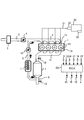
- FIG. 1 is a configuration diagram of a system to which the first embodiment of the present invention is applied.
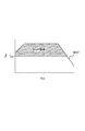
- FIG. 2 is a map showing an operation region in which EGR is executed.
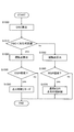
- FIG. 3 is a flowchart for ignition timing control performed by the ECU during execution of EGR.
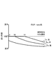
- FIG. 4 is a diagram showing an example of the relationship between the NOx concentration in the intake pipe and the ignition timing for preventing knocking.
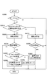
- FIG. 5 is a flowchart for setting the ignition timing retard amount corresponding to the purification performance of the catalyst in the first embodiment.
- FIG. 6 is a block diagram of a system to which the second embodiment of the present invention is applied.
- FIG. 7 is a flowchart for setting the ignition timing retard amount corresponding to the purification performance of the catalyst in the second embodiment.
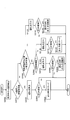
- FIG. 8 is a flowchart for setting the ignition timing retard amount corresponding to the purification performance of the catalyst in the third embodiment.
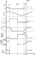
- FIG. 9 is a time chart when the control routine of FIG. 8 is executed.
- FIG. 1 is a configuration diagram of a system to which the first embodiment of the present invention is applied.
- An intake manifold 2 and an exhaust manifold 12 are attached to the internal combustion engine 1.
- An intake passage 5 and an EGR pipe 9 (exhaust gas recirculation device) are connected to the intake manifold 2.
- An exhaust passage 8 is connected to the exhaust manifold 12.
- An air flow meter 3 for measuring the intake air amount and a throttle chamber 4 for adjusting the intake air amount on the downstream side thereof are interposed in the intake passage 5.
- a three-way catalyst 7 for exhaust purification is interposed in the exhaust passage 8, and an A / F sensor 18 is provided on the upstream side of the three-way catalyst 7, and an O 2 sensor 13 is provided on the downstream side.
- the EGR pipe 9 is a passage for returning a part of the exhaust gas that has passed through the three-way catalyst 7 to the intake passage 5 as EGR gas.
- the downstream side of the throttle chamber 4 is communicated.
- the EGR pipe 9 is provided with an EGR cooler 11 that cools the EGR gas flowing inside, and an EGR valve 10 that adjusts the flow rate of the EGR gas. Note that the EGR cooler 11 is not essential.
- Detection values of the A / F sensor 18 and the O 2 sensor 13 are input to an engine control unit (ECU) 20.
- the detected value of the crank angle sensor 14 for detecting the rotational speed Ne of the internal combustion engine 1 and the detected values of the accelerator opening sensor 17 and the water temperature sensor 19 are also read into the ECU 20.
- the ECU 20 controls the opening degree of the throttle chamber 4, the injection amount and injection timing control of the fuel injection valve 15, the ignition timing control of the spark plug 16 as ignition timing control means, and the opening degree of the EGR valve 10.
- Various controls such as control are executed.
- the fuel injection valve 15 is installed in the branch 6 of the intake manifold 2 connected to each cylinder of the internal combustion engine 1.
- the fuel in the fuel tank 30 is supplied to the fuel injection valve 15 via the fuel supply pipe 31 by the fuel pump 32.
- ECU20 is comprised with the microcomputer provided with the central processing unit (CPU), the read-only memory (ROM), the random access memory (RAM), and the input / output interface (I / O interface).
- the ECU 20 can also be composed of a plurality of microcomputers.
- the internal combustion engine 1 which is not provided with a supercharger is demonstrated here, this invention is applicable similarly even if it is an internal combustion engine provided with a turbo-type supercharger and another supercharger.
- 1 is a so-called port injection type in which the fuel injection valve 15 is attached to the intake manifold 2, but it may be a direct injection type in which fuel is directly injected into the cylinder.
- FIG. 2 is a map showing an operation region in which EGR is executed. 2
- the vertical axis represents the torque of the internal combustion engine 1
- the horizontal axis represents the rotational speed Ne of the internal combustion engine 1
- the full load line is indicated by a solid line WOT.
- the EGR is executed in the shaded area in the figure, that is, the area where the torque is equal to or higher than Te1.
- NOx contained in the exhaust gas discharged from the internal combustion engine 1 has a characteristic of easily causing knocking. For this reason, when the NOx concentration in the exhaust gas is high, knocking is more likely to occur by increasing the EGR rate. Therefore, as will be described later, knocking during execution of EGR is prevented by retarding the ignition timing in accordance with the NOx concentration in the EGR gas.
- FIG. 3 is a flowchart showing an ignition timing control routine performed by the ECU 20 during execution of EGR.
- EGR is not executed, control is performed so that the optimal ignition timing (MBT) is reached, as in the known ignition timing control.
- MBT optimal ignition timing
- step S100 the ECU 20 reads the torque of the internal combustion engine 1.
- a required torque obtained based on the accelerator opening and the engine rotational speed Ne may be used, or a generated torque estimated based on the intake air amount may be used.
- step S110 the ECU 20 estimates the NOx concentration in the intake pipe as NOx concentration estimating means.
- the intake pipe NOx concentration is estimated based on, for example, the state of ⁇ control of the air-fuel ratio and the amount of NOx purified by the three-way catalyst 7.
- ⁇ control the air-fuel ratio is enriched or leaned according to the detected value of the A / F sensor 18, so the amount of NOx discharged from the internal combustion engine 1 is stoichiometric if the air-fuel ratio is enriched. If the air-fuel ratio is leaner, it can be estimated that the air-fuel ratio is greater than the stoichiometric state.
- the NOx discharged from the internal combustion engine 1 is removed by the three-way catalyst 7, but the amount of NOx removed by the three-way catalyst 7 can be obtained in advance by experiments or the like.
- the NOx concentration in the exhaust gas discharged from the internal combustion engine 1 at the time of stoichiometry is obtained in advance, and this is corrected based on the rich degree and the lean degree detected by the A / F sensor 18, and then the three-way catalyst 7
- the NOx concentration in the intake pipe is estimated by removing the amount of NOx purified in step. Further, based on the ignition timing, the NOx concentration may be corrected to be higher as the ignition timing is earlier.
- a sensor that directly detects the NOx concentration can also be used.
- step S120 the ECU 20 performs ignition timing control according to the NOx concentration in the intake pipe.
- the relationship between the intake pipe NOx concentration and the ignition timing will be described.
- FIG. 4 is a diagram showing an example of the relationship between the NOx concentration in the intake pipe and the ignition timing for preventing knocking.
- the vertical axis represents the ignition timing
- the horizontal axis represents the NOx concentration in the intake pipe.
- the ignition timing on the vertical axis indicates the degree of deviation from MBT.
- the increase rate of the ignition timing retard amount with respect to the change amount of the NOx concentration that is, the slope of the solid line in FIG. 4 increases as the torque decreases. This is because the lower the torque is, the more difficult the knocking occurs in the combustion chamber, so the effect of increasing the NOx concentration is relatively large. The higher the torque is, the more likely the knocking occurs in the combustion chamber, so the NOx concentration increases. This is because the influence is relatively small.
- the ECU 20 determines the ignition timing from the NOx concentration in the intake pipe estimated in step S110 based on the above-described relationship between the NOx concentration in the intake pipe and the ignition timing.
- the above-described estimation of the NOx concentration in the intake pipe by the A / F sensor 18 can be carried out on the premise that the purification performance of the three-way catalyst 7 has not deteriorated.
- the purification performance of the catalyst 7 is reduced, the amount of NOx purified by the three-way catalyst 7 is reduced, and the NOx concentration in the exhaust gas after passing through the three-way catalyst 7 is greatly increased. It becomes difficult to grasp the NOx concentration.
- the ECU 20 determines whether or not the purification performance of the three-way catalyst 7 is lowered in parallel with the ignition timing control of FIG. 3 described above, and if the purification performance is reduced, the ECU 20 of FIG. In step S120, an ignition timing different from the case where the purification performance has not deteriorated is set.
- FIG. 5 is a flowchart of a control routine executed by the ECU 20 in parallel with the ignition timing control of FIG.
- This control routine determines whether or not the purification performance of the three-way catalyst 7 has deteriorated as the purification performance determination means, and if so, retards the ignition timing calculated in step S120 of FIG. Is.
- it demonstrates according to a step.
- step S1000 the ECU 20 calculates the oxygen storage capacity (hereinafter referred to as catalyst OSC capacity) of the three-way catalyst 7 as oxygen storage capacity detection means. Specifically, the calculation is performed based on the air-fuel ratio and the intake air amount of the exhaust gas flowing into the three-way catalyst 7, that is, the detection value of the A / F sensor 18 and the detection value of the air flow meter 3.
- catalyst OSC capacity oxygen storage capacity
- step S1010 the ECU 20 determines whether or not the catalyst OSC capability is lower than a preset deterioration determination value. If it is deteriorated, the ECU 20 executes the process of step S1020. If not, step S1060 is performed. Execute the process.
- the deterioration judgment value is, for example, the catalyst OSC capability in a state where the guaranteed years and distance of the purification performance required by the exhaust regulations have passed.
- a deterioration determination value is set for each combination of a vehicle type to which the present system is applied, the internal combustion engine 1 and a transmission (not shown).
- step S1020 the ECU 20 calculates an operating point determined from the torque and the rotational speed Ne of the internal combustion engine 1.
- step S1030 the ECU 20 determines whether or not the current operating point is within the EGR region shown in FIG. If it is within the EGR area, the process of step S1040 is executed, and if it is outside the EGR area, the current routine is terminated.
- step S1040 the ECU 20 estimates the NOx concentration in the intake pipe based on the detected value of the A / F sensor 18, and sets the ignition timing retard amount based on the estimated value. That is, when the catalyst OSC capacity is not reduced, the NOx concentration of the exhaust gas before passing through the three-way catalyst 7 estimated based on the detection value of the A / F sensor 18 and the amount of NOx purified by the three-way catalyst 7 From the above, the NOx concentration of the exhaust gas after passing through the three-way catalyst 7 is estimated and the ignition timing retard amount is set, whereas if it is lower, it is based on the NOx concentration of the exhaust gas before passing through the three-way catalyst 7. Set the ignition timing retard amount.
- step S1040 the ignition timing retarded to prevent knocking is set based on the NOx concentration estimated based on the detection value of the A / F sensor 18, and this is set to the ignition timing set in step S120 of FIG. You may make it replace with.
- step S1010 determines whether the catalyst OSC capacity has not deteriorated. If it is determined in step S1010 that the catalyst OSC capacity has not deteriorated, the same processing as in steps S1020 and S1030 is performed in step S1050 and step S1060. In the case of the EGR region, the processing in step S1070 is performed. To do.
- step S1070 the ECU 20 determines execution of ignition timing control in the EGR region during normal operation.
- the normal operation here refers to an operation in a state where the three-way catalyst 7 is not deteriorated. That is, in step S1070, it is determined that the ignition timing set in step S120 of FIG.
- the ignition timing retard amount in the EGR region is calculated based on the detected value of the A / F sensor 18 and the NOx amount purified by the three-way catalyst 7 during normal operation. Set according to the concentration.
- the catalyst OSC capability of the three-way catalyst 7, that is, the purification performance is deteriorated due to aging or the like it is set according to the NOx concentration before passing through the catalyst calculated based on the detection value of the A / F sensor 18. That is, if it is determined that the purification performance of the three-way catalyst 7 has deteriorated, the ignition timing retard amount is set assuming that NOx purification by the three-way catalyst 7 has not been performed at all. Thereby, even when the purification performance of the three-way catalyst 7 is lowered and it is difficult to accurately grasp the NOx concentration, it is possible to reliably avoid the occurrence of knocking.
- the basic system configuration and the control routine shown in FIG. 3 are the same as those in the first embodiment. However, the difference is that a means for detecting the sulfur concentration in the fuel is provided, and that the reduction in the purification performance is due to sulfur poisoning.
- FIG. 6 is a system configuration diagram of this embodiment.
- a sulfur concentration sensor 33 as means for detecting the sulfur concentration in the fuel is installed in the fuel tank 30.
- FIG. 7 is a flowchart of a control routine executed by the ECU 20 in parallel with the ignition timing control of FIG.
- the ECU 20 determines whether or not the purification performance of the three-way catalyst 7 is reduced due to sulfur poisoning as sulfur poisoning determination means, and if so, the calculation is performed in step S120 of FIG. This retards the ignition timing.
- it demonstrates according to a step.
- step S2000 the ECU 20 detects the sulfur concentration in the fuel using the sulfur concentration sensor 33. If sulfur is contained in the fuel at a relatively high concentration, the sulfur component in the exhaust accumulates in the three-way catalyst 7 and the oxygen adsorption and release functions of the three-way catalyst 7 are hindered. The OSC capability is reduced. Therefore, first, the sulfur concentration in the fuel is detected. The detected sulfur concentration is stored until the next operation.
- step S2010 the ECU 20 determines whether or not the sulfur concentration is higher than the poisoning determination value.
- the poisoning determination value a concentration at which sulfur poisoning is surely generated if the fuel is operated is set in advance.
- ECU20 performs the process of step S2020 when the sulfur concentration is higher than the poisoning determination value, and executes the process of step S2050 when the sulfur concentration is low.
- steps S2030 to S2040 is the same as that of steps S1020 to S1040 in FIG.
- step S2050 the ECU 20 determines whether or not the sulfur concentration in the fuel during the previous operation is higher than the poisoning determination value. If it is higher, the process of step S2060 is executed, and if it is lower, the process of step S2130 is executed.
- step S2060 the ECU 20 determines whether or not the sulfur poisoning release condition is satisfied.
- the sulfur poisoning release condition is, for example, that the catalyst temperature has reached a predetermined value or more during the current operation, there is a rich operation period during which the air-fuel ratio can be released, or the current operation time is released from poisoning It is established when enough time has passed. It should be noted that the current operation time becomes the condition for canceling poisoning even if sulfur poisoning has occurred during the previous operation, if the fuel is operated with a fuel having a sulfur concentration lower than the current poisoning judgment value, This is because the poison is released.
- step S2070 If the sulfur poisoning release condition is satisfied, the process of step S2070 is executed, and if not, the process of step S2100 is executed.
- steps S2070 to S2090 is the same as that in steps S1050 to S1070 in FIG.
- steps S2100 to S2120 is the same as that in steps S2020 to S2040, that is, steps S1020 to S1040 in FIG.
- steps S2130 to S2150 is the same as that in steps S2070 to S2090, that is, steps S1050 to S1070 in FIG.
- the normal operation here means an operation in a state where the three-way catalyst 7 is not deteriorated, as in the first embodiment.
- the sulfur concentration in the fuel during the current operation is lower than the poisoning judgment value, it is determined whether or not the sulfur concentration in the fuel used during the previous operation is higher than the poisoning judgment value. If it is lower than the determination value, the ignition timing similar to that during normal operation is set (steps S2010, S2050, S2130-S2150). This is because, in both the previous operation and the current operation, when the sulfur concentration in the fuel is lower than the poisoning determination value, it can be estimated that the three-way catalyst 7 is not poisoned. However, knocking does not occur.
- step S2010, S2050-S2090 the ignition timing similar to that during normal operation is set. This is because even if sulfur poisoning was performed during the previous operation, the sulfur poisoning has been released and knocking does not occur even at the same ignition timing as during normal operation.
- the poisoning release condition is not satisfied, the three-way catalyst 7 remains poisoned from the previous operation and is in a state where knocking is likely to occur. Therefore, based on the NOx concentration in the exhaust before passing through the catalyst, An ignition timing retard amount larger than that during operation is set (steps S2010, S2050, S2100-S2120).
- the ignition timing retard amount in the EGR region is calculated based on the detected value of the A / F sensor 18 and the NOx amount purified by the three-way catalyst 7 during normal operation. Set according to the concentration.
- the catalyst OSC capability of the three-way catalyst 7, that is, the purification performance deteriorates due to sulfur poisoning it is set according to the NOx concentration before passing through the catalyst calculated based on the detection value of the A / F sensor 18. That is, when it is determined that the purification performance of the three-way catalyst 7 is deteriorated due to sulfur poisoning, the ignition timing retard amount is set assuming that NOx purification by the three-way catalyst 7 is not performed at all.
- the poisoning state of the three-way catalyst 7 may be estimated or directly detected.
- the basic system configuration and the control routine shown in FIG. 3 are the same as those in the first embodiment. However, the difference is that the reduction in the purification performance is due to excess oxygen inside the catalyst.
- the reduction in the purification performance due to excessive oxygen is, for example, a state in which fresh air passes through the internal combustion engine 1 and flows into the three-way catalyst 7 as in fuel cut control, for example, and the oxygen storage amount of the three-way catalyst 7 This means that NOx cannot be reduced after the fuel cut is recovered.
- FIG. 8 is a flowchart of a control routine executed by the ECU 20 in parallel with the ignition timing control of FIG.
- the ECU 20 determines whether or not the purification performance of the three-way catalyst 7 as the catalyst atmosphere detection means is reduced due to excessive oxygen, and if so, the calculation is performed in step S120 of FIG.
- the ignition timing is retarded.
- it demonstrates according to a step.
- step S3000 the ECU 20 determines whether or not the fuel cut has been recovered, that is, whether or not the fuel cut control has returned from the deceleration. If it has returned, the process of step S3010 is executed, and if it has not returned, the process of step S3070 is executed.
- step S3010 the ECU 20 determines whether the output of the O 2 sensor 13 is smaller than the excess oxygen determination value.
- an oxygen excess determination region having a width of about 50 mV on each of the rich side and the lean side may be used.
- step S3020 if the output of the O 2 sensor 13 is smaller than the excess oxygen determination value, the process of step S3020 is executed. If the output is greater than the excess oxygen determination value, the process of step S3070 is executed.
- steps S3020 and S3030 the ECU 20 executes the same processing as steps S1020 and S1030 in FIG.
- step S3030 If the result of determination in step S3030 is that it is in the EGR area, processing in step S3040 is executed, and if it is not in the EGR area, this routine is terminated.
- step S3040 the ECU 20 determines whether the output of the A / F sensor 18 is smaller than the A / F determination value.
- step S3050 is executed, and if stoichiometric or lean, the process of step S3060 is executed.
- step S3050 or step S3060 the ECU 20 sets a larger ignition timing retard amount than that during normal operation. That is, if the inside of the three-way catalyst 7 is in an excessive oxygen state, it is assumed that the purification performance has deteriorated, and an ignition timing retard amount larger than that in the normal operation is set based on the NOx concentration at the catalyst inlet. However, the ignition timing retard amount set in step S3050 is smaller than the ignition timing retard amount set in step S3060.
- the setting of the ignition timing retard amount will be described.
- the fact that the catalyst inlet side is rich means that the NOx concentration is lower than in the case of stoichiometric or lean. Therefore, the state of step S3050 in which the catalyst inlet side is rich and the catalyst outlet side is lean has a lower NOx concentration on the catalyst outlet side than the state of step S3060 in which the catalyst inlet side and the outlet side are lean. That is, the state of step S3050 has a lower intake pipe NOx concentration than the state of step S3060, and knocking is less likely to occur. Therefore, the ignition timing is set to the advance side in a state where knocking is difficult to occur compared to a state where knocking is likely to occur.
- the ECU 20 executes the same processing as that of steps S1020 and S1030 of FIG. 5 in steps S3070 and S3080. If it is determined in step S3080 that the region is an EGR region, the processing in step S3090 is executed. If the region is not an EGR region, the current routine is terminated.
- FIG. 9 is a time chart when this control routine is executed.
- the air-fuel ratio at the catalyst inlet becomes rich. This is because the ECU 20 as the rich spike execution means executes the rich spike in order to quickly return the three-way catalyst 7 from the excessive oxygen state to the stoichiometric state. Even during the rich spike, the oxygen stored in the three-way catalyst 7 is released, so the air-fuel ratio at the catalyst outlet remains lean. Moreover, since the oxygen excess inside the three-way catalyst 7 is not eliminated, the NOx concentration at the catalyst outlet increases. The ignition timing is retarded compared to before the fuel cut.
- step S3050 in FIG. 7 is performed.
- the ignition timing is retarded as compared with the normal operation, but the ignition timing on the advance side is set as compared with the case where the operation is performed in the excessive oxygen state and the stoichiometric air-fuel ratio.
- the ignition timing is set based on the NOx concentration at the catalyst inlet, assuming that the purification performance has deteriorated. As a result, the ignition timing retarded from the normal operation is set, so that the occurrence of knocking can be prevented.
- the operation is performed at the stoichiometric air-fuel ratio in the excessive oxygen state.
- the ignition timing on the more advanced side in other words, a smaller ignition timing retard amount is set. As a result, the ignition timing is retarded more than necessary, and the output is not reduced and the fuel consumption is not deteriorated.
Landscapes
- Engineering & Computer Science (AREA)
- Chemical & Material Sciences (AREA)
- Combustion & Propulsion (AREA)
- Mechanical Engineering (AREA)
- General Engineering & Computer Science (AREA)
- Signal Processing (AREA)
- Theoretical Computer Science (AREA)
- Electrical Control Of Ignition Timing (AREA)
- Exhaust Gas After Treatment (AREA)
- Combined Controls Of Internal Combustion Engines (AREA)
- Output Control And Ontrol Of Special Type Engine (AREA)
- Exhaust-Gas Circulating Devices (AREA)
Abstract
Description
第2実施形態は、基本的なシステムの構成及び図3に示した制御ルーチンは第1実施形態と同様である。ただし、燃料中の硫黄濃度を検出する手段を備える点と、対象とする浄化性能の低下が硫黄被毒によるものである点が異なる。
第3実施形態は、基本的なシステムの構成及び図3に示した制御ルーチンは第1実施形態と同様である。ただし、対象とする浄化性能の低下が触媒内部の酸素過多によるものである点が異なる。酸素過多による浄化性能の低下とは、例えば燃料カット制御中のように、新気がそのまま内燃機関1を通過して三元触媒7に流入する状態が続いて、三元触媒7の酸素ストレージ量が過多になり、燃料カットリカバー後にNOxを還元できなくなることをいう。
Claims (6)
- 排気浄化用の触媒を通過した排気ガスを吸気通路へ還流させ得る排気還流装置と、
排気還流実行中は吸気管内NOx濃度に応じてノッキングを防止し得る点火時期リタード量を設定する点火時期制御手段と、
排気ガス中のNOx濃度を推定するNOx濃度推定手段と、
前記触媒の浄化性能の低下を判定する浄化性能低下判定手段と、
を備え、
前記触媒の浄化性能が予め設定した状態まで低下したと前記浄化性能低下判定手段が判定した場合には、前記点火時期制御手段は前記触媒を通過する前の排気ガス中のNOx濃度に基づいて点火時期リタード量を設定する火花点火式内燃機関。 - 請求項1に記載の火花点火式内燃機関において、
前記点火時期制御手段は、前記触媒の浄化性能が低下していない場合には前記触媒通過後の排気ガス中のNOx濃度に基づいて点火時期リタード量を設定する火花点火式内燃機関。 - 請求項1に記載の火花点火式内燃機関において、
前記触媒の酸素ストレージ能力を検知する酸素ストレージ能力検知手段をさらに備え、
前記浄化性能判定手段は、酸素ストレージ能力が予め設定した状態まで低下したら浄化性能が低下したと判定する火花点火式内燃機関。 - 請求項1に記載の火花点火式内燃機関において、
前記触媒が硫黄被毒しているか否かを判定する硫黄被毒判定手段をさらに備え、
前記浄化性能判定手段は、硫黄被毒判定手段で硫黄被毒が発生していると判定した場合に浄化性能が低下したと判定する火花点火式内燃機関。 - 請求項1に記載の火花点火式内燃機関において、
前記触媒内の雰囲気を検知する触媒内雰囲気検知手段をさらに備え、
前記浄化性能判定手段は、触媒内が酸素過多状態の場合には浄化性能が低下したと判定する火花点火式内燃機関。 - 請求項5に記載の火花点火式内燃機関において、
前記触媒内を酸素過多状態からストイキ状態にするためにリッチスパイクを実行するリッチスパイク実行手段をさらに備え、
前記点火時期制御手段は、酸素過多状態かつリッチスパイク実行中には、酸素過多状態かつストイキ空燃比運転中に比べて小さい点火時期リタード量を設定する火花点火式内燃機関。
Priority Applications (4)
| Application Number | Priority Date | Filing Date | Title |
|---|---|---|---|
| JP2013540695A JP5754512B2 (ja) | 2011-10-24 | 2012-09-10 | 火花点火式内燃機関及び火花点火式内燃機関の制御方法 |
| CN201280052135.1A CN104024608B (zh) | 2011-10-24 | 2012-09-10 | 火花点火式内燃机及火花点火式内燃机的控制方法 |
| US14/353,642 US9291143B2 (en) | 2011-10-24 | 2012-09-10 | Spark ignition internal combustion engine and control method of spark ignition internal combustion engine |
| EP12844624.2A EP2772628A4 (en) | 2011-10-24 | 2012-09-10 | CONTROL DEVICE FOR AN INTERNAL COMBUSTION ENGINE WITH SPARK PLUG |
Applications Claiming Priority (2)
| Application Number | Priority Date | Filing Date | Title |
|---|---|---|---|
| JP2011-232678 | 2011-10-24 | ||
| JP2011232678 | 2011-10-24 |
Publications (1)
| Publication Number | Publication Date |
|---|---|
| WO2013061697A1 true WO2013061697A1 (ja) | 2013-05-02 |
Family
ID=48167536
Family Applications (1)
| Application Number | Title | Priority Date | Filing Date |
|---|---|---|---|
| PCT/JP2012/073044 Ceased WO2013061697A1 (ja) | 2011-10-24 | 2012-09-10 | 火花点火式内燃機関の制御装置 |
Country Status (5)
| Country | Link |
|---|---|
| US (1) | US9291143B2 (ja) |
| EP (1) | EP2772628A4 (ja) |
| JP (1) | JP5754512B2 (ja) |
| CN (1) | CN104024608B (ja) |
| WO (1) | WO2013061697A1 (ja) |
Cited By (2)
| Publication number | Priority date | Publication date | Assignee | Title |
|---|---|---|---|---|
| JP2016023617A (ja) * | 2014-07-23 | 2016-02-08 | トヨタ自動車株式会社 | 内燃機関の排気浄化装置 |
| KR20190014530A (ko) * | 2016-05-24 | 2019-02-12 | 크린테크 스위스 아게 | 엔진 작동 장치 |
Families Citing this family (8)
| Publication number | Priority date | Publication date | Assignee | Title |
|---|---|---|---|---|
| KR101551017B1 (ko) * | 2013-12-18 | 2015-09-07 | 현대자동차주식회사 | 차량의 배기가스 정화 시스템 |
| JP6269518B2 (ja) * | 2014-01-22 | 2018-01-31 | トヨタ自動車株式会社 | エンジン制御装置 |
| JP6462311B2 (ja) * | 2014-10-24 | 2019-01-30 | 日立オートモティブシステムズ株式会社 | エンジンの制御装置 |
| JP6156593B2 (ja) * | 2014-12-02 | 2017-07-05 | 日産自動車株式会社 | 内燃機関の制御装置 |
| DE102015007163A1 (de) * | 2015-06-03 | 2016-12-08 | Man Truck & Bus Ag | Betriebsverfahren für eine Abgasreinigungsanlage und entsprechendes Antriebssystem |
| EP3397852B1 (en) | 2015-12-30 | 2025-05-07 | Cummins, Inc. | Control strategies for lean burn spark ignition engines |
| JP7226645B1 (ja) * | 2021-04-15 | 2023-02-21 | 日産自動車株式会社 | 内燃機関の制御方法および制御装置 |
| US12085035B2 (en) * | 2022-11-15 | 2024-09-10 | GM Global Technology Operations LLC | Method and system for evaluating a NOx sensor |
Citations (4)
| Publication number | Priority date | Publication date | Assignee | Title |
|---|---|---|---|---|
| JPH0763151A (ja) * | 1993-08-30 | 1995-03-07 | Nissan Motor Co Ltd | 内燃機関の制御装置 |
| JP2000282965A (ja) | 1999-03-31 | 2000-10-10 | Tokyo Gas Co Ltd | 内燃機関の排気再循環装置 |
| JP2000345895A (ja) * | 1999-06-07 | 2000-12-12 | Mitsubishi Electric Corp | 内燃機関の空燃比制御装置 |
| JP2008215213A (ja) * | 2007-03-05 | 2008-09-18 | Toyota Motor Corp | 内燃機関の制御装置 |
Family Cites Families (16)
| Publication number | Priority date | Publication date | Assignee | Title |
|---|---|---|---|---|
| KR0150432B1 (ko) * | 1994-05-10 | 1998-10-01 | 나까무라 유이찌 | 내연엔진의 제어장치 및 제어방법 |
| DE19709395C2 (de) * | 1997-03-07 | 1998-12-24 | Bosch Gmbh Robert | Verfahren zur Klopfregelung in Mehrzylinder-Brennkraftmaschinen |
| US5894725A (en) * | 1997-03-27 | 1999-04-20 | Ford Global Technologies, Inc. | Method and apparatus for maintaining catalyst efficiency of a NOx trap |
| DE19740365A1 (de) * | 1997-09-13 | 1999-03-18 | Bosch Gmbh Robert | Verfahren zur Bestimmung des Zündwinkels in Zündanlagen für Brennkraftmaschinen |
| JPH11241632A (ja) * | 1998-02-25 | 1999-09-07 | Honda Motor Co Ltd | 内燃機関の制御装置 |
| DE19902209A1 (de) * | 1999-01-21 | 2000-07-27 | Bosch Gmbh Robert | Vorrichtung zum Unterdrücken von Motorklopfen einer Brennkraftmaschine |
| DE60024713T2 (de) * | 1999-06-08 | 2006-09-28 | Honda Giken Kogyo K.K. | Abgasreinigungsvorrichtung und Regler für eine Brennkraftmaschine |
| DE19926146A1 (de) * | 1999-06-09 | 2000-12-14 | Volkswagen Ag | Verfahren zur Initiierung und Überwachung einer Entschwefelung von wenigstens einem in einem Abgaskanal einer Verbrennungskraftmaschine angeordneten NOx-Speicherkatalysator |
| DE60008639T2 (de) * | 1999-07-02 | 2005-03-10 | Mitsubishi Jidosha Kogyo K.K. | Abgasreinigungsvorrichtung einer Brennkraftmaschine |
| DE10054005A1 (de) * | 2000-11-01 | 2002-05-08 | Daimler Chrysler Ag | Verfahren zum Betrieb einer Abgasreinigungsanlage mit Stickoxidspeicher |
| JP4576198B2 (ja) * | 2004-10-19 | 2010-11-04 | 三菱重工業株式会社 | Egrシステム付きガスエンジン |
| US7325394B2 (en) * | 2006-04-27 | 2008-02-05 | Ford Global Technologies Llc | System and method for desulfating a NOx trap |
| JP2009047068A (ja) * | 2007-08-20 | 2009-03-05 | Toyota Motor Corp | 内燃機関の制御装置 |
| FI124007B (fi) * | 2008-12-16 | 2014-01-31 | Waertsilae Finland Oy | Menetelmä ja järjestelmä polttomoottorin päästöjen hallitsemiseksi |
| JP4848024B2 (ja) * | 2009-04-21 | 2011-12-28 | 本田技研工業株式会社 | 内燃機関の制御装置 |
| EP2514952A4 (en) * | 2009-12-18 | 2014-02-19 | Honda Motor Co Ltd | CONTROL DEVICE FOR A COMBUSTION ENGINE |
-
2012
- 2012-09-10 US US14/353,642 patent/US9291143B2/en not_active Expired - Fee Related
- 2012-09-10 WO PCT/JP2012/073044 patent/WO2013061697A1/ja not_active Ceased
- 2012-09-10 CN CN201280052135.1A patent/CN104024608B/zh not_active Expired - Fee Related
- 2012-09-10 EP EP12844624.2A patent/EP2772628A4/en not_active Withdrawn
- 2012-09-10 JP JP2013540695A patent/JP5754512B2/ja not_active Expired - Fee Related
Patent Citations (4)
| Publication number | Priority date | Publication date | Assignee | Title |
|---|---|---|---|---|
| JPH0763151A (ja) * | 1993-08-30 | 1995-03-07 | Nissan Motor Co Ltd | 内燃機関の制御装置 |
| JP2000282965A (ja) | 1999-03-31 | 2000-10-10 | Tokyo Gas Co Ltd | 内燃機関の排気再循環装置 |
| JP2000345895A (ja) * | 1999-06-07 | 2000-12-12 | Mitsubishi Electric Corp | 内燃機関の空燃比制御装置 |
| JP2008215213A (ja) * | 2007-03-05 | 2008-09-18 | Toyota Motor Corp | 内燃機関の制御装置 |
Non-Patent Citations (1)
| Title |
|---|
| See also references of EP2772628A4 |
Cited By (3)
| Publication number | Priority date | Publication date | Assignee | Title |
|---|---|---|---|---|
| JP2016023617A (ja) * | 2014-07-23 | 2016-02-08 | トヨタ自動車株式会社 | 内燃機関の排気浄化装置 |
| KR20190014530A (ko) * | 2016-05-24 | 2019-02-12 | 크린테크 스위스 아게 | 엔진 작동 장치 |
| KR102274486B1 (ko) | 2016-05-24 | 2021-07-12 | 크린테크 스위스 아게 | 엔진 작동 장치 |
Also Published As
| Publication number | Publication date |
|---|---|
| JPWO2013061697A1 (ja) | 2015-04-02 |
| US9291143B2 (en) | 2016-03-22 |
| US20140298777A1 (en) | 2014-10-09 |
| JP5754512B2 (ja) | 2015-07-29 |
| EP2772628A1 (en) | 2014-09-03 |
| EP2772628A4 (en) | 2015-06-03 |
| CN104024608B (zh) | 2016-10-05 |
| CN104024608A (zh) | 2014-09-03 |
Similar Documents
| Publication | Publication Date | Title |
|---|---|---|
| JP5754512B2 (ja) | 火花点火式内燃機関及び火花点火式内燃機関の制御方法 | |
| US8266898B2 (en) | Control apparatus for internal combustion engine | |
| US9500110B2 (en) | Exhaust purifying apparatus for internal combustion engine | |
| US20100024399A1 (en) | Exhaust gas control apparatus for internal combustion engine | |
| US8949001B2 (en) | Control apparatus and control method for internal combustion engine | |
| JP3805098B2 (ja) | エンジンの排気ガス浄化制御装置 | |
| US20140331653A1 (en) | Fuel injection system for internal combustion engine | |
| JP3759567B2 (ja) | 触媒劣化状態検出装置 | |
| US6546719B2 (en) | Air-fuel ratio control apparatus of internal combustion engine | |
| US9109524B2 (en) | Controller for internal combustion engine | |
| JP4062729B2 (ja) | 触媒早期暖機システムの異常診断装置 | |
| JP4206702B2 (ja) | 内燃機関の排気浄化装置 | |
| JP2012167556A (ja) | 内燃機関の燃焼制御装置 | |
| JP2005016396A (ja) | 内燃機関の触媒暖機システム | |
| JP2010174818A (ja) | 内燃機関の制御装置 | |
| JP3309776B2 (ja) | 内燃機関の点火時期制御装置 | |
| KR102452681B1 (ko) | 엔진의 소기 제어 시의 배기 가스 저감 방법 | |
| JP6166646B2 (ja) | 内燃機関の制御装置 | |
| JP7758210B2 (ja) | 内燃機関の空燃比制御方法および装置 | |
| JP2008151025A (ja) | 内燃機関の制御装置 | |
| JP2004132230A (ja) | 内燃機関の排気浄化装置 | |
| JP7750633B2 (ja) | 内燃機関の制御装置 | |
| JP4186517B2 (ja) | 内燃機関用エアクリーナの目詰まり検出装置 | |
| US10253720B2 (en) | Control device for internal combustion engine | |
| JP4103456B2 (ja) | 内燃機関の排気浄化装置 |
Legal Events
| Date | Code | Title | Description |
|---|---|---|---|
| 121 | Ep: the epo has been informed by wipo that ep was designated in this application |
Ref document number: 12844624 Country of ref document: EP Kind code of ref document: A1 |
|
| WWE | Wipo information: entry into national phase |
Ref document number: 14353642 Country of ref document: US |
|
| ENP | Entry into the national phase |
Ref document number: 2013540695 Country of ref document: JP Kind code of ref document: A |
|
| NENP | Non-entry into the national phase |
Ref country code: DE |
|
| WWE | Wipo information: entry into national phase |
Ref document number: 2012844624 Country of ref document: EP |