WO2013061761A1 - 二酸化炭素の回収方法及び回収装置 - Google Patents
二酸化炭素の回収方法及び回収装置 Download PDFInfo
- Publication number
- WO2013061761A1 WO2013061761A1 PCT/JP2012/076073 JP2012076073W WO2013061761A1 WO 2013061761 A1 WO2013061761 A1 WO 2013061761A1 JP 2012076073 W JP2012076073 W JP 2012076073W WO 2013061761 A1 WO2013061761 A1 WO 2013061761A1
- Authority
- WO
- WIPO (PCT)
- Prior art keywords
- absorption
- regeneration
- carbon dioxide
- absorbent
- liquid
- Prior art date
- Legal status (The legal status is an assumption and is not a legal conclusion. Google has not performed a legal analysis and makes no representation as to the accuracy of the status listed.)
- Ceased
Links
Images
Classifications
-
- B—PERFORMING OPERATIONS; TRANSPORTING
- B01—PHYSICAL OR CHEMICAL PROCESSES OR APPARATUS IN GENERAL
- B01D—SEPARATION
- B01D53/00—Separation of gases or vapours; Recovering vapours of volatile solvents from gases; Chemical or biological purification of waste gases, e.g. engine exhaust gases, smoke, fumes, flue gases, aerosols
- B01D53/14—Separation of gases or vapours; Recovering vapours of volatile solvents from gases; Chemical or biological purification of waste gases, e.g. engine exhaust gases, smoke, fumes, flue gases, aerosols by absorption
- B01D53/1406—Multiple stage absorption
-
- B—PERFORMING OPERATIONS; TRANSPORTING
- B01—PHYSICAL OR CHEMICAL PROCESSES OR APPARATUS IN GENERAL
- B01D—SEPARATION
- B01D53/00—Separation of gases or vapours; Recovering vapours of volatile solvents from gases; Chemical or biological purification of waste gases, e.g. engine exhaust gases, smoke, fumes, flue gases, aerosols
- B01D53/34—Chemical or biological purification of waste gases
- B01D53/46—Removing components of defined structure
- B01D53/62—Carbon oxides
-
- B—PERFORMING OPERATIONS; TRANSPORTING
- B01—PHYSICAL OR CHEMICAL PROCESSES OR APPARATUS IN GENERAL
- B01D—SEPARATION
- B01D53/00—Separation of gases or vapours; Recovering vapours of volatile solvents from gases; Chemical or biological purification of waste gases, e.g. engine exhaust gases, smoke, fumes, flue gases, aerosols
- B01D53/14—Separation of gases or vapours; Recovering vapours of volatile solvents from gases; Chemical or biological purification of waste gases, e.g. engine exhaust gases, smoke, fumes, flue gases, aerosols by absorption
- B01D53/1425—Regeneration of liquid absorbents
-
- B—PERFORMING OPERATIONS; TRANSPORTING
- B01—PHYSICAL OR CHEMICAL PROCESSES OR APPARATUS IN GENERAL
- B01D—SEPARATION
- B01D53/00—Separation of gases or vapours; Recovering vapours of volatile solvents from gases; Chemical or biological purification of waste gases, e.g. engine exhaust gases, smoke, fumes, flue gases, aerosols
- B01D53/14—Separation of gases or vapours; Recovering vapours of volatile solvents from gases; Chemical or biological purification of waste gases, e.g. engine exhaust gases, smoke, fumes, flue gases, aerosols by absorption
- B01D53/1456—Removing acid components
- B01D53/1475—Removing carbon dioxide
-
- B—PERFORMING OPERATIONS; TRANSPORTING
- B01—PHYSICAL OR CHEMICAL PROCESSES OR APPARATUS IN GENERAL
- B01D—SEPARATION
- B01D2252/00—Absorbents, i.e. solvents and liquid materials for gas absorption
- B01D2252/20—Organic absorbents
- B01D2252/204—Amines
-
- B—PERFORMING OPERATIONS; TRANSPORTING
- B01—PHYSICAL OR CHEMICAL PROCESSES OR APPARATUS IN GENERAL
- B01D—SEPARATION
- B01D2252/00—Absorbents, i.e. solvents and liquid materials for gas absorption
- B01D2252/20—Organic absorbents
- B01D2252/204—Amines
- B01D2252/20478—Alkanolamines
- B01D2252/20484—Alkanolamines with one hydroxyl group
-
- B—PERFORMING OPERATIONS; TRANSPORTING
- B01—PHYSICAL OR CHEMICAL PROCESSES OR APPARATUS IN GENERAL
- B01D—SEPARATION
- B01D2252/00—Absorbents, i.e. solvents and liquid materials for gas absorption
- B01D2252/20—Organic absorbents
- B01D2252/204—Amines
- B01D2252/20478—Alkanolamines
- B01D2252/20489—Alkanolamines with two or more hydroxyl groups
-
- B—PERFORMING OPERATIONS; TRANSPORTING
- B01—PHYSICAL OR CHEMICAL PROCESSES OR APPARATUS IN GENERAL
- B01D—SEPARATION
- B01D2252/00—Absorbents, i.e. solvents and liquid materials for gas absorption
- B01D2252/50—Combinations of absorbents
-
- B—PERFORMING OPERATIONS; TRANSPORTING
- B01—PHYSICAL OR CHEMICAL PROCESSES OR APPARATUS IN GENERAL
- B01D—SEPARATION
- B01D2258/00—Sources of waste gases
- B01D2258/02—Other waste gases
- B01D2258/0283—Flue gases
-
- Y—GENERAL TAGGING OF NEW TECHNOLOGICAL DEVELOPMENTS; GENERAL TAGGING OF CROSS-SECTIONAL TECHNOLOGIES SPANNING OVER SEVERAL SECTIONS OF THE IPC; TECHNICAL SUBJECTS COVERED BY FORMER USPC CROSS-REFERENCE ART COLLECTIONS [XRACs] AND DIGESTS
- Y02—TECHNOLOGIES OR APPLICATIONS FOR MITIGATION OR ADAPTATION AGAINST CLIMATE CHANGE
- Y02C—CAPTURE, STORAGE, SEQUESTRATION OR DISPOSAL OF GREENHOUSE GASES [GHG]
- Y02C20/00—Capture or disposal of greenhouse gases
- Y02C20/40—Capture or disposal of greenhouse gases of CO2
Definitions
- the present invention relates to a carbon dioxide recovery method and recovery device for separating and recovering carbon dioxide from a gas containing carbon dioxide such as combustion gas and reducing clean gas to the atmosphere.
- the absorbent In the chemical absorption method, mainly alkanolamine-based basic compounds are used as the absorbent.
- an aqueous liquid containing the absorbent is generally used as the absorbent, and carbon dioxide contained in the gas is absorbed into the absorbent.
- the absorbing solution is circulated so as to alternately repeat the absorbing step to be performed and the regeneration step of regenerating the absorbing solution by releasing the absorbed carbon dioxide from the absorbing solution (see, for example, Patent Document 1 below).
- heating for releasing carbon dioxide is necessary, and in order to reduce the operating cost of carbon dioxide recovery, it is important to reduce the energy required for heating / cooling for regeneration.
- Patent Document 2 For the purpose of reducing energy required for recovering carbon dioxide from the absorbing liquid, in Patent Document 2 below, steam condensed water generated from a regenerative heater for extracting the absorbing liquid in the regeneration process and exchanging heat with high-temperature steam is used. The remaining heat is used for heating the absorbent. Furthermore, in the following Patent Document 3, it is described that a stripping gas is introduced so as to accompany carbon dioxide in order to promote the release of absorbed carbon dioxide.
- the energy required in the regeneration process includes sensible heat required to raise the temperature of the absorbing solution, reaction heat when releasing carbon dioxide from the absorbing solution, and latent heat to compensate for heat loss due to moisture evaporation of the absorbing solution. is there.
- the above-described prior art is a technique related to sensible heat or reaction heat, and energy related to latent heat is discharged together with water vapor contained in the recovered carbon dioxide. Therefore, there is still room for improvement in energy efficiency.
- An object of the present invention is to provide a carbon dioxide recovery method and a recovery apparatus that can solve the above-described problems and reduce the energy required for regenerating the absorbing liquid to reduce the operation cost.
- Another object of the present invention is to reduce the burden on the apparatus and the absorption liquid, reduce the energy required for regeneration of the absorption liquid without reducing the carbon dioxide recovery rate, and reduce the carbon dioxide recovery cost. It is to provide a carbon recovery method and a recovery apparatus.
- the present inventors have conducted extensive research and as a result, the absorption process and the regeneration process are each divided into at least two stages, and the absorption liquid is circulated using a circulation system separated into two.
- the present invention has been completed by finding that it is configured to carry out two sets of carbon dioxide absorption / recovery cycles.
- the carbon dioxide recovery device is an absorption tower that causes gas to contact the absorption liquid and absorb the carbon dioxide contained in the gas into the absorption liquid, the first absorption section and the second absorption.
- the absorption tower arranged to be supplied to the second absorption section through the first absorption section, and the absorption liquid that has absorbed carbon dioxide in the absorption tower,
- a regeneration tower for regenerating by releasing carbon dioxide, comprising a first regeneration unit and a second regeneration unit, wherein the first regeneration unit has external heating means, and the second regeneration unit is the first regeneration
- a first circulation path that circulates an absorbing liquid between the regeneration tower arranged to be heated by the heat of gas emitted from the section, the first absorption section and the second regeneration section, and Circulation having a second circulation path for circulating the absorbing liquid between the second absorption part and the first regeneration part
- Circulation having a second circulation path for circulating the absorbing liquid between the second absorption part and the first regeneration part
- the method for recovering carbon dioxide is an absorption process in which gas is brought into contact with an absorbing liquid and carbon dioxide contained in the gas is absorbed into the absorbing liquid. 2 absorption steps, and the gas heats the absorption treatment supplied to the second absorption step through the first absorption step and the absorption liquid that has absorbed carbon dioxide in the absorption treatment to release carbon dioxide.
- the regeneration treatment heated by the heat of the released gas, a first circulation step of circulating an absorbent between the first absorption step and the second regeneration step, the second absorption step and the first
- the second circulation in which the absorbing liquid is circulated between the regeneration process And summarized in that a step.
- the recovery efficiency of heat used for regeneration of the absorbing liquid is improved, and the thermal energy required for regeneration is reduced without reducing the recovery rate of carbon dioxide. Therefore, it is possible to provide a carbon dioxide recovery method and a recovery device that are effective in reducing operation costs.
- Two absorption liquids with different compositions can be used, and the characteristics of the absorption liquid can be specialized according to the absorption / regeneration conditions of each absorption liquid. Utilizing these characteristics, the carbon dioxide recovery and absorption liquid Can be efficiently performed, reducing the load during regeneration on the absorption liquid and using the absorption liquid efficiently and stably, which is effective in reducing operating costs and equipment maintenance costs. . It is economically advantageous because it can be carried out easily using general equipment without requiring special equipment or expensive equipment.
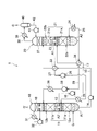
- FIG. 1 is a schematic configuration diagram showing an embodiment of a carbon dioxide recovery apparatus according to the present invention.
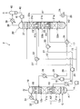
- FIG. 2 is a schematic configuration diagram showing another embodiment of the carbon dioxide recovery apparatus according to the present invention.
- absorption treatment that absorbs carbon dioxide contained in the gas into a low-temperature absorption liquid and high-temperature regeneration that regenerates the absorption liquid by releasing the absorbed carbon dioxide from the absorption liquid
- the absorption liquid is circulated between the treatments, and the absorption treatment and the regeneration treatment are alternately repeated.
- the regeneration rate of the absorbent in the regeneration process depends on the heating temperature of the absorbent, and the higher the temperature, the more carbon dioxide gas is released and the residual carbon dioxide concentration in the absorbent becomes lower (see: Jong I. Lee, Frederick D. Otto and Alan E. Mather, "EquilibriumetBetween carbon Dioxide and Aqueous Monoethanolamine Solutions", J.sappl.
- the absorbing liquid in the regeneration process is maintained near the boiling temperature by external heating means using thermal energy supplied from an external heat source.
- the high-temperature regenerated absorbent (lean liquid) that has released carbon dioxide in the regeneration process exchanges heat with the absorbent (rich liquid) that has absorbed carbon dioxide in the absorption process, so that the heated rich liquid is supplied to the regenerative process. Heat energy is recovered and reused.
- the gas containing carbon dioxide released from the absorbing solution in the regeneration process is discharged in a high temperature state including the heat, and the amount of heat contained in the exhaust gas is wasted.
- the temperature of the exhaust gas can be lowered, that is, the temperature at the top of the regeneration tower can be lowered by lowering the heat exchange rate between the rich liquid and the lean liquid, but the sensible heat recovered in the heat exchange is reduced. Therefore, it does not contribute to the reduction of heat.
- the absorption process and the regeneration process are each divided into at least two stages to constitute two sets of absorption process and regeneration process, and the circulation path for circulating the absorbent is also separated into two independent paths.
- the absorption liquid is circulated between the pair of absorption process and regeneration process.
- the absorbing liquid is positively heated by an external heating means using an external energy source.
- the high-temperature gas released in this process is supplied to another regeneration process and becomes a heat source.
- the absorbent is regenerated by heating. That is, the heat recovered from the gas is directly used for the regeneration of the absorbent.
- each of the absorbents circulating in the two routes can be individually selected, so that each of the absorption liquids can be adjusted to a suitable characteristic according to the processing conditions in the route, and 2 prepared in different compositions. It is also possible to use different types of absorbents. In general, it is difficult to develop an absorbent that is excellent in both absorption and regenerative properties, and it is generally excellent in either one. In the configuration in which the liquid can be used, the energy required for regeneration can be reduced while avoiding a decrease in absorption efficiency and regeneration efficiency by selecting and using an absorption liquid specialized for the processing conditions of the absorption process and regeneration process of each circulation system. Reduction can be advantageously promoted.
- FIG. 1 shows an embodiment of the carbon dioxide recovery apparatus of the present invention.
- the recovery device 1 is configured to bring the gas G containing carbon dioxide into contact with the absorption liquid and absorb the carbon dioxide into the absorption liquid, and heat the absorption liquid that has absorbed the carbon dioxide to release the carbon dioxide from the absorption liquid.
- a regeneration tower 20 for regenerating the absorbent.
- the absorption tower 10 and the regeneration tower 20 are each configured as a countercurrent gas-liquid contact device, and are filled with fillers 11 and 21 for increasing the contact area.
- an aqueous liquid containing a compound having an affinity for carbon dioxide such as alkanolamines as an absorbent is used.
- the fillers 11 and 21 are made of a material having durability at a processing temperature and corrosion resistance, and can be appropriately selected and used in a shape capable of providing a desired contact area. Although those made of an iron-based metal material such as steel are used, it is not particularly limited thereto. Furthermore, if necessary, a cooling tower for maintaining the gas G supplied to the absorption tower 10 at a low temperature suitable for carbon dioxide absorption may be provided.
- the gas G containing carbon dioxide is supplied from the lower part of the absorption tower 10.
- the inside of the absorption tower 10 is partitioned into a lower first absorption part 12a in which the filler 11a is accommodated and an upper second absorption part 12b in which the filler 11b is accommodated, and the first absorption part 12a and the second absorption part 12b.
- a partition member 13 having a tubular wall standing on the periphery of the central hole of the horizontal annular plate is interposed between the absorber 12b and a shade covering the upper end hole of the tubular wall of the partition member 13 so that the absorption tower 10
- a liquid pool is formed on the horizontal annular plate between the inner wall of the partition member 13 and the tubular wall of the partition member 13.
- the absorption liquid is divided into two parts, a first absorption liquid and a second absorption liquid.
- the first absorption liquid is supplied from the upper part of the first absorption part 12a of the absorption tower 10 and flows down the filler 11a, and then the absorption tower.
- the second absorption liquid stored in the bottom 10 is supplied from the upper part of the second absorption part 12b of the absorption tower 10, and stored in the liquid pool of the partition member 13 after flowing down the filler 11b.
- the first absorption liquid (rich liquid) A1 ′ that has absorbed carbon dioxide in the first absorption section 12a is stored at the bottom of the absorption tower 10 and is connected to the bottom of the absorption tower 10 and the top of the regeneration tower 20 by the pump 14. It is supplied to the regeneration tower 20 through the supply path 15.
- the second absorption liquid (rich liquid) A2 ′ that has absorbed carbon dioxide in the second absorption section 12b is stored in the liquid pool of the partition member 13, and the central portion of the absorption tower 10 and the regeneration tower 20 are separated by the pump 16. It is supplied to the regeneration tower 20 through the connected second supply path 17.
- the gas G ′ from which carbon dioxide has been removed is discharged from the top of the absorption tower 10.
- the absorption liquid absorbs carbon dioxide to generate heat and the liquid temperature rises. Therefore, if necessary, a cooling condensing unit 18 for condensing water vapor or the like that can be contained in the gas G ′ is provided at the top of the absorption tower 10. Thereby, it can suppress to some extent that water vapor
- Condensed water or the like cooled by the cooler 31 and supplied to the top of the tower maintains the cooling condensing unit 18 at a low temperature and reliably cools the gas G ′ passing through the cooling condensing unit 18.
- the drive of the pump 32 is controlled so that the temperature of the gas G ′ discharged to the outside of the tower is preferably about 60 ° C. or less, more preferably 45 ° C. or less.
- the water condensed in the cooling condensing unit 18 is supplied to the packing material 11b, but the condensed water can be used to compensate for the composition variation of the absorption liquid in the tower, so the first is necessary.
- the concentration composition of the second absorbing liquid may be detected, and condensed water may be distributed and supplied to the fillers 11a and 11b according to the concentration fluctuation ratio.
- the condensed water in the absorption tower 10 is preferably added to the second absorbent.
- the regeneration tower 20 is partitioned into a lower first regeneration unit 22a in which the filler 21a is accommodated and an upper second regeneration unit 22b in which the filler 21b is accommodated, and the first regeneration unit 22a and the second regeneration unit 22b.
- a partition member 23 that forms a liquid pool with a structure similar to that of the partition member 13 is interposed between the regenerator 22b.
- the first absorbing liquid A1 ′ supplied from the bottom of the absorption tower 10 through the first supply path 15 is introduced into the upper part of the second regeneration section 22b of the regeneration tower 20 and flows down through the packing material 21b, and then pools in the partition member 23. And is led out of the tower without flowing down to the first regeneration section.
- the second absorption liquid A2 ′ supplied from the second absorption part 12b of the absorption tower 10 through the second supply path 17 is supplied to the upper part of the first regeneration part 22a, and flows down the filler 21a and then flows into the bottom part of the regeneration tower 20. Stored.
- a reboiler is attached as an external heating means for actively heating the absorbent using externally supplied energy. That is, a steam heater 24 attached outside the regeneration tower 20 and a circulation path 25 for circulating the second absorbent A2 stored in the tower bottom through the steam heater 24 are attached, and the second absorbent at the bottom of the tower is added. A part of A2 is diverted to the steam heater 24 through the circulation path 25, continuously heated by heat exchange with high-temperature steam, and refluxed into the tower. As a result, the second absorbing liquid A2 at the bottom is actively heated to sufficiently release carbon dioxide, and the filler 21a is also indirectly heated to cause carbon dioxide due to gas-liquid contact on the filler 21a. Release is promoted.
- the high temperature gas containing carbon dioxide and water vapor released from the second absorbing liquid rises and passes through the filler 21a of the first regeneration unit 22a, and then passes through the tubular wall inner hole of the partition member 23 for the second regeneration. It passes through the filler 21b of the part 22b.
- the second absorption liquid A2 'flowing down the filler 21a and the first absorption liquid A1' flowing down the filler 21b are heated, and carbon dioxide in the absorption liquids A1 'and A2' is released.
- the first absorbing liquid A1 ′ supplied to the second regeneration unit 22b is not actively heated by the external heating means, and is heated only by the heat of the gas released from the first regeneration unit 22a. 2 lower than the absorption liquid A2 ′.
- the regeneration degree of the first absorption liquid A1 in the liquid pool of the partition member 23 is lower than the regeneration degree of the second absorption liquid A2 at the bottom of the tower, and is semi-lean.
- the first absorption liquid A1 from which carbon dioxide has been released is supplied to the first absorption tower 10 through the first reflux path 27 that connects the central portion of the regeneration tower 20 and the central portion of the absorption tower 10 by the pump 26 from the pool of the partition member 23. It is refluxed to the upper part of the absorption part 12a.
- the second absorption liquid A2 (lean liquid) that has been stored at the bottom of the regeneration tower 20 and has sufficiently released carbon dioxide is absorbed by the pump 28 through the second reflux path 29 that connects the top of the absorption tower 10 and the bottom of the regeneration tower 20. It is refluxed to the upper part of the second absorption part 12b of the tower 10.
- the first absorption liquids A1 and A1 ′ reciprocate between the first absorption part 12a and the second regeneration part 22b by the first supply path 15 and the first reflux path 27 to form the first circulation system.
- the second absorption liquids A2 and A2 ′ are reciprocated between the second absorption section 12b and the first regeneration section 22a by the second supply path 17 and the second reflux path 29 to form a second circulation system.
- the gas containing carbon dioxide released from the absorbent in the regeneration tower 20 is discharged from the top of the regeneration tower 20.
- the first absorbent A1 from which carbon dioxide has been released by the second regeneration unit 22b passes through the first heat exchanger 33 while refluxing the first reflux path 27, and in the first heat exchanger 33, the first supply path Heat exchange is performed between the first return path 27 and the first return path 27. Therefore, the first absorption liquid A1 is cooled by the first absorption liquid A1 ′ of the first supply passage 15, and further cooled sufficiently to a temperature suitable for absorption of carbon dioxide by the cooler 35 using cooling water. Later, it is introduced into the upper part of the first absorption part 12a.
- the second absorbing liquid A2 from which carbon dioxide has been released by the first regeneration unit 22a passes through the second heat exchanger 34 while flowing through the second reflux path 29, and the second heat exchanger 34 supplies the second supply liquid A2.
- Heat exchange is performed between the path 17 and the second reflux path 29. Accordingly, the second absorption liquid A2 is cooled by the second absorption liquid A2 ′ in the second supply path 17, and after being sufficiently cooled in the same manner by the cooler 36 using cooling water, the second absorption section 12b. Introduced at the top.
- heat exchangers such as spiral type, plate type, double pipe type, multiple cylinder type, multiple circular pipe type, spiral tube type, spiral plate type, tank coil type, tank jacket type, direct contact liquid type, etc.
- the plate type is superior in terms of simplification of the apparatus and ease of cleaning and disassembly.
- the gas containing carbon dioxide released from the absorbing liquid by heating in the regeneration tower 20 passes through the condensing part 37 at the upper part of the regeneration tower 20 and is then discharged from the top through the exhaust pipe 38 and is a cooler using cooling water.
- the water vapor or the like contained by sufficiently cooling by 39 is condensed as much as possible, and the condensed water is removed by the gas-liquid separator 40 and then recovered as the recovered gas C.
- the condensing part 37 condenses the water vapor
- Carbon dioxide contained in the recovered gas C can be fixed and reorganized in the ground by, for example, injecting it into the ground or oil fields.
- the condensed water separated in the gas-liquid separator 40 is supplied from the flow path 42 onto the condensing unit 37 of the regeneration tower 20 by a pump 41 at a predetermined flow rate, and functions as cooling water.
- the temperature of the second absorbent A2 heated at the bottom of the first regenerator 22a is T1, and the second absorbent A2 ′ introduced from the second heat exchanger 34 to the top of the first regenerator 22a. If T2 is T2, then T1> T2. Further, the temperature of the first absorbing liquid A1 in the liquid pool heated in the second regeneration unit 22b by the gas released from the first regeneration unit 22a is set to T3, and is introduced from the first heat exchanger 33 to the second regeneration unit 22b. When the temperature of the first absorbing liquid A1 ′ is T4, the temperature of the gas released from the first regeneration unit 22a to the second regeneration unit 22b is t1, and the temperature of the gas released from the second regeneration unit 22b is t2.
- the absorption liquid in the regeneration tower is heated in the vicinity of the boiling point of the absorption liquid in order to increase the degree of regeneration, and the heat difference is increased by using a heat exchanger having high heat exchange performance to increase the temperature difference (T1-T2).
- T1-T2 the temperature difference
- the temperature t1 of the gas released from the first regeneration unit 22a also increases, and if it is discharged from the regeneration tower 20 as it is, not only sensible heat energy is released, but also a large amount of latent heat energy together with water vapor. Will also be released.
- the amount of heat of the gas released from the first regeneration unit 22a is recovered in the second regeneration unit 22b and used for regeneration of the absorbing liquid, and the temperature of the gas is decreased from t1 to t2 to increase the outside of the sensible heat. Reduce the amount released to As the temperature of the gas decreases, the condensation of water vapor also proceeds, so the water vapor and latent heat contained in the gas released from the second regeneration unit 22b also decrease.
- the condensed water vapor evaporated from the absorption liquid is transferred to the second absorption liquids A2 and A2 ′ of the second absorption section 12b in the absorption tower 10 and the second regeneration section 22b in the regeneration tower 20.
- the vaporization from the second absorption liquid A2 in the first regeneration section 22a exceeds the condensed moisture supplemented in the second absorption section 12b.
- a part of 1st absorption liquid May be mixed with the second absorbent, or a part of the second absorbent may be mixed with the first absorbent.
- the energy loss caused by the partial mixing of the absorbing liquid can be reduced by adjusting the operating conditions (such as the circulating amount of the absorbing liquid), and the first absorbing liquid A1 after regeneration and the second absorbing liquid A2 after absorption. It is advisable to adjust the operating conditions so that the carbon dioxide concentration of 'is approximately the same and mix the absorbent.
- the second absorbing liquid A2 ′ rich liquid in the second supply path 17 from the second heat exchanger 34 to the first regeneration unit 22a is used.
- Carbon dioxide bubbles are likely to be generated due to temperature rise, and the bubbles may hinder heat transfer and prevent the temperature difference (T1-T2) from being reduced.
- foaming can be suppressed by charging the rich liquid into the second heat exchanger 34 in a pressurized state, and the hindrance to the temperature rise of the rich liquid is eliminated.
- the temperature difference between the heat exchanger inlet temperature of the lean liquid and the heat exchanger outlet temperature of the rich liquid is reduced to reflect the heat exchange performance, and the heat energy given by the heat exchanger is efficiently transferred to the regeneration process.
- the temperature difference at the time of heat exchange can be generally set to less than 10 ° C., preferably about 3 ° C., and when the pressure applied to the absorbing liquid is released when it is put into the regeneration process, the release of carbon dioxide is promoted. Also effective.
- the absorbing liquid into the second heat exchanger 34 in a pressurized state for example, on the second supply path 17 between the second heat exchanger 34 and the regeneration tower 20 (for example, to the first regeneration unit 22a).
- the first absorption liquid A1 'supplied to the second regeneration unit 22b while suppressing foaming by pressurization can be easily increased in temperature.
- the pressurized absorbing liquid is released when it is introduced into the regeneration tower, the release of carbon dioxide is promoted and the latent heat is consumed at that time, which also has the effect of contributing to a decrease in the temperature of the emitted gas.
- a gas G containing carbon dioxide such as combustion exhaust gas and process exhaust gas is supplied from the bottom, and the first and second absorption liquids A1 and A2 are respectively supplied from the top of the first and second absorption parts 12a and 12b.
- the gas G and the first and second absorption liquids A1 and A2 come into gas-liquid contact on the fillers 11a and 11b, and carbon dioxide is absorbed by the absorption liquid. Since carbon dioxide is well absorbed at a low temperature, the liquid temperature of the absorbing liquids A1 and A2 or the temperature of the absorption tower 10 (particularly the packing materials 11a and 11b) is generally about 50 ° C. or lower, preferably 40 ° C. or lower. Adjust.
- the gas G supplied to the absorption tower 10 may be adjusted to an appropriate temperature in advance using a cooling tower in consideration of the above.
- aqueous liquids containing a compound having affinity for carbon dioxide as an absorbent are used as the first and second absorbing liquids A1 and A2.
- the absorbent include alkanolamines and hindered amines having an alcoholic hydroxyl group.
- examples of the alkanolamine include monoethanolamine, diethanolamine, triethanolamine, N-methyldiethanolamine (MDEA),
- examples of the hindered amine having an alcoholic hydroxyl group include 2-amino-2-methyl-1-propanol (AMP), 2- (ethylamino) ethanol (EAE), and the like.
- Examples include 2- (methylamino) ethanol (MAE), and a plurality of the above compounds may be used in combination.
- the absorbent concentration of the absorbent can be appropriately set according to the amount of carbon dioxide contained in the gas to be treated, the treatment speed, the fluidity of the absorbent and the suppression of consumption loss, and is generally 10 to 50% by mass. For example, for the treatment of the gas G having a carbon dioxide content of about 20%, an absorbing solution having a concentration of about 30% by mass is preferably used.
- the same absorbing liquid may be used, or 1) the absorbing liquid having a different absorbent concentration, and 2) the type and composition of the absorbing agent are different. It is also possible to use an absorbing solution.
- the heat of the second absorbent A2 is set by setting the absorbent concentration of the second absorbent A2 having a relatively high heating temperature in the regeneration tower 20 to be lower than that of the first absorbent. Since the first absorbent liquid A1 can improve the heat resistance by suppressing alteration, and the absorbent capacity can be increased, the one having good absorbability and regenerative property (reproducibility) from among the absorbents having difficulty in heat resistance Can be selected and used.
- the carbon dioxide concentration of the gas to be processed is higher than that of the second absorption part 12b and the carbon dioxide is easily absorbed, so the first absorption liquid A1 is the absorption liquid.
- the absorbing liquid is selected giving priority to the absorptivity.
- the degree of regeneration at a lower temperature in the second regenerating part 22b is increased, and the absorbing liquid returning to the first absorbing part 12a is made closer to the lean liquid.
- Monoethanolamine (MEA) which is generally preferred for use, is an absorbent having high absorbability, and examples of the absorbent having good regenerative properties include AMP and MDEA.
- MEA is mixed to form an absorption liquid.
- the absorption and regeneration can be adjusted to some extent depending on the mixing ratio. If the 1st and 2nd absorption liquid is prepared using it, absorption and reproduction
- an absorbent solution having a relatively high concentration of MDEA or AMP is used as the first absorbent solution A1
- an absorbent solution having a relatively high MEA concentration and a high absorbability is used as the second absorbent solution A2. Is preferable in terms of reducing the regenerative energy.
- the supply speed of the gas G and the circulation speed of the first and second absorption liquids are determined in consideration of the amount of carbon dioxide contained in the gas G, the carbon dioxide absorption capacity of the absorption liquid, the gas-liquid contact efficiency in the filler, and the like. It is set as appropriate so as to proceed well.
- the absorption process / regeneration process is repeatedly executed by circulation of each absorption liquid.
- the second absorption liquid A2 ′ that has absorbed carbon dioxide is supplied from the second supply path 17 to the first regeneration unit 22a, and during this time, is heated by heat exchange with the second absorption liquid A2 that is refluxed from the regeneration tower 20. Is done.
- the temperature T1 of the second absorbent A2 heated by external heat in the first regeneration unit 22a varies depending on the composition of the absorbent used and the regeneration conditions, but is generally set to about 100 to 130 ° C. (near the boiling point). Based on this, the heat exchanger outlet temperature of the second absorbing liquid A2 ′, that is, the introduction temperature T2 to the second regeneration unit 22a can be about 95 to 125 ° C.
- the temperature t1 of the gas released from the first regeneration unit 22a to the second regeneration unit 22b is about 85 to 115 ° C., and is heated by the second regeneration unit 22b by the gas released from the first regeneration unit 22a.
- the temperature T3 of the first absorbing liquid A1 is about 85 to 115 ° C.
- the temperature T4 of the first absorbent A1 'introduced into the second regeneration unit 22b can be set to about 80 to 110 ° C.
- the temperature t2 of the gas released from the second regeneration unit 22b can be lowered to 100 ° C. or lower.
- the second absorbent A2 stored at the bottom of the regeneration tower 20 is heated to the vicinity of the boiling point by partial circulation heating.
- the boiling point of the absorbent depends on the composition (absorbent concentration) and the pressure in the regeneration tower 20.
- heating it is necessary to supply the latent heat of vaporization of water lost from the absorbing solution and the sensible heat of the absorbing solution.Suppressing the vaporization by pressurization increases the sensible heat by increasing the boiling point. It is preferable in terms of energy efficiency to use a condition setting in which the inside of the regeneration tower 20 is pressurized to about 100 kPaG and the absorbing solution is heated to 120 to 130 ° C.
- the pressurization in the regeneration tower 20 can be adjusted by providing a pressure control valve at the outlet of the exhaust pipe 38 and controlling it.
- the temperature t2 at the top of the regeneration tower 20 can be lowered to a temperature close to the temperature T4 of the first absorbent A1 ′ to be charged. (T2 ⁇ t1, T4 ⁇ T3 ⁇ t1). Therefore, the water vapor and latent heat contained in the recovered gas passing through the condensing unit 37 are reduced, and the loss of thermal energy is reduced.
- the carbon dioxide content of the absorbing solution is high, but the first absorbing solution that contacts the gas having a high carbon dioxide concentration in the first absorbing portion 12a is: Since the carbon dioxide content tends to be relatively high, it is suitable for performing regeneration using recovered heat in the second regeneration unit 22b.
- the first and second absorption liquids A1 and A2 are circulated between the absorption tower 10 and the regeneration tower 20 independently of each other, and are regenerated at a temperature lower than that of the first regeneration section 22a.
- the first and second absorption liquids A1 and A2 can also be regarded as the first absorption liquid A1 as an auxiliary absorption liquid and the second absorption liquid A2 as a main absorption liquid.
- the role of the first absorption liquid A1 includes the reduction of the absorption load given to the second absorption liquid A2 by the gas having a high carbon dioxide concentration, along with the recovery and reuse of thermal energy in the regeneration tower. That is, the apparatus configuration of FIG. 1 is also effective in enhancing the process adaptability of the collection apparatus.
- the first absorption unit and the second regeneration unit are defined as the first absorption unit and the second regeneration unit, which are added when the recovery device is changed to the device structure of FIG. If the absorption liquid of the same quality is circulated between the first regeneration section and the second regeneration section, the regeneration temperature is 106 degrees C., which is 12 degrees C. lower than the absorption liquid introduction temperature to the first regeneration section. The energy can be reduced to about 3.4 GJ / t-CO 2 by the contribution of the decrease in latent heat of vaporization.
- the regeneration energy is 3 It can be reduced to about 1 GJ / t-CO 2 .
- FIG. 2 shows another embodiment of the recovery apparatus for implementing the carbon dioxide recovery method of the present invention.
- the absorption tower 10 has two absorption parts as in FIG. 1, but the regeneration tower 20 ′ has three regeneration parts 22a, 22b, and 22c, and the packing material 21 ′ has three regeneration parts. Loaded into each of the parts.
- a partition member 23 ' having the same structure as the partition members 13 and 23 described above is interposed between the second playback unit 22b and the third playback unit 22c.
- the first absorption liquid A1 ′ that has absorbed carbon dioxide in the first absorption section 12a of the absorption tower 10 is distributed and supplied to each of the second regeneration section 22b and the third regeneration section 22c of the regeneration tower 20 ′, and the first regeneration section.
- the gas released from 22a passes through the second regenerating part 22b, passes through the partition member 23 ', and further contacts the first absorbing liquid A1' on the filler 21c of the third regenerating part 22c.
- the temperature of the released gas is further reduced from the configuration of FIG.
- a third supply path 15 ′ is provided, from which the third regenerating section 22c returns the first absorbing liquid A1c stored in the liquid pool of the partition member 23 ′ from the third regenerating section 22c to the first absorbing section 12a.
- a third reflux path 27 ′ that joins the first reflux path 27 is provided. Furthermore, a third heat exchanger 33 ′ that performs heat exchange between the third supply path 15 ′ and the third reflux path 27 ′ is provided, and the first absorbent A1 ′ that passes through the third supply path 15 ′ After being heated by heat exchange in the third heat exchanger 33 ′, supplied to the third regeneration unit 22c, and after releasing carbon dioxide by gas-liquid contact in the third regeneration unit 22c, the liquid is stored in the partition member 23 ′. Store.
- the absorption liquid A1c in the liquid pool passes through the third reflux path 27 ′, and is cooled by heat exchange with the first absorption liquid A1 ′ in the third supply path 15 ′ in the third heat exchanger 33 ′, and then the first It merges with the first absorption liquid A1 in the reflux path 27 and is refluxed to the upper part of the first absorption part 12a of the absorption tower 10 through cooling by the cooler 35.
- the temperature of the first absorbing liquid A1c heated in the third regeneration unit 22c by the gas released from the first and second regeneration units 22a and 22b is T5, and from the third heat exchanger 33 ′. If the temperature of the first absorbing liquid A1 ′ introduced into the upper part of the third regeneration unit 22c is T6 and the temperature of the gas released from the third regeneration unit 22c is t3, then t2> T5> T6 and t2> t3. Therefore, if the temperatures T1 to T4 and t1, t2 in the recovery device 2 of FIG. 2 are the same as the corresponding temperatures T1 to T4, t1, t2 in the recovery device 1 of FIG.
- the temperature T5 of the first absorbent A1c of the third regeneration unit 22c is lower than the temperature T3 of the first absorbent A1 of the second regeneration unit 22b, thereby reducing the regeneration rate.
- the recovery rate of the first absorbent (A1 + A1c) recirculated to the first absorption unit 12a in the recovery device 2 of FIG. 2 is averaged and is lower than the regeneration rate of the first absorption liquid A1 in the recovery device 1 of FIG. .
- the absorption tower 10 is also divided into three absorption parts, the third absorption part is arranged above the first and second absorption parts, and three kinds of absorption liquids are provided by three circulation paths. Can be individually reciprocated.
- the first absorption liquid is between the first absorption part and the third regeneration part
- the second absorption liquid is between the second absorption part and the second regeneration part
- the third absorption liquid is between the third absorption part and the second regeneration part.
- the gas G containing carbon dioxide is circulated between the one regenerating unit and discharged from the third absorbing unit to the outside through the second absorbing unit.
- the gas containing carbon dioxide released in the first regeneration unit by the heat supplied from the outside is discharged from the third regeneration unit to the outside through the second regeneration unit.
- the absorption tower and the regeneration tower into four or more parts of the absorption part and the regeneration part, respectively, and circulate a plurality of kinds of absorption liquids.
- the present invention is useful for reducing the amount of carbon dioxide released and its impact on the environment by using it for the treatment of carbon dioxide-containing gas discharged from facilities such as thermal power plants, steelworks, and boilers.
- the cost required for the carbon dioxide recovery process can be reduced, and a carbon dioxide recovery device that can contribute to energy saving and environmental protection can be provided.
Landscapes
- Chemical & Material Sciences (AREA)
- Engineering & Computer Science (AREA)
- Analytical Chemistry (AREA)
- General Chemical & Material Sciences (AREA)
- Oil, Petroleum & Natural Gas (AREA)
- Chemical Kinetics & Catalysis (AREA)
- Health & Medical Sciences (AREA)
- Biomedical Technology (AREA)
- Environmental & Geological Engineering (AREA)
- Treating Waste Gases (AREA)
- Gas Separation By Absorption (AREA)
- Carbon And Carbon Compounds (AREA)
Abstract
Description
Claims (18)
- ガスを吸収液に接触させてガスに含まれる二酸化炭素を吸収液に吸収させる吸収塔であって、第1吸収部及び第2吸収部を有し、前記ガスは前記第1吸収部を経て前記第2吸収部に供給されるように配設される前記吸収塔と、
前記吸収塔で二酸化炭素を吸収した吸収液を加熱し、二酸化炭素を放出させて再生する再生塔であって、第1再生部及び第2再生部を有し、前記第1再生部は外部加熱手段を有し、前記第2再生部は前記第1再生部から放出されるガスの熱によって加熱されるように配設される前記再生塔と、
前記第1吸収部と前記第2再生部との間で吸収液を循環させる第1循環路と、前記第2吸収部と前記第1再生部との間で吸収液を循環させる第2循環路とを有する循環システムと
を有する二酸化炭素の回収装置。 - 前記第1循環路と前記第2循環路とは、互いに独立して個別に吸収液を循環させ、前記第2再生部は外部加熱手段を有しない請求項1に記載の二酸化炭素の回収装置。
- 前記循環システムは、第1熱交換器及び第2熱交換器を有し、前記第1熱交換器は、前記第1循環路において、前記第2吸収部から前記第1再生部へ供給される吸収液と、前記第1再生部から前記第2吸収部へ還流される吸収液との間で熱交換を行い、前記第2熱交換器は、前記第2循環路において、前記第1吸収部から前記第2再生部へ供給される吸収液と、前記第2再生部から前記第1吸収部へ還流される吸収液との間で熱交換を行うように各々付設される請求項1又は2に記載の二酸化炭素の回収装置。
- 前記第1循環路を循環する吸収液が前記第2再生部へ供給される温度は、前記第2循環路を循環する吸収液が前記第1再生部へ供給される温度より低い請求項1~3の何れかに記載の二酸化炭素の回収装置。
- 前記第1循環路及び前記第2循環路は、互いに組成が異なる第1吸収液及び第2吸収液を各々循環させる請求項1~4の何れかに記載の二酸化炭素の回収装置。
- 前記第1循環路を循環する第1吸収液の吸収剤濃度は、前記第2循環路を循環する第2吸収液より高い請求項5に記載の二酸化炭素の回収装置。
- 前記第1循環路を循環する第1吸収液は、前記第2循環路を循環する第2吸収液より再生性が高い吸収剤を含有し、前記第2吸収液は、第1吸収液より二酸化炭素の吸収能が高い吸収剤を含有する請求項5又は6に記載の二酸化炭素の回収装置。
- 前記再生塔は、更に、前記第2再生部から放出されるガスの熱によって加熱される第3の再生部を有し、前記循環システムは、前記第1吸収部と前記第3再生部との間で吸収液を循環させるための第3循環路を有する請求項1~7の何れかに記載の二酸化炭素の回収装置。
- 前記第3循環路は、前記第1循環路から分岐して設けられる請求項8に記載の二酸化炭素の回収装置。
- ガスを吸収液に接触させてガスに含まれる二酸化炭素を吸収液に吸収させる吸収処理であって、第1吸収工程及び第2吸収工程を有し、ガスは前記第1吸収工程を経て前記第2吸収工程に供給される前記吸収処理と、
前記吸収処理で二酸化炭素を吸収した吸収液を加熱し、二酸化炭素を放出させて再生する再生処理であって、第1再生工程及び第2再生工程を有し、前記第1再生工程では外部加熱手段を利用して加熱し、前記第2再生工程では前記第1再生工程において放出されるガスの熱によって加熱される前記再生処理と、
前記第1吸収工程と前記第2再生工程との間で吸収液を循環させる第1循環工程と、前記第2吸収工程と前記第1再生工程との間で吸収液を循環させる第2循環工程と
を有する二酸化炭素の回収方法。 - 前記第1循環工程及び前記第2循環工程は、互いに独立して個別に吸収液を循環させる請求項10に記載の二酸化炭素の回収方法。
- 前記第1循環工程は、前記第2吸収工程から前記第1再生工程へ供給される吸収液と前記第1再生工程から前記第2吸収工程へ還流される吸収液との間で熱交換を行う第1熱交換工程を有し、前記第2循環工程は、前記第1吸収工程から前記第2再生工程へ供給される吸収液と前記第2再生工程から前記第1吸収工程へ還流される吸収液との間で熱交換を行う第2熱交換工程を有する請求項10又は11に記載の二酸化炭素の回収方法。
- 前記第1循環工程において循環する吸収液が前記第2再生工程へ供給される温度は、前記第2循環工程において循環する吸収液が前記第1再生工程へ供給される温度より低い請求項10~12の何れかに記載の二酸化炭素の回収方法。
- 前記第1循環工程及び前記第2循環工程において、互いに組成が異なる第1吸収液及び第2吸収液を各々循環させる請求項10~13の何れかに記載の二酸化炭素の回収方法。
- 前記第1循環工程で循環させる第1吸収液の吸収剤濃度は、前記第2循環工程で循環させる第2吸収液より高い請求項14に記載の二酸化炭素の回収方法。
- 前記第1循環工程で循環させる第1吸収液は、前記第2循環工程で循環させる第2吸収液より再生性が高い吸収剤を含有し、前記第2吸収液は第1吸収液より二酸化炭素の吸収能が高い吸収剤を含有する請求項14又は15に記載の二酸化炭素の回収方法。
- 前記再生処理は、更に、前記第2再生工程から放出されるガスの熱によって加熱される第3の再生工程を有し、前記第1吸収工程と前記第3再生工程との間で吸収液を循環させるための第3循環工程を更に有する請求項10~16の何れかに記載の二酸化炭素の回収方法。
- 前記第3循環工程は、前記第1循環を循環する吸収液の一部を分岐して循環させる請求項17に記載の二酸化炭素の回収方法。
Priority Applications (5)
| Application Number | Priority Date | Filing Date | Title |
|---|---|---|---|
| CA2851586A CA2851586C (en) | 2011-10-28 | 2012-10-09 | Method of recovering carbon dioxide and recovery apparatus |
| AU2012330241A AU2012330241B2 (en) | 2011-10-28 | 2012-10-09 | Method of recovering carbon dioxide and recovery apparatus |
| EP12843840.5A EP2772297B1 (en) | 2011-10-28 | 2012-10-09 | Carbon dioxide recovery method and use of recovery device |
| PL12843840T PL2772297T3 (pl) | 2011-10-28 | 2012-10-09 | Sposób odzyskiwania dwutlenku węgla i zastosowanie urządzenia do odzyskiwania |
| US14/248,764 US20140219898A1 (en) | 2011-10-28 | 2014-04-09 | Method of recovering carbon dioxide and recovery apparatus |
Applications Claiming Priority (2)
| Application Number | Priority Date | Filing Date | Title |
|---|---|---|---|
| JP2011-236829 | 2011-10-28 | ||
| JP2011236829A JP5821531B2 (ja) | 2011-10-28 | 2011-10-28 | 二酸化炭素の回収方法及び回収装置 |
Related Child Applications (1)
| Application Number | Title | Priority Date | Filing Date |
|---|---|---|---|
| US14/248,764 Continuation US20140219898A1 (en) | 2011-10-28 | 2014-04-09 | Method of recovering carbon dioxide and recovery apparatus |
Publications (1)
| Publication Number | Publication Date |
|---|---|
| WO2013061761A1 true WO2013061761A1 (ja) | 2013-05-02 |
Family
ID=48167595
Family Applications (1)
| Application Number | Title | Priority Date | Filing Date |
|---|---|---|---|
| PCT/JP2012/076073 Ceased WO2013061761A1 (ja) | 2011-10-28 | 2012-10-09 | 二酸化炭素の回収方法及び回収装置 |
Country Status (9)
| Country | Link |
|---|---|
| US (1) | US20140219898A1 (ja) |
| EP (1) | EP2772297B1 (ja) |
| JP (1) | JP5821531B2 (ja) |
| AU (1) | AU2012330241B2 (ja) |
| CA (1) | CA2851586C (ja) |
| CL (1) | CL2014001032A1 (ja) |
| MY (1) | MY170221A (ja) |
| PL (1) | PL2772297T3 (ja) |
| WO (1) | WO2013061761A1 (ja) |
Cited By (1)
| Publication number | Priority date | Publication date | Assignee | Title |
|---|---|---|---|---|
| CN116099333A (zh) * | 2023-04-13 | 2023-05-12 | 清华四川能源互联网研究院 | 一种采出气化学法碳捕集系统 |
Families Citing this family (10)
| Publication number | Priority date | Publication date | Assignee | Title |
|---|---|---|---|---|
| JP5966565B2 (ja) | 2012-04-24 | 2016-08-10 | 株式会社Ihi | 二酸化炭素の回収方法及び回収装置 |
| JP2016536137A (ja) * | 2013-09-19 | 2016-11-24 | ダウ グローバル テクノロジーズ エルエルシー | リッチ/リーン溶剤再生のためのストリッパー供給構成の最適化 |
| JP5863741B2 (ja) | 2013-10-15 | 2016-02-17 | 三菱重工業株式会社 | Co2回収装置 |
| KR101401992B1 (ko) * | 2013-11-25 | 2014-05-30 | 최승욱 | 다단 멀티필터형 회절식 탈취기 |
| CN108771950B (zh) * | 2018-07-12 | 2023-10-17 | 上海发电设备成套设计研究院有限责任公司 | 一种采用化学吸收增压的二氧化碳循环发电系统及方法 |
| CN109200756B (zh) * | 2018-09-05 | 2021-05-18 | 中石化上海工程有限公司 | 甲醇制丙烯装置压力能量的回收方法 |
| CN109840674A (zh) * | 2018-12-11 | 2019-06-04 | 石化盈科信息技术有限责任公司 | 一种吸收再生系统的能耗评估方法 |
| CN110052116A (zh) * | 2019-04-30 | 2019-07-26 | 重庆大学 | 一种富马酸基二氧化碳吸收剂及吸收解吸二氧化碳的方法 |
| CN111905413B (zh) * | 2020-07-09 | 2022-05-31 | 广东禾康精细化工有限公司 | 一种化工生产气泡清除装置 |
| CN114225653B (zh) * | 2021-12-16 | 2024-11-12 | 中国华电科工集团有限公司 | 一种分级再生塔及具有该分级再生塔的二氧化碳捕集系统 |
Citations (5)
| Publication number | Priority date | Publication date | Assignee | Title |
|---|---|---|---|---|
| JPS4418728B1 (ja) * | 1964-02-05 | 1969-08-15 | ||
| JPS5667525A (en) * | 1979-11-08 | 1981-06-06 | Snam Progetti | Method of decarbonizing gas |
| JP2005230808A (ja) | 2003-12-23 | 2005-09-02 | Inst Fr Petrole | 排煙中に含まれる二酸化炭素を捕集する方法 |
| JP2005254212A (ja) | 2004-03-15 | 2005-09-22 | Mitsubishi Heavy Ind Ltd | Co2回収装置及び方法 |
| JP2009214089A (ja) | 2008-03-13 | 2009-09-24 | Research Institute Of Innovative Technology For The Earth | 二酸化炭素回収装置及び方法 |
Family Cites Families (7)
| Publication number | Priority date | Publication date | Assignee | Title |
|---|---|---|---|---|
| US3685960A (en) * | 1969-09-19 | 1972-08-22 | Benson Field & Epes | Separation of co2 and h2s from gas mixtures |
| US3773895A (en) * | 1971-12-15 | 1973-11-20 | H Thirkell | Removal of acidic gases from gaseous mixtures |
| JPS62128232A (ja) * | 1985-11-28 | 1987-06-10 | Pioneer Electronic Corp | 擬似ステレオ伝送装置 |
| JP2008307520A (ja) * | 2007-06-18 | 2008-12-25 | Mitsubishi Heavy Ind Ltd | Co2又はh2s除去システム、co2又はh2s除去方法 |
| JP5383338B2 (ja) * | 2009-06-17 | 2014-01-08 | 三菱重工業株式会社 | Co2回収装置及びco2回収方法 |
| US8839875B2 (en) * | 2009-12-28 | 2014-09-23 | Ben M. Enis | Method and apparatus for sequestering CO2 gas and releasing natural gas from coal and gas shale formations |
| CA2805462A1 (en) * | 2010-07-20 | 2012-01-26 | Powerspan Corp. | Absorption media for scrubbing co2 from a gas stream and methods using the same |
-
2011
- 2011-10-28 JP JP2011236829A patent/JP5821531B2/ja active Active
-
2012
- 2012-10-09 CA CA2851586A patent/CA2851586C/en active Active
- 2012-10-09 AU AU2012330241A patent/AU2012330241B2/en active Active
- 2012-10-09 MY MYPI2014001026A patent/MY170221A/en unknown
- 2012-10-09 EP EP12843840.5A patent/EP2772297B1/en active Active
- 2012-10-09 PL PL12843840T patent/PL2772297T3/pl unknown
- 2012-10-09 WO PCT/JP2012/076073 patent/WO2013061761A1/ja not_active Ceased
-
2014
- 2014-04-09 US US14/248,764 patent/US20140219898A1/en not_active Abandoned
- 2014-04-23 CL CL2014001032A patent/CL2014001032A1/es unknown
Patent Citations (5)
| Publication number | Priority date | Publication date | Assignee | Title |
|---|---|---|---|---|
| JPS4418728B1 (ja) * | 1964-02-05 | 1969-08-15 | ||
| JPS5667525A (en) * | 1979-11-08 | 1981-06-06 | Snam Progetti | Method of decarbonizing gas |
| JP2005230808A (ja) | 2003-12-23 | 2005-09-02 | Inst Fr Petrole | 排煙中に含まれる二酸化炭素を捕集する方法 |
| JP2005254212A (ja) | 2004-03-15 | 2005-09-22 | Mitsubishi Heavy Ind Ltd | Co2回収装置及び方法 |
| JP2009214089A (ja) | 2008-03-13 | 2009-09-24 | Research Institute Of Innovative Technology For The Earth | 二酸化炭素回収装置及び方法 |
Non-Patent Citations (2)
| Title |
|---|
| JONG I. LEE; FEDERICK D. OTTO; ALAN E. MATHER: "Equilibrium Between Carbon Dioxide and Aqueous Monoethanolamine Solutions", J. APPL. CHEM. BIOTECHNOL., vol. 26, 1976, pages 541 - 549 |
| See also references of EP2772297A4 |
Cited By (1)
| Publication number | Priority date | Publication date | Assignee | Title |
|---|---|---|---|---|
| CN116099333A (zh) * | 2023-04-13 | 2023-05-12 | 清华四川能源互联网研究院 | 一种采出气化学法碳捕集系统 |
Also Published As
| Publication number | Publication date |
|---|---|
| CL2014001032A1 (es) | 2014-08-22 |
| EP2772297A4 (en) | 2015-03-11 |
| EP2772297A1 (en) | 2014-09-03 |
| AU2012330241B2 (en) | 2016-03-03 |
| PL2772297T3 (pl) | 2020-12-14 |
| CA2851586A1 (en) | 2013-05-02 |
| CA2851586C (en) | 2017-07-18 |
| US20140219898A1 (en) | 2014-08-07 |
| JP2013094687A (ja) | 2013-05-20 |
| MY170221A (en) | 2019-07-10 |
| JP5821531B2 (ja) | 2015-11-24 |
| EP2772297B1 (en) | 2020-06-03 |
| AU2012330241A1 (en) | 2014-05-08 |
Similar Documents
| Publication | Publication Date | Title |
|---|---|---|
| JP5821531B2 (ja) | 二酸化炭素の回収方法及び回収装置 | |
| JP5966565B2 (ja) | 二酸化炭素の回収方法及び回収装置 | |
| JP6064771B2 (ja) | 二酸化炭素の回収方法及び回収装置 | |
| JP6064770B2 (ja) | 二酸化炭素の回収方法及び回収装置 | |
| RU2558361C2 (ru) | Способ водной промывки и система для способа улавливания диоксида углерода | |
| JP5741690B2 (ja) | 二酸化炭素の回収方法及び回収装置 | |
| EP2668996B1 (en) | Method for recovering carbon dioxide and recovery apparatus | |
| JP5402842B2 (ja) | 二酸化炭素の回収方法及び回収装置 | |
| JP5707894B2 (ja) | 二酸化炭素の回収方法及び回収装置 | |
| WO2020075544A1 (ja) | リクレーミング装置及び方法並びにco2回収装置並びに方法 | |
| JP6225572B2 (ja) | 二酸化炭素の回収方法及び回収装置 | |
| JP5720463B2 (ja) | 二酸化炭素の回収方法及び回収装置 |
Legal Events
| Date | Code | Title | Description |
|---|---|---|---|
| 121 | Ep: the epo has been informed by wipo that ep was designated in this application |
Ref document number: 12843840 Country of ref document: EP Kind code of ref document: A1 |
|
| ENP | Entry into the national phase |
Ref document number: 2851586 Country of ref document: CA |
|
| WWE | Wipo information: entry into national phase |
Ref document number: 2014001032 Country of ref document: CL |
|
| NENP | Non-entry into the national phase |
Ref country code: DE |
|
| ENP | Entry into the national phase |
Ref document number: 2012330241 Country of ref document: AU Date of ref document: 20121009 Kind code of ref document: A |
|
| WWE | Wipo information: entry into national phase |
Ref document number: 2012843840 Country of ref document: EP |