WO2013062005A1 - インホイールモータ駆動装置 - Google Patents
インホイールモータ駆動装置 Download PDFInfo
- Publication number
- WO2013062005A1 WO2013062005A1 PCT/JP2012/077477 JP2012077477W WO2013062005A1 WO 2013062005 A1 WO2013062005 A1 WO 2013062005A1 JP 2012077477 W JP2012077477 W JP 2012077477W WO 2013062005 A1 WO2013062005 A1 WO 2013062005A1
- Authority
- WO
- WIPO (PCT)
- Prior art keywords
- wheel
- casing
- drive device
- motor drive
- sensor
- Prior art date
- Legal status (The legal status is an assumption and is not a legal conclusion. Google has not performed a legal analysis and makes no representation as to the accuracy of the status listed.)
- Ceased
Links
Images




Classifications
-
- B—PERFORMING OPERATIONS; TRANSPORTING
- B60—VEHICLES IN GENERAL
- B60K—ARRANGEMENT OR MOUNTING OF PROPULSION UNITS OR OF TRANSMISSIONS IN VEHICLES; ARRANGEMENT OR MOUNTING OF PLURAL DIVERSE PRIME-MOVERS IN VEHICLES; AUXILIARY DRIVES FOR VEHICLES; INSTRUMENTATION OR DASHBOARDS FOR VEHICLES; ARRANGEMENTS IN CONNECTION WITH COOLING, AIR INTAKE, GAS EXHAUST OR FUEL SUPPLY OF PROPULSION UNITS IN VEHICLES
- B60K7/00—Disposition of motor in, or adjacent to, traction wheel
- B60K7/0007—Disposition of motor in, or adjacent to, traction wheel the motor being electric
-
- B—PERFORMING OPERATIONS; TRANSPORTING
- B60—VEHICLES IN GENERAL
- B60G—VEHICLE SUSPENSION ARRANGEMENTS
- B60G3/00—Resilient suspensions for a single wheel
- B60G3/18—Resilient suspensions for a single wheel with two or more pivoted arms, e.g. parallelogram
- B60G3/20—Resilient suspensions for a single wheel with two or more pivoted arms, e.g. parallelogram all arms being rigid
-
- B—PERFORMING OPERATIONS; TRANSPORTING
- B60—VEHICLES IN GENERAL
- B60K—ARRANGEMENT OR MOUNTING OF PROPULSION UNITS OR OF TRANSMISSIONS IN VEHICLES; ARRANGEMENT OR MOUNTING OF PLURAL DIVERSE PRIME-MOVERS IN VEHICLES; AUXILIARY DRIVES FOR VEHICLES; INSTRUMENTATION OR DASHBOARDS FOR VEHICLES; ARRANGEMENTS IN CONNECTION WITH COOLING, AIR INTAKE, GAS EXHAUST OR FUEL SUPPLY OF PROPULSION UNITS IN VEHICLES
- B60K17/00—Arrangement or mounting of transmissions in vehicles
- B60K17/04—Arrangement or mounting of transmissions in vehicles characterised by arrangement, location or kind of gearing
- B60K17/043—Transmission unit disposed in on near the vehicle wheel, or between the differential gear unit and the wheel
-
- G—PHYSICS
- G01—MEASURING; TESTING
- G01L—MEASURING FORCE, STRESS, TORQUE, WORK, MECHANICAL POWER, MECHANICAL EFFICIENCY, OR FLUID PRESSURE
- G01L5/00—Apparatus for, or methods of, measuring force, work, mechanical power, or torque, specially adapted for specific purposes
- G01L5/0009—Force sensors associated with a bearing
-
- B—PERFORMING OPERATIONS; TRANSPORTING
- B60—VEHICLES IN GENERAL
- B60B—VEHICLE WHEELS; CASTORS; AXLES FOR WHEELS OR CASTORS; INCREASING WHEEL ADHESION
- B60B27/00—Hubs
-
- B—PERFORMING OPERATIONS; TRANSPORTING
- B60—VEHICLES IN GENERAL
- B60B—VEHICLE WHEELS; CASTORS; AXLES FOR WHEELS OR CASTORS; INCREASING WHEEL ADHESION
- B60B27/00—Hubs
- B60B27/0005—Hubs with ball bearings
-
- B—PERFORMING OPERATIONS; TRANSPORTING
- B60—VEHICLES IN GENERAL
- B60B—VEHICLE WHEELS; CASTORS; AXLES FOR WHEELS OR CASTORS; INCREASING WHEEL ADHESION
- B60B27/00—Hubs
- B60B27/0015—Hubs for driven wheels
- B60B27/0021—Hubs for driven wheels characterised by torque transmission means from drive axle
- B60B27/0031—Hubs for driven wheels characterised by torque transmission means from drive axle of the axial type, e.g. front teeth
-
- B—PERFORMING OPERATIONS; TRANSPORTING
- B60—VEHICLES IN GENERAL
- B60B—VEHICLE WHEELS; CASTORS; AXLES FOR WHEELS OR CASTORS; INCREASING WHEEL ADHESION
- B60B27/00—Hubs
- B60B27/0073—Hubs characterised by sealing means
-
- B—PERFORMING OPERATIONS; TRANSPORTING
- B60—VEHICLES IN GENERAL
- B60G—VEHICLE SUSPENSION ARRANGEMENTS
- B60G2200/00—Indexing codes relating to suspension types
- B60G2200/10—Independent suspensions
- B60G2200/14—Independent suspensions with lateral arms
- B60G2200/144—Independent suspensions with lateral arms with two lateral arms forming a parallelogram
-
- B—PERFORMING OPERATIONS; TRANSPORTING
- B60—VEHICLES IN GENERAL
- B60G—VEHICLE SUSPENSION ARRANGEMENTS
- B60G2204/00—Indexing codes related to suspensions per se or to auxiliary parts
- B60G2204/10—Mounting of suspension elements
- B60G2204/30—In-wheel mountings
-
- B—PERFORMING OPERATIONS; TRANSPORTING
- B60—VEHICLES IN GENERAL
- B60G—VEHICLE SUSPENSION ARRANGEMENTS
- B60G2300/00—Indexing codes relating to the type of vehicle
- B60G2300/50—Electric vehicles; Hybrid vehicles
-
- B—PERFORMING OPERATIONS; TRANSPORTING
- B60—VEHICLES IN GENERAL
- B60K—ARRANGEMENT OR MOUNTING OF PROPULSION UNITS OR OF TRANSMISSIONS IN VEHICLES; ARRANGEMENT OR MOUNTING OF PLURAL DIVERSE PRIME-MOVERS IN VEHICLES; AUXILIARY DRIVES FOR VEHICLES; INSTRUMENTATION OR DASHBOARDS FOR VEHICLES; ARRANGEMENTS IN CONNECTION WITH COOLING, AIR INTAKE, GAS EXHAUST OR FUEL SUPPLY OF PROPULSION UNITS IN VEHICLES
- B60K7/00—Disposition of motor in, or adjacent to, traction wheel
- B60K2007/0038—Disposition of motor in, or adjacent to, traction wheel the motor moving together with the wheel axle
-
- B—PERFORMING OPERATIONS; TRANSPORTING
- B60—VEHICLES IN GENERAL
- B60K—ARRANGEMENT OR MOUNTING OF PROPULSION UNITS OR OF TRANSMISSIONS IN VEHICLES; ARRANGEMENT OR MOUNTING OF PLURAL DIVERSE PRIME-MOVERS IN VEHICLES; AUXILIARY DRIVES FOR VEHICLES; INSTRUMENTATION OR DASHBOARDS FOR VEHICLES; ARRANGEMENTS IN CONNECTION WITH COOLING, AIR INTAKE, GAS EXHAUST OR FUEL SUPPLY OF PROPULSION UNITS IN VEHICLES
- B60K7/00—Disposition of motor in, or adjacent to, traction wheel
- B60K2007/0092—Disposition of motor in, or adjacent to, traction wheel the motor axle being coaxial to the wheel axle
-
- B—PERFORMING OPERATIONS; TRANSPORTING
- B60—VEHICLES IN GENERAL
- B60L—PROPULSION OF ELECTRICALLY-PROPELLED VEHICLES; SUPPLYING ELECTRIC POWER FOR AUXILIARY EQUIPMENT OF ELECTRICALLY-PROPELLED VEHICLES; ELECTRODYNAMIC BRAKE SYSTEMS FOR VEHICLES IN GENERAL; MAGNETIC SUSPENSION OR LEVITATION FOR VEHICLES; MONITORING OPERATING VARIABLES OF ELECTRICALLY-PROPELLED VEHICLES; ELECTRIC SAFETY DEVICES FOR ELECTRICALLY-PROPELLED VEHICLES
- B60L2220/00—Electrical machine types; Structures or applications thereof
- B60L2220/40—Electrical machine applications
- B60L2220/44—Wheel Hub motors, i.e. integrated in the wheel hub
Definitions
- the present invention relates to an in-wheel motor drive device, and particularly to an in-wheel motor drive device including a sensor.
- the in-wheel motor drive device described in Patent Document 1 includes a wheel hub bearing that rotatably supports a wheel hub, and a load sensor is attached to an outer ring that constitutes the wheel hub bearing.
- a load sensor is attached to an outer ring.
- a plurality of rolling elements are held on the inner diameter side of the outer ring, and these rolling elements revolve on the raceway surface of the outer ring. If it does so, a micro distortion will generate
- the distortion generated in this way is detected as distortion information by a load sensor attached to the outer ring. Since the distortion information resulting from the revolution of the rolling element does not contribute to the estimation of the ground contact state of the wheel, it is necessary to eliminate this distortion information by signal processing or the like. As a result, the in-wheel motor driving device described in Patent Document 1 has a problem that the signal processing algorithm is complicated and a time delay occurs.
- an object of the present invention is to provide an in-wheel motor drive device that can realize advanced control with a simpler configuration.
- An in-wheel motor drive device includes a motor unit that rotationally drives a motor-side rotation member, a speed reduction unit that decelerates the rotation of the motor-side rotation member and transmits the rotation to the wheel-side rotation member, and is fixed to the wheel-side rotation member.
- a signal processing device that calculates a load applied to the wheel based on the strain signal output by the sensor.
- the senor may be attached to the inside of the casing.
- the sensor may be attached to the outside of the casing and covered from the outside by a cover.
- the in-wheel motor drive device further includes a suspension arm having one end connected to the casing and the other end connected to a suspension that supports the vehicle body, and the sensor is attached in the vicinity of a connection portion between the casing and the suspension arm. It is done.
- the distortion which arises in a casing can be detected more effectively by attaching a sensor to the above-mentioned connecting part where distortion appears more remarkably.
- the senor can detect distortion in a plurality of directions as a single unit. According to this configuration, since the number of applied sensors can be reduced, manufacturing cost can be reduced.
- the electric cable extending from the sensor is locked by a cable locking member provided in the casing.
- a cable locking member provided in the casing.
- the signal processing device can calculate a load in at least three directions applied to the wheel and a rotational torque generated in the rotational direction r of the wheel based on the output signal of the sensor, The direction x along the traveling direction of the wheel, the rotational axis direction y of the wheel, and the vertical direction z.
- the signal processing device can further calculate the rotational torque generated around the direction x and the rotational torque generated around the vertical direction z. According to this configuration, it is possible to effectively calculate the ground contact state between the wheel and the road surface by detecting the three-way load applied to the wheel. In addition, by detecting the rotational torque generated in the rotational direction r of the wheel, it is possible to calculate the braking force caused by the mechanical brake and motor regeneration.
- the in-wheel motor drive device further includes a temperature sensor installed in the vicinity of the sensor, and the signal processing device corrects the output signal of the sensor based on the output signal of the temperature sensor.
- the signal processing device corrects the output signal of the sensor based on the output signal of the temperature sensor.
- the signal processing device may be attached to the casing.
- the electric cable extending from the signal processing device is locked by a cable locking member provided in the casing and wired to the vehicle body side.
- a cable locking member provided in the casing and wired to the vehicle body side.
- the signal processing apparatus includes an amplifying unit that amplifies the output signal from the sensor and an A / D converting unit that performs A / D conversion on the output signal from the sensor.
- the signal processing device further includes storage means for storing calculation parameters necessary for calculating the force applied to the wheels.
- the signal processing device is connected to a control device provided on the vehicle body side via communication means such as a CAN bus, and has an I / F means for enabling calculation parameters to be set from the control unit side. Also have. According to this configuration, since communication is possible by transmission / reception of digital signals between the signal processing device and the control device provided on the vehicle body side, it is difficult to be affected by noise and detection accuracy can be improved.
- the apparatus further includes a control device that is provided on the vehicle body side and controls the driving of the in-wheel motor drive device.
- the control device includes a rotation torque generated in a rotation direction r of the wheel calculated by the signal processing device, and a motor unit. By comparing the generated regenerative torque, the ratio between the mechanical braking force generated by the mechanical brake and the regenerative braking force generated by the motor unit in the regenerative state is calculated.
- the control device controls the drive of the in-wheel motor drive device based on the ratio between the mechanical braking force and the regenerative braking force.
- the mechanical braking force caused by the mechanical brake can be calculated by the control device, the braking force is cooperatively controlled while considering the balance with the regenerative braking force generated by the regeneration of the motor. It becomes possible to do. Thereby, higher-level control of the in-wheel motor drive device can be realized.
- the present invention it is possible to reduce the noise component that does not contribute to the calculation of the load applied to the wheel caused by the revolution of the rolling element.
- the time delay by filtering processing can also be reduced. That is, the load applied to the wheel can be calculated with higher accuracy by a simpler algorithm.
- FIG. 4 is a diagram showing a cross-sectional view of the in-wheel motor drive device shown in FIG. 2 cut along IV-IV in FIG. 2.
- FIG. 5 is a view showing a cross-sectional view of the in-wheel motor drive device shown in FIG. 4 taken along VV in FIG. 4.
- FIG. 1 is a block diagram of a sensor and a signal processing device according to an embodiment of the present invention. The block diagram of the control system of the in-wheel motor drive device which concerns on one Embodiment of this invention is shown.
- front refers to the traveling direction of the vehicle, that is, the front surface direction of FIG. 1
- right refers to the vehicle body side in the rotational axis direction of the wheel, that is, the right direction of FIG.
- the upward direction indicates the vertically upward direction, that is, the upward direction in FIG.
- An in-wheel motor drive device 11 includes a motor unit A that generates a driving force, a deceleration unit B that decelerates and outputs the rotation of the motor unit A, and outputs from the deceleration unit B.
- a wheel hub 26 for transmitting to a wheel hub 26 (not shown), a wheel hub bearing portion C that rotatably supports the wheel hub 26, a casing 12 that covers components of the motor portion A, the speed reduction portion B, and the wheel hub bearing portion C; Is provided.
- the motor part A, the speed reduction part B, and the wheel hub bearing part C are arranged in series and coaxially.
- the motor part A includes a motor part casing 12a that forms an outer shell, a stator 13 that is fixed to the motor part casing 12a, a rotor 14 that is opposed to the inner diameter side of the stator 13 with a gap, and an inner diameter side of the rotor 14 Is a radial gap motor having a motor rotating shaft 15 that is fixedly connected to the rotor 14 and rotates integrally with the rotor 14.
- the motor part casing 12a has a cylindrical shape, and includes an inward flange-like flange part 12e extending in the radial direction at the left end thereof.
- the flange portion 12e is connected to the right end of a speed reduction portion casing 12b described later.
- a stator 13 is fixed to the inner periphery of the motor casing 12a.
- the flange part 12e was comprised as a part of motor part casing 12a, the flange part 12e was comprised as a member different from the motor part casing 12a, a bolt etc. It may be fixed by.
- the inner periphery of the flange portion 12e constituting the motor portion casing 12a rotatably supports the left end portion of the motor rotating shaft 15 via the bearing 16.
- the motor section casing 12a includes a disk-shaped motor cover 12d extending in the radial direction at the right end thereof.
- the central portion of the motor cover 12 d supports the right end portion of the motor rotating shaft 15 via a bearing 17 so as to be rotatable.
- the speed reduction part B has a speed reduction part casing 12b forming an outer shell and a wheel side rotation member 18 as an output shaft of the speed reducer, and is arranged concentrically on the left side in the rotation axis direction of the motor part A.
- the speed reducing unit B according to the present embodiment is configured by a cycloid speed reducer.
- the input shaft 19 of the speed reducer extends along the rotation axis and protrudes toward the motor portion A, and the protruding end is fitted and fixed to the left end portion of the motor rotation shaft 15.
- the motor rotation shaft 15 of the motor unit A and the input shaft 19 of the speed reduction unit B rotate integrally, and the motor-side rotation member 20 is configured by the motor rotation shaft 15 and the input shaft 19.
- the left end portion of the input shaft 19 is supported by the bearing 21 in the speed reduction portion B.
- Two disc-shaped eccentric members 22a and 22b are fixed to the outer periphery of the input shaft 19.
- the motor rotation shaft 15 and the input shaft 19 extend concentrically with the rotation axis of the motor part A, but the centers of the eccentric members 22a and 22b do not coincide with the rotation axis. Further, the two eccentric members 22a and 22b are provided with a 180 ° phase change in order to cancel each other the moments generated by the centrifugal force due to the eccentric motion.
- Curved plates 23a and 23b as revolving members are rotatably held on the outer circumferences of the eccentric members 22a and 22b.
- a plurality of outer pins 24 as outer peripheral engaging members are engaged with the outer peripheral portions of the curved plates 23a and 23b whose outer contour lines are wavy shapes.
- the outer pin 24 is attached to the inner periphery of the speed reduction unit casing 12b.
- a center collar 56 for preventing the inclination of the curved plates 23a and 23b is provided in the gap between the curved plates 23a and 23b.
- the speed reduction part casing 12b has a cylindrical shape with a smaller diameter than the motor part casing 12a, and is coupled to the left end of the motor part casing 12a at the right end in the axial direction, and the wheel hub bearing part C at the left end in the axial direction.
- the outer member 12c is connected to the right end of the outer member 12c.
- the casing 12 according to this embodiment includes a motor section casing 12a, a speed reduction section casing 12b, and an outer member 12c.
- the casing 12 rotatably supports a rotating element inside the casing 12 via the bearings 16 and 17 described above and a wheel hub bearing portion C described later.
- the wheel side rotation member 18 that is an output member of the speed reduction portion B has a shaft portion 18b extending along the rotation axis and a flange portion 18a that expands in the outer diameter direction from the right end portion of the shaft portion 18b.
- the shaft portion 18 b of the wheel side rotation member 18 protrudes from the speed reduction portion B to the left in the axial direction and extends to the wheel hub bearing portion C.
- a plurality of holes are formed in the flange portion 18a disposed in the speed reduction portion B at equal intervals on the circumference around the rotation axis, and the inner pins 25 are fitted and fixed in these holes.
- the wheel hub 26 is connected and fixed to the outer peripheral surface of the shaft portion 18b disposed in the wheel hub bearing portion C, and the wheel side rotating member 18 and the wheel hub 26 rotate integrally.
- the inner pin 25 fixed to the flange portion 18a protrudes from the flange portion 18a toward the right in the axial direction, and the tip portion thereof is received in a through hole 27 described later provided in each of the curved plates 23a and 23b.
- a center hole 18c defined inside the flange portion 18a receives the left end portion of the input shaft 19 and supports the input shaft 19 via a bearing 21 so as to be relatively rotatable.
- the curved plate 23a has a plurality of corrugations composed of trochoidal curves such as epitrochoids on the outer peripheral portion, and has a plurality of through holes 27 and 28 penetrating from one end face to the other end face.
- a plurality of through holes 27 are provided at equal intervals on the circumference with respect to the center (rotation axis) of the curved plate 23a, and a radial central region between the outer peripheral edge and the inner peripheral edge of the curved plate 23a.
- the through hole 28 is provided at the center (rotation axis) of the curved plate 23a, and delimits the inner peripheral surface of the curved plate 23a.
- the curved plate 23a is attached to the outer periphery of the eccentric member 22a so as to be relatively rotatable.
- the curved plate 23 a is rotatably supported by the eccentric member 22 a via the bearing 29.
- the bearing 29 has an inner peripheral surface fitted to the outer peripheral surface of the eccentric member 22 a and an inner ring 30 having an inner raceway surface 30 a on the outer peripheral surface, and an outer raceway surface 28 a formed directly on the circumferential surface of the through hole 28.
- a cylindrical roller bearing having a plurality of cylindrical rollers 31 disposed between the inner raceway surface 30a and the outer raceway surface 28a, and a cage (not shown) that holds the interval between the cylindrical rollers 31 adjacent in the circumferential direction. is there.
- the inner ring 30 further includes a pair of flanges facing each other with the inner raceway surface 30a on which the cylindrical roller 31 rolls in the axial direction, and holds the cylindrical roller 31 between the pair of flanges.
- the outer pins 24 are provided at equal intervals on a circumferential track centering on the rotation axis of the input shaft 19.
- the outer pin 24 extends in parallel with the axis, and both ends thereof are held by an outer pin holding portion 32 that is fitted and fixed to the inner wall surface of the speed reduction portion casing 12 b that houses the speed reduction portion B of the casing 12. More specifically, both axial end portions of the outer pin 24 are rotatably supported by needle roller bearings 33 attached to the outer pin holding portion 32.
- the curved outer peripheral portion of the curved shape and the outer pin 24 are engaged to cause the curved plates 23a and 23b to rotate. Further, the needle roller bearings 33 provided at both ends of the outer pin 24 reduce the frictional resistance with the curved plates 23a and 23b when the outer pin 24 comes into contact with the outer peripheral surfaces of the curved plates 23a and 23b.
- the deceleration unit B has a motion conversion mechanism that converts the rotational motion of the curved plates 23a and 23b into a rotational motion centered on the rotational axis and transmits the rotational motion to the wheel-side rotating member 18.
- This motion conversion mechanism includes an inner pin 25 fixed to the flange portion 18a of the wheel side rotation member 18 and a through hole 27 provided in the curved plates 23a and 23b.
- a needle roller bearing 34 including a hollow cylindrical body and needle rollers is provided on the outer periphery of the inner pin 25.
- An inner pin reinforcing member 35 for reinforcing the inner pin 25 is connected and fixed to the right end of the inner pin 25 by press fitting.
- the inner pin reinforcing member 35 is a member having a function of uniformly distributing the load applied to the inner pins 25 from the curved plates 23 a and 23 b to all the inner pins 25.
- the through-hole 27 receives a plurality of inner pins 25 inside, and is disposed so as to correspond to the position of each inner pin 25.
- the inner diameter dimension of the through hole 27 is set to be larger than the outer diameter dimension of the inner pin 25 (the maximum outer diameter including the needle roller bearing 34; the same applies hereinafter) by a predetermined amount. Therefore, the inner pin 25 extending through the through hole 27 provided in the curved plates 23 a and 23 b becomes an inner engagement member that engages with the inner peripheral surface of the through hole 27.
- the wheel hub 26 extends along the rotational axis direction, and has a cylindrical hollow portion 26a that is coupled to the left end of the wheel-side rotating member 18, and a flange portion that expands in the outer diameter direction from the right end of the hollow portion 26a. 26b.
- a load wheel (not shown) of a wheel is fixedly connected to the flange portion 26b by a hub bolt 39.
- the wheel hub bearing portion C is disposed concentrically on the left side in the axial direction of the speed reduction portion B, and supports the wheel hub 26 rotatably.
- the wheel hub bearing portion C includes an outer member 12c that forms an outline of the wheel hub bearing portion C, an inner ring 36 fitted on the outer periphery of the right end of the wheel hub 26, the outer member 12c, the wheel hub 26, and the inner ring. 36 and a plurality of rolling elements 37 disposed between and a holder 38 for holding the rolling elements 37 at a predetermined interval.
- the wheel hub bearing portion C is a double row angular contact ball bearing, and the inner raceway surface is formed on the outer peripheral surfaces of the wheel hub 26 and the inner ring 36, and the outer raceway surface constitutes the casing 12.
- the outer member 12c is formed on the inner peripheral surface.
- the in-wheel motor drive device 11 includes a suspension arm 40 having one end connected to the casing 12 and the other end mechanically connected to a suspension 60 that supports the vehicle body.
- the suspension arm 40 has a pair of upper arms 40a and 40b, one end of which is connected to the front and rear sides of the upper region of the speed reduction unit casing 12b and the other end of the suspension arm 40 mechanically connected to the vehicle body side member.
- the lower arm 40c has one end connected to the lower end of the speed reduction unit casing 12b and the other end mechanically connected to the suspension 60.
- An upper arm attachment portion 41a is provided on the front upper portion of the speed reduction portion casing 12b so as to protrude forward from the outer surface of the speed reduction portion casing 12b.
- an upper arm attachment portion 41b is provided on the rear upper portion of the speed reduction portion casing 12b so as to protrude rearward from the outer surface of the speed reduction portion casing 12b.
- a lower arm attachment portion 41c that protrudes to the lower right is provided at the lower end of the speed reduction portion casing 12b.
- the lower arm attachment portion 41c is configured as a pair of members that are separated from each other in the front-rear direction.
- the front upper arm 40a is rotatably fitted in the front end portion of the upper arm mounting portion 41a.
- the rear upper arm 40b is rotatably fitted to the rear end portion of the upper arm attachment portion 41b.
- the lower arm 40c is rotatably connected to the lower arm attachment portion 41c via a shaft portion 42 installed between the pair of lower arm attachment portions 41c.
- a plurality of sensors 43 are attached to the casing 12 in order to detect distortion generated in the casing 12. More specifically, the upper surface 45a of the upper arm mounting portion 41a, the upper surface 45b of the upper arm mounting portion 41b, the front surface 45c of the front lower arm mounting portion 41c, and the rear surface 45d of the rear lower arm mounting portion 41c, a total of four Each sensor 43 is attached.
- the sensor 43 according to the present embodiment includes a sensor element that detects distortion and a cover that covers the sensor element from the outside. With this configuration, it is possible to prevent sensor failure due to rain water, rock jumping, or the like.
- An electric cable 44 is connected to each sensor 43, and these electric cables 44 are wired along the outer surface of the speed reduction part casing 12b and connected to a signal processing device 46 installed at the center of the rear end of the speed reduction part casing 12b. It is connected. Thereby, each sensor 43 and the signal processing device 46 are electrically connected, and a distortion signal of the casing 12 detected by each sensor 43 is transmitted to the signal processing device 46, and a signal described later in the signal processing device 46. Processing is executed.
- the electric cable 44 extending from the sensor 43 is firmly wound around the outer surface of the speed reduction unit casing 12b and is locked by a cable locking member 47 provided on the speed reduction unit casing 12b. ing.
- the electric cable 44 By wiring the electric cable 44 in this way, it is possible to prevent the electric cable 44 from vibrating during driving of the in-wheel motor drive device 11. As a result, it is possible to prevent noise due to vibration from being mixed into the electric signal transmitted through the electric cable 44 and to improve the durability of the electric cable 44.
- An electrical cable 48 extends from the signal processing device 46, and the electrical cable 48 is connected to a control device (not shown) installed on the vehicle body side.
- the signal processing device 46 and the control device are electrically connected, and the control device controls the entire in-wheel motor drive device based on the calculation result output by the signal processing device 46. This configuration will be described later.
- the electric cable 48 extending from the signal processing device 46 is locked by a cable locking member 49 provided on the motor casing 12a. As a result, like the electric cable 44, noise can be prevented from being mixed due to vibration, and the durability of the electric cable 48 can be improved.
- a brake caliper 50 is connected to the center of the front end of the speed reduction unit casing 12b so as to protrude forward from the outer surface of the speed reduction unit casing 12b.
- the brake caliper 50 is a member that supports a brake described later.
- the brake provides mechanical braking to the wheels fixed to the wheel hub 26.
- the brake caliper 50 is indicated by a broken line.
- the motor unit A receives, for example, an electromagnetic force generated by supplying an alternating current to the coil of the stator 13, and the rotor 14 composed of a permanent magnet or a magnetic material rotates. Thereby, the motor rotating shaft 15 connected to the rotor 14 outputs rotation, and the motor rotating shaft 15 and the input shaft 19 rotate. Then, the curved plates 23 a and 23 b revolve around the rotation axis of the input shaft 19 through the eccentric members 22 a and 22 b provided on the input shaft 19. At this time, the outer pin 24 engages with the curved outer peripheral portions of the curved shapes of the curved plates 23 a and 23 b so as to make rolling contact, and causes the curved plates 23 a and 23 b to rotate in the direction opposite to the rotation of the input shaft 19.
- the inner pin 25 inserted through the through-hole 27 has a diameter smaller than the inner diameter of the through-hole 27, and comes into contact with the hole wall surface of the through-hole 27 as the curved plates 23a and 23b rotate.
- the revolving motion of the curved plates 23 a and 23 b is not transmitted to the inner pin 25, and only the rotational motion of the curved plates 23 a and 23 b is transmitted to the wheel hub 26 via the wheel-side rotating member 18.
- the inner pin 25 provided in the wheel side rotation member 18 and the through hole 27 that receives the inner pin 25 rotate the rotation of the curved plates 23a and 23b around the rotation axis. It functions as a motion conversion mechanism that converts it into motion and transmits it to the wheel side rotation member 18.
- the wheel-side rotating member 18 takes out the rotation of the curved plates 26a and 26b as the output of the deceleration unit B through this motion conversion mechanism. As a result, the rotation of the motor-side rotation member 20 is decelerated by the deceleration unit B and transmitted to the wheel-side rotation member 18.
- the load on the wheel 52 caused by the ground contact state between the wheel 52 and the road surface 53
- the load can be effectively estimated by detecting the component in the direction x, the component in the direction y, and the component in the direction z of the distortion generated in the casing 12.
- the load applied to the wheel 52 due to the braking force by the motor part A or the brake 54 is detected by detecting the component in the direction r of the distortion generated in the casing 12. It is possible to estimate effectively.
- a plurality of sensors 43 are attached to the casing 12 in order to detect distortion of the casing 12.
- the component in the rotational direction r of the wheel 52 can be detected.
- the load applied to the wheel 52 can be estimated with higher accuracy. This will be specifically described below.
- the distortion detected by the sensor 43 provided in the casing 12 is converted into an electric signal and input to the signal processing unit 46 via the electric cable 44.
- any element capable of converting mechanical displacement into an electrical signal such as a resistance strain sensor (strain gauge) or a piezoelectric element, can be applied.
- the signal processing unit 46 includes preprocessing means 461, load estimation means 462, parameter storage means 463, and communication means 464 having an I / F function.
- the pre-processing unit 461 amplifies an output signal from each sensor 43, a filtering function to remove a noise component from these sensor output signals, and an A / D converter that performs A / D conversion on the amplified and filtered sensor output signals. D conversion function is provided. As a result, a weak sensor output signal from the sensor 43 is converted into a digital signal by the signal processing device 46 installed in the vicinity of the sensor 43, so that it is less susceptible to noise and the detection accuracy is improved. it can.
- the output signal from the sensor 43 includes a drift amount due to the temperature characteristics of the sensor 43 itself, the temperature characteristics of the casing 12, and other causes. Therefore, it is necessary to correct the drift of the sensor output signal in the load estimation means 462.
- the parameter for the correction is stored in the parameter storage unit 463.
- the parameter storage unit 463 is configured by a nonvolatile memory, for example.
- a temperature sensor is provided in the vicinity of at least one sensor 43, and an output signal of this temperature sensor is input to the signal processing device 46 together with the sensor output signal of the sensor 43, and this information is input. It may be used for drift correction.
- information necessary for the temperature sensor may also be stored in the parameter storage unit 463. According to this configuration, it is possible to eliminate the influence of heat generated from the motor unit A and the deceleration unit B from the distortion information detected by the sensor 43. Thereby, it becomes possible to calculate the load applied to the wheel 52 with higher accuracy.
- the load estimation unit 462 calculates the load applied to the wheel 52 based on the sensor output signal converted into the digital signal and the various calculation parameters stored in the parameter storage unit 463. As described above, since the calculation of the output signal of the sensor 43 is all executed by the signal processing device 46, the system can be simplified and the number of external wirings can be minimized. , Reliability can be improved.
- the correction coefficient used for the load calculation is also stored in the parameter storage unit 463 and is read out from the parameter storage unit 463 and used. The calculation parameter and the correction coefficient are determined and set in advance through tests and simulations.
- the load estimation means 462 can effectively calculate the component in the direction x, the component in the direction y, and the component in the direction z of the load applied to the wheel 52.
- a plurality of sensors 43 provided in the casing 12 can detect a component in the rotational direction r of distortion generated in the casing 12. Therefore, the load estimation means 462 can effectively calculate the load load in the rotation direction r among the loads applied to the wheels 52 based on the strain information in the rotation direction r. ing.
- the load data calculated by the load estimating means 462 is transmitted from the communication means 464 to the control device 55 installed on the vehicle body side via the electric cable 48.
- the electric cable 48 for example, a CAN bus can be applied. According to this configuration, not only the load data is transmitted from the signal processing device 46 to the control device 55, but also various calculation parameters stored in the parameter storage means 463 are transmitted to the control device on the vehicle body side via the CAN bus. It is also possible to set from 55.
- the control device 55 Based on the load data calculated by the load estimating means 462, the control device 55 obtains information on the ground contact state between the wheel 52 and the road surface 53 and information on the mechanical braking force provided to the wheel 52 by the brake 54. Obtainable.
- information on the ground contact state between the wheel 52 and the road surface 53 can be obtained based on the component in the direction x, the component in the direction y, and the component in the direction z of the load applied to the wheel 52. .
- the load load in the rotation direction r calculated by the load estimating means 462 is brought about by the combined force of the regenerative braking force by the motor part A and the mechanical braking force by the brake 54.
- the regenerative braking force of the motor unit A can be estimated by referring to the torque command value and the motor current command value given to the motor unit A. Therefore, the control device 55 can calculate the mechanical braking force by the brake 54 by subtracting the regenerative braking force of the motor unit A from the load value in the rotation direction r.
- the motor unit A, the brake 54, and the damping means of the suspension 60 are connected to the output side of the control device 55.
- the control device 55 uses the information regarding the ground contact state between the wheel 52 and the road surface 53 obtained as described above for the control of the motor unit A and the attitude control of the vehicle. Thereby, safety
- the rotation speed of the left and right wheels 52 can be controlled by outputting the above information to the motor unit A so that the vehicle 51 can turn smoothly.
- the braking information can be controlled by outputting the above information to the brake 54 so that the wheel 52 is not locked during braking.
- the above information is output to the damping means of the suspension 60 to perform suspension control. It can.
- the control device optimally executes the cooperative control of the regeneration of the motor part A and the brake 54 based on the information related to the mechanical braking force provided to the wheel 52 by the brake 54. be able to.
- the turning and posture of the vehicle 51, the brake lock, and the like can be advantageously controlled according to the ground contact state between the wheel 52 and the road surface 53. Further, by calculating the mechanical braking force by the brake 54, it is possible to cooperatively control the braking force while considering the balance with the regenerative braking force generated by the regeneration of the motor part A. Thereby, higher-level control of the in-wheel motor drive device can be realized.
- the sensor 43 is separated from the rolling element 37 of the wheel hub bearing C, it is possible to reduce a noise component caused by the revolution of the rolling element 37. Thereby, while being able to simplify arithmetic processing, the time delay by filtering processing can also be reduced. That is, the load applied to the wheel 52 can be calculated with higher accuracy by a simpler algorithm.
- the senor 43 is attached in the vicinity of the connecting portion between the casing 12 and the suspension arm 40. According to this configuration, the distortion generated in the casing 12 can be detected more effectively by attaching the sensor 43 to the connecting portion where the distortion appears more remarkably.
- the senor 43 an element capable of detecting loads in a plurality of directions as a single unit may be applied. According to this configuration, since the number of applied sensors can be reduced, manufacturing cost can be reduced.
- the present invention is not limited to this, and any number may be attached at any position of the casing.
- the case where the sensor is attached to the outer surface of the speed reduction unit casing has been described. According to this configuration, since the sensor can be protected from rain water, rock jumping, and the like, it is possible to prevent the sensor from being damaged due to these factors.
- the case where the signal processing device is provided in the casing has been described.
- the configuration is not limited thereto, and the signal processing device may be disposed on the vehicle body side.
- the present invention provides an in-wheel motor drive device that can realize advanced control with a simpler configuration, and is advantageously used, for example, in the vehicle manufacturing field such as the automobile industry.
Landscapes
- Engineering & Computer Science (AREA)
- Mechanical Engineering (AREA)
- Chemical & Material Sciences (AREA)
- Combustion & Propulsion (AREA)
- Transportation (AREA)
- Analytical Chemistry (AREA)
- Physics & Mathematics (AREA)
- General Physics & Mathematics (AREA)
- Arrangement Or Mounting Of Propulsion Units For Vehicles (AREA)
- Force Measurement Appropriate To Specific Purposes (AREA)
- Vehicle Body Suspensions (AREA)
- Rolling Contact Bearings (AREA)
Abstract
インホイールモータ駆動装置(11)は、モータ側回転部材を回転駆動するモータ部と、モータ側回転部材の回転を減速して車輪側回転部材に伝達する減速部と、車輪側回転部材に固定連結された車輪ハブ(26)と、車輪ハブ(26)を回転可能に支持する車輪ハブ軸受と、モータ部、減速部、または車輪ハブ軸受を覆うケーシング(12)と、ケーシング(12)に取り付けられ、当該ケーシング(12)に生じる歪みを検出可能な複数のセンサ(43)と、センサ(43)により出力された歪み信号に基づいて、車輪に負荷される荷重を演算する信号処理装置(46)とを備える。
Description
本発明は、インホイールモータ駆動装置に関するものであって、特に、センサを備えるインホイールモータ駆動装置に関するものである。
インホイールモータ駆動装置においては、車輪の路面に対する接地状態を推定することによって、より高度な制御を実現することが可能となる。このため、インホイールモータ駆動装置本体に荷重センサを取り付け、インホイールモータ駆動装置本体に負荷される荷重を測定することによって、車輪の接地状態を推定する手法が、従来から採用されてきた。このようなインホイールモータ駆動装置が、例えば特許文献1に開示されている。
特許文献1に記載のインホイールモータ駆動装置は、車輪ハブを回転可能に支持する車輪ハブ軸受を備えており、この車輪ハブ軸受を構成する外輪に、荷重センサが取り付けられている。しかしながら、特許文献1に記載のように、外輪に荷重センサを取り付ける構成とした場合においては、以下に示す課題があった。
外輪の内径側には、複数の転動体が保持されており、これら転動体が外輪の軌道面上を公転する。そうすると、転動体の公転によって、外輪に微小な歪みが発生する。このように発生した歪みが、外輪に取り付けられた荷重センサにより、歪み情報として検出されることとなる。転動体の公転に起因する歪み情報は、車輪の接地状態の推定に寄与するものではないため、信号処理等により、この歪み情報を排除する必要がある。その結果、特許文献1に記載のインホイールモータ駆動装置においては、信号処理のアルゴリズムが複雑化し、且つ時間遅れが発生してしまうという課題があった。
また、外輪に荷重センサを取り付けた構成においては、車輪に対して回転方向へのトルクが負荷された場合に、これを検出することができない。したがって、インホイールモータ駆動装置をより高度に制御することに関して不充分であった。
そこで、本発明は、より簡易な構成で高度な制御を実現可能なインホイールモータ駆動装置を提供することを目的とする。
本発明に係るインホイールモータ駆動装置は、モータ側回転部材を回転駆動するモータ部と、モータ側回転部材の回転を減速して車輪側回転部材に伝達する減速部と、車輪側回転部材に固定連結された車輪ハブと、車輪ハブを回転可能に支持する車輪ハブ軸受と、モータ部、減速部、または車輪ハブ軸受を覆うケーシングと、ケーシングに取り付けられ、当該ケーシングに生じる歪みを検出可能な複数のセンサと、センサにより出力された歪み信号に基づいて、車輪に負荷される荷重を演算する信号処理装置とを備える。
この構成によれば、転動体の公転等によってもたらされる、車輪への負荷荷重の演算に寄与しないノイズ成分を低減することが可能となる。これにより、演算処理を単純化することができるとともに、フィルタリング処理による時間遅れも低減することができる。すなわち、より簡易なアルゴリズムによって、車輪への負荷荷重をより高精度に演算することが可能となる。
なお、センサは、ケーシングの内側に取り付けられてもよい。または、センサは、ケーシングの外側に取り付けられ、カバーによって外方から覆われる構成であってもよい。
好ましくは、インホイールモータ駆動装置は、一端がケーシングに連結され、他端が車体を支持するサスペンションに連結されるサスペンションアームをさらに備え、センサは、ケーシングとサスペンションアームとの連結部の近傍に取り付けられる。この構成によれば、歪みがより顕著に表れる上記連結部にセンサを取り付けることによって、ケーシングに生じる歪みをより効果的に検出することができる。
好ましくは、センサは、単体として複数の方向の歪みを検出可能である。この構成によれば、適用するセンサの数を減らすことができるため、製造コストを低減することができる。
好ましくは、センサから延びる電気ケーブルは、ケーシングに設けられたケーブル係止部材によって係止される。この構成によれば、電気ケーブルが振動することを防止することができるため、電気ケーブル内を伝達する電気信号に振動によるノイズが混入することを防ぐことができるとともに、電気ケーブルの耐久性を向上させることも可能となる。
好ましくは、信号処理装置は、センサの出力信号に基づいて、車輪に負荷される少なくとも3方向の荷重と、車輪の回転方向rに生じる回転トルクとを演算可能であって、3方向は、車両の進行方向に沿う方向x、車輪の回転軸方向y、および鉛直方向zである。
さらに好ましくは、信号処理装置は、方向xの周りに生じる回転トルクと、鉛直方向zの周りに生じる回転トルクとをさらに演算可能である。この構成によれば、車輪に負荷される3方向荷重を検出することによって、車輪と路面との間の接地状態を効果的に演算することができる。それに加えて、車輪の回転方向rに生じる回転トルクを検出することによって、機械式ブレーキとモータの回生とによってもたらされる制動力を演算することが可能となる。
好ましくは、インホイールモータ駆動装置は、センサの近傍に設置された温度センサをさらに備え、信号処理装置は、温度センサの出力信号に基づいて、センサの出力信号を補正する。この構成によれば、センサによって検出される歪み情報から、モータや減速機から発生する熱の影響を排除することができる。これにより、車輪への負荷荷重をより高精度に演算することが可能となる。
なお、信号処理装置は、ケーシングに取り付けられてもよい。
好ましくは、信号処理装置から延びる電気ケーブルは、ケーシングに設けられたケーブル係止部材によって係止され、車体側へと配線される。この構成によれば、電気ケーブルが振動することを防止することができるため、電気ケーブル内を伝達する電気信号に振動によるノイズが混入することを防ぐことができるとともに、電気ケーブルの耐久性を向上させることも可能となる。
好ましくは、信号処理装置は、センサからの出力信号を増幅する増幅手段と、センサからの出力信号をA/D変換するA/D変換手段とを有する。
さらに好ましくは、信号処理装置は、車輪に負荷される力を演算するために必要となる演算用パラメータを記憶する記憶手段をさらに有する。
さらに好ましくは、信号処理装置は、CANバス等の通信手段を介して車体側に設けられた制御装置へと接続され、演算用パラメータを制御ユニット側から設定可能とするためのI/F手段をさらに有する。この構成によれば、信号処理装置と車体側に設けられた制御装置との間において、ディジタル信号の送受信によって通信可能であるため、ノイズの影響を受けにくくなり、検出精度を高めることができる。
好ましくは、車体側に設けられ、インホイールモータ駆動装置の駆動を制御する制御装置をさらに備え、制御装置は、信号処理装置によって演算された車輪の回転方向rに生じる回転トルクと、モータ部が発生する回生トルクとを比較することによって、機械式ブレーキが発生させる機械制動力と、回生状態となったモータ部が発生させる回生制動力との比率を演算する。
さらに好ましくは、制御装置は、機械制動力と回生制動力との比率に基づいて、インホイールモータ駆動装置の駆動を制御する。この構成によれば、機械式ブレーキによってもたらされる機械制動力を、制御装置によって算出することが可能となるため、モータの回生によって生じる回生制動力とのバランスを考慮しつつ、ブレーキ力を協調制御することが可能となる。これにより、インホイールモータ駆動装置のより高度な制御を実現することができる。
本発明によれば、転動体の公転等によってもたらされる、車輪への負荷荷重の演算に寄与しないノイズ成分を低減することが可能となる。これにより、演算処理を単純化することができるとともに、フィルタリング処理による時間遅れも低減することができる。すなわち、より簡易なアルゴリズムによって、車輪への負荷荷重をより高精度に演算することが可能となる。
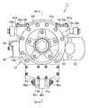
以下、本発明の実施の形態を図面に基づき詳細に説明する。まず、図1~図5を参照して、本発明の一実施形態に係るインホイールモータ駆動装置11の構成について説明する。なお、以下の説明においては、前方とは、車両の進行方向、すなわち図1の紙面表方向を示し、右方向とは、車輪の回転軸線方向の車体側、すなわち図1の紙面右方向を示し、上方向とは、鉛直上方、すなわち図1の紙面上方向を示すものとする。
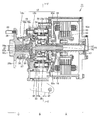
本発明の一実施形態に係るインホイールモータ駆動装置11は、駆動力を発生させるモータ部Aと、モータ部Aの回転を減速して出力する減速部Bと、減速部Bからの出力を車輪(図示せず)に伝える車輪ハブ26と、車輪ハブ26を回転可能に支持する車輪ハブ軸受部Cと、モータ部A、減速部B、および車輪ハブ軸受部Cの構成部材を覆うケーシング12とを備える。モータ部A、減速部B、および車輪ハブ軸受部Cは、直列かつ同軸に配置される。
モータ部Aは、外郭を形成するモータ部ケーシング12aと、モータ部ケーシング12aに固定されるステータ13と、ステータ13の内径側に隙間を空けて対向配置されるロータ14と、ロータ14の内径側に固定連結され、ロータ14と一体回転するモータ回転軸15とを有するラジアルギャップモータである。
モータ部ケーシング12aは、円筒状であり、その左側端において、径方向に広がる内向きフランジ状のフランジ部12eを含む。このフランジ部12eに、後述する減速部ケーシング12bの右側端が連結される。モータ部ケーシング12aの内周には、ステータ13が固定されている。なお、本実施形態においては、フランジ部12eが、モータ部ケーシング12aの一部として構成されている場合について述べたが、フランジ部12eが、モータ部ケーシング12aとは別部材として構成され、ボルト等により固定されていてもよい。
モータ部ケーシング12aを構成するフランジ部12eの内周は、軸受16を介してモータ回転軸15の左側端部を回転自在に支持する。モータ部ケーシング12aは、その右側端において、径方向に延在する円盤状のモータカバー12dを含む。モータカバー12dの中心部は、軸受17を介してモータ回転軸15の右側端部を回転自在に支持する。
減速部Bは、外郭を形成する減速部ケーシング12bと、減速機の出力軸としての車輪側回転部材18とを有し、モータ部Aの回転軸線方向左側に、同心状に配置される。本実施形態に係る減速部Bは、サイクロイド減速機によって構成されている。減速機の入力軸19は、回転軸線に沿って延びてモータ部A側へ突出し、その突出端が、モータ回転軸15の左側端部に嵌入固定される。モータ部Aのモータ回転軸15および減速部Bの入力軸19は、一体回転するものであって、モータ回転軸15および入力軸19によって、モータ側回転部材20が構成されている。入力軸19の左側端部は、減速部B内において軸受21によって支持される。
入力軸19の外周には、2枚の円盤形状の偏心部材22a,22bが固定される。モータ回転軸15および入力軸19は、モータ部Aの回転軸線と同心状に延在するが、偏心部材22a,22bの中心は、回転軸線と一致しない。さらに、2つの偏心部材22a,22bは、偏心運動による遠心力で発生するモーメントを互いに打ち消し合うために、180°位相を変えて設けられている。
偏心部材22a,22bの外周には、公転部材としての曲線板23a,23bがそれぞれ回転自在に保持される。外側輪郭線が波状の形状である曲線板23a,23bの外周部には、外周係合部材としての複数の外ピン24が係合する。外ピン24は、減速部ケーシング12bの内周に取り付けられる。曲線板23a,23bの隙間には、これら曲線板23a,23bの傾きを防止するセンターカラー56が設けられる。
減速部ケーシング12bは、モータ部ケーシング12aよりも小さな径の円筒形状を有しており、軸線方向右側端でモータ部ケーシング12aの左側端と結合し、軸線方向左側端で車輪ハブ軸受部Cを構成する外方部材12cの右側端と結合している。本実施形態に係るケーシング12は、モータ部ケーシング12a、減速部ケーシング12b、および外方部材12cによって構成されている。ケーシング12は、上記した軸受16、17や、後述する車輪ハブ軸受部Cを介して、ケーシング12内部の回転要素を回転自在に支持している。
減速部Bの出力部材である車輪側回転部材18は、回転軸線に沿って延在する軸部18bと、軸部18bの右側端部から外径方向に拡径するフランジ部18aとを有する。車輪側回転部材18の軸部18bは、減速部Bから軸線方向左側へ突出し、車輪ハブ軸受部Cまで延在する。減速部Bに配置されるフランジ部18aには、回転軸線を中心とする円周上の等間隔に複数の穴が形成されており、この穴に、内ピン25が嵌入固定されている。
車輪ハブ軸受部Cに配置される軸部18bの外周面には、車輪ハブ26が連結固定されており、車輪側回転部材18および車輪ハブ26は、一体回転する。フランジ部18aに固設された内ピン25は、フランジ部18aから軸線方向右側へ向かって突出し、その先端部が、曲線板23a,23bにそれぞれ設けられた後述する貫通孔27に受け入れられている。フランジ部18aの内部に画定された中心穴18cは、入力軸19の左側端部を受け入れるとともに、軸受21を介して入力軸19を相対回転自在に支持している。
曲線板23aは、外周部にエピトロコイド等のトロコイド系曲線で構成される複数の波形を有し、一方側端面から他方側端面に貫通する複数の貫通孔27,28を有する。貫通孔27は、曲線板23aの中心(自転軸心)を基準とした円周上に等間隔に複数個設けられており、曲線板23aの外周縁と内周縁との間の径方向中央領域に形成されて、上記した内ピン25を受け入れる。また、貫通孔28は、曲線板23aの中心(自転軸心)に設けられており、曲線板23aの内周面を画定している。上記したように、曲線板23aは、偏心部材22aの外周に相対回転可能に取り付けられる。
具体的には、曲線板23aは、軸受29を介して、偏心部材22aに回転自在に支持されている。この軸受29は、内周面が偏心部材22aの外周面に嵌合し、外周面に内側軌道面30aを有する内輪30と、貫通孔28の円周面に直接形成された外側軌道面28aと、内側軌道面30aおよび外側軌道面28aの間に配置される複数の円筒ころ31と、周方向に隣り合う円筒ころ31の間隔を保持する保持器(図示せず)とを有する円筒ころ軸受である。なお、円筒ころ軸受に限らず、深溝玉軸受を適用してもよい。内輪30は、円筒ころ31が転走する内側軌道面30aを軸線方向に挟んで向かい合う一対の鍔部をさらに有し、円筒ころ31を一対の鍔部間に保持している。
なお、曲線板23bの構成も、曲線板23aと同様であるため、詳細な説明を省略する。
外ピン24は、入力軸19の回転軸線を中心とする円周軌道上に等間隔に設けられる。外ピン24は、軸線と平行に延び、その両端が、ケーシング12のうち減速部Bを収容する減速部ケーシング12bの内壁面に嵌合固定されている外ピン保持部32に保持されている。より具体的には、外ピン24の軸線方向両端部が、外ピン保持部32に取り付けられた針状ころ軸受33によって回転自在に支持されている。
曲線板23a,23bが入力軸19の回転軸線を中心に公転運動すると、曲線形状の波形外周部と外ピン24とが係合して、曲線板23a,23bに自転運動を生じさせる。また外ピン24の両端に設けられた針状ころ軸受33により、外ピン24が曲線板23a,23bの外周面に当接する際、曲線板23a,23bとの摩擦抵抗が低減される。
本実施形態に係る減速部Bは、曲線板23a,23bの自転運動を、回転軸心を中心とする回転運動に変換して車輪側回転部材18に伝達する運動変換機構を有する。この運動変換機構は、車輪側回転部材18のフランジ部18aに固設された内ピン25と、曲線板23a,23bに設けられた貫通孔27とによって構成されている。内ピン25の外周には、中空円筒体および針状ころからなる針状ころ軸受34が設けられている。針状ころ軸受34により、内ピン25が曲線板23a,23bの貫通孔27の内周面に当接する際に、曲線板23a,23bとの摩擦抵抗が低減される。
内ピン25の右側端には、内ピン25を補強するための内ピン補強部材35が、圧入により連結固定されている。内ピン補強部材35は、曲線板23a,23bから内ピン25に負荷された荷重を、全ての内ピン25に均一に分散する機能を有する部材である。
貫通孔27は、複数の内ピン25を内部に受け入れるものであって、各内ピン25の位置に対応するように配設されている。また、貫通孔27の内径寸法は、内ピン25の外径寸法(針状ころ軸受34を含む最大外径を指す。以下同じ。)より所定分大きく設定されている。したがって、曲線板23a,23bに設けられた貫通孔27を貫通して延びる内ピン25は、貫通孔27の内周面と係合する内側係合部材となる。
車輪ハブ26は、回転軸線方向に沿って延在し、車輪側回転部材18の左側端と結合する円筒状の中空部26aと、中空部26aの右側端から外径方向に拡径するフランジ部26bとを有する。フランジ部26bには、ハブボルト39によって車輪のロードホイール(図示せず)が固定連結される。
車輪ハブ軸受部Cは、減速部Bの軸線方向左側に同心状に配置されており、車輪ハブ26を回転可能に支持している。車輪ハブ軸受部Cは、当該車輪ハブ軸受部Cの外郭を形成する外方部材12cと、車輪ハブ26の右側端外周に嵌設された内輪36と、外方部材12cと車輪ハブ26および内輪36との間に配置された複数の転動体37と、転動体37を所定の間隔に保持するための保持器38とを有する。
本実施形態に係る車輪ハブ軸受部Cは、複列アンギュラ玉軸受であって、その内側軌道面は、車輪ハブ26および内輪36の外周面に形成され、その外側軌道面は、ケーシング12を構成する外方部材12cの内周面に形成されている。
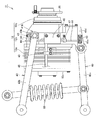
本実施形態に係るインホイールモータ駆動装置11は、一端がケーシング12に連結され、他端が車体を支持するサスペンション60に機械的に連結されるサスペンションアーム40を備える。具体的には、サスペンションアーム40は、一端が減速部ケーシング12bの上方領域の前後両側部に連結され、他端側にて車体側部材と機械的に連結される一対のアッパーアーム40a,40bと、一端が減速部ケーシング12bの下端部に連結され、他端がサスペンション60に機械的に連結されるロアアーム40cとを有する。
以下、サスペンションアーム40の取り付け構造について、詳述する。減速部ケーシング12bの前方上方部には、当該減速部ケーシング12bの外面から前方へと突出するように、アッパーアーム取り付け部41aが設けられている。同様にして、減速部ケーシング12bの後方上方部には、当該減速部ケーシング12bの外面から後方へと突出するように、アッパーアーム取り付け部41bが設けられている。また、減速部ケーシング12bの下端には、右下方へ向けて突出するロアアーム取り付け部41cが設けられている。なお、本実施形態においては、ロアアーム取り付け部41cは、前後方向に互いに離隔した一対の部材として構成されている。
前方側のアッパーアーム40aは、アッパーアーム取り付け部41aの前端部に回転可能に嵌入されている。同様に、後方側のアッパーアーム40bは、アッパーアーム取り付け部41bの後端部に回転可能に嵌入されている。ロアアーム40cは、一対のロアアーム取り付け部41cの間に架設された軸部42を介して、ロアアーム取り付け部41cに回転可能に連結されている。
ここで、本実施形態に係るインホイールモータ駆動装置11においては、ケーシング12に生じる歪みを検出するために、複数のセンサ43が、ケーシング12に取り付けられている。さらに具体的に説明すると、アッパーアーム取り付け部41aの上面45a、アッパーアーム取り付け部41bの上面45b、前方側ロアアーム取り付け部41cの前面45c、および、後方側ロアアーム取り付け部41cの後面45dに、計4個のセンサ43が、それぞれ取り付けられている。
本実施形態に係るセンサ43は、歪みを検出するセンサ素子と、当該センサ素子を外方から覆うカバーとを含む。この構成により、雨水や石の飛び跳ね等によるセンサの故障を防止することができる。
各センサ43には電気ケーブル44が接続されており、これら電気ケーブル44は、減速部ケーシング12bの外面に沿って配線され、減速部ケーシング12bの後端部中央に設置された信号処理装置46に接続されている。これにより、各センサ43と信号処理装置46とは電気的に接続され、各センサ43によって検出されたケーシング12の歪み信号が、信号処理装置46へと送信され、信号処理装置46において後述する信号処理が実行される。
なお、本実施形態においては、センサ43から延出した電気ケーブル44は、減速部ケーシング12bの外面に強固に巻き付けられ、且つ、減速部ケーシング12bに設けられたケーブル係止部材47によって係止されている。電気ケーブル44をこのように配線することによって、インホイールモータ駆動装置11の駆動中に電気ケーブル44が振動することを防止することができる。これにより、電気ケーブル44内を伝達する電気信号に、振動によるノイズが混入することを防ぐことができるとともに、電気ケーブル44の耐久性を向上させることも可能となる。
信号処理装置46からは、電気ケーブル48が延びており、電気ケーブル48は、車体側に設置された制御装置(図示せず)に接続される。これにより、信号処理装置46と制御装置とが電気的に接続され、制御装置は、信号処理装置46によって出力された演算結果に基づいて、インホイールモータ駆動装置全体を制御する。この構成については、後述する。
なお、信号処理装置46から延出する電気ケーブル48は、モータ部ケーシング12aに設けられたケーブル係止部材49によって係止されている。これにより、上記電気ケーブル44と同様に、振動によるノイズの混入を防ぐことができるとともに、電気ケーブル48の耐久性を向上させることができる。
減速部ケーシング12bの前端部中央には、当該減速部ケーシング12bの外面から前方へ突出するように、ブレーキキャリパ50が連結されている。このブレーキキャリパ50は、後述するブレーキを支持する部材である。ブレーキによって、車輪ハブ26に固定された車輪に対して、機械的な制動が与えられる。なお、図1では、ブレーキキャリパ50を破線で示している。
次に、図1~図5を参照して、本実施形態に係るインホイールモータ駆動装置11の回転系の動作原理について説明する。
モータ部Aは、例えば、ステータ13のコイルに交流電流を供給することによって生じる電磁力を受けて、永久磁石または磁性体によって構成されるロータ14が回転する。これにより、ロータ14に接続されたモータ回転軸15は回転を出力し、モータ回転軸15および入力軸19が回転する。そうすると、入力軸19に設けられた偏心部材22a,22bを介して、曲線板23a,23bが、入力軸19の回転軸線を中心として公転運動する。このとき、外ピン24が、曲線板23a,23bの曲線形状の波形外周部と転がり接触するように係合し、曲線板23a,23bを入力軸19の回転とは逆向きに自転運動させる。
貫通孔27に挿通された内ピン25は、貫通孔27の内径よりも小さな径を有しており、曲線板23a,23bの自転運動に伴って貫通孔27の孔壁面と当接する。これにより、曲線板23a,23bの公転運動が内ピン25に伝わることなく、曲線板23a,23bの自転運動のみが、車輪側回転部材18を介して車輪ハブ26に伝達されることとなる。このように、本実施形態においては、車輪側回転部材18に設けられた内ピン25と、内ピン25を受け入れる貫通孔27とが、曲線板23a,23bの自転運動を回転軸心周りの回転運動に変換して車輪側回転部材18に伝達する運動変換機構としての機能を果たす。
この運動変換機構を介して、車輪側回転部材18は、曲線板26a,26bの自転を減速部Bの出力として取り出す。この結果、モータ側回転部材20の回転が、減速部Bによって減速され、車輪側回転部材18に伝達される。
次に、図1~図8を参照して、本実施形態に係るインホイールモータ駆動装置11の制御系の動作について説明する。
図6に示すように、インホイールモータ駆動装置11を駆動させ、車両51が走行している場合においては、車輪52と路面53との接地状態に応じて、車輪52に様々な方向の荷重が作用することとなる。このように車輪52に負荷された荷重は、インホイールモータ駆動装置11に伝達し、ケーシング12に微小な歪みを生じさせる。
ここで、車体51の進行方向に沿う方向を方向x、車輪52の回転軸線方向を方向y、鉛直方向を方向zとすると、車輪52と路面53との接地状態に起因する車輪52への負荷荷重は、ケーシング12に生じた歪みの方向xの成分と、方向yの成分と、方向zの成分を検出することによって、効果的に推定することが可能である。
一方、インホイールモータ駆動装置11のモータ部Aを駆動した場合、モータ部Aのロータ14と、ステータ13との間にトルクが発生するため、ケーシング12にモータ側回転部材20の回転方向と逆方向に向けて、反力によるトルクが負荷される。また、モータ部Aが回生状態となっている場合においても、ロータ14とステータ13との間にトルクが生じ、ケーシング12に反力によるトルクが負荷されることとなる。さらに、ブレーキキャリパ50に支持されたブレーキ54によって、車輪ハブ26に連結されたディスクブレーキに機械的な制動力を加えた場合、ブレーキキャリパ50を介して、ケーシング12に反力によるトルクが負荷されることとなる。このように車輪52に負荷されたトルクも、上記と同様にケーシング12に微小な歪みを生じさせる。
ここで、車輪52の回転方向を方向rとすると、モータ部Aまたはブレーキ54による制動力に起因する車輪52への負荷荷重は、ケーシング12に生じた歪みの方向rの成分を検出することによって、効果的に推定することが可能である。
ここで、本発明に係るインホイールモータ駆動装置11においては、ケーシング12の歪みを検出するために、当該ケーシング12に、複数のセンサ43が取り付けられている。この構成によれば、ケーシング12に生じた歪みの方向xの成分、方向yの成分、および方向zの成分に加えて、車輪52の回転方向rの成分も検出することが可能となる。これにより、車輪52に負荷される荷重を、より高精度に推定することが可能となっている。以下、これについて具体的に説明する。
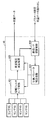
ケーシング12に設けられたセンサ43によって検出された歪みは、電気信号に変換され、電気ケーブル44を介して信号処理ユニット46へと入力される。なお、このセンサ43としては、抵抗歪みセンサ(ストレインゲージ)や圧電素子等といった、機械的変位を電気信号に変換可能な如何なる素子も適用可能である。
信号処理ユニット46は、前処理手段461と、荷重推定手段462と、パラメータ記憶手段463と、I/F機能を有する通信手段464とを有する。
前処理手段461は、各センサ43からの出力信号を増幅する増幅機能と、これらセンサ出力信号からノイズ成分を除去するフィルタリング機能と、増幅・フィルタリングされたセンサ出力信号をA/D変換するA/D変換機能を備える。これにより、センサ43からの微弱なセンサ出力信号が、センサ43の近傍に設置された信号処理装置46にてディジタル信号に変換されるので、ノイズの影響を受けにくくなり、検出精度を高めることができる。
センサ43からの出力信号には、センサ43自体の温度特性や、ケーシング12の温度特性、その他の原因によるドリフト量が存在する。そこで、荷重推定手段462において、センサ出力信号のドリフトを補正する必要がある。その補正のためのパラメータは、上記パラメータ記憶手段463に記憶される。このパラメータ記憶手段463は、例えば不揮発メモリによって構成される。また、温度によるドリフトを補正するために、例えば少なくとも一つのセンサ43の近傍に温度センサを設け、この温度センサの出力信号をセンサ43のセンサ出力信号とともに信号処理装置46に入力し、この情報をドリフト補正に使用しても良い。この場合において、温度センサに必要な情報も、パラメータ記憶手段463に記憶させておいても良い。この構成によれば、センサ43によって検出される歪み情報から、モータ部Aや減速部Bから発生する熱の影響を排除することができる。これにより、車輪52への負荷荷重をより高精度に演算することが可能となる。
荷重推定手段462は、ディジタル信号に変換されたセンサ出力信号と、パラメータ記憶手段463に記憶された各種演算用パラメータとに基づいて、車輪52に負荷された荷重を演算する。このように、センサ43の出力信号の演算を、全て信号処理装置46にて実行する構成としていることによって、システムをより簡易な構成とすることができ、且つ、外部配線の本数も最小化され、信頼性を向上させることができる。なお、荷重演算に用いられる補正係数も、パラメータ記憶手段463に記憶され、このパラメータ記憶手段463から読み出して使用される。演算用パラメータや補正係数は、予め試験やシミュレーションで求めておいて設定される。
ここで、本実施形態においては、上記したように、ケーシング12に設けられた複数のセンサ43によって、ケーシング12に生じた歪みの方向xの成分と、方向yの成分と、方向zの成分とを検出することができるため、荷重推定手段462は、車輪52に負荷される荷重の方向xの成分と、方向yの成分と、方向zの成分とを効果的に演算することができる。また、ケーシング12に設けられた複数のセンサ43によって、ケーシング12に生じた歪みの回転方向rの成分を検出することができるようになっている。したがって、荷重推定手段462は、回転方向rへの歪み情報に基づいて、車輪52に対して負荷される荷重のうち、回転方向rへの負荷荷重を、効果的に演算することが可能となっている。
荷重推定手段462により演算された荷重データは、通信手段464から、電気ケーブル48を介して、車体側に設置される制御装置55へと送信される。なお、電気ケーブル48としては、例えばCANバスを適用可能である。この構成によれば、信号処理装置46から制御装置55に荷重データを送信するのみならず、パラメータ記憶手段463に記憶される各種演算用パラメータを、このCANバスを介して、車体側の制御装置55から設定することも可能となる。
制御装置55は、荷重推定手段462により演算された荷重データに基づいて、車輪52と路面53との接地状態に関する情報と、ブレーキ54によって車輪52に対してもたらされる機械制動力に係る情報とを得ることができる。
具体的には、車輪52に負荷される荷重の方向xの成分と、方向yの成分と、方向zの成分とに基づいて、車輪52と路面53との接地状態に関する情報を得ることができる。
また、荷重推定手段462により演算された回転方向rへの負荷荷重は、モータ部Aによる回生制動力と、ブレーキ54による機械制動力との合成力によってもたらされるものである。一方、モータ部Aに与えているトルク指令値やモータ電流指令値を参照すれば、モータ部Aの回生制動力を推定することができる。したがって、制御装置55は、回転方向rへの負荷荷重値から、モータ部Aの回生制動力を引き算することによって、ブレーキ54による機械制動力を算出することができる。
制御装置55の出力側には、モータ部A、ブレーキ54、およびサスペンション60の減衰手段が接続されている。制御装置55は、上記のようにして得られた車輪52と路面53との接地状態に関する情報を、モータ部Aの制御や、車両の姿勢制御に利用する。これにより、安全性や経済性を、より向上させることができる。例えば、車両51の旋回が円滑に行われるように、上記情報をモータ部Aに出力し、左右の車輪52の回転速度を制御することができる。また、この制動時に、車輪52のロックが生じないように、ブレーキ54に上記情報を出力し、制動を制御することができる。また、旋回時に車体が左右に大きく傾いたり、加速時や制動時に車体が前後に大きく傾いたりするのを防止するために、サスペンション60の減衰手段に上記情報を出力し、サスペンション制御を行うことができる。また、本実施形態に係る制御装置は、ブレーキ54によって車輪52に対してもたらされる機械制動力に係る情報に基づいて、モータ部Aの回生と、ブレーキ54との協調制御を、最適に実行することができる。
このように、本実施形態によれば、車輪52と路面53との接地状態に応じて、車両51の旋回や姿勢、およびブレーキロック等を有利に制御することができる。また、ブレーキ54による機械制動力を算出することによって、モータ部Aの回生によって生じる回生制動力とのバランスを考慮しつつ、ブレーキ力を協調制御することができる。これにより、インホイールモータ駆動装置のより高度な制御を実現することができる。
また、本実施形態によれば、センサ43が、車輪ハブ軸受Cの転動体37から離隔しているため、転動体37の公転によってもたらされるノイズ成分を低減することが可能となる。これにより、演算処理を単純化することができるとともに、フィルタリング処理による時間遅れも低減することができる。すなわち、より簡易なアルゴリズムによって、車輪52への負荷荷重を、より高精度に演算することが可能となる。
また、本実施形態によれば、センサ43が、ケーシング12とサスペンションアーム40との連結部の近傍に取り付けられる。この構成によれば、歪みがより顕著に表れる上記連結部にセンサ43を取り付けることによって、ケーシング12に生じる歪みをより効果的に検出することができる。
なお、センサ43として、単体として複数の方向の荷重を検出可能な素子を適用してもよい。この構成によれば、適用するセンサの数を減らすことができるため、製造コストを低減することができる。
また、本実施形態においては、センサを減速部ケーシングに取り付けた場合について述べたが、これに限らず、ケーシングの如何なる位置に、如何なる数だけ取り付けてもよい。
また、本実施形態においては、センサを減速部ケーシングの外面に取り付けた場合について述べたが、これに限らず、ケーシングの内面側に取り付けられてもよい。この構成によれば、雨水や石の飛び跳ね等からセンサを保護することができるため、これらの要因によってセンサが故障することを防止することができる。
また、本実施形態においては、信号処理装置がケーシングに設けられている場合について述べたが、これに限らず、信号処理装置を車体側に配設する構成であってもよい。
以上、図面を参照して本発明の実施の形態を説明したが、本発明は、図示した実施の形態のものに限定されない。図示した実施の形態に対して、本発明と同一の範囲内において、あるいは均等の範囲内において、種々の修正や変形を加えることが可能である。
本発明は、より簡易な構成で高度な制御を実現可能なインホイールモータ駆動装置を提供するものであって、例えば自動車産業等の車両製造分野において有利に利用される。
11 インホイールモータ駆動装置、12 ケーシング、12a モータ部ケーシング、12b 減速部ケーシング、12c 外方部材、12e,18a,26b フランジ部、18b,42 軸部、12d モータカバー、13 ステータ、14 ロータ、15 モータ回転軸、16,17,21,29,33,34 軸受、18 車輪側回転部材、19 入力軸、20 モータ側回転部材、22a,22b 偏心部材、23a,23b 曲線板、24 外ピン、25 内ピン、26 車輪ハブ、26a 中空部、27,28 貫通孔、30,36 内輪、28a,30a 軌道面、31 ころ、32 外ピン保持部、35 内ピン補強部材、37 転動体、38 保持器、39 ハブボルト、40a,40b アッパーアーム、40c ロアアーム、41a,41b アッパーアーム取り付け部、41c ロアアーム取り付け部、43 センサ、44,48 電気ケーブル、45a,45b,45c,45d 面、46 信号処理装置、461 前処理手段、462 荷重推定手段、463 パラメータ記憶手段、464 通信手段、47,49 ケーブル係止部材、50 ブレーキキャリパ、51 車両、52 車輪、53 路面、54 ブレーキ、55 制御装置、60 サスペンション、56 センターカラー。
Claims (11)
- モータ側回転部材を回転駆動するモータ部と、
前記モータ側回転部材の回転を減速して車輪側回転部材に伝達する減速部と、
前記車輪側回転部材に固定連結された車輪ハブと、
前記車輪ハブを回転可能に支持する車輪ハブ軸受と、
前記モータ部、前記減速部、または前記車輪ハブ軸受を覆うケーシングと、
前記ケーシングに取り付けられ、当該ケーシングに生じる歪みを検出可能な複数のセンサと、
前記センサにより出力された歪み信号に基づいて、車輪に負荷される荷重を演算する信号処理装置と、を備える、インホイールモータ駆動装置。 - 前記センサは、前記ケーシングの内側に取り付けられる、請求項1に記載のインホイールモータ駆動装置。
- 前記センサは、前記ケーシングの外側に取り付けられ、カバーによって外方から覆われる、請求項1に記載のインホイールモータ駆動装置。
- 一端が前記ケーシングに連結され、他端が車体を支持するサスペンションに連結されるサスペンションアームをさらに備え、
前記センサは、前記ケーシングと前記サスペンションアームとの連結部の近傍に取り付けられる、請求項1~3のいずれかに記載のインホイールモータ駆動装置。 - 前記センサは、単体として複数の方向の歪みを検出可能である、請求項1~4のいずれかに記載のインホイールモータ駆動装置。
- 前記センサから延びる電気ケーブルは、前記ケーシングに設けられたケーブル係止部材によって係止される、請求項1~5のいずれかに記載のインホイールモータ駆動装置。
- 前記信号処理装置は、前記センサの出力信号に基づいて、前記車輪に負荷される少なくとも3方向の荷重と、前記車輪の回転方向rに生じる回転トルクとを演算可能であって、
前記3方向は、車両の進行方向に沿う方向x、前記車輪の回転軸方向y、および鉛直方向zである、請求項1~6のいずれかに記載のインホイールモータ駆動装置。 - 前記信号処理装置は、前記方向xの周りに生じる回転トルクと、前記鉛直方向zの周りに生じる回転トルクとをさらに演算可能である、請求項7に記載のインホイールモータ駆動装置。
- 前記信号処理装置は、
CANバスを介して車体側に設けられた制御装置へと接続され、
車輪に負荷される荷重を演算するために必要となる演算用パラメータを制御ユニット側から設定可能とするためのI/F手段をさらに有する、請求項1~8のいずれかに記載のインホイールモータ駆動装置。 - 車体側に設けられ、前記インホイールモータ駆動装置の駆動を制御する制御装置をさらに備え、
前記制御装置は、前記信号処理装置によって演算された前記車輪の回転方向rに生じる回転トルクと、前記モータ部が発生する回生トルクとを比較することによって、機械式ブレーキが発生させる機械制動力と、回生状態となった前記モータ部が発生させる回生制動力との比率を演算する、請求項1~9のいずれかに記載のインホイールモータ駆動装置。 - 前記制御装置は、前記機械制動力と前記回生制動力との比率に基づいて、前記インホイールモータ駆動装置の駆動を制御する、請求項10に記載のインホイールモータ駆動装置。
Priority Applications (3)
| Application Number | Priority Date | Filing Date | Title |
|---|---|---|---|
| US14/354,327 US9126476B2 (en) | 2011-10-28 | 2012-10-24 | In-wheel motor drive assembly |
| CN201280053037.XA CN103906643B (zh) | 2011-10-28 | 2012-10-24 | 轮内电动机驱动装置 |
| EP12843862.9A EP2772377B1 (en) | 2011-10-28 | 2012-10-24 | In-wheel motor drive device |
Applications Claiming Priority (2)
| Application Number | Priority Date | Filing Date | Title |
|---|---|---|---|
| JP2011-237260 | 2011-10-28 | ||
| JP2011237260A JP5809927B2 (ja) | 2011-10-28 | 2011-10-28 | インホイールモータ駆動装置 |
Publications (1)
| Publication Number | Publication Date |
|---|---|
| WO2013062005A1 true WO2013062005A1 (ja) | 2013-05-02 |
Family
ID=48167832
Family Applications (1)
| Application Number | Title | Priority Date | Filing Date |
|---|---|---|---|
| PCT/JP2012/077477 Ceased WO2013062005A1 (ja) | 2011-10-28 | 2012-10-24 | インホイールモータ駆動装置 |
Country Status (5)
| Country | Link |
|---|---|
| US (1) | US9126476B2 (ja) |
| EP (1) | EP2772377B1 (ja) |
| JP (1) | JP5809927B2 (ja) |
| CN (1) | CN103906643B (ja) |
| WO (1) | WO2013062005A1 (ja) |
Cited By (1)
| Publication number | Priority date | Publication date | Assignee | Title |
|---|---|---|---|---|
| WO2015046135A1 (ja) * | 2013-09-24 | 2015-04-02 | Ntn株式会社 | インホイールモータ駆動装置 |
Families Citing this family (19)
| Publication number | Priority date | Publication date | Assignee | Title |
|---|---|---|---|---|
| US9561715B2 (en) * | 2012-11-16 | 2017-02-07 | Deere & Company | Wheel hub with electric motor |
| US9914348B2 (en) * | 2014-06-30 | 2018-03-13 | Nissan North America, Inc. | Electric drive motor assembly for a wheel |
| JP6670571B2 (ja) * | 2015-09-28 | 2020-03-25 | Ntn株式会社 | インホイールモータ駆動装置とストラット式サスペンション装置の連結構造 |
| DE102015226589A1 (de) * | 2015-12-22 | 2017-06-22 | Zf Friedrichshafen Ag | Radaufhängungsanordnung |
| JP6334590B2 (ja) * | 2016-04-06 | 2018-05-30 | Ntn株式会社 | インホイールモータ駆動装置 |
| EP3444497B1 (en) * | 2016-04-15 | 2021-03-03 | Minebea Mitsumi Inc. | Wheel module |
| JP6823418B2 (ja) * | 2016-09-30 | 2021-02-03 | Ntn株式会社 | インホイールモータ駆動装置 |
| JP6125083B1 (ja) * | 2016-10-17 | 2017-05-10 | Ntn株式会社 | インホイールモータ駆動装置 |
| DE102017205473A1 (de) * | 2017-03-31 | 2018-10-04 | Robert Bosch Gmbh | Verfahren zum Betreiben eines Kraftfahrzeugs, Steuergerät und Kraftfahrzeug |
| SE541794C2 (en) * | 2017-05-31 | 2019-12-17 | Bae Systems Haegglunds Ab | Tracked vehicle having motor coaxially arranged with drive wheel |
| JP6539321B2 (ja) | 2017-09-25 | 2019-07-03 | 株式会社Subaru | 車両の制御システム及び車両の制御方法 |
| CN108556580A (zh) * | 2018-02-02 | 2018-09-21 | 福建(泉州)哈工大工程技术研究院 | 一种麦克纳姆轮全向移动平台独立悬架结构 |
| JP2020028136A (ja) * | 2018-08-09 | 2020-02-20 | Ntn株式会社 | 車両用モータ駆動装置 |
| JP7048460B2 (ja) * | 2018-09-10 | 2022-04-05 | Ntn株式会社 | インホイールモータ駆動装置 |
| US12179861B1 (en) | 2018-11-30 | 2024-12-31 | Robert P Thomas | Electric portal wheel hub system |
| US11697340B1 (en) * | 2018-11-30 | 2023-07-11 | Robert P Thomas | Electric portal wheel hub system |
| IT201900008883A1 (it) * | 2019-06-13 | 2020-12-13 | Freni Brembo Spa | Metodo e sistema per rilevare e misurare una forza di frenata di un sistema frenante per veicolo, mediante sensori fotonici incorporati in una pinza freno |
| JP7294747B2 (ja) * | 2020-07-28 | 2023-06-20 | 株式会社Soken | 回転状態検出装置 |
| FR3163908A1 (fr) * | 2024-06-26 | 2026-01-02 | Stellantis Auto Sas | Reducteur adaptable a de multiples configurations de vehicules electriques ou hybrides |
Citations (4)
| Publication number | Priority date | Publication date | Assignee | Title |
|---|---|---|---|---|
| JPH10271607A (ja) * | 1997-03-27 | 1998-10-09 | Mitsubishi Motors Corp | 電気自動車の制動制御装置 |
| JP2008081089A (ja) * | 2006-09-29 | 2008-04-10 | Ntn Corp | インホイール型モータ内蔵センサ付き車輪用軸受装置 |
| JP2008081090A (ja) * | 2006-09-29 | 2008-04-10 | Ntn Corp | インホイール型モータ内蔵センサ付き車輪用軸受装置 |
| JP2008126733A (ja) * | 2006-11-17 | 2008-06-05 | Ntn Corp | インホイール型モータ内蔵センサ付き車輪用軸受装置 |
Family Cites Families (8)
| Publication number | Priority date | Publication date | Assignee | Title |
|---|---|---|---|---|
| JP4193706B2 (ja) * | 2004-01-23 | 2008-12-10 | トヨタ自動車株式会社 | 路面摩擦係数検出装置 |
| US8167497B2 (en) * | 2005-08-08 | 2012-05-01 | Ntn Corporation | Sensor-equipped bearing for wheel |
| JP2007216932A (ja) * | 2006-02-20 | 2007-08-30 | Ntn Corp | インホイールモータ駆動装置 |
| JP5052084B2 (ja) * | 2006-09-19 | 2012-10-17 | Ntn株式会社 | インホイール型モータ内蔵センサ付きアクスルユニット |
| JP2008143490A (ja) * | 2006-11-13 | 2008-06-26 | Toyota Motor Corp | 車輪状態検出ユニットの検出対象車輪特定システムおよび検出対象車輪特定方法 |
| JP5409336B2 (ja) * | 2009-12-25 | 2014-02-05 | Ntn株式会社 | センサ付車輪用軸受 |
| JP5517869B2 (ja) * | 2009-11-27 | 2014-06-11 | Ntn株式会社 | インホイール型モータ内蔵センサ付き車輪用軸受装置 |
| JP5436191B2 (ja) * | 2009-12-21 | 2014-03-05 | Ntn株式会社 | インホイール型モータ内蔵センサ付き車輪用軸受装置 |
-
2011
- 2011-10-28 JP JP2011237260A patent/JP5809927B2/ja not_active Expired - Fee Related
-
2012
- 2012-10-24 WO PCT/JP2012/077477 patent/WO2013062005A1/ja not_active Ceased
- 2012-10-24 US US14/354,327 patent/US9126476B2/en not_active Expired - Fee Related
- 2012-10-24 EP EP12843862.9A patent/EP2772377B1/en not_active Not-in-force
- 2012-10-24 CN CN201280053037.XA patent/CN103906643B/zh not_active Expired - Fee Related
Patent Citations (4)
| Publication number | Priority date | Publication date | Assignee | Title |
|---|---|---|---|---|
| JPH10271607A (ja) * | 1997-03-27 | 1998-10-09 | Mitsubishi Motors Corp | 電気自動車の制動制御装置 |
| JP2008081089A (ja) * | 2006-09-29 | 2008-04-10 | Ntn Corp | インホイール型モータ内蔵センサ付き車輪用軸受装置 |
| JP2008081090A (ja) * | 2006-09-29 | 2008-04-10 | Ntn Corp | インホイール型モータ内蔵センサ付き車輪用軸受装置 |
| JP2008126733A (ja) * | 2006-11-17 | 2008-06-05 | Ntn Corp | インホイール型モータ内蔵センサ付き車輪用軸受装置 |
Cited By (2)
| Publication number | Priority date | Publication date | Assignee | Title |
|---|---|---|---|---|
| WO2015046135A1 (ja) * | 2013-09-24 | 2015-04-02 | Ntn株式会社 | インホイールモータ駆動装置 |
| JP2015065709A (ja) * | 2013-09-24 | 2015-04-09 | Ntn株式会社 | インホイールモータ駆動装置 |
Also Published As
| Publication number | Publication date |
|---|---|
| CN103906643A (zh) | 2014-07-02 |
| EP2772377A1 (en) | 2014-09-03 |
| US9126476B2 (en) | 2015-09-08 |
| EP2772377B1 (en) | 2018-10-03 |
| JP2013095183A (ja) | 2013-05-20 |
| JP5809927B2 (ja) | 2015-11-11 |
| CN103906643B (zh) | 2016-10-26 |
| EP2772377A4 (en) | 2015-11-11 |
| US20140300175A1 (en) | 2014-10-09 |
Similar Documents
| Publication | Publication Date | Title |
|---|---|---|
| JP5809927B2 (ja) | インホイールモータ駆動装置 | |
| JP5562277B2 (ja) | 電気自動車 | |
| JP5832868B2 (ja) | 電気自動車 | |
| JP5562276B2 (ja) | 電気自動車 | |
| JP6677258B2 (ja) | 車輪支持用転がり軸受ユニット | |
| WO2013077409A1 (ja) | 電動車両制御装置 | |
| WO2004099747A1 (ja) | センサ内蔵車輪用軸受 | |
| JP6681223B2 (ja) | インホイールモータ駆動装置 | |
| WO2018016236A1 (ja) | センシング装置付ホイール | |
| JP2003205833A (ja) | 車輪支持用転がり軸受ユニット | |
| WO2019053940A1 (ja) | シャシダイナモ装置用負荷モータ | |
| JP2015028430A (ja) | トルク検出装置 | |
| JP2010116017A (ja) | インホイールモータ駆動装置およびインホイールモータ駆動装置用ケーシング | |
| JP5851812B2 (ja) | 電動車両制御装置および電動車両 | |
| JP4507768B2 (ja) | 各輪独立駆動車両 | |
| JP6893843B2 (ja) | 車輪支持用転がり軸受ユニット | |
| JP6836974B2 (ja) | 車輪速検出装置およびインホイールモータ駆動装置 | |
| CN114830505A (zh) | 车辆用动力装置以及带有发电机的车轮用轴承装置 | |
| JP5985724B2 (ja) | 電気自動車 | |
| JP2017159877A (ja) | 駆動装置 | |
| WO2017038759A1 (ja) | 車両用モータ駆動装置およびこれを搭載した車両 | |
| JP5862180B2 (ja) | 車輪用軸受装置 | |
| JP2008081089A (ja) | インホイール型モータ内蔵センサ付き車輪用軸受装置 | |
| JP2018012356A (ja) | センシング装置付ホイール | |
| JP5856233B2 (ja) | 電気自動車 |
Legal Events
| Date | Code | Title | Description |
|---|---|---|---|
| 121 | Ep: the epo has been informed by wipo that ep was designated in this application |
Ref document number: 12843862 Country of ref document: EP Kind code of ref document: A1 |
|
| WWE | Wipo information: entry into national phase |
Ref document number: 2012843862 Country of ref document: EP |
|
| WWE | Wipo information: entry into national phase |
Ref document number: 14354327 Country of ref document: US |
|
| NENP | Non-entry into the national phase |
Ref country code: DE |