WO2013062126A1 - シート状複合体、その製造方法、この複合体を用いた電極及び電気化学素子 - Google Patents
シート状複合体、その製造方法、この複合体を用いた電極及び電気化学素子 Download PDFInfo
- Publication number
- WO2013062126A1 WO2013062126A1 PCT/JP2012/077866 JP2012077866W WO2013062126A1 WO 2013062126 A1 WO2013062126 A1 WO 2013062126A1 JP 2012077866 W JP2012077866 W JP 2012077866W WO 2013062126 A1 WO2013062126 A1 WO 2013062126A1
- Authority
- WO
- WIPO (PCT)
- Prior art keywords
- composite
- sheet
- carbon
- binder
- metal compound
- Prior art date
- Legal status (The legal status is an assumption and is not a legal conclusion. Google has not performed a legal analysis and makes no representation as to the accuracy of the status listed.)
- Ceased
Links
Images


Classifications
-
- H—ELECTRICITY
- H01—ELECTRIC ELEMENTS
- H01M—PROCESSES OR MEANS, e.g. BATTERIES, FOR THE DIRECT CONVERSION OF CHEMICAL ENERGY INTO ELECTRICAL ENERGY
- H01M4/00—Electrodes
- H01M4/02—Electrodes composed of, or comprising, active material
- H01M4/13—Electrodes for accumulators with non-aqueous electrolyte, e.g. for lithium-accumulators; Processes of manufacture thereof
- H01M4/131—Electrodes based on mixed oxides or hydroxides, or on mixtures of oxides or hydroxides, e.g. LiCoOx
-
- H—ELECTRICITY
- H01—ELECTRIC ELEMENTS
- H01G—CAPACITORS; CAPACITORS, RECTIFIERS, DETECTORS, SWITCHING DEVICES, LIGHT-SENSITIVE OR TEMPERATURE-SENSITIVE DEVICES OF THE ELECTROLYTIC TYPE
- H01G11/00—Hybrid capacitors, i.e. capacitors having different positive and negative electrodes; Electric double-layer [EDL] capacitors; Processes for the manufacture thereof or of parts thereof
- H01G11/22—Electrodes
- H01G11/30—Electrodes characterised by their material
- H01G11/50—Electrodes characterised by their material specially adapted for lithium-ion capacitors, e.g. for lithium-doping or for intercalation
-
- C—CHEMISTRY; METALLURGY
- C01—INORGANIC CHEMISTRY
- C01B—NON-METALLIC ELEMENTS; COMPOUNDS THEREOF; METALLOIDS OR COMPOUNDS THEREOF NOT COVERED BY SUBCLASS C01C
- C01B32/00—Carbon; Compounds thereof
- C01B32/05—Preparation or purification of carbon not covered by groups C01B32/15, C01B32/20, C01B32/25, C01B32/30
-
- C—CHEMISTRY; METALLURGY
- C01—INORGANIC CHEMISTRY
- C01G—COMPOUNDS CONTAINING METALS NOT COVERED BY SUBCLASSES C01D OR C01F
- C01G23/00—Compounds of titanium
- C01G23/003—Titanates
- C01G23/005—Alkali titanates
-
- H—ELECTRICITY
- H01—ELECTRIC ELEMENTS
- H01G—CAPACITORS; CAPACITORS, RECTIFIERS, DETECTORS, SWITCHING DEVICES, LIGHT-SENSITIVE OR TEMPERATURE-SENSITIVE DEVICES OF THE ELECTROLYTIC TYPE
- H01G11/00—Hybrid capacitors, i.e. capacitors having different positive and negative electrodes; Electric double-layer [EDL] capacitors; Processes for the manufacture thereof or of parts thereof
- H01G11/22—Electrodes
- H01G11/30—Electrodes characterised by their material
- H01G11/32—Carbon-based
- H01G11/36—Nanostructures, e.g. nanofibres, nanotubes or fullerenes
-
- H—ELECTRICITY
- H01—ELECTRIC ELEMENTS
- H01G—CAPACITORS; CAPACITORS, RECTIFIERS, DETECTORS, SWITCHING DEVICES, LIGHT-SENSITIVE OR TEMPERATURE-SENSITIVE DEVICES OF THE ELECTROLYTIC TYPE
- H01G11/00—Hybrid capacitors, i.e. capacitors having different positive and negative electrodes; Electric double-layer [EDL] capacitors; Processes for the manufacture thereof or of parts thereof
- H01G11/84—Processes for the manufacture of hybrid or EDL capacitors, or components thereof
- H01G11/86—Processes for the manufacture of hybrid or EDL capacitors, or components thereof specially adapted for electrodes
-
- H—ELECTRICITY
- H01—ELECTRIC ELEMENTS
- H01M—PROCESSES OR MEANS, e.g. BATTERIES, FOR THE DIRECT CONVERSION OF CHEMICAL ENERGY INTO ELECTRICAL ENERGY
- H01M4/00—Electrodes
- H01M4/02—Electrodes composed of, or comprising, active material
- H01M4/13—Electrodes for accumulators with non-aqueous electrolyte, e.g. for lithium-accumulators; Processes of manufacture thereof
- H01M4/139—Processes of manufacture
- H01M4/1391—Processes of manufacture of electrodes based on mixed oxides or hydroxides, or on mixtures of oxides or hydroxides, e.g. LiCoOx
-
- H—ELECTRICITY
- H01—ELECTRIC ELEMENTS
- H01M—PROCESSES OR MEANS, e.g. BATTERIES, FOR THE DIRECT CONVERSION OF CHEMICAL ENERGY INTO ELECTRICAL ENERGY
- H01M4/00—Electrodes
- H01M4/02—Electrodes composed of, or comprising, active material
- H01M4/13—Electrodes for accumulators with non-aqueous electrolyte, e.g. for lithium-accumulators; Processes of manufacture thereof
- H01M4/139—Processes of manufacture
- H01M4/1393—Processes of manufacture of electrodes based on carbonaceous material, e.g. graphite-intercalation compounds or CFx
-
- H—ELECTRICITY
- H01—ELECTRIC ELEMENTS
- H01M—PROCESSES OR MEANS, e.g. BATTERIES, FOR THE DIRECT CONVERSION OF CHEMICAL ENERGY INTO ELECTRICAL ENERGY
- H01M4/00—Electrodes
- H01M4/02—Electrodes composed of, or comprising, active material
- H01M4/13—Electrodes for accumulators with non-aqueous electrolyte, e.g. for lithium-accumulators; Processes of manufacture thereof
- H01M4/139—Processes of manufacture
- H01M4/1395—Processes of manufacture of electrodes based on metals, Si or alloys
-
- H—ELECTRICITY
- H01—ELECTRIC ELEMENTS
- H01M—PROCESSES OR MEANS, e.g. BATTERIES, FOR THE DIRECT CONVERSION OF CHEMICAL ENERGY INTO ELECTRICAL ENERGY
- H01M4/00—Electrodes
- H01M4/02—Electrodes composed of, or comprising, active material
- H01M4/36—Selection of substances as active materials, active masses, active liquids
- H01M4/362—Composites
- H01M4/364—Composites as mixtures
-
- H—ELECTRICITY
- H01—ELECTRIC ELEMENTS
- H01M—PROCESSES OR MEANS, e.g. BATTERIES, FOR THE DIRECT CONVERSION OF CHEMICAL ENERGY INTO ELECTRICAL ENERGY
- H01M4/00—Electrodes
- H01M4/02—Electrodes composed of, or comprising, active material
- H01M4/36—Selection of substances as active materials, active masses, active liquids
- H01M4/48—Selection of substances as active materials, active masses, active liquids of inorganic oxides or hydroxides
- H01M4/485—Selection of substances as active materials, active masses, active liquids of inorganic oxides or hydroxides of mixed oxides or hydroxides for inserting or intercalating light metals, e.g. LiTi2O4 or LiTi2OxFy
-
- H—ELECTRICITY
- H01—ELECTRIC ELEMENTS
- H01M—PROCESSES OR MEANS, e.g. BATTERIES, FOR THE DIRECT CONVERSION OF CHEMICAL ENERGY INTO ELECTRICAL ENERGY
- H01M4/00—Electrodes
- H01M4/02—Electrodes composed of, or comprising, active material
- H01M4/36—Selection of substances as active materials, active masses, active liquids
- H01M4/58—Selection of substances as active materials, active masses, active liquids of inorganic compounds other than oxides or hydroxides, e.g. sulfides, selenides, tellurides, halogenides or LiCoFy; of polyanionic structures, e.g. phosphates, silicates or borates
- H01M4/583—Carbonaceous material, e.g. graphite-intercalation compounds or CFx
- H01M4/587—Carbonaceous material, e.g. graphite-intercalation compounds or CFx for inserting or intercalating light metals
-
- H—ELECTRICITY
- H01—ELECTRIC ELEMENTS
- H01M—PROCESSES OR MEANS, e.g. BATTERIES, FOR THE DIRECT CONVERSION OF CHEMICAL ENERGY INTO ELECTRICAL ENERGY
- H01M4/00—Electrodes
- H01M4/02—Electrodes composed of, or comprising, active material
- H01M4/62—Selection of inactive substances as ingredients for active masses, e.g. binders, fillers
- H01M4/624—Electric conductive fillers
- H01M4/625—Carbon or graphite
-
- H—ELECTRICITY
- H01—ELECTRIC ELEMENTS
- H01M—PROCESSES OR MEANS, e.g. BATTERIES, FOR THE DIRECT CONVERSION OF CHEMICAL ENERGY INTO ELECTRICAL ENERGY
- H01M4/00—Electrodes
- H01M4/02—Electrodes composed of, or comprising, active material
- H01M4/62—Selection of inactive substances as ingredients for active masses, e.g. binders, fillers
- H01M4/624—Electric conductive fillers
- H01M4/626—Metals
-
- H—ELECTRICITY
- H01—ELECTRIC ELEMENTS
- H01M—PROCESSES OR MEANS, e.g. BATTERIES, FOR THE DIRECT CONVERSION OF CHEMICAL ENERGY INTO ELECTRICAL ENERGY
- H01M4/00—Electrodes
- H01M4/02—Electrodes composed of, or comprising, active material
- H01M4/04—Processes of manufacture in general
- H01M4/0471—Processes of manufacture in general involving thermal treatment, e.g. firing, sintering, backing particulate active material, thermal decomposition, pyrolysis
-
- H—ELECTRICITY
- H01—ELECTRIC ELEMENTS
- H01M—PROCESSES OR MEANS, e.g. BATTERIES, FOR THE DIRECT CONVERSION OF CHEMICAL ENERGY INTO ELECTRICAL ENERGY
- H01M4/00—Electrodes
- H01M4/02—Electrodes composed of, or comprising, active material
- H01M4/62—Selection of inactive substances as ingredients for active masses, e.g. binders, fillers
- H01M4/621—Binders
-
- Y—GENERAL TAGGING OF NEW TECHNOLOGICAL DEVELOPMENTS; GENERAL TAGGING OF CROSS-SECTIONAL TECHNOLOGIES SPANNING OVER SEVERAL SECTIONS OF THE IPC; TECHNICAL SUBJECTS COVERED BY FORMER USPC CROSS-REFERENCE ART COLLECTIONS [XRACs] AND DIGESTS
- Y02—TECHNOLOGIES OR APPLICATIONS FOR MITIGATION OR ADAPTATION AGAINST CLIMATE CHANGE
- Y02E—REDUCTION OF GREENHOUSE GAS [GHG] EMISSIONS, RELATED TO ENERGY GENERATION, TRANSMISSION OR DISTRIBUTION
- Y02E60/00—Enabling technologies; Technologies with a potential or indirect contribution to GHG emissions mitigation
- Y02E60/10—Energy storage using batteries
-
- Y—GENERAL TAGGING OF NEW TECHNOLOGICAL DEVELOPMENTS; GENERAL TAGGING OF CROSS-SECTIONAL TECHNOLOGIES SPANNING OVER SEVERAL SECTIONS OF THE IPC; TECHNICAL SUBJECTS COVERED BY FORMER USPC CROSS-REFERENCE ART COLLECTIONS [XRACs] AND DIGESTS
- Y02—TECHNOLOGIES OR APPLICATIONS FOR MITIGATION OR ADAPTATION AGAINST CLIMATE CHANGE
- Y02E—REDUCTION OF GREENHOUSE GAS [GHG] EMISSIONS, RELATED TO ENERGY GENERATION, TRANSMISSION OR DISTRIBUTION
- Y02E60/00—Enabling technologies; Technologies with a potential or indirect contribution to GHG emissions mitigation
- Y02E60/13—Energy storage using capacitors
Definitions
- the present invention relates to a sheet-like composite obtained by paper-making a composite material of an electrode active material and a carbon material with a fibrous carbon binder, a manufacturing method thereof, and an electrode and an electrochemical device using the sheet-like composite.
- lithium titanate whose oxidation-reduction potential is higher than the reduction potential of the electrolytic solution, has been studied.
- lithium titanate has a problem of low output characteristics.
- an organic binder such as polyvinylidene fluoride (hereinafter referred to as PVDF) has been used as a binder when forming the electrode.
- PVDF polyvinylidene fluoride
- the organic binder is an insulator, there is a problem that it causes a decrease in output characteristics and energy density, and there is an increasing expectation for an electrode that does not use the organic binder.
- the present invention has been proposed in order to solve the above-described problems of the prior art, and an object of the present invention is to provide a metal compound capable of inserting and extracting lithium into a carbon material without using an organic binder.
- a sheet-like composite capable of obtaining an electrode or an electrochemical element that achieves output characteristics and high energy density by paper-molding a supported composite material into a sheet form with a fibrous carbon binder, and a method for producing the same It is to provide.
- Another object of the present invention is to provide an electrode and an electrochemical device using the sheet composite.
- a sheet-like composite of the present invention is a carbon nanotube or carbon nanofiber having a specific surface area of less than 600 m ⁇ 2> / g made of a composite material in which a metal compound capable of occluding and releasing lithium is supported on a carbon material. Paper-molding is performed using a fibrous carbon binder containing any of carbon fibers.
- a sheet-like composite obtained by adding 7 wt% to 200 wt% of a fibrous carbon binder to the composite material is also an embodiment of the present invention.
- a sheet-like composite having a thickness of 20 to 60 ⁇ m is also an embodiment of the present invention.
- An electrode in which a sheet-like composite is formed on the surface of the current collector is also an embodiment of the present invention.
- An electrochemical element using the electrode is also an embodiment of the present invention.
- the method for producing a sheet-like composite of the present invention includes a composite treatment for obtaining a composite material by supporting a metal compound capable of occluding and releasing lithium in a carbon material, and stirring the composite material and the fibrous carbon binder. And a sheet forming process for obtaining a sheet-like composite by paper-molding the stirred mixed solution.
- the fibrous carbon binder has a specific surface area of 600 m 2 / g. Any one of carbon nanotubes, carbon nanofibers, and carbon fibers is included.
- the mixture obtained by applying shear stress and centrifugal force to the starting material of the metal compound capable of occluding and releasing lithium and the carbon material in the swirling reactor is heated, and lithium is added to the carbon material. It is also an embodiment of the present invention to obtain a composite material carrying a metal compound capable of being occluded and released.
- a sheet-shaped composite formed by adding a fibrous carbon binder that is not an organic substance to a composite material composed of a metal compound capable of occluding and releasing lithium and a carbon material has high rate characteristics, Shows output characteristics and high capacity characteristics.
- the electrode and electrochemical element using this sheet-like composite can also achieve the same effect.
- a sheet-like composite of a metal compound capable of occluding and releasing lithium according to the present embodiment (hereinafter referred to as metal compound) and a fibrous carbon binder (hereinafter referred to as fibrous carbon),
- metal compound a metal compound capable of occluding and releasing lithium according to the present embodiment
- fibrous carbon a fibrous carbon binder
- UC processing ultra-centrifugal force processing method
- a composite material of a metal compound and a carbon material is produced.
- fibrous carbon and a solvent are added to the composite material as a binder and stirred to prepare a mixed solution, and the mixed solution is made into a paper to form a sheet-like composite. Make it.
- the metal compound, the carbon material, and the fibrous carbon used in the present embodiment will be described, and the manufacturing steps (1) and (2) will be described in detail.
- the metal compound, carbon material, and fibrous carbon used in the present embodiment have the following characteristics.
- metals such as Si, Sn, and Ge that are M ⁇ M ′ ⁇
- lithium titanate (hereinafter referred to as LTO) can be used.
- LTO LTO produced
- titanium (IV) tetrabutoxy monomer Ti [O (CH 2 ) 3 CH 3 ] 4 , Wako Pure Chemical Industries, Ltd., first grade
- isopropyl alkoxide, titanium chloride and the like can be used.
- a titanium source solution is prepared by adding acetic acid (CH3COOH, manufactured by Kanto Chemical Co., Ltd., special grade) as a chelating reagent, and isopropyl alcohol ((CH 3 ) 2 CHOH, manufactured by Wako Pure Chemical Industries, Ltd., for organic synthesis) as a solvent.
- acetic acid CH3COOH, manufactured by Kanto Chemical Co., Ltd., special grade
- isopropyl alcohol ((CH 3 ) 2 CHOH, manufactured by Wako Pure Chemical Industries, Ltd., for organic synthesis)
- lithium acetate CH3COOLi, manufactured by Wako Pure Chemical Industries, Ltd., special grade
- the Li source solution is prepared by dissolving lithium acetate in a mixed solution of distilled water, acetic acid and isopropyl alcohol.
- Carbon materials used in the present embodiment include carbon nanotubes (hereinafter referred to as CNT) and carbon nanofibers (hereinafter referred to as CNF) having a fiber structure, and ketjen black that is a carbon black having a hollow shell-like structure.
- CNT carbon nanotubes
- CNF carbon nanofibers
- ketjen black that is a carbon black having a hollow shell-like structure.
- KB carbon black
- carbon black such as acetylene black, amorphous carbon, carbon fiber, natural graphite, artificial graphite, activated carbon, and mesoporous carbon.
- This carbon material becomes a composite material by mixing with the starting material of the metal compound and performing UC treatment.
- fibrous carbon binder As the fibrous carbon binder used in the present embodiment, carbon nanotubes having a fiber diameter of 1 to 10 nm (hereinafter referred to as CNT) are used. In addition to CNTs, carbon nanofibers with a fiber diameter of 10 to 1000 nm (hereinafter referred to as CNF) and carbon fibers with a fiber diameter exceeding 1 ⁇ m and approximately 10 ⁇ m and a maximum of 100 ⁇ m (hereinafter referred to as CF) are used as fibrous carbon. Can be used.
- the fibrous carbon acts as a binder when the composite material is mixed with the composite material to form a sheet by papermaking.
- the fibrous carbon used in the present embodiment has a specific surface area of less than 600 m 2 / g.
- the composite material used by this implementation processing is produced by adding the starting material of a metal compound to a carbon material, and compounding by UC processing. Further, when the carbon material has a fiber structure (for example, CNT, CNF), ultra high pressure dispersion treatment may be performed for the purpose of dispersion and homogenization of the fiber structure.
- a fiber structure for example, CNT, CNF
- the composite treatment of the composite material when the carbon material has a fiber structure
- A As an ultra-high pressure dispersion treatment, a carbon material having a fiber structure is dispersed
- B As a UC treatment, a starting material of a metal compound is added to a carbon material dispersed by an ultra-high pressure dispersion treatment, and a UC treatment, which is one of mechanochemical reactions
- C The product obtained through the treatments (a) and (b) is dried and then fired to produce a composite material of a metal compound and a carbon material.
- (A) Mixing process In the mixing process, a carbon material having a fiber structure and a solvent are mixed to form a mixed solution.
- a method for mixing the carbon material and the solvent an existing method can be used. An example is mixing with a homogenizer.
- the ratio of the carbon material to the solvent is preferably 0.5 to 1 g with respect to 1 L of the solvent.
- a homogenizer is a type of generator that consists of a drive unit, a fixed outer blade, and a rotating inner blade, and performs a series of homogenization of high-speed dispersion, pulverization, and homogenization. Thereby, the composite material and the fibrous carbon binder are uniformly dispersed in the solvent, and the fibrous carbon binder is pulverized.
- the solvent to be mixed with the carbon material having a fiber structure alcohols, water, and a mixed solvent thereof can be used.
- isopropyl alcohol can be used as a solvent.
- IPA is used as the solvent, an advantageous effect of suppressing aggregation of the carbon material having a fiber structure can be obtained.
- a known method generally called jet mixing is used. That is, a pair of nozzles are provided at positions facing each other on the inner wall of the cylindrical chamber, and a mixed solution of carbon material having a fiber structure pressurized by a high-pressure pump is sprayed from each nozzle to cause a frontal collision in the chamber. . Thereby, the bundle of carbon materials can be crushed and dispersed and homogenized.
- the carbon material is treated at a pressure and concentration of 200 MPa, 3 Pass, 0.5 g / L.
- the carbon material is added to a solvent such as IPA as a pretreatment instead of the treatments (a) and (b), and mixed to obtain a mixed solution. Is generated.
- a solvent such as IPA
- An existing method can be used as a method for mixing the mixed solution.
- An example is mixing with a homogenizer.
- the ratio of the carbon material to the solvent is preferably 0.5 to 1 g with respect to 1 L of the solvent.
- UC processing a metal alkoxide, a lithium compound, and a reaction inhibitor are added to the mixed solvent in which the carbon material that has undergone pretreatment is dispersed, and UC processing is performed.
- a metal alkoxide, a lithium compound, and a reaction inhibitor which are starting materials of a metal oxide active material that is a metal compound, are added to a carbon material that has undergone an ultra-high pressure dispersion process, and UC is one of the mechanochemical reactions. Process.
- the metal alkoxide, the lithium compound, and the reaction inhibitor will be described.
- Metal alkoxide As the metal alkoxide used in the present embodiment, a metal alkoxide capable of occluding and releasing lithium is used. As the metal alkoxide, titanium alkoxide is preferable, and those having a reaction rate constant of hydrolysis reaction of metal alkoxide of 10 ⁇ 5 mol ⁇ 1 sec ⁇ 1 or more are preferable.
- lithium compound As the lithium compound, lithium acetate (CH3COOLi, manufactured by Wako Pure Chemical Industries, Ltd., special grade) can be used. As a lithium source other than lithium acetate, lithium hydroxide, lithium carbonate, lithium nitrate, or the like can be used.
- the lithium compound solution can be prepared by dissolving lithium acetate in a mixed solution of distilled water, acetic acid and isopropyl alcohol.
- reaction inhibitor When titanium alkoxide was used as the metal alkoxide, the reaction was too fast and titanium oxide was formed when producing lithium titanate, and there was a problem that lithium titanate could not be produced. .
- Substances capable of forming a complex with titanium alkoxide include acetic acid, citric acid, succinic acid, formic acid, lactic acid, tartaric acid, fumaric acid, succinic acid, propionic acid, carboxylic acid such as propionic acid, and aminopolyester such as EDTA.
- Examples include complexing agents represented by amino alcohols such as carboxylic acid and triethanolamine.
- the UC process of this embodiment can be performed, for example using a reactor as shown in FIG.
- the reactor includes an outer cylinder 1 having a cough plate 1-2 at an opening and an inner cylinder 2 having a through hole 2-1 and swirling.
- the reactant inside the inner cylinder 2 passes through the through-hole 2-1 of the inner cylinder 2 by the centrifugal force.
- the reaction product collides with the inner wall 1-3 of the outer cylinder 1 by the centrifugal force of the inner cylinder 2, and forms a thin film and slides up to the upper part of the inner wall 1-3.
- the thickness of the thin film is 5 mm or less, preferably 2.5 mm or less, more preferably 1.0 mm or less.
- the thickness of the thin film can be set according to the width of the dam plate and the amount of the reaction solution.
- the reaction method of the present embodiment can be realized by the mechanical energy of shear stress and centrifugal force applied to the reactant, and this shear stress and centrifugal force are applied to the reactant in the inner cylinder.
- the centrifugal force applied to the reactants in the inner cylinder necessary for the present embodiment is 1500 N (kgms -2) or more, preferably 70000N (kgms -2) or more, more preferably 270000N (kgms -2) or .
- reaction method of the present embodiment described above is a liquid phase reaction, it can be applied to various reactions such as a hydrolysis reaction, an oxidation reaction, a polymerization reaction, and a condensation reaction.
- uniform metal compound nanoparticles can be formed by applying to the metal salt hydrolysis reaction and condensation reaction conventionally performed by the sol-gel method.
- the above metal compound nanoparticles act as active materials suitable for electrodes for electrochemical devices. That is, by making nanoparticles, the specific surface area is greatly expanded, and the output characteristics and capacity characteristics are improved.
- a carbon material in which metal compound nanoparticles are supported in a highly dispersed state can be obtained by adding a carbon material in the reaction process. It can. That is, the starting material of the metal compound and the carbon material are put into the inner cylinder of the reactor of FIG. 9, and the inner cylinder is swirled to mix and disperse the starting material of the metal compound and the carbon material. Further, while turning the inner cylinder, a catalyst such as sodium hydroxide is added to cause hydrolysis and condensation reaction to proceed to produce a metal compound, and the metal compound and the carbon material are mixed in a dispersed state. Upon completion of the reaction, it is possible to form a carbon material in which the precursor of the metal compound nanoparticles is supported in a highly dispersed manner.
- a catalyst such as sodium hydroxide
- the metal oxide active material nanoparticle precursor be supported in a highly dispersed manner on the carbon material by a two-step UC treatment. That is, as the first UC treatment, a carbon material, a metal alkoxide, and isopropyl alcohol are introduced into the inner cylinder of the reactor, and the inner cylinder is turned to obtain a mixed solution in which the carbon material and the metal alkoxide are uniformly dispersed. .
- the chemical reaction between the metal alkoxide and the lithium compound is promoted by introducing a mixed solution containing a lithium compound, a reaction inhibitor, and water while turning the inner cylinder.
- a carbon material carrying a highly dispersed metal compound precursor capable of occluding and releasing lithium is obtained.
- the metal alkoxide and the carbon material are dispersed before starting the chemical reaction with the metal compound capable of inserting and extracting lithium, so that the precursor of the metal compound capable of inserting and extracting lithium is uniformly a carbon material.
- the aggregation of the metal compound nanoparticles is prevented, and the output characteristics are improved.
- a carbon material in which a precursor of a metal compound capable of occluding and releasing lithium is dispersedly supported can be generated even by a one-step UC treatment.
- a carbon material, a metal alkoxide, a reaction inhibitor, and water are put into the inner cylinder of the reactor, and the inner cylinder is swirled to mix and disperse them and to proceed with hydrolysis and condensation reactions. , Promote chemical reactions.
- a carbon material in which a precursor of a metal compound capable of occluding and releasing lithium can be dispersed and supported upon completion of the reaction can be obtained.
- a mixed solution of the carbon material on which the metal compound precursor obtained by the UC treatment is highly dispersed and supported is dried in the range of 85 ° C. to 100 ° C. This prevents aggregation of the metal compound and improves the capacity and output characteristics of the electrode or electrochemical device using the electrode material of the present embodiment.
- Sheeting treatment of composite material a composite material of a metal compound and a carbon material that has undergone composite treatment of composite material and fibrous carbon that is a binder are added to a solvent and stirred. To produce a slurry-like mixed solution. Thereby, the composite material and the fibrous carbon are uniformly dispersed in the solvent, and the fibrous carbon is pulverized. This mixed solution is formed into paper and dried under reduced pressure to form a sheet.
- the fibrous carbon binder may be dispersed by an ultrahigh pressure dispersion treatment.
- B As a stirring process, a mixed solution obtained by adding a composite material to fibrous carbon dispersed by an ultra-high pressure dispersion process is stirred;
- C As a sheet forming process, the stirred mixed solution is formed into paper, and dried under reduced pressure to form a sheet, thereby producing a sheet-like composite.
- the pretreatment for dispersing the fibrous carbon binder by the ultrahigh pressure dispersion treatment is the same as (a) pretreatment in the composite treatment of the composite material described above.
- the fibrous carbon binder and IPA are mixed to produce a mixed solution, and this mixed solution is subjected to an ultrahigh pressure dispersion treatment to obtain a mixed solution in which the fibrous carbon binder is dispersed.
- a homogenizer can be used for stirring the mixed solution.
- a homogenizer is a kind of generator, and consists of a drive unit, a fixed outer blade, and a rotating inner blade, and performs a series of homogenization from high-speed dispersion to fine crushing to homogenization. Thereby, the composite material and the fibrous carbon binder are uniformly dispersed in the solvent, and the fibrous carbon binder is pulverized.
- (C) Sheeting process In the sheeting process, the mixed solution that has undergone the stirring process is formed into a sheet by paper making. In papermaking molding, the mixed solution is filtered under reduced pressure using PTFE filter paper (diameter: 35 mm, average pore 0.2 ⁇ m) to form a sheet. This sheet was dried under reduced pressure at 60 ° C. for 3 hours. Through the above treatment, a sheet-like composite of the composite material and fibrous carbon can be formed. The sheet-like composite is subjected to a rolling process such as pressing as necessary.
- Electrode A sheet-like composite of composite material and fibrous carbon is cut into the same size as a current collector of a metal foil such as an aluminum foil, placed on the current collector, and sandwiched between separately prepared metal foils from above, The current collector and the sheet-like composite are integrated by pressing from the vertical direction of the metal foil at a pressure of 10 t / cm 2 for 1 minute.
- the sheet-like composite integrated with the current collector can be used as an electrode of an electrochemical element, that is, an electric energy storage electrode, and the electrode exhibits high output characteristics and high capacity characteristics.
- the current collector a foil made of a metal material such as aluminum, copper, platinum or the like is used, and an etching foil or a flat plain foil that has been subjected to uneven processing by an etching process is used on the surface.
- the pressing pressure for integrating the current collector and the sheet-like composite is preferably 0.01 to 100 t / cm 2 , and the pressure is applied to the enlarged uneven portion of the etched aluminum foil by this pressing.
- this convex part bites into the sheet-like composite formed by papermaking, or a part of the sheet-like composite is sandwiched in the concave part, whereby excellent bondability can be imparted.
- Electrochemical elements that can use the sheet-like composite and the electrode using the sheet-like composite are electrochemical capacitors and batteries that use an electrolytic solution containing metal ions such as lithium and magnesium. That is, the electrode of the present embodiment can occlude and desorb metal ions, and operates as a negative electrode and a positive electrode. For example, by stacking the electrode of the present embodiment with an electrode such as activated carbon as a counter electrode, carbon or metal oxide that occludes and desorbs metal ions, a separator, and using an electrolytic solution containing metal ions, Electrochemical capacitors and batteries can be configured.
- an electrode such as activated carbon as a counter electrode, carbon or metal oxide that occludes and desorbs metal ions, a separator, and using an electrolytic solution containing metal ions.
- Example 1 and Comparative Example 1 used in the first characteristic comparison are as follows. In this characteristic comparison, LTO is used as a metal compound, CNF is used as a carbon material, and CNT is used as fibrous carbon added as a binder to the composite material.
- Example 1 In Example 1, a mixed solution in which CNF is dispersed in IPA by jet mixing is generated, and the mixed solution, titanium alkoxide, and IPA are introduced into the inner cylinder of a reactor that performs UC treatment. Then, a lithium compound, a reaction inhibitor and water were added, and a second UC treatment was performed to obtain CNF carrying a highly dispersed LTO precursor. The CNF carrying the LTO precursor in a highly dispersed state was dried at 90 ° C. and further fired at 900 ° C. in a nitrogen atmosphere to obtain a composite material in which lithium titanate nanoparticles were highly dispersed and supported on the CNF.
- a mixed solution in which the CNT binder is dispersed in IPA by jet mixing is generated, and the composite material is added to the mixed solution and stirred to prepare a slurry-like mixed solvent.
- PTFE filter paper (diameter: 35 mm) Then, filtration under reduced pressure was performed using an average pore size of 0.2 ⁇ m, and a paper sheet was formed to obtain a sheet, and then the sheet was dried under reduced pressure at 60 ° C. for 3 hours to form a sheet composite.
- Example 1 formed a paper composite using a CNT binder to form a sheet-like composite, whereas the binder was not used during papermaking, and the others were the same as Example 1. did.
- FIG. 1A is a photograph showing the state of the sheet-like composite of Example 1
- FIG. 1B is an SEM image of the back side of the sheet-like composite of Example 1. From FIG. 1A, it can be seen that in Example 1 in which CNT is added as a binder, the fibrous CNT acts as a binder on the particulate composite material to form a self-supporting sheet. Further, from FIG. 1 (b), it can be seen that the particles of the composite material are not exposed on the surface of the sheet-like composite by uniformly disposing the particulate composite material on the self-supporting sheet.
- FIG. 2 is a view showing a state of the sheet-like composite of Comparative Example 1. From FIG. 2, in the comparative example 1 which did not use a fibrous carbon binder, the composite material of particulate LTO and CNF is only deposited. It can be seen that the composite material itself of LTO and CNF is not integrated and does not form a sheet because there is no action such as adhesion, adhesion, and bonding.
- the fibrous CNT binder is entangled and the LTO is in the form of nano-level particles.
- a carbon material (composite material) carrying s is taken in.
- the sheet-like composite and the sheet-like composite in which the composite material of the metal compound and the carbon material is uniformly arranged As described above, by adding fibrous carbon as a binder to the composite material of the metal compound and the carbon material, the sheet-like composite and the sheet-like composite in which the composite material of the metal compound and the carbon material is uniformly arranged.
- the used electrodes and electrochemical elements can be formed.
- Example 2 and Comparative Example 2 used in the second characteristic comparison are as follows. In this characteristic comparison, LTO is used as the metal compound, CNF is used as the carbon material, and CNT is used as the fibrous carbon added as a binder to the composite material.
- Example 2 the sheet-like composite formed in Example 1 is subjected to a rolling process, and the sheet-like composite is pressed and integrated with an etched aluminum foil to produce an electrode, and a lithium foil as a counter electrode is formed.
- An electrochemical cell was fabricated using an electrolyte solution (1M LiBF 4 / PC) in which 1 mol of LiBF 4 was added as an electrolyte to 1 L of propylene carbonate (PC) solvent, facing each other through a separator.
- electrolyte solution (1M LiBF 4 / PC) in which 1 mol of LiBF 4 was added as an electrolyte to 1 L of propylene carbonate (PC) solvent, facing each other through a separator.
- Comparative Example 2 In Comparative Example 2, a mixed aqueous solution in which the composite material described in Example 1 was mixed with carboxymethyl cellulose (CMC) that is an organic binder as a binder was prepared, and this mixed aqueous solution was applied to an etched aluminum foil, and a solvent (water ) Was removed to form a coating electrode having a coating layer formed on the surface of the aluminum foil. A lithium foil as a counter electrode is opposed to this coating electrode through a separator, and an electrolyte solution (1M LiBF 4 / PC) in which 1 mol of LiBF 4 is added as an electrolyte to 1 L of propylene carbonate (PC) solvent, An electrochemical cell was prepared.
- CMC carboxymethyl cellulose
- PC propylene carbonate
- Example 2 has a higher capacity density than Comparative Example 2. That is, an electrode body using a sheet-like composite in which CNT is added as a binder to a composite material of a metal compound and CNF is compared with a coated electrode using an organic binder (CMC) as a binder. It can be seen that the capacity increases.
- CMC organic binder
- Example 3 was produced in the same manner as the sheet composite of Example 1.
- a sheet-like composite was blended so that the added amount of the CNT binder was 7 wt% with respect to the composite material.
- Example 4 was produced in the same manner as the sheet composite of Example 1. Here, it was set as the sheet-like composite mix
- Example 5 was produced in the same manner as the sheet-like composite of Example 1.
- a sheet-like composite was blended so that the addition amount of the CNT binder was 20 wt% with respect to the composite material.
- Example 6 was produced in the same manner as the sheet composite of Example 1.
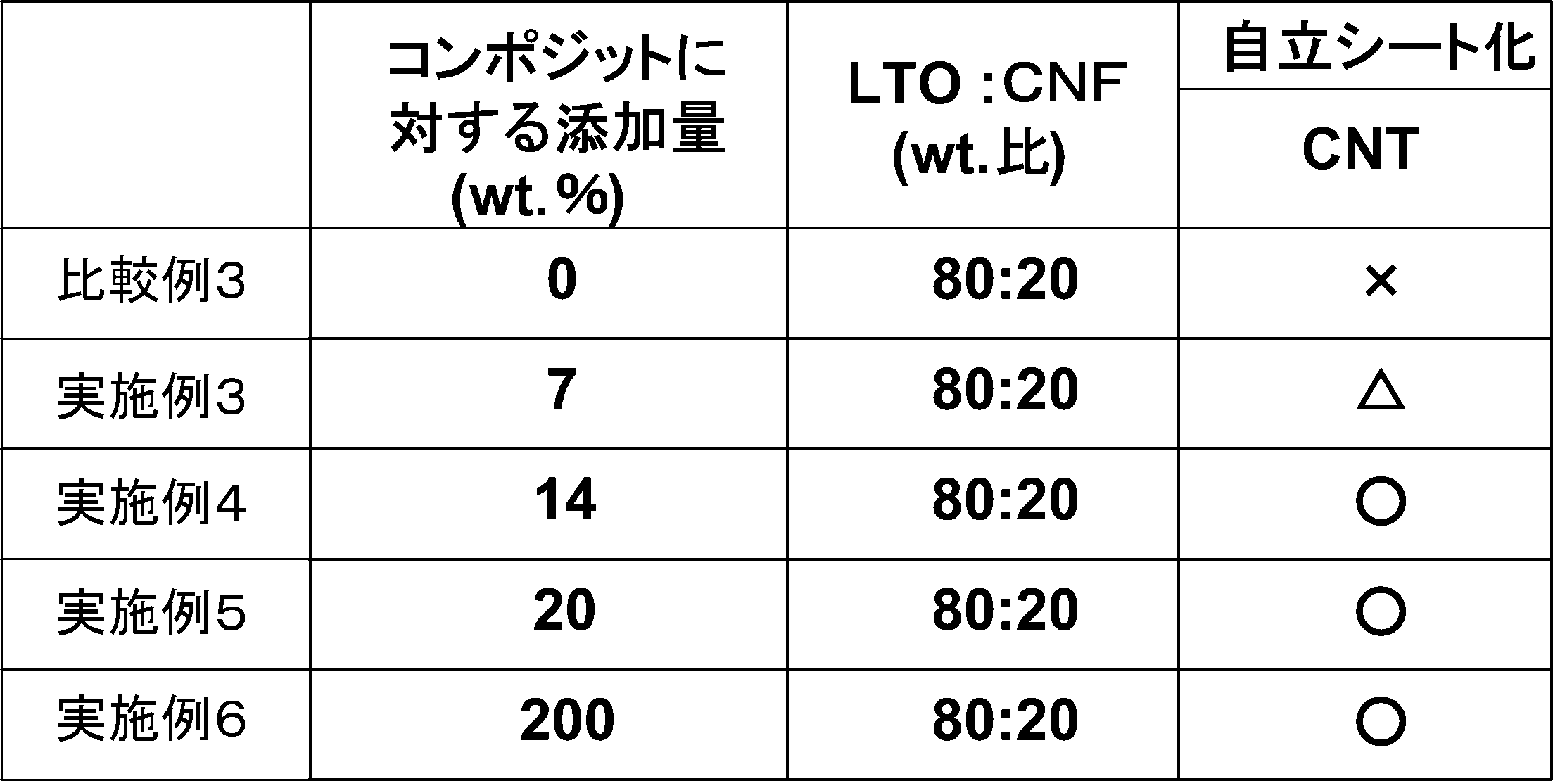
- Comparative Example 3 As in Comparative Example 1, an attempt was made to produce a sheet electrode without using a binder during papermaking molding. In Examples 3 to 6 and Comparative Example 3, the amounts of lithium titanate nanopowder and CNF were adjusted so that the ratio of lithium titanate to CNF was 80:20.
- Comparative Example 3 As is apparent from Table 2, in Comparative Example 3, it can be seen that the sheet is not integrated and is not independent. In the sheet of Example 3, when the surface of the sheet is observed, the surface can be uneven. However, although there is unevenness, the sheet is self-supporting. In the sheets of Examples 4 to 6, the composite material of particulate LTO and CNF became uniform by the fibrous CNT binder, and the sheet was free from unevenness.
- the amount of CNT added as a binder is desirably 10 wt% or more based on the composite material. Furthermore, a more appropriate sheet can be produced by setting the amount of CNT to 14 wt% or more.
- the amount of LTO added it is desirable that the amount of LTO added be large in order to improve the capacity density. Therefore, it is desirable that the amount of CNT added as a binder is 50 wt% or less. For a higher capacity density, a sheet with a high capacity density can be produced by setting the amount of CNT to 25 wt% or less.
- Example 7 a composite material of lithium iron phosphate (hereinafter, LFP) and CNF was used as a composite material of a metal compound and a carbon material.
- Example 8 a composite material of LFP and KB was used as a composite material of a metal compound and a carbon material. 20 wt% of CNT and IPA were added as binders to these composite materials and stirred to prepare a mixed solution. This mixed solution was filtered under reduced pressure using PTFE filter paper (diameter: 35 mm, average pore 0.2 ⁇ m). Thereafter, the mixed solution that had been filtered under reduced pressure was subjected to papermaking to obtain a sheet-like composite having a thickness of 40 to 45 ⁇ m.
- PTFE filter paper diameter: 35 mm, average pore 0.2 ⁇ m
- the formed sheet composite was subjected to a rolling process, and the sheet composite was pressed and integrated on an etched aluminum foil to prepare an electrode.
- This electrode and a lithium foil as a counter electrode are opposed to each other through a separator, and an electrolytic solution in which 1 mol of LiBF 4 as an electrolyte is added to 1 L of propylene carbonate (PC) solvent as an electrolytic solution (1M LiBF 4 / PC).
- an electrochemical cell was prepared.
- Comparative Example 4 In Comparative Example 4, a composite material of LFP and CNF was used as a composite material of a metal compound and a carbon material.
- Comparative Example 5 In Comparative Example 5, a composite material of LFP and KB was used as a composite material of a metal compound and a carbon material. PVDF which is an organic binder as a binder was mixed with these composite materials at 5 wt% to prepare a mixed solution, and a coating electrode in which a coating layer was formed on the surface of the aluminum foil by this mixed solution was prepared.
- This electrode and a lithium foil as a counter electrode are opposed to each other through a separator, and an electrolytic solution in which 1 mol of LiBF 4 as an electrolyte is added to 1 L of propylene carbonate (PC) solvent as an electrolytic solution (1M LiBF 4 / PC).
- an electrochemical cell was prepared.
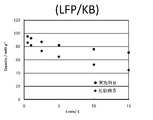
- FIG. 4 is a graph showing the rate characteristics of an electrode using a composite material of LFP and CNF.
- FIG. 5 is a diagram showing the rate characteristics of an electrode using a composite material of LFP and KB.
- Example 7 in which fibrous carbon was added as a binder to the composite material had a higher rate than Comparative Example 4 in which an organic binder was added as a binder. It can be seen that it exhibits characteristics.
- Example 8 in which fibrous carbon is added as a binder to the composite material is higher than Comparative Example 5 in which an organic binder is added as a binder. It can be seen that it shows rate characteristics.
- sheet-like composites and composites having high rate characteristics can be obtained by adding fibrous carbon as a binder to a composite material using LFP as a metallized compound and CNF or KB as a carbon material.
- the used electrodes and electrochemical elements can be formed.
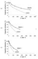
- Example 9 The thickness of the sheet composite formed in Example 2 was set in each of Examples 9 to 11 to produce an electrochemical cell.
- the thickness of the sheet composite formed by papermaking was 23 ⁇ m.
- the thickness of the sheet composite formed by papermaking was set to 50 ⁇ m.
- the thickness of the sheet composite formed by papermaking was 71 ⁇ m.
- Comparative Examples 6 to 8 In the same manner as in Comparative Example 2, the thickness of the coating layer of the coating electrode using CMC as a binder was respectively set to produce an electrochemical cell. In Comparative Example 6, the thickness of the coating layer of the coating electrode was 23 ⁇ m. In Comparative Example 7, the thickness of the coating layer of the coating electrode was 50 ⁇ m. In Comparative Example 8, the thickness of the coating layer of the coating electrode was 71 ⁇ m.
- Example 12 and Comparative Example 9 used in the sixth characteristic comparison are as follows. In this characteristic comparison, LTO is used as a metal compound and CNF is used as a carbon material, and CNT is used as fibrous carbon added as a binder to the composite material.
- Example 12 In Example 12, the thickness of the sheet-like composite formed in Example 4 was set. (Comparative Example 9) In Comparative Example 9, as in Comparative Example 2, the thickness of the coating layer of the coating electrode using CMC as a binder was set.
- Example 12 and Comparative Example 9 fabricated as described above, when charge / discharge measurement was performed at an electrode potential of 1.0 to 3.0 V and a C rate of 200 C, the results shown in FIG. 7 were obtained. It was.
- FIG. 7 shows the capacity utilization in the thickness of the sheet-like composite and the coating layer.
- FIG. 7 is a comparison of rate characteristics between Example 12 and Comparative Example 9.
- Example 12 shows higher evaluation of rate characteristics. I understand that.
- the thickness of the sheet composite is less than 20 ⁇ m, the effect of adding CNT as a binder is reduced.
- the thickness of the sheet composite exceeds 50 ⁇ m, the rate characteristics deteriorate as shown in FIG.
- the thickness of the sheet-like composite is desirably 20 ⁇ m to 50 ⁇ m.
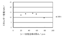
- FIG. 8 shows that in the charge / discharge measurement at 100 C, the energy density peaks when the thickness of the sheet composite is 50 ⁇ m. It can also be seen that high energy density is maintained even when the thickness of the sheet-like composite is 20 ⁇ m and 60 ⁇ m. When the thickness of the sheet composite exceeds 60 ⁇ m and increases to 80 ⁇ m, the energy density is lowered. This is considered to be that if the thickness of the sheet-like composite becomes too large, the resistance increases accordingly, and as a result, the energy density decreases. Accordingly, the thickness of the sheet composite is preferably 20 ⁇ m to 60 ⁇ m. In consideration of the sixth characteristic comparison (FIG. 7), since the rate characteristic improves as the thickness of the sheet-like composite decreases, the thickness of the sheet-like composite takes into account the rate characteristic and the energy density in FIG. Is most preferably 20 ⁇ m to 40 ⁇ m.
Landscapes
- Chemical & Material Sciences (AREA)
- Engineering & Computer Science (AREA)
- Chemical Kinetics & Catalysis (AREA)
- Electrochemistry (AREA)
- General Chemical & Material Sciences (AREA)
- Materials Engineering (AREA)
- Power Engineering (AREA)
- Manufacturing & Machinery (AREA)
- Composite Materials (AREA)
- Organic Chemistry (AREA)
- Microelectronics & Electronic Packaging (AREA)
- Inorganic Chemistry (AREA)
- Life Sciences & Earth Sciences (AREA)
- Environmental & Geological Engineering (AREA)
- General Life Sciences & Earth Sciences (AREA)
- Geology (AREA)
- Crystallography & Structural Chemistry (AREA)
- Nanotechnology (AREA)
- Battery Electrode And Active Subsutance (AREA)
Abstract
Description
(1)コンポジット材料の複合化処理において、炭素材料に金属化合物の出発原料を加えて、メカノケミカル反応の一つである超遠心力処理(Ultra-Centrifugal force processing method:以下、UC処理という)し、金属化合物と炭素材料とのコンポジット材料を作製する。
(2)コンポジット材料のシート化処理において、このコンポジット材料に対してバインダーとして繊維状炭素と溶媒を加え、攪拌することにより混合溶液を作製し、この混合溶液を抄紙成型してシート状複合体を作製する。
以下、本実施形態で使用する金属化合物、炭素材料及び繊維状炭素について説明すると共に、(1)(2)の製造工程について詳述する。
(金属化合物)
本実施形態で使用する金属化合物の一例としては、LiαMβYγである(a)(M=Co,Ni,Mn,Ti,Si,Sn,Al,Zn,Mg、Y=O)、LiCoO2、Li4Ti5O12、SnO2、SiOなどの酸化物系の金属化合物、(b)(M=Fe,Mn,V、Y=PO4,SiO4,BO3,P2O7)などの酸素酸塩系の金属化合物、(c)(M=Ni,Co,Cu、Y=N)、Li2.6Co0.4Nなどの窒化物の金属化合物を使用することができる。それに加えて、MαM'βであるSi、Sn、Geなど金属、(M=Sn,Sb,Si、M'=Fe,Co,Mn,V,Ti) Sn3V2、Sb3Coなどの合金を使用することができる。
本実施形態で使用する炭素材料としては、繊維構造であるカーボンナノチューブ(以下、CNTとする)やカーボンナノファイバー(以下、CNFとする)、中空シェル状の構造を有するカーボンブラックであるケッチェンブラック(以下、KBとする)、アセチレンブラック等のカーボンブラック、無定形炭素、炭素繊維、天然黒鉛、人造黒鉛、活性炭、メソポーラス炭素などがある。この炭素材料は、金属化合物の出発原料と混合しUC処理を行うことでコンポジット材料となる。
本実施形態で使用する繊維状炭素バインダーとしては、繊維径1~10nmのカーボンナノチューブ(以下、CNTとする)を使用する。また、CNT以外には、繊維径10~1000nmのカーボンナノファイバー(以下、CNFとする)及び繊維径1μmを越え、10μm程度、最大100μmの炭素繊維(以下、CFとする)を繊維状炭素として使用することができる。この繊維状炭素は、コンポジット材料に混合することによりコンポジット材料を抄紙成型してシート化する際のバインダーとして作用する。そして、本実施形態に用いる繊維状炭素は、比表面積が600m2/g未満のものを用いる。
(1)コンポジット材料の複合化処理について
本実施処理で使用するコンポジット材料は、炭素材料に金属化合物の出発原料を加えて、UC処理により複合化することにより作製する。また、炭素材料が繊維構造を有する場合(例えば、CNT、CNF)、繊維構造の分散及び均質化を目的として超高圧分散処理を施しても良い。
(a)超高圧分散処理として、繊維構造を有する炭素材料を分散化し、
(b)UC処理として、超高圧分散処理によって分散化された炭素材料に金属化合物の出発原料を加えて、メカノケミカル反応の一つであるUC処理し、
(c)前記(a)(b)の処理を得たその生成物を乾燥し、その後、焼成することにより、金属化合物と炭素材料とのコンポジット材料を作製する。
繊維構造を有する炭素材料を「超高圧分散処理」によって分散化する処理は、
(a)混合処理、(b)超高圧分散処理からなる。
混合処理では、繊維構造を有する炭素材料と溶媒とを混合させ混合溶液を生成する。この炭素材料と溶媒との混合方法は、既存の方法を用いることができる。一例としては、ホモジナイザーによる混合が挙げられる。炭素材料と溶媒は、溶媒1Lに対して、炭素材料0.5~1gの比率が好ましい。
超高圧分散処理では、一般的にジェットミキシング(噴流衝合)と呼ばれる既知の方法を用いる。すなわち、筒状のチャンバの内壁の互いに対向する位置に一対のノズルを設け、高圧ポンプにより加圧された繊維構造を有する炭素材料の混合溶液を、各ノズルから噴射してチャンバ内で正面衝突させる。これにより、炭素材料のバンドルが粉砕され、分散及び均質化することができる。一例としては、炭素材料に対して200MPa,3Pass,0.5g/Lの圧力及び濃度で処理を行う。
UC処理では、前処理を経た炭素材料が分散された混合溶媒に、金属アルコキシド、リチウム化合物及び反応抑制剤を加えて、UC処理をする。UC処理では、超高圧分散処理を経た炭素材料に、金属化合物である金属酸化物活物質の出発原料である金属アルコキシド、リチウム化合物及び反応抑制剤を加えて、メカノケミカル反応の一つであるUC処理をする。以下、金属アルコキシド、リチウム化合物及び反応抑制剤について説明する。
本実施形態で使用する金属アルコキシドとしては、リチウムを吸蔵及び放出可能な金属のアルコキシドを使用する。この金属アルコキシドとしては、チタンアルコキシドが好ましく、その他、金属アルコキシドの加水分解反応の反応速度定数が10-5mol-1sec-1以上のものが好ましい。
リチウム化合物として酢酸リチウム(CH3COOLi、和光純薬工業株式会社製、特級)を用いることができる。酢酸リチウム以外のリチウム源としては、水酸化リチウム、炭酸リチウム、硝酸リチウムなどを利用することができる。リチウム化合物の溶液は、蒸留水、酢酸、イソプロピルアルコールの混合溶液に、酢酸リチウムを溶解させることにより調製できる。
金属アルコキシドとしてチタンアルコキシドを用いた場合、反応が早すぎて、チタン酸リチウムを作製する際に酸化チタンが形成されてしまい、チタン酸リチウムを作製することができない場合があるといった問題点があった。
本実施形態のUC処理は、例えば図9に示すような反応器を用いて行うことができる。図9に示すように、反応器は、開口部にせき板1-2を有する外筒1と、貫通孔2-1を有し旋回する内筒2からなる。この反応器の内筒2内部に反応物を投入し、内筒2を旋回することによってその遠心力で内筒2内部の反応物が内筒2の貫通孔2-1を通って外筒1の内壁1-3に移動する。この時反応物は内筒2の遠心力によって外筒1の内壁1-3に衝突し、薄膜状となって内壁1-3の上部へずり上がる。この状態では反応物には内壁1-3との間のずり応力と内筒2からの遠心力の双方が同時に加わり、薄膜状の反応物に大きな機械的エネルギーが加わることになる。この機械的なエネルギーが反応に必要な化学エネルギー、いわゆる活性化エネルギーに転化するものと思われる。これにより、短時間で反応が進行する。
乾燥・焼成処理では、UC処理を得た生成物(混合物)を真空乾燥し、その後、焼成することにより、金属化合物と炭素材料とのコンポジット材料を作製する。
UC処理によって得られた金属化合物の前駆体を高分散担持した炭素材料の混合溶液を85℃~100℃の範囲で乾燥する。これによって、金属化合物の凝集を防止し、本実施形態の電極材料を使用した電極や電気化学素子の容量、出力特性を向上させる。
乾燥した金属化合物の前駆体を高分散担持した炭素材料を、例えば300℃で1時間、900℃で4分間という二段階焼成によって、金属化合物ナノ粒子が炭素材料に高分散担持された複合体粉末を得る。さらに、900℃の高温で短時間焼成することによって均一な組成の金属化合物が得られる。これにより、金属化合物の凝集を防ぎ、粒径の小さな結晶性のナノ粒子である金属化合物と炭素材料とのコンポジット材料を作製することができる。
シート化処理では、コンポジット材料の複合化処理を経た金属化合物と炭素材料とのコンポジット材料と、バインダーである繊維状炭素とを溶媒に加えて、攪拌することによりスラリー状の混合溶液を生成する。これにより、コンポジット材料及び繊維状炭素とを溶媒中に均一に分散させると共に、繊維状炭素の微砕を行う。この混合溶液を抄紙成型し、減圧乾燥してシート化する。
(a)前処理として、繊維状炭素バインダーを超高圧分散処理によって分散化してもよい。
(b)攪拌処理として、超高圧分散処理によって分散化された繊維状炭素にコンポジット材料を加えた混合溶液を攪拌し、
(c)シート化処理として、該攪拌された混合溶液を抄紙成型し、減圧乾燥してシート化することによりシート状複合体を作製する。
繊維状炭素バインダーを超高圧分散処理によって分散化する前処理は、前述したコンポジット材料の複合化処理における(a)前処理と同様である。この前処理により、繊維状炭素バインダーとIPAとを混合させて混合溶液を生成し、この混合溶液に超高圧分散処理を施して繊維状炭素バインダーが分散化した混合溶液を得る。
前記シート化処理の(a)前処理を経た繊維状炭素バインダーが分散化した混合溶液に、(1)コンポジット材料の複合化処理を経たコンポジット材料を加え、攪拌することによりスラリー状の混合溶液を生成する。
シート化処理では、前記攪拌処理を経た混合溶液を抄紙成型してシート化する。抄紙成型では、混合溶液をPTFE濾紙(直径:35mm、平均細孔0.2μm)を用いて減圧ろ過することによりシートとする。このシートを60℃で、3時間減圧乾燥を行った。以上の処理により、コンポジット材料と繊維状炭素とのシート状複合体を形成することができる。このシート状複合体は必要に応じてプレスなどの圧延処理が施される。
コンポジット材料と繊維状炭素とのシート状複合体を、アルミニウム箔等の金属箔の集電体と同じサイズに切り取り、該集電体の上に載せ、その上から別途用意した金属箔で挟み、金属箔の上下方向から10t/cm2の圧力で1分間プレスすることで、集電体とシート状複合体を一体化させる。この様に集電体と一体化したシート状複合体は、電気化学素子の電極、すなわち電気エネルギー貯蔵用電極とすることができ、その電極は高出力特性、高容量特性を示す。
このシート状複合体及びシート状複合体を用いた電極を用いることができる電気化学素子は、リチウムやマグネシウムなどの金属イオンを含有する電解液を用いる電気化学キャパシタや電池である。すなわち、本実施形態の電極は、金属イオンの吸蔵、脱着を行うことができ、負極や正極として作動する。例えば、本実施形態の電極を、対極となる活性炭、金属イオンが吸蔵、脱着するカーボンや金属酸化物等の電極と、セパレータを挟んで積層し、金属イオンを含有する電解液を用いることによって、電気化学キャパシタや電池を構成することができる。
第1の特性比較では、コンポジット材料に対して添加するバインダーである繊維状炭素バインダーの有無による特性比較を行った。第1の特性比較で使用する実施例1及び比較例1は、以下の通りである。本特性比較では、金属化合物としてLTOと、炭素材料としてCNFを使用し、このコンポジット材料にバインダーとして添加する繊維状炭素としてCNTを使用する。
実施例1は、CNFをジェットミキシングによりIPA中に分散化させた混合溶液を生成し、UC処理を行う反応器の内筒の内部に、該混合溶液、チタンアルコキシド、IPAを投入し、一回目のUC処理を行い、さらにリチウム化合物、反応抑制剤、水を投入して二回目のUC処理を行い、LTOの前駆体を高分散担持したCNFを得た。このLTO前駆体を高分散担持したCNFを90℃で乾燥し、さらに窒素雰囲気中で900℃で焼成することでチタン酸リチウムのナノ粒子がCNFに高分散担持されたコンポジット材料を得た。
次に、CNTバインダーをジェットミキシングによりIPA中に分散化させた混合溶液を生成し、この混合溶液に前記コンポジット材料を加え攪拌することによりスラリー状の混合溶媒を作成し、PTFE濾紙(直径:35mm、平均細孔0.2μm)を用いて減圧ろ過し、抄紙成型してシートを得た後、このシートを60℃で、3時間減圧乾燥を行いシート状複合体を形成した。
比較例1は、実施例1がCNTバインダーを用いて抄紙成型してシート状複合体を形成したのに対し、抄紙成型の際にバインダーを用いないものとし、その他については実施例1と同様とした。
第2の特性比較では、コンポジット材料に対して添加するバインダーの種類による特性比較を行った。第2の特性比較で使用する実施例2及び比較例2は、以下の通りである。本特性比較では、金属化合物としてLTOと、炭素材料としてCNFを使用し、コンポジット材料にバインダーとして添加する繊維状炭素としてCNTを使用する。
実施例2は、実施例1にて形成したシート状複合体を圧延処理し、このシート状複合体をエッチングしたアルミニウム箔にプレスして一体化して電極を作製し、対極となるリチウム箔とをセパレータを介して対向させ、プロピレンカーボネート(PC)溶媒、1Lに、電解質としてLiBF4を1モル添加した(1M LiBF4/PC)電解液を用いて、電気化学セルを作製した。
比較例2は、実施例1に記載のコンポジット材料を、バインダーとして有機バインダーであるカルボキシメチルセルロース(CMC)に混合した混合水溶液を作製し、この混合水溶液をエッチングしたアルミニウム箔に塗布し、溶媒(水)を除去してアルミニウム箔表面にコーティング層を形成したコーティング電極を作製した。このコーティング電極に対極となるリチウム箔とをセパレータを介して対向させ、プロピレンカーボネート(PC)溶媒、1Lに、電解質としてLiBF4を1モル添加した(1M LiBF4/PC)電解液を用いて、電気化学セルを作製した。
このように作製した実施例2及び比較例2のセルについて、電極電位1.0~3.0V、Cレートが100Cでの充放電測定を行ったところ、表1に示すような結果が得られた。

第3の特性比較では、コンポジット材料に対して添加する繊維状炭素バインダーの添加量による特性比較を行った。第3の特性比較で使用する実施例3~6及び比較例3は、以下の通りである。本特性比較では、コンポジット材料としてLTOと、炭素材料としてCNFを使用し、コンポジット材料にバインダーとして添加する繊維状炭素としてCNTを使用する。
実施例3は、実施例1のシート状複合体と同様に作製した。ここでCNTバインダーの添加量をコンポジット材料に対して7wt%となるように配合したシート状複合体とした。
実施例4は、実施例1のシート状複合体と同様に作製した。ここでCNTバインダーの添加量をコンポジット材料に対して14wt%となるように配合したシート状複合体とした。
実施例5は、実施例1のシート状複合体と同様に作製した。ここでCNTバインダーの添加量をコンポジット材料に対して20wt%となるように配合したシート状複合体とした。
実施例6は、実施例1のシート状複合体と同様に作製した。ここでCNTバインダーの添加量をコンポジット材料に対して200wt%となるように配合したシート状複合体とした。
比較例3は、比較例1と同様に、抄紙成型の際にバインダーを用いないでシート電極の作製を試みた。
これら実施例3~6及び比較例3は、チタン酸リチウムとCNFの比が80:20となるようにチタン酸リチウムナノ粉末とCNFの量を調整した。
このようにして作製した実施例3~6及び比較例3のシート状複合体が自立するか試験を行ったところ、表2に示すような結果が得られた。表中の○△×は、作製したシートの状態をしめすものであり、○は表面にムラがない均一で自立したシート、△は表面にムラがあるが自立したシート、×は一体とならずシートを形成してない状態を示す。
第4の特性比較では、金属化合物と炭素材料の種類によるレート特性の比較を行った。第4の特性比較で使用する実施例7、8及び比較例4、5は、以下の通りである。
実施例7は、金属化合物と炭素材料とのコンポジット材料としてリン酸鉄リチウム(以下、LFP)とCNFとのコンポジット材料を使用した。
(実施例8)
実施例8は、金属化合物と炭素材料とのコンポジット材料としてLFPとKBとのコンポジット材料を使用した。
これらのコンポジット材料に対してバインダーとしてCNTを20wt%とIPAとを加え、攪拌することにより混合溶液を作成した。この混合溶液をPTFE濾紙(直径:35mm、平均細孔0.2μm)を用いて減圧ろ過した。その後、減圧ろ過した混合溶液を抄紙成型して厚さを40~45μmのシート状複合体を得た。形成したシート状複合体を圧延処理し、このシート状複合体をエッチングしたアルミニウム箔にプレスして一体化して電極を作製した。この電極と、対極となるリチウム箔とをセパレータを介して対向させ、電解液としてプロピレンカーボネート(PC)溶媒、1Lに、電解質としてLiBF4を1モル添加した(1M LiBF4/PC)電解液を用いて、電気化学セルを作製した。
比較例4は、金属化合物と炭素材料とのコンポジット材料としてLFPとCNFとのコンポジット材料を使用した。
(比較例5)
比較例5は、金属化合物と炭素材料とのコンポジット材料としてLFPとKBとのコンポジット材料を使用した。
これらのコンポジット材料に対してバインダーとして有機バインダーであるPVDFを5wt%混合し混合溶液を作成し、この混合溶液によってアルミニウム箔表面にコーティング層を形成したコーティング電極を作製した。この電極と、対極となるリチウム箔とをセパレータを介して対向させ、電解液としてプロピレンカーボネート(PC)溶媒、1Lに、電解質としてLiBF4を1モル添加した(1M LiBF4/PC)電解液を用いて、電気化学セルを作製した。
このように作製した実施例7、8及び比較例4、5のセルについて、充放電測定を行ったところ、図4、5に示すような結果が得られた。図4は、LFPとCNFとのコンポジット材料を使用した電極のレート特性を示した図である。図5は、LFPとKBとのコンポジット材料を使用した電極のレート特性を示した図である。
第5の特性比較では、コンポジット材料に対して添加するバインダーの有無による特性比較を行った。第5の特性比較で使用する実施例9~11及び比較例6~8は、以下の通りである。本特性比較では、金属化合物としてLTOと炭素材料としてCNFを使用し、コンポジット材料にバインダーとして添加する繊維状炭素としてCNTを使用する。
実施例2にて形成したシート状複合体の厚さを実施例9~11においてそれぞれ設定して、電気化学セルを作製した。実施例9では、抄紙成型したシート状複合体の厚さを23μmとした。実施例10では、抄紙成型したシート状複合体の厚さを50μmとした。実施例11では、抄紙成型したシート状複合体の厚さを71μmとした。
比較例2と同様にCMCをバインダーとしたコーティング電極のコーティング層の厚みをそれぞれ設定して電気化学セルを作製した。比較例6では、コーティング電極のコーティング層の厚さを23μmとした。比較例7では、コーティング電極のコーティング層の厚さを50μmとした。比較例8では、コーティング電極のコーティング層の厚さを71μmとした。
このように作製した実施例9~11及び比較例6~8のセルについて、電極電位1.0~3.0V、Cレート範囲1~500Cでの充放電測定を行ったところ、図6に示すような結果が得られた。図6は、Cレート範囲における容量利用率(Capacity utilization)を示したものである。図6(a)は、実施例9と比較例6とのレート特性の比較、図6(b)は、実施例10と比較例7とのレート特性の比較、図6(c)は、実施例11と比較例8とのレート特性の比較である。
第6の特性比較では、作製したシート状複合体の厚さによる特性比較を行った。第6の特性比較で使用する実施例12及び比較例9は、以下の通りである。本特性比較では、金属化合物としてLTOと炭素材料としてCNFを使用し、コンポジット材料にバインダーとして添加する繊維状炭素としてCNTを使用する。
実施例12では、実施例4にて形成したシート状複合体の厚さをそれぞれ設定した。
(比較例9)
比較例9では、比較例2と同様にCMCをバインダーとしたコーティング電極のコーティング層の厚みをそれぞれ設定した。
このように作製した実施例12及び比較例9のセルについて、電極電位1.0~3.0V、Cレートが200Cでの充放電測定を行ったところ、図7に示すような結果が得られた。図7はシート状複合体及びコーティング層の厚みにおける容量利用率(Capacity utilization)を示したものである。図7は、実施例12と比較例9とのレート特性の比較である。
第7の特性比較では、実施例12のセルに対して、Cレートが100Cでの充放電測定を行った。図8は、シート状複合体の厚みにおけるエネルギー密度を示したものである。
1-2… せき板
1-3… 内壁
2 … 内筒
2-1… 貫通孔
Claims (7)
- 炭素材料にリチウムを吸蔵及び放出可能な金属化合物が担持されたコンポジット材料を
比表面積が600m2/g未満のカーボンナノチューブ、カーボンナノファイバー、炭素繊維のいずれかを含む繊維状炭素バインダーを用いて抄紙成型したことを特徴とするシート状複合体。 - 前記コンポジット材料に対して繊維状炭素バインダーを7wt%~200wt%添加したことを特徴とする請求項1に記載のシート状複合体。
- 前記シート状複合体の厚さが20μm~60μmであることを特徴とする請求項1または請求項2に記載のシート状複合体。
- 請求項1乃至請求項3に記載のシート状複合体を集電体の表面に形成したことを特徴とする電極。
- 請求項4に記載の電極を用いたことを特徴とする電気化学素子。
- 炭素材料にリチウムを吸蔵及び放出可能な金属化合物を担持させたコンポジット材料を得る複合化処理と、
前記コンポジット材料と比表面積が600m2/g未満のカーボンナノチューブ、カーボンナノファイバー、炭素繊維のいずれかを含む繊維状炭素バインダーとを攪拌することにより混合溶液を生成する攪拌処理と、
前記攪拌された混合溶液を抄紙成型してシート状複合体を得るシート化処理と、
を有することを特徴とするシート状複合体の製造方法。 - 前記複合化処理は、旋回する反応器内において、リチウムを吸蔵及び放出可能な金属化合物の出発原料及び炭素材料にずり応力と遠心力を加えて得られた混合物を加熱し、炭素材料にリチウムを吸蔵及び放出可能な金属化合物を担持させたコンポジット材料を得ることを特徴とする請求項6に記載のシート状複合体の製造方法。
Priority Applications (3)
| Application Number | Priority Date | Filing Date | Title |
|---|---|---|---|
| CN201280053227.1A CN103907224A (zh) | 2011-10-29 | 2012-10-29 | 片材状复合体、其制造方法、使用了该复合体的电极及电化学元件 |
| US14/354,941 US20140287314A1 (en) | 2011-10-29 | 2012-10-29 | Sheet composite, manufacturing method thereof, and electrode and electrochemical element employing said composite |
| EP12844324.9A EP2772967A4 (en) | 2011-10-29 | 2012-10-29 | FILM-COMPOSITE COMPOSITE, METHOD OF MANUFACTURING THEREOF AND ELECTRODE AND ELECTROCHEMICAL ELEMENT WITH THIS COMPOSITE |
Applications Claiming Priority (4)
| Application Number | Priority Date | Filing Date | Title |
|---|---|---|---|
| JP2011238057 | 2011-10-29 | ||
| JP2011-238057 | 2011-10-29 | ||
| JP2011238056 | 2011-10-29 | ||
| JP2011-238056 | 2011-10-29 |
Publications (1)
| Publication Number | Publication Date |
|---|---|
| WO2013062126A1 true WO2013062126A1 (ja) | 2013-05-02 |
Family
ID=48167948
Family Applications (1)
| Application Number | Title | Priority Date | Filing Date |
|---|---|---|---|
| PCT/JP2012/077866 Ceased WO2013062126A1 (ja) | 2011-10-29 | 2012-10-29 | シート状複合体、その製造方法、この複合体を用いた電極及び電気化学素子 |
Country Status (5)
| Country | Link |
|---|---|
| US (1) | US20140287314A1 (ja) |
| EP (1) | EP2772967A4 (ja) |
| JP (1) | JPWO2013062126A1 (ja) |
| CN (1) | CN103907224A (ja) |
| WO (1) | WO2013062126A1 (ja) |
Cited By (2)
| Publication number | Priority date | Publication date | Assignee | Title |
|---|---|---|---|---|
| JP2016004786A (ja) * | 2014-06-12 | 2016-01-12 | カウンシル オブ サイエンティフィック アンド インダストリアル リサーチ | Liイオン電池用のフレキシブルで自立したバインダフリーの高性能アノードとしてのカーボンナノチューブ‐金属ナノ複合体 |
| US9832597B2 (en) | 2013-08-04 | 2017-11-28 | Lg Electronics Inc. | Method and apparatus for starting device-to-device operation in wireless communication system |
Families Citing this family (5)
| Publication number | Priority date | Publication date | Assignee | Title |
|---|---|---|---|---|
| CN104616911B (zh) * | 2015-02-02 | 2017-06-16 | 上海理工大学 | 一种垂直碳纳米管阵列/金属氧化物复合材料的制备方法 |
| CN104916834A (zh) * | 2015-06-26 | 2015-09-16 | 田东 | 一种高电压锂离子负极材料的制备方法 |
| CN105551823A (zh) * | 2016-02-02 | 2016-05-04 | 深圳市贝特瑞新能源材料股份有限公司 | 一种碳-碳复合电极材料、制备方法及用途 |
| US10875661B2 (en) * | 2018-12-20 | 2020-12-29 | Airbus Operations Gmbh | Fiber composite component having an integrated structural health sensor arrangement |
| CN110400924B (zh) * | 2019-07-29 | 2021-07-20 | 吉林中溢炭素科技有限公司 | 一种锂离子动力电池负极材料及其制备方法 |
Citations (6)
| Publication number | Priority date | Publication date | Assignee | Title |
|---|---|---|---|---|
| JP2007160151A (ja) | 2005-12-09 | 2007-06-28 | K & W Ltd | 反応方法及びこの方法で得られた金属酸化物ナノ粒子、またはこの金属酸化物ナノ粒子を担持したカーボン及びこのカーボンを含有する電極、並びにこれを用いた電気化学素子。 |
| JP2008270795A (ja) | 2007-03-28 | 2008-11-06 | Nippon Chemicon Corp | 反応方法及びこの方法で得られた金属酸化物ナノ粒子、またはこの金属酸化物ナノ粒子を担持したカーボン及びこのカーボンを含有する電極並びにこの電極を用いた電気化学素子 |
| JP2010044951A (ja) * | 2008-08-12 | 2010-02-25 | Nippon Chemicon Corp | 電極活物質及びこれを用いた電極 |
| JP2010212309A (ja) * | 2009-03-06 | 2010-09-24 | Nippon Chemicon Corp | 電極材料及びこの電極材料を含有する電極 |
| JP2010239097A (ja) * | 2009-03-31 | 2010-10-21 | Nippon Chemicon Corp | 電極活物質及びこれを用いた電極 |
| JP2011216749A (ja) * | 2010-03-31 | 2011-10-27 | Nippon Chemicon Corp | 電気化学キャパシタ |
Family Cites Families (6)
| Publication number | Priority date | Publication date | Assignee | Title |
|---|---|---|---|---|
| KR100570637B1 (ko) * | 2003-05-21 | 2006-04-12 | 삼성에스디아이 주식회사 | 리튬 이차 전지용 음극 활물질 및 그의 제조 방법 |
| US8187754B2 (en) * | 2006-10-11 | 2012-05-29 | Panasonic Corporation | Coin-type non-aqueous electrolyte battery |
| JP5266844B2 (ja) * | 2008-03-31 | 2013-08-21 | 日本ケミコン株式会社 | 電気二重層キャパシタ用電極及びその製造方法 |
| US20110111279A1 (en) * | 2009-11-09 | 2011-05-12 | Florida State University Research Foundation Inc. | Binder-free nanocomposite material and method of manufacture |
| JP5486907B2 (ja) * | 2009-11-18 | 2014-05-07 | 電気化学工業株式会社 | リチウムイオン二次電池用正極材及びその製造方法 |
| WO2011122046A1 (ja) * | 2010-03-31 | 2011-10-06 | 日本ケミコン株式会社 | チタン酸リチウムナノ粒子、チタン酸リチウムナノ粒子とカーボンの複合体、その製造方法、この複合体からなる電極材料、この電極材料を用いた電極、電気化学素子及び電気化学キャパシタ |
-
2012
- 2012-10-29 EP EP12844324.9A patent/EP2772967A4/en not_active Withdrawn
- 2012-10-29 US US14/354,941 patent/US20140287314A1/en not_active Abandoned
- 2012-10-29 CN CN201280053227.1A patent/CN103907224A/zh active Pending
- 2012-10-29 JP JP2013540867A patent/JPWO2013062126A1/ja active Pending
- 2012-10-29 WO PCT/JP2012/077866 patent/WO2013062126A1/ja not_active Ceased
Patent Citations (6)
| Publication number | Priority date | Publication date | Assignee | Title |
|---|---|---|---|---|
| JP2007160151A (ja) | 2005-12-09 | 2007-06-28 | K & W Ltd | 反応方法及びこの方法で得られた金属酸化物ナノ粒子、またはこの金属酸化物ナノ粒子を担持したカーボン及びこのカーボンを含有する電極、並びにこれを用いた電気化学素子。 |
| JP2008270795A (ja) | 2007-03-28 | 2008-11-06 | Nippon Chemicon Corp | 反応方法及びこの方法で得られた金属酸化物ナノ粒子、またはこの金属酸化物ナノ粒子を担持したカーボン及びこのカーボンを含有する電極並びにこの電極を用いた電気化学素子 |
| JP2010044951A (ja) * | 2008-08-12 | 2010-02-25 | Nippon Chemicon Corp | 電極活物質及びこれを用いた電極 |
| JP2010212309A (ja) * | 2009-03-06 | 2010-09-24 | Nippon Chemicon Corp | 電極材料及びこの電極材料を含有する電極 |
| JP2010239097A (ja) * | 2009-03-31 | 2010-10-21 | Nippon Chemicon Corp | 電極活物質及びこれを用いた電極 |
| JP2011216749A (ja) * | 2010-03-31 | 2011-10-27 | Nippon Chemicon Corp | 電気化学キャパシタ |
Non-Patent Citations (1)
| Title |
|---|
| See also references of EP2772967A4 * |
Cited By (2)
| Publication number | Priority date | Publication date | Assignee | Title |
|---|---|---|---|---|
| US9832597B2 (en) | 2013-08-04 | 2017-11-28 | Lg Electronics Inc. | Method and apparatus for starting device-to-device operation in wireless communication system |
| JP2016004786A (ja) * | 2014-06-12 | 2016-01-12 | カウンシル オブ サイエンティフィック アンド インダストリアル リサーチ | Liイオン電池用のフレキシブルで自立したバインダフリーの高性能アノードとしてのカーボンナノチューブ‐金属ナノ複合体 |
Also Published As
| Publication number | Publication date |
|---|---|
| EP2772967A1 (en) | 2014-09-03 |
| US20140287314A1 (en) | 2014-09-25 |
| CN103907224A (zh) | 2014-07-02 |
| JPWO2013062126A1 (ja) | 2015-04-02 |
| EP2772967A4 (en) | 2015-05-20 |
Similar Documents
| Publication | Publication Date | Title |
|---|---|---|
| JP6429458B2 (ja) | 電極材料の製造方法 | |
| JP6922035B2 (ja) | リチウム二次電池電極の製造方法 | |
| JP6040489B2 (ja) | シート状複合体、その製造方法、このシート状複合体を用いた電極及び電気化学素子 | |
| WO2013062126A1 (ja) | シート状複合体、その製造方法、この複合体を用いた電極及び電気化学素子 | |
| JP2010212309A (ja) | 電極材料及びこの電極材料を含有する電極 | |
| JP6621664B2 (ja) | 導電性カーボンの製造方法、このカーボンを含む電極材料の製造方法、この電極材料を用いた電極の製造方法及びこの電極を備えた蓄電デバイスの製造方法 | |
| JP6689741B2 (ja) | 導電性カーボン、この導電性カーボンの製造方法、この導電性カーボンを含む電極材料の製造方法、及びこの電極材料を用いた電極の製造方法 | |
| JP6688840B2 (ja) | 金属化合物粒子群の製造方法、金属化合物粒子群及び金属化合物粒子群を含む蓄電デバイス用電極 | |
| JP6621663B2 (ja) | 導電性カーボンの製造方法、このカーボンを含む電極材料の製造方法、この電極材料を用いた電極の製造方法及びこの電極を備えた蓄電デバイスの製造方法 | |
| CN106463696A (zh) | 电极、该电极的制造方法、具备该电极的蓄电器件、和蓄电器件电极用的导电性碳混合物 | |
| JP6436472B2 (ja) | 導電性カーボンの製造方法、導電性カーボンを含む電極材料の製造方法、及び、電極材料を用いた電極の製造方法 | |
| WO2014077247A1 (ja) | 電極材料の製造方法、電極材料及び該電極材料を備えた蓄電デバイス | |
| JP2019021427A (ja) | カーボンスラリー及びこれを用いた活物質スラリー | |
| JP6319741B2 (ja) | 電極の製造方法 | |
| JP6621586B2 (ja) | 導電性カーボンの製造方法、この導電性カーボンを含む電極材料の製造方法、及びこの電極材料を用いた電極の製造方法 | |
| JP2017091819A (ja) | 電極材料、電極材料の製造方法、および電極材料を備えた蓄電デバイス | |
| JP2017091818A (ja) | 電極材料、電極材料の製造方法、電極、および蓄電デバイス | |
| WO2016098371A1 (ja) | 金属化合物粒子群の製造方法、金属化合物粒子群及び金属化合物粒子群を含む蓄電デバイス用電極 |
Legal Events
| Date | Code | Title | Description |
|---|---|---|---|
| 121 | Ep: the epo has been informed by wipo that ep was designated in this application |
Ref document number: 12844324 Country of ref document: EP Kind code of ref document: A1 |
|
| ENP | Entry into the national phase |
Ref document number: 2013540867 Country of ref document: JP Kind code of ref document: A |
|
| NENP | Non-entry into the national phase |
Ref country code: DE |
|
| WWE | Wipo information: entry into national phase |
Ref document number: 14354941 Country of ref document: US |
|
| REEP | Request for entry into the european phase |
Ref document number: 2012844324 Country of ref document: EP |
|
| WWE | Wipo information: entry into national phase |
Ref document number: 2012844324 Country of ref document: EP |