WO2013065149A1 - 内燃機関の制御装置 - Google Patents
内燃機関の制御装置 Download PDFInfo
- Publication number
- WO2013065149A1 WO2013065149A1 PCT/JP2011/075317 JP2011075317W WO2013065149A1 WO 2013065149 A1 WO2013065149 A1 WO 2013065149A1 JP 2011075317 W JP2011075317 W JP 2011075317W WO 2013065149 A1 WO2013065149 A1 WO 2013065149A1
- Authority
- WO
- WIPO (PCT)
- Prior art keywords
- fuel
- amount
- intake
- valve
- engine
- Prior art date
- Legal status (The legal status is an assumption and is not a legal conclusion. Google has not performed a legal analysis and makes no representation as to the accuracy of the status listed.)
- Ceased
Links
Images


Classifications
-
- F—MECHANICAL ENGINEERING; LIGHTING; HEATING; WEAPONS; BLASTING
- F02—COMBUSTION ENGINES; HOT-GAS OR COMBUSTION-PRODUCT ENGINE PLANTS
- F02D—CONTROLLING COMBUSTION ENGINES
- F02D41/00—Electrical control of supply of combustible mixture or its constituents
- F02D41/0025—Controlling engines characterised by use of non-liquid fuels, pluralities of fuels, or non-fuel substances added to the combustible mixtures
- F02D41/003—Adding fuel vapours, e.g. drawn from engine fuel reservoir
-
- F—MECHANICAL ENGINEERING; LIGHTING; HEATING; WEAPONS; BLASTING
- F02—COMBUSTION ENGINES; HOT-GAS OR COMBUSTION-PRODUCT ENGINE PLANTS
- F02D—CONTROLLING COMBUSTION ENGINES
- F02D19/00—Controlling engines characterised by their use of non-liquid fuels, pluralities of fuels, or non-fuel substances added to the combustible mixtures
- F02D19/06—Controlling engines characterised by their use of non-liquid fuels, pluralities of fuels, or non-fuel substances added to the combustible mixtures peculiar to engines working with pluralities of fuels, e.g. alternatively with light and heavy fuel oil, other than engines indifferent to the fuel consumed
- F02D19/08—Controlling engines characterised by their use of non-liquid fuels, pluralities of fuels, or non-fuel substances added to the combustible mixtures peculiar to engines working with pluralities of fuels, e.g. alternatively with light and heavy fuel oil, other than engines indifferent to the fuel consumed simultaneously using pluralities of fuels
- F02D19/082—Premixed fuels, i.e. emulsions or blends
- F02D19/084—Blends of gasoline and alcohols, e.g. E85
-
- F—MECHANICAL ENGINEERING; LIGHTING; HEATING; WEAPONS; BLASTING
- F02—COMBUSTION ENGINES; HOT-GAS OR COMBUSTION-PRODUCT ENGINE PLANTS
- F02D—CONTROLLING COMBUSTION ENGINES
- F02D41/00—Electrical control of supply of combustible mixture or its constituents
- F02D41/0002—Controlling intake air
- F02D41/0005—Controlling intake air during deceleration
-
- F—MECHANICAL ENGINEERING; LIGHTING; HEATING; WEAPONS; BLASTING
- F02—COMBUSTION ENGINES; HOT-GAS OR COMBUSTION-PRODUCT ENGINE PLANTS
- F02D—CONTROLLING COMBUSTION ENGINES
- F02D41/00—Electrical control of supply of combustible mixture or its constituents
- F02D41/02—Circuit arrangements for generating control signals
- F02D41/04—Introducing corrections for particular operating conditions
- F02D41/12—Introducing corrections for particular operating conditions for deceleration
- F02D41/123—Introducing corrections for particular operating conditions for deceleration the fuel injection being cut-off
-
- F—MECHANICAL ENGINEERING; LIGHTING; HEATING; WEAPONS; BLASTING
- F02—COMBUSTION ENGINES; HOT-GAS OR COMBUSTION-PRODUCT ENGINE PLANTS
- F02M—SUPPLYING COMBUSTION ENGINES IN GENERAL WITH COMBUSTIBLE MIXTURES OR CONSTITUENTS THEREOF
- F02M25/00—Engine-pertinent apparatus for adding non-fuel substances or small quantities of secondary fuel to combustion-air, main fuel or fuel-air mixture
- F02M25/06—Engine-pertinent apparatus for adding non-fuel substances or small quantities of secondary fuel to combustion-air, main fuel or fuel-air mixture adding lubricant vapours
-
- F—MECHANICAL ENGINEERING; LIGHTING; HEATING; WEAPONS; BLASTING
- F01—MACHINES OR ENGINES IN GENERAL; ENGINE PLANTS IN GENERAL; STEAM ENGINES
- F01M—LUBRICATING OF MACHINES OR ENGINES IN GENERAL; LUBRICATING INTERNAL COMBUSTION ENGINES; CRANKCASE VENTILATING
- F01M13/00—Crankcase ventilating or breathing
-
- F—MECHANICAL ENGINEERING; LIGHTING; HEATING; WEAPONS; BLASTING
- F02—COMBUSTION ENGINES; HOT-GAS OR COMBUSTION-PRODUCT ENGINE PLANTS
- F02D—CONTROLLING COMBUSTION ENGINES
- F02D41/00—Electrical control of supply of combustible mixture or its constituents
- F02D41/0002—Controlling intake air
- F02D2041/001—Controlling intake air for engines with variable valve actuation
-
- F—MECHANICAL ENGINEERING; LIGHTING; HEATING; WEAPONS; BLASTING
- F02—COMBUSTION ENGINES; HOT-GAS OR COMBUSTION-PRODUCT ENGINE PLANTS
- F02D—CONTROLLING COMBUSTION ENGINES
- F02D2250/00—Engine control related to specific problems or objectives
- F02D2250/08—Engine blow-by from crankcase chamber
-
- F—MECHANICAL ENGINEERING; LIGHTING; HEATING; WEAPONS; BLASTING
- F02—COMBUSTION ENGINES; HOT-GAS OR COMBUSTION-PRODUCT ENGINE PLANTS
- F02D—CONTROLLING COMBUSTION ENGINES
- F02D2250/00—Engine control related to specific problems or objectives
- F02D2250/11—Oil dilution, i.e. prevention thereof or special controls according thereto
-
- Y—GENERAL TAGGING OF NEW TECHNOLOGICAL DEVELOPMENTS; GENERAL TAGGING OF CROSS-SECTIONAL TECHNOLOGIES SPANNING OVER SEVERAL SECTIONS OF THE IPC; TECHNICAL SUBJECTS COVERED BY FORMER USPC CROSS-REFERENCE ART COLLECTIONS [XRACs] AND DIGESTS
- Y02—TECHNOLOGIES OR APPLICATIONS FOR MITIGATION OR ADAPTATION AGAINST CLIMATE CHANGE
- Y02T—CLIMATE CHANGE MITIGATION TECHNOLOGIES RELATED TO TRANSPORTATION
- Y02T10/00—Road transport of goods or passengers
- Y02T10/10—Internal combustion engine [ICE] based vehicles
- Y02T10/30—Use of alternative fuels, e.g. biofuels
-
- Y—GENERAL TAGGING OF NEW TECHNOLOGICAL DEVELOPMENTS; GENERAL TAGGING OF CROSS-SECTIONAL TECHNOLOGIES SPANNING OVER SEVERAL SECTIONS OF THE IPC; TECHNICAL SUBJECTS COVERED BY FORMER USPC CROSS-REFERENCE ART COLLECTIONS [XRACs] AND DIGESTS
- Y02—TECHNOLOGIES OR APPLICATIONS FOR MITIGATION OR ADAPTATION AGAINST CLIMATE CHANGE
- Y02T—CLIMATE CHANGE MITIGATION TECHNOLOGIES RELATED TO TRANSPORTATION
- Y02T10/00—Road transport of goods or passengers
- Y02T10/10—Internal combustion engine [ICE] based vehicles
- Y02T10/40—Engine management systems
Definitions
- the present invention relates to a control device for an internal combustion engine, and more particularly to a control device for an internal combustion engine having a function of introducing blow-by gas in a crankcase into an intake system.
- FFV Flexible Fuel Vehicle
- the amount of fuel injection is larger than that of gasoline and the volatility of the fuel is reduced, so that the injected fuel tends to adhere to the intake passage and the wall surface in the cylinder. Therefore, the amount of fuel mixed in engine oil (oil dilution amount) also tends to increase. Therefore, when alcohol fuel is used, it is preferable to use a PCV mechanism or the like.
- the PCV mechanism introduces blow-by gas in the crankcase into the intake system as disclosed in, for example, Japanese Patent Application Laid-Open No. 2009-138571, and the blow-by gas introduced into the intake system.
- the amount is adjusted according to the intake negative pressure.
- the fuel evaporated from the engine oil can be burned together with the air-fuel mixture.
- the applicant has recognized the following documents including the above-mentioned documents as related to the present invention.
- the fuel cut is executed in a state where the throttle valve is throttled, for example, during deceleration. For this reason, when the fuel is cut, the intake negative pressure increases, and the amount of blow-by gas introduced into the intake system also tends to increase.
- this blow-by gas since this blow-by gas is under fuel cut, it does not burn in the cylinder but flows out into the exhaust system and reacts with oxygen on the catalyst. Therefore, in an internal combustion engine equipped with a PCV mechanism corresponding to the use of alcohol fuel in the prior art, a large amount of blowby gas reacts with oxygen on the catalyst when the fuel is cut, and the catalyst is likely to deteriorate due to the reaction heat. There's a problem.
- a first invention is a throttle valve that is provided in an intake passage of an internal combustion engine and adjusts an amount of intake air that is sucked into a cylinder through the intake passage;
- a fuel injection valve for injecting alcohol fuel into the intake passage and / or the cylinder;
- a PCV mechanism for introducing evaporative fuel evaporated from lubricating oil into a crankcase of an internal combustion engine into the intake passage;
- Oil dilution amount estimation means for estimating an oil dilution amount that is an amount of fuel mixed in the lubricating oil in the crankcase;
- a fuel-cut throttle control means for setting, based on the oil dilution amount, an opening of the throttle valve when the fuel cut is performed in a state where the PCV mechanism is operated; It is characterized by providing.
- the throttle control means at the time of fuel cut is configured to increase the opening of the throttle valve during fuel cut as the amount of oil dilution increases.
- variable valve mechanism that can change a valve opening characteristic of an intake valve
- the opening of the throttle valve is increased based on the amount of oil dilution, and the rise of the intake negative pressure is suppressed. Can do.
- the amount of blow-by gas that is sucked out of the crankcase by the intake negative pressure and introduced into the intake system can be suppressed.
- attains a catalyst during fuel cut can be suppressed, and generation
- the amount of blow-by gas generated in the crankcase increases as the oil dilution amount increases. For this reason, the larger the oil dilution amount, the smaller the intake negative pressure can be reduced in accordance with the amount of blow-by gas generated by increasing the opening of the throttle valve during fuel cut. Can be prevented.
- the intake valve by delaying the opening timing (IVO) of the intake valve, the intake valve can be closed at the initial stage of the intake stroke, and negative pressure can be generated in the cylinder.
- IVO opening timing
- Embodiment 1 of this invention It is a block diagram for demonstrating the system configuration
- FIG. 1 is a configuration diagram for explaining a system configuration according to the first embodiment of the present invention.
- the system of the present embodiment includes an engine 10 as an internal combustion engine mounted on a vehicle such as an FFV (Flexible Fuel Vehicle).
- the engine 10 can use an alcohol fuel containing, for example, methanol, ethanol, butanol and the like.
- a combustion chamber 14 is formed by a piston 12, and the piston 12 is connected to a crankshaft 16.
- the crankshaft 16 is accommodated in a crankcase 18 (see FIG. 2) provided at the lower part of the engine body.
- the engine 10 also includes an intake passage 20 that sucks intake air into each cylinder and an exhaust passage 22 that discharges exhaust gas from each cylinder.
- an air cleaner 24, a throttle valve 26, and a surge tank 28 are provided in this order from the upstream side.
- the throttle valve 26 adjusts the amount of intake air that is sucked into the combustion chamber 14 (inside the cylinder) via the intake passage 20, and is constituted by an electronically controlled butterfly valve or the like.
- the surge tank 28 constitutes a part of the intake passage 20.
- the exhaust passage 22 is provided with a catalyst 30 such as a three-way catalyst for purifying exhaust gas.
- Each cylinder of the engine 10 has an intake passage 20 (intake port) and fuel injection valves 32 and 34 for injecting fuel into the cylinder, an ignition plug 36 for igniting the air-fuel mixture, and the intake passage 20 in the cylinder.
- an intake valve 38 that opens and closes and an exhaust valve 40 that opens and closes the exhaust passage 22 with respect to the inside of the cylinder are provided.
- the engine 10 also includes a VVT (Variable Valve Timing system) 42 as a variable valve mechanism that can change the valve opening characteristics (opening timing and closing timing) of the intake valve 38.
- VVT Very Valve Timing system
- the VVT 42 has a known configuration as disclosed in, for example, Japanese Unexamined Patent Publication No. 2000-87769, and includes an actuator interposed between the camshaft and the timing pulley.
- the camshaft rotates when the rotation of the crankshaft 16 is transmitted through the timing chain and the timing pulley, and drives the intake valve 38 to open and close.
- the VVT 42 causes the camshaft and the timing pulley to rotate relative to each other by means of an actuator, and the phase of the intake valve 38 is advanced (early) and retarded (slow) according to the relative rotational angle between the two.
- a variable valve mechanism other than the VVT 42 may be used. Specifically, for example, as shown in Japanese Patent Application Laid-Open No.
- the valve opening characteristic of the valve is changed by interposing a roller and a swing arm between the rocker arm and the camshaft of the intake valve 38.
- You may use the variable valve mechanism which makes it possible.
- an electromagnetically driven variable valve mechanism as shown in Japanese Patent Application Laid-Open No. 2007-16710 may be used.
- a mechanism (such as VVL) for changing the operating angle of the intake valve 38 may be a variable valve mechanism.
- FIG. 2 is a configuration diagram showing the PCV mechanism.
- the PCV mechanism 50 includes a gas introduction passage 52, a PCV valve 54, and a fresh air introduction passage 56.
- the gas introduction passage 52 introduces the gas in the crankcase 18 (blow-by gas including evaporated fuel evaporated from the lubricating oil) into the intake passage 20.
- One end of the gas introduction passage 52 is connected to the space in the crankcase 18, and the other end is connected to the intake passage 20 on the downstream side of the throttle valve 26.
- the PCV valve 54 adjusts the amount of blow-by gas introduced from the crankcase 18 to the intake passage 20 via the gas introduction passage 52, and is a negative pressure type flow control valve that opens and closes based on the intake negative pressure. It is comprised by.
- the fresh air introduction passage 56 introduces external air (fresh air) into the crankcase 18 when blow-by gas flows out of the crankcase 18.
- One end of the fresh air introduction passage 56 is connected to the intake passage 20 on the upstream side of the throttle valve 26, and the other end is connected to a space in the crankcase 18.
- the PCV mechanism 50 operates during operation of the engine and introduces the gas in the crankcase 18 into the intake passage 20.
- the negative pressure (intake negative pressure) generated in the intake passage 20 acts on the PCV valve 54, thereby opening the PCV valve 54.
- the intake negative pressure acts on the gas introduction passage 52 and sucks the gas in the crankcase 18 from the gas introduction passage 52 to the intake passage 20. Therefore, by operating the PCV mechanism 50, it is possible to ventilate the gas such as the evaporated fuel accumulated in the crankcase 18, and to burn this gas together with the air-fuel mixture in the cylinder.
- the system of the present embodiment includes a sensor system including sensors 60 to 68, and an ECU (Engine Control Unit) 70 that controls the operating state of the engine.
- the crank angle sensor 60 outputs a signal synchronized with the rotation of the crankshaft 16, and the air flow sensor 62 detects the intake air amount.
- the water temperature sensor 64 detects the temperature of the engine cooling water (engine water temperature)
- the oil temperature sensor 66 detects the temperature of the lubricating oil (lubricating oil temperature)
- the alcohol concentration sensor 68 detects the alcohol concentration in the fuel.
- the engine water temperature and the lubricating oil temperature are examples of the engine temperature that reflects the temperature of the engine.
- the sensor system includes various sensors necessary for engine control (for example, a throttle opening sensor that detects the opening of the throttle valve 26, an accelerator position sensor that detects the operation amount of the accelerator pedal, etc.). ing. These sensors are connected to the input side of the ECU 70. On the other hand, an actuator such as a throttle valve 26, fuel injection valves 32, 34, a spark plug 36, and a VVT 42 is connected to the output side of the ECU 70.
- the ECU70 drives each actuator based on the driving
- the engine speed and the crank angle are detected based on the output of the crank angle sensor 60, and the intake air amount is detected by the air flow sensor 62.
- the engine load is calculated based on the engine speed and the intake air amount
- the fuel injection amount is calculated based on the intake air amount, the engine load, etc.
- the fuel injection amount is corrected based on the engine water temperature, the alcohol concentration in the fuel, the accelerator pedal operation amount, and the like.
- the ECU 70 drives the fuel injection valves 32 and 34 when the fuel injection timing arrives, and drives the spark plug 36 when the ignition timing arrives. Thereby, the air-fuel mixture is combusted in the combustion chamber 14 of each cylinder, and the engine can be operated. Further, the ECU 70 executes various fuel cuts including a known fuel cut during deceleration. In the fuel cut during deceleration, when the engine decelerates with the throttle valve 26 closed, fuel injection is stopped in order to improve emissions and fuel consumption.
- alcohol fuel is used as the fuel for the engine 10, but since the alcohol component in the fuel is highly hydrophilic and lipophilic, it easily adheres to the intake port and the wall surface in the cylinder and is easily mixed into the lubricating oil. . That is, when alcohol fuel is used, the amount of fuel that leaks from the cylinder into the crankcase 18 and enters the lubricating oil (oil dilution amount) tends to increase. In particular, when the engine is operated in a low temperature region below the boiling point of the alcohol component with a high alcohol concentration, the fuel vaporization failure occurs and the amount of fuel adhering to the wall surface. And the increase of oil dilution amount becomes remarkable.
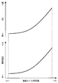
- FIG. 3 is a characteristic diagram showing the distillation characteristics of alcohol components in the fuel (change in distillation ratio with respect to temperature).
- “E0”, “E85”, and “E100” illustrate the cases where the alcohol concentration (ethanol concentration) in the fuel is 0%, 85%, and 100%, respectively.
- the alcohol fuel has a single distillation characteristic as the alcohol concentration in the fuel increases, and is difficult to vaporize even at a low temperature.
- the fuel mixed in the lubricating oil has a characteristic that when the engine is warmed up and the lubricating oil temperature reaches near the boiling point of the alcohol component, it is rapidly vaporized and becomes evaporated fuel. For this reason, when the PCV mechanism 50 is activated and the fuel cut is performed with the catalyst 30 activated, the blow-by gas introduced into the intake system reaches the catalyst without burning in the cylinder, Reacts with oxygen on the catalyst. In this case, the catalyst temperature rises due to the heat of reaction, and a phenomenon (catalyst OT) exceeding the upper limit of heat resistance occurs, which may cause deterioration of the catalyst.
- FC throttle control For this reason, in the present embodiment, when the fuel cut is performed with the PCV mechanism activated, the opening of the throttle valve 26 (throttle opening) during the fuel cut is set to the oil dilution amount (integrated oil dilution amount). Based on the above, the FC throttle control is set to a predetermined opening degree.
- the oil dilution amount estimation process is executed by a known method. More specifically, the ECU 70 learns in advance the relationship between parameters such as lubricating oil temperature, engine load, fuel injection amount, and oil dilution amount, and the oil dilution amount generated in each combustion cycle based on the learning result. Is calculated. Then, by integrating the calculated values, the oil dilution amount (integrated oil dilution amount) at an arbitrary time can be estimated.
- the FC throttle control is executed when all of the following conditions (1) to (3) are satisfied.
- the engine temperature is equal to or higher than a predetermined temperature. Specifically, the engine water temperature ethw is equal to or higher than a predetermined temperature T1, or the lubricant temperature etho is equal to or higher than a predetermined temperature T2.
- the integrated oil dilution amount effeldil is greater than or equal to a predetermined dilution amount determination value.
- the predetermined temperatures T1 and T2 are set, for example, as temperatures at which the amount of fuel evaporated from the lubricating oil suddenly increases (temperature corresponding to the vicinity of the boiling point of the alcohol component described above). That is, when the condition (1) is satisfied, the amount of blow-by gas in the crankcase 18 increases, so that the PCV mechanism 50 needs to be continuously operated. However, when the PCV mechanism 50 is simply operated, A relatively large amount of blow-by gas is introduced into the intake system.
- the dilution amount determination value is set, for example, as the minimum value of the integrated oil dilution amount effeldil that can generate a large amount of blow-by gas under the condition (1).
- the fuel cut execution request corresponds to various fuel cut execution requests including the fuel cut during deceleration, and is determined based on the operating state of the engine. When there is a request to execute fuel cut, fuel injection is stopped and fuel cut is executed.
- FIG. 4 is a characteristic diagram showing the relationship between the integrated oil dilution amount effeldil, throttle opening, and intake negative pressure in FC throttle control. It should be noted that the relationship between the integrated oil dilution amount and the throttle opening described in this figure is stored in advance in the ECU 70 as a data map or the like.
- the integrated oil dilution amount effeldil is larger, the throttle opening during fuel cut is increased. That is, under the assumption that the temperature condition is constant, the amount of blow-by gas generated in the crankcase 18 increases as the integrated oil dilution amount effeldil increases. Therefore, in FC throttle control, the integrated oil dilution amount effeldil is large. The throttle opening during fuel cut is increased and the intake negative pressure is decreased.
- the throttle opening during fuel cut is adjusted according to the amount of blow-by gas generated, and the intake negative pressure is adjusted appropriately. Can be reduced. The amount of blow-by gas that is sucked out of the crankcase 18 by the intake negative pressure and introduced into the intake system can be suppressed. As a result, even if an electromagnetically driven PCV valve is not employed, the amount of blow-by gas that reaches the catalyst 30 during fuel cut can be suppressed, and the generation of the catalyst OT or the like can be prevented.
- the throttle opening during fuel cut may be changed not only according to the integrated oil dilution amount effeldil but also according to the engine water temperature and the lubricating oil temperature. That is, since the amount of blow-by gas generated is considered to increase as these temperatures increase, the throttle opening during fuel cut may be increased as the generated engine water temperature or lubricating oil temperature increases.
- FC intake valve control According to the throttle control during FC, the above-described operational effects can be obtained. However, for example, during execution of fuel cut during deceleration, the pump loss is reduced due to a decrease in intake negative pressure, and the driver feels deceleration. There is a possibility of feeling a drop (decreased drivability). For this reason, the FC intake valve control described below may be used in combination with the FC throttle control.
- FIG. 5 is a characteristic diagram showing a specific example of FC intake valve control.
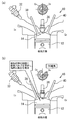
- FIG. 6 is an explanatory diagram showing valve timing and the like of FC intake valve control. 6A shows a normal intake stroke when FC intake valve control is not executed, and FIG. 6B shows an intake stroke when FC intake valve control is executed. ing.
- the intake valve 38 is closed at the initial stage of the intake stroke by retarding the IVO, and negative pressure can be generated in the cylinder.
- the IVO during the fuel cut may be changed according to the engine water temperature and the lubricating oil temperature as well as the integrated oil dilution amount effeldil. That is, the IVO during the fuel cut may be configured to be retarded as the generated engine water temperature or the lubricating oil temperature is higher, corresponding to the throttle opening that increases as these temperatures increase.
- FIG. 7 is a flowchart showing the control executed by the ECU in the first embodiment of the present invention.
- the routine shown in this figure is repeatedly executed while the engine is operating.
- the engine temperature (engine water temperature etw or lubricating oil temperature etho) is acquired.
- step 102 it is determined whether or not the engine temperature acquired in step 100 is equal to or higher than a predetermined temperature.
- step 102 when the engine water temperature ethw is used as the engine temperature, it is determined whether or not the engine water temperature ethw is equal to or higher than the predetermined temperature T1, and when the lubricating oil temperature etho is used, the lubricating oil temperature etho is predetermined. It is determined whether or not the temperature is equal to or higher than T2.
- step 104 an estimated value of the integrated oil dilution amount effeldil estimated by the known method described above is acquired.
- step 106 it is determined whether the integrated oil dilution amount effeldil is equal to or greater than a predetermined dilution amount determination value.
- the FC execution request flag F reflecting the presence or absence of a fuel cut execution request is acquired.
- the FC execution request flag F is set to “1” when there is a fuel cut execution request, and is set to “0” when there is no execution request. It is set based on the operating state.
- step 110 it is determined whether or not the FC execution request flag F is “1”. If this determination is established, the catalyst OT prevention control is executed in step 112.
- the catalyst OT prevention control represents the above-described FC throttle control, or a control in combination with the above FC intake valve control.
- the routine proceeds to step 116 and the normal control (conventional control) in which the catalyst OT prevention control is not executed is executed.
- step 114 the acquired value of the integrated oil dilution amount effeldil is updated, and it is determined whether or not this value is equal to or less than the end determination value.
- the end determination value corresponds to a small value of the integrated oil dilution amount that has been reduced to such an extent that it is not necessary to continue the catalyst OT prevention control. If the determination in step 114 is established, it is determined that the catalyst OT prevention control need not be continued because the oil dilution amount has decreased sufficiently, the catalyst OT prevention control is stopped, and the routine proceeds to step 116. If the determination in step 114 is not satisfied, the oil dilution amount has not decreased sufficiently, so the process returns to step 110 and the catalyst OT prevention control is continued until the determination in step 114 is satisfied.
- step 104 in FIG. 7 shows a specific example of the oil dilution amount estimating means in claim 1, and step 112 in the fuel cut time throttle control means and fuel cut time in claims 1 to 3.
- a specific example of the intake valve control means is shown.
- the throttle opening during fuel cut is increased as the integrated oil dilution amount effeldil increases in the throttle control during FC.
- the throttle opening during the fuel cut may be set based on the oil dilution amount, and the throttle opening during the fuel cut need not necessarily be increased with the oil dilution amount. That is, in the present invention, for example, in some control regions, the throttle opening during fuel cut may be kept constant with respect to changes in the oil dilution amount, and if necessary, the oil dilution amount is reduced. Accordingly, the throttle opening during fuel cut may be increased.
- the alcohol concentration sensor 68 detects the alcohol concentration in the fuel.
- the present invention is not limited to this, and the alcohol concentration in the fuel may be estimated based on the output of an exhaust gas sensor (air-fuel ratio sensor) that detects the exhaust air-fuel ratio.
Landscapes
- Engineering & Computer Science (AREA)
- Chemical & Material Sciences (AREA)
- Combustion & Propulsion (AREA)
- Mechanical Engineering (AREA)
- General Engineering & Computer Science (AREA)
- Oil, Petroleum & Natural Gas (AREA)
- Output Control And Ontrol Of Special Type Engine (AREA)
- Combined Controls Of Internal Combustion Engines (AREA)
- Lubrication Details And Ventilation Of Internal Combustion Engines (AREA)
- Control Of Throttle Valves Provided In The Intake System Or In The Exhaust System (AREA)
- Electrical Control Of Air Or Fuel Supplied To Internal-Combustion Engine (AREA)
Abstract
Description
尚、出願人は、本発明に関連するものとして、上記の文献を含めて、以下に記載する文献を認識している。
前記吸気通路及び/又は前記筒内にアルコール燃料を噴射する燃料噴射弁と、
内燃機関のクランクケース内で潤滑油から蒸発した蒸発燃料を前記吸気通路に導入するPCV機構と、
前記クランクケース内の潤滑油に混入した燃料の量であるオイル希釈量を推定するオイル希釈量推定手段と、
前記PCV機構を作動させた状態で燃料カットを実行するときに、燃料カット中における前記スロットルバルブの開度を、前記オイル希釈量に基いて設定する燃料カット時スロットル制御手段と、
を備えることを特徴とする。
燃料カット中において、前記オイル希釈量が大きいほど、前記可変動弁機構により前記吸気バルブの開弁時期を遅角させる燃料カット時吸気バルブ制御手段と、を備える。
[実施の形態1の構成]
以下、図1乃至図7を参照しつつ、本発明の実施の形態1について説明する。図1は、本発明の実施の形態1のシステム構成を説明するための構成図である。なお、図1では、後述するPCV機構50の記載を省略している。本実施の形態のシステムは、FFV(Flexible Fuel Vehicle)等の車両に搭載される内燃機関としてのエンジン10を備えている。エンジン10は、例えばメタノール、エタノール、ブタノール等を含むアルコール燃料の使用が可能となっている。
本実施の形態では、エンジン10の燃料としてアルコール燃料を使用するが、燃料中のアルコール成分は親水性及び親油性が高いため、吸気ポートや筒内の壁面に付着して潤滑油に混入し易い。即ち、アルコール燃料を用いる場合には、筒内からクランクケース18内に漏出して潤滑油に混入する燃料の量(オイル希釈量)が増加する傾向がある。特に、高濃度のアルコール濃度を使用した状態で、アルコール成分の沸点以下の低温領域でエンジンを運転する場合(始動時等)には、燃料の気化不良が発生し、壁面に付着する燃料の量やオイル希釈量の増加が顕著となる。ここで、図3は、燃料中のアルコール成分の蒸留特性(温度に対する蒸留割合の変化)を示す特性線図である。この図において、「E0」、「E85」、「E100」は、それぞれ燃料中のアルコール濃度(エタノール濃度)が0%、85%、100%の場合を例示している。図3に示すように、アルコール燃料は、燃料中のアルコール濃度が高いほど単一的な蒸留特性をもつようになり、低温でも気化し難くなる。
このため、本実施の形態では、PCV機構を作動させた状態で燃料カットを行うときに、燃料カット中におけるスロットルバルブ26の開度(スロットル開度)を、オイル希釈量(積算オイル希釈量)に基いて所定の開度に設定するFC時スロットル制御を実行する。なお、上記制御において、オイル希釈量の推定処理は公知の方法により実行される。詳しく述べると、ECU70は、例えば潤滑油温、機関負荷、燃料噴射量等のパラメータとオイル希釈量との関係を予め学習しておき、この学習結果に基いて個々の燃焼サイクルで生じるオイル希釈量を算出する。そして、この算出値を積算することにより、任意の時点におけるオイル希釈量(積算オイル希釈量)を推定することができる。
(1)機関温度が所定温度以上である。具体的には、エンジン水温ethwが所定温度T1以上であるか、または、潤滑油温ethoが所定温度T2以上である。
(2)積算オイル希釈量effeldilが所定の希釈量判定値以上である。
(3)燃料カットの実行要求がある。
FC時スロットル制御によれば、上述のような作用効果が得られるものの、例えば減速時燃料カットの実行中には、吸気負圧が低下することによりポンプ損失が減少し、運転者が減速感の低下(運転性の低下)を感じる可能性がある。このため、FC時スロットル制御の実行時には、以下に述べるFC時吸気バルブ制御を併用する構成としてもよい。図5は、FC時吸気バルブ制御の具体例を示す特性線図である。
次に、図7を参照して、本発明の実施の形態1を実現するための具体的な処理について説明する。図7は、本発明の実施の形態1において、ECUにより実行される制御を示すフローチャートである。この図に示すルーチンは、エンジンの運転中に繰返し実行されるものとする。図7に示すルーチンでは、まず、ステップ100において、機関温度(エンジン水温ethwまたは潤滑油温etho)を取得する。ステップ102では、ステップ100で取得した機関温度が所定温度以上であるか否かを判定する。即ち、ステップ102では、機関温度としてエンジン水温ethwを用いる場合に、エンジン水温ethwが所定温度T1以上であるか否かを判定し、潤滑油温ethoを用いる場合には、潤滑油温ethoが所定温度T2以上であるか否かを判定する。
12 ピストン
14 燃焼室
16 クランク軸
18 クランクケース
20 吸気通路
22 排気通路
24 エアクリーナ
26 スロットルバルブ
28 サージタンク
30 触媒
32,34 燃料噴射弁
36 点火プラグ
38 吸気バルブ
40 排気バルブ
42 VVT(可変動弁機構)
50 PCV機構
52 ガス導入通路
54 PCVバルブ
56 新気導入通路
60 クランク角センサ
62 エアフローセンサ
64 水温センサ
66 油温センサ
68 アルコール濃度センサ
70 ECU
Claims (3)
- 内燃機関の吸気通路に設けられ、前記吸気通路を介して筒内に吸込まれる吸入空気の量を調整するスロットルバルブと、
前記吸気通路及び/又は前記筒内にアルコール燃料を噴射する燃料噴射弁と、
内燃機関のクランクケース内で潤滑油から蒸発した蒸発燃料を前記吸気通路に導入するPCV機構と、
前記クランクケース内の潤滑油に混入した燃料の量であるオイル希釈量を推定するオイル希釈量推定手段と、
前記PCV機構を作動させた状態で燃料カットを実行するときに、燃料カット中における前記スロットルバルブの開度を、前記オイル希釈量に基いて設定する燃料カット時スロットル制御手段と、
を備えることを特徴とする内燃機関の制御装置。 - 前記燃料カット時スロットル制御手段は、前記オイル希釈量が大きいほど、燃料カット中における前記スロットルバルブの開度を増加させる構成としてなる請求項1に記載の内燃機関の制御装置。
- 吸気バルブの開弁特性を変更することが可能な可変動弁機構と、
燃料カット中において、前記オイル希釈量が大きいほど、前記可変動弁機構により前記吸気バルブの開弁時期を遅角させる燃料カット時吸気バルブ制御手段と、
を備えてなる請求項1または2に記載の内燃機関の制御装置。
Priority Applications (5)
| Application Number | Priority Date | Filing Date | Title |
|---|---|---|---|
| PCT/JP2011/075317 WO2013065149A1 (ja) | 2011-11-02 | 2011-11-02 | 内燃機関の制御装置 |
| JP2013541542A JP5660228B2 (ja) | 2011-11-02 | 2011-11-02 | 内燃機関の制御装置 |
| EP11874993.6A EP2775127B1 (en) | 2011-11-02 | 2011-11-02 | Control device for internal-combustion engine |
| US14/355,045 US9506412B2 (en) | 2011-11-02 | 2011-11-02 | Control apparatus for internal combustion engine |
| BR112014010408A BR112014010408A2 (pt) | 2011-11-02 | 2011-11-02 | aparelho de controle para motor de combustão interna |
Applications Claiming Priority (1)
| Application Number | Priority Date | Filing Date | Title |
|---|---|---|---|
| PCT/JP2011/075317 WO2013065149A1 (ja) | 2011-11-02 | 2011-11-02 | 内燃機関の制御装置 |
Publications (1)
| Publication Number | Publication Date |
|---|---|
| WO2013065149A1 true WO2013065149A1 (ja) | 2013-05-10 |
Family
ID=48191542
Family Applications (1)
| Application Number | Title | Priority Date | Filing Date |
|---|---|---|---|
| PCT/JP2011/075317 Ceased WO2013065149A1 (ja) | 2011-11-02 | 2011-11-02 | 内燃機関の制御装置 |
Country Status (5)
| Country | Link |
|---|---|
| US (1) | US9506412B2 (ja) |
| EP (1) | EP2775127B1 (ja) |
| JP (1) | JP5660228B2 (ja) |
| BR (1) | BR112014010408A2 (ja) |
| WO (1) | WO2013065149A1 (ja) |
Cited By (6)
| Publication number | Priority date | Publication date | Assignee | Title |
|---|---|---|---|---|
| US20150377098A1 (en) * | 2014-06-27 | 2015-12-31 | Toyota Jidosha Kabushiki Kaisha | Control device for oil pump |
| JP2017061872A (ja) * | 2015-09-24 | 2017-03-30 | トヨタ自動車株式会社 | 内燃機関の制御装置 |
| JP2019060308A (ja) * | 2017-09-27 | 2019-04-18 | 株式会社Subaru | エンジン制御装置 |
| JP2020045790A (ja) * | 2018-09-18 | 2020-03-26 | 日立オートモティブシステムズ株式会社 | 内燃機関の燃料噴射制御装置 |
| JP2020152131A (ja) * | 2019-03-18 | 2020-09-24 | トヨタ自動車株式会社 | 車両の制御装置 |
| JP2020169604A (ja) * | 2019-04-03 | 2020-10-15 | トヨタ自動車株式会社 | 内燃機関の制御装置 |
Families Citing this family (9)
| Publication number | Priority date | Publication date | Assignee | Title |
|---|---|---|---|---|
| JP5847597B2 (ja) * | 2012-01-18 | 2016-01-27 | 本田技研工業株式会社 | 内燃機関の油温センサー取付け構造 |
| DE102012221507B3 (de) * | 2012-10-15 | 2013-11-21 | Continental Automotive Gmbh | Modellierung der Ölverdünnung mit Hilfe eines Mehrkomponentenmodells |
| JP5987764B2 (ja) * | 2013-04-15 | 2016-09-07 | マツダ株式会社 | 火花点火式エンジンの制御装置 |
| JP6375935B2 (ja) * | 2014-12-19 | 2018-08-22 | トヨタ自動車株式会社 | 内燃機関のオイル希釈率算出装置 |
| JP6544366B2 (ja) * | 2017-02-14 | 2019-07-17 | トヨタ自動車株式会社 | 燃料噴射量制御装置 |
| CN108533411B (zh) * | 2018-03-26 | 2020-08-21 | 安徽江淮汽车集团股份有限公司 | 一种可变气门正时控制方法及系统 |
| US11220983B2 (en) * | 2019-04-22 | 2022-01-11 | Zhejiang CFMOTO Power Co., Ltd. | Air intake system for off road vehicle |
| JP7235649B2 (ja) * | 2019-12-20 | 2023-03-08 | 株式会社クボタ | 換気装置付エンジン |
| JP7726185B2 (ja) * | 2022-11-02 | 2025-08-20 | トヨタ自動車株式会社 | 車両 |
Citations (9)
| Publication number | Priority date | Publication date | Assignee | Title |
|---|---|---|---|---|
| JP2000087769A (ja) | 1998-09-09 | 2000-03-28 | Toyota Motor Corp | 内燃機関のバルブ特性制御装置 |
| JP2006132360A (ja) * | 2004-11-04 | 2006-05-25 | Nissan Motor Co Ltd | 内燃機関のブローバイガス処理装置 |
| JP2007016710A (ja) | 2005-07-08 | 2007-01-25 | Hitachi Ltd | 内燃機関の動弁制御システム |
| JP2007132326A (ja) | 2005-11-14 | 2007-05-31 | Toyota Motor Corp | 内燃機関の制御装置 |
| JP2007198196A (ja) | 2006-01-25 | 2007-08-09 | Nissan Motor Co Ltd | 内燃機関 |
| JP2007285239A (ja) | 2006-04-19 | 2007-11-01 | Toyota Motor Corp | 内燃機関の制御装置 |
| JP2009138571A (ja) | 2007-12-04 | 2009-06-25 | Toyota Motor Corp | 内燃機関の制御装置 |
| JP2009222008A (ja) * | 2008-03-18 | 2009-10-01 | Toyota Motor Corp | 車両の制御装置および制御方法 |
| JP2010180774A (ja) * | 2009-02-05 | 2010-08-19 | Nippon Soken Inc | 内燃機関の制御装置 |
Family Cites Families (14)
| Publication number | Priority date | Publication date | Assignee | Title |
|---|---|---|---|---|
| US5402763A (en) * | 1990-11-27 | 1995-04-04 | Fuji Jukogyo Kabushiki Kaisha | Method of controlling an engine for a flexible fuel vehicle |
| EP1586752B1 (en) * | 2004-04-14 | 2008-07-16 | Ford Global Technologies, LLC, A subsidary of Ford Motor Company | Method for controlling the lubricating oil dilution of an internal combustion engine and device for monitoring and reducing this oil dilution |
| JP4466746B2 (ja) * | 2008-02-21 | 2010-05-26 | トヨタ自動車株式会社 | ブローバイガス還元装置の異常診断装置 |
| JP4466754B2 (ja) * | 2008-03-18 | 2010-05-26 | トヨタ自動車株式会社 | 内燃機関の電子制御式ブローバイガス還元装置 |
| JP4745372B2 (ja) * | 2008-06-18 | 2011-08-10 | 三菱電機株式会社 | 内燃機関の始動制御装置 |
| US8141545B2 (en) * | 2008-08-08 | 2012-03-27 | Honda Motor Co., Ltd. | System and method for crankcase gas air to fuel ratio correction |
| JP2010163895A (ja) | 2009-01-13 | 2010-07-29 | Toyota Motor Corp | 内燃機関の吸気制御装置 |
| JP4793453B2 (ja) * | 2009-02-04 | 2011-10-12 | トヨタ自動車株式会社 | 内燃機関の制御装置 |
| WO2010119524A1 (ja) * | 2009-04-15 | 2010-10-21 | トヨタ自動車株式会社 | 可変動弁機構を有する内燃機関の制御装置 |
| JP5549267B2 (ja) * | 2010-02-19 | 2014-07-16 | トヨタ自動車株式会社 | 内燃機関の制御装置 |
| US20130013171A1 (en) * | 2011-07-08 | 2013-01-10 | Fuel Concepts Of America, Inc. | Automotive fuel system |
| US8401764B2 (en) * | 2012-01-18 | 2013-03-19 | Ford Global Technologies, Llc | Fuel identification based on crankshaft acceleration |
| US10570844B2 (en) * | 2012-01-18 | 2020-02-25 | Ford Global Technologies, Llc | Air/fuel imbalance monitor |
| US8838363B2 (en) * | 2012-01-24 | 2014-09-16 | Ford Global Technologies, Llc | Method for injecting fuel |
-
2011
- 2011-11-02 US US14/355,045 patent/US9506412B2/en not_active Expired - Fee Related
- 2011-11-02 WO PCT/JP2011/075317 patent/WO2013065149A1/ja not_active Ceased
- 2011-11-02 BR BR112014010408A patent/BR112014010408A2/pt not_active Application Discontinuation
- 2011-11-02 JP JP2013541542A patent/JP5660228B2/ja not_active Expired - Fee Related
- 2011-11-02 EP EP11874993.6A patent/EP2775127B1/en not_active Not-in-force
Patent Citations (9)
| Publication number | Priority date | Publication date | Assignee | Title |
|---|---|---|---|---|
| JP2000087769A (ja) | 1998-09-09 | 2000-03-28 | Toyota Motor Corp | 内燃機関のバルブ特性制御装置 |
| JP2006132360A (ja) * | 2004-11-04 | 2006-05-25 | Nissan Motor Co Ltd | 内燃機関のブローバイガス処理装置 |
| JP2007016710A (ja) | 2005-07-08 | 2007-01-25 | Hitachi Ltd | 内燃機関の動弁制御システム |
| JP2007132326A (ja) | 2005-11-14 | 2007-05-31 | Toyota Motor Corp | 内燃機関の制御装置 |
| JP2007198196A (ja) | 2006-01-25 | 2007-08-09 | Nissan Motor Co Ltd | 内燃機関 |
| JP2007285239A (ja) | 2006-04-19 | 2007-11-01 | Toyota Motor Corp | 内燃機関の制御装置 |
| JP2009138571A (ja) | 2007-12-04 | 2009-06-25 | Toyota Motor Corp | 内燃機関の制御装置 |
| JP2009222008A (ja) * | 2008-03-18 | 2009-10-01 | Toyota Motor Corp | 車両の制御装置および制御方法 |
| JP2010180774A (ja) * | 2009-02-05 | 2010-08-19 | Nippon Soken Inc | 内燃機関の制御装置 |
Non-Patent Citations (1)
| Title |
|---|
| See also references of EP2775127A4 |
Cited By (10)
| Publication number | Priority date | Publication date | Assignee | Title |
|---|---|---|---|---|
| US20150377098A1 (en) * | 2014-06-27 | 2015-12-31 | Toyota Jidosha Kabushiki Kaisha | Control device for oil pump |
| US10309275B2 (en) * | 2014-06-27 | 2019-06-04 | Toyota Jidosha Kabushiki Kaisha | Control device for oil pump |
| JP2017061872A (ja) * | 2015-09-24 | 2017-03-30 | トヨタ自動車株式会社 | 内燃機関の制御装置 |
| JP2019060308A (ja) * | 2017-09-27 | 2019-04-18 | 株式会社Subaru | エンジン制御装置 |
| JP2020045790A (ja) * | 2018-09-18 | 2020-03-26 | 日立オートモティブシステムズ株式会社 | 内燃機関の燃料噴射制御装置 |
| JP7145018B2 (ja) | 2018-09-18 | 2022-09-30 | 日立Astemo株式会社 | 内燃機関の燃料噴射制御装置 |
| JP2020152131A (ja) * | 2019-03-18 | 2020-09-24 | トヨタ自動車株式会社 | 車両の制御装置 |
| JP7176448B2 (ja) | 2019-03-18 | 2022-11-22 | トヨタ自動車株式会社 | 車両の制御装置 |
| JP2020169604A (ja) * | 2019-04-03 | 2020-10-15 | トヨタ自動車株式会社 | 内燃機関の制御装置 |
| US11028788B2 (en) | 2019-04-03 | 2021-06-08 | Toyota Jidosha Kabushiki Kaisha | Control device for internal-combustion engine |
Also Published As
| Publication number | Publication date |
|---|---|
| US20140303875A1 (en) | 2014-10-09 |
| BR112014010408A2 (pt) | 2017-04-25 |
| JP5660228B2 (ja) | 2015-01-28 |
| EP2775127A1 (en) | 2014-09-10 |
| US9506412B2 (en) | 2016-11-29 |
| JPWO2013065149A1 (ja) | 2015-04-02 |
| EP2775127B1 (en) | 2017-06-28 |
| EP2775127A4 (en) | 2015-12-30 |
Similar Documents
| Publication | Publication Date | Title |
|---|---|---|
| JP5660228B2 (ja) | 内燃機関の制御装置 | |
| US9988994B2 (en) | Systems and methods for EGR control | |
| US8960133B2 (en) | Liquid injection for scavenging | |
| JP4321445B2 (ja) | 内燃機関の制御装置 | |
| CN101617114A (zh) | 多种燃料内燃机 | |
| CN104100384B (zh) | 减少由最小脉冲宽度约束导致的富化 | |
| JP2002322934A (ja) | 内燃機関の吸気制御装置 | |
| US11053868B2 (en) | Method and system for determining piston slap | |
| CN104047672B (zh) | 当汽缸停用时控制通过通风系统的空气流的系统和方法 | |
| CN102084109B (zh) | 用于车辆的控制装置 | |
| JP2010180774A (ja) | 内燃機関の制御装置 | |
| JP6534864B2 (ja) | エンジンの制御装置 | |
| JP2013011176A (ja) | 内燃機関の制御装置 | |
| JP2009235946A (ja) | 内燃機関の制御装置 | |
| JP2009133245A (ja) | 内燃機関の制御装置 | |
| JP2012193689A (ja) | 内燃機関の可変動弁機構制御装置 | |
| CN105705750A (zh) | 用于内燃机的控制装置和控制方法 | |
| JP2008286149A (ja) | 内燃機関の制御装置 | |
| JP2011226349A (ja) | 内燃機関 | |
| JP2006329003A (ja) | 内燃機関の二次空気供給装置 | |
| JP2012112263A (ja) | 内燃機関の制御装置 | |
| JP2009162172A (ja) | 内燃機関の制御装置 | |
| JP2026014061A (ja) | エンジンの制御装置 | |
| JP4365230B2 (ja) | 内燃機関運転制御装置 | |
| JP2000320355A (ja) | 内燃エンジンの制御装置 |
Legal Events
| Date | Code | Title | Description |
|---|---|---|---|
| 121 | Ep: the epo has been informed by wipo that ep was designated in this application |
Ref document number: 11874993 Country of ref document: EP Kind code of ref document: A1 |
|
| ENP | Entry into the national phase |
Ref document number: 2013541542 Country of ref document: JP Kind code of ref document: A |
|
| WWE | Wipo information: entry into national phase |
Ref document number: 14355045 Country of ref document: US |
|
| REEP | Request for entry into the european phase |
Ref document number: 2011874993 Country of ref document: EP |
|
| WWE | Wipo information: entry into national phase |
Ref document number: 2011874993 Country of ref document: EP |
|
| NENP | Non-entry into the national phase |
Ref country code: DE |
|
| REG | Reference to national code |
Ref country code: BR Ref legal event code: B01A Ref document number: 112014010408 Country of ref document: BR |
|
| ENP | Entry into the national phase |
Ref document number: 112014010408 Country of ref document: BR Kind code of ref document: A2 Effective date: 20140430 |