WO2013065152A1 - Dispositif de détection, manivelle comportant un dispositif de détection, bicyclette comportant un dispositif de détection, procédé de correction de valeur de tension, programme de correction de valeur de tension et support ayant un programme de correction de valeur de tension enregistré sur celui-ci - Google Patents
Dispositif de détection, manivelle comportant un dispositif de détection, bicyclette comportant un dispositif de détection, procédé de correction de valeur de tension, programme de correction de valeur de tension et support ayant un programme de correction de valeur de tension enregistré sur celui-ci Download PDFInfo
- Publication number
- WO2013065152A1 WO2013065152A1 PCT/JP2011/075325 JP2011075325W WO2013065152A1 WO 2013065152 A1 WO2013065152 A1 WO 2013065152A1 JP 2011075325 W JP2011075325 W JP 2011075325W WO 2013065152 A1 WO2013065152 A1 WO 2013065152A1
- Authority
- WO
- WIPO (PCT)
- Prior art keywords
- voltage
- detection device
- detection
- crank
- voltage value
- Prior art date
- Legal status (The legal status is an assumption and is not a legal conclusion. Google has not performed a legal analysis and makes no representation as to the accuracy of the status listed.)
- Ceased
Links
Images


Classifications
-
- G—PHYSICS
- G01—MEASURING; TESTING
- G01L—MEASURING FORCE, STRESS, TORQUE, WORK, MECHANICAL POWER, MECHANICAL EFFICIENCY, OR FLUID PRESSURE
- G01L3/00—Measuring torque, work, mechanical power, or mechanical efficiency, in general
- G01L3/02—Rotary-transmission dynamometers
- G01L3/14—Rotary-transmission dynamometers wherein the torque-transmitting element is other than a torsionally-flexible shaft
- G01L3/1407—Rotary-transmission dynamometers wherein the torque-transmitting element is other than a torsionally-flexible shaft involving springs
- G01L3/1428—Rotary-transmission dynamometers wherein the torque-transmitting element is other than a torsionally-flexible shaft involving springs using electrical transducers
- G01L3/1457—Rotary-transmission dynamometers wherein the torque-transmitting element is other than a torsionally-flexible shaft involving springs using electrical transducers involving resistance strain gauges
-
- G—PHYSICS
- G01—MEASURING; TESTING
- G01B—MEASURING LENGTH, THICKNESS OR SIMILAR LINEAR DIMENSIONS; MEASURING ANGLES; MEASURING AREAS; MEASURING IRREGULARITIES OF SURFACES OR CONTOURS
- G01B7/00—Measuring arrangements characterised by the use of electric or magnetic techniques
- G01B7/16—Measuring arrangements characterised by the use of electric or magnetic techniques for measuring the deformation in a solid, e.g. by resistance strain gauge
- G01B7/18—Measuring arrangements characterised by the use of electric or magnetic techniques for measuring the deformation in a solid, e.g. by resistance strain gauge using change in resistance
Definitions
- the present invention relates to a detection device, a crank to which the detection device is attached, a bicycle to which the detection device is attached, a voltage value correction method, a voltage value correction program, and a medium on which the voltage value correction program is recorded.
- a cycle computer that is mounted on a bicycle and calculates and displays information related to the traveling of the bicycle and information related to the movement of the driver.
- the cycle computer calculates predetermined information based on signals transmitted from various sensors provided on the bicycle. For example, by attaching a strain gauge as shown in Patent Document 1 to the crank, the cycle computer measures the force acting on the pedal based on the value detected by the strain gauge, and calculates the overall work rate and torque by pedaling. Calculate and display.
- a strain gauge as described in Patent Document 1 causes a temperature change and a secular change. Therefore, even if calibration (zero point adjustment) is performed at the time of shipment, the zero point (reference point) is shifted during use. End up.
- This invention is made
- An object is to provide a correction method, a voltage value correction program, and a medium on which the voltage value correction program is recorded.
- a detection device includes one or a plurality of strain gauges attached to a crank rotatably connected to a vehicle body, and a voltage for detecting a voltage value output from the strain gauge. It has a detection part, and an adjustment part which adjusts a voltage value in a no-load state of the strain gauge based on a detection value detected by the voltage detection part.
- a voltage value correction method is a first method for detecting a voltage value output from one or more strain gauges attached to a crank rotatably connected to a vehicle body.
- the voltage value correction program provides a computer with a voltage value output from one or more strain gauges attached to a crank that is rotatably connected to a vehicle body.
- a detection function to be detected and an adjustment function to adjust a voltage value in an unloaded state of the strain gauge based on a detection value detected by the detection function are realized.
- (A) is a side view of a bicycle to which a pedaling monitor including a detection device is attached
- (b) is a front view of the bicycle to which the pedaling monitor of FIG. 1 (a) is attached. It is an external view of a cycle computer.
- (A) is a figure showing a mode that the right side measuring device is attached to the right crank
- (b) is a figure showing a mode that the left side measuring device is attached to the left crank.
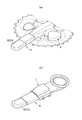
- (A) is a front view of the right-side detection device
- (b) is a cross-sectional view of the right-side detection device
- (c) is a rear view of the right-side detection device. It is a fragmentary sectional view of the detection apparatus for right side.
- (A) is a figure showing the bridge circuit for propulsive power
- (b) is a figure showing the bridge circuit for loss power.
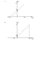
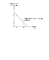
- (A) is an example of the graph showing the shift state of the loss force voltage value at the time of shipment and after shipment
- (b) is an example of the graph showing the shift state of the thrust force voltage value at the time of shipment and after shipment.
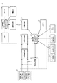
- FIG. 1 (a) shows the calculation of the force that contributes to the rotation of the crank (propulsion force) and the force that does not contribute to the crank rotation (loss force) for every predetermined crank rotation angle by pedaling the bicycle.
- FIG. 1B is a side view showing a state where the pedaling monitor 100 displaying the work rate and torque performed by the driver is attached to the bicycle B, and FIG. 1B shows a state where the pedaling monitor 100 is attached to the bicycle B. It is a front view.
- the bicycle B has a vehicle body frame B1 and two wheels B2 (front wheel B21 and rear wheel B22) that support the frame B1 movably by being pivotally supported by the frame B1 before and after the bicycle B.
- the driving mechanism B3 transmits a propulsive force for propelling the bicycle B to the rear wheel B22, the handle B4 for the driver to steer, and the saddle B5 for the driver to sit on.
- the drive mechanism B3 has a rotating shaft (crankshaft) at one end, and the rotating shaft is rotatably supported at the other end of the crank B31 by an aluminum crank B31 that is rotatably supported with respect to the frame B1.
- a chain ring that is pivotally supported by the driver and connected to the crank B31 with the crankshaft at the one end of the pedal B32 and the crank B31 as a common turning shaft, and rotates integrally with the crank B31.
- B34 and a rear sprocket (not shown) arranged so as to rotate integrally with the rear wheel B22 by using the rotation axis of the rear wheel B22 as a common rotation axis, and a chain ring B34 are connected to each other to connect the pedal B32.
- the crank B31 has a right crankshaft B311 disposed on the right side facing the traveling direction of the bicycle B, and a left crankshaft B312 disposed on the left side facing the traveling direction of the bicycle B, and these left and right crankshafts. B311 and B312 are fixed at a point-symmetrical position with the crankshaft as a symmetric point.
- the pedal B32 is also a right pedal B321 that is rotatably supported by a right pedal shaft (not shown) attached to the tip of the right crankshaft B311 and a left pedal attached to the tip of the left crankshaft B312. And a left pedal B322 rotatably supported by a shaft (not shown).
- the right crankshaft B311 and the left crankshaft B312 and the right pedal B321 and the left pedal B322 have the same shape and structure.
- the right-side detection device 3 and the left-side detection device 4 each have a force that contributes to the rotation of the crank B31 (hereinafter referred to as “propulsion force”) and a force that does not contribute to the rotation of the crank B31 (hereinafter referred to as “loss force”). ) Separately.
- the pedaling monitor 100 detects a predetermined crank rotation angle on the right foot side based on a detection signal (detection value) detected and transmitted by the crank rotation angle detection device 2, the right detection device 3, and the left detection device 4.
- the pedal acting force and the amount of work and torque performed by the driver are calculated and transmitted to the cycle computer 1, and the pedal working force and the driver at a predetermined crank rotation angle on the left foot side are transmitted to the cycle computer 1.
- the left side measuring device 7 that calculates the work amount and torque and transmits it to the cycle computer 1 and the cycle computer 1 that displays the work amount and torque at a predetermined crank rotation angle for each foot are provided.
- the right measuring device 6 is fixed to the chain ring B34, and the left measuring device 7 is fixed to the left crankshaft B312 (see FIG. 3).
- the detection devices 2 to 5 and the measurement devices 6 to 7 are connected by wire.
- the cycle computer 1 is fixed to the handle B4, and the cycle computer 1, the right side measuring device 6 and the left side measuring device 7 are provided with a transmitter (not shown) and are connected to each other wirelessly. ing.
- the crank rotation angle detection device 2 includes a sensing unit 21 provided with a magnet group in which a plurality of magnets are arranged in a circle at predetermined intervals, and a magnetic sensor that detects the sensing unit 21 including the magnet group. And a sensing unit 22 provided.
- the sensed part 21 is fixed to the side surface of the frame B1 so as to face the right crankshaft B311.
- the sensing part 22 is fixed to the chain ring B34 and rotates together with the crank B31.
- the to-be-sensed part 21 is integrated in the measurement apparatus 6 for right side, and is integrated.
- the sensing unit 22 detects each magnet in the magnet group while rotating, and transmits a crank rotation angle detection signal to the right-side measurement device 6 and the left-side measurement device 7 each time it detects each magnet in the magnet group.
- the right measuring device 6 and the left measuring device 7 can detect the crank rotation angle ( ⁇ ) of the crank B31 based on the crank rotation angle detection signal.
- the right detection device 3 has a sheet shape as a whole, and is wound around the right crankshaft B311.
- the left-side detection device 4 also has a sheet shape as a whole, and is wound around the left crankshaft B312. Since the configuration of the right detection device 3 and the configuration of the left detection device 4 are the same, the right detection device 3 will be described below.
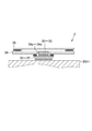
- the right-side detection device 3 is directly attached to the right crankshaft B311 as an underlay for the sensor units 30 to 33 for detecting distortion to be detected and the sensor units 30 to 33.
- the upper waterproof sheet 38 that covers the underlay sheets 34 to 37 and the sensor units 30 to 33 as a whole from the surface side of the sensor units 30 to 33, and the back surface of the upper waterproof sheet 38 and the surface of the right crankshaft B311
- the lower waterproof sheet 39 is provided to block the gap formed between the sensor units 30 to 33.
- the underlay sheets 34 to 37 are made of stretchable (elastic) aluminum plates, and are bonded to the sensor units 30 to 33 on one side (hereinafter referred to as “front surface”), and the other side (hereinafter referred to as “back surface”). ”) And bonded to the strain detection portion of the right crankshaft B311.
- the surface of each of the underlay sheets 34 to 37 is larger than the corresponding sensor unit 30 to 33, and a part of the surface is exposed when the sensor units 30 to 33 are bonded.
- the lower waterproof sheet 39 is bonded to the exposed portion.
- the sensor units 30 to 33 are bonded to the right clan shaft B311 via the stretchable underlay sheets 34 to 37, the sensor units 30 to 33 can be used without degrading the detection function of the sensor units 30 to 33 during use.
- the units 30 to 33 can be detached from the right clan shaft B311 without damaging them. It is desirable that the underlay sheets 34 to 37 are elastically deformed without being plastically deformed when removed from the right crankshaft B311 and have a strength that does not damage the sensor units 30 to 33. This is because the right-side detection device 3 is reused after being removed from the right crankshaft B311.
- the main body 39A is formed with fitting holes 39a to 39d into which the sensor units 30 to 33 are fitted.
- the insertion holes 39a to 39d are arranged side by side in a straight line at a predetermined interval (21 mm in the present embodiment). As shown in FIG.
- the sensor units 30 to 33 and the portion surrounding the sensor units 30 to 33 of the lower waterproof sheet 39 are integrated with the sensor units 30 to 33 inserted into the insertion holes 39a to 39d.
- it is adhered to the underlay sheets 34-37. Therefore, it is possible to prevent intrusion of external enemies such as water from between the lower waterproof sheet 39 and the sensor units 30 to 33.
- the shapes of the respective insertion holes 39a to 39d are substantially the same as the corresponding sensor units 30 to 33, specifically, slightly larger than the sensor units 30 to 33. This makes it possible to reliably prevent the entry of water and other foreign enemies from between the lower waterproof sheet 39 and the sensor units 30 to 33, and the expansion and contraction of the underlying sheets 34 to 37 accompanying the deformation of the right crankshaft B311. This is to prevent the detection accuracy of the right-side detection device 3 from being deteriorated.
- the upper waterproof sheet 38 covers at least the plurality of sensor units 30 to 33 as a whole, and is adhered to the surface of the lower waterproof sheet 39 so as to surround the sensor units 30 to 33 as a whole and individually. In this way, the lower waterproof sheet 39 surrounding the sensor units 30 to 33 is bonded to the underlay sheets 34 to 37, and the gap between the sensor units 30 to 33 and the lower waterproof sheet 39 is blocked, while the upper waterproof sheet is used.
- the sheet 38 is adhered to the underlying sheets 34 to 37 so as to surround the sensor units 30 to 33 so as to cover the sensor units 30 to 33 as a whole, and the gap between the sensor units 30 to 33 and the upper waterproof sheet 38 is blocked. Therefore, the sensor units 30 to 33 are waterproof. Further, by removing the underlay sheets 34 to 37 from the right crankshaft B 311, the right side detection device while maintaining the waterproof function for the sensor units 30 to 33 by the underlay sheets 34 to 37, the upper waterproof sheet 38 and the lower waterproof sheet 39. 3 can be removed from the right crankshaft B311.
- the material of the upper waterproof sheet 38 and the lower waterproof sheet 39 is not particularly limited, but as shown in FIG. 3A, the upper waterproof sheet 38 and the lower waterproof sheet 39 are wound around the right crankshaft B311. It is desirable to have a certain degree of elasticity (that is, bendable) that does not break when wound around the right crankshaft B311. However, for the lower waterproof sheet 39, if the stretchability is higher than a predetermined value, the wiring provided on the lower waterproof sheet 39 may be cut. Therefore, the lower waterproof sheet 39 is less than the predetermined value, specifically, the wiring is not cut. It is desirable to have the elasticity.
- the lower waterproof sheet 39 and the right crankshaft B311 are basically in close contact, but are not bonded. This is because a predetermined tool or the like is inserted between the lower waterproof sheet 39 and the right crankshaft B311 to easily remove the right detection device 3 from the right crankshaft B311.
- the underlying sheets 34 to 37 have a wedge shape, that is, are formed into a taper shape.
- the surface of the underlay sheets 34 to 37 is formed into a square having a side of 9.0 mm, and the back surface is formed into a square having a side of 7.4 mm. Since the underlay sheets 34 to 37 are formed into a taper shape that expands toward the surface side in this way, a predetermined tool can be hooked on the tapered portion of the underlay sheets 34 to 37, and thus easily and The right detection device 3 can be detached from the right crankshaft B311 without damaging other members such as the sensor units 30 to 33 and the lower waterproof sheet 39.
- the right-side detection device 3 is configured to include the underlay sheets 34 to 37 corresponding to the sensor units 30 to 33, but the plurality of sensor units 30 to 33 are pasted together. It can also be set as the structure which comprises the underlay sheet
- the area of the undersheet is preferably small.
- the right-side detection device 3 includes the underlay sheets 34 to 37 corresponding to the sensor units 30 to 33 as in the present embodiment. From the viewpoint of detection sensitivity, it is desirable that the right crankshaft B311 and the underlay sheets 34 to 37 are made of the same material and have the same expansion / contraction coefficient.
- the thickness of the underlay sheet is not particularly limited, but if the thickness is reduced, the stretchability increases, so that the detection sensitivity of the sensor units 30 to 33 is improved. However, as the thickness is reduced, the durability is lowered, and particularly when the right-side detection device 3 is removed, it is easily broken. Therefore, it is desirable that the thickness of the underlay sheet is appropriately set with a good balance in consideration of the balance between detection sensitivity and durability.
- the right-side detection device 3 includes the sensor units 30 to 33, the underlay sheets 34 to 37, the upper waterproof sheet 38, and the lower waterproof sheet 39, which are integrated into the back sheet 34 to 37. Then, it is adhered to the strain detection points (front surface, rear surface, outer surface and inner surface described later) of the right crankshaft B311. As a result, the right-side detection device 3 is wound around the right crankshaft B311 and the sensor units 30 to 33 are attached to the right crankshaft B311 via the underlay sheets 34 to 37. That is, the underlay sheets 34 to 37, the sensor units 30 to 33, and the fitting holes 39a to 39d are provided so that the right detection device 3 is wound around the right crankshaft B311.
- the underlay sheets 34 to 37, the sensor units 30 to 33, and the insertion holes 39a to 39d are provided at positions corresponding to strain detection locations (a front surface, a rear surface, an outer surface, and an inner surface described later).
- strain detection locations a front surface, a rear surface, an outer surface, and an inner surface described later.
- the positions where the underlay sheets 34 to 37, the sensor units 30 to 33, and the fitting holes 39a to 39d are appropriately set according to the shape and structure of the attached crank.
- the sensor units 30 and 31 are used to detect a propulsive force and are attached to the front surface and the rear surface of the right crankshaft B311.
- the sensor units 32 and 33 are used to detect the loss force and are attached to the outer side surface and the inner side surface of the right crankshaft B311. Therefore, in the integrated detection device 3 for the right side, the sensor units 30 and 31 for propulsive force and the sensor units 32 and 33 for loss force are alternately arranged.
- each of the sensor units 30 to 33 of the right-side detection device 3 includes a pair of two strain gauges.
- the sensor unit 30 is attached to a surface (hereinafter referred to as “front surface”) facing forward with respect to the traveling direction of the right crankshaft B311 via an underlay sheet 34.
- the sensor unit 31 is similarly attached to a rearward facing surface (hereinafter referred to as “rear surface”) via a sheet 35.
- the sensor units 30 and 31 are arrow-shaped, and are composed of a pair of strain gauges 30a and 30b and 31a and 31b. Each sensor unit 30 and 31 is oriented in the length direction of the right crankshaft B311. Is pasted with the right pedal B321 facing along.
- the sensor unit 32 is attached to a surface (hereinafter referred to as “outer surface”) facing the outside of the bicycle B with respect to a direction orthogonal to the traveling direction of the right crankshaft B311 via a sheet 36
- the sensor unit 32 33 is attached to a surface (hereinafter referred to as “inside surface”) facing the inside of the bicycle B with respect to a direction orthogonal to the traveling direction via a sheet 37.
- the sensor units 32 and 33 are arrow-shaped and are composed of a pair of strain gauges 32a and 33b and 33a and 33b. The direction of the arrow-shaped arrow is along the length direction of the right crankshaft B311. Affixed with B321 facing.
- the sensor units 30 to 33 are connected to the right measurement device 6 by cables, and the detection values detected by the sensor units 30 to 33 are transmitted to the right measurement device 6 by detection signals.
- the rotation direction of the pedal action force is detected by the sensor units 30 and 31 attached to the front and rear surfaces of the right crankshaft B311, that is, the surfaces receiving the force in the rotation direction of the right crankshaft B311.
- a component propulsive force
- These strain gauges 30a, 30b, 31a and 31b constitute a propulsive force bridge circuit 3A shown in FIG.
- the pair of strain gauges 30a and 30b and the strain gauges 31a and 31b constituting the sensor units 30 and 31 are respectively arranged on opposite sides of the propulsive force bridge circuit 3A.
- the pedal acting force is exerted by the sensor units 32 and 33 attached to the inner and outer surfaces of the right crankshaft B311, that is, the surfaces receiving the force in the inner and outer directions of the right crankshaft B311.
- a radial direction component (loss force) is detected.
- These strain gauges 32a, 32b, 33a, and 33b constitute a loss force bridge circuit 3B shown in FIG. 7B.
- the pair of strain gauges 32a and 32b and the strain gauges 33a and 33b constituting the sensor units 32 and 33 are respectively disposed on opposite sides of the loss force bridge circuit 3B.
- the rotational direction component Fx and the radial direction component Fy of the pedal acting force can be calculated as follows. This calculation is performed by the control unit 60 of the right-side measuring device 6 to which each bridge circuit is connected.
- an amplifier circuit such as an operational amplifier is interposed between the bridge circuits 3A and 3B and the control unit 60, the power values finally acquired by the control unit 60 are set as the following output value X and output value Y. .
- Xz and [Yz] represent output values to the control unit 60 when the right crankshaft B311 is in a no-load state
- Xr and [Yr] represent rotation directions of the right crankshaft B311 of 20 [kgf].
- An output value to the control unit 60 in a state where the component is received and “Xd” and [Yd] are output values to the control unit 60 in a state where the right crankshaft B311 receives a radial direction component of 20 [kgf].
- the cycle computer 1 includes a control unit 10 that performs control, an operation that can be performed, and an input unit 11 that transmits an operation detection signal indicating the operated content to the control unit 10.
- a display unit 12 for displaying predetermined information, a transmission / reception unit 14 for transmitting / receiving predetermined information to / from the right measuring device 6 according to a command from the control unit 10, and a power supply unit 15 for supplying power to the control unit 10.
- the control unit 10 includes a CPU 10a, a ROM 10b, and a RAM 10c.
- the CPU 10a controls basic processing as a cycle computer including display of predetermined parameters related to pedaling and determination processing of a calibration execution condition of the right-side detection device 3 to be described later, based on a program stored in advance in the ROM 10b. To do.
- the ROM 10b stores in advance program codes for executing basic processing as a cycle computer executed by the CPU 10a and determination processing of calibration execution conditions of the right-side detection device 3.
- the RAM 10c functions as a working area for data and the like in arithmetic processing performed when the CPU 10a executes basic processing as a cycle computer and determination processing of calibration execution conditions of the right-side detection device 3.
- the input unit 11 includes operable operation units 11a to 11c (see FIG. 2), converts input signals accompanying operations received by the operation units 11a to 11c into control information corresponding to the operations, and transmits the control information to the control unit 10. To do.
- the operation units 11a and 11c have a button structure that can be pressed, and 11b has a cross key structure.
- the driver can input specific information related to the driver and the bicycle, select execution / non-execution of calibration, which will be described later, and the like by combining the operations of the operation units 11a to 11c.
- the display unit 12 displays, for example, a work rate and torque for each predetermined crank rotation angle for each foot, or a screen for selecting calibration execution when the power is turned on as described later.
- the display unit 12 may be configured with a touch panel, and the input unit 11 and the display unit 12 may be integrated.
- the transmitter / receiver 14 is an interface for transmitting / receiving data to / from an external processing device such as a mobile terminal such as a mobile phone or a PC installed at home or the like, including the right measurement device 6 and the left measurement device 7. It is.
- an external processing device such as a mobile terminal such as a mobile phone or a PC installed at home or the like, including the right measurement device 6 and the left measurement device 7. It is.
- the right measurement device 6 includes a control unit 60 that controls the voltage, a voltage output unit 61 that outputs (adds) a voltage to the voltage output from each bridge circuit 3A and 3B of the right detection device 3, and each bridge circuit 3A and 3B.
- a voltage amplifying unit 62 for amplifying the voltage output from voltage amplifying unit 61 added to the voltage output from voltage, voltage detecting unit 63 for detecting the voltage value of the voltage output from voltage amplifying unit 62, and cycle computer 1 includes a transmission / reception unit 64 that transmits a signal to the cycle computer 1 and a power supply unit 65 that supplies power to the control unit 60.
- Each bridge circuit 3A, 3B is independently connected to the voltage amplifying unit 62.
- the voltage output unit 61 includes a D / A converter, and is connected to a cable that connects each of the bridge circuits 3A and 3B and the voltage amplification unit 62. That is, the voltage output unit 61 can individually add a voltage to the voltage output from the propulsive force bridge circuit 3A and the voltage output from the loss power bridge circuit 3B.
- the voltage amplifying unit 62 is composed of an operational amplifier, and a voltage A obtained by adding the voltage output from the voltage output unit 61 to the voltage output from the propulsive force bridge circuit 3A, and a voltage output from the loss power bridge circuit 3B. And the voltage B obtained by adding the voltage output from the voltage output unit 61 to each other are individually amplified.
- the voltage detection unit 63 is composed of an A / D converter, and can detect the voltage value of the voltage amplified by the voltage amplification unit 62 (hereinafter, amplified based on A output from the bridge circuit 3A).
- the voltage value of the voltage is referred to as “propulsive force voltage value Va”
- the voltage value of the voltage amplified based on the voltage B output from the bridge circuit 3B is referred to as “loss force voltage value Vb”.
- the performance of the voltage detection unit 63 that is an A / D converter is such that the resolution is “10” bits, the maximum input value is “1.5” V, and the sensitivity (slope) is “7. 32 "mV / kgf.
- the control unit 60 includes a CPU 60a, a ROM 60b, and a RAM 60c.
- the CPU 60a controls calibration of the right-side detection device 3 to be described later, based on a program stored in advance in the ROM 60b.
- the ROM 60b stores in advance a program code for executing calibration of the right detection device 3 executed by the CPU 60a.
- the RAM 60c functions as a working area for data and the like in arithmetic processing performed when the CPU 60a performs calibration of the right detection device 3.
- a predetermined execution condition for performing calibration hereinafter referred to as “calibration execution condition”
- the control unit 60 detects each detected value (propulsion voltage value Va, loss) detected by the voltage detection unit 63.
- the voltage output unit 61 is caused to apply a predetermined voltage to the bridge circuits 3A and 3B.
- the determination value is set for each detected value (hereinafter, the determination value for the propulsive force voltage value Va is referred to as “determination value Vs for propulsive force”, and the determination value for the loss force voltage value Vb is “loss power”. For example, determination value Vt). That is, determination values are set for the propulsive force bridge circuit 3A and the loss force bridge circuit 3B.
- the control unit 60 repeats the above processing until the propulsive force voltage value Va and the loss force voltage value Vb exceed the propulsion force determination value Vs and the loss force determination value Vt, respectively.
- the predetermined calibration execution condition will be described later.
- the propulsive force Fx and the loss force Fy will be described separately.
- the loss power Fy will be described.
- the reason why the desired detection range of the propulsive force Fx is biased toward the “+” side is that the right crankshaft B311 (the right pedal B321) is likely to be applied with a positive force (the direction of the rowing) and is negative. This is because the dynamic range in the positive direction of the propulsive force (the rotational direction component of the pedal acting force) is increased to detect the rotational direction component accurately and reliably because it is difficult to apply a direction force. It should be noted that since the negative force is not applied at all, it is desirable to set the negative dynamic range appropriately.
- the control unit 10 causes the display unit 12 to display a screen for selecting execution / non-execution of calibration of the right-side detection device 3 (hereinafter referred to as “calibration selection screen”). .
- calibration selection screen a screen for selecting execution / non-execution of calibration of the right-side detection device 3
- the control unit 10 informs the transmission / reception unit 14 that the execution of calibration has been selected. To send to.
- the control unit 60 of the right-side measuring device 6 receives information from the transmission / reception unit 64 that the execution of calibration has been selected, the control unit 60 executes the calibration described above. That is, the calibration execution condition is “the input unit 11 receives a predetermined operation when the calibration selection screen is displayed on the display unit 12”. That is, calibration is performed manually.
- control unit 10 When the power is supplied from the power supply unit 15, the control unit 10 causes the display unit 12 to display a calibration selection screen in step S10.
- control unit 10 determines whether or not control information is transmitted from the input unit 11 in step S11. If there is no control information, the control unit 10 repeatedly performs the determination. If there is control information, the control unit 10 determines in step S12 whether the control information indicates execution of calibration.
- control unit 10 ends the main process as it is, and when the control information indicates “execution of calibration”, transmission / reception
- the information indicating that “execution of calibration” is selected is sent to the measurement device 6 for the right side, and the main process ends.
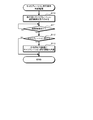
- step S20 the control unit 60 determines whether a propulsion force calibration completion flag, which will be described later, is turned on. If the control unit 60 determines that the propulsion force calibration completion flag is turned on, the control unit 60 proceeds to step S25. If the control unit 60 determines that the propulsion force calibration completion flag is not turned on, the control unit 60 proceeds to the voltage detection unit 63 in step S21. The force voltage value Va is detected.
- step S22 the control unit 60 determines whether or not the propulsive force voltage value Va is greater than or equal to the propulsive force determination value Vs.
- the control unit 60 turns on the driving force calibration completion flag in a predetermined area of the RAM 60c in step S24.
- the control unit 60 supplies a predetermined voltage to the voltage output unit 61 in step S23. Multiply to 3A.
- step S25 the control unit 60 determines whether or not a loss force calibration completion flag, which will be described later, is turned on. If the control unit 60 determines that the loss force calibration completion flag is ON, the process proceeds to step S30. If the control unit 60 determines that the loss force calibration completion flag is not ON, the control unit 60 causes the voltage detection unit 63 to perform loss in step S26. The force voltage value Vb is detected.
- step S27 the controller 60 determines whether or not the loss force voltage value Vb is greater than or equal to the loss force determination value Vt.
- the control unit 60 turns on the loss force calibration completion flag in a predetermined region of the RAM 60c in step S29, and when determining that Vb ⁇ Vt, the control unit 60 applies a predetermined voltage to the voltage output unit 61 in step S28. It is applied to the circuit 3B.
- step S30 the control unit 60 determines whether both the propulsion force calibration completion flag and the loss force calibration completion flag are turned on. If it is determined that both are ON, the control unit 60 ends the calibration execution process, and if it is determined that none is ON, the process returns to step S20.
- the propulsion force calibration completion flag and the loss force calibration completion flag that are turned on by the calibration execution process are turned off at an appropriate timing such as when power is cut off or after step S30.
- the calibration of the right-side detection device 3 by the cycle computer 1 and the right-side measurement device 6 has been described, but the left-side detection is similarly performed by the cycle computer 1 and the left-side measurement device 7. Calibration of the device 4 is performed.
- the right-side detection device 3 is connected to the right-side measurement device 6 including the control unit 60, and the right-side measurement device 6 includes the voltage detection unit 63 and the voltage output unit 61. Calibration can be performed before and the measured value can be measured accurately.
- the pedaling monitor 100 is connected to a pedal such as a non-running exercise bike for training installed in a sports gym or a boat (for example, a swan boat) propelled by pushing a pedal manually, in addition to a bicycle traveling on the road. It can be used for vehicles that rotate the crank.
- a pedal such as a non-running exercise bike for training installed in a sports gym or a boat (for example, a swan boat) propelled by pushing a pedal manually, in addition to a bicycle traveling on the road. It can be used for vehicles that rotate the crank.
- the pedal action force and the average torque are displayed by the cycle computer 1, but the pedal action force and the torque average are displayed by application software of a mobile terminal such as a mobile phone.
- the mobile terminal may be installed on the bicycle B or carried by the driver.
- the calibration selection screen is displayed when the power is turned on, but can be arbitrarily displayed by operating the input unit 11.
- the shape, size, material, and the like of the sensor units 30 to 33, the underlay sheets 34 to 37, the upper waterproof sheet 38, and the lower waterproof sheet of the right-side detection device 3 are not limited to the first embodiment.
- the calibration of the right detection device 3 is not limited to the first embodiment.
- the temperature sensor 9 that detects the temperature is connected to the control unit 60, and the temperature detected by the temperature sensor 9 when performing calibration before use is stored as a reference temperature in a predetermined storage device. After that, the calibration is automatically executed under the condition that the difference between the temperature detected by the temperature sensor and the reference temperature exceeds a predetermined threshold on condition that the power is turned on. You can also make it.
- the temperature sensor 9 detects the temperature, and the voltage detection unit 63 detects the voltage value and adjusts the detection value Va (Vb) to 0V. Further, before the right side detection device 3 is attached to the bicycle B after shipment, the temperature sensor 9 detects the temperature, and the voltage detection unit 63 detects the voltage value and adjusts the detection value Va (Vb) to 0V. .
- the temperature detected by the temperature sensor 9 (the detected temperature before shipment is referred to as “reference temperature A”, and the detected temperature before installation after shipment is referred to as “reference temperature B”) and each reference temperature detection
- the voltage value first detected by the voltage detection unit 63 is associated with and stored in the storage device such as the ROM 60b or the RAM 60c of the control unit 60 (the voltage value first detected when the reference temperature A is detected).
- “Temperature calibration value a” and the first voltage value detected when the reference temperature B is detected is “temperature calibration value b”.
- the reference temperature A (“temperature A” in FIG. 13) and the temperature calibration value a
- the reference temperature B (“temperature B” in FIG. 13) and the temperature calibration value b.
- a relational expression between the detected temperature and the temperature calibration value is calculated and stored in a storage device such as the ROM 60b or the RAM 60c.
- the calibration execution condition is satisfied (for example, when the difference between the detected temperature and the reference temperature A exceeds a predetermined threshold) after the right-side detection device 3 is attached to the bicycle B, the temperature sensor The temperature detected by 9 is input, a correction calibration value is calculated, and the voltage indicated by the calculated correction calibration value is output from the voltage output unit 61.
- the number of reference temperatures and temperature calibration values and the detection timing are not limited to the above example. Further, the calibration execution condition is not limited to “the difference between the detected temperature and the reference temperature A exceeds a predetermined threshold”.
Landscapes
- Physics & Mathematics (AREA)
- General Physics & Mathematics (AREA)
- Force Measurement Appropriate To Specific Purposes (AREA)
Abstract
La présente invention porte sur : un dispositif de détection qui peut être étalonné même après transport et avant utilisation et qui peut mesurer des valeurs de tension de manière précise ; une manivelle comportant ledit dispositif de détection ; une bicyclette comportant ledit dispositif de détection ; un procédé de correction de valeurs de tension ; un programme de correction de valeur de tension ; et un support d'enregistrement ayant le programme de correction de valeur de tension enregistré sur celui-ci. Le dispositif de détection de la présente invention comprend : au moins une jauge de contrainte (30-34) liée à une manivelle qui est couplée en rotation à un corps de bicyclette ; et une unité de détection de tension (63) qui détecte la valeur de tension qui est délivrée en sortie de la jauge de contrainte (30-34) ; et une unité d'ajustement (60, 61) qui ajuste la valeur de tension de la jauge de contrainte (30-34) dans un état de noncharge sur la base de la valeur de détection détectée par l'unité de détection de tension (63).
Priority Applications (1)
| Application Number | Priority Date | Filing Date | Title |
|---|---|---|---|
| PCT/JP2011/075325 WO2013065152A1 (fr) | 2011-11-02 | 2011-11-02 | Dispositif de détection, manivelle comportant un dispositif de détection, bicyclette comportant un dispositif de détection, procédé de correction de valeur de tension, programme de correction de valeur de tension et support ayant un programme de correction de valeur de tension enregistré sur celui-ci |
Applications Claiming Priority (1)
| Application Number | Priority Date | Filing Date | Title |
|---|---|---|---|
| PCT/JP2011/075325 WO2013065152A1 (fr) | 2011-11-02 | 2011-11-02 | Dispositif de détection, manivelle comportant un dispositif de détection, bicyclette comportant un dispositif de détection, procédé de correction de valeur de tension, programme de correction de valeur de tension et support ayant un programme de correction de valeur de tension enregistré sur celui-ci |
Publications (1)
| Publication Number | Publication Date |
|---|---|
| WO2013065152A1 true WO2013065152A1 (fr) | 2013-05-10 |
Family
ID=48191545
Family Applications (1)
| Application Number | Title | Priority Date | Filing Date |
|---|---|---|---|
| PCT/JP2011/075325 Ceased WO2013065152A1 (fr) | 2011-11-02 | 2011-11-02 | Dispositif de détection, manivelle comportant un dispositif de détection, bicyclette comportant un dispositif de détection, procédé de correction de valeur de tension, programme de correction de valeur de tension et support ayant un programme de correction de valeur de tension enregistré sur celui-ci |
Country Status (1)
| Country | Link |
|---|---|
| WO (1) | WO2013065152A1 (fr) |
Cited By (3)
| Publication number | Priority date | Publication date | Assignee | Title |
|---|---|---|---|---|
| WO2015141008A1 (fr) * | 2014-03-20 | 2015-09-24 | パイオニア株式会社 | Dispositif de mesure |
| WO2023071636A1 (fr) * | 2021-10-28 | 2023-05-04 | 南京懂玫驱动技术有限公司 | Capteur de couple, et procédé de traitement de données pour capteur de couple |
| JP2023067007A (ja) * | 2021-10-29 | 2023-05-16 | 株式会社シマノ | アウトドアアクティビティに使用可能なコンポーネント |
Citations (7)
| Publication number | Priority date | Publication date | Assignee | Title |
|---|---|---|---|---|
| JPH0255143U (fr) * | 1988-10-12 | 1990-04-20 | ||
| JPH07257473A (ja) * | 1994-03-25 | 1995-10-09 | Akebono Brake Ind Co Ltd | 自転車用変速装置 |
| JPH08226862A (ja) * | 1994-10-31 | 1996-09-03 | Motorola Inc | センサおよび該センサにおける測定範囲変動を温度補償する方法 |
| JP2001050830A (ja) * | 1999-08-12 | 2001-02-23 | Suzuki Motor Corp | パワーステアリング用トルクセンサ |
| JP2008039659A (ja) * | 2006-08-09 | 2008-02-21 | Sony Corp | 検出装置およびその検出方法 |
| WO2008058164A2 (fr) * | 2006-11-06 | 2008-05-15 | Quarq Technology, Inc. | Mesure de puissance de vélo à partir du pédalier |
| WO2009006673A1 (fr) * | 2007-07-06 | 2009-01-15 | Mark Fisher | Manivelle avec amplificateur d'effort |
-
2011
- 2011-11-02 WO PCT/JP2011/075325 patent/WO2013065152A1/fr not_active Ceased
Patent Citations (7)
| Publication number | Priority date | Publication date | Assignee | Title |
|---|---|---|---|---|
| JPH0255143U (fr) * | 1988-10-12 | 1990-04-20 | ||
| JPH07257473A (ja) * | 1994-03-25 | 1995-10-09 | Akebono Brake Ind Co Ltd | 自転車用変速装置 |
| JPH08226862A (ja) * | 1994-10-31 | 1996-09-03 | Motorola Inc | センサおよび該センサにおける測定範囲変動を温度補償する方法 |
| JP2001050830A (ja) * | 1999-08-12 | 2001-02-23 | Suzuki Motor Corp | パワーステアリング用トルクセンサ |
| JP2008039659A (ja) * | 2006-08-09 | 2008-02-21 | Sony Corp | 検出装置およびその検出方法 |
| WO2008058164A2 (fr) * | 2006-11-06 | 2008-05-15 | Quarq Technology, Inc. | Mesure de puissance de vélo à partir du pédalier |
| WO2009006673A1 (fr) * | 2007-07-06 | 2009-01-15 | Mark Fisher | Manivelle avec amplificateur d'effort |
Cited By (3)
| Publication number | Priority date | Publication date | Assignee | Title |
|---|---|---|---|---|
| WO2015141008A1 (fr) * | 2014-03-20 | 2015-09-24 | パイオニア株式会社 | Dispositif de mesure |
| WO2023071636A1 (fr) * | 2021-10-28 | 2023-05-04 | 南京懂玫驱动技术有限公司 | Capteur de couple, et procédé de traitement de données pour capteur de couple |
| JP2023067007A (ja) * | 2021-10-29 | 2023-05-16 | 株式会社シマノ | アウトドアアクティビティに使用可能なコンポーネント |
Similar Documents
| Publication | Publication Date | Title |
|---|---|---|
| US9097598B2 (en) | Torque sensor | |
| JP5490916B2 (ja) | ペダリング状態検出装置、ペダリング状態検出方法、ペダリング状態検出プログラム、ペダリング状態検出プログラムを記録した媒体 | |
| JP5490915B2 (ja) | ペダリング矯正補助装置、ペダリング矯正補助方法、ペダリングの矯正を補助するプログラム、ペダリングの矯正を補助するプログラムを記録した媒体 | |
| US10399636B2 (en) | Drive device for an electric bicycle powered electromotively and in a hybrid operating state involving muscular power | |
| EP1508514A1 (fr) | Appareil de mesure et appareil de détection | |
| CN101279630A (zh) | 配备仪器的自行车部件和用于配备该部件的检测单元 | |
| EP3095683A1 (fr) | Unité d'assistance électrique, corps mobile d'assistance électrique, ensemble de corps mobiles d'assistance électrique et procédé de commande de corps mobile d'assistance électrique | |
| US20240417019A1 (en) | Human-powered vehicle control device | |
| US20200102036A1 (en) | Direct force measurement device for crank | |
| WO2013065152A1 (fr) | Dispositif de détection, manivelle comportant un dispositif de détection, bicyclette comportant un dispositif de détection, procédé de correction de valeur de tension, programme de correction de valeur de tension et support ayant un programme de correction de valeur de tension enregistré sur celui-ci | |
| JPWO2018051827A1 (ja) | 荷重推定装置 | |
| US12384488B2 (en) | Force measurement sensor for a crankset | |
| CN111801270A (zh) | 自行车运动量测量装置和自行车 | |
| JP5696224B2 (ja) | 検出装置、検出装置が取り付けられたクランク及び検出装置がクランクに取り付けられた自転車 | |
| US20190144070A1 (en) | Human-powered vehicle control device | |
| JP5018667B2 (ja) | 回転トルク検出装置 | |
| WO2012056548A1 (fr) | Dispositif de mesure et procédé de mesure | |
| JP2018008611A (ja) | 電動アシスト自転車および駆動トルク検出方法 | |
| US12503190B2 (en) | Electrical device and rotational device for human-powered vehicle | |
| JP5127953B2 (ja) | 電動自転車の人力駆動力検出装置 | |
| JP5483300B2 (ja) | 測定装置及び測定方法 | |
| JP2023090474A (ja) | 人力駆動車用の電子装置 | |
| JP7164666B2 (ja) | 人力駆動車用制御装置および人力駆動車用駆動装置 | |
| JP2012236604A (ja) | 電動自転車の人力駆動力検出装置 | |
| WO2013132583A1 (fr) | Unité et procédé de détection d'angle de rotation |
Legal Events
| Date | Code | Title | Description |
|---|---|---|---|
| 121 | Ep: the epo has been informed by wipo that ep was designated in this application |
Ref document number: 11875154 Country of ref document: EP Kind code of ref document: A1 |
|
| NENP | Non-entry into the national phase |
Ref country code: DE |
|
| 122 | Ep: pct application non-entry in european phase |
Ref document number: 11875154 Country of ref document: EP Kind code of ref document: A1 |
|
| NENP | Non-entry into the national phase |
Ref country code: JP |