WO2013065158A1 - 車両用サイドドア構造及び乗員保護システム - Google Patents
車両用サイドドア構造及び乗員保護システム Download PDFInfo
- Publication number
- WO2013065158A1 WO2013065158A1 PCT/JP2011/075342 JP2011075342W WO2013065158A1 WO 2013065158 A1 WO2013065158 A1 WO 2013065158A1 JP 2011075342 W JP2011075342 W JP 2011075342W WO 2013065158 A1 WO2013065158 A1 WO 2013065158A1
- Authority
- WO
- WIPO (PCT)
- Prior art keywords
- door
- vehicle
- pad
- panel
- inner panel
- Prior art date
- Legal status (The legal status is an assumption and is not a legal conclusion. Google has not performed a legal analysis and makes no representation as to the accuracy of the status listed.)
- Ceased
Links
Images

Classifications
-
- B—PERFORMING OPERATIONS; TRANSPORTING
- B60—VEHICLES IN GENERAL
- B60R—VEHICLES, VEHICLE FITTINGS, OR VEHICLE PARTS, NOT OTHERWISE PROVIDED FOR
- B60R21/00—Arrangements or fittings on vehicles for protecting or preventing injuries to occupants or pedestrians in case of accidents or other traffic risks
- B60R21/02—Occupant safety arrangements or fittings, e.g. crash pads
- B60R21/04—Padded linings for the vehicle interior ; Energy absorbing structures associated with padded or non-padded linings
- B60R21/0428—Padded linings for the vehicle interior ; Energy absorbing structures associated with padded or non-padded linings associated with the side doors or panels, e.g. displaced towards the occupants in case of a side collision
-
- B—PERFORMING OPERATIONS; TRANSPORTING
- B60—VEHICLES IN GENERAL
- B60J—WINDOWS, WINDSCREENS, NON-FIXED ROOFS, DOORS, OR SIMILAR DEVICES FOR VEHICLES; REMOVABLE EXTERNAL PROTECTIVE COVERINGS SPECIALLY ADAPTED FOR VEHICLES
- B60J5/00—Doors
- B60J5/04—Doors arranged at the vehicle sides
- B60J5/042—Reinforcement elements
- B60J5/0451—Block or short strip-type elements
-
- B—PERFORMING OPERATIONS; TRANSPORTING
- B60—VEHICLES IN GENERAL
- B60J—WINDOWS, WINDSCREENS, NON-FIXED ROOFS, DOORS, OR SIMILAR DEVICES FOR VEHICLES; REMOVABLE EXTERNAL PROTECTIVE COVERINGS SPECIALLY ADAPTED FOR VEHICLES
- B60J5/00—Doors
- B60J5/04—Doors arranged at the vehicle sides
- B60J5/042—Reinforcement elements
- B60J5/0452—Reinforcement elements including foams or expanded materials
-
- B—PERFORMING OPERATIONS; TRANSPORTING
- B60—VEHICLES IN GENERAL
- B60J—WINDOWS, WINDSCREENS, NON-FIXED ROOFS, DOORS, OR SIMILAR DEVICES FOR VEHICLES; REMOVABLE EXTERNAL PROTECTIVE COVERINGS SPECIALLY ADAPTED FOR VEHICLES
- B60J5/00—Doors
- B60J5/04—Doors arranged at the vehicle sides
- B60J5/042—Reinforcement elements
- B60J5/0456—Behaviour during impact
- B60J5/0461—Behaviour during impact characterised by a pre-defined mode of deformation or displacement in order to absorb impact
-
- B—PERFORMING OPERATIONS; TRANSPORTING
- B60—VEHICLES IN GENERAL
- B60R—VEHICLES, VEHICLE FITTINGS, OR VEHICLE PARTS, NOT OTHERWISE PROVIDED FOR
- B60R21/00—Arrangements or fittings on vehicles for protecting or preventing injuries to occupants or pedestrians in case of accidents or other traffic risks
- B60R21/02—Occupant safety arrangements or fittings, e.g. crash pads
- B60R21/16—Inflatable occupant restraints or confinements designed to inflate upon impact or impending impact, e.g. air bags
- B60R21/23—Inflatable members
- B60R21/231—Inflatable members characterised by their shape, construction or spatial configuration
- B60R21/23138—Inflatable members characterised by their shape, construction or spatial configuration specially adapted for side protection
-
- B—PERFORMING OPERATIONS; TRANSPORTING
- B60—VEHICLES IN GENERAL
- B60R—VEHICLES, VEHICLE FITTINGS, OR VEHICLE PARTS, NOT OTHERWISE PROVIDED FOR
- B60R21/00—Arrangements or fittings on vehicles for protecting or preventing injuries to occupants or pedestrians in case of accidents or other traffic risks
- B60R2021/0002—Type of accident
- B60R2021/0006—Lateral collision
-
- B—PERFORMING OPERATIONS; TRANSPORTING
- B60—VEHICLES IN GENERAL
- B60R—VEHICLES, VEHICLE FITTINGS, OR VEHICLE PARTS, NOT OTHERWISE PROVIDED FOR
- B60R21/00—Arrangements or fittings on vehicles for protecting or preventing injuries to occupants or pedestrians in case of accidents or other traffic risks
- B60R2021/003—Arrangements or fittings on vehicles for protecting or preventing injuries to occupants or pedestrians in case of accidents or other traffic risks characterised by occupant or pedestian
- B60R2021/0039—Body parts of the occupant or pedestrian affected by the accident
- B60R2021/0055—Pelvis
Definitions
- the present invention relates to a vehicle side door structure and an occupant protection system.
- Patent Document 1 Japanese Patent Laid-Open No. 07-232554.
- a door pad is provided between the inner panel and the outer panel of the side door at a position corresponding to the waist of the occupant seated on the vehicle seat, and the door trim is provided.
- a structure is disclosed in which a trim pad (inner pad) is provided and the work opening of the inner panel is set larger than the outer shape of the door pad.
- Patent Document 2 Japanese Patent Laid-Open No. 2005-138838 discloses a first shock absorbing pad supported by an impact bar provided on the inner surface of the outer panel, and an inner panel at a position inside the vehicle of the first shock absorbing pad. There is disclosed a structure in which a second shock absorbing pad attached and a third shock absorbing pad fixed to a door trim at a position inside the vehicle of the second shock absorbing pad are provided. In this structure, the first shock absorbing pad, the second shock absorbing pad, and the third shock absorbing pad are set to a height corresponding to the opening hole of the inner panel. Japanese Patent Application Laid-Open No. 07-232554 JP 2005-138838 A JP 2008-254635 A
- Patent Document 1 it is possible to increase the amount of energy absorbed by pressing the trim pad without the door pad hitting the inner panel at the time of a side collision.
- the occupant's waist is pushed early in a wide area (area) by the door pad and trim pad at the time of a side collision. Is difficult.
- the door pad is separated from the attachment portion with the impact bar at the time of a side collision, it is difficult to stably and uniformly push the occupant's waist.
- the second shock absorbing pad passes through the opening hole of the inner panel and is attached to the inner panel via the holding member, and corresponds to the waist of the occupant seated on the vehicle seat.
- a large opening hole cannot be formed, it is difficult to quickly press the occupant's waist with a large area by each shock absorbing pad at the time of a side collision.
- the present invention has been made in consideration of the above-mentioned facts, and an object of the present invention is to obtain a vehicle side door structure and an occupant protection system that can quickly press the occupant's waist in a wide area at the time of a side collision.
- a side door structure for a vehicle is formed in a bag shape with a door outer panel disposed on the outer side in the vehicle width direction and on the inner side in the vehicle width direction.
- a door inner panel having a service hole formed in a middle portion in the front-rear direction, a door trim attached to the vehicle inner side in the vehicle width direction of the door inner panel, and disposed between the door inner panel and the door trim, and a vehicle side surface
- the vehicle is disposed on the outer peripheral edge of the service hole so as to straddle the vehicle in the front-rear direction, and is disposed between the inner pad for absorbing the impact from the side of the vehicle, the door outer panel, and the door inner panel.
- the first part that pushes the inner pad to the door trim side through the service hole and the first part that is separated from the first part at the time of a side collision and pushes the inner pad to the door trim side through the door inner panel And an outer pad provided with a second portion.
- the vehicle side door structure according to a second aspect of the present invention is the vehicle side door structure according to the first aspect, wherein the outer pad has the first side door in a side collision along an outer peripheral edge of the service hole.
- the weak part is provided so that it may become the starting point of the fracture
- a vehicle side door structure according to a third aspect of the present invention is the vehicle side door structure according to the first aspect or the second aspect, wherein the vehicle front-rear direction is provided between the door outer panel and the door inner panel.
- the impact beam is extended along the outer pad, and the first portion and the second portion of the outer pad are attached to the impact beam by separate brackets.
- the vehicle side door structure according to a fourth aspect of the present invention is the vehicle side door structure according to any one of the first aspect to the third aspect, wherein the outer pad is the second part. Is configured to be harder or more rigid than the first portion.
- a vehicle side door structure according to a fifth aspect of the present invention is the vehicle side door structure according to the first aspect, wherein the outer pad is connected to the first part along the outer periphery of the service hole. It is divided in advance into a second part.
- a vehicle side door structure according to a sixth aspect of the present invention is the vehicle side door structure according to the fifth aspect, wherein an impact beam is provided along the vehicle front-rear direction between the door outer panel and the door inner panel.
- the first portion and the second portion of the outer pad are attached to the impact beam by separate brackets.
- the vehicle side door structure according to a seventh aspect of the present invention is the vehicle side door structure according to the fifth aspect or the sixth aspect, wherein the second part is the first part. It is configured to be harder or more rigid.
- An occupant protection system includes the vehicle side door structure according to any one of the second to fourth aspects, and is seated on a vehicle seat during a side collision.
- a side airbag device in which a bag body inflates and expands between a passenger's waist and the door trim is provided on a side portion of a seat back constituting a part of the vehicle seat or inside the door trim.
- the service hole is formed between the door inner panel in which the service hole is formed and the door trim attached to the inner side in the vehicle width direction in the vehicle side view.
- An inner pad is provided on the outer peripheral edge so as to straddle the vehicle longitudinal direction.
- an outer pad is provided between the door outer panel and the door inner panel so as to overlap the outer side of the inner pad in the vehicle width direction as viewed from the side of the vehicle. That is, the outer pad includes a first part that faces the service hole and a second part that corresponds to the door inner panel.
- the first portion is pushed by the door outer panel through the service hole to push the inner pad to the door trim side, and is pushed by the door outer panel to the second This part is separated from the first part and the inner pad is pushed to the door trim side through the door inner panel.
- the outer pad is caught on the door inner panel and the portion facing the service hole cannot press the inner pad early. Is improved. Therefore, the occupant's lower back seated on the vehicle seat at the time of a side collision can be pushed quickly over a wide area.
- the outer pad is provided with the weakened portion along the outer peripheral edge of the service hole, and the outer pad is weakened with the intrusion of the outer panel at the time of a side collision.
- the outer pad breaks into the first part and the second part starting from the weak part.
- the outer pad is divided into the first part and the second part, and can be moved independently to the door trim side. For this reason, an inner pad can be pushed in a wide range at an early stage by the 1st part and the 2nd part.
- the outer pad is divided in advance into the first part and the second part along the outer peripheral edge of the service hole, and the outer panel With the intrusion, the first part and the second part independently move to the door trim side. For this reason, the inner pad can be pushed in a wider range at an earlier stage by the first part and the second part.
- the first portion and the second portion of the outer pad are attached to the impact beam by separate brackets, At the time of collision, the first part and the second part are supported without being separated by the impact beam. For this reason, compared with the case where a 1st site
- the outer pad is configured such that the second part is harder or more rigid than the first part, and at the time of a side collision The second part can push the inner pad more strongly through the door inner panel.
- the side airbag device is provided in the side portion of the seat back that constitutes a part of the vehicle seat or in the door trim, and the side airbag device is The airbag is inflated and deployed between the waist of the occupant seated on the vehicle seat and the door trim. For this reason, it is possible to break the outer pad into the first part and the second part at an early stage by using the input transmitted from the door trim to the door inner panel by the expansion and deployment of the side airbag. .
- the occupant's waist can be pushed quickly in a wide area at the time of a side collision.
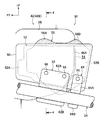
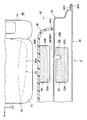
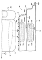
- FIG. 3 is a plan sectional view showing an attachment state of an outer pad and an inner pad used in the front side door shown in FIG. 2.
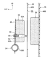
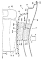
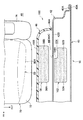
- FIG. 4 is a longitudinal sectional view taken along line 4-4 of FIG. It is a plane sectional view corresponding to Drawing 3 showing the deformation state of the outer pad and inner pad in the front side door at the time of a side collision.
- an arrow FR appropriately shown indicates the vehicle front side
- an arrow UP indicates the vehicle upper side
- an arrow OUT indicates the vehicle width direction outer side.
- FIG. 1 is a side view of a side portion of a vehicle to which the vehicle side door structure according to the present embodiment is applied.
- a front side door opening 12 and a rear side door opening 14 are formed in the vehicle front-rear direction on the side of the body 11 of the vehicle 10.
- a front side door 16 is attached to the front side door opening 12 so as to be opened and closed by a hinge 18, and a rear side door 20 is attached to the rear side door opening 14 so as to be opened and closed by a hinge 22.
- the front side door 16 includes a door outer panel 40 disposed on the outer side in the vehicle width direction, and a door inner panel 42 (see FIG. 3) disposed on the inner side in the vehicle width direction.
- An impact beam 24 is disposed in the front side door 16 along the longitudinal direction of the vehicle body.
- a front end portion 24A of the impact beam 24 is fixed to a front end portion of the door inner panel 42 via a bracket 26. Yes.
- the rear end portion 24B of the impact beam 24 is fixed to the rear end portion of the door inner panel 42 via the bracket 28.
- the vehicle side door structure 50 of the present embodiment is applied to the front side door 16, and an outer pad 52 is attached to the rear end portion 24 ⁇ / b> B side of the impact beam 24 inside the front side door 16.
- the vehicle side door structure 50 will be described in detail later.
- an impact beam 30 is disposed inside the rear side door 20 along the longitudinal direction of the vehicle body.
- the front end portion 30A and the rear end portion 30B of the impact beam 30 are fixed to front and rear end portions of a door inner panel (not shown) via brackets 32 and 34, respectively.
- a door outer pad is attached to the rear end portion 30B side of the impact beam 30.
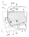
- FIG. 2 shows an enlarged side view of the mounting state of the outer pad and the inner pad of the front side door 16 to which the vehicle side door structure 50 is applied as viewed from the outside in the vehicle width direction.
- 3 shows a plan view of the outer pad and inner pad attached to the front side door 16
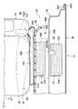
- FIG. 4 shows a vertical sectional view of the outer pad and inner pad attached to the front side door 16.
- FIG. This is shown in the figure (a longitudinal sectional view taken along line 4-4 in FIG. 2).
- the front side door 16 has a closed cross section in which the peripheral portion 40A of the metal door outer panel 40 is integrated with the peripheral portion 42A of the metal door inner panel 42 by hemming. Yes.
- a vertical wall portion 42B that protrudes inward in the vehicle width direction from the peripheral edge portion 42A and is arranged in the vehicle up-down direction and the vehicle front-rear direction is formed at an intermediate portion of the door inner panel 42 in the vehicle front-rear direction.
- a service hole 44 having a substantially oval opening is formed near the center of the vertical wall portion 42B of the door inner panel 42.
- a resin door trim 46 is attached to the inner side in the vehicle width direction of the vertical wall portion 42B of the door inner panel 42 with a clip or the like (not shown).
- the door trim 46 is curved so as to protrude from the end portion 46A in the vehicle front-rear direction to the vehicle width direction inner side (vehicle compartment 48 side), and along the vehicle vertical direction and the vehicle front-rear direction on the vehicle width direction inner side of the curved surface.
- a vertical wall portion 46B is formed.
- an inner pad 56 for absorbing an impact from the side of the vehicle is disposed between the door inner panel 42 and the door trim 46.
- the inner pad 56 is fixed to the outer wall surface (wall surface on the outer side in the vehicle width direction) of the vertical wall portion 46B of the door trim 46 with an adhesive or the like.
- the inner pad 56 is arranged so as to straddle the outer peripheral edge 44 ⁇ / b> A on the vehicle rear side of the service hole 44 in the vehicle front-rear direction when viewed from the side of the vehicle. That is, the front side portion 56A of the inner pad 56 in the vehicle front-rear direction is arranged to face the service hole 44, and the rear side portion 56B of the inner pad 56 in the vehicle front-rear direction is the vertical wall of the door inner panel 42.
- the inner pad 56 is formed of an elastic body such as foamable resin or rubber.
- an outer pad 52 for absorbing an impact from the side surface of the vehicle is disposed, and the outer pad 52 is disposed on the outer side in the vehicle width direction of the inner pad 56 in a side view of the vehicle. They are arranged so as to overlap. That is, the outer pad 52 is formed in a substantially rectangular shape when viewed from the side of the vehicle, and is disposed so as to straddle the outer peripheral edge 44A on the vehicle rear side of the service hole 44 in the vehicle front-rear direction.
- the outer pad 52 is formed of an elastic body such as foamable resin or rubber.
- a groove portion (notch) 54 is formed on the inner side wall surface of the outer pad 52 in the vehicle width direction as a fragile portion that is recessed outward in the vehicle width direction along the outer peripheral edge 44A of the service hole 44 on the vehicle rear side.
- the outer pad 52 includes a front side portion (first portion) 52A disposed to face the service hole 44 on the vehicle front side from the groove portion 54, and a vertical wall portion 42B of the door inner panel 42 on the vehicle rear side from the groove portion 54. And a rear side portion (second portion) 52B arranged so as to face each other (see FIGS. 2 and 3).
- the outer side wall surface of the outer pad 52 in the vehicle width direction is fixed to the resin plate 60 with an adhesive or the like.
- the resin plate 60 is formed in a substantially rectangular shape when viewed from the side of the vehicle, and is formed slightly larger than the outer shape of the outer pad 52.
- the resin plate 60 is attached to the impact beam 24 by two brackets 62 and 64 disposed on the front and rear of the vehicle (see FIG. 2). More specifically, the bracket 62 fixes a portion corresponding to the front portion 52A of the outer pad 52 in the resin plate 60, and the bracket 64 corresponds to the rear portion 52B of the outer pad 52 in the resin plate 60. The part is fixed.
- the bracket 62 includes a planar mounting portion 62A disposed in surface contact with the resin plate 60, and a concave portion 62B formed on the lower side of the mounting portion 62A (see FIG. 4).
- the impact beam 24 is a pipe-shaped member having a predetermined strength and rigidity.
- the concave portion 62B of the bracket 62 is formed in a substantially semicircular shape so as to protrude inward in the vehicle width direction, and the concave portion 62B is disposed so as to contact the peripheral surface of the impact beam 24. They are joined by arc welding (see FIGS. 2 and 4).
- the mounting portion 62A is disposed in surface contact with the resin plate 60, and the mounting portion 62A and the resin plate 60 are fastened and fixed by bolts 66 and nuts 68 from both sides thereof.
- the nut 68 may be fixed to the resin plate 60 in advance, and the bolt 66 may be inserted from the attachment portion 62A side and screwed.
- the mounting portion 62A and the resin plate 60 are fastened and fixed by two sets of bolts 66 and nuts 68 before and after the vehicle, so that the resin plate 60 corresponding to the front portion 52A is fixed to the impact beam 24 via the bracket 62. Yes.
- the bracket 64 is formed with a shorter width in the vehicle longitudinal direction than the bracket 62.
- the bracket 64 includes a flat mounting portion 64A disposed in surface contact with the resin plate 60, and a concave portion 64B formed on the lower side of the mounting portion 64A.
- the concave portion 64B is formed in a substantially semicircular shape so as to protrude inward in the vehicle width direction when viewed from the rear of the vehicle, and is disposed so that the concave portion 64B contacts the peripheral surface of the impact beam 24 and is arc-welded. They are joined (see FIG. 2).
- the mounting portion 64A is disposed in surface contact with the resin plate 60, and the mounting portion 64A and the resin plate 60 are fastened and fixed from both sides by a pair of bolts 66 and nuts (not shown). Thereby, the resin plate 60 corresponding to the rear side portion 52 ⁇ / b> B is fixed to the impact beam 24 through the bracket 64. In a state where the outer pad 52 bonded to the resin plate 60 is fixed to the impact beam 24 via the brackets 62 and 64, the outer pad 52 is positioned between the outer surface in the vehicle width direction and the inner surface in the vehicle width direction of the door outer panel 40. A gap is formed in (see FIG. 3).
- the outer pad 52 Since the groove 54 is formed on the wall surface of the outer pad 52 along the outer peripheral edge 44A of the service hole 44, the outer pad 52 is brought into contact with the door inner panel 42 as the door outer panel 40 enters during a side collision as shown in FIG. In the vicinity of the outer peripheral edge 44A of the service hole 44, the outer pad 52 breaks into a front part (first part) 52A and a rear part (second part) 52B starting from the groove 54. As a result, the outer pad 52 is divided into a front part 52A and a rear part 52B and moves inward in the vehicle width direction. The front part 52A passes through the service hole 44 and pushes the inner pad 56 toward the door trim 46. The part 52 ⁇ / b> B pushes the inner pad 56 toward the door trim 46 through the door inner panel 42.
- the resin plate 60 is formed with weak portions such as notches and a plurality of cuts (folded lines) along the groove 54 (the outer peripheral edge 44A of the service hole 44).
- the front side part 52A and the rear side part 52B move independently because the outer pad 52 hits the door inner panel 42 and the resin plate 60 is broken at the fragile part as the door outer panel 40 enters during a side collision. Is allowed.
- a notch is provided on the resin plate 60 above the bracket 64 on the resin plate 60 and on the vehicle rear side of the outer peripheral edge 44A of the service hole 44. It is good also as a structure which is easy to break along 44A.
- the resin plate 60 is one component, it may be comprised by two components and you may arrange
- the outer pad 52 is connected to the front side portion 52A and the rear side portion.
- the front side portion 52A and the rear side portion 52B are not separated from the impact beam 24 after being broken into 52B.
- a front seat 70 as a vehicle seat is disposed inside the vehicle compartment 48 inside the front side door 16 in the vehicle width direction.
- the front seat 70 is provided at a position facing the front side door opening 12 of the passenger compartment 48.
- the front seat 70 is provided along the vertical direction at the rear end of the seat cushion 72 in the vehicle longitudinal direction of the seat cushion 72 that supports the buttocks and thighs of the seated passenger 80 and supports the back of the passenger.
- the outer pad 52 and the inner pad 56 are provided at positions corresponding to the waist 80A of the occupant 80 seated on the front seat 70 along the vehicle width direction.
- the outer pad 52 becomes the outer peripheral edge of the service hole 44 in the door inner panel 42 as the door outer panel 40 enters.
- the outer pad 52 breaks into a front side part (first part) 52A and a rear side part (second part) 52B with the groove 54 as a starting point.
- the outer pad 52 is divided
- the front part 52A of the outer pad 52 passes through the service hole 44 and directly pushes the inner pad 56 toward the door trim 46, and the rear part 52B of the outer pad 52 passes through the door inner panel 42. Then, the inner pad 56 is pushed into the door trim 46 side.
- the outer pad may be caught on the door inner panel 42, and the front portion facing the service hole 44 may not be able to press the inner pad 56 at an early stage.
- the front side portion 52A and the rear side portion 52B are broken, so that the front side portion 52A can push the inner pad 56 at an early stage.
- the waist 80A of the occupant 80 seated on the front seat 70 at the time of a side collision can be pushed quickly over a wide area. More specifically, the front side portion 52A of the outer pad 52 pushes the inner pad 56 inward in the vehicle width direction, thereby quickly pushing the waist 80A of the occupant 80 seated on the front seat 70 and increasing the initial restraining force.
- the rear side portion 52B of the outer pad 52 pushes the inner pad 56 inward in the vehicle width direction through the door inner panel 42, so that the restraining area of the waist 80A of the occupant 80 seated on the front seat 70 can be expanded. .
- the front side portion 52A and the rear side portion 52B of the outer pad 52 are attached to the impact beam 24 by separate brackets 62 and 64. Thereby, even if the outer pad 52 breaks into the front side part 52A and the rear side part 52B at the time of a side collision, the front side part 52A and the rear side part 52B are supported without being separated by the impact beam 24. The input to the waist 80A of the occupant 80 seated on the seat 70 is stabilized.
- a metal (for example, iron) plate material is disposed inside the rear side portion 52 ⁇ / b> B of the outer pad 92 that faces the vertical wall portion 42 ⁇ / b> B of the door inner panel 42.
- 94 is embedded.
- a front end 94A of the plate member 94 in the vehicle front-rear direction is disposed along the outer peripheral edge 44A of the service hole 44 in a vehicle side view.
- a boundary portion between the front end 94A of the plate member 94 in the rear side portion 52B of the outer pad 92 and the front side portion 52A in which the plate member 94 is not embedded is set as a fragile portion that becomes a starting point of breakage at the time of a side collision.
- the rear portion 52B of the outer pad 92 hits the vicinity of the outer peripheral edge 44A of the service hole 44 in the door inner panel 42 as the door outer panel 40 enters during a side collision, so that the boundary portion between the front end 94A of the plate 94 and the front portion 52A.
- the outer pad 92 is broken into a front side portion 52A and a rear side portion 52B.
- the front part 52A of the outer pad 92 pushes the inner pad 56 inward in the vehicle width direction through the service hole 44, and the rear part 52B of the outer pad 92 passes the inner pad 56 through the door inner panel 42 in the vehicle width direction. Push inward.
- a metal plate 94 is embedded in the rear side portion 52B of the outer pad 92, and the rear side portion 52B is made to be more rigid than the front side portion 52A, so that the inner side is stronger through the door inner panel 42 at the time of a side collision.
- the pad 56 can be pressed toward the door trim 46 side.
- a metal plate 94 is embedded in the rear portion 52B of the outer pad 92.
- a metal plate is embedded in the front portion 52A of the outer pad 92.
- the rear end of the plate material may be disposed along the outer peripheral edge 44A of the service hole 44 in a vehicle side view.
- a notch 104 is formed.
- the front end 104 ⁇ / b> A of the notch 104 is disposed along the outer peripheral edge 44 ⁇ / b> A of the service hole 44 in a vehicle side view.
- the front end 104A of the notch 104 in the rear portion 52B of the outer pad 102 hits the outer peripheral edge 44A of the service hole 44 in the door inner panel 42 as the door outer panel 40 enters during a side collision
- the front end 104A of the notch 104 The outer pad 102 breaks into a front side portion 52A and a rear side portion 52B starting from the vicinity. Accordingly, the front side portion 52A of the outer pad 102 pushes the inner pad 56 inward in the vehicle width direction through the service hole 44, and the rear side portion 52B of the outer pad 102 passes the inner pad 56 through the door inner panel 42 in the vehicle width direction. Push inward. For this reason, the waist part 80A of the occupant 80 seated on the front seat 70 can be pushed early in a wide area.
- the fragile portion that becomes the starting point of the breakage of the front portion 52A and the rear portion 52B of the outer pad at the time of a side collision is limited to the vehicle side door structures 50, 90, 100 of the first to third embodiments.
- other configurations are possible.
- a configuration in which a plurality of cuts are formed in the outer pad along the outer peripheral edge 44A of the service hole 44, or a configuration in which a hollow hole is provided in the outer pad along the outer peripheral edge 44A of the service hole 44 may be employed. That is, the outer pad may be configured to have a difference in strength along the outer peripheral edge 44 ⁇ / b> A of the service hole 44.
- the front side portion 52A and the rear side portion 52B of the outer pads 52, 92, 102 are formed of an elastic body having the same hardness, for example, by foaming resin or the like.
- the present invention is not limited to this, and the rear side portion 52B facing the vertical wall portion 42B of the door inner panel 42 may be configured to be harder than the front side portion 52A facing the service hole 44.
- the rear side portion 52B is hardened by lowering the foaming rate of the rear side portion 52B facing the vertical wall portion 42B of the door inner panel 42 than the foaming rate of the front side portion 52A facing the service hole 44. Can do.
- the rear side part 52B can be made harder than the front side part 52A by changing the cross-sectional shape of the outer pad (for example, a hollow cross section or a U-shaped cross section). With this configuration, the rear portion 52B can push the inner pad 56 more strongly through the vertical wall portion 42B of the door inner panel 42 at the time of a side collision.
- FIG. 8 shows a side view of the mounting state of the outer pad 122 used in the front side door to which the vehicle side door structure 120 is applied as viewed from the inside in the vehicle width direction.
- the outer pad 122 includes a front side portion (first portion) 122A that faces the service hole 44 in advance along the outer peripheral edge 44A of the service hole 44 on the vehicle rear side, and a door inner panel 42. It is divided into a rear side portion (second portion) 122B facing the vertical wall portion 42B.
- the front portion 122A and the rear portion 122B are fixed to the resin plate 60 with an adhesive or the like in a state where a gap is formed between the rear end surface of the front portion 122A and the front end surface of the rear portion 122B. .
- the resin plate 60 is formed with a weak portion such as a notch or a plurality of cuts (a broken line) along the outer peripheral edge 44A of the service hole 44. By cracking as a starting point, the front side portion 122A and the rear side portion 122B are allowed to move independently.
- the front side portion 122A and the rear side portion 122B of the outer pad 122 are formed of an elastic body made of foamable resin or rubber, and the rear side portion 122B is harder than the front side portion 122A.
- the rear side portion 122B is hardened by making the foaming rate of the rear side portion 122B lower than the foaming rate of the front side portion 122A.
- the outer pad 122 is divided in advance into a front side portion 122A and a rear side portion 122B, and the resin plate 60 accompanies the door outer panel 40 (see FIG. 3) when a side collision occurs.
- the front portion 122A and the rear portion 122B independently move inward in the vehicle width direction. That is, as the door outer panel 40 enters, the front portion 122A passes through the service hole 44 and pushes the inner pad 56 (see FIG. 3) inward in the vehicle width direction, and the rear portion 122B is the vertical wall portion of the door inner panel 42.
- the inner pad 56 is pushed inward in the vehicle width direction through 42B. Thereby, the waist part of the passenger
- the outer pad 122 is configured such that the rear portion 122B is harder than the front portion 122A, and the rear portion 122B strengthens the inner pad 56 via the vertical wall portion 42B of the door inner panel 42 at the time of a side collision. Can be pressed.
- the rear side portion 122B is made harder by lowering the foaming rate of the rear side portion 122B than the foaming rate of the front side portion 122A.
- the present invention is not limited to this.
- the cross-sectional shape of the side portion 122B for example, by changing the hollow cross-section, changing the thickness in the vehicle width direction
- the rear side of the front side portion 122A The structure which makes the part 122B hard or highly rigid may be sufficient.
- FIG. 9 is a plan sectional view showing the configuration near the front side door 16 to which the occupant protection system 150 is applied.
- a side airbag device 152 is mounted on the outer side in the vehicle width direction of a seat back 74 constituting a part of a front seat (vehicle seat) 70. ing.
- a side collision state is detected by a side collision sensor (not shown), and energized by a controller (not shown).
- An inflator (not shown) that generates a large amount of gas and jets the gas into the side airbag 154 is provided.
- the side airbag device 152 when a large acceleration greater than or equal to a predetermined value is applied to the vehicle due to a side collision, this state is detected by the side collision sensor, and a predetermined current is supplied from the controller to the ignition device of the inflator. As a result, the inflator is activated, a large amount of gas is generated, the side surface of the seat back 74 is opened, and the side airbag 154 is inflated and deployed. That is, the side airbag 154 is inflated and deployed between the door trim 46 and the occupant 80 seated on the front seat 70, thereby absorbing kinetic energy and protecting the occupant.
- the side airbag 154 when the side airbag 154 is inflated and deployed between the door trim 46 and the occupant 80 seated on the front seat 70 at the time of a side collision, the side airbag 154 has both sides in the vehicle width direction. The surface hits the waist 80A of the occupant 80 and the door trim 46. As a result, the side airbag 154 pushes the door trim 46 outward in the vehicle width direction, and is input from the end 46A of the door trim 46 to the door inner panel 42 as indicated by the arrow B.
- the outer pad 52 breaks into the front side portion 52A and the rear side portion 52B with the groove portion 54 as a starting point.
- the front portion 52A and the rear portion 52B can move independently in the vehicle width direction as the door outer panel 40 enters.
- the outer pad 52 can be divided by inflating and deploying the side airbag 154 before the outer pad 52 is divided by the intrusion of the door outer panel 40. Can be pressed.
- the side airbag device 152 is provided on the side portion of the seat back 74 on the outer side in the vehicle width direction. Instead, this is indicated by a two-dot chain line in FIG.
- the side airbag device 170 may be provided on the door inner panel 42 side at the rear portion in the door trim 46 so that the side airbag is inflated and deployed by opening the door trim 46 at the time of a side collision. Even in this configuration, the inflated side airbag hits the waist 80A of the occupant 80 seated on the front seat 70 and the door trim 46, so that the outer pad 52 starts from the groove 54 using the input to the door inner panel 42.
- the front part 52A and the rear part 52B can be broken.
- the outer pad is disposed on the outer peripheral edge 44A on the rear side of the service hole 44 so as to straddle the vehicle front-rear direction, so as to face the service hole 44.
- (First part) and a rear part (second part) facing the door inner panel 42 are provided, but the present invention is not limited to this configuration.
- the outer pad is disposed on the outer peripheral edge 44A on the front side of the service hole 44 so as to straddle the vehicle front-rear direction, so that the rear side part (first part) facing the service hole 44, the door inner panel,
- part) which opposes may be sufficient.
- the rear part (first part) passes through the service hole 44 and pushes the inner pad to the door trim side, and the front part (second part) is separated from the rear part and passes through the door inner panel.
- the inner pad may be pushed toward the door trim.
- the vehicle side door structure 50 according to the present invention is applied to the front side door 16, but the present invention is not limited to this.
- the vehicle side door structure 50 according to the fifth embodiment may be applied.
Landscapes
- Engineering & Computer Science (AREA)
- Mechanical Engineering (AREA)
- Air Bags (AREA)
- Body Structure For Vehicles (AREA)
Abstract
Description
また、本実施形態では、樹脂プレート60は一部品であるが、2部品で構成し、前方側部位52Aに対応する位置と後方側部位52Bに対応する位置とに配置してもよい。
また、アウタパッド92の後方側部位52Bに金属製の板材94を埋設し、後方側部位52Bを前方側部位52Aよりも高剛性とすることで、側面衝突時にドアインナパネル42を介してより強くインナパッド56をドアトリム46側に押圧することができる。
このサイドエアバック装置152では、側面衝突により車両に所定値以上の大きな加速度が加わると、この状態が側面衝突センサによって検出され、コントローラからインフレータの点火装置に所定の電流が通電される。これにより、インフレータが作動し、大量のガスを発生し、シートバック74の側面が開いてサイドエアバック154を膨張展開させる。すなわち、サイドエアバック154をドアトリム46と前席シート70に着座した乗員80との間に膨張展開させることで、運動エネルギーを吸収し、乗員を保護するようになっている。
Claims (8)
- 車両幅方向外側に配置されるドアアウタパネルと、
車両幅方向内側に配置され、前記ドアアウタパネルとで袋状に形成されると共に、車両前後方向の中間部にサービスホールが形成されたドアインナパネルと、
前記ドアインナパネルの車両幅方向内側に取り付けられるドアトリムと、
前記ドアインナパネルと前記ドアトリムとの間に配置されると共に、車両側面視にて前記サービスホールの外周縁に車両前後方向に跨るように設けられ、車両側面からの衝撃を吸収するインナパッドと、
前記ドアアウタパネルと前記ドアインナパネルとの間に配置されると共に、車両側面視にて前記インナパッドの車両幅方向外側に重なるように設けられ、かつ、側面衝突時に前記ドアアウタパネルに押されて前記サービスホールを通って前記インナパッドを前記ドアトリム側へ押す第1の部位と、側面衝突時に前記第1の部位と分かれて前記ドアインナパネルを介して前記インナパッドを前記ドアトリム側へ押す第2の部位と、を備えたアウタパッドと、
を有する車両用サイドドア構造。 - 前記アウタパッドには、前記サービスホールの外周縁に沿って側面衝突時に前記第1の部位と前記第2の部位との破断の起点となるように脆弱部が設けられている請求項1に記載の車両用サイドドア構造。
- 前記ドアアウタパネルと前記ドアインナパネルとの間に車両前後方向に沿ってインパクトビームが延在されており、
前記アウタパッドにおける前記第1の部位と前記第2の部位とは、別個のブラケットにより前記インパクトビームに取り付けられている請求項1又は請求項2に記載の車両用サイドドア構造。 - 前記アウタパッドは、前記第2の部位が前記第1の部位よりも硬く又は高剛性に構成されている請求項1から請求項3までのいずれか1項に記載の車両用サイドドア構造。
- 前記アウタパッドは、前記サービスホールの外周縁に沿って前記第1の部位と前記第2の部位に予め分割されている請求項1に記載の車両用サイドドア構造。
- 前記ドアアウタパネルと前記ドアインナパネルとの間に車両前後方向に沿ってインパクトビームが延在されており、
前記アウタパッドにおける前記第1の部位と前記第2の部位とは、別個のブラケットにより前記インパクトビームに取り付けられている請求項5に記載の車両用サイドドア構造。 - 前記アウタパッドは、前記第2の部位が前記第1の部位よりも硬く又は高剛性に構成されている請求項5又は請求項6に記載の車両用サイドドア構造。
- 請求項2から請求項4までのいずれか1項に記載の車両用サイドドア構造を備え、
側面衝突時に車両用シートに着座した乗員の腰部と前記ドアトリムとの間にサイドエアバックが膨張展開するサイドエアバック装置が前記車両用シートの一部を構成するシートバックの側部、又は前記ドアトリムの内部に設けられている乗員保護システム。
Priority Applications (5)
| Application Number | Priority Date | Filing Date | Title |
|---|---|---|---|
| EP11874900.1A EP2774792A4 (en) | 2011-11-02 | 2011-11-02 | SIDE DOOR STRUCTURE OF A VEHICLE AND VEHICLE ABSORPTION SYSTEM |
| CN201180074542.8A CN103906640A (zh) | 2011-11-02 | 2011-11-02 | 车辆用侧门结构以及乘员保护系统 |
| JP2013541550A JP5590250B2 (ja) | 2011-11-02 | 2011-11-02 | 車両用サイドドア構造及び乗員保護システム |
| PCT/JP2011/075342 WO2013065158A1 (ja) | 2011-11-02 | 2011-11-02 | 車両用サイドドア構造及び乗員保護システム |
| US14/344,992 US9004529B2 (en) | 2011-11-02 | 2011-11-02 | Vehicle side door structure and passenger protecting system |
Applications Claiming Priority (1)
| Application Number | Priority Date | Filing Date | Title |
|---|---|---|---|
| PCT/JP2011/075342 WO2013065158A1 (ja) | 2011-11-02 | 2011-11-02 | 車両用サイドドア構造及び乗員保護システム |
Publications (1)
| Publication Number | Publication Date |
|---|---|
| WO2013065158A1 true WO2013065158A1 (ja) | 2013-05-10 |
Family
ID=48191549
Family Applications (1)
| Application Number | Title | Priority Date | Filing Date |
|---|---|---|---|
| PCT/JP2011/075342 Ceased WO2013065158A1 (ja) | 2011-11-02 | 2011-11-02 | 車両用サイドドア構造及び乗員保護システム |
Country Status (5)
| Country | Link |
|---|---|
| US (1) | US9004529B2 (ja) |
| EP (1) | EP2774792A4 (ja) |
| JP (1) | JP5590250B2 (ja) |
| CN (1) | CN103906640A (ja) |
| WO (1) | WO2013065158A1 (ja) |
Cited By (2)
| Publication number | Priority date | Publication date | Assignee | Title |
|---|---|---|---|---|
| US20150251617A1 (en) * | 2014-03-05 | 2015-09-10 | Toyota Motor Engineering & Manufacturing North America, Inc. | Morphing energy absorber system for a vehicle assembly |
| JP2023112289A (ja) * | 2022-02-01 | 2023-08-14 | ダイハツ工業株式会社 | 車両構造 |
Families Citing this family (9)
| Publication number | Priority date | Publication date | Assignee | Title |
|---|---|---|---|---|
| JP6525201B2 (ja) * | 2015-09-18 | 2019-06-05 | トヨタ紡織株式会社 | ドアトリム及び車両用ドア |
| JP6409747B2 (ja) * | 2015-11-16 | 2018-10-24 | トヨタ自動車株式会社 | 車両用サイドドア構造 |
| US10029735B2 (en) * | 2016-01-29 | 2018-07-24 | Nissan North America, Inc. | Vehicle body structure |
| KR101896325B1 (ko) | 2016-11-15 | 2018-09-07 | 현대자동차 주식회사 | 차량용 cfrp 도어의 임팩트 빔 구조 |
| KR102621230B1 (ko) * | 2019-01-24 | 2024-01-05 | 현대자동차 주식회사 | 차량용 도어 |
| US11130392B2 (en) | 2019-05-20 | 2021-09-28 | Toyota Motor Engineering & Manufacturing North America, Inc. | Door service hole cover |
| US11065945B2 (en) * | 2019-06-05 | 2021-07-20 | Nissan North America, Inc. | Vehicle door structure |
| US11505042B2 (en) * | 2020-03-11 | 2022-11-22 | Fca Us Llc | Vehicle having reinforcement patch |
| US20230173896A1 (en) * | 2020-06-30 | 2023-06-08 | Toray Industries, Inc. | Impact absorbing structure |
Citations (6)
| Publication number | Priority date | Publication date | Assignee | Title |
|---|---|---|---|---|
| JPS53147323A (en) * | 1977-05-27 | 1978-12-22 | Daimler Benz Ag | Side frame protector of automobile |
| JPH07232554A (ja) | 1994-02-25 | 1995-09-05 | Nissan Motor Co Ltd | 車両のドア構造 |
| JP2005138838A (ja) | 2005-01-17 | 2005-06-02 | Mazda Motor Corp | 自動車の衝撃吸収パッド取付構造 |
| JP2008094235A (ja) * | 2006-10-11 | 2008-04-24 | Toyota Motor Corp | 車両用乗員保護装置 |
| JP2008254635A (ja) | 2007-04-06 | 2008-10-23 | Nissan Motor Co Ltd | 衝撃吸収部材の取付構造および取付方法 |
| JP2011513136A (ja) * | 2008-03-06 | 2011-04-28 | 本田技研工業株式会社 | 乗用車ドア用2点保護パッド |
Family Cites Families (11)
| Publication number | Priority date | Publication date | Assignee | Title |
|---|---|---|---|---|
| US5395135A (en) * | 1992-11-02 | 1995-03-07 | Ford Motor Company | Energy absorbing vehicle door and side panels |
| JP3521452B2 (ja) * | 1992-11-09 | 2004-04-19 | マツダ株式会社 | 自動車のドア構造 |
| US5542738A (en) * | 1994-12-23 | 1996-08-06 | Ford Motor Company | Energy absorbing vehicle door with guard beam load distributor |
| JP4360050B2 (ja) * | 2001-06-11 | 2009-11-11 | 三菱自動車工業株式会社 | 衝撃吸収装置 |
| JP3950356B2 (ja) * | 2002-03-29 | 2007-08-01 | 本田技研工業株式会社 | サイドエアバッグ装置 |
| US6955391B1 (en) * | 2003-01-14 | 2005-10-18 | Ford Global Technologies, Llc | Deployable trim for side impact system in automobiles |
| JP4857825B2 (ja) * | 2005-05-31 | 2012-01-18 | 豊田合成株式会社 | 乗員の保護方法及び保護構造 |
| US7341277B2 (en) * | 2005-07-13 | 2008-03-11 | Honda Motor Co., Ltd. | Occupant safety device |
| US7357444B2 (en) * | 2006-03-06 | 2008-04-15 | International Automotive Components Group North America, Inc. | Tunable geometry for energy absorbing foam to lower peak load during side impact |
| EP2082909A1 (en) * | 2008-01-23 | 2009-07-29 | Mazda Motor Corporation | Side impact absorbing structure for vehicle |
| US8152218B2 (en) * | 2008-05-13 | 2012-04-10 | Ford Global Technologies, Llc | Integral pelvic impact energy-absorbing pre-crush protective construction for vehicle door |
-
2011
- 2011-11-02 WO PCT/JP2011/075342 patent/WO2013065158A1/ja not_active Ceased
- 2011-11-02 JP JP2013541550A patent/JP5590250B2/ja not_active Expired - Fee Related
- 2011-11-02 EP EP11874900.1A patent/EP2774792A4/en not_active Withdrawn
- 2011-11-02 US US14/344,992 patent/US9004529B2/en not_active Expired - Fee Related
- 2011-11-02 CN CN201180074542.8A patent/CN103906640A/zh active Pending
Patent Citations (6)
| Publication number | Priority date | Publication date | Assignee | Title |
|---|---|---|---|---|
| JPS53147323A (en) * | 1977-05-27 | 1978-12-22 | Daimler Benz Ag | Side frame protector of automobile |
| JPH07232554A (ja) | 1994-02-25 | 1995-09-05 | Nissan Motor Co Ltd | 車両のドア構造 |
| JP2005138838A (ja) | 2005-01-17 | 2005-06-02 | Mazda Motor Corp | 自動車の衝撃吸収パッド取付構造 |
| JP2008094235A (ja) * | 2006-10-11 | 2008-04-24 | Toyota Motor Corp | 車両用乗員保護装置 |
| JP2008254635A (ja) | 2007-04-06 | 2008-10-23 | Nissan Motor Co Ltd | 衝撃吸収部材の取付構造および取付方法 |
| JP2011513136A (ja) * | 2008-03-06 | 2011-04-28 | 本田技研工業株式会社 | 乗用車ドア用2点保護パッド |
Non-Patent Citations (1)
| Title |
|---|
| See also references of EP2774792A4 |
Cited By (3)
| Publication number | Priority date | Publication date | Assignee | Title |
|---|---|---|---|---|
| US20150251617A1 (en) * | 2014-03-05 | 2015-09-10 | Toyota Motor Engineering & Manufacturing North America, Inc. | Morphing energy absorber system for a vehicle assembly |
| JP2023112289A (ja) * | 2022-02-01 | 2023-08-14 | ダイハツ工業株式会社 | 車両構造 |
| JP7761192B2 (ja) | 2022-02-01 | 2025-10-28 | ダイハツ工業株式会社 | 車両構造 |
Also Published As
| Publication number | Publication date |
|---|---|
| CN103906640A (zh) | 2014-07-02 |
| US20140367947A1 (en) | 2014-12-18 |
| US9004529B2 (en) | 2015-04-14 |
| JPWO2013065158A1 (ja) | 2015-04-02 |
| EP2774792A4 (en) | 2014-10-15 |
| EP2774792A1 (en) | 2014-09-10 |
| JP5590250B2 (ja) | 2014-09-17 |
Similar Documents
| Publication | Publication Date | Title |
|---|---|---|
| JP5590250B2 (ja) | 車両用サイドドア構造及び乗員保護システム | |
| CN104024059B (zh) | 汽车用安全气囊系统 | |
| EP2699454B1 (en) | Unification airbag module | |
| KR101916007B1 (ko) | 파-사이드 에어백 | |
| EP3616981B1 (en) | Vehicle seat | |
| KR101283698B1 (ko) | 차량의 사이드 에어백 | |
| WO2012111073A1 (ja) | 乗員保護装置 | |
| WO2013054397A1 (ja) | 車両用ニーエアバッグ装置 | |
| WO2010050019A1 (ja) | 車両用ニーエアバッグ装置 | |
| WO2000050270A1 (en) | Inflatable protection apparatus | |
| JP2017149331A (ja) | 車両構造 | |
| EP1481857A1 (en) | Occupant knee part protective device for vehicle | |
| JP2014076762A (ja) | エアバッグドアを一体に有するインストルメントパネル | |
| JP2014015087A (ja) | カーテンエアバッグ装置のジャンプ台取付構造 | |
| KR101250413B1 (ko) | 통합형 에어백 모듈 | |
| JP7801621B2 (ja) | 乗物用シート | |
| JP2014141194A (ja) | 膝側面拘束用エアバッグ装置 | |
| JP2007223525A (ja) | 乗員保護装置 | |
| JP2009248610A (ja) | エアバッグドア支持構造 | |
| JP4529325B2 (ja) | 車両乗員保護装置 | |
| JP6803910B2 (ja) | 車両用エアバッグ装置、及びエアバッグ装置のエアバッグクッション | |
| JP4585145B2 (ja) | エアバッグドアの跳返り防止構造 | |
| JP2019031132A (ja) | 乗物用シート | |
| WO2006095803A1 (ja) | エアバッグ装置 | |
| JP5725046B2 (ja) | 膝側面拘束用エアバッグ装置 |
Legal Events
| Date | Code | Title | Description |
|---|---|---|---|
| 121 | Ep: the epo has been informed by wipo that ep was designated in this application |
Ref document number: 11874900 Country of ref document: EP Kind code of ref document: A1 |
|
| DPE2 | Request for preliminary examination filed before expiration of 19th month from priority date (pct application filed from 20040101) | ||
| ENP | Entry into the national phase |
Ref document number: 2013541550 Country of ref document: JP Kind code of ref document: A |
|
| WWE | Wipo information: entry into national phase |
Ref document number: 14344992 Country of ref document: US |
|
| WWE | Wipo information: entry into national phase |
Ref document number: 2011874900 Country of ref document: EP |
|
| NENP | Non-entry into the national phase |
Ref country code: DE |