WO2013065176A1 - ヘルメット - Google Patents
ヘルメット Download PDFInfo
- Publication number
- WO2013065176A1 WO2013065176A1 PCT/JP2011/075462 JP2011075462W WO2013065176A1 WO 2013065176 A1 WO2013065176 A1 WO 2013065176A1 JP 2011075462 W JP2011075462 W JP 2011075462W WO 2013065176 A1 WO2013065176 A1 WO 2013065176A1
- Authority
- WO
- WIPO (PCT)
- Prior art keywords
- cheek
- air
- helmet
- cover
- edge
- Prior art date
- Legal status (The legal status is an assumption and is not a legal conclusion. Google has not performed a legal analysis and makes no representation as to the accuracy of the status listed.)
- Ceased
Links
Images


Classifications
-
- A—HUMAN NECESSITIES
- A42—HEADWEAR
- A42B—HATS; HEAD COVERINGS
- A42B3/00—Helmets; Helmet covers ; Other protective head coverings
- A42B3/04—Parts, details or accessories of helmets
- A42B3/10—Linings
- A42B3/12—Cushioning devices
- A42B3/125—Cushioning devices with a padded structure, e.g. foam
-
- A—HUMAN NECESSITIES
- A42—HEADWEAR
- A42B—HATS; HEAD COVERINGS
- A42B3/00—Helmets; Helmet covers ; Other protective head coverings
- A42B3/04—Parts, details or accessories of helmets
- A42B3/28—Ventilating arrangements
- A42B3/281—Air ducting systems
-
- A—HUMAN NECESSITIES
- A42—HEADWEAR
- A42B—HATS; HEAD COVERINGS
- A42B3/00—Helmets; Helmet covers ; Other protective head coverings
- A42B3/04—Parts, details or accessories of helmets
- A42B3/10—Linings
- A42B3/12—Cushioning devices
- A42B3/125—Cushioning devices with a padded structure, e.g. foam
- A42B3/127—Cushioning devices with a padded structure, e.g. foam with removable or adjustable pads
Definitions
- the present invention relates to a helmet to be worn when riding a motorcycle.
- a helmet to be worn when riding a motorcycle or the like includes a cap shell and a shock absorbing member disposed along the inner surface of the cap shell, and the cap shell has a pair of left and right cheek covers, There is one in which a side border member is attached to the lower end edge of the cheek covering part.
- air intake holes are provided in the left and right cheek covers of the cap shell, and the inside of the helmet is taken out of the air extraction holes to ventilate the helmet (for example, Patent Documents). 1).
- an object of the present invention is to provide a helmet that can be ventilated without reducing the strength of the cap shell.
- the technical means of the present invention for solving this technical problem includes a cap shell 3 and an impact absorbing member 4 disposed along the inner surface of the cap shell 3, and the cap shell 3 is a pair of left and right cheek covers.
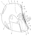
- a notch recess 50 cut upward is provided on the lower end side of the left and right cheek cover parts 9, and the lower edge 9a of the left and right cheek cover parts 9 is inclined upward from the front and rear sides toward the front and rear center.
- a wide portion 52 is formed in the side edge member 22 so as to bulge upward in a mountain shape corresponding to the notch recess 50 and widen up and down, and an air extraction hole 55 is provided in the wide portion 52. There is in point.
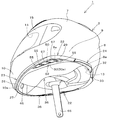
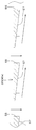
- the side edge member 22 includes a side fitting portion 29 having a U-shaped cross section that fits to the lower end edge 9 a of the cheek covering portion 9, and a side fitting portion 29.
- the side bent edge portion 30 protrudes from the lower end of the side portion, and the portion corresponding to the wide portion 52 of the side fitting portion 29 extends from the front and rear sides along the lower end edge 9a of the cheek covering portion 9 from the front and rear sides.
- a portion that corresponds to the wide portion 52 of the side bent edge 30 is wide and is bent downward from the side fitting portion 29 so as to incline upward toward the top.
- the air extraction hole 55 is formed in the wide bent edge 30a.
- the outer edge of the side edge member 22 is inclined so as to gradually go to the left and right as it goes rearward from the rear opening edge of the air extraction hole 55 or the air extraction hole 55.
- An outside air guide surface 57 is formed so as to gradually go inward from side to side as it goes forward from the front opening edge.
- a plurality of the air extraction holes 55 are provided in the wide portion 52 of the side edge member 22 at intervals in the front-rear direction, and the outside air guide surface 57 is It is arrange
- the cap shell 3 has a chin covering portion 10 that protrudes forward from the lower side of the left and right cheek covering portions 9 and covers the mouth from the chin.
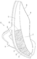
- an air passage 44 is formed inside the cheek covering portion 9 to allow the exhaled air to flow backward toward the air outlet hole 55.
- the shock absorbing member 4 located on the front side of the helmet wearer's mouth is provided with a mouth communication hole 46 communicating with the front portion of the air passage 44. .
- the lower end side of the shock absorbing member 4 corresponding to the cheek covering portion 9 is protruded downward from the lower end edge 9a of the cheek covering portion 9 corresponding to the notch recess 50.
- the side edge member 22 extends to the left and right inner sides of the wide portion 52, and the rear lower side of the air passage 44 is located on the left and right inner sides of the wide portion 52 of the side edge member 22, and the air extraction of the side edge member 22 is performed. It exists in the point connected to the hole 55.
- Another technical means of the present invention is to provide a passage forming groove in the front-rear direction that is immersed inward in the left-right direction on the outer surface of the shock absorbing member 4 corresponding to the chin cover 10 and the cheek cover 9.
- the air passage 44 is formed between the chin cover 10 and the cheek cover 9 and the shock absorbing member 4 corresponding thereto.
- Another technical means of the present invention is that the shock absorbing member 4 corresponding to the chin cover portion 10 and the cheek cover portion 9 is formed with an inside air communication hole 47 communicating from the inner surface to the air passage 44. is there.
- a pair of left and right cheek pads 36 are provided inside the impact absorbing member 4 corresponding to the chin cover 10 and the cheek cover 9, A pad communication hole 58 that communicates with the inside air communication hole 47 is formed so as to penetrate inside and outside. Further, according to another technical means of the present invention, a pair of left and right cheek pads 36 are provided inside the impact absorbing member 4 corresponding to the chin cover 10 and the cheek cover 9, An insertion locking piece 41 is provided that is folded upward from the outer end side in the left-right direction at the lower end portion of the cheek pad 36, and the insertion locking piece 41 passes through the left and right inner sides of the side edge member 22 to cover the chin cover 10.
- the cheek pad 36 is held inside the shock absorbing member 4 by being inserted between the cheek covering portions 9 and the shock absorbing members 4 corresponding thereto,
- An air hole 59 is provided in a portion corresponding to the air extraction hole 55 of the insertion locking piece 41, and a mesh sheet 60 is attached to the insertion locking piece 41 so as to cover the air hole 59.
- Another technical means of the present invention is that the front ends of the left and right cheek pads 36 are spaced apart from each other in front of the helmet wearer's mouth and are located on the front side of the helmet wearer's mouth.
- a mouth communication hole 46 communicating with the front portion of the air passage 44 is provided, and this mouth communication hole 46 is located between the front ends of the left and right cheek pads 36.
- a pair of left and right chin straps 65 are respectively connected and fixed to the inner surface side of the left and right cheek covering parts 9 and pass downward through the left and right inner sides of the side edge member 22. It protrudes and the wide part 52 of the side edge member 22 is located at a position corresponding to the band 65 for chin.
- a pair of left and right cheek pads 36 are provided inside the impact absorbing member 4 corresponding to the chin cover 10 and the cheek cover 9, and the impact corresponding to the cheek cover 9 is provided.
- the lower end side of the absorbent member 4 is recessed above the wide portion 52 of the side edging member 22 and the lower portion of the cheek pad 36, and below the shock absorbing member 4, the wide portion 52 of the side edging member 22 and the cheek.
- a gap passage 68 is formed between the lower portion of the pad 36 and the lower side of the air passage 44 communicates with the gap passage 68.
- a pad communication hole 58 communicating with the gap passage 68 is formed in the lower part of the cheek pad 36 so as to penetrate inside and outside.
- the side edge member is provided with the air extraction hole, it is not necessary to provide the air extraction hole in the cheek covering portion of the cap body shell, and the cap shell shell is cracked from the air extraction hole portion.
- production can be prevented and the intensity
- the air extraction hole is provided in the wide portion of the side edge member that bulges upward corresponding to the notch recess, and the air extraction hole can be arranged at a higher position with respect to the cap shell.
- the air extraction hole can be disposed at a position higher than a line segment connecting the front lower end and the rear lower end of the cap shell.
- the air inside the helmet can be effectively sucked to the outside from the air extraction hole by the wind flowing from the front side to the rear side of the cap shell, and is provided in the wide part of the side edge member.
- the inside of the helmet can be taken out to the outside through the air outlet hole thus ventilated to sufficiently ventilate the inside of the helmet.
- FIG. 2 is a cross-sectional view taken along line AA in FIG.
- FIG. 4 is a sectional view taken along line BB in FIG. It is a side view of the same edging member.
- FIG. 6 is a cross-sectional view taken along the line CC of FIG. It is a perspective view of the cheek pad. It is another perspective view of the cheek pad. It is a side view of the state where the helmet wearer is riding a motorcycle. It is a back surface sectional view of the lower part of the helmet which shows 2nd Embodiment.
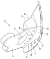
- a helmet 1 is a full-face type motorcycle helmet, and includes a hemispherical cap shell 3 and an impact absorbing member 4 disposed along the inner surface of the cap shell 3.
- the cap shell 3 is formed of fiber reinforced resin, hard resin, metal, or the like, and has a top cover 7, a occipital cover 8, a pair of left and right cheek covers 9, and a chin cover 10. Protrudes forward from the lower side of the left and right cheek covering portions 9 so as to cover the mouth from the chin of the helmet wearer.
- the cap shell 3 is provided with an opening 13 for wearing the helmet 1 at its lower end as shown in FIG.
- the opening edge of the mounting opening 13 includes a lower end edge 8 a of the occipital covering portion 8, a lower end edge 9 a of the left and right cheek covering portions 9, and a lower end edge 10 a of the chin covering portion 10.
- a front opening window 14 is formed between the top cover 7 and the chin cover 10 and between the front ends of the left and right cheek covers 9.
- the front opening window 14 is covered with a translucent shield plate 15 so as to be freely opened and closed.
- the shock absorbing member 4 is formed of a foamed resin such as polystyrene foam, and a head cover that is not shown corresponding to the head cover 7 of the cap shell 3 and a head cover that is not shown corresponding to the head cover 8 and the left and right cheeks.
- a pair of left and right cheek covers 18 corresponding to the cover 9 and a chin cover 19 corresponding to the chin cover 10 are provided.
- the top cover body, the back head cover body, the left and right cheek cover bodies 18 and the chin cover body 19 of the shock absorbing member 4 may be integrally formed as a whole, or they may be partially formed integrally. Alternatively, each may be formed separately. Further, for example, the chin cover 19 may be divided into three parts: a pair of left and right chin covers and a front part of the chin cover.
- a pair of left and right side edge members 22 are attached to the lower edge 9 a of the left and right cheek cover parts 9, a front edge member 23 is attached to the lower edge 10 a of the chin cover part 10, and the lower edge 8 a of the occipital cover part 8.
- a rear edge member 24 is mounted.
- the left and right side edge members 22, the front edge member 23, and the rear edge member 24 are formed of a rubber material having elasticity or a soft synthetic resin.
- the front edge member 23 includes a front fitting part 26 having a U-shaped cross section that fits to the lower edge 10 a of the chin cover part 10, and a rear side from the lower end of the front fitting part 26.
- the left and right side edge trimming members 22 have a bent front part 27 and a side fitting part 29 having a U-shaped cross section that fits to the lower edge 9a of the cheek covering part 9, and a side fitting. And a side bent edge 30 protruding from the lower end of the joint portion 29.
- the front edge member 23 and the left and right side edge members 22 are integrally formed, and the left and right rear end sides of the front fitting portion 26 are front and rear with respect to the side fitting portions 29 of the left and right side edge members 22, respectively.
- the left and right rear end sides of the front bent edge portion 27 are formed to be continuous in the front and rear direction with respect to the side bent edge portions 30 of the left and right side edge trimming members 22.
- the rear edge member 24 includes a rear fitting portion 32 having a U-shaped cross section that fits to the lower edge of the occipital covering portion 8, and a rear bent edge portion 33 that is bent forward from the lower end of the rear fitting portion 32.
- the left and right side edge members 22 are formed separately from each other.
- a pair of left and right cheek pads 36 are provided inside the impact absorbing member 4 (chin cover 19 and cheek cover 18) corresponding to the chin cover 10 and cheek cover 9.
- the left and right cheek pads 36 include a plate-shaped shape retaining body 37 and a cushion body 38 attached to the inner surface of the shape retaining body 37, and the inside of the cushion body 38 is covered with a covering body 39 such as a cloth.
- the outer peripheral portion and the like are sewn to the outer peripheral portion and the like of the shape retaining body 37, and the covering body 39 and the shape retaining body 37 surround the cushion body 38.
- the cheek pad 36 is formed with a band through hole 40 through which a below-described chin-hook band 65 is inserted.
- the front ends of the left and right cheek pads 36 are separated from each other right and left in front of the helmet wearer's mouth.
- a banding hole corresponding to the banding hole 40 is also formed in the impact absorbing member 4 (cheek covering body 18) corresponding to the cheek covering part 9.
- the left and right cheek pads 36 are respectively provided with insertion locking pieces 41 folded upward from the outer end side in the left-right direction at the lower end of the cheek pad 36, and the insertion locking pieces 41 are provided on the side edge member 22.
- the left and right cheek pads 36 are held inside the shock absorbing member 4 by being inserted between the chin cover 10 and the cheek cover 9 and the corresponding shock absorbing members 4 through the left and right inner sides. .
- a pair of left and right air passages 44 are provided inside the chin cover 10 and the cheek cover 9.
- the left and right air passages 44 allow exhalation to flow backward from the front side of the chin cover part 10 toward the rear part of the cheek cover part 9, and shock absorbing members corresponding to the chin cover part 10 and the cheek cover part 9.
- 4 (jaw cover body 19 and cheek cover body 18) are provided with passage-forming grooves that are recessed inward in the left-right direction on the outer surface, thereby providing jaw support 10 and cheek cover 9 and corresponding impacts.
- the air passages 44 are formed between the absorbent member 4 (the chin cover body 19 and the cheek cover body 18), and the air passages 44 are formed inside the chin cover part 10 and the cheek cover part 9 from the front part of the chin cover part 10 to the cheek cover part 9. It is formed over the rear part.
- a pair of left and right mouth communication holes 46 are provided in the shock absorbing member 4 (front part of the chin cover 19) located in front of the mouth of the helmet wearer.
- Each mouth communication hole 46 is formed in the front and rear of the chin cover 19 so as to penetrate inside and outside, and communicates with the front portions of the left and right air passages 44, respectively.
- the left and right mouth communication holes 46 are disposed in front of the front ends of the left and right cheek pads 36 so that exhaled air is sent to the front portion of the air passage 44 through the mouth communication holes 46.
- a notch recess 50 is provided on the lower end side of the left and right cheek covering portions 9 so as to be cut upward, so that the lower end edge 9a of the left and right cheek covering portions 9 extends from the front and rear sides to the front and rear center. It is formed in a mountain shape inclined upward.
- a wide portion 52 is formed in the side edge member 22 so as to bulge upward in a mountain shape corresponding to the notch recess 50 and have a wide vertical width.
- the portion corresponding to the wide portion 52 of the side fitting portion 29 has a mountain shape so as to incline upward from the front and rear sides toward the front and rear center along the lower edge 9a of the cheek covering portion 9 corresponding to the notch recess 50. Is curved.
- the portion corresponding to the wide portion 52 of the side bent edge portion 30 is a wide bent edge portion 30a that protrudes wide downward from the side fitting portion 29, and the wide bent edge portion 30a It protrudes downward while inclining from the part fitting part 29 toward the inner side in the left-right direction.
- the front side of the wide part 52 of the side bent edge 30 is gradually bent from the side fitting part 29 to the inner side in the left-right direction as it goes forward, and the front bent edge of the front edge member 23 27 is continuous in the front-rear direction with respect to the rear portion.
- the side portion fitting portion 29 is gradually bent toward the inner side in the left-right direction.
- an air extraction hole 55 is provided in the wide portion 52 of the side edge member 22.
- a plurality of the air outlet holes 55 are spaced apart from the wide bent edge 30a of the side bent edge 30 in the front-rear direction (four in the illustrated example with respect to the wide portions 52 of the left and right side edge members 22). Each).
- the plurality of air extraction holes 55 are located in a wide portion 52 that bulges upward corresponding to the notch recess 50, and is disposed at a position higher than a line segment connecting the front lower end and the rear lower end of the cap shell 3. ing.
- a plurality of outside air guide surfaces 57 are formed on the outer surface of the wide bent edge 30 a of the side edge member 22.
- the outside air guide surface 57 is on the rear side or the front side of the air extraction hole 55 and is inclined so as to gradually go to the left and right outwards from the rear opening edge of the air extraction hole 55 or in front of the air extraction hole 55. As it goes forward from the opening edge, it gradually inclines toward the left and right inward.
- the plurality of outside air guide surfaces 57 are respectively disposed between the air outlet holes 55 adjacent to the front and rear of the wide bent edge portion 30a, and are rearward from the rear opening edge of the front air outlet hole 55. It is inclined so as to gradually go to the left and right as it goes rearward toward the front opening edge of the side air outlet hole 55.
- the lower end side of the shock absorbing member 4 (cheek covering body 18) corresponding to the cheek covering part 9 is not provided with a concave part corresponding to the notch concave part 50, and corresponds to the cheek covering part 9.
- the rear lower side of the air passage 44 is located on the left and right inner sides of the wide portion 52 of the side edge member 22 and communicates with a plurality of air extraction holes 55 of the side edge member 22.
- the cheek pad 36 is formed with a plurality of pad communication holes 58 communicating with the inside air communication holes 47 so as to penetrate inside and outside.
- Each pad communication hole 58 is formed in the left-right direction over the shape retaining body 37 and the cushion body 38 with the covering body 39 left. 3, 4, 7, and 8, an air hole 59 is provided in a portion corresponding to the air extraction hole 55 of the insertion locking piece 41 so that the outer surface of the insertion locking piece 41 covers the air hole 59.
- a mesh sheet 60 is attached thereto.
- the air holes 59 may be arranged so as to coincide with the air extraction holes 55 in the front-rear direction and the up-down direction, or may be arranged slightly shifted in the front-rear direction or the up-down direction.
- a covering body extension 61 is provided at the lower end of the covering body 39 so as to project outwardly from the left and right sides of the shape retaining body 37, and the projecting end of the covering body extension 61 is sewn to the lower outer surface of the insertion locking piece 41. Has been.
- a connecting sheet body 63 formed of a cloth or the like is provided between the lower end portion of the insertion locking piece 41 and the lower end portion of the shape retaining body 37, and one end portion in the width direction of the connecting sheet body 63 is formed on the shape retaining body 37. It is sewn on the outer surface of the lower end.
- the other end of the connecting sheet 63 in the width direction and the covering extension 61 are overlapped with each other, and the other end of the connecting sheet 63 in the width direction is attached to the lower outer surface of the insertion locking piece 41.
- the connecting sheet body 63 and the covering body extension 61 connect the insertion locking piece 41 to the lower end of the cheek pad 36 so as to be foldable. Yes.
- a pair of left and right chin rest bands 65 are connected and fixed to the inner surfaces of the left and right cheek covers 9, respectively, so that the shock absorbing member 4 (chin cover) corresponding to the cheek covers 9 is obtained.
- 19) is inserted through the band through hole 40 of the cheek pad 36 and the band through hole 40 of the cheek pad 36 and protrudes downward through the side edge member 22 and the left and right inner sides of the cheek pad 36.
- the wide portion 52 of the side edge member 22 is disposed at a position corresponding to the chin band 65.
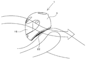
- the wind flows from the front side toward the rear side of the cap body shell 3 as shown in FIG. As shown in FIG. 6, the wind is guided so as to be bent outward by a plurality of outside air guide surfaces 57, so that the outside of the plurality of air extraction holes 55 is made negative pressure, and a plurality of air in the helmet 1 is supplied.
- the air can be sucked to the outside through the air outlet hole 55.
- the air in the cap shell 3 can be effectively sucked to the outside by the plurality of air extraction holes 55 arranged in the front-rear direction, and the air in the helmet 1 is taken out from the plurality of air extraction holes 55 to the outside.
- the inside of the helmet 1 can be sufficiently ventilated.
- the air extraction hole 55 is provided in the wide portion 52 that bulges upward corresponding to the notch recess 50, and the air extraction hole 55 can be arranged at a higher position with respect to the cap shell 3.
- the air extraction hole 55 can be disposed at a position higher than a line segment connecting the front lower end and the rear lower end of the cap shell 3, so that the outer side of the cap shell 3 is directed from the front to the rear. The air in the helmet 1 can be effectively and smoothly sucked to the outside through the air extraction hole 55 by the flowing wind.
- the breath of the helmet wearer is sent to the front of the air passage 44 through the mouth communication hole 46 from between the front ends of the left and right cheek pads 36, and then sent to the rear of the air passage 44. Then, the air is discharged from the plurality of air extraction holes 55 to the outside of the helmet.
- the rear lower side of the air passage 44 is located on the left and right inner sides of the wide portion 52 of the side edge member 22 and communicates with the air outlet hole 55 of the side edge member 22. Due to the suction force that sucks air from the air outlet hole 55 to the outside, the exhaled air that has entered the air passage 44 is also sucked toward the air outlet hole 55, so that the exhaled air smoothly flows backward through the air passage 44.
- the air is discharged from the lower rear side to the air extraction hole 55 and is smoothly discharged from the air extraction hole 55 to the outside.
- the shock absorbing member 4 corresponding to the chin cover portion 10 and the cheek cover portion 9 is formed with an inside air communication hole 47 communicating with the air passage 44 from the inner surface, and the cheek pad 36 is a pad communicating with the inside air communication hole 47. Since the communication hole 58 is formed, the inside air inside the shock absorbing member 4 and the cheek pad 36 is sent to the air passage 44 through the pad communicating hole 58 and the inside air communicating hole 47, and not only the exhalation but also the shock absorbing member 4 Also, the inside air inside the cheek pad 36 can be smoothly delivered to the outside through the air passage 44 through the air outlet hole 55, and the inside of the helmet 1 can be ventilated more reliably.
- the air passage 44 is provided on the outer surface of the impact absorbing member 4 corresponding to the chin cover 10 and the cheek cover 9 in the front-rear direction by immersing the passage formation groove inward in the left-right direction.
- the air passage 44 is formed between the chin cover 10 and the cheek cover 9 by providing the shock absorption member 4 with a passage forming groove. Can be easily formed inside.
- the left and right cheek pads 36 are provided with insertion locking pieces 41 that are folded upward from the left and right outer end sides of the lower end of the cheek pad 36, and the insertion locking pieces 41 are provided on the side edge member 22. Since the cheek pad 36 is held inside the shock absorbing member 4 by being inserted between the chin covering portion 10 and the cheek covering portion 9 and the corresponding shock absorbing members 4 through the left and right inner sides thereof, The pair of left and right cheek pads 36 can be easily and reliably held inside the impact absorbing member 4 corresponding to the chin cover 10 and the cheek cover 9 by the insertion locking pieces 41.
- air holes 59 are provided in portions corresponding to the air extraction holes 55 of the insertion locking pieces 41, and the mesh sheet 60 is attached to the insertion locking pieces 41 so as to cover the air holes 59. It is possible to prevent the air in the helmet 1 from being taken out to the outside by closing the air extraction hole 55 with the locking piece 41.
- a pair of left and right chin straps 65 are connected and fixed to the inner surfaces of the left and right cheek covers 9 and protrude downward through the left and right inner sides of the side edge member 22, so that the side edge member 22 has a wider width.
- the portion 52 is disposed at a position corresponding to the chin rest band 65, when the helmet 1 is put on the mounting opening 13, the left and right chin rest bands 65 are pulled to the outside in the left and right directions.
- the wide portion 52 of the edge trimming member 22 spreads in a skirt shape outwardly in the left-right direction together with the cheek pad 36 and the lower portion of the shock absorbing member 4, so that the head can be easily inserted into the helmet through the mounting opening 13. And the helmet 1 can be easily put on.
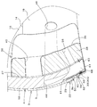
- FIG. 10 shows a second embodiment, and the impact absorbing member 4 (cheek covering body 18) corresponding to the cheek covering portion 9 is substantially the same as the lower end edge 9a of the cheek covering portion 9 whose lower end edge corresponds to the notch 50.
- the shock absorbing member 4 is formed so as to have the same height in the vertical direction and is recessed above the wide portion 52 of the side edge member 22 and the lower portion of the cheek pad 36 and corresponding to the cheek covering portion 9.
- a gap passage 68 surrounded by the side edge member 22, the cheek pad 36 and the connecting sheet body 63 is formed between the wide portion 52 of the side edge member 22 and the lower portion of the cheek pad 36. Yes.
- a lower side of the air passage 44 is communicated with the gap passage 68, and a pad communication hole 58 is formed in the lower part of the cheek pad 36 so as to communicate with the gap passage 68 so as to penetrate inside and outside.
- One or a plurality of pad communication holes 58 are formed on the left and right cheek pads 36 at intervals in the front and rear. The other points are the same as those in the first embodiment.
- the inside air communication hole 47 of the shock absorbing member 4 in the first embodiment may be omitted or provided.
- the wind flowing from the front side toward the rear side of the cap shell shell 3 is guided to be bent outward by the plurality of outside air guide surfaces 57.
- the air in the cap shell shell 3 can be effectively sucked to the outside by the plurality of air extraction holes 55 arranged in the front-rear direction, and the air in the helmet 1 is externally extracted from the plurality of air extraction holes 55.
- the inside of the helmet 1 can be sufficiently ventilated.
- the breath of the helmet wearer is sent from between the front ends of the left and right cheek pads 36 to the front portion of the air passage 44 through the mouth communication hole 46, and then sent to the rear of the air passage 44 to enter the gap passage 68.
- the air is discharged from the gap passage 68 to the outside of the helmet 1 through the plurality of air extraction holes 55.
- the inside air inside the cheek pad 36 is sent to the gap passage 68 through the pad communication hole 58, and not only exhalation but also the inside air inside the cheek pad 36 smoothly passes through the gap passage 68 from the air outlet hole 55 to the outside. Can be sent out.
- the helmet 1 is a full face type helmet having the chin cover part 10, but the helmet 1 is not limited to the full face type, and is an open face type without the chin cover part 10. It may be a helmet.
- the four air extraction holes 55 are provided in the wide portion 52 of the side edge member 22 at intervals in the front-rear direction. However, the number of the air extraction holes 55 is not limited to this. One to three or five or more may be provided.
- the passage forming groove is formed in the front-rear direction on the outer surface of the shock absorbing member 4 corresponding to the chin cover portion 10 and the cheek cover portion 9 so that the exhaled air flows backward toward the air extraction hole 55.
- the air passage 44 is formed between the chin cover 10 and the cheek cover 9 and the shock absorbing member 4 corresponding thereto, but instead, corresponds to the chin cover 10 and the cheek cover 9.
- a passage forming groove that is recessed inward in the left-right direction is formed on the outer surface of the shock absorbing member 4 corresponding to the chin cover 10 and the cheek cover 9 in the front-rear direction, so that exhaled air is directed toward the air extraction hole 55.
- the air passage 44 that flows out rearward may be formed between the impact absorbing member 4 and the cheek pad 36 inside the chin cover 10 and the cheek cover 9.
- the shock absorbing member 4 located in front of the helmet wearer's mouth is provided with a pair of left and right mouth communication holes 46.
- the shock absorbing member 4 is located in front of the helmet wearer's mouth.
- the shock absorbing member 4 may be provided with one port communication hole 46, and the port communication hole 46 may be communicated with the front portions of the left and right air passages 44.
Landscapes
- Helmets And Other Head Coverings (AREA)
Abstract
Description
この種の従来のヘルメットでは、帽体シェルの左右の頬覆い部に空気取出孔を設け、この空気取出孔からヘルメット内の空気を取り出してヘルメット内を換気するようにしていた(例えば、特許文献1)。
本発明は上記問題点に鑑み、帽体シェルの強度を低下させることなく換気することができるヘルメットを提供することを目的としている。
この技術的課題を解決する本発明の技術的手段は、帽体シェル3と帽体シェル3の内面に沿って配置された衝撃吸収部材4とを備え、帽体シェル3は左右一対の頬覆い部9を有し、左右の頬覆い部9の下端縁9aに側部縁取部材22が装着されたヘルメットであって、
左右の頬覆い部9の下端側に上方に向けて切り欠かれた切欠き凹部50が設けられて、左右の頬覆い部9の下端縁9aが前後両側から前後中央に向けて上方に傾斜した山形状に形成され、
側部縁取部材22に、切欠き凹部50に対応して上方に向けて山形状に膨出して上下幅が広くなった幅広部52が形成され、この幅広部52に空気取出孔55が設けられている点にある。
また、本発明の他の技術的手段は、前記空気取出孔55は、側部縁取部材22の幅広部52に前後方向に間隔をおいて複数個設けられ、前記外気案内面57は、前後に隣合う空気取出孔55間にそれぞれ配置され、前側の空気取出孔55の後側開口縁から後側の空気取出孔55の前側開口縁に向けて後方に行くに従って除々に左右外方に向かうように傾斜されている点にある。
また、本発明の他の技術的手段は、ヘルメット装着者の口の前側に位置する衝撃吸収部材4に、前記空気通路44の前部に連通する口連通孔46が設けられている点にある。
また、本発明の他の技術的手段は、顎覆い部10及び頬覆い部9に対応する衝撃吸収部材4に、その内面から空気通路44に連通する内気連通孔47が形成されている点にある。
また、本発明の他の技術的手段は、前記顎覆い部10及び頬覆い部9に対応する衝撃吸収部材4の内側に左右一対の頬パッド36が設けられ、左右の頬パッド36には、頬パッド36下端部の左右方向の外端側から上方に折り返された差し込み係止片41が設けられており、差し込み係止片41が側部縁取部材22の左右内側を通って顎覆い部10及び頬覆い部9とこれらに対応する衝撃吸収部材4との間に挿入されることにより、頬パッド36が衝撃吸収部材4の内側に保持され、
前記差し込み係止片41の空気取出孔55に対応する部分に空気孔59が設けられ、差し込み係止片41に空気孔59を覆うようにメッシュシート60が添設されている点にある。
また、本発明の他の技術的手段は、左右一対の顎掛け用バンド65が左右の頬覆い部9の内面側にそれぞれ連結固定されて前記側部縁取部材22の左右内側を通って下方に突出され、側部縁取部材22の幅広部52が顎掛け用バンド65に対応する位置に配置されている点にある。
しかも、空気取出孔は、切欠き凹部に対応して上方に膨出した側部縁取部材の幅広部に設けられており、空気取出孔を帽体シェルに対してより高い位置に配置することができ、例えば帽体シェルの前部下端と後部下端を結ぶ線分よりも高い位置に空気取出孔を配置することが可能になる。このため、帽体シェルの外側方を前から後に向けて流れる風によってヘルメット内の空気を空気取出孔から外部に効果的に吸引することができるようになり、側部縁取部材の幅広部に設けられた空気取出孔からヘルメット内の空気を外部に取り出してヘルメット内を十分に換気することができる。
図1~図9は本発明の第1実施形態を示している。図1~図4において、ヘルメット1は、フルフェース型のバイク用のヘルメットで、半球状の帽体シェル3と帽体シェル3の内面に沿って配置された衝撃吸収部材4とを備える。
帽体シェル3は、繊維強化樹脂や硬質樹脂又は金属等で形成され、頭頂覆い部7と後頭覆い部8と左右一対の頬覆い部9と顎覆い部10とを有し、顎覆い部10は左右の頬覆い部9の下側から前方に突出してヘルメット装着者の顎から口を覆うようになっている。
頭頂覆い部7と顎覆い部10との間であって左右の頬覆い部9の前端部間に前面開口窓14が形成されている。前面開口窓14は透光性を有するシールド板15で開閉自在に覆われている。
なお、衝撃吸収部材4の頭頂覆い体と後頭覆い体と左右の頬覆い体18と顎覆い体19とは、これら全体を一体に形成してもよいし、これらを部分的に一体に形成してもよいし、それぞれを別体に形成するようにしてもよい。また、例えば、顎覆い体19を左右一対の顎覆い体側部と顎覆い体前部とに3分割するようにしてもよい。
図5にも示すように、前部縁取部材23は、顎覆い部10の下端縁10aに嵌合する断面U字状の前嵌合部26と、前嵌合部26の下端から後側に折れ曲がった前折曲縁部27とを有し、左右の側部縁取部材22は、頬覆い部9の下端縁9aに嵌合する断面U字状の側部嵌合部29と、側部嵌合部29の下端から突出された側部折曲縁部30とを有している。
後部縁取部材24は後頭覆い部8の下端縁に嵌合する断面U字状の後嵌合部32と、後嵌合部32の下端から前側に折れ曲がった後折曲縁部33とを有し、左右の側部縁取部材22とは別体に形成されている。
図1及び図2において、左右の頬覆い部9の下端側に上方に向けて切り欠かれた切欠き凹部50が設けられて、左右の頬覆い部9の下端縁9aが前後両側から前後中央に向けて上方に傾斜した山形状に形成されている。
側部嵌合部29の幅広部52に対応する部分は、切欠き凹部50に対応する頬覆い部9の下端縁9aに沿って前後両側から前後中央に向けて上方に傾斜するように山形状に湾曲されている。
側部折曲縁部30の幅広部52よりも前側は前方に向かうに従って側部嵌合部29から左右方向の内方側に次第に大きく折れ曲がっており、前部縁取部材23の前折曲縁部27の後部に対して前後に連続するようになっている。側部折曲縁部30の幅広部52よりも後側も後方に向かうに従って側部嵌合部29から左右方向の内方側に次第に大きく折れ曲がっている。
複数の空気取出孔55は、切欠き凹部50に対応して上方に膨出した幅広部52にあって、帽体シェル3の前部下端と後部下端を結ぶ線分よりも高い位置に配置されている。
本実施の形態では、複数の外気案内面57は、幅広折曲縁部30aの前後に隣合う空気取出孔55間にそれぞれ配置されており、前側の空気取出孔55の後側開口縁から後側の空気取出孔55の前側開口縁に向けて後方に行くに従って除々に左右外方に向かうように傾斜されている。
図3、図4、図7及び図8において、前記差し込み係止片41の空気取出孔55に対応する部分に空気孔59が設けられ、差し込み係止片41の外面に空気孔59を覆うようにメッシュシート60が添設されている。
被覆体39の下端部に、保形体37よりも左右外方に延長突出した被覆体延長部61が設けられ、被覆体延長部61の突出端部は差し込み係止片41の下部外面に縫着されている。また、差し込み係止片41の下端部と保形体37の下端部との間に布等で形成した連結シート体63が設けられ、この連結シート体63の幅方向の一端部は保形体37の下端部外面に縫着されている。連結シート体63の幅方向の他端側と前記被覆体延長部61とは互いに重合され、連結シート体63の幅方向の他端部は差し込み係止片41の下部外面に被覆体延長部61の突出端部及びメッシュシート60の下部と共に縫着されており、連結シート体63と被覆体延長部61とは差し込み係止片41を頬パッド36の下端部に対して折り曲げ自在に連結している。
しかも、空気取出孔55は、切欠き凹部50に対応して上方に膨出した幅広部52に設けられており、空気取出孔55を帽体シェル3に対してより高い位置に配置することができ、例えば帽体シェル3の前部下端と後部下端を結ぶ線分よりも高い位置に空気取出孔55を配置することが可能になるため、帽体シェル3の外側方を前から後に向けて流れる風によってヘルメット1内の空気を空気取出孔55から外部に有効かつスムーズに吸引することができるようになる。
この際に、空気通路44の後部下側は側部縁取部材22の幅広部52の左右内側に位置して側部縁取部材22の空気取出孔55に連通されているので、上記ヘルメット1内の空気を空気取出孔55から外部に吸引する吸引力によって、空気通路44に入った呼気も空気取出孔55に向けて吸引されるため、呼気は空気通路44をスムーズに後方に流れて空気通路44の後部下側から空気取出孔55へと送出され、空気取出孔55から外部にスムーズに排出される。
また、左右一対の顎掛け用バンド65が左右の頬覆い部9の内面側にそれぞれ連結固定されて前記側部縁取部材22の左右内側を通って下方に突出され、側部縁取部材22の幅広部52が顎掛け用バンド65に対応する位置に配置されているので、ヘルメット1を装着用開口13から被る際に、左右の顎掛け用バンド65を互いに左右方向外方に引っ張ることにより、側部縁取部材22の幅広部52が頬パッド36及び衝撃吸収部材4の下部と共に左右方向外方にスカート状に大きく広がるようになり、このため装着用開口13から頭をヘルメット内に楽に挿入することができ、ヘルメット1を容易に被ることができるようになる。
また、頬パッド36の内側にある内気はパッド連通孔58を通して空隙通路68に送出され、呼気ばかりではなく頬パッド36の内側にある内気も、空隙通路68を通して空気取出孔55からスムーズに外部に送出することができる。
また、前記実施形態では、側部縁取部材22の幅広部52に空気取出孔55が前後方向に間隔をおいて4個設けられているが、空気取出孔55を設ける個数はこれに限定されず、1~3個又は5個以上設けるようにしてもよい。
3 帽体シェル
4 衝撃吸収部材
7 頭頂覆い部
8 後頭覆い部
8a 下端縁
9 頬覆い部
9a 下端縁
10 顎覆い部
10a 下端縁
13 装着用開口
14 前面開口窓
15 シールド板
22 側部縁取部材
23 前部縁取部材
24 後部縁取部材
26 前嵌合部
27 前折曲縁部
29 側部嵌合部
30 側部折曲縁部
30a 幅広折曲縁部
32 後嵌合部
33 後折曲縁部
36 頬パッド
41 差し込み係止片
44 空気通路
46 口連通孔
47 内気連通孔
50 切欠き凹部
52 幅広部
55 空気取出孔
57 外気案内面
58 パッド連通孔
59 空気孔
60 メッシュシート
65 顎掛け用バンド
68 空隙通路
Claims (15)
- 帽体シェル(3)と帽体シェル(3)の内面に沿って配置された衝撃吸収部材(4)とを備え、帽体シェル(3)は左右一対の頬覆い部(9)を有し、左右の頬覆い部(9)の下端縁(9a)に側部縁取部材(22)が装着されたヘルメットであって、
左右の頬覆い部(9)の下端側に上方に向けて切り欠かれた切欠き凹部(50)が設けられて、左右の頬覆い部(9)の下端縁(9a)が前後両側から前後中央に向けて上方に傾斜した山形状に形成され、
側部縁取部材(22)に、切欠き凹部(50)に対応して上方に向けて山形状に膨出して上下幅が広くなった幅広部(52)が形成され、この幅広部(52)に空気取出孔(55)が設けられていることを特徴とするヘルメット。 - 側部縁取部材(22)は、頬覆い部(9)の下端縁(9a)に嵌合する断面U字状の側部嵌合部(29)と、側部嵌合部(29)の下端から突出された側部折曲縁部(30)とを有し、側部嵌合部(29)の幅広部(52)に対応する部分は、頬覆い部(9)の下端縁(9a)に沿って前後両側から前後中央に向けて上方に傾斜するように山形状に湾曲され、側部折曲縁部(30)の幅広部(52)に対応する部分は、側部嵌合部(29)から幅広に下方に突出された幅広折曲縁部(30a)とされ、この幅広折曲縁部(30a)に前記空気取出孔(55)が形成されていることを特徴とする請求項1に記載のヘルメット。
- 側部縁取部材(22)の外面に、空気取出孔(55)の後開口縁から後方に行くに従って除々に左右外方に向かうように傾斜し又は空気取出孔(55)の前開口縁から前方に行くに従って除々に左右内方に向かうように傾斜した外気案内面(57)が形成されていることを特徴とする請求項1に記載のヘルメット。
- 前記空気取出孔(55)は、側部縁取部材(22)の幅広部(52)に前後方向に間隔をおいて複数個設けられ、前記外気案内面(57)は、前後に隣合う空気取出孔(55)間にそれぞれ配置され、前側の空気取出孔(55)の後側開口縁から後側の空気取出孔(55)の前側開口縁に向けて後方に行くに従って除々に左右外方に向かうように傾斜されていることを特徴とする請求項3に記載のヘルメット。
- 前記帽体シェル(3)は、左右の頬覆い部(9)の下側から前方に突出して顎から口を覆う顎覆い部(10)を有し、顎覆い部(10)及び頬覆い部(9)の内側に、呼気を前記空気取出孔(55)に向けて後方に流出させる空気通路(44)が形成されていることを特徴する請求項1に記載のヘルメット。
- ヘルメット装着者の口の前側に位置する衝撃吸収部材(4)に、前記空気通路(44)の前部に連通する口連通孔(46)が設けられていることを特徴とする請求項5に記載のヘルメット。
- 頬覆い部(9)に対応する衝撃吸収部材(4)の下端側は、切欠き凹部(50)に対応する頬覆い部(9)の下端縁(9a)よりも下方に突出されて、側部縁取部材(22)の幅広部(52)の左右内側まで伸びており、前記空気通路(44)の後部下側は側部縁取部材(22)の幅広部(52)の左右内側に位置し側部縁取部材(22)の空気取出孔(55)に連通されていることを特徴する請求項5に記載のヘルメット。
- 顎覆い部(10)及び頬覆い部(9)に対応する衝撃吸収部材(4)の外面に左右方向内方に向けて没入した通路形成溝を前後方向に設けることにより、前記空気通路(44)が顎覆い部(10)及び頬覆い部(9)とこれらに対応する衝撃吸収部材(4)との間に形成されていることを特徴する請求項5に記載のヘルメット。
- 顎覆い部(10)及び頬覆い部(9)に対応する衝撃吸収部材(4)に、その内面から空気通路(44)に連通する内気連通孔(47)が形成されていることを特徴する請求項8に記載のヘルメット。
- 前記顎覆い部(10)及び頬覆い部(9)に対応する衝撃吸収部材(4)の内側に左右一対の頬パッド(36)が設けられ、該各頬パッド(36)には前記内気連通孔(47)に連通するパッド連通孔(58)が内外貫通状に形成されていることを特徴する請求項9に記載のヘルメット。
- 前記顎覆い部(10)及び頬覆い部(9)に対応する衝撃吸収部材(4)の内側に左右一対の頬パッド(36)が設けられ、左右の頬パッド(36)には、頬パッド(36)下端部の左右方向の外端側から上方に折り返された差し込み係止片(41)が設けられており、差し込み係止片(41)が側部縁取部材(22)の左右内側を通って顎覆い部(10)及び頬覆い部(9)とこれらに対応する衝撃吸収部材(4)との間に挿入されることにより、頬パッド(36)が衝撃吸収部材(4)の内側に保持され、
前記差し込み係止片(41)の空気取出孔(55)に対応する部分に空気孔(59)が設けられ、差し込み係止片(41)に空気孔(59)を覆うようにメッシュシート(60)が添設されていることを特徴とする請求項5に記載のヘルメット。 - 左右の頬パッド(36)の前端同士は、ヘルメット装着者の口の前方で互いに左右に離間され、ヘルメット装着者の口の前側に位置する衝撃吸収部材(4)に、前記空気通路(44)の前部に連通する口連通孔(46)が設けられ、この口連通孔(46)は左右の頬パッド(36)の前端間に配置されていることを特徴とする請求項11に記載のヘルメット。
- 左右一対の顎掛け用バンド(65)が左右の頬覆い部(9)の内面側にそれぞれ連結固定されて前記側部縁取部材(22)の左右内側を通って下方に突出され、側部縁取部材(22)の幅広部(52)が顎掛け用バンド(65)に対応する位置に配置されていることを特徴とする請求項1に記載のヘルメット。
- 前記顎覆い部(10)及び頬覆い部(9)に対応する衝撃吸収部材(4)の内側に左右一対の頬パッド(36)が設けられ、頬覆い部(9)に対応する衝撃吸収部材(4)の下端側は側部縁取部材(22)の幅広部(52)及び頬パッド(36)の下部よりも上方に凹んでおり、衝撃吸収部材(4)の下方であって側部縁取部材(22)の幅広部(52)と頬パッド(36)の下部との間に空隙通路(68)が形成され、前記空気通路(44)の下部側が空隙通路(68)に連通されていることを特徴する請求項5に記載のヘルメット。
- 頬パッド(36)の下部に空隙通路(68)に連通するパッド連通孔(58)が内外貫通状に形成されていることを特徴する請求項14に記載のヘルメット。
Priority Applications (6)
| Application Number | Priority Date | Filing Date | Title |
|---|---|---|---|
| CN201180073349.2A CN103796539A (zh) | 2011-11-04 | 2011-11-04 | 头盔 |
| US14/353,319 US20140259311A1 (en) | 2011-11-04 | 2011-11-04 | Helmet |
| PCT/JP2011/075462 WO2013065176A1 (ja) | 2011-11-04 | 2011-11-04 | ヘルメット |
| EP11874968.8A EP2774500B1 (en) | 2011-11-04 | 2011-11-04 | Helmet |
| JP2013541565A JP5848774B2 (ja) | 2011-11-04 | 2011-11-04 | ヘルメット |
| AU2011380179A AU2011380179A1 (en) | 2011-11-04 | 2011-11-04 | Helmet |
Applications Claiming Priority (1)
| Application Number | Priority Date | Filing Date | Title |
|---|---|---|---|
| PCT/JP2011/075462 WO2013065176A1 (ja) | 2011-11-04 | 2011-11-04 | ヘルメット |
Publications (1)
| Publication Number | Publication Date |
|---|---|
| WO2013065176A1 true WO2013065176A1 (ja) | 2013-05-10 |
Family
ID=48191567
Family Applications (1)
| Application Number | Title | Priority Date | Filing Date |
|---|---|---|---|
| PCT/JP2011/075462 Ceased WO2013065176A1 (ja) | 2011-11-04 | 2011-11-04 | ヘルメット |
Country Status (6)
| Country | Link |
|---|---|
| US (1) | US20140259311A1 (ja) |
| EP (1) | EP2774500B1 (ja) |
| JP (1) | JP5848774B2 (ja) |
| CN (1) | CN103796539A (ja) |
| AU (1) | AU2011380179A1 (ja) |
| WO (1) | WO2013065176A1 (ja) |
Cited By (1)
| Publication number | Priority date | Publication date | Assignee | Title |
|---|---|---|---|---|
| WO2022085234A1 (ja) | 2020-10-19 | 2022-04-28 | 株式会社Shoei | ヘルメット及びチークパッド |
Families Citing this family (2)
| Publication number | Priority date | Publication date | Assignee | Title |
|---|---|---|---|---|
| JP6744186B2 (ja) * | 2016-09-30 | 2020-08-19 | 山本光学株式会社 | 保護眼鏡 |
| EP4101329A1 (en) * | 2017-01-25 | 2022-12-14 | Bell Sports, Inc. | Helmet with integrated shoulder pad |
Citations (4)
| Publication number | Priority date | Publication date | Assignee | Title |
|---|---|---|---|---|
| JPS6350510A (ja) * | 1986-04-09 | 1988-03-03 | 東急建設株式会社 | ヘルメツト |
| JPH02110634U (ja) * | 1989-02-18 | 1990-09-04 | ||
| JPH07197305A (ja) | 1993-12-28 | 1995-08-01 | Arai Herumetsuto:Kk | 側面換気構造を備えたヘルメット |
| JPH10168639A (ja) * | 1996-12-16 | 1998-06-23 | Arai Helmet:Kk | 乗車用ヘルメット |
Family Cites Families (5)
| Publication number | Priority date | Publication date | Assignee | Title |
|---|---|---|---|---|
| DE3233467C2 (de) * | 1982-09-09 | 1985-03-28 | Bayerische Motoren Werke AG, 8000 München | Schutzhelm für Motorradfahrer o. dgl. |
| US4555816A (en) * | 1984-01-23 | 1985-12-03 | Bell Helmets Inc. | Ventilated helmet |
| JP2904416B1 (ja) * | 1998-06-23 | 1999-06-14 | 株式会社アライヘルメット | フルフェース型ヘルメット |
| KR100468348B1 (ko) * | 2003-03-24 | 2005-01-27 | 주식회사 홍진에이치제이씨 | 헬멧용 에어벤트 |
| US7207071B2 (en) * | 2004-06-18 | 2007-04-24 | Fox Racing, Inc. | Ventilated helmet system |
-
2011
- 2011-11-04 EP EP11874968.8A patent/EP2774500B1/en not_active Not-in-force
- 2011-11-04 AU AU2011380179A patent/AU2011380179A1/en not_active Abandoned
- 2011-11-04 WO PCT/JP2011/075462 patent/WO2013065176A1/ja not_active Ceased
- 2011-11-04 US US14/353,319 patent/US20140259311A1/en not_active Abandoned
- 2011-11-04 CN CN201180073349.2A patent/CN103796539A/zh active Pending
- 2011-11-04 JP JP2013541565A patent/JP5848774B2/ja not_active Expired - Fee Related
Patent Citations (4)
| Publication number | Priority date | Publication date | Assignee | Title |
|---|---|---|---|---|
| JPS6350510A (ja) * | 1986-04-09 | 1988-03-03 | 東急建設株式会社 | ヘルメツト |
| JPH02110634U (ja) * | 1989-02-18 | 1990-09-04 | ||
| JPH07197305A (ja) | 1993-12-28 | 1995-08-01 | Arai Herumetsuto:Kk | 側面換気構造を備えたヘルメット |
| JPH10168639A (ja) * | 1996-12-16 | 1998-06-23 | Arai Helmet:Kk | 乗車用ヘルメット |
Non-Patent Citations (1)
| Title |
|---|
| See also references of EP2774500A4 |
Cited By (1)
| Publication number | Priority date | Publication date | Assignee | Title |
|---|---|---|---|---|
| WO2022085234A1 (ja) | 2020-10-19 | 2022-04-28 | 株式会社Shoei | ヘルメット及びチークパッド |
Also Published As
| Publication number | Publication date |
|---|---|
| JP5848774B2 (ja) | 2016-01-27 |
| EP2774500A4 (en) | 2015-11-18 |
| CN103796539A (zh) | 2014-05-14 |
| AU2011380179A1 (en) | 2014-04-17 |
| EP2774500A1 (en) | 2014-09-10 |
| EP2774500B1 (en) | 2017-05-03 |
| US20140259311A1 (en) | 2014-09-18 |
| JPWO2013065176A1 (ja) | 2015-04-02 |
Similar Documents
| Publication | Publication Date | Title |
|---|---|---|
| US10959472B2 (en) | Multi-component helmet construction | |
| JP4603724B2 (ja) | ヘルメット用チンカバーおよびこのチンカバーが取り付けられたヘルメット | |
| JPH0623527Y2 (ja) | ヘルメット | |
| JP4895544B2 (ja) | フルフェイス型ヘルメット | |
| US10506841B2 (en) | Football helmet with recessed face guard mounting areas | |
| CN102389348B (zh) | 用于进行户外运动的防护罩 | |
| JP4592871B2 (ja) | ヘルメット | |
| EP0474939B1 (en) | Helmet | |
| US20060031978A1 (en) | Ventilated helmet system | |
| CN102302396B (zh) | 用于进行户外运动的防护罩 | |
| CN102335062A (zh) | 用于进行户外运动的防护罩 | |
| JP6163366B2 (ja) | ヘルメット | |
| JP5215079B2 (ja) | シールドを備えているヘルメット | |
| ITUB20155310A1 (it) | Fascia poggia fronte per caschi e casco provvisto di tale fascia poggia fronte. | |
| JP5848774B2 (ja) | ヘルメット | |
| JP3131987U (ja) | 衝撃吸収帽子 | |
| JPH0641807A (ja) | ヘルメットの通風構造 | |
| JP7288889B2 (ja) | ヘルメット及びチークパッド | |
| ITUD980119A1 (it) | Casco | |
| CN222397169U (zh) | 一种电单车头盔 | |
| CN213663918U (zh) | 一种带透气功能的高抗冲安全帽 | |
| JP4700458B2 (ja) | 頭部保護具 | |
| JP2023059843A (ja) | ヘルメット | |
| JP2019094596A (ja) | ヘルメット |
Legal Events
| Date | Code | Title | Description |
|---|---|---|---|
| 121 | Ep: the epo has been informed by wipo that ep was designated in this application |
Ref document number: 11874968 Country of ref document: EP Kind code of ref document: A1 |
|
| ENP | Entry into the national phase |
Ref document number: 2013541565 Country of ref document: JP Kind code of ref document: A |
|
| REEP | Request for entry into the european phase |
Ref document number: 2011874968 Country of ref document: EP |
|
| WWE | Wipo information: entry into national phase |
Ref document number: 2011874968 Country of ref document: EP |
|
| ENP | Entry into the national phase |
Ref document number: 2011380179 Country of ref document: AU Date of ref document: 20111104 Kind code of ref document: A |
|
| WWE | Wipo information: entry into national phase |
Ref document number: 14353319 Country of ref document: US |
|
| NENP | Non-entry into the national phase |
Ref country code: DE |