WO2013065218A1 - ステント - Google Patents
ステント Download PDFInfo
- Publication number
- WO2013065218A1 WO2013065218A1 PCT/JP2012/005248 JP2012005248W WO2013065218A1 WO 2013065218 A1 WO2013065218 A1 WO 2013065218A1 JP 2012005248 W JP2012005248 W JP 2012005248W WO 2013065218 A1 WO2013065218 A1 WO 2013065218A1
- Authority
- WO
- WIPO (PCT)
- Prior art keywords
- stent
- linear body
- axial direction
- portions
- linear
- Prior art date
- Legal status (The legal status is an assumption and is not a legal conclusion. Google has not performed a legal analysis and makes no representation as to the accuracy of the status listed.)
- Ceased
Links
Images




Classifications
-
- A—HUMAN NECESSITIES
- A61—MEDICAL OR VETERINARY SCIENCE; HYGIENE
- A61F—FILTERS IMPLANTABLE INTO BLOOD VESSELS; PROSTHESES; DEVICES PROVIDING PATENCY TO, OR PREVENTING COLLAPSING OF, TUBULAR STRUCTURES OF THE BODY, e.g. STENTS; ORTHOPAEDIC, NURSING OR CONTRACEPTIVE DEVICES; FOMENTATION; TREATMENT OR PROTECTION OF EYES OR EARS; BANDAGES, DRESSINGS OR ABSORBENT PADS; FIRST-AID KITS
- A61F2/00—Filters implantable into blood vessels; Prostheses, i.e. artificial substitutes or replacements for parts of the body; Appliances for connecting them with the body; Devices providing patency to, or preventing collapsing of, tubular structures of the body, e.g. stents
- A61F2/82—Devices providing patency to, or preventing collapsing of, tubular structures of the body, e.g. stents
- A61F2/86—Stents in a form characterised by the wire-like elements; Stents in the form characterised by a net-like or mesh-like structure
- A61F2/90—Stents in a form characterised by the wire-like elements; Stents in the form characterised by a net-like or mesh-like structure characterised by a net-like or mesh-like structure
- A61F2/91—Stents in a form characterised by the wire-like elements; Stents in the form characterised by a net-like or mesh-like structure characterised by a net-like or mesh-like structure made from perforated sheets or tubes, e.g. perforated by laser cuts or etched holes
- A61F2/915—Stents in a form characterised by the wire-like elements; Stents in the form characterised by a net-like or mesh-like structure characterised by a net-like or mesh-like structure made from perforated sheets or tubes, e.g. perforated by laser cuts or etched holes with bands having a meander structure, adjacent bands being connected to each other
-
- A—HUMAN NECESSITIES
- A61—MEDICAL OR VETERINARY SCIENCE; HYGIENE
- A61F—FILTERS IMPLANTABLE INTO BLOOD VESSELS; PROSTHESES; DEVICES PROVIDING PATENCY TO, OR PREVENTING COLLAPSING OF, TUBULAR STRUCTURES OF THE BODY, e.g. STENTS; ORTHOPAEDIC, NURSING OR CONTRACEPTIVE DEVICES; FOMENTATION; TREATMENT OR PROTECTION OF EYES OR EARS; BANDAGES, DRESSINGS OR ABSORBENT PADS; FIRST-AID KITS
- A61F2/00—Filters implantable into blood vessels; Prostheses, i.e. artificial substitutes or replacements for parts of the body; Appliances for connecting them with the body; Devices providing patency to, or preventing collapsing of, tubular structures of the body, e.g. stents
- A61F2/82—Devices providing patency to, or preventing collapsing of, tubular structures of the body, e.g. stents
- A61F2/86—Stents in a form characterised by the wire-like elements; Stents in the form characterised by a net-like or mesh-like structure
- A61F2/90—Stents in a form characterised by the wire-like elements; Stents in the form characterised by a net-like or mesh-like structure characterised by a net-like or mesh-like structure
- A61F2/91—Stents in a form characterised by the wire-like elements; Stents in the form characterised by a net-like or mesh-like structure characterised by a net-like or mesh-like structure made from perforated sheets or tubes, e.g. perforated by laser cuts or etched holes
- A61F2/915—Stents in a form characterised by the wire-like elements; Stents in the form characterised by a net-like or mesh-like structure characterised by a net-like or mesh-like structure made from perforated sheets or tubes, e.g. perforated by laser cuts or etched holes with bands having a meander structure, adjacent bands being connected to each other
- A61F2002/9155—Adjacent bands being connected to each other
-
- A—HUMAN NECESSITIES
- A61—MEDICAL OR VETERINARY SCIENCE; HYGIENE
- A61F—FILTERS IMPLANTABLE INTO BLOOD VESSELS; PROSTHESES; DEVICES PROVIDING PATENCY TO, OR PREVENTING COLLAPSING OF, TUBULAR STRUCTURES OF THE BODY, e.g. STENTS; ORTHOPAEDIC, NURSING OR CONTRACEPTIVE DEVICES; FOMENTATION; TREATMENT OR PROTECTION OF EYES OR EARS; BANDAGES, DRESSINGS OR ABSORBENT PADS; FIRST-AID KITS
- A61F2/00—Filters implantable into blood vessels; Prostheses, i.e. artificial substitutes or replacements for parts of the body; Appliances for connecting them with the body; Devices providing patency to, or preventing collapsing of, tubular structures of the body, e.g. stents
- A61F2/82—Devices providing patency to, or preventing collapsing of, tubular structures of the body, e.g. stents
- A61F2/86—Stents in a form characterised by the wire-like elements; Stents in the form characterised by a net-like or mesh-like structure
- A61F2/90—Stents in a form characterised by the wire-like elements; Stents in the form characterised by a net-like or mesh-like structure characterised by a net-like or mesh-like structure
- A61F2/91—Stents in a form characterised by the wire-like elements; Stents in the form characterised by a net-like or mesh-like structure characterised by a net-like or mesh-like structure made from perforated sheets or tubes, e.g. perforated by laser cuts or etched holes
- A61F2/915—Stents in a form characterised by the wire-like elements; Stents in the form characterised by a net-like or mesh-like structure characterised by a net-like or mesh-like structure made from perforated sheets or tubes, e.g. perforated by laser cuts or etched holes with bands having a meander structure, adjacent bands being connected to each other
- A61F2002/9155—Adjacent bands being connected to each other
- A61F2002/91575—Adjacent bands being connected to each other connected peak to trough
-
- A—HUMAN NECESSITIES
- A61—MEDICAL OR VETERINARY SCIENCE; HYGIENE
- A61F—FILTERS IMPLANTABLE INTO BLOOD VESSELS; PROSTHESES; DEVICES PROVIDING PATENCY TO, OR PREVENTING COLLAPSING OF, TUBULAR STRUCTURES OF THE BODY, e.g. STENTS; ORTHOPAEDIC, NURSING OR CONTRACEPTIVE DEVICES; FOMENTATION; TREATMENT OR PROTECTION OF EYES OR EARS; BANDAGES, DRESSINGS OR ABSORBENT PADS; FIRST-AID KITS
- A61F2210/00—Particular material properties of prostheses classified in groups A61F2/00 - A61F2/26 or A61F2/82 or A61F9/00 or A61F11/00 or subgroups thereof
- A61F2210/0004—Particular material properties of prostheses classified in groups A61F2/00 - A61F2/26 or A61F2/82 or A61F9/00 or A61F11/00 or subgroups thereof bioabsorbable
-
- A—HUMAN NECESSITIES
- A61—MEDICAL OR VETERINARY SCIENCE; HYGIENE
- A61F—FILTERS IMPLANTABLE INTO BLOOD VESSELS; PROSTHESES; DEVICES PROVIDING PATENCY TO, OR PREVENTING COLLAPSING OF, TUBULAR STRUCTURES OF THE BODY, e.g. STENTS; ORTHOPAEDIC, NURSING OR CONTRACEPTIVE DEVICES; FOMENTATION; TREATMENT OR PROTECTION OF EYES OR EARS; BANDAGES, DRESSINGS OR ABSORBENT PADS; FIRST-AID KITS
- A61F2230/00—Geometry of prostheses classified in groups A61F2/00 - A61F2/26 or A61F2/82 or A61F9/00 or A61F11/00 or subgroups thereof
- A61F2230/0002—Two-dimensional shapes, e.g. cross-sections
- A61F2230/0028—Shapes in the form of latin or greek characters
- A61F2230/0054—V-shaped
-
- A—HUMAN NECESSITIES
- A61—MEDICAL OR VETERINARY SCIENCE; HYGIENE
- A61F—FILTERS IMPLANTABLE INTO BLOOD VESSELS; PROSTHESES; DEVICES PROVIDING PATENCY TO, OR PREVENTING COLLAPSING OF, TUBULAR STRUCTURES OF THE BODY, e.g. STENTS; ORTHOPAEDIC, NURSING OR CONTRACEPTIVE DEVICES; FOMENTATION; TREATMENT OR PROTECTION OF EYES OR EARS; BANDAGES, DRESSINGS OR ABSORBENT PADS; FIRST-AID KITS
- A61F2230/00—Geometry of prostheses classified in groups A61F2/00 - A61F2/26 or A61F2/82 or A61F9/00 or A61F11/00 or subgroups thereof
- A61F2230/0063—Three-dimensional shapes
- A61F2230/0091—Three-dimensional shapes helically-coiled or spirally-coiled, i.e. having a 2-D spiral cross-section
-
- A—HUMAN NECESSITIES
- A61—MEDICAL OR VETERINARY SCIENCE; HYGIENE
- A61F—FILTERS IMPLANTABLE INTO BLOOD VESSELS; PROSTHESES; DEVICES PROVIDING PATENCY TO, OR PREVENTING COLLAPSING OF, TUBULAR STRUCTURES OF THE BODY, e.g. STENTS; ORTHOPAEDIC, NURSING OR CONTRACEPTIVE DEVICES; FOMENTATION; TREATMENT OR PROTECTION OF EYES OR EARS; BANDAGES, DRESSINGS OR ABSORBENT PADS; FIRST-AID KITS
- A61F2250/00—Special features of prostheses classified in groups A61F2/00 - A61F2/26 or A61F2/82 or A61F9/00 or A61F11/00 or subgroups thereof
- A61F2250/0058—Additional features; Implant or prostheses properties not otherwise provided for
- A61F2250/0071—Additional features; Implant or prostheses properties not otherwise provided for breakable or frangible
Definitions
- the present invention relates to a medical stent used for maintaining an inner diameter of a body lumen in an expanded state by being expanded and placed in a body lumen such as a blood vessel.
- a stent is used to prevent a stenosis portion of a coronary artery from being re-stenotic by recoil or the like after being expanded using a balloon.
- the stent has, for example, a substantially cylindrical peripheral wall portion, and the peripheral wall portion is constituted by a linear body extending in a circumferential spiral while reciprocating with a predetermined amplitude in the axial direction.
- a stent inserted into a body lumen such as a coronary artery in a radially contracted state is expanded in the radial direction by a balloon or by self-expansion using the shape memory effect of the stent itself. It is placed in close contact with the inner wall surface.
- restenosis caused by recoil or the like is prevented by the radial rigidity of the stent, and the inner diameter of the body lumen is maintained in a state of being expanded by the balloon.
- Patent Document 1 proposes a structure provided with a connecting portion (connector 30) that connects adjacent portions in the linear direction in the linear body. Thereby, the rigidity of the longitudinal direction of the stent is increased, and the shape is stabilized.
- the present invention has been made in the background of the above-mentioned circumstances, and its solution is to prevent the bias of the linear body during expansion, so that substantially uniform expansion is realized over the whole, and the detention is performed. It is an object of the present invention to provide a stent having a novel structure that can exhibit superior flexibility and follow the shape of a body lumen to prevent stent fracture or damage to body tissue.
- the first aspect of the present invention has a cylindrical peripheral wall portion, and the peripheral wall portion is formed by a linear body extending in a circumferential spiral while reciprocating with a predetermined amplitude in the axial direction.
- a connecting portion that connects adjacent portions in the linear direction in the linear body is formed, and a weakened portion that is broken by placement in a body lumen and releases the connection by the connecting portion is provided. Is a feature.
- connection portion is provided to restrict the axially adjacent portion of the linear body from moving relatively in the axial direction.
- variation in density in the axial direction due to the deviation of the linear body can be suppressed. Therefore, when the stent is expanded (expanded deformation) by balloon expansion or shape restoration based on the shape memory effect, the stent is stably expanded to the desired shape, and the rigidity due to the bias of the linear body Variation and partial expansion failure are prevented.
- the weak part is broken by the placement of the stent in the body lumen, so that the connection by the connecting part is released. After the weak part is broken, it is adjacent in the axial direction of the linear body. The portion is allowed to move in the axial direction, and the increase in rigidity due to the provision of the connecting portion is released. As a result, the followability of the stent to the curvature of the body lumen is enhanced, so that the occurrence of stent fracture (stent buckling) can be prevented, and problems such as restenosis caused by the fracture can be prevented. It is also possible to prevent damage to body tissue due to contact of the end of the stent.
- the weak part may be comprised by the whole connection part, and may be provided partially with respect to the connection part.
- the fragile portion is fractured due to stress acting on the connection portion due to bending deformation of the body lumen based on posture change or pulsation of the body lumen due to blood flow or the like.
- the stent is expanded to the indwelling state, it is also broken by the stress acting on the weakened part, and the weakened part breaks at the time of or after placement of the stent in the body lumen. Is done.
- the fragile portion can be formed as a portion that is chemically broken, in addition to being formed as a portion having a low mechanical strength. That is, it is possible to form the fragile portion using a material that is easily decomposed in a living body or easily deteriorated with time.
- the cross-sectional area extending perpendicularly to the connecting direction of the connecting portion extends perpendicularly to the lengthwise direction of the linear body.
- the fragile portion is configured by being made smaller than the area.
- the weak part is comprised because the cross-sectional area of a connection part is made smaller than the cross-sectional area of a linear body, and at the time of placement (after expansion) or after placement of a stent, Stress is concentrated and the fragile portion is stably broken. Therefore, in the state in which it is indwelled in the body lumen, the stent is softened by breaking the fragile portion, and problems such as the occurrence of stent fracture and damage to the body tissue due to contact are avoided.
- a third aspect of the present invention is the stent described in the first or second aspect, wherein the reciprocal amplitude in the axial direction of the linear body is substantially constant throughout.
- the whole is uniformly expanded when the stent is expanded, the deviation of the linear body in the circumferential direction can be suppressed. Therefore, non-uniform strain is unlikely to occur during expansion of the stent, and the desired post-expansion shape of the stent can be obtained, and stress concentration due to variation in rigidity is prevented, thereby improving the durability of the stent. Can be secured.
- the inclination angle of the helix with respect to the axial direction of the linear body gradually increases toward the end and approaches the vertical direction. It is what has been.
- the fourth aspect for example, when the stent passes through the bent portion of the blood vessel, it is possible to effectively prevent the axial end portion of the stent from being greatly deformed and floating to the outer peripheral side.
- an excessively short amplitude portion or an excessively long amplitude portion is not locally provided in the linear body, a good expansion effect and bending effect can be exhibited as a whole stent.
- a plurality of the connection portions are formed in a length direction of the linear body.
- the connecting portion located in the middle portion of the body in the longitudinal direction is provided with the weakened portion, while the connecting portion located in both end portions in the lengthwise direction of the linear body is provided with the weakened portion. It is not connected and is maintained in a connected state even after being placed in the body lumen.
- the connecting portion when the stent is expanded, since the connecting portion is provided in a connected state over the entire axial direction, the adjacent portions in the axial direction of the linear body are relatively positioned to some extent. Thus, the axial deviation of the linear body is prevented, and the stent is expanded to a desired shape. Further, when the stent is placed in the body lumen, the fragile portion is broken at the connection portion located in the intermediate portion in the length direction of the linear body, and the flexibility of the stent is enhanced. On the other hand, in the indwelling state of the stent, the connecting portions located at both end portions in the longitudinal direction of the linear body are held in a connected state, so that the stent is prevented from being easily deformed more than necessary. The shape stability is ensured. As a result, the close contact state of the both end portions of the stent with the body lumen is maintained, and the placed stent is stably positioned at a predetermined position in the body lumen.
- a sixth aspect of the present invention is the stent described in any one of the first to fifth aspects, wherein a plurality of the connecting portions are provided at regular intervals.
- the portion where the local rigidity is increased by the formation of the connection portion is provided evenly, it is possible to prevent the stent from being distorted and deformed at the time of expansion. Thus, the expanded shape of the stent can be stably obtained.
- the portions adjacent in the axial direction in the linear body are welded to each other with a laser, thereby causing the weakness.
- the part is formed.
- the fragile portion can be easily formed only at a predetermined position by using laser welding.
- the laser irradiation time, intensity, and the like by controlling the laser irradiation time, intensity, and the like, the thickness, width, cross-sectional area, and the like of the fragile portion can be easily adjusted, so that the timing of breakage of the fragile portion can also be controlled.
- adjacent protrusions are provided in adjacent portions in the axial direction of the linear body, and the adjacent protrusions are mutually connected by a laser.
- the fragile portion is formed by welding.
- the eighth aspect it is easy to discriminate the welding position by the laser by providing the proximate protrusion in advance in the linear body. Furthermore, since the proximity protrusions are provided so as to protrude in directions approaching each other, connection by laser welding becomes easier.
- a ninth aspect of the present invention is the stent described in the first to eighth aspects, wherein the linear body is formed into a disk-shaped portion having widened both ends in the length direction.
- the disk-like portions at both ends of the linear body that is the free end, the problem that both ends of the linear body are caught in the body lumen and the body tissue is damaged is avoided.
- the wide disk-shaped portion functions as a marker, so that the positions of both ends in the axial direction of the stent can be easily seen, and the position and state of the stent in the body lumen can be easily grasped.
- an adherend of different materials is fixed to the linear body, and the adherend adheres to the The connection part having a fragile part is formed.
- the fragile portion is not necessarily limited to the one integrally formed with the linear body, and for example, a cover formed integrally or separately from the linear body with a synthetic resin or the like.
- the attached body may be provided by being fixed to the linear body simultaneously with or after the formation.
- the adherend in the stent described in the tenth aspect, is formed of a biodegradable resin.
- the adherend formed of the biodegradable resin is decomposed by indwelling in the body, the connection of the linear body by the connecting portion is easily and reliably released, Occurrence of defects such as stent fracture is avoided.
- the linear body extends in the circumferential spiral while reciprocating in the axial direction with a predetermined amplitude, and the adjacent parts are mutually connected between the adjacent parts in the axial direction of the linear body.
- a connecting portion to be connected is provided.
- the flexibility of the stent is enhanced, and the followability to the shape of the body lumen is improved. Therefore, the occurrence of stent fracture is prevented, and body tissue damage or inflammation caused by the body lumen being restrained by the stent is also prevented.
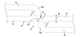
- the side view which shows the stent as the 1st Embodiment of this invention The perspective view of the principal part of the stent shown by FIG.
- the top view of the principal part of the stent shown by FIG. FIG. FIG. 5 is a VV cross-sectional view of FIG. 3.
- FIG. 1 shows a stent 10 as a first embodiment of the present invention.
- the stent 10 includes a substantially cylindrical peripheral wall portion 12 as a whole, and the peripheral wall portion 12 is formed by a linear body 14.
- FIG. 1 and FIG. 6 to be described later for the sake of clarity, the portion located on the front side of the paper surface of the stent 10 is illustrated, and the portion located on the back side of the paper surface is not illustrated.
- an axial direction means the left-right direction in FIG. 1 which is the center axis direction of the surrounding wall part 12 in principle.
- the linear body 14 is a longitudinal member extending in a substantially constant rectangular cross section, and may be formed of a biodegradable resin, a synthetic resin, or the like. It is formed of a metal having excellent biocompatibility such as an alloy or a Ni—Ti alloy (that is, a metal that is not toxic to living tissue and is bioinert).
- the linear body 14 extends in a spiral shape in the circumferential direction, and linear portions 16 extending in a predetermined length in the axial direction and curved portions 18 curved in a substantially semicircular arc shape are alternately and continuously. It is provided and has a wave shape that is folded back and forth in the axial direction with a predetermined amplitude.
- a curved portion that protrudes toward one side in the axial direction is a curved portion 18a, and the other side in the axial direction (right side in FIG. 1). ) are identified as curved portions 18b.
- the reciprocal amplitude of the linear body 14 is made substantially constant over the whole, and the linear body 14 exhibits a uniform wavy shape over almost the entire peripheral wall portion 12.
- the linear body 14 extends in a circumferential spiral while reciprocating in the axial direction, thereby forming a strip-like body extending in a circumferential spiral with a width corresponding to the amplitude of the linear body 14. Adjacent strips (curved portions 18a, 18b) are separated by a predetermined distance in the axial direction. The axial distance D (see FIG.
- the linear body 14 extends in a circumferential spiral shape while reciprocating with a predetermined amplitude in the axial direction, thereby forming the peripheral wall portion 12 having a substantially cylindrical shape as a whole.
- the peripheral wall portion 12 has a shape that is obtained by cutting both end portions of the cylinder along an inclined plane.
- the peripheral wall portion 12 can be obtained, for example, by cutting a substantially cylindrical metal member with a laser to form a linear body 14 having a predetermined shape.
- both ends of the linear body 14 in the length direction are disk-shaped portions 20 that are widened to a substantially disk shape as compared with the middle portion.
- FIG. 1 only the disk-shaped part 20 at one end of the linear body 14 is shown, but the same disk-shaped part 20 is provided at the other end not shown. ing.
- the linear body 14 is provided with a plurality of connecting portions 22 in the length direction.
- the connecting portion 22 is provided so as to connect the curved portion 18a and the curved portion 18b adjacent in the axial direction to each other, and is formed for each predetermined number of the curved portions 18a. Every five portions 22 are provided for the plurality of curved portions 18a. As a result, the plurality of connection portions 22 are evenly provided at substantially constant intervals in the length direction of the linear body 14.
- the weakened portion 24 is provided in the connecting portion 22 located in the middle portion of the linear body 14 in the length direction.
- the fragile portion 24 is a portion having a mechanical strength smaller than that of the linear body 14, and in the present embodiment, the entire connecting portion 22 located at the intermediate portion in the length direction is configured by the fragile portion 24. ing.
- the linear body 14 is provided between adjacent portions in the axial direction (curved portions 18a and 18b adjacent in the axial direction) and adjacent in the axial direction.
- the curved portions 18 a and 18 b are connected to each other by the weakened portion 24.
- the curved portions 18a and 18b adjacent in the axial direction are arranged so as to be shifted from each other in the circumferential direction, and the connecting direction of the curved portions 18a and 18b by the fragile portion 24 is inclined with respect to the axial direction.
- the connecting direction of the curved portions 18a and 18b by the fragile portion 24 is inclined with respect to the axial direction.
- the connecting direction may be parallel to the axial direction.
- the weakened portion 24 is formed by welding the curved portions 18a and 18b adjacent to each other in the axial direction of the linear body 14 with a laser.
- the fragile portion 24 can be easily formed by post-processing, and the fragile portion 24 can be formed in any shape and size by appropriately controlling the irradiation time and intensity of the laser.
- the breakage timing of the fragile portion 24 can be easily controlled.
- the dimension in the width direction orthogonal to the connecting direction of the curved portions 18a and 18b: w is smaller than the width dimension: W of the linear body 14, and this embodiment
- the dimension w in the width direction of the fragile portion 24 is 0.2 to 0.5 times the width dimension W of the linear body 14.
- the thickness dimension h of the fragile portion 24 is thinner than the thickness dimension H of the linear body 14, and is 0.2 times the thickness dimension of the linear body 14. It is supposed to be 0.5 times.
- the cross-sectional area of the fragile portion 24 (the area of the cross section extending perpendicular to the connecting direction) is linear. It is made smaller than the cross-sectional area (the area of the cross-section that extends perpendicular to the length direction) of the body 14.
- the cross-sectional area of the fragile portion 24 is 0.01 to 0.3 times the cross-sectional area of the linear body 14.
- connection part 22 located in the both ends of the length direction of the linear body 14 is made into the connection part 26 which does not have the weak part 24.
- FIG. 1 the connecting portion 26 is provided so as to connect the curved portions 18 a and 18 b adjacent in the axial direction, and the curved portions 18 a and 18 b are mutually connected by the connecting portion 26. It is connected to.
- the connecting portion 26 is thicker than the fragile portion 24 and has substantially the same thickness as the linear body 14, and is a portion having higher mechanical strength than the fragile portion 24.
- about one to ten connecting portions 26 are preferably formed at both ends of the linear body 14 in the length direction.
- connection part 26 may be integrally formed with the linear body 14 by laser processing etc., and may be formed later by laser welding etc. similarly to the weak part 24.
- both end portions of the linear body 14 in the length direction are regions that make one round in the circumferential direction from both ends of the linear body 14, and are located at the end of the linear body 14.
- One connecting portion 26 is formed so as to connect the bending portion 18a or the bending portion 18b to the adjacent bending portion 18b or the bending portion 18a in the axial direction.
- both ends in the length direction of the linear body 14 where the connecting portion 26 can be formed may be a region extending from a both ends in the length direction of the linear body 14 toward a central range, although not limitedly interpreted, for example, it refers to a region that makes three rounds in the circumferential direction from both ends of the linear body 14.
- both end portions in the length direction of the linear body 14 are portions where the connecting portions 26 that do not have the fragile portion 24 are formed in the linear body 14.
- the stent 10 having such a connection portion 22 is extrapolated to a balloon of a balloon catheter for stent expansion (not shown) and inserted into a narrowed portion of a body lumen (for example, a blood vessel or the like). Then, when the balloon of the balloon catheter for stent expansion is inflated, the stent 10 extrapolated to the balloon is expanded in diameter and brought into close contact with the blood vessel wall. Thereafter, the balloon is deflated and pulled out from the stent 10, whereby the stent 10 is placed in the stenosis portion of the blood vessel, and the occurrence of restenosis in the stenosis portion is prevented.
- a body lumen for example, a blood vessel or the like
- connection portion 22 When the stent 10 is expanded, as shown in FIG. 6, in the expanded stent 10, some of the axially adjacent curved portions 18 a and 18 b are held in a connected state by the connection portion 22. ing.
- the linear body 14 extends in a circumferential spiral while reciprocating with a constant amplitude in the axial direction, and therefore, the entire linear body 14 is stably deformed when the stent 10 is expanded. .
- the plurality of connecting portions 22 are provided at equal intervals, the increase in local rigidity due to the formation of the connecting portions 22 does not cause distortion in the stent 10. Therefore, the entire stent 10 is stably expanded and deformed by the balloon, and the entire stent 10 is brought into close contact with the inner surface of the blood vessel, and problems such as partial strong pressing are avoided.
- the shape followability of the stent 10 with respect to the pulsation and curvature of the blood vessel is enhanced, and stent fracture caused by placement in the bent portion of the blood vessel and the like is prevented. Can do. Furthermore, by improving the shape followability of the stent 10, it is possible to prevent the axial end of the stent 10 and the blood vessel wall from being strongly pressed when the blood vessel is deformed or when the stent 10 is placed in the bent portion of the blood vessel. In addition, it is possible to prevent blood vessel damage or inflammation caused by contact with the stent 10.
- the main body portion of the stent is composed of one linear body 14 extending in a spiral shape, it can be easily formed with a small number of parts, and all the fragile portions 24 are broken.
- the original function of the stent (such as a function of maintaining the inner diameter of the blood vessel in an expanded state) is effectively exhibited without being disassembled into a plurality of parts.
- the fragile portion 24 may be broken due to fatigue failure due to repeated action of stress due to, for example, pulsation of the blood vessel, or due to bending deformation of the blood vessel, etc. Then, when a large stress is applied, shear fracture or the like may be caused to cause the fracture. Further, it may be chemically broken due to decomposition or deterioration due to indwelling in a living body. In short, if the stent 10 is placed in a body lumen (blood vessel or the like) and the fragile portion 24 breaks preferentially with respect to the linear body 14, the mechanism by which the fragile portion 24 breaks is not particularly limited. .
- Such breakage of the fragile portion 24 due to the placement of the stent 10 is realized, for example, by making the cross-sectional area of the fragile portion 24 smaller than the cross-sectional area of the linear body 14. That is, when an external force due to pulsation of a blood vessel or the like acts on the stent 10, stress is concentrated on the fragile portion 24 having a smaller cross-sectional area than the linear body 14. It breaks before 14. In particular, since the cross-sectional area of the fragile portion 24 is 0.01 to 0.3 times the cross-sectional area of the linear body 14, the fragile portion 24 does not break when the stent 10 is expanded. While being held, the weakened portion 24 is easily broken by the placement of the stent 10 so that the flexibility of the stent 10 is ensured.
- the connecting portion 26 not having the fragile portion 24 is not broken, and the curved portions 18 a and 18 b adjacent in the axial direction are formed by the connecting portion 22. It is kept connected. Thereby, the shape stability of the stent 10 is ensured, and the stent 10 is in close contact with the blood vessel wall at least at both end portions. As a result, the displacement of the indwelling position of the stent 10 is prevented, and the narrowed portion of the blood vessel is stably held in the expanded state by the stent 10.
- connection part 26 is made larger than the cross-sectional area of the weak part 24, the weak part 24 fractures
- the connecting portion 26 is held in a state where the curved portions 18a and 18b are connected without breaking.
- both ends of the linear body 14 are the disk-shaped portions 20 that are widened, the disk-shaped portion 20 is in close contact with the blood vessel wall, so that the stent 10 The displacement of the indwelling position is prevented more effectively.
- a wide disk-shaped portion 20 having a disk shape is provided at both ends of the linear body 14. The problem that both ends of the body 14 are caught on the inner surface of the blood vessel to damage the blood vessel is also avoided.
- the disc-shaped portion 20 can also function as a contrast marker when the stent 10 is placed in a stenosis portion of a blood vessel. That is, the disk-shaped portion 20 that is wide and has a larger projected area than the linear body 14 in a side view and a plan view has excellent visibility during contrast imaging using X-rays or the like. By providing 20, it becomes easy to grasp the positions of both ends of the stent 10. As a result, it is possible to more accurately grasp whether the stent 10 is inserted into the intended indwelling site, whether the stent 10 is damaged or deformed, and the like by contrast imaging.
- FIG. 7 shows a main part of a stent as the second embodiment of the present invention.
- members and portions that are substantially the same as those in the first embodiment are denoted by the same reference numerals in the drawings, and the description thereof is omitted.
- the parts not shown are the same as those in the first embodiment.
- the proximity protrusions 30 are provided in the portions adjacent to each other in the axial direction in the linear body 14 (curved portions 18a and 18b adjacent in the axial direction).
- the proximity protrusion 30 is a protrusion that protrudes in the opposing direction between the opposing surfaces of the curved portions 18 a and 18 b adjacent in the axial direction, and is formed integrally with an intermediate portion in the length direction of the curved portion 18.
- a proximity protrusion 30a is formed on the curved portion 18a
- a proximity protrusion 30b is formed on the curved portion 18b that is adjacent to the curved portion 18a in the axial direction, and the protruding tips of these proximity protrusions 30a and 30b The surfaces are opposed to each other with a predetermined gap without contacting each other.
- Such a proximity projecting portion 30 is formed only at a site where the connection portion 22 to be described later is to be formed.
- the proximity projecting portion 30 projects in proximity to the plurality of curved portions 18a arranged in a circumferential spiral. Every five portions 30a are formed, and every five adjacent projecting portions 30b are formed with respect to the plurality of curved portions 18b that are also arranged in a circumferential spiral.
- connection part 22 is formed in the intermediate part of the length direction of the linear body 14 including the proximity
- the portions that are connected to each other and are adjacent in the axial direction in the linear body 14 are limited in relative displacement.
- the boundary between the linear body 14 and the proximity projecting portion 30 and the boundary between the proximity projecting portion 30 and the fragile portion 24 are indicated by two-dot chain lines.
- the stent of this embodiment provided with such a proximity projecting portion 30, it is possible to easily identify the portion where the fragile portion 24 is formed by laser welding, and the fragile portion 24 can be formed easily and reliably. Can be broken.
- the proximity protrusion 30a provided on the curved portion 18a and the proximity protrusion 30b provided on the curved portion 18b protrude in a direction approaching each other, the space between the proximity protrusions 30a and 30b is welded. Thus, the desired connection portion 22 can be obtained.
- FIG. 8 shows a main part of a stent as a third embodiment of the present invention. That is, in the stent of this embodiment, the surface of the linear body 14 is covered with the coating layer 40 as an adherend.
- the covering layer 40 is formed of a biodegradable resin (for example, polylactic acid, polycaprolactone, polyglycolic acid), and is formed so as to cover the entire surface of the linear body 14 made of a metal material. Has been.
- connection part 42 is formed in the part fixed by the laser etc. in the coating layer 40, and the curved part 18a and the curved part 18b adjacent to the axial direction of the linear body 14 are formed in the coating layer 40.
- the parts 42 are connected to each other.
- connection portion 42 is decomposed and absorbed by the stent indwelling in the body lumen, and is broken. Thereby, the weak part 44 which cancels
- the fragile portion 44 may be provided by a covering layer 40 that is integrally fixed to the linear body 14 in a composite structure like the stent of the present embodiment.
- the fragile portion 44 can be formed of a material different from the linear body 14 and the connecting portion 26 in terms of breaking strength, biodegradability, in vivo degradation, and the like, and the stent can be broken by being placed in the body lumen. It can be preferentially generated in the fragile portion 44.
- the fragile portion 44 is provided using the coating layer 40 formed of a biodegradable resin, the fragile portion 44 is ruptured stably by in vivo decomposition due to indwelling. Yes.
- the entire surface of the linear body 14 is covered with the coating layer 40, and the fragile portion 44 is formed by a part thereof.
- An adherend formed of a degradable resin may be fixed, and the fragile portion 44 may be formed as a whole.
- the connection part which has a weak part may be formed with the to-be-adhered body by adhere
- FIG. 9 shows a stent 46 as a fourth embodiment of the present invention.
- the stent 46 of the present embodiment has the same basic shape as the stent 10 of the first embodiment, and FIG. 9 shows a developed view in which the stent 46 is cut open at one place on the circumference.
- one end side of the stent 46 is illustrated, but the other end side is substantially rotationally symmetric in FIG.
- both end surfaces in the axial direction of the stent 10 are inclined with respect to the axial direction.
- both end surfaces in the axial direction of the stent 46 are in the axial direction. It is a substantially vertical surface, and the positions of the linear bodies 14, that is, the curved portions 18 a or 18 b are substantially aligned at both axial ends of the stent 46.
- the linear body 14 extends in the circumferential spiral while reciprocating in the axial direction with a substantially constant amplitude throughout, but in the stent 46 of the present embodiment, The axial reciprocation amplitude of the linear body 14 gradually changes at both axial end portions of the stent 46.
- the structure of the axial direction center part of the stent 46 of this embodiment is the same as the said 1st Embodiment.
- a widened portion 48 having a larger amplitude than the other portions on the circumference is provided at one place on the circumference of the linear body 14 at both axial ends of the stent 46.
- the widened portion 48 is shown at the top of the stent 46.
- the broken lines in FIG. 9 indicate both ends in the width direction of the reciprocal amplitude of the portion that is not the widened portion 48 of the linear body 14. That is, the broken line in FIG. 9 indicates a straight line connecting adjacent curved portions 18a and 18a or 18b and 18b in a portion that is not the widened portion 48 of the linear body 14. As shown in FIG. 9, the amplitude of the widened portion 48 exceeds the separation distance indicated by the broken line. In the stent 46, the widened portion 48 causes an angle of a helix extending continuously from both ends of the widened portion 48 ( ⁇ ) is changed.
- the reciprocating amplitude of the linear body 14 in this embodiment is substantially the same as the reciprocating amplitude in the axial central portion of the stent 46 even at the shortest portion located at the axial end of the stent 46.
- the reciprocal amplitude of the linear body 14 changes particularly in the widened portion 48, but the difference between the shortest amplitude and the longest amplitude of the linear body 14 in the stent 46 is 0. 5 mm or less.
- the inclination angle of the spiral with respect to the axial direction of the linear body 14 is substantially equal in the stent 10 of the first embodiment, but in the stent 46 of the present embodiment, the linear angle is linear.
- the inclination angle of the spiral with respect to the axial direction of the body 14 gradually changes at both end portions. Specifically, the inclination angle of the spiral of the linear body 14 is gradually increased toward the both ends in the axial direction of the stent 46 so as to approach the vertical (90 degrees).
- the inclination angle of the spiral of the linear body 14 is substantially vertical in the vicinity of the distal end in the axial direction of the stent 46.
- the inclination angle of the spiral of the linear body 14 does not need to reach the vertical even in the vicinity of the distal end in the axial direction of the stent 46, and may reach an inclination angle slightly exceeding the vertical.
- the inclination angle of the central portion of the stent 46 is desirably set in the range of 50 to 75 degrees.
- the region where the spiral inclination angle of the linear body 14 gradually changes may be set in one or more rounds in the circumferential direction of the stent 46. It is set at two or more rounds, and more preferably set to change at three or more rounds. Accordingly, it is possible to avoid a sudden change in the inclination angle of the spiral of the linear body 14, for example, by setting the change amount of the inclination angle per rotation to 5 degrees or less, and to deform and expand the stent 46 as a whole. Can be generated more smoothly.
- the inclination of the spiral is, for example, two points in the drawing in which the axial center of each of the linear portions 16 and 16 adjacent to each other in the linear body 14 is connected in the central portion perpendicular to the axis (vertical direction) in FIG.
- the helix indicated by the chain line indicates the helix angle, and is represented by a value of “(90 degrees) ⁇ (helix lead angle)”.
- the inclination angle of the helix is shown as an angle ⁇ formed with the central axis 50 extending in the axial direction (left-right direction in FIG. 9) indicated by the one-dot chain line.
- both end surfaces of the stent 46 are made close to perpendicular to the axial direction, and the positions of the curved portions 18a and 18b of the linear body 14 are substantially aligned at both ends. Therefore, even when the stent 46 passes through the bent portion of the blood vessel, it is possible to effectively prevent the axial end portion of the stent 46 from being locally lifted.
- the widening portion 48 is provided at both end portions of the linear body 14 to change the reciprocating amplitude so that the inclination angle with respect to the axial direction is vertical, so that the stent 46 can be effectively expanded and bent. That is, by providing the widened portion 48, the inclination angle of both end portions does not change abruptly.
- the stent 46 of this embodiment can exhibit a favorable expansion effect and bending effect. If the lid is covered and an excessively short amplitude portion is provided at the end portion of the stent, the expansion effect equivalent to that of the central portion may not be exhibited at the end portion of the stent. Further, if an excessively long amplitude portion is provided at the end portion of the stent, the flexibility is deteriorated, and there is a possibility that smooth deformation and expansion throughout the stent 46 are difficult to be exhibited.
- the weak part 24 showed the example formed by the laser welding of the linear body 14, when a weak part cuts out the linear body 14 from a cylindrical metal member with a laser, It may be integrally formed with the linear body 14 by cutting out similarly to the linear body 14. According to this, it is not necessary to perform post-processing such as laser welding in order to form the fragile portion, and the number of manufacturing steps can be reduced.
- the fragile portion is integrally formed with the linear body 14, the cross-sectional area of the connecting portion is formed to be smaller than that of the linear body 14, so that breakage at the connecting portion occurs preferentially.
- the fragile portion is not necessarily limited to one formed of a metal material, for example, a synthetic resin material having biodegradability (synthetic resin material that is decomposed in a body lumen after placement and discharged or absorbed) or
- the weak part may be formed by an adhesive or the like.
- the fragile portion is formed of a material different from that of the linear body 14, it is not essential that the cross-sectional area of the fragile portion is smaller than the cross-sectional area of the linear body 14. That is, the fragile part is formed of a material having a lower strength than the linear body 14 (a material that is more likely to break in the same shape), or is formed of a material that is easily decomposed or eroded in a living body.
- the cross-sectional area of the fragile portion may be the same as or larger than the cross-sectional area of the linear body 14 as long as it breaks before the linear body 14.
- the fragile portion in the indwelling state, the fragile portion needs to be preferentially broken with respect to the linear body, and the preferential breakage of the fragile portion is caused by the shape of the fragile portion and the linear body. It is not a problem whether it is realized by a difference in size (cross-sectional area) or a difference in forming material.
- the timing at which the fragile portion 24 breaks may be after placement of the stent 10 in a body lumen (blood vessel or the like), or may be when the stent 10 is expanded (during expansion and when expansion is completed). .
- the break timing of the fragile portion 24 can be controlled by adjusting the diameter expansion ratio (ratio of the diameter before expansion to the diameter after expansion) of the stent 10 in addition to the shape and size of the fragile portion 24. obtain.
- the number of formation of the weak parts 24 can be set arbitrarily.
- the weakened portions 24 do not necessarily have to be formed at every fifth of the plurality of curved portions 18a, and may be formed at any number or at all the curved portions 18.
- the fragile portions 24 are preferably formed at equal intervals with respect to the linear body 14 in order to ensure the shape stability of the stent 10 during expansion, but the linear body is not long in the length direction. In the case of having a uniform shape, it may be possible to improve the shape stability at the time of expansion by forming at different intervals.
- connection part is provided in the both ends of the linear body 14, the number of formation will not be specifically limited, One or two or more may be formed, and it is not formed. Also good. Further, similarly to the connecting portion, the connecting portion can be provided by integral formation with the linear body 14, post-forming by welding, or post-fixing of another member formed of a synthetic resin or the like.
- connection portion 22 is formed so as to connect the curved portion 18a and the curved portion 18b that are arranged adjacent to each other at a position closest to the axial direction.
- the position to be formed is not particularly limited as long as the portions (segments) adjacent in the axial direction in the body are connected to each other.
- the connecting portion may be provided so as to connect the linear portions 16 and 16 of the linear bodies 14 adjacent in the axial direction to each other, or the linear portion 16 and the curved portion 18 are mutually connected. It may be provided so that it may connect with. Furthermore, it can also be provided so as to connect the curved portion 18a and the curved portion 18b which are arranged with a large distance in the axial direction.
- the linear body 14 of the above-described embodiment has a structure that extends in a spiral shape in the circumferential direction while reciprocating in the axial direction by alternately connecting the linear portions 16 and the curved portions 18.
- the linear body may be extended in a circumferential spiral while being curved in a wavy shape (sin wave shape or the like), or may be bent in a zigzag and reciprocated in the axial direction while extending in a circumferential spiral.
- a linear shape or the like can also be employed.
- the linear body can be obtained by processing the wire into a shape extending in a spiral in the circumferential direction while reciprocating in the axial direction, in addition to cutting and forming a cylindrical metal member by laser processing.
- the scope of application of the present invention is not limited to a stent (balloon expandable stent) that is expanded by a balloon.
- a stent balloon expandable stent
- it is formed of a material that exhibits a shape memory effect, such as a Ni—Ti alloy.
- the present invention can also be applied to a stent having a self-expanding stent. Specifically, for example, a stent storing a shape in an expanded state is inserted into the protective sheath in a contracted state and restrained, and the protective sheath is removed from the stent at the indwelling position of the body lumen. The stent may be released from the restraint, and the stent may be restored to the expanded state based on the shape memory effect.
- Even in such a self-expanding stent by providing the connecting portion 22 that connects the linear bodies 14, shape stability during expansion and flexibility in the indwelling state can be realized at the same time. be
- the widened portion 48 is provided at one place on the circumference, but it may be provided at a plurality of places on the circumference.
- the stepwise change portion in the axial direction such as the widened portion 48 is provided to change the inclination of the spiral of the stent 46.
- the shape is not limited to this.
- the inclination of the spiral may be changed by slightly changing the reciprocal amplitude of the linear body 14 little by little. Even in such a shape, the uniform expansion effect of the stent can be sufficiently exerted.
- the stent may be gradually changed from the central portion toward both ends, or the reciprocating amplitude is changed in the range of the both ends, for example, four rounds in the circumferential direction of the stent. Also good.
Landscapes
- Health & Medical Sciences (AREA)
- Engineering & Computer Science (AREA)
- Biomedical Technology (AREA)
- Heart & Thoracic Surgery (AREA)
- Life Sciences & Earth Sciences (AREA)
- Cardiology (AREA)
- Oral & Maxillofacial Surgery (AREA)
- Transplantation (AREA)
- Physics & Mathematics (AREA)
- Vascular Medicine (AREA)
- Optics & Photonics (AREA)
- Animal Behavior & Ethology (AREA)
- General Health & Medical Sciences (AREA)
- Public Health (AREA)
- Veterinary Medicine (AREA)
- Media Introduction/Drainage Providing Device (AREA)
- Prostheses (AREA)
- Materials For Medical Uses (AREA)
Abstract
Description
Claims (11)
- 円筒状の周壁部を有していると共に、該周壁部が軸方向に所定の振幅で往復しながら周方向螺旋状に延びる線状体によって形成されたステントにおいて、
前記線状体における軸方向で隣接する部分を連結する接続部が形成されていると共に、体内管腔への留置によって破断されて該接続部による連結を解除する脆弱部を設けたことを特徴とするステント。 - 前記接続部の連結方向に直交して広がる断面の面積が、前記線状体の長さ方向に直交して広がる断面の面積よりも小さくされることにより前記脆弱部が構成されている請求項1に記載のステント。
- 前記線状体の軸方向での往復振幅が全体に亘って略一定とされている請求項1又は2に記載のステント。
- 前記線状体の軸方向に対する螺旋の傾斜角度が端部になるにつれて次第に大きくなって垂直に近づくようにされている請求項1又は2に記載のステント。
- 前記線状体の長さ方向で複数の前記接続部が形成されており、該線状体の長さ方向の中間部分に位置する該接続部には前記脆弱部が設けられている一方、該線状体の長さ方向の両端部分に位置する該接続部には該脆弱部が設けられておらず、体内管腔への留置後も連結状態に保持される請求項1~4の何れか1項に記載のステント。
- 複数の前記接続部が一定の間隔で設けられている請求項1~5の何れか1項に記載のステント。
- 前記線状体における軸方向で隣接する部分がレーザーで相互に溶接されることにより前記脆弱部が形成されている請求項1~6の何れか1項に記載のステント。
- 前記線状体における軸方向で隣接する部分に近接突出部が設けられており、該近接突出部がレーザーで相互に溶接されることにより前記脆弱部が形成されている請求項7に記載のステント。
- 前記線状体の長さ方向の両端が拡幅された円板状部とされている請求項1~8の何れか1項に記載のステント。
- 前記線状体に材質の異なる被着体が固着されており、該被着体によって前記脆弱部を有する前記接続部が形成されている請求項1~9の何れか1項に記載のステント。
- 前記被着体が生分解性樹脂で形成されている請求項10に記載のステント。
Priority Applications (5)
| Application Number | Priority Date | Filing Date | Title |
|---|---|---|---|
| JP2013541594A JP6218115B2 (ja) | 2011-11-02 | 2012-08-22 | ステント |
| US14/349,439 US9925075B2 (en) | 2011-11-02 | 2012-08-22 | Stent |
| SG11201401398XA SG11201401398XA (en) | 2011-11-02 | 2012-08-22 | Stent |
| CN201280053289.2A CN103906484B (zh) | 2011-11-02 | 2012-08-22 | 支架 |
| EP12846004.5A EP2774585B1 (en) | 2011-11-02 | 2012-08-22 | Stent |
Applications Claiming Priority (2)
| Application Number | Priority Date | Filing Date | Title |
|---|---|---|---|
| JP2011-241306 | 2011-11-02 | ||
| JP2011241306 | 2011-11-02 |
Publications (1)
| Publication Number | Publication Date |
|---|---|
| WO2013065218A1 true WO2013065218A1 (ja) | 2013-05-10 |
Family
ID=48191603
Family Applications (1)
| Application Number | Title | Priority Date | Filing Date |
|---|---|---|---|
| PCT/JP2012/005248 Ceased WO2013065218A1 (ja) | 2011-11-02 | 2012-08-22 | ステント |
Country Status (7)
| Country | Link |
|---|---|
| US (1) | US9925075B2 (ja) |
| EP (1) | EP2774585B1 (ja) |
| JP (1) | JP6218115B2 (ja) |
| CN (1) | CN103906484B (ja) |
| MY (1) | MY167271A (ja) |
| SG (1) | SG11201401398XA (ja) |
| WO (1) | WO2013065218A1 (ja) |
Cited By (5)
| Publication number | Priority date | Publication date | Assignee | Title |
|---|---|---|---|---|
| JP2016112388A (ja) * | 2014-12-16 | 2016-06-23 | ニプロ株式会社 | ステントデリバリカテーテル |
| WO2016104128A1 (ja) * | 2014-12-26 | 2016-06-30 | テルモ株式会社 | ステント |
| JPWO2016136375A1 (ja) * | 2015-02-27 | 2017-12-07 | テルモ株式会社 | ステントおよびステントの製造方法 |
| JP2018089162A (ja) * | 2016-12-05 | 2018-06-14 | ニプロ株式会社 | ステントデリバリカテーテルおよびステントデリバリカテーテルの製造方法 |
| EP3583925A1 (en) * | 2013-12-24 | 2019-12-25 | Nipro Corporation | Stent |
Families Citing this family (9)
| Publication number | Priority date | Publication date | Assignee | Title |
|---|---|---|---|---|
| US8382821B2 (en) | 1998-12-03 | 2013-02-26 | Medinol Ltd. | Helical hybrid stent |
| US20040267349A1 (en) | 2003-06-27 | 2004-12-30 | Kobi Richter | Amorphous metal alloy medical devices |
| US9155639B2 (en) * | 2009-04-22 | 2015-10-13 | Medinol Ltd. | Helical hybrid stent |
| JP6598152B2 (ja) * | 2015-09-18 | 2019-10-30 | テルモ株式会社 | ステント |
| CN106420127B (zh) * | 2016-10-15 | 2019-03-15 | 郑州大学第一附属医院 | 一种顺应食管蠕动性全贴合食管支架 |
| US11432950B2 (en) * | 2017-03-23 | 2022-09-06 | Nipro Corporation | Stent |
| CN109091275B (zh) * | 2018-08-24 | 2024-01-30 | 四川大学 | 生物可降解支架 |
| US12478488B2 (en) | 2020-02-19 | 2025-11-25 | Medinol Ltd. | Helical stent with enhanced crimping |
| CN113133856B (zh) * | 2021-04-20 | 2022-12-13 | 北京弘海微创科技有限公司 | 一种z型编织支架 |
Citations (8)
| Publication number | Priority date | Publication date | Assignee | Title |
|---|---|---|---|---|
| JPH04126558U (ja) * | 1991-04-30 | 1992-11-18 | 加藤発条株式会社 | 管状器官の拡張具 |
| JP2000316983A (ja) * | 1999-03-05 | 2000-11-21 | Terumo Corp | 生体留置用ステントおよび生体器官拡張器具 |
| JP2002052086A (ja) * | 2000-05-16 | 2002-02-19 | Cordis Corp | ステント |
| JP2008539889A (ja) * | 2005-05-05 | 2008-11-20 | ボストン サイエンティフィック リミテッド | 管状ステントおよびその製造方法 |
| JP2009082245A (ja) * | 2007-09-27 | 2009-04-23 | Terumo Corp | 生体内留置用ステントおよび生体器官拡張器具 |
| JP2010516340A (ja) * | 2007-01-18 | 2010-05-20 | メドトロニック ヴァスキュラー インコーポレイテッド | 可撓性を向上させたステントおよびこのステントの製造方法 |
| JP2011502636A (ja) | 2007-11-06 | 2011-01-27 | メドトロニック カルディオ ヴァスキュラー インコーポレイテッド | 改善された機械特性を有するステント |
| US20110218614A1 (en) * | 2010-03-02 | 2011-09-08 | Medtronic Vascular, Inc. | Stent With Sinusoidal Wave Form and Orthogonal End and Method for Making Same |
Family Cites Families (18)
| Publication number | Priority date | Publication date | Assignee | Title |
|---|---|---|---|---|
| US5913897A (en) * | 1993-09-16 | 1999-06-22 | Cordis Corporation | Endoprosthesis having multiple bridging junctions and procedure |
| US6042597A (en) * | 1998-10-23 | 2000-03-28 | Scimed Life Systems, Inc. | Helical stent design |
| US7029492B1 (en) * | 1999-03-05 | 2006-04-18 | Terumo Kabushiki Kaisha | Implanting stent and dilating device |
| US6409754B1 (en) * | 1999-07-02 | 2002-06-25 | Scimed Life Systems, Inc. | Flexible segmented stent |
| US20030045923A1 (en) * | 2001-08-31 | 2003-03-06 | Mehran Bashiri | Hybrid balloon expandable/self expanding stent |
| CN100591385C (zh) * | 2003-04-30 | 2010-02-24 | 尼普洛株式会社 | 对血管具有极好跟随能力的可延伸的柔软的支架 |
| US8157855B2 (en) * | 2003-12-05 | 2012-04-17 | Boston Scientific Scimed, Inc. | Detachable segment stent |
| US20060064155A1 (en) | 2004-09-01 | 2006-03-23 | Pst, Llc | Stent and method for manufacturing the stent |
| US7837726B2 (en) * | 2005-03-14 | 2010-11-23 | Abbott Laboratories | Visible endoprosthesis |
| JP2009502307A (ja) | 2005-07-25 | 2009-01-29 | インヴァテック エス.アール.エル. | 生体吸収可能部位を備えた内腔プロテーゼ |
| US20070100431A1 (en) * | 2005-11-03 | 2007-05-03 | Craig Bonsignore | Intraluminal medical device with strain concentrating bridge |
| WO2008028964A2 (en) * | 2006-09-07 | 2008-03-13 | Angiomed Gmbh & Co. Medizintechnik Kg | Helical implant having different ends |
| FR2911063B1 (fr) | 2007-01-09 | 2009-03-20 | Stentys S A S Soc Par Actions | Structure de pont ruptible pour un stent, et stent incluant de telles structures de pont. |
| EP1958598A1 (de) * | 2007-02-16 | 2008-08-20 | Universität Zürich | Wachstumsfähige, rohrförmige Stützprothese |
| US20080319534A1 (en) | 2007-06-22 | 2008-12-25 | Medtronic Vascular, Inc. | Stent With Improved Mechanical Properties |
| WO2009041664A1 (ja) * | 2007-09-27 | 2009-04-02 | Terumo Kabushiki Kaisha | ステントおよび生体器官拡張器具 |
| JP2009082244A (ja) * | 2007-09-27 | 2009-04-23 | Terumo Corp | 生体内留置用ステントおよび生体器官拡張器具 |
| EP2429453B1 (en) * | 2009-05-14 | 2021-01-27 | Orbusneich Medical Pte. Ltd | Self-expanding stent with polygon transition zone |
-
2012
- 2012-08-22 EP EP12846004.5A patent/EP2774585B1/en active Active
- 2012-08-22 SG SG11201401398XA patent/SG11201401398XA/en unknown
- 2012-08-22 WO PCT/JP2012/005248 patent/WO2013065218A1/ja not_active Ceased
- 2012-08-22 US US14/349,439 patent/US9925075B2/en active Active
- 2012-08-22 CN CN201280053289.2A patent/CN103906484B/zh active Active
- 2012-08-22 JP JP2013541594A patent/JP6218115B2/ja active Active
- 2012-08-22 MY MYPI2014001000A patent/MY167271A/en unknown
Patent Citations (8)
| Publication number | Priority date | Publication date | Assignee | Title |
|---|---|---|---|---|
| JPH04126558U (ja) * | 1991-04-30 | 1992-11-18 | 加藤発条株式会社 | 管状器官の拡張具 |
| JP2000316983A (ja) * | 1999-03-05 | 2000-11-21 | Terumo Corp | 生体留置用ステントおよび生体器官拡張器具 |
| JP2002052086A (ja) * | 2000-05-16 | 2002-02-19 | Cordis Corp | ステント |
| JP2008539889A (ja) * | 2005-05-05 | 2008-11-20 | ボストン サイエンティフィック リミテッド | 管状ステントおよびその製造方法 |
| JP2010516340A (ja) * | 2007-01-18 | 2010-05-20 | メドトロニック ヴァスキュラー インコーポレイテッド | 可撓性を向上させたステントおよびこのステントの製造方法 |
| JP2009082245A (ja) * | 2007-09-27 | 2009-04-23 | Terumo Corp | 生体内留置用ステントおよび生体器官拡張器具 |
| JP2011502636A (ja) | 2007-11-06 | 2011-01-27 | メドトロニック カルディオ ヴァスキュラー インコーポレイテッド | 改善された機械特性を有するステント |
| US20110218614A1 (en) * | 2010-03-02 | 2011-09-08 | Medtronic Vascular, Inc. | Stent With Sinusoidal Wave Form and Orthogonal End and Method for Making Same |
Non-Patent Citations (1)
| Title |
|---|
| See also references of EP2774585A4 * |
Cited By (6)
| Publication number | Priority date | Publication date | Assignee | Title |
|---|---|---|---|---|
| EP3583925A1 (en) * | 2013-12-24 | 2019-12-25 | Nipro Corporation | Stent |
| JP2016112388A (ja) * | 2014-12-16 | 2016-06-23 | ニプロ株式会社 | ステントデリバリカテーテル |
| WO2016104128A1 (ja) * | 2014-12-26 | 2016-06-30 | テルモ株式会社 | ステント |
| JPWO2016104128A1 (ja) * | 2014-12-26 | 2017-10-05 | テルモ株式会社 | ステント |
| JPWO2016136375A1 (ja) * | 2015-02-27 | 2017-12-07 | テルモ株式会社 | ステントおよびステントの製造方法 |
| JP2018089162A (ja) * | 2016-12-05 | 2018-06-14 | ニプロ株式会社 | ステントデリバリカテーテルおよびステントデリバリカテーテルの製造方法 |
Also Published As
| Publication number | Publication date |
|---|---|
| EP2774585A9 (en) | 2014-11-19 |
| MY167271A (en) | 2018-08-15 |
| EP2774585A1 (en) | 2014-09-10 |
| EP2774585A4 (en) | 2015-05-27 |
| JP6218115B2 (ja) | 2017-10-25 |
| US20140358218A1 (en) | 2014-12-04 |
| CN103906484B (zh) | 2016-05-25 |
| SG11201401398XA (en) | 2014-06-27 |
| JPWO2013065218A1 (ja) | 2015-04-02 |
| EP2774585B1 (en) | 2016-07-06 |
| US9925075B2 (en) | 2018-03-27 |
| CN103906484A (zh) | 2014-07-02 |
Similar Documents
| Publication | Publication Date | Title |
|---|---|---|
| JP6218115B2 (ja) | ステント | |
| JP4938666B2 (ja) | ステント及びステント製造方法 | |
| JP6479493B2 (ja) | 高柔軟性ステント | |
| JP2008511423A (ja) | ステント及びステント製造方法 | |
| JP2009538687A (ja) | クリンプ中に保持突起が形成されるステント | |
| JP7029578B1 (ja) | ステント | |
| US20100249901A1 (en) | Cylindrical stent | |
| KR20170112977A (ko) | 의료용 디바이스 | |
| JP6081948B2 (ja) | 柔軟性ステント | |
| JP7037128B2 (ja) | ステント | |
| CN101917941A (zh) | 带有弯曲支柱的医疗装置 | |
| JP4815057B2 (ja) | ステント | |
| JP2011502636A (ja) | 改善された機械特性を有するステント | |
| JP5796763B2 (ja) | ステント | |
| WO2016159162A1 (ja) | 高柔軟性ステント | |
| JP2008000193A (ja) | 自己拡張型ステント | |
| JP2011160915A (ja) | ステント及びその製造方法 | |
| JP2011072441A (ja) | 生体器官拡張器具 | |
| JP6734097B2 (ja) | 高柔軟性ステント | |
| WO2020059518A1 (ja) | スキャホールドシステムおよびスキャホールドの載置方法 | |
| JP2019170647A (ja) | ステント |
Legal Events
| Date | Code | Title | Description |
|---|---|---|---|
| 121 | Ep: the epo has been informed by wipo that ep was designated in this application |
Ref document number: 12846004 Country of ref document: EP Kind code of ref document: A1 |
|
| ENP | Entry into the national phase |
Ref document number: 2013541594 Country of ref document: JP Kind code of ref document: A |
|
| REEP | Request for entry into the european phase |
Ref document number: 2012846004 Country of ref document: EP |
|
| WWE | Wipo information: entry into national phase |
Ref document number: 2012846004 Country of ref document: EP |
|
| NENP | Non-entry into the national phase |
Ref country code: DE |
|
| WWE | Wipo information: entry into national phase |
Ref document number: 14349439 Country of ref document: US |