WO2013065227A1 - 電動車両用ハブ装置および電動自転車 - Google Patents
電動車両用ハブ装置および電動自転車 Download PDFInfo
- Publication number
- WO2013065227A1 WO2013065227A1 PCT/JP2012/005956 JP2012005956W WO2013065227A1 WO 2013065227 A1 WO2013065227 A1 WO 2013065227A1 JP 2012005956 W JP2012005956 W JP 2012005956W WO 2013065227 A1 WO2013065227 A1 WO 2013065227A1
- Authority
- WO
- WIPO (PCT)
- Prior art keywords
- hub
- gear
- internal
- case
- clutch
- Prior art date
- Legal status (The legal status is an assumption and is not a legal conclusion. Google has not performed a legal analysis and makes no representation as to the accuracy of the status listed.)
- Ceased
Links
Images








Classifications
-
- B—PERFORMING OPERATIONS; TRANSPORTING
- B62—LAND VEHICLES FOR TRAVELLING OTHERWISE THAN ON RAILS
- B62M—RIDER PROPULSION OF WHEELED VEHICLES OR SLEDGES; POWERED PROPULSION OF SLEDGES OR SINGLE-TRACK CYCLES; TRANSMISSIONS SPECIALLY ADAPTED FOR SUCH VEHICLES
- B62M6/00—Rider propulsion of wheeled vehicles with additional source of power, e.g. combustion engine or electric motor
- B62M6/40—Rider propelled cycles with auxiliary electric motor
- B62M6/60—Rider propelled cycles with auxiliary electric motor power-driven at axle parts
- B62M6/65—Rider propelled cycles with auxiliary electric motor power-driven at axle parts with axle and driving shaft arranged coaxially
-
- B—PERFORMING OPERATIONS; TRANSPORTING
- B62—LAND VEHICLES FOR TRAVELLING OTHERWISE THAN ON RAILS
- B62M—RIDER PROPULSION OF WHEELED VEHICLES OR SLEDGES; POWERED PROPULSION OF SLEDGES OR SINGLE-TRACK CYCLES; TRANSMISSIONS SPECIALLY ADAPTED FOR SUCH VEHICLES
- B62M11/00—Transmissions characterised by the use of interengaging toothed wheels or frictionally-engaging wheels
- B62M11/04—Transmissions characterised by the use of interengaging toothed wheels or frictionally-engaging wheels of changeable ratio
- B62M11/14—Transmissions characterised by the use of interengaging toothed wheels or frictionally-engaging wheels of changeable ratio with planetary gears
- B62M11/16—Transmissions characterised by the use of interengaging toothed wheels or frictionally-engaging wheels of changeable ratio with planetary gears built in, or adjacent to, the ground-wheel hub
Definitions
- the present invention relates to an electric vehicle hub device including a clutch in a hub case, an electric vehicle hub device not including a clutch, and an electric bicycle including such an electric vehicle hub device.
- the hub device 100 includes a pair of left and right fixed shafts 101 and 102 that are connected and fixed to both fork legs 119 of the front fork, a fixed member 103 provided on one fixed shaft 101, and the center of a front wheel (not shown). And a hub case 105 that is rotatable with respect to the fixing member 103.
- the motor 106 that rotates the hub case 105, the rotating member 107 that can rotate around the coaxial center of the hub case 105, and the rotation speed of the output shaft 108 of the motor 106 are reduced to rotate the rotation of the output shaft 108.
- a speed reducer 109 that transmits to the member 107 and a one-way clutch 110 are housed.
- the reduction gear 109 includes a sun gear 111 that is rotated by the output shaft 108 of the motor 106, an annular internal gear 112 that is provided on the rotating member 107, and a planetary gear that meshes with the sun gear 111 and the internal gear 112. 113.
- the one-way clutch 110 has a switching function of transmitting the rotation of the rotating member 107 from the rotating member 107 to the hub case 105 but not transmitting the rotation of the hub case 105 from the hub case 105 to the rotating member 107. That is, the one-way clutch 110 has a claw support ring 114, a ratchet claw 115 attached to the claw support ring 114, and an annular ratchet gear 116 provided inside the hub case 105.
- the rotating member 107 has an external screw shaft 117 that protrudes outward on the surface opposite to the internal gear 112.
- the claw support ring 114 is screwed onto the external screw shaft 117 and attached to the rotating member 107.
- the ratchet pawl 115 engages with the ratchet gear 116 in one rotation direction for transmitting the rotation of the rotating member 107 to the hub case 105, and does not engage with the ratchet gear 116 in a rotation direction opposite to the one rotation direction.
- the electric vehicle hub device 100 configured as described above is described in Patent Document 1 below.
- the one-way clutch 110 is provided as shown in FIG. 17 separately from the electric vehicle hub device 100 (hereinafter referred to as the clutch-equipped hub device 100) provided with the one-way clutch 110.
- the clutch-equipped hub device 100 There is a type of electric vehicle hub device 121 (hereinafter referred to as a clutch-free hub device 121).
- the internal gear 123 is connected and fixed inside the hub case 122 by a plurality of screws 124.
- the shape and dimensions of the hub case 105 and the internal gear 112 of the hub device with clutch 100 shown in FIG. 16 and the shape of the hub case 122 and the internal gear 123 of the hub device 121 without clutch shown in FIG. 16 and the hub case 105 and the internal gear 112 of the hub device 100 with a clutch shown in FIG. 16 are diverted to the hub case 122 and the internal gear 123 of the hub device 121 without a clutch shown in FIG. Was difficult.
- the present invention provides a hub device for an electric vehicle and an electric bicycle that can reduce the left-right width dimension of the hub case, and can divert the hub case and internal gear of the hub device with a clutch to a hub device without a clutch.
- the purpose is to do.
- a hub case rotatable with a wheel is provided at the center of the wheel,
- An electric motor that rotates the hub case in the hub case, an internal rotary member that is rotatable about the hub case and a coaxial center, and a reduction device that reduces the rotational speed of the output shaft of the motor and transmits the rotation of the output shaft to the internal rotary member
- a hub device for an electric vehicle with a clutch that houses a one-way clutch that transmits the rotation of the internal rotation member to the hub case but does not transmit the rotation of the hub case to the internal rotation member
- the internal rotating member has an annular internal gear
- the speed reducer has a sun gear that is rotated by the output shaft of the electric motor, and a planetary gear that meshes with the sun gear and the internal gear
- the one-way clutch has a first engagement member provided on the outer peripheral portion of the internal gear, and a second engagement member provided in the hub case, The second engagement member is disposed so as to surround
- the internal gear and the one-way clutch are arranged at substantially the same position in the rotational axis direction.
- the left-right width dimension of a hub case can be shortened.
- the hub case and internal gear of the hub device with a clutch can be used for the hub device without a clutch.
- the hub case rotates together with the wheel
- the second engagement member of the one-way clutch also rotates together with the hub case. Since the combined member does not engage with the second engagement member, the internal rotation member and the hub case are separated via the one-way clutch, and the rotation of the hub case is not transmitted to the internal rotation member. Thereby, an internal rotation member does not rotate and a rotational force is not provided to the output shaft of an electric motor from the outside. Therefore, when the electric vehicle is running with the electric motor stopped, it is possible to prevent the pedal from being heavyly depressed.
- the first engagement member is a ratchet claw
- the second engagement member is an annular ratchet gear
- the ratchet gear of the one-way clutch also rotates together with the hub case, but at this time, the ratchet pawl does not engage with the ratchet gear, so the inner rotating member and the hub case Is divided through a one-way clutch.
- the internal rotation member has a gear holder, An internal gear is removably attached to the gear holder.
- the fourth invention is an electric bicycle comprising the hub device for an electric vehicle with a clutch according to any one of the first to third inventions.
- the fifth aspect of the present invention is a hub apparatus for an electric vehicle without a clutch using an internal gear used in the hub apparatus for an electric vehicle with a clutch according to any one of the first to third aspects of the present invention.
- the internal gear is fitted and fixed in a cylindrical mounting member
- the attachment member is provided in the center of the wheel and is attached to the inside of the hub case that is rotatable together with the wheel, and is rotatable about the coaxial center integrally with the hub case.
- an electric motor that rotates the hub case and a reduction device that reduces the rotation speed of the output shaft of the electric motor and transmits the rotation of the output shaft to the hub case are housed.
- the reduction gear has a sun gear that rotates by an output shaft of an electric motor, and a planetary gear that meshes with the sun gear and an internal gear.
- the internal gear used for the electric vehicle hub device with the clutch is fitted into the attachment member of the electric vehicle hub device without the clutch, and the attachment member is attached inside the hub case.
- the internal gear is attached to the inside of the hub case via the attachment member, and the internal gear used in the electric vehicle hub device with a clutch can be diverted to the electric vehicle hub device without a clutch.
- the hub case is diverted from the hub case used in the hub device for an electric vehicle with a clutch according to any one of the first to third inventions. Is.
- the seventh aspect of the invention is an electric bicycle including the clutch-free electric vehicle hub device according to the fifth or sixth aspect of the invention.
- the electric vehicle hub device is miniaturized. Further, the hub case and the internal gear of the hub device with a clutch can be used for the hub device without a clutch, thereby reducing the number of parts and the cost.
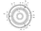
- FIG. Sectional view of the hub device without clutch of the electric bicycle
- FIG. Sectional view of the hub device without clutch of the electric bicycle
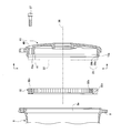
- FIG. The same sectional exploded view of the case lid, internal gear and mounting member of the hub device without clutch XX arrow view in FIG.
- the same figure shows the internal gear, mounting member and case lid of the hub device without clutch as seen from the inside of the hub case Sectional view of a conventional hub device with a clutch of an electric bicycle
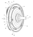
- 1 is an electric bicycle which is an example of an electric vehicle.
- the electric bicycle 1 includes a front wheel 2, a rear wheel 44, a pedal 43, and the like, and an electric vehicle hub device 3 is provided at the center of the front wheel 2.
- the electric vehicle hub device 3 is provided on a pair of left and right fixed shafts 5 and 6 that are connected and fixed to both fork legs 4 a of the front fork 4 and on either one of the left and right fixed shafts 5.
- a fixing member 7 and a hub case 8 rotatable with respect to the fixing member 7 are provided.
- the hub case 8 has a cylindrical case body 9 having an opening 9a on one side surface, and a case lid 10 attached to the case body 9 and closing the opening 9a.
- the case body 9 is rotatably supported on one fixed shaft 5 via one bearing member 11.
- the case lid 10 is rotatably supported by the other fixed shaft 6 via the other bearing member 12.
- the inner ends of the spokes 13 of the front wheel 2 are connected to the outer periphery of the case body 9.
- an electric motor 16 that rotates the hub case 8 around the axis 36, an internal rotating member 17 that is rotatable around the coaxial axis of the hub case 8, and an output shaft 18 of the electric motor 16 are decelerated and output.
- a reduction gear 19 that transmits the rotation of the shaft 18 to the internal rotation member 17 and a one-way clutch 20 are housed.
- the electric motor 16 is a brushless motor including a rotor 22 and a stator 23 in a housing 21, and the rotor 22 includes an output shaft 18.
- the internal rotation member 17 has an annular internal gear 26 and a disc-shaped gear holder 30 having a through hole at the center.
- the internal gear 26 is detachably attached to the gear holder 30 by a plurality of screws 46. Further, the gear holder 30 is rotatably supported by the other fixed shaft 6 via a bearing member 29.
- the reduction gear 19 includes a sun gear 25 that is rotated by the output shaft 18, and a plurality of planetary gears 27 that mesh with the sun gear 25 and the internal gear 26.
- the sun gear 25 is formed at the tip of the output shaft 18.
- the planetary gear 27 has a large-diameter gear portion and a small-diameter gear portion, and is supported by a support frame 28 provided in the housing 21 of the electric motor 16.
- the large diameter gear portion of the planetary gear 27 meshes with the sun gear 25, and the small diameter gear portion of the planetary gear 27 meshes with the internal gear 26.
- the planetary gear 27 rotates at a fixed position by the rotation of the sun gear 25, but does not revolve around the sun gear 25.
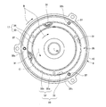
- the one-way clutch 20 has a switching function of transmitting the rotation of the internal rotation member 17 from the internal rotation member 17 to the hub case 8 but not transmitting the rotation of the hub case 8 from the hub case 8 to the internal rotation member 17. That is, as shown in FIGS. 2, 5, and 6, the one-way clutch 20 includes a plurality of ratchet claws 31 (an example of a first engagement member) provided on the outer peripheral portion of the internal gear 26, and the hub case 8. It has an annular ratchet gear 32 (an example of a second engagement member) provided inside, and a ring-shaped spring 33 cut at one place. As shown in FIG.
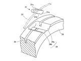
- the ratchet pawl 31 has an arcuate swollen bottom 31a at the base end, and a flat bottom 31b extending from the swollen bottom 31a to the tip.
- the ratchet claw 31 is formed with a slit-shaped cutout 31c that divides the claw 31 into left and right parts, except for the swollen bottom 31a.
- the internal gear 26 is made of iron and has an outer diameter A.
- a claw mounting portion 34 and a circumferential groove portion 35 are formed on the outer peripheral surface of the internal gear 26.
- the claw mounting portion 34 is formed at a plurality of locations in the circumferential direction, and has an arcuate recess 34a and a flat recess 34b continuous to the arcuate recess 34a.
- the ratchet claw 31 has a swollen bottom 31a rotatably fitted in an arcuate recess 34a of the claw mounting portion 34 with the flat bottom 31b facing the flat recess 34b.
- the spring 33 is fitted into the circumferential groove 35 of the internal gear 26 and the notch 31c of the ratchet pawl 31 to fasten the ratchet pawl 31 to the internal gear 26. As shown in FIG. 4, by tightening the spring 33, it is possible to prevent the ratchet pawl 31 from falling off from the pawl mounting portion 34, and the ratchet pawl 31 is biased in the direction in which the tip end stands.
- the ratchet gear 32 is a member having a tooth row 32 b on the inner peripheral surface of the ring body 32 a, and includes a plurality of screws 37 inside the case lid 10. It is fastened and attached, and is arranged so as to surround the internal gear 26 from the radially outer side. That is, as shown in FIG. 5, the internal gear 26 is rotatably inserted inside the ratchet gear 32.
- the ring body 32a is formed with screw holes 32c penetrating at a plurality of locations in the circumferential direction.
- the ratchet pawl 31 engages with the tooth row 32 b of the ratchet gear 32 in one rotation direction B that transmits the rotation of the internal rotation member 17 to the hub case 8. In the reverse rotation direction C, the tooth row 32b of the ratchet gear 32 is not engaged.
- the fixed shafts 5 and 6 and the output shaft 18 are disposed on the same shaft center 36, and the output shaft 18, the internal rotating member 17 and the hub case 8 are each around the shaft center 36. Rotate to.
- the case lid 10 has a cylindrical insertion portion 10 a that is inserted into the opening 9 a of the case body 9.
- a fitting portion 39 is formed over the entire circumference of the insertion portion 10 a, and the ratchet gear 32 is fitted into the fitting portion 39.
- the fitting portion 39 has a first receiving surface 39 a that receives the outer peripheral surface of the ratchet gear 32, and a second receiving surface 39 b that receives one end surface of the ratchet gear 32 that faces in the direction of the axis 36.
- the first receiving surface 39a and the second receiving surface 39b are orthogonal to each other.
- a plurality of rib portions 41 having through holes 40 penetrating inward and outward protrude from the inner peripheral surface radially inward.
- the screw 37 is inserted into the through hole 40 and screwed into the screw hole 32 c of the ratchet gear 32.
- the rib part 41 has the 3rd receiving surface 41a which receives the one end surface of the ratchet gear 32 in the edge part.
- the second receiving surface 39b and the third receiving surface 41a are formed in the same plane so as to be flush with each other.
- the internal gear 26 and the position of the one-way clutch 20 overlap in the radial direction, the internal gear 26 and the one-way clutch 20 are arranged at substantially the same position in the direction of the axis 36. Thereby, the left-right width dimension D of the hub case 8 can be shortened.
- the ratchet gear 32 is fitted into the fitting portion 39 of the case lid 10, and the first receiving surface 39 a of the fitting portion 39 is the outer peripheral surface of the ratchet gear 32. Therefore, the ratchet gear 32 is not displaced in the radial direction with respect to the case lid 10, and the axis of the ratchet gear 32 and the axis of the case lid 10 can be accurately aligned.
- the ratchet gear 32 since the second receiving surface 39 b of the fitting portion 39 and the third receiving surface 41 a of the rib portion 41 receive one end surface of the ratchet gear 32, the ratchet gear 32 has an axial center 36 with respect to the case lid 10.
- the ratchet gear 32 can be attached to the case lid 10 with high accuracy without tilting in the direction.
- the torque acting on the pedal 43 becomes a predetermined value or less, and the motor 16 stops.
- the hub case 8 rotates integrally with the hub case 8 in one rotational direction B, and the ratchet gear 32 of the one-way clutch 20 also rotates integrally with the hub case 8 in the rotational direction B.
- the ratchet pawl 31 is rotated by the tooth row 32b of the ratchet gear 32. Therefore, the internal rotation member 17 and the hub case 8 are separated by the one-way clutch 20, and the rotation of the hub case 8 is not transmitted to the internal rotation member 17.
- the internal rotation member 17 does not rotate, and no rotational force is applied to the output shaft 18 of the electric motor 16 from the outside. Therefore, when the electric bicycle 1 is running with the electric motor 16 stopped, it is possible to prevent the depression of the pedal 43 from becoming heavy.
- the hub device 3 for an electric vehicle shown in FIGS. 1 to 11 is a hub device 3 with a clutch provided with a one-way clutch 20.
- the internal gear 61 of the clutch-free hub device 60 is obtained by cutting the outer peripheral surface of the internal gear 26 (see FIG. 8) of the clutch-equipped hub device 3.
- a fitting portion 62 having an outer diameter A1 smaller than the outer diameter A of the internal gear 26 is formed.
- caulking holes 63 are formed at a plurality of locations in the circumferential direction.
- the internal gear 61 is attached to the case lid 10 of the hub case 8 via an attachment member 64.
- the attachment member 64 includes a cylindrical portion 64a and a disc portion 64b that extends radially outward from one end of the cylindrical portion 64a.
- the fitting portion 62 of the internal gear 61 is fitted into the cylindrical portion 64a of the mounting member 64, and the cylindrical portion 64a is caulked (cooked) with the hole 63 of the fitting portion 62.
- the internal gear 61 is connected and fixed to the mounting member 64.
- the disk portion 64b is formed with screw holes 64c penetrating at a plurality of locations in the circumferential direction.
- the disc part 64 b of the attachment member 64 is fitted in the fitting part 39 of the case lid 10.
- the outer diameter of the disc portion 64 b of the attachment member 64 is smaller than the inner diameter of the fitting portion 39 of the case lid 10, and the outer peripheral surface of the disc portion 64 b of the attachment member 64 and the case lid 10.
- a slight gap is formed in the radial direction between the first receiving surface 39a and the mounting member 64 fitted in the fitting portion 39 can be shifted in the radial direction by the gap.
- the screw 37 is inserted into the through hole 40 of the case lid 10 and is screwed into the screw hole 64c of the mounting member 64.
- the attachment member 64 is connected and fixed to the inside of the case lid 10 by a screw 37, and is rotatable around the coaxial center integrally with the hub case 8.
- the motor 16 for rotating the hub case 8 and the rotational speed of the output shaft 18 of the motor 16 are disposed in the hub case 8 of the hub device 60 without clutch.
- a speed reducer 19 that transmits the rotation of the output shaft 18 to the hub case 8 by decelerating the speed of the output shaft 18 is housed.
- the reduction gear 19 includes a sun gear 25 that is rotated by the output shaft 18, and a planetary gear 27 that meshes with the sun gear 25 and the internal gear 61.
- the hub case 8 (that is, the case main body 9 and the case lid 10) of the hub device with clutch 3 shown in FIG. 2 can be used as it is for the hub case 8 of the hub device 60 without clutch shown in FIG.
- the outer peripheral surface of the internal gear 26 of the hub device 3 with a clutch shown in FIG. 8 is cut to form a fitting portion 62 as shown in FIG. 13, and a hole portion 63 is formed in the fitting portion 62.
- the disc portion 64b of the attachment member 64 is fitted into the fitting portion 39 of the case lid 10, and the attachment member 64 is connected and fixed to the inside of the case lid 10 with the screw 37.
- the internal gear 61 is attached to the inside of the hub case 8 via the attachment member 64, so that the internal gear 26 (see FIG. 8) of the hub device 3 with a clutch is connected to the internal gear 61 ( (See FIG. 13).
- the number of types of parts and cost can be reduced.
- the internal gear 61 is integrated with the mounting member 64 in the case.
- the internal gear 61 can be accurately attached to the case lid 10 via the attachment member 64 without being inclined in the direction of the axis 36 with respect to the lid 10.
- the internal gears 26 and 61 are made of iron, heat is easily released to the outside, and heat dissipation is improved.
- the internal gears 26 and 61 may be made of metal other than iron.
- the clutch-equipped electric vehicle hub device 3 or the clutch-free electric vehicle hub device 60 is provided at the center of the front wheel 2 as shown in FIG. May be.
- the electric bicycle that is an example of the electric vehicle is provided with the clutch-equipped electric vehicle hub device 3 or the clutch-free electric vehicle hub device 60.
- the electric bicycle for example, an electric wheelchair or the like It is also possible to prepare for.
Landscapes
- Engineering & Computer Science (AREA)
- Chemical & Material Sciences (AREA)
- Combustion & Propulsion (AREA)
- Transportation (AREA)
- Mechanical Engineering (AREA)
- Retarders (AREA)
- Connection Of Motors, Electrical Generators, Mechanical Devices, And The Like (AREA)
- Arrangement Or Mounting Of Propulsion Units For Vehicles (AREA)
Abstract
ハブケース8内に、電動機16と、内部回転部材17と、電動機16の回転速度を減速して内部回転部材17に伝達する減速装置19と、内部回転部材17の回転をハブケース8に伝達するが、ハブケース8の回転を内部回転部材17に伝達しないワンウェイクラッチ20とが収納され、内部回転部材17は内歯歯車26を有し、減速装置19は、電動機16により回転される太陽歯車25と、太陽歯車25と内歯歯車26とに歯合する遊星歯車27とを有し、ワンウェイクラッチ20は、内歯歯車26の外周部に設けられたラチェット爪31と、ハブケース8内に設けられたラチェットギア32とを有し、ラチェットギア32は内歯歯車26を径方向外側から取囲むように配置されている。
Description
本発明は、ハブケース内にクラッチを備えた電動車両用ハブ装置とクラッチを備えていない電動車両用ハブ装置、および、このような電動車両用ハブ装置を備えた電動自転車に関する。
従来、この種の電動車両用ハブ装置としては、例えば図16に示すように、電動自転車に備えられるものがある。このハブ装置100は、前ホークの両ホーク足119に連結固定される左右一対の固定軸101,102と、片方の固定軸101に設けられた固定部材103と、前車輪(図示省略)の中心部に設けられ且つ固定部材103に対して回転自在なハブケース105とを有している。
ハブケース105内には、ハブケース105を回転させるモータ106と、ハブケース105と同軸心周りに回転自在な回転部材107と、モータ106の出力軸108の回転速度を減速して出力軸108の回転を回転部材107に伝達する減速装置109と、ワンウェイクラッチ110とが収納されている。
減速装置109は、モータ106の出力軸108によって回転する太陽歯車111と、回転部材107に設けられた円環状の内歯歯車112と、太陽歯車111と内歯歯車112とに歯合する遊星歯車113とを有している。
ワンウェイクラッチ110は、回転部材107の回転を回転部材107からハブケース105に伝達するが、ハブケース105の回転をハブケース105から回転部材107に伝達しない切換機能を有している。すなわち、ワンウェイクラッチ110は、爪支持リング114と、爪支持リング114に取付けられたラチェット爪115と、ハブケース105の内側に設けられた円環状のラチェットギア116とを有している。回転部材107は、内歯歯車112とは反対側の面に、外側方へ向って突出する外ねじ軸117を有している。爪支持リング114は外ねじ軸117に螺合されて回転部材107に取付けられている。ラチェット爪115は、回転部材107の回転をハブケース105に伝達する一方の回転方向においてラチェットギア116に係合し、上記一方の回転方向とは逆の回転方向においてラチェットギア116に係合しない。
尚、上記のような構成の電動車両用ハブ装置100については、下記特許文献1に記載されている。
また、上記図16に示すように、ワンウェイクラッチ110を備えた形式の電動車両用ハブ装置100(以下、クラッチ付きハブ装置100という)とは別に、図17に示すように、ワンウェイクラッチ110を備えていない形式の電動車両用ハブ装置121(以下、クラッチ無しハブ装置121という)がある。
このクラッチ無しハブ装置121では、内歯歯車123が複数のねじ124によってハブケース122の内側に連結固定されている。
しかしながら図16に示した従来のクラッチ付きハブ装置100では、内歯歯車112の位置とワンウェイクラッチ110の位置とが回転軸心118の方向においてずれているため、ハブケース105の左右幅寸法Dが増加し、電動車両用ハブ装置100が大型化するという問題がある。
また、従来においては、図16で示したクラッチ付きハブ装置100のハブケース105や内歯歯車112の形状および寸法と、図17で示したクラッチ無しハブ装置121のハブケース122や内歯歯車123の形状および寸法とが大幅に異なるため、図16で示したクラッチ付きハブ装置100のハブケース105や内歯歯車112を図17で示したクラッチ無しハブ装置121のハブケース122や内歯歯車123に流用することは困難であった。
本発明は、ハブケースの左右幅寸法を短縮することができ、また、クラッチ付きハブ装置のハブケースや内歯歯車をクラッチ無しハブ装置に流用することが可能な電動車両用ハブ装置および電動自転車を提供することを目的とする。
上記目的を達成するために、本第1発明は、車輪と共に回転自在なハブケースが車輪の中心部に設けられ、
ハブケース内に、ハブケースを回転させる電動機と、ハブケースと同軸心周りに回転自在な内部回転部材と、電動機の出力軸の回転速度を減速して出力軸の回転を内部回転部材に伝達する減速装置と、内部回転部材の回転をハブケースに伝達するが、ハブケースの回転を内部回転部材に伝達しないワンウェイクラッチとが収納されているクラッチ付き電動車両用ハブ装置であって、
内部回転部材は円環状の内歯歯車を有し、
減速装置は、電動機の出力軸によって回転する太陽歯車と、太陽歯車と内歯歯車とに歯合する遊星歯車とを有し、
ワンウェイクラッチは、内歯歯車の外周部に設けられた第1の係合部材と、ハブケース内に設けられた第2の係合部材とを有し、
第2の係合部材は内歯歯車を径方向外側から取り囲むように配置され、
第1の係合部材は、内部回転部材の回転をハブケースに伝達する一方の回転方向において第2の係合部材に係合し、上記一方の回転方向とは逆の回転方向において第2の係合部材に係合しないものである。
ハブケース内に、ハブケースを回転させる電動機と、ハブケースと同軸心周りに回転自在な内部回転部材と、電動機の出力軸の回転速度を減速して出力軸の回転を内部回転部材に伝達する減速装置と、内部回転部材の回転をハブケースに伝達するが、ハブケースの回転を内部回転部材に伝達しないワンウェイクラッチとが収納されているクラッチ付き電動車両用ハブ装置であって、
内部回転部材は円環状の内歯歯車を有し、
減速装置は、電動機の出力軸によって回転する太陽歯車と、太陽歯車と内歯歯車とに歯合する遊星歯車とを有し、
ワンウェイクラッチは、内歯歯車の外周部に設けられた第1の係合部材と、ハブケース内に設けられた第2の係合部材とを有し、
第2の係合部材は内歯歯車を径方向外側から取り囲むように配置され、
第1の係合部材は、内部回転部材の回転をハブケースに伝達する一方の回転方向において第2の係合部材に係合し、上記一方の回転方向とは逆の回転方向において第2の係合部材に係合しないものである。
これによると、内歯歯車の位置とワンウェイクラッチの位置とが径方向において重なるため、内歯歯車とワンウェイクラッチとが回転軸心方向においてほぼ同位置に配置される。これにより、ハブケースの左右幅寸法を短縮することができる。また、クラッチ付きハブ装置のハブケースや内歯歯車をクラッチ無しハブ装置に流用することができる。
電動機が駆動すると、出力軸の回転は減速装置で減速されて内部回転部材に伝達され、内部回転部材が回転する。この際、ワンウェイクラッチの第1の係合部材が第2の係合部材に係合するため、内部回転部材とハブケースとの間がワンウェイクラッチを介して繋がり、内部回転部材の回転がワンウェイクラッチを介してハブケースに伝達され、ハブケースが回転する。これにより、電動機から出力された回転力が車輪に付与される。
また、電動機が停止した状態で車輪が回転している場合、車輪と一体にハブケースが回転し、ハブケースと一体にワンウェイクラッチの第2の係合部材も回転するが、この際、第1の係合部材は第2の係合部材に係合しないので、内部回転部材とハブケースとの間がワンウェイクラッチを介して分断され、ハブケースの回転は内部回転部材に伝達されない。これにより、内部回転部材が回転せず、電動機の出力軸に外部側から回転力が付与されることはない。したがって、電動機が停止した状態で電動車両が走行している際、ペダルの踏み込みが重くなることを防止することができる。
本第2発明におけるクラッチ付き電動車両用ハブ装置は、第1の係合部材はラチェット爪であり、
第2の係合部材は円環状のラチェットギアであるものである。
第2の係合部材は円環状のラチェットギアであるものである。
これによると、電動機が駆動すると、ワンウェイクラッチのラチェット爪がラチェットギアに係合する。
また、電動機が停止した状態で車輪が回転している場合、ハブケースと一体にワンウェイクラッチのラチェットギアも回転するが、この際、ラチェット爪はラチェットギアに係合しないので、内部回転部材とハブケースとの間がワンウェイクラッチを介して分断される。
本第3発明におけるクラッチ付き電動車両用ハブ装置は、内部回転部材はギヤホルダーを有し、
内歯歯車がギヤホルダーに着脱自在に取付けられているものである。
内歯歯車がギヤホルダーに着脱自在に取付けられているものである。
本第4発明は、上記第1発明から第3発明のいずれか1項に記載のクラッチ付き電動車両用ハブ装置を備えたことを特徴とする電動自転車である。
本第5発明は、上記第1発明から第3発明のいずれか1項に記載のクラッチ付き電動車両用ハブ装置に使用される内歯歯車を流用したクラッチ無しの電動車両用ハブ装置であって、
内歯歯車は筒状の取付部材に嵌め込まれて連結固定され、
取付部材は、車輪の中心部に設けられて車輪と共に回転自在なハブケースの内側に取付けられて、ハブケースと一体に同軸心周りに回転自在であり、
ハブケース内に、ハブケースを回転させる電動機と、電動機の出力軸の回転速度を減速して出力軸の回転をハブケースに伝達する減速装置とが収納されており、
減速装置は、電動機の出力軸によって回転する太陽歯車と、太陽歯車と内歯歯車とに歯合する遊星歯車とを有しているものである。
内歯歯車は筒状の取付部材に嵌め込まれて連結固定され、
取付部材は、車輪の中心部に設けられて車輪と共に回転自在なハブケースの内側に取付けられて、ハブケースと一体に同軸心周りに回転自在であり、
ハブケース内に、ハブケースを回転させる電動機と、電動機の出力軸の回転速度を減速して出力軸の回転をハブケースに伝達する減速装置とが収納されており、
減速装置は、電動機の出力軸によって回転する太陽歯車と、太陽歯車と内歯歯車とに歯合する遊星歯車とを有しているものである。
これによると、クラッチ付き電動車両用ハブ装置に使用される内歯歯車をクラッチ無しの電動車両用ハブ装置の取付部材に嵌め込み、取付部材をハブケースの内側に取付ける。これにより、内歯歯車が取付部材を介してハブケースの内側に取付けられ、クラッチ付き電動車両用ハブ装置に使用される内歯歯車をクラッチ無しの電動車両用ハブ装置に流用することができる。
電動機が駆動すると、出力軸の回転は、太陽歯車から遊星歯車を介して内歯歯車に減速されて伝達され、さらに内歯歯車から取付部材を介してハブケースに伝えられる。これにより、ハブケースが回転し、電動機から出力された回転力が車輪に付与される。
本第6発明におけるクラッチ無しの電動車両用ハブ装置は、ハブケースは上記第1発明から第3発明のいずれか1項に記載のクラッチ付き電動車両用ハブ装置に使用されるハブケースを流用しているものである。
本第7発明は、上記第5発明又は第6発明に記載のクラッチ無しの電動車両用ハブ装置を備えたことを特徴とする電動自転車である。
以上のように本発明によると、ハブケースの左右幅寸法を短縮することができるため、電動車両用ハブ装置が小型化される。また、クラッチ付きハブ装置のハブケースや内歯歯車をクラッチ無しハブ装置に流用することができ、これにより、部品の種類数やコストを削減することができる。
以下、本発明における実施の形態を、図面を参照して説明する。
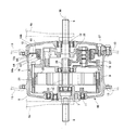
図1に示すように、1は電動車両の一例である電動自転車である。電動自転車1は前車輪2と後車輪44とペダル43等を備えており、前車輪2の中心部には電動車両用ハブ装置3が備えられている。図2に示すように、電動車両用ハブ装置3は、前ホーク4の両ホーク足4aに連結固定される左右一対の固定軸5,6と、左右いずれか一方の固定軸5に設けられた固定部材7と、固定部材7に対して回転自在なハブケース8とを有している。図3に示すように、ハブケース8は、一側面に開口部9aを有する円筒状のケース本体9と、ケース本体9に取付けられて開口部9aを閉じるケース蓋10とを有している。尚、図2に示すように、ケース本体9は、一方の軸受部材11を介して、回転自在に一方の固定軸5に支持されている。また、ケース蓋10は、他方の軸受部材12を介して、回転自在に他方の固定軸6に支持されている。前車輪2の各スポーク13の内端はケース本体9の外周部に連結されている。
ハブケース8内には、ハブケース8を軸心36周りに回転させる電動機16と、ハブケース8と同軸心周りに回転自在な内部回転部材17と、電動機16の出力軸18の回転速度を減速して出力軸18の回転を内部回転部材17に伝達する減速装置19と、ワンウェイクラッチ20とが収納されている。
電動機16は、ハウジング21内にローター22とステーター23とを備えたブラシレスモータであり、ローター22に出力軸18を備えている。
図2,図4に示すように、内部回転部材17は、円環状の内歯歯車26と、中心部に貫通孔を有する円板状のギヤホルダー30とを有している。内歯歯車26は複数のねじ46によってギヤホルダー30に着脱自在に取付けられている。また、ギヤホルダー30は軸受部材29を介して回転自在に他方の固定軸6に支持されている。
減速装置19は、出力軸18によって回転する太陽歯車25と、太陽歯車25と内歯歯車26とに歯合する複数の遊星歯車27とを有している。太陽歯車25は出力軸18の先端部に形成されている。
遊星歯車27は、大径歯車部と小径歯車部とを有し、電動機16のハウジング21に設けられた支持枠28によって支持されている。遊星歯車27の大径歯車部が太陽歯車25に歯合し、遊星歯車27の小径歯車部が内歯歯車26に歯合している。尚、太陽歯車25の回転により、遊星歯車27は、定位置で自転はするが、太陽歯車25の周囲を公転はしない。
ワンウェイクラッチ20は、内部回転部材17の回転を内部回転部材17からハブケース8に伝達するが、ハブケース8の回転をハブケース8から内部回転部材17に伝達しない切換機能を有している。すなわち、図2,図5,図6に示すように、ワンウェイクラッチ20は、内歯歯車26の外周部に設けられた複数のラチェット爪31(第1の係合部材の一例)と、ハブケース8内に設けられた円環状のラチェットギア32(第2の係合部材の一例)と、一箇所が切断されたリング状のスプリング33とを有している。図7に示すように、ラチェット爪31は、基端部に円弧状の膨み底部31aを有し、膨み底部31aから先端部わたって平坦底部31bを有している。また、ラチェット爪31には、膨み底部31aを除いて、爪31を左右に二分するスリット状の切欠部31cが形成されている。
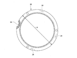
図8,図9に示すように、内歯歯車26は、鉄製であり、外径Aを有している。内歯歯車26の外周面には爪取付部34と周溝部35とが形成されている。爪取付部34は、周方向において複数箇所に形成されており、図7に示すように、円弧状凹部34aと、円弧状凹部34aに連続する平坦凹部34bとを有している。ラチェット爪31は、平坦底部31bが平坦凹部34bに対向した状態で、膨み底部31aが爪取付部34の円弧状凹部34aに回動自在に嵌められている。
スプリング33は、内歯歯車26の周溝部35とラチェット爪31の切欠部31cとに嵌め込まれて、ラチェット爪31を内歯歯車26に締付けている。図4に示すように、スプリング33の締付けにより、ラチェット爪31が爪取付部34から脱落するのを防止できると共に、ラチェット爪31の先端が起立する方向に付勢される。
図2,図3,図6,図10に示すように、ラチェットギア32は、リング体32aの内周面に歯列32bを有する部材であって、ケース蓋10の内側に複数のねじ37で締結されて取付けられており、内歯歯車26を径方向外側から取り囲むように配置されている。すなわち、図5に示すように、内歯歯車26は、ラチェットギア32の内側に、回転自在に挿入されている。また、リング体32aには、ねじ孔32cが周方向における複数箇所に貫通して形成されている。
図6に示すように、ラチェット爪31は、内部回転部材17の回転をハブケース8に伝達する一方の回転方向Bにおいてラチェットギア32の歯列32bに係合し、上記一方の回転方向Bとは逆の回転方向Cにおいてラチェットギア32の歯列32bに係合しない。
尚、図2に示すように、固定軸5,6と出力軸18とは同一軸心36上に配置されており、出力軸18と内部回転部材17とハブケース8とはそれぞれ、軸心36周りに回転する。
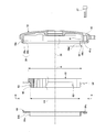
図3,図11に示すように、ケース蓋10はケース本体9の開口部9aに挿入される円筒状の挿入部10aを有している。挿入部10aの内周には嵌合部39が全周にわたり形成されており、ラチェットギア32は嵌合部39に嵌め込まれている。嵌合部39は、ラチェットギア32の外周面を受ける第1受け面39aと、軸心36の方向において対向するラチェットギア32の一端面を受ける第2受け面39bとを有している。尚、第1受け面39aと第2受け面39bとは直交している。
また、ケース蓋10の内側には、内外方に貫通した貫通孔40を備えた複数のリブ部41が内周面から径方向内側に突出している。ねじ37は、貫通孔40に挿通されて、ラチェットギア32のねじ孔32cに螺合されている。リブ部41は、端部に、ラチェットギア32の一端面を受ける第3受け面41aを有している。尚、第2受け面39bと第3受け面41aとは、面一になるように、同一面内に形成されている。
以下、上記構成における作用を説明する。
図2に示すように、内歯歯車26の位置とワンウェイクラッチ20の位置とが径方向において重なるため、内歯歯車26とワンウェイクラッチ20とが軸心36の方向においてほぼ同位置に配置され、これにより、ハブケース8の左右幅寸法Dを短縮することができる。
また、図2,図3の仮想線で示すように、ラチェットギア32はケース蓋10の嵌合部39に嵌め込まれており、嵌合部39の第1受け面39aがラチェットギア32の外周面を受けているため、ラチェットギア32がケース蓋10に対して径方向へずれることはなく、ラチェットギア32の軸心とケース蓋10の軸心とを正確に合わせることができる。
さらに、嵌合部39の第2受け面39bとリブ部41の第3受け面41aとがラチェットギア32の一端面を受けているため、ケース蓋10に対してラチェットギア32が軸心36の方向へ傾いてしまうことはなく、ラチェットギア32をケース蓋10に精度良く取付けることができる。
自転車1を走行させている際、ペダル43に作用するトルクが所定値を超えると、電動機16が駆動して出力軸18が回転し、太陽歯車25と各遊星歯車27とが回転し、回転速度が減速された状態で、図6に示すように、内部回転部材17が一方の回転方向Bに回転する。
この際、ワンウェイクラッチ20のラチェット爪31がラチェットギア32の歯列32bに係合するため、内部回転部材17とハブケース8との間がワンウェイクラッチ20を介して繋がり、内部回転部材17の回転がワンウェイクラッチ20を介してハブケース8に伝達され、ハブケース8が一方の回転方向Bに回転する。これにより、電動機16から出力された回転力が前車輪2に付与される。
また、電動自転車1を走行させている際、前車輪2と後車輪44とが回転している状態で、ペダル43に作用するトルクが所定値以下となり、電動機16が停止した場合、前車輪2と一体にハブケース8が一方の回転方向Bに回転し、ハブケース8と一体にワンウェイクラッチ20のラチェットギア32も回転方向Bに回転するが、この際、ラチェット爪31がラチェットギア32の歯列32bに係合しないので、内部回転部材17とハブケース8との間がワンウェイクラッチ20を介して分断され、ハブケース8の回転は内部回転部材17に伝達されない。これにより、内部回転部材17が回転せず、電動機16の出力軸18に外部側から回転力が付与されることはない。したがって、電動機16が停止した状態で電動自転車1が走行している際、ペダル43の踏み込みが重くなることを防止することができる。
尚、上記図1~図11に示した電動車両用ハブ装置3はワンウェイクラッチ20を備えたクラッチ付きハブ装置3である。
次に、ワンウェイクラッチ20を備えていないクラッチ無しハブ装置60の構成を、図12~図15を参照しながら説明する。尚、先述したクラッチ付きハブ装置3と同一の部材については同じ番号を付記して説明を省略する。
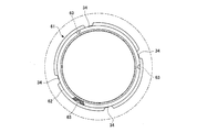
図13,図14に示すように、クラッチ無しハブ装置60の内歯歯車61は、クラッチ付きハブ装置3の内歯歯車26(図8参照)の外周面を切削加工して、外周面に、内歯歯車26の外径Aよりも小さい外径A1の嵌込部62を形成している。内歯歯車61の嵌込部62の外周面には、かしめ用の孔部63が周方向における複数箇所に形成されている。
図12,図13,図15に示すように、内歯歯車61は取付部材64を介してハブケース8のケース蓋10に取付けられている。取付部材64は、円筒部64aと、円筒部64aの一端から径方向外側に拡がる円板部64bとを有している。内歯歯車61の嵌込部62は取付部材64の円筒部64aに嵌め込まれており、円筒部64aを嵌込部62の孔部63とかしめる(コーキングする)ことによって、図12に示すように、内歯歯車61が取付部材64に連結固定される。また、円板部64bには、ねじ孔64cが周方向における複数箇所に貫通して形成されている。
図12に示すように、取付部材64の円板部64bは、ケース蓋10の嵌合部39に嵌め込まれている。尚、図13に示すように、取付部材64の円板部64bの外径はケース蓋10の嵌合部39の内径よりも小さく、取付部材64の円板部64bの外周面とケース蓋10の第1受け面39aとの間には、径方向において僅かな間隙が形成されており、嵌合部39に嵌め込まれた取付部材64は上記間隙分だけ径方向に変移可能である。
また、ねじ37は、ケース蓋10の貫通孔40に挿通され、取付部材64のねじ孔64cにねじ込まれている。取付部材64は、ねじ37によってケース蓋10の内側に連結固定され、ハブケース8と一体に同軸心周りに回転自在である。
尚、先述したクラッチ付きハブ装置3と同様に、図12に示すように、クラッチ無しハブ装置60のハブケース8内には、ハブケース8を回転させる電動機16と、電動機16の出力軸18の回転速度を減速して出力軸18の回転をハブケース8に伝達する減速装置19などが収納されている。減速装置19は、出力軸18によって回転する太陽歯車25と、太陽歯車25と内歯歯車61とに歯合する遊星歯車27とを有している。
以下、上記構成における作用を説明する。
図2で示したクラッチ付きハブ装置3のハブケース8(すなわちケース本体9とケース蓋10)を、そのまま、図12で示したクラッチ無しハブ装置60のハブケース8に流用することができる。
また、図8で示したクラッチ付きハブ装置3の内歯歯車26の外周面を切削加工して、図13に示すように、嵌込部62を形成し、嵌込部62に孔部63を形成し、内歯歯車61の嵌込部62を取付部材64の円筒部64aに嵌め込み、円筒部64aを嵌込部62の孔部63とかしめることによって、図12に示すように、内歯歯車61が取付部材64に一体的に連結固定される。
その後、取付部材64の円板部64bをケース蓋10の嵌合部39に嵌め込み、ねじ37によって取付部材64をケース蓋10の内側に連結固定する。これにより、内歯歯車61が取付部材64を介してハブケース8の内側に取付けられるため、クラッチ付きハブ装置3の内歯歯車26(図8参照)をクラッチ無しハブ装置60の内歯歯車61(図13参照)として流用することができる。これにより、部品の種類数やコストを削減することができる。
尚、図12,図13の仮想線で示すように、取付部材64の円板部64bをケース蓋10の嵌合部39に嵌め込んだ際、径方向において僅かな間隙が円板部64bの外周面とケース蓋10の第1受け面39aとの間に形成されるため、取付部材64を上記間隙分だけ径方向に変移させて、内歯歯車61の軸心とケース蓋10の軸心とを正確に合わせることができる。
さらに、嵌合部39の第2受け面39bとリブ部41の第3受け面41aとが取付部材64の円板部64bを受けているため、取付部材64と一体に内歯歯車61がケース蓋10に対して軸心36の方向へ傾いてしまうことはなく、取付部材64を介して内歯歯車61をケース蓋10に精度良く取付けることができる。
電動機16が駆動して出力軸18が回転すると、太陽歯車25と各遊星歯車27とが回転し、回転速度が減速された状態で、回転力が遊星歯車27から内歯歯車61に伝達され、内歯歯車61と一体にハブケース8が回転し、これにより、電動機16から出力された回転力が前車輪2に付与される。
また、内歯歯車26,61は鉄製であるため、外部へ熱を放出し易く、放熱性が向上する。尚、内歯歯車26,61は鉄製以外の金属製であってもよい。
上記実施の形態では、図1に示すように、クラッチ付き電動車両用ハブ装置3又はクラッチ無し電動車両用ハブ装置60を前車輪2の中心部に設けたが、後車輪44の中心部に設けてもよい。
上記実施の形態では、電動車両の一例である電動自転車に、クラッチ付き電動車両用ハブ装置3又はクラッチ無し電動車両用ハブ装置60を備えているが、電動自転車以外に、例えば電動式の車椅子等に備えることも可能である。
Claims (7)
- 車輪と共に回転自在なハブケースが車輪の中心部に設けられ、
ハブケース内に、ハブケースを回転させる電動機と、ハブケースと同軸心周りに回転自在な内部回転部材と、電動機の出力軸の回転速度を減速して出力軸の回転を内部回転部材に伝達する減速装置と、内部回転部材の回転をハブケースに伝達するが、ハブケースの回転を内部回転部材に伝達しないワンウェイクラッチとが収納されているクラッチ付き電動車両用ハブ装置であって、
内部回転部材は円環状の内歯歯車を有し、
減速装置は、電動機の出力軸によって回転する太陽歯車と、太陽歯車と内歯歯車とに歯合する遊星歯車とを有し、
ワンウェイクラッチは、内歯歯車の外周部に設けられた第1の係合部材と、ハブケース内に設けられた第2の係合部材とを有し、
第2の係合部材は内歯歯車を径方向外側から取り囲むように配置され、
第1の係合部材は、内部回転部材の回転をハブケースに伝達する一方の回転方向において第2の係合部材に係合し、上記一方の回転方向とは逆の回転方向において第2の係合部材に係合しないことを特徴とするクラッチ付き電動車両用ハブ装置。 - 第1の係合部材はラチェット爪であり、
第2の係合部材は円環状のラチェットギアであることを特徴とする請求項1記載のクラッチ付き電動車両用ハブ装置。 - 内部回転部材はギヤホルダーを有し、
内歯歯車がギヤホルダーに着脱自在に取付けられていることを特徴とする請求項1又は請求項2記載のクラッチ付き電動車両用ハブ装置。 - 上記請求項1から請求項3のいずれか1項に記載のクラッチ付き電動車両用ハブ装置を備えたことを特徴とする電動自転車。
- 上記請求項1から請求項3のいずれか1項に記載のクラッチ付き電動車両用ハブ装置に使用される内歯歯車を流用したクラッチ無しの電動車両用ハブ装置であって、
内歯歯車は筒状の取付部材に嵌め込まれて連結固定され、
取付部材は、車輪の中心部に設けられて車輪と共に回転自在なハブケースの内側に取付けられて、ハブケースと一体に同軸心周りに回転自在であり、
ハブケース内に、ハブケースを回転させる電動機と、電動機の出力軸の回転速度を減速して出力軸の回転をハブケースに伝達する減速装置とが収納されており、
減速装置は、電動機の出力軸によって回転する太陽歯車と、太陽歯車と内歯歯車とに歯合する遊星歯車とを有していることを特徴とするクラッチ無しの電動車両用ハブ装置。 - ハブケースは上記請求項1から請求項3のいずれか1項に記載のクラッチ付き電動車両用ハブ装置に使用されるハブケースを流用していることを特徴とする請求項5記載のクラッチ無しの電動車両用ハブ装置。
- 上記請求項5又は請求項6に記載のクラッチ無しの電動車両用ハブ装置を備えたことを特徴とする電動自転車。
Priority Applications (2)
| Application Number | Priority Date | Filing Date | Title |
|---|---|---|---|
| EP12845572.2A EP2774835B1 (en) | 2011-10-31 | 2012-09-20 | Electric vehicle hub device, and electric bicycle |
| CN201280053300.5A CN103906678B (zh) | 2011-10-31 | 2012-09-20 | 电动车用轮轴装置及电动自行车 |
Applications Claiming Priority (2)
| Application Number | Priority Date | Filing Date | Title |
|---|---|---|---|
| JP2011238097A JP5279882B2 (ja) | 2011-10-31 | 2011-10-31 | 電動車両用ハブ装置および電動自転車 |
| JP2011-238097 | 2011-10-31 |
Publications (1)
| Publication Number | Publication Date |
|---|---|
| WO2013065227A1 true WO2013065227A1 (ja) | 2013-05-10 |
Family
ID=48191610
Family Applications (1)
| Application Number | Title | Priority Date | Filing Date |
|---|---|---|---|
| PCT/JP2012/005956 Ceased WO2013065227A1 (ja) | 2011-10-31 | 2012-09-20 | 電動車両用ハブ装置および電動自転車 |
Country Status (4)
| Country | Link |
|---|---|
| EP (1) | EP2774835B1 (ja) |
| JP (1) | JP5279882B2 (ja) |
| CN (1) | CN103906678B (ja) |
| WO (1) | WO2013065227A1 (ja) |
Cited By (1)
| Publication number | Priority date | Publication date | Assignee | Title |
|---|---|---|---|---|
| CN107651094A (zh) * | 2016-11-07 | 2018-02-02 | 太仓市悦博电动科技有限公司 | 中置电动自行车的倒刹分离装置及电动自行车 |
Families Citing this family (4)
| Publication number | Priority date | Publication date | Assignee | Title |
|---|---|---|---|---|
| KR101762447B1 (ko) | 2011-08-09 | 2017-07-27 | 엘지이노텍 주식회사 | 트랙션 모터 모듈 |
| CN106364622B (zh) * | 2016-10-18 | 2022-05-24 | 无锡富乐力科技有限公司 | 一种用于自行车的一体化电助力装置 |
| CN107276348A (zh) * | 2017-06-09 | 2017-10-20 | 浙江绿源电动车有限公司 | 电机结构及电动自行车 |
| WO2020085213A1 (ja) * | 2018-10-23 | 2020-04-30 | ソニー株式会社 | インホイールモータ及び電動輪 |
Citations (1)
| Publication number | Priority date | Publication date | Assignee | Title |
|---|---|---|---|---|
| JP2009012627A (ja) | 2007-07-05 | 2009-01-22 | Sanyo Electric Co Ltd | 電動車輪用ハブ及び該ハブを具えた乗物 |
Family Cites Families (4)
| Publication number | Priority date | Publication date | Assignee | Title |
|---|---|---|---|---|
| JP3939862B2 (ja) * | 1998-08-18 | 2007-07-04 | ヤマハ発動機株式会社 | 電動自転車用モータ駆動ユニット |
| EP1298051A3 (en) * | 2001-09-28 | 2005-12-14 | Kabushiki Kaisha Moric | Electrically assisted unit |
| CN201312196Y (zh) * | 2008-11-20 | 2009-09-16 | 无锡罗特电机有限公司 | 电动车轮毂 |
| US8376110B2 (en) * | 2010-01-08 | 2013-02-19 | Shimano Inc. | Bicycle hub assembly |
-
2011
- 2011-10-31 JP JP2011238097A patent/JP5279882B2/ja active Active
-
2012
- 2012-09-20 WO PCT/JP2012/005956 patent/WO2013065227A1/ja not_active Ceased
- 2012-09-20 EP EP12845572.2A patent/EP2774835B1/en active Active
- 2012-09-20 CN CN201280053300.5A patent/CN103906678B/zh active Active
Patent Citations (1)
| Publication number | Priority date | Publication date | Assignee | Title |
|---|---|---|---|---|
| JP2009012627A (ja) | 2007-07-05 | 2009-01-22 | Sanyo Electric Co Ltd | 電動車輪用ハブ及び該ハブを具えた乗物 |
Cited By (2)
| Publication number | Priority date | Publication date | Assignee | Title |
|---|---|---|---|---|
| CN107651094A (zh) * | 2016-11-07 | 2018-02-02 | 太仓市悦博电动科技有限公司 | 中置电动自行车的倒刹分离装置及电动自行车 |
| CN107651094B (zh) * | 2016-11-07 | 2023-05-12 | 太仓市悦博电动科技有限公司 | 中置电动自行车的倒刹分离装置及电动自行车 |
Also Published As
| Publication number | Publication date |
|---|---|
| JP2013095210A (ja) | 2013-05-20 |
| CN103906678B (zh) | 2016-10-26 |
| EP2774835A4 (en) | 2015-04-15 |
| JP5279882B2 (ja) | 2013-09-04 |
| CN103906678A (zh) | 2014-07-02 |
| EP2774835A1 (en) | 2014-09-10 |
| EP2774835B1 (en) | 2017-12-27 |
Similar Documents
| Publication | Publication Date | Title |
|---|---|---|
| US10443688B2 (en) | Driving device having motor and gearbox | |
| US8360927B2 (en) | Vehicle power transmission device | |
| US8598755B2 (en) | Electric rotary actuator | |
| JP5279882B2 (ja) | 電動車両用ハブ装置および電動自転車 | |
| JP2009012627A (ja) | 電動車輪用ハブ及び該ハブを具えた乗物 | |
| JP2014084019A (ja) | 駆動ユニット | |
| TW201226261A (en) | Internal motorized bicycle hub | |
| JP4959837B1 (ja) | 電動用ハブ装置および電動自転車 | |
| JP5084977B1 (ja) | 電動用ハブ装置および電動自転車 | |
| US20180342927A1 (en) | Drive apparatus | |
| CN108702065A (zh) | 电动车辆驱动装置 | |
| US20090266189A1 (en) | Clutch control system | |
| JP5480845B2 (ja) | 遊星歯車機構 | |
| JP6006137B2 (ja) | 駆動装置 | |
| WO2012137427A1 (ja) | ハブユニットおよび電動自転車 | |
| JP4902727B2 (ja) | ディファレンシャル装置 | |
| JP5300830B2 (ja) | モータ内蔵自転車用ハブ | |
| KR101870441B1 (ko) | 전기 자전거 모터 변속기의 위성기어모듈 | |
| JP2011179569A5 (ja) | ||
| JP2010127838A (ja) | 取付位置調整装置及び方法 | |
| JPH10252861A (ja) | 差動装置の差動ケース構造 | |
| JP5317348B2 (ja) | トルククラッチ | |
| JP6179704B2 (ja) | 電動用ハブ装置および電動自転車 | |
| JPH10259863A (ja) | 差動装置 | |
| JP2010210004A (ja) | 回転部材への歯車の固定構造 |
Legal Events
| Date | Code | Title | Description |
|---|---|---|---|
| 121 | Ep: the epo has been informed by wipo that ep was designated in this application |
Ref document number: 12845572 Country of ref document: EP Kind code of ref document: A1 |
|
| WWE | Wipo information: entry into national phase |
Ref document number: 2012845572 Country of ref document: EP |
|
| NENP | Non-entry into the national phase |
Ref country code: DE |