WO2013069181A1 - 保護制御システム、保護制御装置、およびマージングユニット - Google Patents
保護制御システム、保護制御装置、およびマージングユニット Download PDFInfo
- Publication number
- WO2013069181A1 WO2013069181A1 PCT/JP2012/005731 JP2012005731W WO2013069181A1 WO 2013069181 A1 WO2013069181 A1 WO 2013069181A1 JP 2012005731 W JP2012005731 W JP 2012005731W WO 2013069181 A1 WO2013069181 A1 WO 2013069181A1
- Authority
- WO
- WIPO (PCT)
- Prior art keywords
- protection control
- information
- trip information
- trip
- relay
- Prior art date
- Legal status (The legal status is an assumption and is not a legal conclusion. Google has not performed a legal analysis and makes no representation as to the accuracy of the status listed.)
- Ceased
Links
Images



Classifications
-
- H—ELECTRICITY
- H02—GENERATION; CONVERSION OR DISTRIBUTION OF ELECTRIC POWER
- H02H—EMERGENCY PROTECTIVE CIRCUIT ARRANGEMENTS
- H02H7/00—Emergency protective circuit arrangements specially adapted for specific types of electric machines or apparatus or for sectionalised protection of cable or line systems, and effecting automatic switching in the event of an undesired change from normal working conditions
- H02H7/26—Sectionalised protection of cable or line systems, e.g. for disconnecting a section on which a short-circuit, earth fault, or arc discharge has occured
- H02H7/261—Sectionalised protection of cable or line systems, e.g. for disconnecting a section on which a short-circuit, earth fault, or arc discharge has occured involving signal transmission between at least two stations
-
- H—ELECTRICITY
- H02—GENERATION; CONVERSION OR DISTRIBUTION OF ELECTRIC POWER
- H02H—EMERGENCY PROTECTIVE CIRCUIT ARRANGEMENTS
- H02H9/00—Emergency protective circuit arrangements for limiting excess current or voltage without disconnection
- H02H9/02—Emergency protective circuit arrangements for limiting excess current or voltage without disconnection responsive to excess current
- H02H9/021—Current limitation using saturable reactors
-
- H—ELECTRICITY
- H02—GENERATION; CONVERSION OR DISTRIBUTION OF ELECTRIC POWER
- H02H—EMERGENCY PROTECTIVE CIRCUIT ARRANGEMENTS
- H02H3/00—Emergency protective circuit arrangements for automatic disconnection directly responsive to an undesired change from normal electric working condition with or without subsequent reconnection ; integrated protection
- H02H3/02—Details
- H02H3/05—Details with means for increasing reliability, e.g. redundancy arrangements
-
- H—ELECTRICITY
- H02—GENERATION; CONVERSION OR DISTRIBUTION OF ELECTRIC POWER
- H02H—EMERGENCY PROTECTIVE CIRCUIT ARRANGEMENTS
- H02H3/00—Emergency protective circuit arrangements for automatic disconnection directly responsive to an undesired change from normal electric working condition with or without subsequent reconnection ; integrated protection
- H02H3/08—Emergency protective circuit arrangements for automatic disconnection directly responsive to an undesired change from normal electric working condition with or without subsequent reconnection ; integrated protection responsive to excess current
-
- Y—GENERAL TAGGING OF NEW TECHNOLOGICAL DEVELOPMENTS; GENERAL TAGGING OF CROSS-SECTIONAL TECHNOLOGIES SPANNING OVER SEVERAL SECTIONS OF THE IPC; TECHNICAL SUBJECTS COVERED BY FORMER USPC CROSS-REFERENCE ART COLLECTIONS [XRACs] AND DIGESTS
- Y02—TECHNOLOGIES OR APPLICATIONS FOR MITIGATION OR ADAPTATION AGAINST CLIMATE CHANGE
- Y02E—REDUCTION OF GREENHOUSE GAS [GHG] EMISSIONS, RELATED TO ENERGY GENERATION, TRANSMISSION OR DISTRIBUTION
- Y02E60/00—Enabling technologies; Technologies with a potential or indirect contribution to GHG emissions mitigation
-
- Y—GENERAL TAGGING OF NEW TECHNOLOGICAL DEVELOPMENTS; GENERAL TAGGING OF CROSS-SECTIONAL TECHNOLOGIES SPANNING OVER SEVERAL SECTIONS OF THE IPC; TECHNICAL SUBJECTS COVERED BY FORMER USPC CROSS-REFERENCE ART COLLECTIONS [XRACs] AND DIGESTS
- Y04—INFORMATION OR COMMUNICATION TECHNOLOGIES HAVING AN IMPACT ON OTHER TECHNOLOGY AREAS
- Y04S—SYSTEMS INTEGRATING TECHNOLOGIES RELATED TO POWER NETWORK OPERATION, COMMUNICATION OR INFORMATION TECHNOLOGIES FOR IMPROVING THE ELECTRICAL POWER GENERATION, TRANSMISSION, DISTRIBUTION, MANAGEMENT OR USAGE, i.e. SMART GRIDS
- Y04S10/00—Systems supporting electrical power generation, transmission or distribution
- Y04S10/16—Electric power substations
-
- Y—GENERAL TAGGING OF NEW TECHNOLOGICAL DEVELOPMENTS; GENERAL TAGGING OF CROSS-SECTIONAL TECHNOLOGIES SPANNING OVER SEVERAL SECTIONS OF THE IPC; TECHNICAL SUBJECTS COVERED BY FORMER USPC CROSS-REFERENCE ART COLLECTIONS [XRACs] AND DIGESTS
- Y04—INFORMATION OR COMMUNICATION TECHNOLOGIES HAVING AN IMPACT ON OTHER TECHNOLOGY AREAS
- Y04S—SYSTEMS INTEGRATING TECHNOLOGIES RELATED TO POWER NETWORK OPERATION, COMMUNICATION OR INFORMATION TECHNOLOGIES FOR IMPROVING THE ELECTRICAL POWER GENERATION, TRANSMISSION, DISTRIBUTION, MANAGEMENT OR USAGE, i.e. SMART GRIDS
- Y04S10/00—Systems supporting electrical power generation, transmission or distribution
- Y04S10/20—Systems supporting electrical power generation, transmission or distribution using protection elements, arrangements or systems
Definitions
- Embodiments of the present invention relate to a protection control system, a protection control device, and a merging unit.
- a protection control device is used for protection control of the power system.
- This protection control device performs control such as opening the circuit breaker when it is determined that an accident has occurred in the power system based on the amount of electricity in the power system.
- the protection control device uses two or more hardware so that the protection control device does not erroneously control the circuit breaker. Redundant to perform the operation. Redundant protection control devices are called main detection relays (hereinafter referred to as “Main”) and accident detection relays (hereinafter referred to as “FD (Fault Detector)”), and are configured by different hardware. Thus, even when one of the hardware is defective, an appropriate power system protection control is realized without erroneous control (malfunction). Redundancy means that a spare device is placed and operated as a backup from normal so that the functions of the entire system can be maintained even after a failure occurs, in case a failure occurs in a part of the system. It is to leave.
- Main main detection relays
- FD Failure detection relays
- Redundancy means that a spare device is placed and operated as a backup from normal so that the functions of the entire system can be maintained even after a failure occurs, in case a failure occurs in a part of the system. It is to leave.
- a merging unit hereinafter referred to as “CT (Current Transformer)” and a metering unit (hereinafter referred to as “VT (Voltage Transformer)”) for detecting the amount of electricity in a current transformer (hereinafter referred to as “CT (Current Transformer)”) and an instrument transformer (hereinafter referred to as “VT (Voltage Transformer)”).
- CT Current Transformer
- VT Voltage Transformer
- a protection control system is considered in which a MU (Merging) Unit)) and a protection control device that determines the presence or absence of an accident based on a detected amount of electricity are connected by a network called a process bus.
- the MU detects the amount of electricity and transmits the amount of electricity information to the protection control device via the process bus.
- the protection control device receives the electrical quantity information from the MU via the process bus, and determines whether a system fault has occurred in the protection target section based on the received electrical quantity information.
- the MU opens the circuit breaker or switch to be connected.
- This conventional MU does not include a trip circuit or the like, and the determination of whether to open the circuit breaker or the switch depends on the determination of the protection control device.
- the protection control device of the protection control system to which the process bus described above is applied is required to be provided with a main and an FD configured by different hardware and to be redundant.
- redundancy is made by each protection control device, which increases hardware and cost.
- Embodiment of this invention aims at providing the protection control system, the protection control apparatus, and the merging unit which suppressed the amount of hardware in the protection control system to which a process bus is applied.
- a protection control system acquires a quantity of electricity from a transformer installed in a power system, digitally converts the obtained quantity of electricity, and outputs the first quantity of electricity to a first network as first quantity information.
- the first electricity quantity information is acquired from the one merging unit and the first merging unit via the first network, and the protection target section of the power system is determined based on a predetermined relay characteristic.
- a plurality of first protection control devices that output main trip information to the first network when it is determined that a system fault has occurred.
- the first electricity quantity information is obtained from one merging unit via the first network, and is determined in advance as an accident detection relay for each of the first protection control devices. Based on the plurality of relay characteristics obtained, it is determined whether or not a system fault has occurred in the protection target section of the power system. If it is determined that a system fault has occurred, the FD trip information is A second protection control device for outputting to the network.
- the first merging unit is connected to the power system based on the main trip information output from the first protection control device and the FD trip information output from the second protection control device. Determine whether the installed circuit breaker or switch is open or closed.
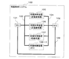
- FIG. 1 is a diagram showing a configuration of the protection control system 100.
- the protection control system 100 includes a MU (Merging Unit) 101, a process bus 103, and protection control devices 105 to 108.
- MU Management Unit
- the MU 101 detects electric quantities of CT (Current Transformer) and VT (Voltage Transformer) (not shown) installed in the electric power system, and outputs them to the process bus 103 as electric quantity information.
- the MU 101 receives trip information from the process bus 103, and outputs a trip command for opening a circuit breaker (not shown) when a trip condition is satisfied.
- the trip information includes 87 trip information, 44 / 51G trip information, B87G / B87S trip information, 27F trip information, 51DF / 64F trip information, and 27F / 64F trip. Indicates information. Tripping means that in a power system, a circuit breaker or a switch is opened for some reason and power transmission is stopped.
- the process bus 103 is connected to the MU 101 and the protection control devices 105 to 108, and realizes mutual information transmission between the MU 101 and the protection control devices 105 to 108.
- the protection control device 105 is configured by a computer including a CPU, a memory, and the like, and is connected to the process bus 103.
- the protection control device 105 determines a system fault in the protection target section based on the electrical quantity information received from the MU 101 via the process bus 103. If the protection control device 105 determines that a system fault has occurred in the protection target section, it outputs 87 trip information to the process bus 103.
- the protection control device 105 here determines a system fault in the protection target section for the purpose of protecting the transmission line, and the relay characteristic uses the current differential relay system (87).
- the protection control device 106 Since the protection control device 106 is the same as the protection control device 105, detailed description is omitted, but the distance relay method (44) and the ground fault overcurrent relay method (51G) are used as relay characteristics.
- the protection control device 106 determines that a system fault has occurred in the protection target section, it outputs 44 ⁇ 51G trip information to the process bus 103.
- the protection control device 107 Since the protection control device 107 is the same as the protection control device 105, detailed description is omitted, but the protection target is a bus, and the ratio differential relay system (B87G, B87S) is used as a relay characteristic. Use the method.
- the protection control device 107 determines that a system fault has occurred in the protection target section, the B87G / B87S trip information is output to the process bus 103.
- control device number is written in parentheses, and the following is also described in the same way.
- the protection control device 108 is configured by a computer including a CPU, a memory, and the like, and is connected to the process bus 103.
- the protection control device 108 determines whether or not to open a circuit breaker (not shown) based on the electrical quantity information received from the MU 101 via the process bus 103.
- the protection control device 108 serves as the FD of the protection control devices 105 to 107, and includes relay characteristics such as an AC undervoltage relay system (27F), a current change width relay system (51DF), and a ground fault overvoltage.
- a relay system (64F) is used. If the protection control device 108 determines that a system fault has occurred in the protection target section, it outputs 27F trip information, 51DF / 64F trip information, or 27F / 64F trip information to the process bus 103.
- the protection control device 108 operates as the FD of the protection control devices 105 to 107.
- the FD of the protection control device 105 is an AC undervoltage relay method (27F)
- the FD of the protection control device 106 is a current change width relay method (51DF) and a ground fault overvoltage relay method (64F).
- the FD of the control device 107 is an AC undervoltage relay system (27F) and a ground fault overvoltage relay system (64F).
- the 87 trip information, 44 / 51G trip information, and B87G / B87S trip information output from the protection control devices 105 to 107 are referred to as main trip information, and the 27F trip information and 51DF / 64F trip output from the protection control device 108.
- Information and 27F / 64F trip information are called FD trip information.
- the protection control devices 105 to 107 that output main trip information are called first protection control devices, and the protection control device 108 that outputs FD trip information is called a second protection control device.
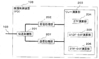
- FIG. 2 is a functional block diagram showing the configuration of the protection control device 108.
- the protection control device 108 includes a transmission processing unit 201, a reception processing unit 202, a relay calculation unit 203, and a transmission processing unit 207. Furthermore, the relay calculation unit 203 includes a 27F calculation unit 204, a 51DF / 64F calculation unit 205, and a 27F / 64F calculation unit 206.
- the three calculation units of the 27F calculation unit 204, the 51DF / 64F calculation unit 205, and the 27F / 64F calculation unit 206 are collectively referred to as each calculation unit.
- the transmission processing unit 201 is connected to the process bus 103, the reception processing unit 202, and the transmission processing unit 207.
- the transmission processing unit 201 acquires electrical quantity information from the MU 101 via the process bus 103 and outputs it to the reception processing unit 202.
- the transmission processing unit 201 acquires the FD trip information output from the transmission processing unit 207 and outputs the FD trip information to the process bus 103.
- the reception processing unit 202 is connected to the transmission processing unit 201 and the relay calculation unit 203.
- the reception processing unit 202 converts the electrical quantity information acquired from the transmission processing unit 201 and outputs the converted information to the relay calculation unit 203.
- the conversion here converts the electrical quantity information transmitted through the process bus 103 into a format that can be processed by the relay operation unit 203.
- the relay calculation unit 203 is realized mainly by a program operated by a CPU, and is stored in a storage medium (not shown) such as an HDD, an SSD (Solid State Drive), a RAM, or the like.
- the relay calculation unit 203 includes a 27F calculation unit 204, a 51DF / 64F calculation unit 205, and a 27F / 64F calculation unit 206.
- the 27F calculation unit 204 functions as the FD of the protection control device 105 in FIG. 1
- the 51DF / 64F calculation unit 205 functions as the FD of the protection control device 106 in FIG.
- the 64F calculation unit 206 functions as the FD of the protection control device 107.
- the 27F calculation unit 204 determines whether or not to output the 27F trip information to the transmission processing unit 207 based on the electrical quantity information acquired from the reception processing unit 202.
- the 51DF / 64F calculation unit 205 determines whether or not to output the 51DF / 64F trip information to the transmission processing unit 207 based on the electrical quantity information acquired from the reception processing unit 202.
- the 27F / 64F calculation unit 206 determines whether to output the 27F / 64F trip information to the transmission processing unit 207 based on the electrical quantity information acquired from the reception processing unit 202.
- the transmission processing unit 207 is connected to the relay calculation unit 203 and the transmission processing unit 201.
- the transmission processing unit 207 converts the FD trip information acquired from the relay calculation unit 203 and outputs the FD trip information to the transmission processing unit 201. In this conversion, the FD trip information acquired from the relay calculation unit 203 is converted into a format that can be transmitted by the process bus 103.
- the configuration of the protection control devices 105 to 107 shown in FIG. 1 is different from the configuration of the protection control device 108 described above in that the protection control device 108 includes a plurality of arithmetic units, whereas the protection control devices 105 to 107 are The point which is equipped with the single calculating part which detects the system fault of a protection object area.
- the protection control device 105 includes a calculation unit that performs a current differential relay calculation (87), and determines whether to output 87 trip information.
- the protection control device 106 includes a calculation unit that performs a distance relay calculation (44) and a ground fault overcurrent relay calculation (51G), and determines whether to output 44 ⁇ 51G trip information.
- the protection control device 107 includes a calculation unit that performs ratio differential relay calculation (B87G, B87S), and determines whether to output B87G / B87S trip information.
- the above trip information refers to main trip information (87 trip information, 44 / 51G trip information, B87G / B87S trip information) or FD trip information (27F trip information, 51DF / 64F trip information, 27F / 64F trip information). In the following, similar expressions are used.
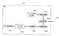
- FIG. 3 is a functional block diagram showing the configuration of the MU 101.
- the configuration of the MU 101 includes an input converter 301, an analog filter 302, an AD converter 303, a transmission processing unit 304, a transmission processing unit 305, a reception processing unit 306, and a trip command output unit 307.
- the input converter 301 is connected to the CT and VT and the analog filter 302 (not shown), acquires the electric quantity of the power system measured by the CT / VT, and outputs it to the analog filter 302.
- the analog filter 302 is connected to the input converter 301 and the AD converter 303, removes noise and harmonic components of the electric quantity acquired from the input converter 301, and outputs them to the AD converter 303.
- the AD converter 303 is connected to the analog filter 302 and the transmission processing unit 304, digitizes the electric quantity of the analog data acquired from the analog filter 302, and outputs it to the transmission processing unit 304 as electric quantity information.
- the transmission processing unit 304 is connected to the AD converter 303 and the transmission processing unit 305, converts the electric quantity information of the digital data acquired from the AD converter 303, and outputs it to the transmission processing unit 305. In this conversion, the electric quantity information is converted into a format that can be transmitted using the process bus 103.
- the transmission processing unit 305 is connected to the transmission processing unit 304, the reception processing unit 306, and the process bus 103, and outputs the electrical quantity information acquired from the transmission processing unit 304 to the process bus 103. Further, the transmission processing unit 305 acquires trip information from the process bus 103 and outputs the trip information to the reception processing unit 306.
- the reception processing unit 306 is connected to the transmission processing unit 305 and the trip command output unit 307, converts the trip information acquired from the transmission processing unit 305, and outputs the trip information to the trip command output unit 307.
- the trip command output unit 307 is configured by a trip circuit.
- the trip command output unit 307 is connected to the reception processing unit 306 and a circuit breaker (not shown), and determines whether or not to open the circuit breaker (not shown) based on the trip information acquired from the reception processing unit 306. To do.
- the trip command output unit 307 determines to open the circuit breaker, the trip command output unit 307 outputs a trip command to the circuit breaker.
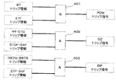
- FIG. 4 shows a control logic configuration of the trip command output unit 307.
- the control logic configuration of the trip command output unit 307 includes AND gates 401 to 403.
- the trip command output unit 307 determines to open the circuit breaker or the switch when the FD trip information corresponding to the accident detection relay of the acquired main trip information is acquired. That is, when trip command output unit 307 receives 87 trip information and 27F trip information, trip command output unit 307 outputs a PCM trip command.
- the PCM trip command is a trip signal from the current differential relay.
- trip command output unit 307 receives 44 ⁇ 51G trip information and 51DF ⁇ 64F trip information
- trip command output unit 307 outputs a DZ trip command.
- the DZ trip command is a trip signal from the distance relay.
- trip command output unit 307 receives B87G / B87S trip information and 27F / 64F trip information
- trip command output unit 307 outputs a BP trip command.
- the BP trip command is a trip signal from the bus protection relay.
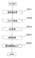
- FIG. 5 is a flowchart showing the operation of the MU 101, and includes the following steps.
- the input converter 301 obtains an electric quantity from CT / VT (not shown) (S501).
- the analog filter 302 removes noise and harmonic components from the amount of electricity acquired from the input converter 301 (S502).
- a step in which the AD converter 303 digitally converts the amount of electricity acquired from the analog filter 302 into amount of electricity information (S503).
- the transmission processing unit 304 converts the electrical quantity information acquired from the AD converter 303 into a transmittable format (S504).
- the transmission processing unit 305 outputs the electrical quantity information acquired from the transmission processing unit 304 to the process bus 103 (S505).
- FIG. 6 is a flowchart showing the operation of the protection control apparatus 108, and includes the following steps.
- the transmission processing unit 201 acquires electrical quantity information from the process bus 103 (S601).
- the reception processing unit 202 converts the electrical quantity information acquired from the transmission processing unit 201 into a format that can be relayed (S602).
- the 27F calculation unit 204, 51DF / 64F calculation unit 205, and 27F / 64F calculation unit 206 constituting the relay calculation unit 203 are protected based on the electrical quantity information acquired from the reception processing unit 202 and the respective relay characteristics.
- a step of determining whether or not a system fault has occurred in the section (S603). Here, when it is determined that no system fault has occurred (NO in S603), the flow ends.
- the relay calculation unit 203 transmits the transmission processing unit 207.
- the FD trip information is output to the transmission processing unit 207, and the transmission processing unit 207 converts the FD trip information acquired from the relay calculation unit 203 into a transmittable format (S604).
- the transmission processing unit 201 outputs the FD trip information acquired from the transmission processing unit 207 to the process bus 103 (S605).
- the operation of the protection control device 108 has been described here, the operation of the protection control devices 105 to 107 is performed by a single relay operation unit in the step of determining whether or not to output FD trip information (S603). The difference is that one type of main trip information is output according to the relay characteristics.
- FIG. 7 is a flowchart showing the operation of the MU 101, and includes the following steps.
- Step in which the transmission processing unit 305 acquires trip information from the process bus 103 (S701)
- the reception processing unit 306 acquires the trip information from the transmission processing unit 305 and converts the trip command output unit 307 into a format that can determine whether or not to output the trip command (S702).
- the trip command output unit 307 determines whether or not to open the circuit breaker based on the trip information acquired from the reception processing unit 306 and the control logic configuration (S703). When it is determined not to open the circuit breaker (NO in S703), the flow is terminated.
- Step (S703) If the step of determining whether or not to open the circuit breaker (S703) determines that the circuit breaker is to be opened (YES in S703), the trip command output unit 307 outputs a trip command to the circuit breaker (not shown). Step (S704).
- each of the protection control devices is provided with a main and an FD. Therefore, it is necessary to have relay hardware twice the number of protection control devices connected to the same process bus. In the protection control system adapted to the above, the amount of hardware increases, which increases the cost. However, according to the protection control system 100 of the present embodiment, the hardware amount can be reduced by providing the single protection control device 108 as the FD of the protection control devices 105 to 107 connected to the same process bus 103.
- the protection control devices 105 to 107 are responsible for transmission line protection (PCM, DZ) and bus protection as an example, but a protection control device for transformer protection may be used.
- PCM transmission line protection
- DZ protection control device for transformer protection
- the relay characteristics described in the present embodiment are merely examples, and a current balance protection control device or the like that monitors the current balance of each line based on Kirchhoff's law may be used.
- the protection control device for busbar protection does not assume the provision of main and FD relays.
- the protection control device that determines the divisional interruption of the busbars and the protection control device that determines the simultaneous interruption of the busbars, the protection control device that determines the simultaneous interruption of the busbars, the protection control that integrates the functions of the FD You may mount in an apparatus (this protection control apparatus 108).
- control logic configuration of the trip command output unit 307 of the MU 101 of the present embodiment is shown in FIG. 4, the control logic configuration shown in FIG. This control logic configuration includes an OR gate 801 and AND gates 802 to 804.
- the trip command output unit 307 receives any of 27F trip information, 51DF / 64F trip information, and 27F / 64F trip information and 87 trip information
- the trip command output unit 307 outputs a PCM trip command.
- the trip command output unit 307 receives any of 27F trip information, 51DF / 64F trip information, and 27F / 64F trip information and 44 ⁇ 51G trip information
- the trip command output unit 307 outputs a DZ trip command.
- trip command output unit 307 receives any of 27F trip information, 51DF / 64F trip information, and 27F / 64F trip information and B87G / B87S trip information
- trip command output unit 307 outputs a BP trip command.
- the contact hardware of the trip circuit provided in the trip command output unit 307 can be reduced as compared with the control logic configuration of FIG.
- the protection control devices 105 to 108 may be connected to the spare MU via the spare process bus.
- the protection control devices 105 to 108 switch to the spare MU.
- the power system can be operated more stably.
- the state of the spare MU described above can be a hot standby state, a warm standby state, or a cold standby state.
- the hot standby state indicates a state where the spare MU performs the same operation as when the MU 101 is normal. That is, similarly to the MU 101, the spare MU also detects the amount of electricity from the CT / VT installed in the power system, and outputs the amount of electricity information to the protection control devices 105 to 108. When there is no failure, the protection control devices 105 to 108 discard the electrical quantity information acquired from the backup MU. When a failure occurs, the protection control devices 105 to 108 determine whether to output trip information based on the electrical quantity information acquired from the standby MU.
- the warm standby state indicates a state in which the standby MU is activated, but an application for outputting electric quantity information is not activated.
- the backup MU does not output the electric quantity information, and the protection control devices 105 to 108 determine whether to output trip information based on the electric quantity information acquired from the MU 101.
- the spare MU activates an application for outputting the electric quantity information, and outputs the electric quantity information to the protection control devices 105 to 108 via the spare process bus.
- the protection control devices 105 to 108 receive the information from the spare MU. It is determined whether to output trip information based on the acquired electric quantity information.
- the cold standby state indicates a state where the spare MU is not activated. At the normal time without a failure, the spare MU is not activated. When a failure occurs, the spare MU outputs the electrical quantity information to the protection control devices 105 to 108 via the spare process bus after activation, and the protection control devices 105 to 108 trip based on the electrical quantity information acquired from the spare MU. Determine whether to output information.
- the MU 102 has the same function and configuration as the MU 101, and the process bus 104 has the same function and configuration as the process bus 103.
- the protection control devices 105 to 107 and 108-2 are connected to the process buses 103 and 104.
- the protection control device 108-2 is configured by a computer including a CPU, a memory, and the like.
- the protection control device 108-2 is different from the protection control device 108 of the first embodiment in that it is connected to the process bus 104 in addition to the process bus 103, and acquires electrical quantity information from the MU 102 via the process bus 104. Is a point. Furthermore, based on this electrical quantity information, the protection control device 108-2 determines whether or not to open a circuit breaker (not shown). When the protection control device 108-2 determines to open the circuit breaker, the protection control device 108-2 outputs FD trip information to the process bus 103.
- FIG. 10 is a functional block diagram showing the configuration of the protection control device 108-2.
- the protection control device 108-2 is different from the protection control device 108 of the first embodiment in that transmission processing units 208 and 209 are provided instead of the transmission processing unit 201.
- the transmission processing unit 208 is connected to the process bus 103 and the reception processing unit 202, acquires the electrical quantity information output from the MU 101 via the process bus 103, and outputs it to the reception processing unit 202.
- the transmission processing unit 209 is connected to the transmission processing unit 207 and the process bus 104, and outputs the FD trip information output from the transmission processing unit 207 to the MU 102 via the process bus 104.
- the protection control system 100 of this embodiment in addition to the effects of the first embodiment, by providing redundant MUs 101 and 102 and process buses 103 and 104, if any device has a defect, It is possible to substitute normal equipment. Therefore, a highly reliable power system can be operated.
- the protection control system 100 of the third embodiment will be described with reference to FIG. 11, but the same reference numerals are given to the same configurations as those of the first embodiment, and the description thereof will be omitted.
- the configuration of the present embodiment is different from that of the first embodiment in that the protection control system 100 further includes an MU 102 and a process bus 104, and the protection control device 108 is replaced with a protection control device 108-3. Further, the MU 101 and the MU 102 are connected by a cable 109.
- the MU 102 has the same function and configuration as the MU 101, and the process bus 104 has the same function and configuration as the process bus 103.
- the protection control devices 105 to 108-3 are connected to the process buses 103 and 104.
- the protection control device 108-3 has substantially the same configuration as that of the protection control device 108 of the first embodiment, but acquires the electrical quantity information via the process bus 104 and the FD trip information via the process bus 104. The difference is that it is output to the MU 102.
- the cable 109 is realized by a metal cable or the like and is connected to the MU 101 and the MU 102. Therefore, the trip information obtained by the MU 102 is transferred to the MU 101 by connecting the trip circuit constituting the trip command output unit 307 of the MU 101 and the trip circuit constituting the trip command output unit of the MU 102.
- the MU 101 acquires the main trip information (87 trip information, 44 / 51G trip information, and B87G / B87S trip information) acquired from the process bus 103 and the FD trip information (27F trip information, 27F trip information, Based on the 51DF / 64F trip information and 27F / 64F trip information), it is determined whether to output a trip command from the control logic configuration shown in FIG.
- the protection control system 100 of this embodiment in addition to the effects of the first embodiment, by providing redundant MUs 101 and 102 and process buses 103 and 104, if any device has a defect, It is possible to substitute normal equipment. Therefore, a highly reliable power system can be operated.
- the embodiment of the present invention it is possible to provide a protection control system, a protection control device, and a merging unit that reduce the amount of hardware in the protection control system to which the process bus is applied.
- Protection control system 101 Protection control system 101, 102: Merging unit (MU) 103, 104 ... Process buses 105 to 108, 105 to 108-2, 105 to 108-3 ... Protection control device 109 ... Cables 201, 208, 209 ... Transmission processing part 202 ... Reception processing part 203 ... Relay operation part 204 ... 27F Calculation unit 205 ... 51DF / 64F calculation unit 206 ... 27F / 64F calculation unit 207 ... Transmission processing unit 301 ... Input converter 302 ... Analog filter 303 ... AD converter 304 ... Transmission processing unit 305 ... Transmission processing unit 306 ... Reception processing unit 307 ... Trip command output section
Landscapes
- Engineering & Computer Science (AREA)
- Power Engineering (AREA)
- Emergency Protection Circuit Devices (AREA)
- Remote Monitoring And Control Of Power-Distribution Networks (AREA)
- Supply And Distribution Of Alternating Current (AREA)
Abstract
Description
第1の実施形態の保護制御システムの構成について図1を用いて説明する。図1は、保護制御システム100の構成を示す図である。
次に、保護制御システム100を構成している、MU101および保護制御装置105~108の動作について図5乃至図7を用いて説明する。
・受信処理部306が、伝送処理部305からトリップ情報を取得し、トリップ指令出力部307がトリップ指令を出力するか否かを判断可能な形式に変換するステップ(S702)
・トリップ指令出力部307が、受信処理部306から取得したトリップ情報と制御ロジック構成に基づいて、遮断器を開放するか否かを判断するステップ(S703)。遮断器を開放しないと判断した場合(S703のNO)、フローを終了する。
従来の保護制御システムでは、保護制御装置夫々について、メインとFDを備えていたため、同一のプロセスバスに接続する保護制御装置の台数の2倍のリレーハードウェアが必要であるため、複雑な電力系統に適応される保護制御システムにおいては、ハードウェア量が増大し、コストを増加させる原因になっていた。しかし、本実施形態の保護制御システム100によれば、同一のプロセスバス103に接続する保護制御装置105~107のFDとして、単数の保護制御装置108を備えることによって、ハードウェア量を削減できる。
第2の実施形態の保護制御システム100について図9を用いて説明するが、本実施形態が第1の実施形態と同一の構成には同一の符号を付し、説明は省略する。本実施形態の構成が第1の実施形態と異なる点は、MU102およびプロセスバス104をさらに備え、保護制御装置108が保護制御装置108-2に代替した点が異なる。
第3の実施形態の保護制御システム100について図11を用いて説明するが、本実施形態が第1の実施形態と同一の構成には同一の符号を付し、説明は省略する。本実施形態の構成が第1の実施形態と異なる点は、保護制御システム100はMU102およびプロセスバス104をさらに備え、保護制御装置108が保護制御装置108-3に代替した点が異なる。さらに、MU101とMU102がケーブル109により接続している。
101、102…マージングユニット(MU)
103、104…プロセスバス
105~108、105~108-2、105~108-3…保護制御装置
109…ケーブル
201、208、209…伝送処理部
202…受信処理部
203…リレー演算部
204…27F演算部
205…51DF・64F演算部
206…27F・64F演算部
207…送信処理部
301…入力変換器
302…アナログフィルタ
303…AD変換器
304…送信処理部
305…伝送処理部
306…受信処理部
307…トリップ指令出力部
Claims (8)
- 電力系統に設置された変成器から電気量を取得し、取得した前記電気量をディジタル変換し、第一の電気量情報として第一のネットワークに出力する第一のマージングユニットと、
前記第一のマージングユニットから、前記第一のネットワークを介して前記第一の電気量情報を取得し、予め決められたリレー特性に基づいて、前記電力系統の保護対象区間に系統事故が発生しているか否かを判断し、系統事故が発生していると判断した場合、メイントリップ情報を前記第一のネットワークに出力する複数の第一の保護制御装置と、
前記第一のマージングユニットから、前記第一のネットワークを介して前記第一の電気量情報を取得し、前記第一の保護制御装置夫々の事故検出リレーとして予め決められた複数のリレー特性に基づいて、前記電力系統の保護対象区間に系統事故が発生しているか否かを判断し、系統事故が発生していると判断した場合、FDトリップ情報を前記第一のネットワークに出力する第二の保護制御装置と、を備え、
前記第一のマージングユニットは、前記メイントリップ情報および前記FDトリップ情報に基づいて、前記電力系統に設置された遮断器または開閉器の開閉を判断する保護制御システム。 - 電力系統に設置された変成器から電気量を取得し、取得した電気量をディジタル変換し、第一の電気量情報として第一のネットワークに出力する第一のマージングユニットと、
電力系統に設置された変成器から電気量を取得し、取得した電気量をディジタル変換し、第二の電気量情報として第二のネットワークに出力する第二のマージングユニットと、
前記第一のマージングユニットから、前記第一のネットワークを介して前記第一の電気量情報を取得し、予め決められたリレー特性に基づいて、前記電力系統の保護対象区間に系統事故が発生しているか否かを判断し、系統事故が発生していると判断した場合、メイントリップ情報を前記第一のネットワークに出力する第一の保護制御装置と、
前記第二のマージングユニットから、前記第二のネットワークを介して前記第二の電気量情報を取得し、前記第一の保護制御装置夫々の事故検出リレーとして予め決められた複数のリレー特性に基づいて、前記電力系統の保護対象区間に系統事故が発生しているか否かを判断し、系統事故が発生していると判断した場合、FDトリップ情報を前記第一のネットワークに出力する第二の保護制御装置と、を備え、
前記第一のマージングユニットは、前記メイントリップ情報および前記FDトリップ情報に基づいて、電力系統に設置された遮断器または開閉器の開閉を判断する保護制御システム。 - 電力系統に設置された変成器から電気量を取得し、取得した電気量をディジタル変換し、第一の電気量情報として第一のネットワークに出力する第一のマージングユニットと、
電力系統に設置された変成器から電気量を取得し、取得した電気量をディジタル変換し、前記第一の電気量情報と異なる第二の電気量情報として第二のネットワークに出力する第二のマージングユニットと、
前記第一のマージングユニットから、前記第一のネットワークを介して前記第一の電気量情報を取得し、予め決められたリレー特性に基づいて、前記電力系統の保護対象区間の系統事故が発生しているか否かを判断し、系統事故が発生していると判断した場合、メイントリップ情報を前記第一のネットワークに出力する複数の第一の保護制御装置と、
前記第二のマージングユニットから、前記第二のネットワークを介して前記電気量情報を取得し、前記第一の保護制御装置夫々の事故検出リレーとして予め決められた複数のリレー特性に基づいて、前記電力系統の保護対象区間の系統事故が発生しているか否かを判断し、系統事故が発生していると判断した場合、FDトリップ情報を前記第二のネットワークに出力する第二の保護制御装置と、
前記第一のマージングユニットと前記第二のマージングユニットとを接続するケーブルと、 を備え、
前記第一のマージングユニットは、前記第一の保護制御装置から出力された前記メイントリップ情報と、前記第二の保護制御装置から前記ケーブルを介して出力された前記FDトリップ情報とに基づいて、電力系統に設置された遮断器または開閉器の開閉を判断する保護制御システム。 - 前記第一のマージングユニットは、前記メイントリップ情報および前記FDトリップ情報を取得し、前記FDトリップ情報が前記メイントリップ情報の事故検出リレーに対応するリレー特性に基づいて出力された場合に、前記遮断器または前記開閉器を開放すると判断する
請求項1乃至3の何れか1項に記載の保護制御システム。 - 電力系統に設置された変成器から電気量を取得し、取得した電気量をディジタル変換し、電気量情報として出力するマージングユニットから、ネットワークを介して電気量情報を受信する伝送処理部と、
前記伝送処理部から取得した前記電気量情報と、固有のリレー特性を持つ複数の第一の保護制御装置夫々の事故検出リレーとして予め決められた複数のリレー特性と、に基づいて、保護対象区間の系統事故が発生しているか否かを判断し、系統事故が発生していると判断した場合、FDトリップ情報を前記伝送処理部に出力するリレー演算部と、を備え、
前記伝送処理部は、前記リレー演算部から取得した前記FDトリップ情報を前記ネットワークに出力する保護制御装置。 - 電力系統に設置された変成器から電気量を取得し、取得した電気量をディジタル変換し、電気量情報として出力するマージングユニットから、第一のネットワークを介して電気量情報を受信する第一の伝送処理部と、
前記電気量情報と、予め決められたリレー特性と、に基づいて、前記電力系統の保護対象区間の系統事故が発生しているか否かを判断し、系統事故が発生していると判断した場合、FDトリップ情報を出力するリレー演算部と、
前記リレー演算部から取得した前記FDトリップ情報を第二のネットワークに出力する第二の伝送処理部と、を備え、
前記リレー演算部は、前記第一のネットワークまたは前記第二のネットワークに接続する複数の保護制御装置夫々の事故検出リレーとして予め決められた複数のリレー特性に基づいて判断する保護制御装置。 - 電力系統に設置された変成器により検出された電気量を取得する入力変換器と、
前記入力変換器が取得した前記電気量を、電気量情報としてディジタル変換するAD変換器と、
前記AD変換器から前記電気量情報を取得し、ネットワークに出力する伝送処理部と、
電力系統に設置される遮断器または開閉器を開放するか否かを判断するトリップ指令出力部と、を備え、
前記伝送処理部は、予め決められたリレー特性を持つ複数の第一の保護制御装置から出力されたメイントリップ情報と、前記第一の保護制御装置夫々の事故検出リレーとして予め決められた複数のリレー特性を持つ第二の保護制御装置から出力されたFDトリップ情報と、を取得し、
前記トリップ指令出力部は、前記メイントリップ情報および前記FDトリップ情報に基づいて、前記遮断器または前記開閉器の開閉を判断するマージングユニット。 - 前記トリップ指令出力部は、前記伝送処理部が前記メイントリップ情報及び前記FDトリップ情報を取得し、前記FDトリップ情報が前記メイントリップ情報の事故検出リレーに対応するリレー特性に基づいて出力された場合に、前記遮断器または前記開閉器を開放すると判断する
請求項7に記載のマージングユニット。
Priority Applications (5)
| Application Number | Priority Date | Filing Date | Title |
|---|---|---|---|
| CN201280055255.7A CN103931070B (zh) | 2011-11-11 | 2012-09-11 | 保护控制系统、保护控制装置以及合并单元 |
| EP12848502.6A EP2779342B1 (en) | 2011-11-11 | 2012-09-11 | Protection control system, protection control devices, and merging unit |
| BR112014011338A BR112014011338A2 (pt) | 2011-11-11 | 2012-09-11 | sistema de proteção e controle, dispositivo de proteção e controle, e unidade de associação |
| IN3505DEN2014 IN2014DN03505A (ja) | 2011-11-11 | 2012-09-11 | |
| US14/260,996 US9450400B2 (en) | 2011-11-11 | 2014-04-24 | Protection and control system, protection and control device, and merging unit |
Applications Claiming Priority (2)
| Application Number | Priority Date | Filing Date | Title |
|---|---|---|---|
| JP2011-247945 | 2011-11-11 | ||
| JP2011247945A JP5926539B2 (ja) | 2011-11-11 | 2011-11-11 | 保護制御システム、保護制御装置、およびマージングユニット |
Related Child Applications (1)
| Application Number | Title | Priority Date | Filing Date |
|---|---|---|---|
| US14/260,996 Continuation US9450400B2 (en) | 2011-11-11 | 2014-04-24 | Protection and control system, protection and control device, and merging unit |
Publications (1)
| Publication Number | Publication Date |
|---|---|
| WO2013069181A1 true WO2013069181A1 (ja) | 2013-05-16 |
Family
ID=48288958
Family Applications (1)
| Application Number | Title | Priority Date | Filing Date |
|---|---|---|---|
| PCT/JP2012/005731 Ceased WO2013069181A1 (ja) | 2011-11-11 | 2012-09-11 | 保護制御システム、保護制御装置、およびマージングユニット |
Country Status (7)
| Country | Link |
|---|---|
| US (1) | US9450400B2 (ja) |
| EP (1) | EP2779342B1 (ja) |
| JP (1) | JP5926539B2 (ja) |
| CN (1) | CN103931070B (ja) |
| BR (1) | BR112014011338A2 (ja) |
| IN (1) | IN2014DN03505A (ja) |
| WO (1) | WO2013069181A1 (ja) |
Families Citing this family (5)
| Publication number | Priority date | Publication date | Assignee | Title |
|---|---|---|---|---|
| JP2015023633A (ja) * | 2013-07-17 | 2015-02-02 | 株式会社東芝 | 保護制御システムおよびインタフェース装置 |
| US10644498B2 (en) * | 2017-02-22 | 2020-05-05 | Aab Schweiz Ag | Power distribution systems and methods of performing zone selective interlocking in power distribution systems with a communication network |
| WO2020209523A1 (ko) * | 2019-04-10 | 2020-10-15 | 엘에스일렉트릭(주) | 보호계전기 검사 장치 |
| EP4073934B1 (en) * | 2019-12-09 | 2025-05-14 | Lattice Semiconductor Corporation | Input/output bus protection systems and methods for programmable logic devices |
| JP2025041465A (ja) * | 2023-09-13 | 2025-03-26 | 株式会社日立製作所 | 保護制御システムおよび保護制御方法 |
Citations (5)
| Publication number | Priority date | Publication date | Assignee | Title |
|---|---|---|---|---|
| JP2004072905A (ja) * | 2002-08-06 | 2004-03-04 | Toshiba Corp | ディジタル形保護制御装置 |
| JP3907998B2 (ja) | 2001-02-09 | 2007-04-18 | 株式会社東芝 | 変電機器保護制御システム |
| JP2007288921A (ja) * | 2006-04-17 | 2007-11-01 | Toshiba Corp | 開閉装置制御・監視システム |
| JP2010068594A (ja) * | 2008-09-09 | 2010-03-25 | Mitsubishi Electric Corp | 保護制御システム |
| JP2011223647A (ja) * | 2010-04-05 | 2011-11-04 | Hitachi Ltd | 分散形ディジタル保護リレー |
Family Cites Families (5)
| Publication number | Priority date | Publication date | Assignee | Title |
|---|---|---|---|---|
| WO2008040263A1 (de) * | 2006-10-04 | 2008-04-10 | Siemens Aktiengesellschaft | Redundantes schutzsystem und verfahren zum redundanten überwachen von schutzobjekten in einem elektrischen energieversorgungsnetz |
| JP2008125251A (ja) * | 2006-11-13 | 2008-05-29 | Mitsubishi Electric Corp | 電気所におけるリレー方式およびpcm電流差動リレー方式 |
| EP2159893A1 (en) * | 2008-08-29 | 2010-03-03 | ABB Research LTD | Substation automation with redundant protection |
| CN102484394A (zh) * | 2009-04-13 | 2012-05-30 | Abb研究有限公司 | 智能过程接口和变电站自动化系统 |
| CN102986106B (zh) * | 2010-03-31 | 2016-04-27 | Abb研究有限公司 | 用于在变电站系统中的装置之间转移控制的方法及其装置 |
-
2011
- 2011-11-11 JP JP2011247945A patent/JP5926539B2/ja active Active
-
2012
- 2012-09-11 EP EP12848502.6A patent/EP2779342B1/en active Active
- 2012-09-11 BR BR112014011338A patent/BR112014011338A2/pt not_active Application Discontinuation
- 2012-09-11 CN CN201280055255.7A patent/CN103931070B/zh active Active
- 2012-09-11 WO PCT/JP2012/005731 patent/WO2013069181A1/ja not_active Ceased
- 2012-09-11 IN IN3505DEN2014 patent/IN2014DN03505A/en unknown
-
2014
- 2014-04-24 US US14/260,996 patent/US9450400B2/en active Active
Patent Citations (5)
| Publication number | Priority date | Publication date | Assignee | Title |
|---|---|---|---|---|
| JP3907998B2 (ja) | 2001-02-09 | 2007-04-18 | 株式会社東芝 | 変電機器保護制御システム |
| JP2004072905A (ja) * | 2002-08-06 | 2004-03-04 | Toshiba Corp | ディジタル形保護制御装置 |
| JP2007288921A (ja) * | 2006-04-17 | 2007-11-01 | Toshiba Corp | 開閉装置制御・監視システム |
| JP2010068594A (ja) * | 2008-09-09 | 2010-03-25 | Mitsubishi Electric Corp | 保護制御システム |
| JP2011223647A (ja) * | 2010-04-05 | 2011-11-04 | Hitachi Ltd | 分散形ディジタル保護リレー |
Non-Patent Citations (1)
| Title |
|---|
| See also references of EP2779342A4 |
Also Published As
| Publication number | Publication date |
|---|---|
| BR112014011338A2 (pt) | 2017-05-02 |
| EP2779342A4 (en) | 2015-09-23 |
| CN103931070A (zh) | 2014-07-16 |
| EP2779342A1 (en) | 2014-09-17 |
| JP5926539B2 (ja) | 2016-05-25 |
| CN103931070B (zh) | 2016-11-16 |
| US9450400B2 (en) | 2016-09-20 |
| US20140233143A1 (en) | 2014-08-21 |
| JP2013106419A (ja) | 2013-05-30 |
| IN2014DN03505A (ja) | 2015-05-15 |
| EP2779342B1 (en) | 2017-08-09 |
Similar Documents
| Publication | Publication Date | Title |
|---|---|---|
| JP5926540B2 (ja) | 保護制御システムおよびマージングユニット | |
| US8725305B2 (en) | Power distribution network fault management | |
| US9941739B2 (en) | Process bus associated protective control system, merging unit, and calculation device | |
| JP5926539B2 (ja) | 保護制御システム、保護制御装置、およびマージングユニット | |
| JP4731403B2 (ja) | 総合後備保護機能付き母線保護継電装置 | |
| KR102782446B1 (ko) | 변전소의 모선 보호 장치 및 방법 | |
| JP5426412B2 (ja) | 保護継電器 | |
| JP2015070769A (ja) | 保護制御システムおよびマージングユニット | |
| WO2012136241A1 (en) | Fault handling during circuit breaker maintenance in a double-breaker busbar switchyard | |
| JP5752845B2 (ja) | 統合ユニット及び保護リレーシステム | |
| EP3460935B1 (en) | Method and system for feeder protection in electrical power network | |
| KR102127471B1 (ko) | 변전소 종합 ai 후비보호시스템 | |
| JP6645759B2 (ja) | 電流差動リレーシステム | |
| JP4540621B2 (ja) | 電気所構内保護機能付き回線選択継電装置および電気所構内保護機能付き回線選択継電システム | |
| JP2017079543A (ja) | 母線保護継電装置 | |
| JPS6120209B2 (ja) | ||
| NZ601983B (en) | Power distribution network fault management | |
| JP2015019518A (ja) | 母線連絡継電装置 |
Legal Events
| Date | Code | Title | Description |
|---|---|---|---|
| 121 | Ep: the epo has been informed by wipo that ep was designated in this application |
Ref document number: 12848502 Country of ref document: EP Kind code of ref document: A1 |
|
| REEP | Request for entry into the european phase |
Ref document number: 2012848502 Country of ref document: EP |
|
| WWE | Wipo information: entry into national phase |
Ref document number: 2012848502 Country of ref document: EP |
|
| NENP | Non-entry into the national phase |
Ref country code: DE |
|
| REG | Reference to national code |
Ref country code: BR Ref legal event code: B01A Ref document number: 112014011338 Country of ref document: BR |
|
| ENP | Entry into the national phase |
Ref document number: 112014011338 Country of ref document: BR Kind code of ref document: A2 Effective date: 20140509 |