WO2013069243A1 - 固体電解質 - Google Patents
固体電解質 Download PDFInfo
- Publication number
- WO2013069243A1 WO2013069243A1 PCT/JP2012/007053 JP2012007053W WO2013069243A1 WO 2013069243 A1 WO2013069243 A1 WO 2013069243A1 JP 2012007053 W JP2012007053 W JP 2012007053W WO 2013069243 A1 WO2013069243 A1 WO 2013069243A1
- Authority
- WO
- WIPO (PCT)
- Prior art keywords
- solid electrolyte
- sulfide
- peak
- electrolyte according
- ppm
- Prior art date
- Legal status (The legal status is an assumption and is not a legal conclusion. Google has not performed a legal analysis and makes no representation as to the accuracy of the status listed.)
- Ceased
Links
Images




Classifications
-
- H—ELECTRICITY
- H01—ELECTRIC ELEMENTS
- H01M—PROCESSES OR MEANS, e.g. BATTERIES, FOR THE DIRECT CONVERSION OF CHEMICAL ENERGY INTO ELECTRICAL ENERGY
- H01M10/00—Secondary cells; Manufacture thereof
- H01M10/05—Accumulators with non-aqueous electrolyte
- H01M10/056—Accumulators with non-aqueous electrolyte characterised by the materials used as electrolytes, e.g. mixed inorganic/organic electrolytes
- H01M10/0561—Accumulators with non-aqueous electrolyte characterised by the materials used as electrolytes, e.g. mixed inorganic/organic electrolytes the electrolyte being constituted of inorganic materials only
- H01M10/0562—Solid materials
-
- C—CHEMISTRY; METALLURGY
- C03—GLASS; MINERAL OR SLAG WOOL
- C03C—CHEMICAL COMPOSITION OF GLASSES, GLAZES OR VITREOUS ENAMELS; SURFACE TREATMENT OF GLASS; SURFACE TREATMENT OF FIBRES OR FILAMENTS MADE FROM GLASS, MINERALS OR SLAGS; JOINING GLASS TO GLASS OR OTHER MATERIALS
- C03C10/00—Devitrified glass ceramics, i.e. glass ceramics having a crystalline phase dispersed in a glassy phase and constituting at least 50% by weight of the total composition
- C03C10/16—Halogen containing crystalline phase
-
- H—ELECTRICITY
- H01—ELECTRIC ELEMENTS
- H01B—CABLES; CONDUCTORS; INSULATORS; SELECTION OF MATERIALS FOR THEIR CONDUCTIVE, INSULATING OR DIELECTRIC PROPERTIES
- H01B1/00—Conductors or conductive bodies characterised by the conductive materials; Selection of materials as conductors
- H01B1/06—Conductors or conductive bodies characterised by the conductive materials; Selection of materials as conductors mainly consisting of other non-metallic substances
- H01B1/12—Conductors or conductive bodies characterised by the conductive materials; Selection of materials as conductors mainly consisting of other non-metallic substances organic substances
- H01B1/122—Ionic conductors
-
- H—ELECTRICITY
- H01—ELECTRIC ELEMENTS
- H01M—PROCESSES OR MEANS, e.g. BATTERIES, FOR THE DIRECT CONVERSION OF CHEMICAL ENERGY INTO ELECTRICAL ENERGY
- H01M10/00—Secondary cells; Manufacture thereof
- H01M10/05—Accumulators with non-aqueous electrolyte
- H01M10/052—Li-accumulators
-
- H—ELECTRICITY
- H01—ELECTRIC ELEMENTS
- H01M—PROCESSES OR MEANS, e.g. BATTERIES, FOR THE DIRECT CONVERSION OF CHEMICAL ENERGY INTO ELECTRICAL ENERGY
- H01M10/00—Secondary cells; Manufacture thereof
- H01M10/05—Accumulators with non-aqueous electrolyte
- H01M10/052—Li-accumulators
- H01M10/0525—Rocking-chair batteries, i.e. batteries with lithium insertion or intercalation in both electrodes; Lithium-ion batteries
-
- H—ELECTRICITY
- H01—ELECTRIC ELEMENTS
- H01M—PROCESSES OR MEANS, e.g. BATTERIES, FOR THE DIRECT CONVERSION OF CHEMICAL ENERGY INTO ELECTRICAL ENERGY
- H01M10/00—Secondary cells; Manufacture thereof
- H01M10/05—Accumulators with non-aqueous electrolyte
- H01M10/054—Accumulators with insertion or intercalation of metals other than lithium, e.g. with magnesium or aluminium
-
- C—CHEMISTRY; METALLURGY
- C03—GLASS; MINERAL OR SLAG WOOL
- C03C—CHEMICAL COMPOSITION OF GLASSES, GLAZES OR VITREOUS ENAMELS; SURFACE TREATMENT OF GLASS; SURFACE TREATMENT OF FIBRES OR FILAMENTS MADE FROM GLASS, MINERALS OR SLAGS; JOINING GLASS TO GLASS OR OTHER MATERIALS
- C03C2205/00—Compositions applicable for the manufacture of vitreous enamels or glazes
-
- H—ELECTRICITY
- H01—ELECTRIC ELEMENTS
- H01M—PROCESSES OR MEANS, e.g. BATTERIES, FOR THE DIRECT CONVERSION OF CHEMICAL ENERGY INTO ELECTRICAL ENERGY
- H01M2300/00—Electrolytes
- H01M2300/0017—Non-aqueous electrolytes
- H01M2300/0065—Solid electrolytes
- H01M2300/0068—Solid electrolytes inorganic
-
- H—ELECTRICITY
- H01—ELECTRIC ELEMENTS
- H01M—PROCESSES OR MEANS, e.g. BATTERIES, FOR THE DIRECT CONVERSION OF CHEMICAL ENERGY INTO ELECTRICAL ENERGY
- H01M2300/00—Electrolytes
- H01M2300/0017—Non-aqueous electrolytes
- H01M2300/0065—Solid electrolytes
- H01M2300/0068—Solid electrolytes inorganic
- H01M2300/008—Halides
-
- Y—GENERAL TAGGING OF NEW TECHNOLOGICAL DEVELOPMENTS; GENERAL TAGGING OF CROSS-SECTIONAL TECHNOLOGIES SPANNING OVER SEVERAL SECTIONS OF THE IPC; TECHNICAL SUBJECTS COVERED BY FORMER USPC CROSS-REFERENCE ART COLLECTIONS [XRACs] AND DIGESTS
- Y02—TECHNOLOGIES OR APPLICATIONS FOR MITIGATION OR ADAPTATION AGAINST CLIMATE CHANGE
- Y02E—REDUCTION OF GREENHOUSE GAS [GHG] EMISSIONS, RELATED TO ENERGY GENERATION, TRANSMISSION OR DISTRIBUTION
- Y02E60/00—Enabling technologies; Technologies with a potential or indirect contribution to GHG emissions mitigation
- Y02E60/10—Energy storage using batteries
Definitions
- the present invention relates to a solid electrolyte.
- Patent Document 1 Li 2 S and P 2 S 5 are mixed at a specific molar ratio (68:32 to 73:27), subjected to mechanical milling treatment, and subjected to heat treatment, thereby achieving high ion conduction. It has been reported that glass ceramic electrolyte particles having a degree ( ⁇ 2 ⁇ 10 ⁇ 3 S / cm) can be obtained. However, this material is easily hydrolyzed (contacts with water and generates hydrogen sulfide) and has limited use in high dew point environments. A technique for suppressing the hydrolyzability is proposed in Patent Document 2. However, in this technique, there is a problem that ion conductivity is greatly lowered instead of reducing the hydrolyzability.
- An object of the present invention is to provide a solid electrolyte that is hardly hydrolyzed and has high ionic conductivity.
- 2. The solid electrolyte according to 1, wherein the alkali metal element is lithium.
- 3. The solid electrolyte according to 1 or 2, having a peak in a peak region of 75.0 ppm or more and 80.0 ppm or less in a 1 P-NMR spectrum. 4).
- 4. The solid electrolyte according to any one of 1 to 3, having a peak in a peak region of 86.0 ppm or more and 92.0 ppm or less in a 31 P-NMR spectrum. 5.
- the 31 P-NMR spectrum has a first peak in a first peak region that is 75.0 ppm or more and 80.0 ppm or less,
- the intensity ratio of peaks in areas other than the first peak area and the second peak area that is 86.0 ppm or more and 92.0 ppm or less is 1 to 4 that is 0.5 or less with respect to the first peak.
- the solid electrolyte in any one. 6). 6.
- the solid electrolyte according to the peak intensity ratio (I 2 / I 1) is 1 to 10 6 of the second peak in the second peak region (I 2). 8).
- L a M b P c S d X e ... (A ')
- L represents an alkali metal
- M represents B, Al, Si, Ge, As, Se, Sn, Sb, Te, Pb or Bi, or a combination thereof
- X represents I, Cl, Br or F or a combination thereof
- d is 4. 15.
- w represents (An integer of 1 to 2 is indicated, and x is an integer of 1 to 10.) 19. 19. 19.
- the solid electrolyte according to 21, wherein the two crystallization peaks are in the range of 150 ° C. or higher and 360 ° C. or lower. 23. 23.
- the solid electrolyte according to 21 or 22, wherein the width between the two crystallization peaks is 20 to 100 ° C. 24. 24.
- An electrolyte layer comprising at least one of the solid electrolyte according to any one of 1 to 4 and 10 to 25 and the electrolyte-containing material according to 38.
- An electrolyte layer produced using at least one of the solid electrolyte according to any one of 1 to 4 and 10 to 25 and an electrolyte-containing material of 38.
- a battery in which at least one of the positive electrode layer, the electrolyte layer, and the negative electrode layer includes at least one of the solid electrolyte according to any one of 1 to 4 and 10 to 25 and the electrolyte-containing material of 38. 42.
- An electrolyte layer comprising at least one of the solid electrolyte according to any of 26 to 37 and the electrolyte-containing material according to 48 or 49.
- An electrolyte layer produced using at least one of the solid electrolyte according to any one of the above 26 to 37 and the electrolyte containing 48 or 49.
- 53. A battery in which at least one of the positive electrode layer, the electrolyte layer, and the negative electrode layer is produced using at least one of the solid electrolyte according to any one of 26 to 37 and the electrolyte content of 48 or 49.
- a solid electrolyte that is difficult to hydrolyze and has high ionic conductivity can be provided.
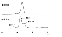
- FIG. 3 is a 31 P-NMR spectrum of the solid electrolyte obtained in Example 1 and the solid electrolyte obtained in Example 5.
- FIG. 3 is a 31 P-NMR spectrum of the solid electrolyte (sulfide glass) obtained in Example 10 (1) and the solid electrolyte (sulfide glass ceramic) obtained in (2).
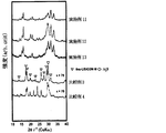
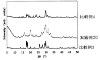
- FIG. 6 is a graph showing the results of powder X-ray diffraction of the solid electrolytes of Examples 11-13 and Comparative Examples 3 and 4.
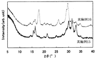
- FIG. 14 is a graph showing the result of powder X-ray diffraction of the solid electrolyte of Examples 16-19. It is a figure which shows the result of the powder X-ray diffraction of the solid electrolyte of Example 20 and Comparative Examples 3 and 4.
- the 1st solid electrolyte of this invention contains an alkali metal element, phosphorus, sulfur, and a halogen as a structural component.
- the first solid electrolyte of the present invention has a peak (hereinafter referred to as a first peak) in a peak region (hereinafter referred to as a first peak region) of 75.0 ppm to 80.0 ppm in a 31 P-NMR spectrum. ).
- the solid electrolyte specified by this peak condition is difficult to hydrolyze and has high ionic conductivity.
- the first peak may be a shoulder peak.
- a shoulder peak is a small peak that appears as a part of a large peak when two or more peaks of different sizes overlap. If there is no clear maximum point and the position of the peak top is unknown, the peak position of the shoulder peak is the point where the absolute value of the differential value in the peak region of 75.0 ppm to 80.0 ppm is the smallest.
- the first solid electrolyte of the present invention has a peak (hereinafter referred to as a second peak) in a peak region (hereinafter referred to as a second peak region) that is 86.0 ppm or more and 92.0 ppm or less. More preferred.
- the solid electrolyte specified by the peak condition is difficult to hydrolyze and has high ionic conductivity.
- the second peak may be a shoulder peak, and if there is no clear maximum point and the position of the peak top is unknown, the peak position of the shoulder peak has the smallest absolute value of the differential value in the second peak region. It is supposed to be.
- the first solid electrolyte of the present invention has a first peak in the first peak region (the peak intensity of the first peak is represented as I 1 ), and the first peak region, And the intensity ratio (Ic / I 1 ) of the peak in the region other than the second peak region (the peak intensity is expressed as Ic) to the first peak is more preferably 0.5 or less.
- the solid electrolyte specified by the peak condition is difficult to hydrolyze and has high ionic conductivity.
- the 31 P-NMR spectrum is measured at room temperature by attaching a 5 mm CP / MAS probe to a JNM-CMXP 302 NMR apparatus manufactured by JEOL Ltd.
- the 31 P-NMR spectrum is measured using a single pulse method at a 90 ° pulse of 4 ⁇ s and a magic angle rotation number of 8.6 kHz.
- Chemical shift is measured by using ammonium hydrogen phosphate as an external standard (1.3 ppm). The measurement range is 0 ppm to 150 ppm.
- the peak intensity is the height from the baseline to the peak top.
- the first peak is preferably present in the region of 75.5 ppm to 79.5 ppm, more preferably in the region of 76.0 ppm to 79.0 ppm.
- the second peak is preferably present in the region of 86.5 ppm or more and 91.5 ppm or less. More preferably, it exists in the region of 87.0 ppm or more and 91.0 ppm or less.
- the first peak region and the second peak region each have a peak.
- the intensity ratio (I 2 / I 1 ) of the second peak to the first peak is preferably 1 or more and 10 or less, and more preferably 1.2 or more and 5 or less.
- the intensity ratio (Ic / I 1 ) to the first peak is preferably 0.5 or less. Preferably, it is 0.45 or less, more preferably 0.4 or less, still more preferably 0.3 or less, and most preferably 0.25 or less.
- the intensity of those maximum peaks is I 1 . If the peak in the second peak region there are a plurality of the intensity of their maximum peak and I 2. When there are a plurality of other peaks, the intensity of the maximum peak among the other peaks is Ic.
- the first peak may look like a shoulder peak depending on the sample.
- the first peak position is the point where the absolute value of the value obtained by differentiating the first peak range is the smallest.
- the solid electrolyte specified by the diffraction peak is hardly hydrolyzed and has high ionic conductivity.
- 2 ⁇ 15.6 ⁇ 0.3 deg, 16.3 ⁇ 0.3 deg, 21.3 ⁇ 0.3 deg, 25.1 ⁇ 0.3 deg, 30.1 ⁇ 0.3 deg, 31.5 ⁇ 0. It may have a diffraction peak at 3 deg, 33.1 ⁇ 0.3 deg.
- the diffraction pattern is obtained, for example, by forming a solid electrolyte sample to be measured into a shape having a cross section of 10 mm ⁇ and a thickness of 0.1 to 1 mm, and attaching the sample piece to a sample jig for anaerobic measurement.
- the raw material may remain in the second solid electrolyte of the present invention.
- LiI, LiBr, and LiCl may remain.
- lithium sulfide or diphosphorus pentasulfide may remain.
- the ionic conductivity increases as the remaining amount of lithium sulfide and phosphorous pentasulfide decreases.
- the first solid electrolyte of the present invention contains an alkali metal element, phosphorus element, sulfur element and halogen element as essential constituent components.
- the second solid electrolyte of the present invention contains an alkali metal element as an essential constituent, preferably further contains at least one of a phosphorus element, a sulfur element and a halogen element, more preferably a sulfur element as a constituent.
- the 2nd solid electrolyte of this invention contains a halogen element, The content becomes like this. Preferably it is 20 mol% or less, More preferably, it is 15 mol% or less.
- alkali metal element examples include one or more selected from lithium, sodium, potassium, rubidium, cesium and francium, preferably one or more selected from lithium and sodium, and more preferably lithium.
- the halogen is preferably one halogen atom selected from F, Cl, Br and I, more preferably Cl, Br or I, and particularly preferably Br or I.
- the first and second solid electrolytes of the present invention preferably have a composition represented by the following formula (A).
- A is an alkali metal, preferably lithium and sodium, and particularly preferably lithium.
- M represents an element represented by the following formula (B).
- f to k represent the composition ratio of each element.
- Formula (B) represents one element selected from B, Zn, Si, Cu, Ga, and Ge, or a combination of two or more of these elements.
- X represents the following formula (C).
- l, m, n, and o each represent a composition ratio of each element.
- Formula (C) represents one halogen element selected from F, Cl, Br, and I, or a combination of two or more halogen elements.
- X is preferably one halogen atom selected from F, Cl, Br and I, and particularly preferably Br or I.
- a to e each represent a composition ratio of each element, and a: b: c: d: e satisfies 1 to 12: 0 to 0.2: 1: 0 to 9: 0 to 9 .
- the solid electrolyte of this invention has a composition of following formula (A ') by stoichiometric ratio.
- the solid electrolyte may be a complex or a mixture of two or more compounds having the composition of the following formula (A ′).
- L a M b P c S d X e ...
- a ' In the formula (A ′), L is an alkali metal, preferably lithium and sodium, and particularly preferably lithium.
- M represents an element represented by the following formula (B ′).
- f to p each represent a composition ratio of each element.
- Formula (B ′) is one element selected from B, Al, Si, P, S, Ge, As, Se, Sn, Sb, Te, Pb, and Bi, or a combination of two or more elements. Represents.
- Formula (C ′) represents one halogen element selected from F, Cl, Br, and I, or a combination of two or more halogen elements.
- X is preferably one halogen atom selected from F, Cl, Br and I, particularly preferably I, Br or Cl, and more preferably Br.
- a: c: d: e 2 to 6.5: 1: 3.5 to 4.95: 0.1 to 1.5.
- d is preferably 4.
- composition ratio of each element can be controlled by adjusting the blending amount of the raw material compound when producing the solid electrolyte or the electrolyte precursor of the present invention.
- the ionic conductivity of the solid electrolyte of the present invention is preferably 3 ⁇ 10 ⁇ 4 S / cm or more, and more preferably 5 ⁇ 10 ⁇ 4 S / cm or more. More preferably, it is 7 ⁇ 10 ⁇ 4 S / cm or more, and most preferably 9 ⁇ 10 ⁇ 4 S / cm or more.
- the upper limit may be 5 ⁇ 10 ⁇ 2 S / cm.
- the solid electrolyte of the present invention is a sulfide-based solid electrolyte
- the average hydrogen sulfide concentration in the surrounding environment when it is left for 60 minutes in a wet air stream is 200 ppm or less. More preferably, it is 150 ppm or less, More preferably, it is 100 ppm or less, Especially preferably, it is 20 ppm or less.
- a sulfide-based solid electrolyte generates hydrogen sulfide when hydrolyzed, but the solid electrolyte of the present invention can suppress hydrolysis, so that hydrogen sulfide generated during decomposition is reduced.
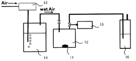
- FIG. 2 is a schematic configuration diagram of an apparatus for measuring the hydrogen sulfide concentration average value.
- the measurement sample 11 a sample that has been well pulverized in a mortar in a nitrogen glow box with a dew point of ⁇ 80 ° C. is used.
- a measurement sample 11 is sealed in a Schlenk bottle 12 of 0.1 g and 100 ml.
- air wet air
- humidified by passing the water tank 14 through the Schlenk bottle 12 is circulated at 500 ml / min.
- the temperature of the wet air is about 25 ° C. and the humidity is 80 to 90%.
- the supply amount of air is controlled by the flow meter 13.
- the gas discharged from the Schlenk bottle 12 within 1 minute to 1 minute 45 seconds after the start of distribution is collected from the gas collection unit 15 and used as a first sample gas for measurement.
- hydrogen sulfide is removed with a sodium hydroxide aqueous solution at the trap 16.
- TS-100 manufactured by Mitsubishi Chemical Analytech
- the sulfur content is quantified by the ultraviolet fluorescence method, and the hydrogen sulfide concentration of the sample gas is calculated.
- the sample gas was qualitatively analyzed with a gas chromatograph using an Agilent 6890 (with a sulfur selective detector (SIEVERS 355)), it was confirmed that the sulfur content was 99% or more of hydrogen sulfide gas.
- the discharged gas is also measured in the same manner as the first sample gas.
- the hydrogen sulfide concentration average value (ppm) is obtained from the hydrogen sulfide concentration and the measurement time.
- FIG. 3 shows an example of the relationship between the wet air circulation time and the hydrogen sulfide concentration. The curve is obtained by smoothing each measurement point, and the area (ppm ⁇ min) surrounded by the curve, the vertical axis, and the horizontal axis is divided by 60 minutes to obtain the hydrogen sulfide concentration average value (ppm).
- the shape of the solid electrolyte of the present invention is not particularly limited, and may be particulate or sheet-like.
- the electrolyte layer when forming the electrolyte layer, can be produced by applying a slurry containing the solid electrolyte or electrolyte precursor of the present invention as described later.
- the electrolyte layer of the present invention can be manufactured by heating under a predetermined heating condition described later.
- an electrolyte layer can also be manufactured using an electrostatic method.
- the volume-based average particle diameter (Mean Volume Diameter, hereinafter referred to as “particle diameter”) is preferably 0.01 ⁇ m or more and 500 ⁇ m or less.
- the particle size is preferably measured by a laser diffraction particle size distribution measuring method.
- the laser diffraction particle size distribution measuring method can measure the particle size distribution without drying the composition.
- a particle size distribution is measured by irradiating a particle group in a composition with a laser and analyzing the scattered light.
- the particle size is measured using a dried solid electrolyte or a sulfide-based glass that is a precursor thereof.
- the amount to be measured is added on the operation screen specified by the master sizer 2000 so that the laser scattering intensity corresponding to the particle concentration falls within the specified range (10 to 20%). If this range is exceeded, multiple scattering may occur, and an accurate particle size distribution may not be obtained. On the other hand, if the amount is less than this range, the S / N ratio deteriorates, and there is a possibility that accurate measurement cannot be performed.
- the laser scattering intensity is displayed based on the addition amount of the measurement target.
- the optimum amount of the object to be measured varies depending on the type of the ion conductive material, etc., it is generally about 0.01 to 0.05 g.
- the solid electrolyte of the present invention may be crystallized (glass ceramic) or amorphous (glass). If it is crystallized, it has the effect of increasing the ionic conductivity, and in the case of amorphous, it is softer than the crystal, so that the contact state between the solid electrolytes and the contact state with the active material and the conductive aid is improved. can do.
- X in the above formula (A) or (A ′) is preferably Br or Cl.
- the two temperature peaks are preferably observed by the following measurement method, and the two crystallization peaks are more preferably in the range of 150 ° C. or higher and 360 ° C. or lower.
- the width between the two crystallization peaks is preferably 20 to 150 ° C., more preferably 20 to 100 ° C.
- the crystallization temperature (peak) is about 20 mg of a solid electrolyte (glass) using a differential thermo-thermogravimetric apparatus (TGA / DSC1 manufactured by METTLER TOLEDO) or a differential scanning calorimeter (Diamond DSC manufactured by PerkinElmer). Can be determined by measuring at 10 ° C./min.
- the solid electrolyte (glass) has two crystallization peaks, the two crystallization peaks are in the range of 170 ° C. or higher and 330 ° C. or lower, and the width between the two crystallization peaks is 20 to 150 ° C. More preferably.
- the two crystallization peaks are more preferably in the range of 170 ° C. or higher and 330 ° C. or lower, and the width between the two crystallization peaks is more preferably 30 to 140 ° C.
- the solid electrolyte (glass) has two crystallization peaks, the two crystallization peaks are in the range of 175 ° C. to 320 ° C., and the width between the two crystallization peaks is 30 to 140 ° C. It is particularly preferred.
- the two crystallization peaks are particularly preferably in the range of 175 ° C. or more and 320 ° C. or less, and the width between the two crystallization peaks is particularly preferably 35 to 130 ° C.
- the solid electrolyte (glass) has two crystallization peaks, the two crystallization peaks are in the range of 180 ° C. to 310 ° C., and the width between the two crystallization peaks is 40 to 120 ° C. Most preferred.
- the method for producing the solid electrolyte of the present invention is not particularly limited.
- this invention is not limited to the solid electrolyte manufactured by these manufacturing methods.
- a solid electrolyte (glass) can be manufactured by making the raw material a and the compound containing a halogen element react by a predetermined method.
- (A) Raw material a As the raw material a, Li 2 S (lithium sulfide), P 2 S 3 (phosphorus trisulfide) , P 2 S 5 (phosphorus pentasulfide), SiS 2 (silicon sulfide), Li 4 SiO 4 (lithium orthosilicate) ), Al 2 S 3 (aluminum sulfide), simple phosphorus (P), simple sulfur (S), silicon (Si), GeS 2 (germanium sulfide), B 2 S 3 (diarsenic trisulfide), Li 3 PO 4 (lithium phosphate), Li 4 GeO 4 (lithium germanate), LiBO 2 (lithium metaborate), LiAlO 3 (lithium aluminate), Na 2 S (sodium sulfide), Na 4 GeO 4 (s
- Preferred raw materials a include a combination of Li 2 S and P 2 S 5 , phosphorus sulfide, a combination of elemental sulfur and elemental phosphorus, a combination of phosphorus sulfide and elemental sulfur, a combination of phosphorus sulfide, elemental sulfur and elemental phosphorus, and the like.
- the raw material a is a combination of lithium sulfide and diphosphorus pentasulfide will be described.
- Lithium sulfide can be used without any particular limitation, but high purity is preferred. Lithium sulfide can be produced, for example, by the method described in JP-A-7-330312, JP-A-9-283156, JP-A 2010-163356, and Japanese Patent Application No. 2009-238952.
- lithium hydroxide and hydrogen sulfide are reacted at 70 ° C. to 300 ° C. in a hydrocarbon-based organic solvent to produce lithium hydrosulfide, and then the reaction solution is dehydrosulfurized to form lithium sulfide.
- Can be synthesized Japanese Patent Laid-Open No. 2010-163356.
- lithium hydroxide and hydrogen sulfide are reacted at 10 ° C. to 100 ° C. in an aqueous solvent to produce lithium hydrosulfide, and then this reaction solution is dehydrosulfurized to synthesize lithium sulfide (special feature).
- Application 2009-238952 Application 2009-238952
- Lithium sulfide preferably has a total lithium oxide lithium salt content of 0.15% by mass or less, more preferably 0.1% by mass or less, and a content of lithium N-methylaminobutyrate.
- the content is preferably 0.15% by mass or less, more preferably 0.1% by mass or less.
- the total content of the lithium salt of sulfur oxide is 0.15% by mass or less, the solid electrolyte obtained by the melt quenching method or the mechanical milling method becomes a glassy electrolyte (fully amorphous).
- the total content of the lithium salt of sulfur oxide exceeds 0.15% by mass, the obtained electrolyte may become a crystallized product from the beginning.
- lithium N-methylaminobutyrate when the content of lithium N-methylaminobutyrate is 0.15% by mass or less, the deteriorated product of lithium N-methylaminobutyrate does not deteriorate the cycle performance of the lithium ion battery.
- lithium sulfide with reduced impurities when lithium sulfide with reduced impurities is used, a high ion conductive electrolyte can be obtained.
- lithium sulfide When lithium sulfide is produced based on the above-mentioned JP-A-7-330312 and JP-A-9-283156, it is preferable to purify lithium sulfide because it contains a lithium salt of sulfur oxide.
- lithium sulfide produced by the method for producing lithium sulfide described in JP-A-2010-163356 may be used without purification because it contains a very small amount of lithium oxide lithium salt and the like.
- a purification method for example, a purification method described in International Publication No. WO2005 / 40039 and the like can be mentioned. Specifically, the lithium sulfide obtained as described above is washed at a temperature of 100 ° C. or higher using an organic solvent.
- diphosphorus pentasulfide P 2 S 5
- P 2 S 5 diphosphorus pentasulfide
- Y represents an alkali metal such as lithium, sodium or potassium. Lithium and sodium are preferred, and lithium is particularly preferred.
- X is the same as X in the above formula (C).
- the compound containing a halogen element NaI, NaF, NaCl, NaBr, LiI, LiF, LiCl, or LiBr is preferable.
- M represents Li, B, Al, Si, P, S, Ge, As, Se, Sn, Sb, Te, Pb, or Bi. P or Li is particularly preferable.
- w is an arbitrary integer of 1 to 2
- x is an arbitrary integer in the range of 1 to 10.
- X is the same as X in the above formula (C).
- the compound containing a halogen element specifically, LiF, LiCl, LiBr, LiI , BCl 3, BBr 3, BI 3, AlF 3, AlBr 3, AlI 3, AlCl 3, SiF 4, SiCl 4, SiCl 3 , Si 2 Cl 6, SiBr 4 , SiBrCl 3, SiBr 2 Cl 2, SiI 4, PF 3, PF 5, PCl 3, PCl 5, POCl 3, PBr 3, POBr 3, PI 3, P 2 Cl 4, P 2 I 4 , SF 2 , SF 4 , SF 6 , S 2 F 10 , SCl 2 , S 2 Cl 2 , S 2 Br 2 , GeF 4 , GeCl 4 , GeBr 4 , GeI 4 , GeF 2 , GeCl 2 , GeBr 2, GeI 2, AsF 3, AsCl 3, AsBr 3, AsI 3, AsF 5, SeF 4, SeF 6, Se l 2, SeCl 4, Se 2 Br 2, SeBr 4, SnF 4, SnCl 4, Sn
- vitrification accelerator for reducing the glass transition temperature
- vitrification promoters include Li 3 PO 4 , Li 4 SiO 4 , Li 4 GeO 4 , Li 3 BO 3 , Li 3 AlO 3 , Li 3 CaO 3 , Li 3 InO 3, Na 3 PO 4 , Na
- inorganic compounds such as 4 SiO 4 , Na 4 GeO 4 , Na 3 BO 3 , Na 3 AlO 3 , Na 3 CaO 3 , and Na 3 InO 3 .
- the ratio (molar ratio) of lithium sulfide to phosphorous pentasulfide is 60:40 to 90:10, preferably 65:35 to 85:15 or 70:30 to 90:10, more preferably 67:33 to 83:17 or 72:28 to 88:12, particularly preferably 67:33 to 80:20 or 74:26 to 86:14. Particularly preferred is 70:30 to 80:20 or 75:25 to 85:15.
- the ratio (molar ratio) of lithium sulfide to diphosphorus pentasulfide is 72:28 to 78:22, or 77:23 to 83:17.
- the ratio (molar ratio) of the compound containing a halogen element and the sum of the molar amount of lithium sulfide and the phosphorous pentasulfide is 50:50 to 99: 1, preferably 55:45 to 95: 5, Preferably, it is 60:40 to 90:10.
- the ratio (molar ratio) of the molar amount of lithium sulfide and the total molar amount of phosphorous pentasulfide and the compound containing a halogen element is preferably 50:50 to 99: 1, more preferably 55:45 to 97: 3 or 70:30 to 98: 2, more preferably 60:40 to 96: 4 or 80:10 to 98: 2, particularly preferably 70:30 to 96: 4 or 80:20 to 98: 2. is there.
- a material obtained by mixing a compound containing lithium sulfide, diphosphorus pentasulfide and a halogen element in the above-mentioned mixing ratio is melt-quenched, mechanical milling (hereinafter, “mechanical milling” is appropriately referred to as “MM”), and in an organic solvent.
- MM mechanical milling
- a solid electrolyte (glass) is produced by a slurry method or a solid phase method in which the raw materials are reacted with each other.
- (A) Melting and quenching method The melting and quenching method is described, for example, in JP-A-6-279049 and WO2005 / 119706. Specifically, a predetermined amount of P 2 S 5 , Li 2 S, and a halogen-containing compound mixed in a mortar and pelletized are placed in a carbon-coated quartz tube and vacuum-sealed. After reacting at a predetermined reaction temperature, the solid electrolyte (glass) is obtained by putting it into ice and quenching.
- the reaction temperature is preferably 400 ° C to 1000 ° C, more preferably 800 ° C to 900 ° C.
- the reaction time is preferably 0.1 hour to 12 hours, more preferably 1 to 12 hours.
- the quenching temperature of the reactant is usually 10 ° C. or less, preferably 0 ° C. or less, and the cooling rate is usually about 1 to 10000 K / sec, preferably 10 to 10000 K / sec.
- MM method Mechanical milling method
- the MM method is described, for example, in JP-A-11-134937, JP-A-2004-348972, and JP-A-2004-348993.
- P 2 S 5 , Li 2 S and a halogen-containing compound are mixed in a predetermined amount in a mortar, and reacted for a predetermined time using, for example, various ball mills, so that the solid electrolyte (glass) is obtained. can get.
- the MM method using the above raw materials can be reacted at room temperature. Therefore, there is an advantage that a solid electrolyte (glass) having a charged composition can be obtained without thermal decomposition of the raw material. Further, the MM method has an advantage that it can be finely powdered simultaneously with the production of the solid electrolyte (glass).
- Various types such as a rotating ball mill, a rolling ball mill, a vibrating ball mill, and a planetary ball mill can be used for the MM method.
- the rotational speed may be several tens to several hundreds of revolutions / minute, and the treatment may be performed for 0.5 hours to 100 hours.
- balls of a ball mill may be used by mixing balls having different diameters.
- an organic solvent may be added to the raw material to form a slurry, and this slurry may be subjected to MM treatment. Further, as described in JP 2010-30889 A, the temperature in the mill during MM processing may be adjusted. It is preferable that the raw material temperature during MM treatment be 60 ° C. or higher and 160 ° C. or lower.
- (C) Slurry method The slurry method is described in WO2004 / 093099 and WO2009 / 047977. Specifically, a solid electrolyte (glass) is obtained by reacting a predetermined amount of P 2 S 5 particles, Li 2 S particles, and a halogen-containing compound in an organic solvent for a predetermined time.
- the halogen-containing compound is preferably dissolved in an organic solvent or is a particle.
- the slurry containing the raw material may be reacted while being circulated between the bead mill and the reaction vessel.
- the reaction can proceed efficiently.
- a polar solvent for example, methanol, diethyl carnate, acetonitrile
- the reaction temperature is preferably 80 ° C. 20 ° C. or more or less, and more preferably 20 ° C. or higher 60 ° C. or less.
- the reaction time is preferably 16 hours or more 1 hour or less, and more preferably not more than 2 hours or more 14 hours.
- the amount of the organic solvent is preferably such that the raw materials lithium sulfide, diphosphorus pentasulfide and the halogen-containing compound become a solution or slurry by the addition of the organic solvent.
- the amount of the raw material (total amount) added to 1 liter of the organic solvent is about 0.001 kg or more and 1 kg or less.
- they are 0.005 kg or more and 0.5 kg or less, Most preferably, they are 0.01 kg or more and 0.3 kg or less.
- the organic solvent is not particularly limited, but an aprotic organic solvent is particularly preferable.
- the aprotic organic solvent include aprotic apolar organic solvents (for example, hydrocarbon organic solvents), aprotic polar organic compounds (for example, amide compounds, lactam compounds, urea compounds, organic sulfur compounds, rings)
- a formula organophosphorus compound or the like can be suitably used as a single solvent or as a mixed solvent.
- a saturated hydrocarbon, an unsaturated hydrocarbon, or an aromatic hydrocarbon can be used as the hydrocarbon organic solvent.
- saturated hydrocarbon include hexane, pentane, 2-ethylhexane, heptane, decane, and cyclohexane.
- unsaturated hydrocarbon include hexene, heptene, cyclohexene and the like.
- Aromatic hydrocarbons include toluene, xylene, decalin, 1,2,3,4-tetrahydronaphthalene and the like. Of these, toluene and xylene are particularly preferable.
- Some of the raw materials for the solid electrolyte of the present invention are soluble in the organic solvent, such as phosphorus tribromide, and are suitable for production using a slurry method.
- the organic solvent such as phosphorus tribromide
- lithium sulfide does not dissolve in an organic solvent, but phosphorus tribromide dissolves in an organic solvent. Therefore, when lithium sulfide, diphosphorus pentasulfide and phosphorus bromide are used as raw materials, all the raw materials are dissolved in the organic solvent. Since the reactivity is higher than when not dissolved, the reaction time can be shortened, and a high purity solid electrolyte (glass) with little unreacted residue can be obtained.
- the hydrocarbon solvent is preferably dehydrated in advance.
- the water content is preferably 100 ppm by weight or less, and particularly preferably 30 ppm by weight or less.
- ketones such as acetone and methyl ethyl ketone
- ethers such as tetrahydrofuran
- alcohols such as ethanol and butanol
- esters such as ethyl acetate
- halogenated hydrocarbons such as dichloromethane and chlorobenzene.
- Solid phase method The solid phase method is described in, for example, “HJ Deiseroth, et.al., Angew.Chem.Int.Ed.2008, 47, 755-758”. Specifically, a solid electrolyte (glass) is obtained by mixing a predetermined amount of a compound containing P 2 S 5 , Li 2 S and halogen in a mortar and heating at a temperature of 100 to 900 ° C.
- Manufacturing conditions such as temperature conditions, processing time, and charge for the melt quenching method, MM method, slurry method and solid phase method can be appropriately adjusted according to the equipment used.
- the method for producing the solid electrolyte (glass) the MM method, the slurry method or the solid phase method is preferable. Since it can be produced at a low cost, the MM method and the slurry method are more preferable, and the slurry method is particularly preferable.
- the order of mixing the composition of the final precursors may be in the range described above.
- the raw materials Li 2 S, P 2 S 5 and LiBr may be mixed and then milled; after Li 2 S and P 2 S 5 are milled, LiBr is added. Further milling may be performed; after LiBr and P 2 S 5 are milled, Li 2 S may be added and further milled; after Li 2 S and LiBr are milled, P 2 S 5 is added and further milled. Also good.
- the mixture was treated milled mixture of Li 2 S and LiBr may be performed further milling treatment after having mixed the mixture was milled and mixed with LiBr and P 2 S 5.
- two or more different methods may be combined when two or more mixing processes are performed.
- Li 2 S and P 2 S 5 may be processed by mechanical milling
- LiBr may be mixed and processed by a solid phase method
- Li 2 S and LiBr may be processed by a solid phase method and P 2.
- S and 5 LiBr were mixed and subjected to melt-quenching process
- the solid electrolyte (glass) may be prepared by performing the slurry process.
- the solid electrolyte does not have a peak in the first peak region in 31 P-NMR, It is preferable that the peak appears.
- the crystallized solid electrolyte (glass ceramics) can be obtained by heat-treating the solid electrolyte (glass) (sulfide glass). Heating is preferably performed in an environment having a dew point of ⁇ 40 ° C. or lower, more preferably in an environment having a dew point of ⁇ 60 ° C. or lower.
- the pressure at the time of heating may be a normal pressure or a reduced pressure.
- the atmosphere may be in the air or an inert atmosphere. Further, it may be heated in a solvent as described in JP-A 2010-186744.
- the heating temperature is preferably not less than the glass transition temperature (Tg) of the solid electrolyte (glass) and not more than the crystallization temperature (Tc) of the solid electrolyte (glass) + 100 ° C. If the heating temperature is lower than the Tg of the solid electrolyte (glass), the production time may be very long. On the other hand, when (Tc + 100 ° C.) is exceeded, impurities or the like may be contained in the obtained solid electrolyte (glass ceramic), and the ionic conductivity may be lowered.
- Tg glass transition temperature
- Tc crystallization temperature
- the heating temperature is more preferably (Tg + 5 ° C.) or more and (Tc + 90 ° C.) or less, and further preferably (Tg + 10 ° C.) or more and (Tc + 80 ° C.) or less.
- the heating temperature is 150 ° C. or higher and 360 ° C. or lower, preferably 160 ° C. or higher and 350 ° C. or lower, more preferably 180 ° C. or higher and 310 ° C. or lower, more preferably 180 ° C. or higher and 290 ° C. or lower, Especially preferably, it is 190 degreeC or more and 270 degreeC or less.
- the peak temperature on the low temperature side is Tc, and heat treatment is performed between the low temperature side Tc and the high temperature side second crystallization peak (Tc2).
- the crystallization temperature (peak) can be specified by differential thermal-thermogravimetry as described above.
- Tc measured at a rate close to the heating rate for heat treatment. Therefore, when the treatment is performed at a temperature raising rate other than the example, the optimum heat treatment temperature changes, but it is desirable to perform the heat treatment under the above-mentioned conditions with reference to Tc measured at the temperature raising rate for heat treatment.
- the heating time is preferably 0.005 minutes or more and 10 hours or less. More preferably, it is 0.005 minutes or more and 5 hours or less, and particularly preferably 0.01 minutes or more and 3 hours or less. If it is less than 0.005 minutes, the electrolyte of the present invention contains a large amount of solid electrolyte (glass), and the ionic conductivity may be lowered. If it exceeds 10 hours, impurities or the like may be generated in the crystallized solid electrolyte of the present invention, and the ionic conductivity may be lowered.
- the temperature raising method may be raised slowly to a predetermined temperature or heated rapidly.
- the second manufacturing method is a method in which a halogen compound is further added to the solid electrolyte (glass) of the first manufacturing method described above and heated at a predetermined temperature and for a predetermined time.
- the solid electrolyte (glass) and the halogen compound are preferably mixed by MM treatment or the like.
- the manufacturing method of the solid electrolyte (glass) and the heating time, heating temperature, etc. of the material in which the halogen compound is added to the solid electrolyte (glass) are the same as those in the first manufacturing method, and the description thereof will be omitted.
- a halogen compound the compound containing the same halogen element as the 1st manufacturing method mentioned above can be used.
- the total amount of the halogen-containing compound used as the raw material for the solid electrolyte (glass) and the amount of the halogen compound mixed in the solid electrolyte (glass) is the same as in the first production method. This is the same as the amount of the compound containing a halogen element used as a raw material for the solid electrolyte (glass).
- the ratio of the compound containing a halogen element which is a raw material of the solid electrolyte (glass) and the halogen compound mixed in the solid electrolyte (glass) is not particularly limited.
- a solid electrolyte is manufactured by heating the compound containing the electrolyte precursor 1 and the halogen element at a predetermined temperature and for a predetermined time.
- the electrolyte precursor 1 is preferably a compound that does not have a peak at 75.0 ppm to 80.0 ppm (first peak region) in 31 P-NMR and satisfies the following formula (F).
- Li a M b P c S d (F) In the formula (F), M, a, b, c and d are the same as the above formula (A).
- the electrolyte precursor 1 preferably has a peak in the region of 81.0 ppm or more and 85.0 ppm or less in 31 P-NMR.
- the third manufacturing method differs from the first manufacturing method in that the electrolyte precursor 1 is manufactured without adding a compound containing a halogen element to the raw material of the solid electrolyte (glass), and the electrolyte precursor 1 and It is a point which manufactures by mixing with the compound containing a halogen element, and heating for a predetermined temperature and predetermined time. That is, except that the electrolyte precursor 1 [solid electrolyte (glass)] is produced only from the raw material a, and the mixture of the electrolyte precursor 1 and the halogen-containing compound is heated at a predetermined temperature and for a predetermined time, This is the same as the manufacturing method. Therefore, since the raw material a, the compound containing a halogen element, the manufacturing method of the electrolyte precursor 1, and the manufacturing conditions of the solid electrolyte are the same as those of the first manufacturing method, the description thereof is omitted.
- the ratio (molar ratio) of lithium sulfide to diphosphorus pentasulfide is 60:40 to 90:10, preferably 65:35 to 85: 15 or 70:30 to 90:10, more preferably 67:33 to 83:17 or 72:28 to 88:12, and particularly preferably 67:33 to 80:20 or 74:26 to 86: 14. Particularly preferred is 70:30 to 80:20 or 75:25 to 85:15. Most preferably, it is 72:28 to 78:22, or 77:23 to 83:17.
- the ratio (molar ratio) between the electrolyte precursor 1 and the halogen-containing compound is 50:50 to 99: 1, preferably 55:45 to 95: 5, particularly preferably 60:40 to 90:10.
- the ratio (molar ratio) of the electrolyte precursor 1 to the halogen-containing compound is preferably 50:50 to 99: 1, more preferably 55:45 to 97: 3 or 70:30 to 98: 2.
- the ratio is preferably 60:40 to 96: 4 or 80:10 to 98: 2, and particularly preferably 70:30 to 96: 4 or 80:20 to 98: 2.
- the solid electrolyte of the present invention is hardly hydrolyzed and has high ionic conductivity, it is suitable as a constituent material of a battery such as a solid electrolyte layer.
- the solid electrolyte of the present invention is mixed with a binder (binder), a positive electrode active material, a negative electrode active material, a conductive additive, or a halogen-containing compound similar to the above-described production method, an organic solvent, or the like. It may be used as an inclusion.
- the electrolyte-containing material can be used as a constituent material of a battery such as a positive electrode, an electrolyte layer, and a negative electrode, and a material for forming a member (layer) constituting the battery.
- the electrolyte-containing material of the present invention only needs to contain the solid electrolyte of the present invention.
- binders include polytetrafluoroethylene (PTFE), polyvinylidene fluoride (PVdF), fluorine-containing resins such as fluorine rubber, thermoplastic resins such as polypropylene and polyethylene, ethylene-propylene-dienemer (EPDM), sulfonated EPDM, Natural butyl rubber (NBR) or the like can be used alone or as a mixture of two or more.
- aqueous dispersion of cellulose or styrene butadiene rubber (SBR) that is an aqueous binder may be used.
- the positive electrode active material a material capable of inserting and releasing lithium ions, and a material known as a positive electrode active material in the battery field can be used.
- LiMn 2-Z Ni Z O 4 LiMn 2-Z Co Z O 4 ( wherein 0
- positive electrode active materials include, for example, elemental sulfur (S), titanium sulfide (TiS 2 ), molybdenum sulfide (MoS 2 ), iron sulfide (FeS, FeS 2 ), copper sulfide (CuS) in the sulfide system.
- Nickel sulfide (Ni 3 S 2 ), lithium sulfide (Li 2 S), organic disulfide compounds, carbon sulfide compounds, sulfur, and the like can be used.
- S and Li 2 S having a high theoretical capacity can be used.
- organic disulfide compounds examples include organic disulfide compounds and carbon sulfide compounds.
- X is a substituent
- n and m are each independently an integer of 1 to 2
- p and q are each independently an integer of 1 to 4.
- Z is —S— or —NH—, respectively, and n is an integer of 2 to 300 repetitions.
- the negative electrode active material a material capable of inserting and desorbing lithium ions, and a material known as a negative electrode active material in the battery field can be used.
- carbon materials specifically artificial graphite, graphite carbon fiber, resin-fired carbon, pyrolytic vapor-grown carbon, coke, mesocarbon microbeads (MCMB), furfuryl alcohol resin-fired carbon, polyacene, pitch-based carbon
- fibers vapor-grown carbon fibers, natural graphite, and non-graphitizable carbon. Or it may be a mixture thereof.
- it is artificial graphite.
- an alloy combined with a metal itself such as metallic lithium, metallic indium, metallic aluminum, metallic silicon, or other elements or compounds can be used as the negative electrode material.
- a metal itself such as metallic lithium, metallic indium, metallic aluminum, metallic silicon, or other elements or compounds.
- silicon, tin, and lithium metal having a high theoretical capacity are preferable.
- the conductive auxiliary agent only needs to have conductivity.
- the conductivity is preferably 1 ⁇ 10 3 S / cm or more, and more preferably 1 ⁇ 10 5 S / cm or more.
- the conductive assistant include substances selected from carbon materials, metal powders and metal compounds, and mixtures thereof. Specific examples of conductive aids include carbon, nickel, copper, aluminum, indium, silver, cobalt, magnesium, lithium, chromium, gold, ruthenium, platinum, beryllium, iridium, molybdenum, niobium, osnium, rhodium, tungsten and zinc.
- the carbon material include carbon black such as ketjen black, acetylene black, denka black, thermal black and channel black, graphite, carbon fiber, activated carbon and the like. These can be used alone or in combination of two or more. Among these, acetylene black, denka black, and ketjen black having high electron conductivity are preferable.
- the electrolyte layer (sheet) of the present invention includes at least one of the above-described solid electrolyte of the present invention and an electrolyte-containing material containing the same.
- the above-described binder or the like may be contained depending on the purpose of use, and other electrolytes may be contained.
- the other electrolyte is a polymer-based solid electrolyte, an oxide-based solid electrolyte, or the electrolyte precursor 1 described above.
- the polymer-based solid electrolyte is not particularly limited.
- materials used as a polymer electrolyte such as a fluororesin, polyethylene oxide, polyacrylonitrile, polyacrylate, a derivative thereof, and a copolymer, can be given.
- fluororesin examples include those containing, as a structural unit, vinylidene fluoride (VdF), hexafluoropropylene (HFP), tetrafluoroethylene (TFE), and derivatives thereof.
- VdF vinylidene fluoride
- HFP hexafluoropropylene
- TFE tetrafluoroethylene
- a homopolymer such as polyvinylidene fluoride (PVdF), polyhexafluoropropylene (PHFP), polytetrafluoroethylene (PTFE), or a copolymer of VdF and HFP (hereinafter, this copolymer is referred to as “ P (VdF-HFP) ”may be used, and binary copolymers and terpolymers.
- oxide-based solid electrolyte examples include crystals having a perovskite structure such as LiN, LISICON, Thio-LISICON, La 0.55 Li 0.35 TiO 3 , LiTi 2 P 3 O 12 having a NASICON type structure, These crystallized electrolytes can be used.
- the electrolyte layer according to another aspect of the present invention is an electrolyte layer produced using the solid electrolyte or the electrolyte-containing material of the present invention.
- the electrolyte layer of the present invention may be manufactured, for example, by applying a slurry containing the solid electrolyte of the present invention, a binder and a solvent, or may be manufactured by an electrostatic screen printing method using a granular solid electrolyte. Good.
- the electrolyte layer of the present invention is suitable for a constituent layer of a battery.
- at least one of the positive electrode layer, the electrolyte layer, and the negative electrode layer includes the solid electrolyte of the present invention.
- Each layer can be manufactured by a known method.
- the battery of the present invention is heated by the predetermined heating condition. It can also be manufactured.
- the positive electrode layer preferably contains a positive electrode active material, an electrolyte, and a conductive additive. Moreover, the binder may be included. About these specific examples, it is the same as that of the example of the electrolyte containing material mentioned above.
- the ratios of the positive electrode active material, the electrolyte, the conductive auxiliary agent and the like are not particularly limited, and known ratios can be used.
- the thickness of the positive electrode layer is preferably 0.01 mm or more and 10 mm or less.
- the positive electrode layer can be produced by a known method. For example, it can be produced by a coating method or an electrostatic method (electrostatic spray method, electrostatic screen method, etc.).
- the negative electrode layer preferably contains a negative electrode active material, an electrolyte, and a conductive additive. Moreover, the binder may be included. About these specific examples, it is the same as that of the example of the electrolyte containing material mentioned above. The formation method and thickness are the same as in the case of the positive electrode.
- the electrolyte layer contains an electrolyte and may contain a binder. About these specific examples, it is the same as that of the example of the electrolyte containing material mentioned above.
- the solid electrolyte in the electrolyte layer is preferably fused.
- the fusion means that a part of the solid electrolyte particles is dissolved, and the dissolved part is integrated with other solid electrolyte particles.
- the electrolyte layer may be a solid electrolyte plate.
- the thickness of the electrolyte layer is preferably 0.001 mm or more and 1 mm or less. Since the electrolyte and the binder are the same as those of the positive electrode layer, description thereof is omitted.
- the battery of the present invention preferably uses a current collector in addition to the positive electrode layer, the electrolyte layer, and the negative electrode layer.
- a known current collector can be used.
- a layer coated with Au or the like that reacts with a sulfide-based solid electrolyte such as Au, Pt, Al, Ti, or Cu can be used.
- a second aspect of the battery of the present invention is a battery in which at least one of the positive electrode layer, the electrolyte layer, and the negative electrode layer is manufactured using at least one of the solid electrolyte and the electrolyte-containing material of the present invention.
- at least one of the positive electrode layer, the electrolyte layer, and the negative electrode layer may be manufactured using the solid electrolyte or the electrolyte-containing material of the present invention, and the others are the same as those in the first aspect described above.
- this invention is not limited to a lithium ion battery.
- an alkali metal electrolyte such as sodium or a divalent cation electrolyte such as magnesium may be used. In these cases, the effects of the present invention can be obtained.
- the sample measurement method is as follows. (1) Measurement of 31 P-NMR spectrum A JNM-CMXP302 NMR apparatus manufactured by JEOL Ltd. was equipped with a 5 mm CP / MAS probe and measured at room temperature. The 31 P-NMR spectrum was measured using a single pulse method at a 90 ° pulse of 4 ⁇ s and a magic angle rotation number of 8.6 kHz. Chemical shifts were measured by using ammonium hydrogen phosphate as an external standard (1.3 ppm). The measurement range is 0 ppm to 150 ppm.
- the hydrogen sulfide concentration of the sample gas was calculated.
- the sample gas was qualitatively analyzed with a gas chromatograph using an Agilent 6890 (with a sulfur selective detector (SIEVERS 355)), and it was confirmed that the sulfur content was 99% or more of the hydrogen sulfide gas. From the start of distribution 5 minutes to 5 minutes 45 seconds, from the start of distribution 10 minutes to 10 minutes 45 seconds, from the start of distribution 20 minutes to 20 minutes 45 seconds, from the start of distribution 60 minutes to 60 minutes 45 seconds from the Schlenk bottle The discharged gas was also measured in the same manner as the first sample gas. The average value (ppm) of hydrogen sulfide concentration was determined from the hydrogen sulfide concentration and measurement time.
- Production and purification of lithium sulfide were carried out in the same manner as in the examples of International Publication WO2005 / 040039A1. Specifically, it is as follows. (1) Production of lithium sulfide A 10-liter autoclave equipped with a stirring blade was charged with 3326.4 g (33.6 mol) of N-methyl-2-pyrrolidone (NMP) and 287.4 g (12 mol) of lithium hydroxide at 300 rpm. The temperature was raised to 130 ° C. After the temperature rise, hydrogen sulfide was blown into the liquid at a supply rate of 3 liters / minute for 2 hours.
- NMP N-methyl-2-pyrrolidone
- this reaction solution was heated under a nitrogen stream (200 cc / min) to dehydrosulfide a part of the reacted hydrogen sulfide.
- water produced as a by-product due to the reaction between the hydrogen sulfide and lithium hydroxide started to evaporate, but this water was condensed by the condenser and extracted out of the system.
- the temperature of the reaction solution rose, but when the temperature reached 180 ° C., the temperature increase was stopped and the temperature was kept constant. After the dehydrosulfurization reaction was completed (about 80 minutes), the reaction was completed to obtain lithium sulfide.
- the planetary ball mill was rotated at a low speed (100 rpm) to sufficiently mix lithium sulfide and diphosphorus pentasulfide. Thereafter, the rotational speed of the planetary ball mill was gradually increased to 370 rpm. Mechanical milling was performed for 20 hours at a rotational speed of the planetary ball mill at 370 rpm. As a result of evaluating the mechanically milled white yellow powder by X-ray measurement, it was confirmed that the powder was vitrified (sulfide glass). 31 P-NMR measurement showed a main peak at 83.0 ppm.
- the ionic conductivity was 1.3 ⁇ 10 ⁇ 4 S / cm. Moreover, the average value of hydrogen sulfide concentration was 20.2 ppm.
- Table 1 shows the 31 P-NMR measurement results, ionic conductivity ⁇ , and hydrogen sulfide concentration average value of the obtained sample.
- Table 2 shows the glass transition temperature (Tg) and the crystallization temperature (Tc). The glass transition temperature (Tg) and the crystallization temperature (Tc) were measured at 10 ° C./min with a differential scanning calorimeter (Diamond DSC manufactured by PerkinElmer).
- Table 1 shows the 31 P-NMR measurement results, ionic conductivity ⁇ , and hydrogen sulfide concentration average value of the obtained sample, and Table 2 shows Tg and Tc.
- Table 1 shows the 31 P-NMR measurement results, ionic conductivity ⁇ , and hydrogen sulfide concentration average value of the obtained sample, and Table 2 shows Tg and Tc.
- a sulfide-based glass (solid electrolyte) was obtained in the same manner as in Production Example 2, except that 0.600 g of the sulfide-based glass obtained in Production Example 2 and 0.400 g of lithium iodide were used as raw materials.
- the results of 31 P-NMR measurement, ionic conductivity ⁇ , and hydrogen sulfide concentration average value of the obtained sample are shown in Table 1, and Tg, Tc, and Tc2 are shown in Table 2.
- Example 4 0.5 g of the solid electrolyte (sulfide-based glass) obtained in Example 1 was put into a SUS container and set in an oven controlled at a temperature of 210 ° C. in advance. The mixture was allowed to stand for 2 hours and then air-cooled to obtain a sulfide-based solid electrolyte.
- 31 P-NMR measurement showed peaks at 90 ppm and 77 ppm, and the intensity ratio (I 2 / I 1 ) was 2.5. Although peaks were also observed at around 105 ppm and around 45 ppm, they were very small, less than a quarter of the 77 ppm peak.
- Table 3 shows the ionic conductivity ⁇ and hydrogen sulfide concentration average value of the obtained solid electrolyte.
- Example 5 0.5 g of the sulfide-based glass obtained in Example 1 was quickly sandwiched between two stainless steel plates previously heated to 210 ° C. in an oven controlled at a temperature of 210 ° C. and left for 10 minutes. By sandwiching it between heated metal plates, the sample reaches 210 ° C. in about 2 minutes. In Example 4, it takes several tens of minutes for the sample to reach a predetermined temperature.
- Table 3 shows the 31 P-NMR measurement results, ionic conductivity ⁇ , and hydrogen sulfide concentration average value of the solid electrolyte obtained by this operation.
- FIG. 4 shows 31 P-NMR spectra of the solid electrolyte obtained in Example 1 and the solid electrolyte obtained in Example 5.
- Example 6 A solid electrolyte was produced in the same manner as in Example 5 except that the heat treatment conditions were 250 ° C. and 10 minutes. Table 3 shows the 31 P-NMR measurement results, ionic conductivity ⁇ , and hydrogen sulfide concentration average value of the obtained sample.
- Example 7 A solid electrolyte was produced in the same manner as in Example 4 except that the sulfide-based glass obtained in Example 2 was used. Table 3 shows the 31 P-NMR measurement results, ionic conductivity ⁇ , and hydrogen sulfide concentration average value of the obtained sample.
- Example 8 A solid electrolyte was produced in the same manner as in Example 5 except that the sulfide-based glass obtained in Example 2 was used. Table 3 shows the 31 P-NMR measurement results, ionic conductivity ⁇ , and hydrogen sulfide concentration average value of the obtained sample.
- Example 9 A solid electrolyte was produced in the same manner as in Example 5 except that the sulfide-based glass obtained in Example 3 was used. Table 3 shows the 31 P-NMR measurement results, ionic conductivity ⁇ , and hydrogen sulfide concentration average value of the obtained sample.
- Comparative Example 1 The operation was performed in the same manner as in Example 4 except that the sulfide-based glass obtained in Production Example 2 was used and the heat treatment temperature was 300 ° C.
- Table 3 shows the 31 P-NMR measurement results, ionic conductivity ⁇ , and hydrogen sulfide concentration average value of the obtained sample.
- Comparative Example 2 The operation was performed in the same manner as in Example 4 except that the sulfide-based glass obtained in Production Example 3 was used and the heat treatment temperature was 300 ° C.
- Table 3 shows the 31 P-NMR measurement results, ionic conductivity ⁇ , and hydrogen sulfide concentration average value of the obtained sample.
- All of the sulfide-based solid electrolytes of Examples 1 to 9 had a very high ionic conductivity ⁇ of 2 ⁇ 10 ⁇ 4 S / cm or more.
- all of the sulfide-based solid electrolytes of Examples 1 to 9 are excellent in hydrolysis resistance, there is a possibility that they can be used in a higher dew point environment than before.
- a sulfide-based solid electrolyte excellent in hydrolysis resistance has not been known so far.
- the sulfide-based solid electrolyte of Comparative Example 1 is excellent in hydrolysis resistance, but has low ionic conductivity and is not suitable for battery use.
- the sulfide-based solid electrolyte of Comparative Example 2 shows high ionic conductivity, but has poor hydrolysis resistance, and it is necessary to keep the working environment at a low dew point.
- the mixed powder, 10 zirconia balls having a diameter of 10 mm, and a planetary ball mill (Fritsch: Model No. P-7) are put into an alumina pot and completely sealed, and the alumina pot is filled with argon. Argon atmosphere.
- the planetary ball mill was rotated at a low speed (100 rpm) to sufficiently mix lithium sulfide and diphosphorus pentasulfide. Thereafter, the rotational speed of the planetary ball mill was gradually increased to 370 rpm.
- Mechanical milling was performed at 370 rpm for 20 hours with a planetary ball mill rotating speed to obtain a white yellow powder as a solid electrolyte.
- the crystallization temperature (Tc) was measured by ion conductivity (before heat treatment) and TG-DTA (thermogravimetry). The results are shown in Table 4.
- the crystallization temperature was measured using TGA-DSC1 manufactured by METTLER TOLEDO.
- the first peak position (appears as a shoulder peak) is 77.7 ppm
- the second peak position is 88.0 ppm
- the other peak positions are 107.7 ppm
- I2 / I1 is 2.57
- Ic / I1 is 0.00. 27.
- the powder XRD diffraction pattern of the obtained solid electrolyte is shown in FIG.
- the diffraction pattern is obtained by forming the obtained solid electrolyte sample into a shape having a cross section of 10 mm ⁇ , attaching the sample piece to a sample jig for anaerobic measurement, and placing the sample piece contained in the jig into a Rigaku Smart lab device.
- X-ray beam (CuK ⁇ : ⁇ 1.54184).
- Tc crystallization temperature
- All of the sulfide-based solid electrolytes of Examples 10 to 15 had a very high ion conductivity ⁇ of 1 ⁇ 10 ⁇ 4 S / cm or more. Moreover, since it is excellent in hydrolysis resistance, it may be usable in a higher dew point environment than before. Thus, a sulfide-based solid electrolyte excellent in hydrolysis resistance has not been known so far. Further, the obtained XRD pattern is different from the solid electrolyte patterns reported so far, and can be said to be a novel solid electrolyte. Even if the amount of LiBr added was changed, the peak position did not change.
- the sulfide-based solid electrolyte of Comparative Example 3 is excellent in hydrolysis resistance, but has low ionic conductivity and is not suitable for battery use.
- the sulfide-based solid electrolyte of Comparative Example 4 exhibits high ionic conductivity.
- the hydrolysis resistance is poor and the working environment must be kept at a low dew point.
- Example 16 Evaluation of hydrogen sulfide concentration average value
- the result was 7.4 ppm.
- Tc crystallization temperature
- the planetary ball mill was rotated at a low speed (100 rpm) and lithium sulfide, diphosphorus pentasulfide and phosphorous tribromide were sufficiently mixed. Thereafter, the rotational speed of the planetary ball mill was gradually increased to 370 rpm. Mechanical milling was performed at a rotational speed of the planetary ball mill at 370 rpm for 20 hours to obtain powder.
- the obtained solid electrolyte was measured at 10 ° C./min with a thermogravimetric apparatus (TGA / DSC1 manufactured by METTLER TOLEDO), the crystallization peak was 220 ° C. The second crystallization peak appeared at around 287 ° C.
- the position of the first peak (which appeared as a shoulder peak) was 78.3 ppm
- the second peak position was 88.0 ppm
- the positions of the other peaks were 107.9 ppm
- I2 / I1 was 2.40
- Ic / I1 was 0.42.
- the powder XRD diffraction pattern of the obtained solid electrolyte is shown in FIG.
- the composition of this compound is Li 3.56 PS 3.95 Br 0.36 .
- the hydrogen sulfide concentration average value was evaluated by the method described above.
- the average hydrogen sulfide generation concentration was 38.3 ppm, which was the same as that of Comparative Example 3, and was a relatively small generation amount.
- the solid electrolyte and the electrolyte-containing material of the present invention are suitable as constituent materials for batteries such as a positive electrode layer, an electrolyte layer, and a negative electrode.
Landscapes
- Chemical & Material Sciences (AREA)
- Engineering & Computer Science (AREA)
- Chemical Kinetics & Catalysis (AREA)
- General Chemical & Material Sciences (AREA)
- Electrochemistry (AREA)
- Manufacturing & Machinery (AREA)
- Physics & Mathematics (AREA)
- Materials Engineering (AREA)
- Inorganic Chemistry (AREA)
- General Physics & Mathematics (AREA)
- Condensed Matter Physics & Semiconductors (AREA)
- Geochemistry & Mineralogy (AREA)
- Dispersion Chemistry (AREA)
- Life Sciences & Earth Sciences (AREA)
- Crystallography & Structural Chemistry (AREA)
- Ceramic Engineering (AREA)
- Organic Chemistry (AREA)
- Spectroscopy & Molecular Physics (AREA)
- Secondary Cells (AREA)
- Conductive Materials (AREA)
- Glass Compositions (AREA)
- Battery Electrode And Active Subsutance (AREA)
Abstract
Description
この加水分解性を抑制する技術が特許文献2に提案されている。しかしながら、本技術では加水分解性が低減する代わりにイオン伝導度が大きく低下するという問題がある。
1.構成成分として、アルカリ金属元素、リン、硫黄及びハロゲンを含む固体電解質。
2.前記アルカリ金属元素がリチウムである1に記載の固体電解質。
3.1P-NMRスペクトルにおいて、75.0ppm以上80.0ppm以下であるピーク領域にピークを有する1又は2に記載の固体電解質。
4.31P-NMRスペクトルにおいて、86.0ppm以上92.0ppm以下であるピーク領域にピークを有する1~3のいずれかに記載の固体電解質。
5.31P-NMRスペクトルにおいて、75.0ppm以上80.0ppm以下である第一ピーク領域に第一ピークを有し、
前記第一ピーク領域、及び86.0ppm以上92.0ppm以下の領域である第二ピーク領域以外の領域にあるピークの強度比が、前記第一ピークに対し0.5以下である1~4のいずれかに記載の固体電解質。
6.前記第一ピーク領域及び第二ピーク領域に、それぞれピークを有する5に記載の固体電解質。
7.前記第一ピーク(I1)に対する、前記第二ピーク領域にある第二ピーク(I2)のピーク強度比(I2/I1)が1~10である6に記載の固体電解質。8.イオン伝導度が5×10-4S/cm以上である5~7のいずれかに記載の固体電解質。
9.加水分解試験による硫化水素濃度平均値が200ppm以下である5~8のいずれかに記載の固体電解質。
10.イオン伝導度が3×10⁻⁴S/cm以上である1~4のいずれかに記載の固体電解質。
11.加水分解試験による硫化水素濃度平均値が200ppm以下である1~4、10のいずれかに記載の固体電解質。
12.下記式(A’)に示す組成を有する1~11のいずれかに記載の固体電解質。
LaMbPcSdXe…(A’)
(式中、Lはアルカリ金属を示し、MはB,Al,Si,Ge,As,Se,Sn,Sb,Te,PbもしくはBi、又はこれらの組合せを示し、XはI,Cl,BrもしくはF又はこれらの組合せを示す。a~eは、0<a≦12、0≦b≦0.2、c=1,0<d≦9、0<e≦9を満たす。)
13.前記bが0である12に記載の固体電解質。
14.前記dが4である12に記載の固体電解質。
15.前記Xが、I、Br又はClである12~14のいずれかに記載の固体電解質。
16.結晶構造を有する12~15のいずれかに記載の固体電解質。
17.前記Xが、Br又はClであり、非晶質である12~14のいずれかに記載の固体電解質。
18.硫化リチウムと硫化リン、硫黄とリン、硫化リンと硫黄、又は硫化リンと硫黄とリンと、
下記式(E’)で表される化合物と、
を原料とする12~17のいずれかに記載の固体電解質。
MwXx…(E’)
(式中、MはLi,B,Al,Si,P,S,Ge,As,Se,Sn,Sb,Te,Pb又はBiを示し、XはF,Cl,Br又はIを示す。wは1~2の整数を示し、xは1~10の整数を示す。)
19.前記MがPであり、前記XがBr、I又はClである18に記載の固体電解質。
20.前記MがLiであり、前記XがBr、I又はClである18に記載の固体電解質。
21.非晶質であり、示差熱-熱重量測定において、結晶化ピークを2つ有する12~15、17~20のいずれかに記載の固体電解質。
22.前記2つの結晶化ピークが150℃以上360℃以下の範囲にある21に記載の固体電解質。
23.前記2つの結晶化ピーク間の幅が20~100℃である21又は22に記載の固体電解質。
24.非晶質である12~15、17~23のいずれかに記載の固体電解質を150℃以上360℃以下で加熱することにより得られる固体電解質。
25.上記21~23のいずれかに記載の固体電解質を、前記2つの結晶化ピークで示される温度の間の温度で加熱して得られる固体電解質。
26.構成成分としてアルカリ金属元素を含み、
粉末X線回折(CuKα:λ=1.5418Å)において、少なくとも2θ=16.3±0.3deg,21.3±0.3deg,33.1±0.8degに回折ピークを有する固体電解質。
27.構成成分としてアルカリ金属元素を含み、
粉末X線回折(CuKα:λ=1.5418Å)において、少なくとも2θ=16.3±0.3deg,21.3±0.3deg,33.1±0.5degに回折ピークを有する固体電解質。
28.構成成分としてアルカリ金属元素を含み、
粉末X線回折(CuKα:λ=1.5418Å)において、2θ=15.6±0.3deg,16.3±0.3deg,21.3±0.3deg,30.1±0.3deg,31.5±0.3deg,33.1±0.3degに回折ピークを有する固体電解質。
29.構成成分としてアルカリ金属元素を含み、
粉末X線回折(CuKα:λ=1.5418Å)において、2θ=15.6±0.3deg,16.3±0.3deg,21.3±0.3deg,30.1±0.5deg,31.5±0.3deg,33.1±0.3degに回折ピークを有する固体電解質。
30.構成成分としてアルカリ金属元素を含み、
粉末X線回折(CuKα:λ=1.5418Å)において、2θ=15.6±0.3deg,16.3±0.3deg,21.3±0.3deg,29.8±0.3deg,31.5±0.3deg,33.1±0.3degに回折ピークを有する固体電解質。
31.構成成分としてアルカリ金属元素を含み、
粉末X線回折(CuKα:λ=1.5418Å)において、2θ=15.6±0.3deg,16.3±0.3deg,21.3±0.3deg,31.5±0.3deg,32.6±0.3degに回折ピークを有する固体電解質。
32.前記アルカリ金属元素が、リチウムである26~31のいずれかに記載の固体電解質。
33.イオン伝導度が3×10⁻⁴S/cm以上である26~32のいずれかに記載の固体電解質。
34.加水分解試験による硫化水素濃度平均値が200ppm以下である25~33のいずれかに記載の固体電解質。
35.構成成分として硫黄元素、リン元素及びハロゲン元素から選択される元素を1以上含む26~34のいずれかに記載の固体電解質。
36.構成成分としてハロゲン元素を20モル%以下含む26~35のいずれかに記載の固体電解質。
37.前記ハロゲン元素を15モル%以下含む36に記載の固体電解質。
38.上記1~4,10~25のいずれかに記載の固体電解質を含む電解質含有物。
39.上記1~4,10~25のいずれかに記載の固体電解質及び38に記載の電解質含有物の少なくとも1つを含む電解質層。
40.上記1~4,10~25のいずれかに記載の固体電解質及び38の電解質含有物の少なくとも1つを用いて製造された電解質層。
41.正極層、電解質層及び負極層の少なくとも一つが、1~4,10~25のいずれかに記載の固体電解質及び38の電解質含有物の少なくとも1つを含む電池。
42.正極層、電解質層及び負極層の少なくとも一つが、1~4,10~25のいずれかに記載の固体電解質及び38の電解質含有物の少なくとも1つを用いて製造された電池。
43.上記5~9のいずれかに記載の固体電解質を含む電解質含有物。
44.上記5~9のいずれかに記載の固体電解質及び43に記載の電解質含有物の少なくとも1つを含む電解質層。
45.上記5~9のいずれかに記載の固体電解質及び43の電解質含有物の少なくとも1つを用いて製造された電解質層。
46.正極層、電解質層及び負極層の少なくとも一つが、5~9のいずれかに記載の固体電解質及び43の電解質含有物の少なくとも1つを含む電池。
47.正極層、電解質層及び負極層の少なくとも一つが、5~9のいずれかに記載の固体電解質及び43の電解質含有物の少なくとも1つを用いて製造された電池。
48.上記26~37のいずれかに記載の固体電解質を含む電解質含有物。
49.上記26~37のいずれかに記載の固体電解質を原料とする電解質含有物。
50.上記26~37のいずれかに記載の固体電解質及び48又は49に記載の電解質含有物の少なくとも1つを含む電解質層。
51.上記26~37のいずれかに記載の固体電解質及び48又は49の電解質含有物の少なくとも1つを用いて製造された電解質層。
52.正極層、電解質層及び負極層の少なくとも一つが、26~37のいずれかに記載の固体電解質及び48又は49の電解質含有物の少なくとも1つを含む電池。
53.正極層、電解質層及び負極層の少なくとも一つが、26~37のいずれかに記載の固体電解質及び48又は49の電解質含有物の少なくとも1つを用いて製造された電池。
本発明の第1の固体電解質は、31P-NMRスペクトルにおいて、75.0ppm以上80.0ppm以下であるピーク領域(以下、第一ピーク領域という。)にピーク(以下、第一のピークという。)を有することが好ましい。このピーク条件により特定される固体電解質は、加水分解しにくく、高いイオン伝導度を有する。
明確な極大点がなくピークトップの位置が分からない場合、ショルダーピークのピーク位置は、75.0ppm以上80.0ppm以下のピーク領域における微分値の絶対値が最も小さくなるところとする。
第二のピークも同様にショルダーピークであってもよく、明確な極大点がなくピークトップの位置が分からない場合、ショルダーピークのピーク位置は、第二ピーク領域における微分値の絶対値が最も小さくなるところとする。
上記ピーク条件により特定される固体電解質は、加水分解しにくく、高いイオン伝導度を有する。
ピーク強度は、ベースラインからピークトップまでの高さとする。
上記回折ピークにより特定される固体電解質は、加水分解しにくく、高いイオン伝導度を有する。
本発明の第2の固体電解質は、粉末X線回折(CuKα:λ=1.5418Å)において、より好ましくは少なくとも2θ=16.3±0.3deg,21.3±0.3deg,33.1±0.3degに回折ピークを有し、さらに好ましくは少なくとも2θ=15.6±0.3deg,16.3±0.3deg,21.3±0.3deg,30.1±0.5deg,31.5±0.3deg,33.1±0.3degに回折ピークを有し、特に好ましくは少なくとも2θ=15.6±0.3deg,16.3±0.3deg,21.3±0.3deg,30.1±0.3deg又は29.8±0.3deg,31.5±0.3deg,33.1±0.3degに回折ピークを有する。
例えば、2θ=15.6±0.3deg,16.3±0.3deg,21.3±0.3deg,25.1±0.3deg,30.1±0.3deg,31.5±0.3deg,33.1±0.3degに回折ピークを有していてもよい。
また、本発明の第2の固体電解質は、アルカリ金属元素を必須の構成成分とし、好ましくはさらにリン元素、硫黄元素及びハロゲン元素の少なくとも1つ、より好ましくは硫黄元素を構成成分として含む。
また、本発明の第2の固体電解質は、ハロゲン元素を含むことが好ましく、その含有量は好ましくは20モル%以下、より好ましくは15モル%以下である。
上記ハロゲンは、F、Cl、Br及びIから選択される1つのハロゲン原子であることが好ましく、Cl、Br又はIであることがより好ましく、特に、Br又はIであることが好ましい。
LaMbPcSdXe…(A)
式(A)において、Lは、アルカリ金属であり、リチウムとナトリウムが好ましく、特にリチウムが好ましい。
BfZngSihCuiGajGek…(B)
式(B)において、f~kはそれぞれ各元素の組成比を示す。f、g、h、i、j、kは、それぞれ0以上1以下であり、かつ、f+g+h+i+j+k=1である。式(B)は、B、Zn、Si、Cu、Ga及びGeから選択される1種の元素、又は、これらのうち2種以上の元素の組み合わせを表す。
式(B)において、f、i及びjが0である場合、即ち、ZngSihGek(g、h、kは0以上1以下であり、かつg+h+k=1)が好ましい。
FlClmBrnIo…(C)
好ましくは、lとmが0である場合、即ち、BrnIo(n、oはそれぞれ0以上1以下であり、n+o=1)である。
Xは、F、Cl、Br及びIから選択される1つのハロゲン原子であることが好ましく、特に、Br又はIであることが好ましい。
好ましくは、bは0であり、より好ましくは、a、c、d及びeの比(a:c:d:e)がa:c:d:e=1~9:1:3~7:0.05~3、さらに好ましくは、a:c:d:e=2~4.5:1:3.5~5:0.1~1.5である。
LaMbPcSdXe…(A’)
式(A’)において、Lは、アルカリ金属であり、リチウムとナトリウムが好ましく、特にリチウムが好ましい。
式(A’)において、Mは下記式(B’)で表される元素を表す。
BfAlgSihGeiAsjSekSnlSbmTenPboBip…(B’)
式(B’)において、f~pはそれぞれ各元素の組成比を示す。f、g、h、i、j、k、l、m、o,pは、それぞれ0以上1以下であり、かつ、f+g+h+i+j+k+l+m+n+o+p=1である。式(B’)は、B,Al,Si,P,S,Ge,As,Se,Sn,Sb,Te,Pb及びBiから選択される1種の元素、又は、2種以上の元素の組み合わせを表す。
式(A’)において、Xは下記式(C’)を表す。
FsItCluBrv…(C’)
式(C’)において、s、t、u及びvはそれぞれ各元素の組成比を示す。s、t、u及びvは、それぞれ0以上1以下であり、かつ、s+t+u+v=1である。式(C’)は、F、Cl、Br及びIから選択される1種のハロゲン元素、又は、2種以上のハロゲン元素の組み合わせを表す。
好ましくは、sとtが0である場合、即ち、CluBrv(u、vはそれぞれ0以上1以下であり、u+v=1)である。より好ましくは、sとtとuが0である場合、即ち、Brである場合である。
Xは、F、Cl、Br及びIから選択される1つのハロゲン原子であることが好ましく、特に、I,Br又はClであることが好ましく、より好ましくはBrである。
式(A’)において、a~eはそれぞれ各元素の組成比を示し、0<a≦12、0≦b≦0.2、c=1,0<d≦9、0<e≦9を満たす。
好ましくは、bは0であり、より好ましくは、a、c、d及びeの比(a:c:d:e)がa:c:d:e=1~9:1:3~7:0.05~3、さらに好ましくは、a:c:d:e=2~6.5:1:3.5~5:0.1~1.5である。最も好ましくは、a:c:d:e=2~6.5:1:3.5~4.95:0.1~1.5である。
dは4であると好ましい。
尚、イオン伝導度は高ければ高いほど好ましいが、例えば、上限として5×10⁻²S/cmを挙げることができる。
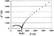
まず、試料を断面10mmφ(断面積S=0.785cm2)、高さ(L)0.1~0.3cmの形状に成形する。その試料片の上下から電極端子を取り、交流インピーダンス法により測定し(周波数範囲:5MHz~0.5Hz、振幅:10mV)、Cole-Coleプロットを得る。図1にCole-Coleプロットの一例を示す。高周波側領域に観測される円弧の右端付近で、-Z’’(Ω)が最小となる点での実数部Z’(Ω)を電解質のバルク抵抗R(Ω)とし、以下式に従い、イオン伝導度σ(S/cm)を計算する。
R=ρ(L/S)
σ=1/ρ
本願ではリードの距離を約60cmとして測定した。
一般に硫化物系固体電解質は、加水分解すると硫化水素を発生するが、本発明の固体電解質では、加水分解を抑制できるので、分解時に発生する硫化水素が少なくなる。
図2は、硫化水素濃度平均値の測定装置の概略構成図である。
測定試料11は、露点-80℃の環境の窒素グローボックス内にて乳鉢でよく粉砕したものを用いる。測定試料11を0.1g、100mlのシュレンク瓶12内に封入する。
次に、シュレンク瓶12内に、水槽14を通過させることにより加湿した空気(ウェットエア)を500ml/分で流通させる。尚、ウェットエアの温度は、25℃程度、湿度は、80~90%とする。また、空気の供給量は流量計13で制御する。
流通開始1分後~1分45秒後の間にシュレンク瓶12から排出されたガスをガス採集部15から捕集して測定用の第一サンプルガスとする。尚、採集時以外のガスは、トラップ16で水酸化ナトリウム水溶液にて硫化水素を除去する。
三菱化学アナリテック製TS-100を用いて、紫外蛍光法により硫黄分を定量して、サンプルガスの硫化水素濃度を算出する。尚、サンプルガスをアジレント6890(硫黄選択検出器(SIEVERS355)付)を用いてガスクロマトグラフにて定性分析したところ、硫黄分はその99%以上硫化水素ガスになっていることを確認している。
流通開始5分後~5分45秒後、流通開始10分後~10分45秒後、流通開始20分後~20分45秒後、流通開始60分後~60分45秒後にシュレンク瓶から排出されたガスについても、第一サンプルガスと同様に測定する。
硫化水素濃度と測定時間から硫化水素濃度平均値(ppm)を求める。
図3にウェットエア流通時間と硫化水素濃度の関係の一例を示す。曲線は各測定点をスムージングしたもので、この曲線と縦軸、横軸で囲まれた面積(ppm・分)を時間60分で除することにより、硫化水素濃度平均値(ppm)を求める。
粒子状の場合、電解質層を形成する際に、後述するように本発明の固体電解質又は電解質前駆体を含むスラリーを塗布することにより電解質層を製造することができる。電解質前駆体を用いて電解質シートを製造する場合には、電解質前駆体を用いて電解質層を形成後、後述する所定の加熱条件により加熱して本発明の電解質層を製造することもできる。
また、静電法を用いて電解質層を製造することもできる。
本願において、粒径の測定方法は、レーザー回折式粒度分布測定方法により行うことが好ましい。レーザー回折式粒度分布測定方法は、組成物を乾燥せずに粒度分布を測定することができる。レーザー回折式粒度分布測定方法では、組成物中の粒子群にレーザーを照射して、その散乱光を解析することで粒度分布を測定する。
本願では、乾燥した固体電解質又はその前駆体である硫化物系ガラスを用いて粒径を測定する。
まず、装置の分散槽に脱水処理されたトルエン(和光純薬製、製品名:特級)110mlを入れ、さらに分散剤として脱水処理されたターシャリーブチルアルコール(和光純薬製、特級)を6%添加する。
上記混合物を十分混合した後、測定対象である「乾燥した固体電解質又はその前駆体」を添加して粒子径を測定する。測定対象の添加量は、マスターサイザー2000で規定されている操作画面で、粒子濃度に対応するレーザー散乱強度が規定の範囲内(10~20%)に収まるように加減して加える。この範囲を超えると多重散乱が発生し、正確な粒子径分布を求めることができなくなるおそれがある。また、この範囲より少ないとSN比が悪くなり、正確な測定ができないおそれがある。マスターサイザー2000では、測定対象の添加量に基づき、レーザー散乱強度が表示されるので、上記レーザー散乱強度に入る添加量を見つけるとよい。
測定対象の添加量はイオン伝導性物質の種類等により最適量は異なるが、概ね0.01g~0.05g程度である。
結晶化温度(ピーク)は、示差熱-熱重量測定装置(メトラートレド社製TGA/DSC1)、又は示差走査熱量測定装置(パーキンエルマー社製Diamond DSC)を使用し、固体電解質(ガラス)約20mgを10℃/分で測定して特定できる。
また、2つの結晶化ピークが170℃以上330℃以下の範囲にあることがさらに好ましく、また2つの結晶化ピーク間の幅が30~140℃であることがさらに好ましい。
また、固体電解質(ガラス)は、2つの結晶化ピークがあり、2つの結晶化ピークが175℃以上320℃以下の範囲にあり、かつ2つの結晶化ピーク間の幅が30~140℃であることが特に好ましい。
また、2つの結晶化ピークが175℃以上320℃以下の範囲にあることが特に好ましく、また、2つの結晶化ピーク間の幅が35~130℃であることが特に好ましい。また、固体電解質(ガラス)は、2つの結晶化ピークがあり、2つの結晶化ピークが180℃以上310℃以下の範囲にあり、かつ2つの結晶化ピーク間の幅が40~120℃であることが最も好ましい。
固体電解質(ガラス)は、原料aとハロゲン元素を含む化合物とを所定の方法により反応させることにより製造することができる。
(a)原料a
原料aとしては、Li2S(硫化リチウム)、P2S3(三硫化二リン)、P2S5(五硫化二リン)、SiS2(硫化珪素)、Li4SiO4(オルト珪酸リチウム)、Al2S3(硫化アルミニウム)、単体リン(P)、単体の硫黄(S)、シリコン(Si)、GeS2(硫化ゲルマニウム)、B2S3(三硫化二砒素)、Li3PO4(燐酸リチウム)、Li4GeO4(ゲルマン酸リチウム)、LiBO2(メタホウ酸リチウム)、LiAlO3(リチウムアルミネート)、Na2S(硫化ナトリウム)、Na4GeO4(ゲルニウム酸ナトリウム)、Na4SiO4(オルト珪酸ナトリウム)、Na3PO4(リン酸ナトリウム)、NaBO2(メタホウ酸ナトリウム)、NaAlO3(アルミン酸ナトリウム)等を用いることができる。これらは2種以上混合して使用してもよい。
好ましい原料aとしては、Li2SとP2S5の組み合わせ、硫化リン、単体硫黄と単体リンの組み合わせ、硫化リンと単体硫黄の組み合わせ、硫化リンと単体硫黄と単体リンの組み合わせ等が挙げられる。
以下、原料aが硫化リチウム及び五硫化二リンの組み合わせである場合について説明する。
また、水溶媒中で水酸化リチウムと硫化水素とを10℃~100℃で反応させて、水硫化リチウムを生成し、次いでこの反応液を脱硫化水素化することにより硫化リチウムを合成できる(特願2009-238952)。
一方、特開2010-163356に記載の硫化リチウムの製法で製造した硫化リチウムは、硫黄酸化物のリチウム塩等の含有量が非常に少ないため、精製せずに用いてもよい。
好ましい精製法としては、例えば、国際公開WO2005/40039号に記載された精製法等が挙げられる。具体的には、上記のようにして得られた硫化リチウムを、有機溶媒を用い、100℃以上の温度で洗浄する。
ハロゲン元素を含む化合物としては、下記式(E)に示す化合物を用いることができ、1つの化合物を用いてもよく、複数の化合物を用いてもよい。
Y-X…(E)
Xは、上記式(C)のXと同様である。
ハロゲン元素を含む化合物としては、NaI,NaF,NaCl,NaBr、LiI、LiF、LiCl又はLiBrが好ましい。
Mw-Xx…(E’)
式(E’)において、Mは、Li,B,Al,Si,P,S,Ge,As,Se,Sn,Sb,Te,Pb又はBiを示す。特にP又はLiが好ましい。wは1~2の任意の整数、xは1~10の範囲の任意の整数である。
Xは、上記式(C)のXと同様である。
以下、原料aとして、硫化リチウム及び五硫化二リンを用いた固体電解質(ガラス)の製造方法について説明する。
硫化リチウムと五硫化二リンの割合(モル比)は、60:40~90:10、好ましくは65:35~85:15又は70:30~90:10であり、さらに好ましくは67:33~83:17又は72:28~88:12であり、特に好ましくは67:33~80:20又は74:26~86:14である。特により好ましくは、70:30~80:20又は75:25~85:15である。最も好ましくは、硫化リチウムと五硫化二リンの割合(モル比)は、72:28~78:22、又は77:23~83:17である。
硫化リチウムのモル量と五硫化二リンのモル量の合計とハロゲン元素を含む化合物の割合(モル比)は、50:50~99:1が好ましく、より好ましくは55:45~97:3又は70:30~98:2であり、さらに好ましくは60:40~96:4又は80:10~98:2であり、特に好ましくは70:30~96:4又は80:20~98:2である。尚、硫化リチウムのモル量と五硫化二リンのモル量の合計とハロゲン元素を含む化合物は、MM処理等により混合してから加熱処理することが好ましい。
溶融急冷法は、例えば、特開平6-279049、WO2005/119706に記載されている。具体的には、P2S5とLi2Sとハロゲンを含む化合物とを所定量乳鉢にて混合しペレット状にしたものを、カーボンコートした石英管中に入れ真空封入する。所定の反応温度で反応させた後、氷中に投入し急冷することにより、固体電解質(ガラス)が得られる。
反応時間は、好ましくは0.1時間~12時間、より好ましくは、1~12時間である。
MM法は、例えば、特開平11-134937、特開2004-348972、特開2004-348973に記載されている。
具体的には、P2S5とLi2Sとハロゲンを含む化合物とを所定量乳鉢にて混合し、例えば、各種ボールミル等を使用して所定時間反応させることにより、固体電解質(ガラス)が得られる。
上記原料を用いたMM法は、室温で反応させることができる。そのため、原料の熱分解が起らず、仕込み組成の固体電解質(ガラス)を得ることができるという利点がある。
また、MM法では固体電解質(ガラス)の製造と同時に、微粉末化できるという利点もある。
MM法の条件としては、例えば、遊星型ボールミル機を使用した場合、回転速度を数十~数百回転/分とし、0.5時間~100時間処理すればよい。
また、特開2010-90003に記載されているように、ボールミルのボールは異なる径のボールを混合して使用してもよい。
また、特開2009-110920や特開2009-211950に記載されているように、原料に有機溶媒を添加してスラリー状にし、このスラリーをMM処理してもよい。
また、特開2010-30889に記載のようにMM処理の際のミル内の温度を調整してもよい。
MM処理時の原料温度が、60℃以上160℃以下になるようにすることが好ましい。
スラリー法は、WO2004/093099、WO2009/047977に記載されている。
具体的には、所定量のP2S5粒子とLi2S粒子とハロゲンを含む化合物とを有機溶媒中で所定時間反応させることにより、固体電解質(ガラス)が得られる。
ハロゲンを含む化合物は、有機溶媒に溶解するか、又は粒子であることが好ましい。
また、WO2009/047977に記載されているように、原料の硫化リチウムを予め粉砕しておくと効率的に反応を進行させることができる。
また、特願2010-270191に記載されているように、原料の硫化リチウムの比表面積を大きくするために溶解パラメーターが9.0以上の極性溶媒(例えば、メタノール、ジエチルカーネート、アセトニトリル)に所定時間浸漬してもよい。
反応時間は、好ましくは1時間以上16時間以下、より好ましくは、2時間以上14時間以下である。
非プロトン性有機溶媒としては、非プロトン性の非極性有機溶媒(例えば、炭化水素系有機溶媒)、非プロトン性の極性有機化合物(例えば、アミド化合物,ラクタム化合物,尿素化合物,有機イオウ化合物,環式有機リン化合物等)を、単独溶媒として、又は、混合溶媒として、好適に使用することができる。
飽和炭化水素としては、ヘキサン、ペンタン、2-エチルヘキサン、ヘプタン、デカン、シクロヘキサン等が挙げられる。
不飽和炭化水素しては、ヘキセン、ヘプテン、シクロヘキセン等が挙げられる。
芳香族炭化水素としては、トルエン、キシレン、デカリン、1,2,3,4-テトラヒドロナフタレン等が挙げられる。
これらのうち、特にトルエン、キシレンが好ましい。
例えば、硫化リチウムは有機溶媒に溶解しないが、三臭化リンは有機溶媒に溶解するため、硫化リチウム、五硫化二リン及び臭化リンを原料に用いる場合には、全ての原料が有機溶媒に溶解しない場合よりも反応性が高くなるため、反応時間を短くでき、未反応残留物の少ない高純度の固体電解質(ガラス)を得ることができる。
固相法は、例えば、「H-J.Deiseroth,et.al.,Angew.Chem.Int.Ed.2008,47,755-758」に記載されている。具体的には、P2S5とLi2Sとハロゲンを含む化合物を所定量乳鉢にて混合し、100~900℃の温度で加熱することにより、固体電解質(ガラス)が得られる。
固体電解質(ガラス)の製造法としては、MM法、スラリー法又は固相法が好ましい。低コストで製造可能であることから、MM法、スラリー法がより好ましく、特にスラリー法が好ましい。
上記の他、2回以上混合処理を行う場合、2種以上の異なる方法を組み合わせてもよい。例えばLi2SとP2S5をメカニカルミリングで処理した上でLiBrを混合し固相法で処理を行ってもよく、Li2SとLiBrを固相法で処理を行ったものとP2S5とLiBrとを溶融急冷処理を行ったものを混合し、スラリー法を行うことで固体電解質(ガラス)を製造してもよい。
結晶化固体電解質(ガラスセラミックス)は、上記固体電解質(ガラス)(硫化物ガラス)を加熱処理することにより得られる。加熱は、露点-40℃以下の環境下で行うことが好ましく、より好ましくは露点-60℃以下の環境下で行うことが好ましい。
加熱時の圧力は、常圧であってもよく、減圧下であってもよい。
雰囲気は、空気中であってもよく、不活性雰囲気下であってもよい。
さらに、特開2010-186744に記載されているように溶媒中で加熱してもよい。
加熱温度は、より好ましくは、(Tg+5℃)以上、(Tc+90℃)以下、さらに好ましくは、(Tg+10℃)以上、(Tc+80℃)以下である。
例えば、加熱温度は、150℃以上360℃以下であり、好ましくは160℃以上350℃以下であり、より好ましくは180℃以上310℃以下であり、さらに好ましくは180℃以上290℃以下であり、特に好ましくは190℃以上270℃以下である。
また、熱物性の測定により2つのピークがある場合は、低温側のピーク温度をTcとし、低温側のTcと高温側の第2結晶化ピーク(Tc2)との間で熱処理することが好ましい。
尚、結晶化温度等は昇温速度等により変化することがあるため、熱処理する昇温速度に近い速度で測定したTcを基準とする必要がある。従って、実施例以外の昇温速度で処理する場合は、最適な熱処理温度は変化するが、熱処理する昇温速度で測定されたTcを基準として上記条件にて熱処理することが望ましい。
第二の製造方法は、上述した第一の製造方法の固体電解質(ガラス)に、さらに、ハロゲン化合物を添加して、所定温度及び所定時間加熱する方法である。
固体電解質(ガラス)とハロゲン化合物は、MM処理等により混合しておくことが好ましい。固体電解質(ガラス)の製造方法や、固体電解質(ガラス)にハロゲン化合物を添加した材料の加熱時間、加熱温度等は、第一の製造方法と同様であるので、その説明は省略する。
ハロゲン化合物としては、上述した第一の製造方法と同じハロゲン元素を含む化合物が使用できる。
尚、第二の製造方法において、固体電解質(ガラス)の原料として使用するハロゲン元素を含む化合物の量と、固体電解質(ガラス)に混合するハロゲン化合物の量の合計は、第一の製造方法における固体電解質(ガラス)の原料として使用するハロゲン元素を含む化合物の量と同様である。固体電解質(ガラス)の原料であるハロゲン元素を含む化合物と、固体電解質(ガラス)に混合するハロゲン化合物との割合は特に限定しない。
第三の製造方法では、電解質前駆体1とハロゲン元素を含む化合物を所定温度及び所定時間加熱することにより固体電解質を製造する。
電解質前駆体1は、31P-NMRにおいて75.0ppm以上80.0ppm以下(第一ピーク領域)にピークを有さず、かつ下記式(F)を満たす化合物であることが好ましい。
LiaMbPcSd…(F)
(式(F)において、M,a,b,c及びdは上記式(A)と同様である。)
即ち、原料aのみにより電解質前駆体1[固体電解質(ガラス)]を製造し、電解質前駆体1とハロゲン元素を含む化合物との混合物を所定温度及び所定時間加熱している他は、第一の製造方法と同様である。従って、原料a、ハロゲン元素を含む化合物、電解質前駆体1の製造方法、及び固体電解質の製造条件は、上記第一の製造方法と同様であるので、その説明を省略する。
本発明の固体電解質は、バインダー(結着剤)、正極活物質、負極活物質、導電助剤、又は、上述した製造方法と同様のハロゲン元素を含む化合物や有機溶媒等と混合して、電解質含有物として使用してもよい。電解質含有物は、正極、電解質層、負極等、電池の構成材料として、及び電池を構成する部材(層)を形成するための材料として使用できる。
バインダーとしては、ポリテトラフルオロエチレン(PTFE)、ポリフッ化ビニリデン(PVdF)、フッ素ゴム等の含フッ素樹脂、或いはポリプロピレン、ポリエチレン等の熱可塑性樹脂、エチレン-プロピレン-ジエンマー(EPDM)、スルホン化EPDM、天然ブチルゴム(NBR)等を単独で、又は2種以上の混合物として用いることができる。また、水系バインダーであるセルロース系やスチレンブタジエンゴム(SBR)の水分散体等を用いることもできる。
例えば、V2O5、LiCoO2、LiNiO2、LiMnO2、LiMn2O4、Li(NiaCobMnc)O2(ここで、0<a<1、0<b<1、0<c<1、a+b+c=1)、LiNi1-YCoYO2、LiCo1-YMnYO2、LiNi1-YMnYO2(ここで、0≦Y<1)、Li(NiaCobMnc)O4(0<a<2、0<b<2、0<c<2、a+b+c=2)、LiMn2-ZNiZO4、LiMn2-ZCoZO4(ここで、0<Z<2)、LiCoPO4、LiFePO4、酸化ビスマス(Bi2O3)、鉛酸ビスマス(Bi2Pb2O5)、酸化銅(CuO)、酸化バナジウム(V6O13)、LixCoO2,LixNiO2,LixMn2O4,LixFePO4,LixCoPO4,LixMn1/3Ni1/3Co1/3O2,LixMn1.5Ni0.5O2等の酸化物が挙げられる。それ以外の正極活物質としては、例えば、硫化物系では、単体硫黄(S)、硫化チタン(TiS2)、硫化モリブデン(MoS2)、硫化鉄(FeS、FeS2)、硫化銅(CuS)及び硫化ニッケル(Ni3S2)、硫化リチウム(Li2S)、有機ジスルフィド化合物、カーボンスルフィド化合物、硫黄等が使用できる。好ましくは、高い理論容量を有するS、Li2Sが使用できる。


例えば、炭素材料、具体的には、人造黒鉛、黒鉛炭素繊維、樹脂焼成炭素、熱分解気相成長炭素、コークス、メソカーボンマイクロビーズ(MCMB)、フルフリルアルコール樹脂焼成炭素、ポリアセン、ピッチ系炭素繊維、気相成長炭素繊維、天然黒鉛及び難黒鉛化性炭素等が挙げられる。又はその混合物でもよい。好ましくは、人造黒鉛である。
導電助剤としては、炭素材料、金属粉末及び金属化合物から選択される物質や、これらの混合物が挙げられる。
導電助剤の具体例としては、炭素、ニッケル、銅、アルミニウム、インジウム、銀、コバルト、マグネシウム、リチウム、クロム、金、ルテニウム、白金、ベリリウム、イリジウム、モリブデン、ニオブ、オスニウム、ロジウム、タングステン及び亜鉛からなる群より選択される少なくとも1つの元素を含む物質が好ましい。より好ましくは、導電性が高い炭素単体、炭素、ニッケル、銅、銀、コバルト、マグネシウム、リチウム、ルテニウム、金、白金、ニオブ、オスニウム又はロジウムを含む金属単体、混合物又は化合物である。
なかでも、電子伝導性が高いアセチレンブラック、デンカブラック、ケッチェンブラックが好適である。
ポリマー系固体電解質は、特に制限はない。例えば、特開2010-262860に開示されているように、フッ素樹脂、ポリエチレンオキサイド、ポリアクリロニトリル、ポリアクリレートやこれらの誘導体、共重合体等の、ポリマー電解質として用いられる材料が挙げられる。
本発明の電解質層は、例えば、本発明の固体電解質、バインダー及び溶媒を含むスラリーを塗布して製造してもよく、また、粒状の固体電解質を用いて静電スクリーン印刷法により製造してもよい。
本発明の電池の第一の態様は、正極層、電解質層及び負極層の少なくとも一つが、本発明の固体電解質を含む。各層の製造は、公知の方法により製造することができる。
尚、上述した電解質前駆体を用いて正極層、負極層又は電解質層を製造する場合には、電解質前駆体を用いて層を形成後、上記所定の加熱条件により加熱して本発明の電池を製造することもできる。
正極層において、正極活物質、電解質、導電助剤等の割合は、特に制限は無く公知の割合を用いることができる。
正極層の厚さは、0.01mm以上10mm以下であることが好ましい。
正極層は、公知の方法により製造することができる。例えば、塗布法、静電法(静電スプレー法、静電スクリーン法等)により製造することができる。
電解質層の固体電解質は、融着していていることが好ましい。ここで、融着とは、固体電解質粒子の一部が溶解し、溶解した部分が他の個体電解質粒子と一体化することを意味する。
電解質層の厚さは、0.001mm以上1mm以下であることが好ましい。
尚、電解質及びバインダーは正極層と同様であることからその説明を省略する。
本態様では、正極層、電解質層及び負極層の少なくとも一つが本発明の固体電解質又は電解質含有物を用いて製造されておればよく、その他については、上述した第一の態様と同様である。
(1)31P-NMRスペクトルの測定
日本電子(株)製JNM-CMXP302NMR装置に、5mmCP/MASプローブを取り付け室温で行った。31P-NMRスペクトルは、シングルパルス法を用い、90°パルス4μs、マジック角回転の回転数8.6kHzで測定した。
化学シフトは、リン酸水素アンモニウムを外部標準(1.3ppm)として用いることにより測定した。測定範囲は、0ppm~150ppmである。
試料を断面10mmφ(断面積S=0.785cm2)、高さ(L)0.1~0.3cmの形状に成形し、その試料片の上下から電極端子を取り、交流インピーダンス法により測定し(周波数範囲:5MHz~0.5Hz、振幅:10mV)、Cole-Coleプロットを得た。高周波側領域に観測される円弧の右端付近で、-Z’’(Ω)が最小となる点での実数部Z’(Ω)を電解質のバルク抵抗R(Ω)とし、以下式に従い、イオン伝導度σ(S/cm)を計算した。
R=ρ(L/S)
σ=1/ρ
本願ではリードの距離を約60cmとして測定した。
図2に示す測定装置を使用した。
測定試料を、露点-80℃の環境の窒素グローボックス内にて乳鉢でよく粉砕した。測定試料0.1gを100mlシュレンク瓶内に封入した。
次に、シュレンク瓶内に一旦水中に通した空気(ウェットエア)を500ml/分で流通させた。ウェットエアの温度は25℃、湿度は80~90%であった。
流通開始1分後~1分45秒後の間にシュレンク瓶から排出されたガスを捕集して第一サンプルガスとし、三菱化学アナリテック製TS-100を用いて、紫外蛍光法により硫黄分を定量して、サンプルガスの硫化水素濃度を算出した。尚、サンプルガスをアジレント6890(硫黄選択検出器(SIEVERS355)付)を用いてガスクロマトグラフにて定性分析したところ、硫黄分はその99%以上硫化水素ガスになっていることを確認した。
流通開始5分後~5分45秒後、流通開始10分後~10分45秒後、流通開始20分後~20分45秒後、流通開始60分後~60分45秒後にシュレンク瓶から排出されたガスについても、第一サンプルガスと同様に測定した。
硫化水素濃度と測定時間から硫化水素濃度平均値(ppm)を求めた。
硫化リチウムの製造及び精製は、国際公開公報WO2005/040039A1の実施例と同様に行った。具体的には、下記のとおりである。
(1)硫化リチウムの製造
撹拌翼のついた10リットルオートクレーブにN-メチル-2-ピロリドン(NMP)3326.4g(33.6モル)及び水酸化リチウム287.4g(12モル)を仕込み、300rpm、130℃に昇温した。昇温後、液中に硫化水素を3リットル/分の供給速度で2時間吹き込んだ。
続いて、この反応液を窒素気流下(200cc/分)昇温し、反応した硫化水素の一部を脱硫化水素化した。昇温するにつれ、上記硫化水素と水酸化リチウムの反応により副生した水が蒸発を始めたが、この水はコンデンサにより凝縮し系外に抜き出した。水を系外に留去すると共に反応液の温度は上昇するが、180℃に達した時点で昇温を停止し、一定温度に保持した。脱硫化水素反応が終了後(約80分)反応を終了し、硫化リチウムを得た。
上記(1)で得られた500mLのスラリー反応溶液(NMP-硫化リチウムスラリー)中のNMPをデカンテーションした後、脱水したNMP100mLを加え、105℃で約1時間撹拌した。その温度のままNMPをデカンテーションした。さらにNMP100mLを加え、105℃で約1時間撹拌し、その温度のままNMPをデカンテーションし、同様の操作を合計4回繰り返した。デカンテーション終了後、窒素気流下230℃(NMPの沸点以上の温度)で硫化リチウムを常圧下で3時間乾燥した。得られた硫化リチウム中の不純物含有量を測定した。
製造例1で製造した硫化リチウムを用いて、国際公開公報WO07/066539の実施例1に準拠した方法で電解質前駆体(硫化物系ガラス)を製造した。
具体的に、製造例1で製造した硫化リチウム0.383g(0.00833mol)と五硫化二リン(アルドリッチ社製)を0.618g(0.00278mol)をよく混合した。そして、この混合した粉末と直径10mmのジルコニア製ボール10ケと遊星型ボールミル(フリッチュ社製:型番P-7)アルミナ製ポットに投入し完全密閉するとともにこのアルミナ製ポット内に窒素を充填し、窒素雰囲気にした。
得られた試料の31P-NMR測定結果、イオン伝導度σ、硫化水素濃度平均値を表1に示す。また、ガラス転移温度(Tg)及び結晶化温度(Tc)を表2に示す。
尚、ガラス転移温度(Tg)及び結晶化温度(Tc)の測定は、示差走査熱量測定装置(パーキンエルマー社製Diamond DSC)により10℃/分で測定した。
硫化リチウムの量を0.325g(0.00707mol)、五硫化二リンの量を0.675g(0.00303mol)とした以外は製造例2と同様にして硫化物系ガラスを得た。得られた試料の31P-NMR測定結果、イオン伝導度σ、硫化水素濃度平均値を表1に、Tg及びTcを表2に示す。
原料として、製造例2で得られた硫化物系ガラス0.781g、よう化リチウム(アルドリッチ社製)0.221gを用いた以外は、製造例2と同様にして硫化物系ガラス(固体電解質)を得た。得られた試料の31P-NMR測定結果、イオン伝導度σ、硫化水素濃度平均値を表1に、Tg及びTcを表2に示す。
原料として、硫化リチウム0.299g(0.0065mol)、五硫化二リン(アルドリッチ社製)0.482g(0.00217mol)、よう化リチウム(アルドリッチ社製)0.221g(0.00165mol)を用いた以外は、製造例2と同様にして硫化物系ガラス(固体電解質)を得た。得られた試料の31P-NMR測定結果、イオン伝導度σ、硫化水素濃度平均値を表1に、Tg、Tc及びTc2を表2に示す。
原料として、製造例2で得られた硫化物系ガラス0.600g、よう化リチウム0.400gを用いた以外は、製造例2と同様にして硫化物系ガラス(固体電解質)を得た。得られた試料の31P-NMR測定結果、イオン伝導度σ、硫化水素濃度平均値を表1に、Tg、Tc及びTc2を表2に示す。
実施例1で得られた固体電解質(硫化物系ガラス)0.5gをSUS製容器に投入し、予め温度210℃に制御したオーブンにセットした。そのまま2時間放置後、空冷し、硫化物系固体電解質を得た。31P-NMR測定を行ったところ、90ppmと77ppmにピークを示し、その強度比(I2/I1)は2.5であった。105ppm付近、45ppm付近にもピークが見られたが、77ppmのピークの4分の1以下と非常に小さいものであった。得られた固体電解質のイオン伝導度σ、硫化水素濃度平均値を表3に示す。
実施例1で得られた硫化物系ガラス0.5gを、温度210℃に制御されたオーブン内で、予め210℃に加熱された2枚のステンレス板の間にすばやく挟み、10分間放置した。加熱した金属板に挟むことにより、試料は約2分で210℃に達する。尚、実施例4では試料が所定温度に達するまでに数十分かかる。本操作により得られた固体電解質の31P-NMRの測定結果、イオン伝導度σ、硫化水素濃度平均値を表3に示す。
図4に実施例1で得られた固体電解質及び実施例5で得られた固体電解質の31P-NMRスペクトルを示す。
熱処理条件を250℃、10分とした以外は、実施例5と同様にして固体電解質を製造した。得られた試料の31P-NMRの測定結果、イオン伝導度σ、硫化水素濃度平均値を表3に示す。
実施例2で得られた硫化物系ガラスを用いた以外は、実施例4と同様にして固体電解質を製造した。得られた試料の31P-NMRの測定結果、イオン伝導度σ、硫化水素濃度平均値を表3に示す。
実施例2で得られた硫化物系ガラスを用いた以外は、実施例5と同様にして固体電解質を製造した。得られた試料の31P-NMRの測定結果、イオン伝導度σ、硫化水素濃度平均値を表3に示す。
実施例3で得られた硫化物系ガラスを用いた以外は、実施例5と同様にして固体電解質を製造した。得られた試料の31P-NMRの測定結果、イオン伝導度σ、硫化水素濃度平均値を表3に示す。
製造例2で得られた硫化物系ガラスを用い、熱処理温度を300℃とした以外は、実施例4と同様に操作を行った。得られた試料の31P-NMRの測定結果、イオン伝導度σ、硫化水素濃度平均値を表3に示す。
製造例3で得られた硫化物系ガラスを用い、熱処理温度を300℃とした以外は、実施例4と同様に操作を行った。得られた試料の31P-NMRの測定結果、イオン伝導度σ、硫化水素濃度平均値を表3に示す。


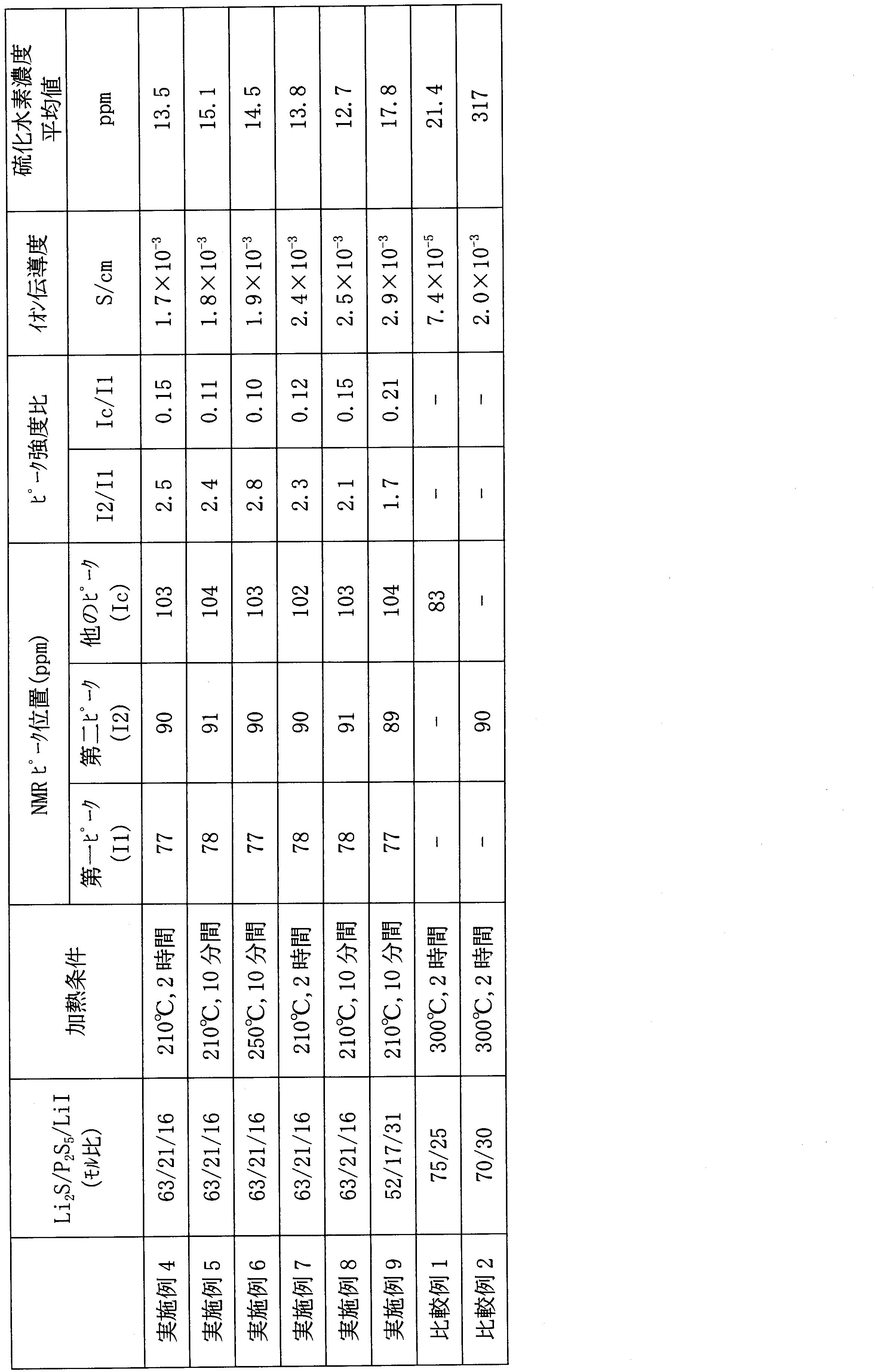
また、実施例1~9の硫化物系固体電解質は、いずれも、耐加水分解性に優れているため、従来よりも高い露点環境で使用できる可能性がある。このように、耐加水分解性に優れた硫化物系固体電解質は、これまで知られていない。比較例1の硫化物系固体電解質は、耐加水分解性に優れるが、イオン伝導度が低く、電池用途に適さない。
比較例2の硫化物系固体電解質は、高いイオン伝導度を示すが、耐加水分解性が悪く、作業環境を低露点に保つ必要がある。
(1)固体電解質(硫化物系ガラス:Li2S/P2S5/LiBr=64/21/14、MM法)の製造
製造例1で製造した硫化リチウムを用いて、国際公開公報WO07/066539の実施例1に準拠した方法で固体電解質(硫化物系ガラス)を製造した。
原料として、硫化リチウム0.333g(0.00725mol)、五硫化二リン(アルドリッチ社製)0.532g(0.00239mol)、臭化リチウム(アルドリッチ社製)0.140g(0.00161mol)をよく混合した。そして、この混合した粉末と直径10mmのジルコニア製ボール10ケと遊星型ボールミル(フリッチュ社製:型番P-7)アルミナ製ポットに投入し完全密閉するとともにこのアルミナ製ポット内にアルゴンを充填し、アルゴン雰囲気にした。
得られた固体電解質について、イオン伝導度(熱処理前)及びTG-DTA(熱重量測定装置)により結晶化温度(Tc)を測定した。結果を表4に示す。結晶化温度はメトラートレド社製TGA-DSC1を用いて測定した。
得られた硫化物系ガラス0.5gを、温度230℃に制御したオーブン内で、予め230℃に加熱された2枚のステンレス板の間にすばやく挟み、10分間放置することで硫化物系固体電解質を得た。加熱した金属板に挟むことにより、試料は約2分で230℃に達する。
得られた固体電解質のイオン伝導度(熱処理後)を評価した。結果を表4に示す。得られた試料の31P-NMR結果を図5に示す。第一ピークの位置(ショルダーピークとして現れた)は77.7ppm、第二ピーク位置は88.0ppm、他のピークの位置は107.7ppm、I2/I1は2.57、Ic/I1は0.27であった。
図7から分かるように、実施例10の固体電解質は、2θ=15.7,16.3,21.4,25.0,30.1,31.5,33.1degに回折ピークを有することが分かる。
(1)固体電解質(硫化物系ガラス:Li2S/P2S5=75/25):MM法)の製造
原料として硫化リチウム0.383g(0.00833mol)と五硫化二リン(アルドリッチ社製)を0.618g(0.00278mol)を用いた以外は実施例10と同様にして硫化物系ガラスを製造した。
得られた硫化物系ガラスについて、TG-DTAにより、結晶化温度(Tc)を測定した。結果を表4に示す。尚、得られた硫化物系ガラスのイオン伝導度は、1.3×10⁻⁴S/cmであった。
得られた硫化物系ガラスの粉末を、公開特許公報2005-228570Aに従い260℃まで10℃/minで昇温後、室温まで冷却することで硫化物系固体電解質を得た。
得られた固体電解質のイオン伝導度を評価した。結果を表4に示す。また、得られた固体電解質の粉末XRD回折パターンを図6に示す。
図6から分かるように、比較例3の固体電解質は、2θ=13.7,17.5,18.1,19.9,22.8,25.8,27.6,29.1,31.3degに回折ピークを有することが分かる。
(1)固体電解質(硫化物系ガラス:Li2S/P2S5/LiBr=64/21/14、MM法)の製造
実施例10と同様にして硫化物系ガラスを製造した。
得られた硫化物系ガラスについて、イオン伝導度σ、及びTG-DTAにより結晶化温度(Tc)を測定した。結果を表4に示す。
得られた硫化物系ガラス0.5gをSUS製容器に投入し、予め温度230℃に制御したオーブンにセットした。そのまま2時間放置後、空冷し、硫化物系固体電解質を製造した。尚、試料が所定温度に達するまでに数十分かかる。
得られた固体電解質のイオン伝導度σを評価した。結果を表4に示す。また、得られた固体電解質の粉末XRD回折パターンを図6に示す。
図6から分かるように、実施例11の固体電解質は、2θ=15.6,16.3,21.2,25.1,30.0,31.4,33.1degに回折ピークを有することが分かる。
(1)固体電解質(硫化物系ガラス:Li2S/P2S5/LiBr=64/21/14、MM法)の製造
原料として、比較例3で得られた硫化物系ガラス0.864g、臭化リチウム(アルドリッチ社製)0.140gを用いた以外は、実施例10と同様にして硫化物系ガラスを製造した。
得られた硫化物系ガラスについて、イオン伝導度σ、及びTG-DTAにより結晶化温度(Tc)を測定した。結果を表4に示す。
得られた硫化物系ガラスを実施例10と同様の加熱処理を実施して硫化物系固体電解質を製造した。
得られた固体電解質のイオン伝導度を評価した。結果を表4に示す。また、得られた固体電解質の粉末XRD回折パターンを図6に示す。
図6から分かるように、実施例12の固体電解質は、2θ=15.5,16.2,21.2,25.1,30.1(ショルダー部),31.5,33.1degに回折ピークを有することが分かる。
(1)電解質前駆体(硫化物系ガラス:Li2S/P2S5=70/30、MM法)の製造
硫化リチウムの量を0.325g(0.00707mol)、五硫化二リンの量を0.675g(0.00303mol)とした以外は実施例10と同様にして硫化物系ガラスを製造した。
得られた硫化物系ガラスについて、イオン伝導度σ、及びTG-DTAにより結晶化温度(Tc)を測定した。結果を表4に示す。
得られた硫化物系ガラスの粉末を、公開特許公報2005-228570Aに従い260℃まで10℃/minで昇温後、室温まで冷却することで硫化物系固体電解質を製造した。
得られた固体電解質のイオン伝導度を評価した。結果を表4に示す。また、得られた固体電解質の粉末XRD回折パターンを図6に示す。
図6から分かるように、比較例4の固体電解質は、2θ=17.8,18.2,19.8,21.8,23.8,25.9,29.5,30.0degに回折ピークを有することが分かる。
(1)固体電解質(硫化物系ガラス:Li2S/P2S5/LiBr=69/23/7.5、MM法)の製造
原料として、硫化リチウム0.358g(0.00779mol)、五硫化二リン(アルドリッチ社製)0.573g(0.00258mol)、臭化リチウム(アルドリッチ社製)0.073g(0.00084mol)を用いた以外は、実施例10と同様にして硫化物系ガラスを製造した。
得られた硫化物系ガラスについて、イオン伝導度σ、及びTG-DTAにより結晶化温度(Tc)を測定した。結果を表4に示す。
得られた硫化物系ガラスを、加熱温度を240℃とした他は実施例10と同様の加熱処理を実施して硫化物系固体電解質を製造した。
得られた固体電解質のイオン伝導度σを評価した。結果を表4に示す。また、得られた固体電解質の粉末XRD回折パターンを図7に示す。
図7から分かるように、実施例13の固体電解質は、2θ=15.6,16.3,21.2,25.1,30.1,31.5,33.1degに回折ピークを有することが分かる。
(1)固体電解質(硫化物系ガラス:Li2S/P2S5/LiBr=58/19/23、MM法)の製造
原料として、硫化リチウム0.302g(0.00657mol)、五硫化二リン(アルドリッチ社製)0.482g(0.00217mol)、臭化リチウム(アルドリッチ社製)0.220g(0.00253mol)を用いた以外は、実施例10と同様にして硫化物系ガラスを製造した。
得られた硫化物系ガラスについて、イオン伝導度、及びTG-DTAにより結晶化温度(Tc)を測定した。結果を表4に示す。
得られた硫化物系ガラスを、加熱温度を220℃とした他は実施例10と同様の加熱処理を実施して硫化物系固体電解質を製造した。
得られた固体電解質のイオン伝導度σを評価した。結果を表4に示す。また、得られた固体電解質の粉末XRD回折パターンを図7に示す。
図7から分かるように、実施例14の固体電解質は、2θ=15.6,16.3,21.2,25.0,29.9,31.4,33.0degに回折ピークを有することが分かる。
(1)固体電解質(硫化物系ガラス:Li2S/P2S5/LiBr=52/17/31、MM法)の製造
原料として、硫化リチウム0.270g(0.00588mol)、五硫化二リン(アルドリッチ社製)0.431g(0.00194mol)、臭化リチウム(アルドリッチ社製)0.302g(0.00348mol)を用いた以外は、実施例10と同様にして硫化物系ガラスを製造した。
得られた硫化物系ガラスについて、イオン伝導度σ、及びTG-DTAにより結晶化温度(Tc)を測定した。結果を表4に示す。
得られた硫化物系ガラスを、加熱温度を200℃とした他は実施例10と同様の加熱処理を実施して硫化物系固体電解質を製造した。
得られた固体電解質のイオン伝導度σを評価した。結果を表4に示す。また、得られた固体電解質の粉末XRD回折パターンを図7に示す。
図7から分かるように、実施例15の固体電解質は、2θ=15.5,16.3,21.2,25.0,30.1,31.4,32.9degに回折ピークを有することが分かる。
実施例10及び13並びに比較例3及び4について前述の方法で硫化水素濃度平均値を評価した。結果を表5に示す。


一方、比較例3の硫化物系固体電解質は、耐加水分解性に優れるが、イオン伝導度が低く、電池用途に適さず、比較例4の硫化物系固体電解質は、高いイオン伝導度を示すが、耐加水分解性が悪く、作業環境を低露点に保つ必要がある。
(1)固体電解質(硫化物系ガラス:Li2S/P2S5/LiCl=64/21/14、MM法)の製造
原料として、硫化リチウム0.359g(0.00773mol)、五硫化二リン(アルドリッチ社製)0.574g(0.00258mol)、塩化リチウム(アルドリッチ社製)0.072g(0.00175mol)を用いた以外は、実施例10と同様にして硫化物系ガラスを製造した。
得られた硫化物系ガラスについて、TG-DTAにより結晶化温度(Tc)を測定した。結果を表6に示す。
得られた硫化物系ガラスを実施例10と同様の加熱処理を実施して硫化物系固体電解質を製造した。
得られた固体電解質のイオン伝導度σを評価した。結果を表6に示す。また、得られた固体電解質の粉末XRD回折パターンを図8に示す。尚、比較のため、実施例13のXRD回折パターンも示した。
実施例16の固体電解質は、2θ=15.6,16.3,17.9,20.3,21.4,26.0,29.8,31.7,33.2degに回折ピークを有することが分かる。
実施例16について前述の方法で硫化水素濃度平均値を評価した。結果は7.4ppmであった。
(1)固体電解質(硫化物系ガラス:Li2S/P2S5/LiCl=69/23/7.5、MM法)の製造
原料として、硫化リチウム0.373g(0.00804mol)、五硫化二リン(アルドリッチ社製)0.596g(0.00268mol)、塩化リチウム(アルドリッチ社製)0.036g(0.00086mol)を用いた以外は、実施例10と同様にして硫化物系ガラスを製造した。
得られた硫化物系ガラスについて、TG-DTAにより結晶化温度(Tc)を測定した。結果を表6に示す。
得られた硫化物系ガラスを、加熱温度を230℃とした他は実施例10と同様の加熱処理を実施して硫化物系固体電解質を製造した。
得られた固体電解質のイオン伝導度を評価した。結果を表6に示す。また、得られた固体電解質の粉末XRD回折パターンを図9に示す。
図9から分かるように、実施例17の固体電解質は、2θ=15.9,16.4,17.6,20.1,21.4,26.0,29.9,31.8,33.0degに回折ピークを有することが分かる。
(1)固体電解質(硫化物系ガラス:Li2S/P2S5/LiCl=58/19/23、MM法)の製造
原料として、硫化リチウム0.341g(0.00735mol)、五硫化二リン(アルドリッチ社製)0.546g(0.00245mol)、塩化リチウム(アルドリッチ社製)0.119g(0.00286mol)を用いた以外は、実施例10と同様にして硫化物系ガラスを製造した。
得られた硫化物系ガラスについて、TG-DTAにより結晶化温度(Tc)を測定した。結果を表6に示す。
得られた硫化物系ガラスを、加熱温度を230度とした他は実施例10と同様の加熱処理を実施して硫化物系固体電解質を製造した。
得られた固体電解質のイオン伝導度を評価した。結果を表6に示す。また、得られた固体電解質の粉末XRD回折パターンを図9に示す。
図9から分かるように、実施例18の固体電解質は、2θ=15.9,16.3,17.7,20.2,21.4,26.1,29.9,31.6,33.1degに回折ピークを有することが分かる。
(1)固体電解質(硫化物系ガラス:Li2S/P2S5/LiCl=52/17/31、MM法)の製造
原料として、硫化リチウム0.321g(0.00691mol)、五硫化二リン(アルドリッチ社製)0.513g(0.00230mol)、臭化リチウム(アルドリッチ社製)0.171g(0.00413mol)を用いた以外は、実施例10と同様にして硫化物系ガラスを製造した。
得られた硫化物系ガラスについて、TG-DTAにより結晶化温度(Tc)を測定した。結果を表6に示す。
得られた硫化物系ガラスを、加熱温度を230度とした他は実施例10と同様の加熱処理を実施して硫化物系固体電解質を製造した。
得られた固体電解質のイオン伝導度σを評価した。結果を表6に示す。また、得られた固体電解質の粉末XRD回折パターンを図9に示す。
図9から分かるように、実施例19の固体電解質は、2θ=15.8,16.3,17.8,21.4,30.0,31.7,33.0degに回折ピークを有することが分かる。

(1)固体電解質(硫化物系ガラス:Li2S/P2S5/PBr3=76/19/5、MM法)の製造
アルゴン雰囲気下において、製造例1で製造した硫化リチウム0.388g(0.00844mol)と五硫化二リン(アルドリッチ社製)0.471g(0.00212mol)を、Li2S/P2S5=80/20(mol/mol)となるように混合し、さらに三臭化リン0.160g(0.00058mol)を滴下し、よく混合した。そして、この混合した粉末と直径10mmのアルミナ製ボール10コと遊星型ボールミル(フリッチュ社製:型番P-7)をアルミナ製ポットに投入しアルゴン雰囲気のまま完全密閉した。
得られた硫化物系ガラス0.5gを、温度240℃に制御したオーブン内で、予め240℃に加熱された2枚のステンレス板の間にすばやく挟み、10分間放置することで硫化物系固体電解質を得た。加熱した金属板に挟むことにより、試料は約2分で240℃に達する。
得られた固体電解質のイオン伝導度σを評価したところ8x10⁻⁴S/cmであった。
得られた試料の31P-NMR測定では、第一ピークの位置(ショルダーピークとして現れた)は78.3ppm、第二ピーク位置は88.0ppm、他のピークの位置は107.9ppm、I2/I1は2.40、Ic/I1は0.42であった。
図10から分かるように、実施例20の固体電解質は、2θ=15.4,16.2,20.1,21.2,23.6,26.9,29.4,31.3,32.6degに回折ピークを有することが分かる(代表ピークを記載)。また、この化合物の組成はLi3.56PS3.95Br0.36である。
前述の方法で硫化水素濃度平均値を評価した。硫化水素平均発生濃度は38.3ppmであり比較例3と同等であり比較的少ない発生量であった。
この明細書に記載の文献及び本願のパリ優先の基礎となる日本出願明細書の内容を全てここに援用する。
Claims (34)
- 構成成分として、アルカリ金属元素、リン、硫黄及びハロゲンを含む固体電解質。
- 前記アルカリ金属元素がリチウムである請求項1に記載の固体電解質。
- 31P-NMRスペクトルにおいて、75.0ppm以上80.0ppm以下であるピーク領域にピークを有する請求項1又は2に記載の固体電解質。
- 31P-NMRスペクトルにおいて、86.0ppm以上92.0ppm以下であるピーク領域にピークを有する請求項1~3のいずれかに記載の固体電解質。
- 31P-NMRスペクトルにおいて、75.0ppm以上80.0ppm以下である第一ピーク領域に第一ピークを有し、
前記第一ピーク領域、及び86.0ppm以上92.0ppm以下の領域である第二ピーク領域以外の領域にあるピークの強度比が、前記第一ピークに対し0.5以下である請求項1~4のいずれかに記載の固体電解質。 - 前記第一ピーク領域及び第二ピーク領域に、それぞれピークを有する請求項5に記載の固体電解質。
- 前記第一ピーク(I1)に対する、前記第二ピーク領域にある第二ピーク(I2)のピーク強度比(I2/I1)が1~10である請求項6に記載の固体電解質。
- 下記式(A’)に示す組成を有する請求項1~7のいずれかに記載の固体電解質。
LaMbPcSdXe…(A’)
(式中、Lはアルカリ金属を示し、MはB,Al,Si,Ge,As,Se,Sn,Sb,Te,PbもしくはBi、又はこれらの組合せを示し、XはI,Cl,BrもしくはF又はこれらの組合せを示す。a~eは、0<a≦12、0≦b≦0.2、c=1,0<d≦9、0<e≦9を満たす。) - 前記bが0である請求項8に記載の固体電解質。
- 前記dが4である請求項8に記載の固体電解質。
- 前記Xが、I、Br又はClである請求項8~10のいずれかに記載の固体電解質。
- 結晶構造を有する請求項8~11のいずれかに記載の固体電解質。
- 前記Xが、Br又はClであり、非晶質である請求項8~10のいずれかに記載の固体電解質。
- 硫化リチウムと硫化リン、硫黄とリン、硫化リンと硫黄、又は硫化リンと硫黄とリンと、
下記式(E’)で表される化合物と、
を原料とする請求項8~13のいずれかに記載の固体電解質。
MwXx…(E’)
(式中、MはLi,B,Al,Si,P,S,Ge,As,Se,Sn,Sb,Te,Pb又はBiを示し、XはF,Cl,Br又はIを示す。wは1~2の整数を示し、xは1~10の整数を示す。) - 前記MがPであり、前記XがBr、I又はClである請求項14に記載の固体電解質。
- 前記MがLiであり、前記XがBr、I又はClである請求項14に記載の固体電解質。
- 非晶質であり、示差熱-熱重量測定において、結晶化ピークを2つ有する請求項8~11、13~16のいずれかに記載の固体電解質。
- 前記2つの結晶化ピークが150℃以上360℃以下の範囲にある請求項17に記載の固体電解質。
- 前記2つの結晶化ピーク間の幅が20~100℃である請求項17又は18に記載の固体電解質。
- 非晶質である請求項8~11、13~19のいずれかに記載の固体電解質を150℃以上360℃以下で加熱することにより得られる固体電解質。
- 請求項17~19のいずれかに記載の固体電解質を、前記2つの結晶化ピークで示される温度の間の温度で加熱して得られる固体電解質。
- 構成成分としてアルカリ金属元素を含み、
粉末X線回折(CuKα:λ=1.5418Å)において、少なくとも2θ=16.3±0.3deg,21.3±0.3deg,33.1±0.8degに回折ピークを有する固体電解質。 - 構成成分としてアルカリ金属元素を含み、
粉末X線回折(CuKα:λ=1.5418Å)において、少なくとも2θ=16.3±0.3deg,21.3±0.3deg,33.1±0.5degに回折ピークを有する固体電解質。 - 構成成分としてアルカリ金属元素を含み、
粉末X線回折(CuKα:λ=1.5418Å)において、2θ=15.6±0.3deg,16.3±0.3deg,21.3±0.3deg,30.1±0.5deg,31.5±0.3deg,33.1±0.3degに回折ピークを有する固体電解質。 - 構成成分としてアルカリ金属元素を含み、
粉末X線回折(CuKα:λ=1.5418Å)において、2θ=15.6±0.3deg,16.3±0.3deg,21.3±0.3deg,30.1±0.3deg,31.5±0.3deg,33.1±0.3degに回折ピークを有する固体電解質。 - 構成成分としてアルカリ金属元素を含み、
粉末X線回折(CuKα:λ=1.5418Å)において、2θ=15.6±0.3deg,16.3±0.3deg,21.3±0.3deg,29.8±0.3deg,31.5±0.3deg,33.1±0.3degに回折ピークを有する固体電解質。 - 構成成分としてアルカリ金属元素を含み、
粉末X線回折(CuKα:λ=1.5418Å)において、2θ=15.6±0.3deg,16.3±0.3deg,21.3±0.3deg,31.5±0.3deg,32.6±0.3degに回折ピークを有する固体電解質。 - 前記アルカリ金属元素が、リチウムである請求項22~27のいずれかに記載の固体電解質。
- イオン伝導度が5×10⁻⁴S/cm以上である請求項1~7及び22~28のいずれかに記載の固体電解質。
- 加水分解試験による硫化水素濃度平均値が200ppm以下である請求項1~7及び22~29のいずれかに記載の固体電解質。
- 構成成分として硫黄元素、リン元素及びハロゲン元素から選択される元素を1以上含む請求項22~30のいずれかに記載の固体電解質。
- 構成成分としてハロゲン元素を20モル%以下含む請求項22~31のいずれかに記載の固体電解質。
- 請求項1~32のいずれかに記載の固体電解質を含む電解質層。
- 正極層、電解質層及び負極層の少なくとも一つが、請求項1~32のいずれかに記載の固体電解質を含む電池。
Priority Applications (8)
| Application Number | Priority Date | Filing Date | Title |
|---|---|---|---|
| US14/355,715 US9620811B2 (en) | 2011-11-07 | 2012-11-02 | Solid electrolyte |
| AU2012333924A AU2012333924A1 (en) | 2011-11-07 | 2012-11-02 | Solid electrolyte |
| KR1020147011569A KR101973827B1 (ko) | 2011-11-07 | 2012-11-02 | 고체 전해질 |
| CA2854596A CA2854596C (en) | 2011-11-07 | 2012-11-02 | Solid electrolyte comprising lithium, phosphorus, sulfur, and bromine |
| CN201280054657.5A CN104025363B (zh) | 2011-11-07 | 2012-11-02 | 固体电解质 |
| EP12846932.7A EP2779298B1 (en) | 2011-11-07 | 2012-11-02 | Solid electrolyte |
| EP18158213.1A EP3361545B1 (en) | 2011-11-07 | 2012-11-02 | Solid electrolyte |
| US15/442,800 US9806373B2 (en) | 2011-11-07 | 2017-02-27 | Solid electrolyte |
Applications Claiming Priority (8)
| Application Number | Priority Date | Filing Date | Title |
|---|---|---|---|
| JP2011-243459 | 2011-11-07 | ||
| JP2011243459 | 2011-11-07 | ||
| JP2012-002228 | 2012-01-10 | ||
| JP2012002228 | 2012-01-10 | ||
| JP2012034890 | 2012-02-21 | ||
| JP2012-034890 | 2012-02-21 | ||
| JP2012147050A JP6234665B2 (ja) | 2011-11-07 | 2012-06-29 | 固体電解質 |
| JP2012-147050 | 2012-06-29 |
Related Child Applications (2)
| Application Number | Title | Priority Date | Filing Date |
|---|---|---|---|
| US14/355,715 A-371-Of-International US9620811B2 (en) | 2011-11-07 | 2012-11-02 | Solid electrolyte |
| US15/442,800 Continuation US9806373B2 (en) | 2011-11-07 | 2017-02-27 | Solid electrolyte |
Publications (1)
| Publication Number | Publication Date |
|---|---|
| WO2013069243A1 true WO2013069243A1 (ja) | 2013-05-16 |
Family
ID=48289338
Family Applications (1)
| Application Number | Title | Priority Date | Filing Date |
|---|---|---|---|
| PCT/JP2012/007053 Ceased WO2013069243A1 (ja) | 2011-11-07 | 2012-11-02 | 固体電解質 |
Country Status (9)
| Country | Link |
|---|---|
| US (2) | US9620811B2 (ja) |
| EP (2) | EP2779298B1 (ja) |
| JP (1) | JP6234665B2 (ja) |
| KR (1) | KR101973827B1 (ja) |
| CN (1) | CN104025363B (ja) |
| AU (1) | AU2012333924A1 (ja) |
| CA (1) | CA2854596C (ja) |
| TW (1) | TWI586021B (ja) |
| WO (1) | WO2013069243A1 (ja) |
Cited By (23)
| Publication number | Priority date | Publication date | Assignee | Title |
|---|---|---|---|---|
| WO2014002483A1 (ja) * | 2012-06-29 | 2014-01-03 | 出光興産株式会社 | 正極合材 |
| WO2014073197A1 (ja) * | 2012-11-06 | 2014-05-15 | 出光興産株式会社 | 固体電解質 |
| JP2014093262A (ja) * | 2012-11-06 | 2014-05-19 | Idemitsu Kosan Co Ltd | 固体電解質 |
| JP2014093261A (ja) * | 2012-11-06 | 2014-05-19 | Idemitsu Kosan Co Ltd | 固体電解質 |
| WO2015001818A1 (ja) * | 2013-07-04 | 2015-01-08 | 三井金属鉱業株式会社 | 結晶性固体電解質及びその製造方法 |
| JP2015005372A (ja) * | 2013-06-19 | 2015-01-08 | 出光興産株式会社 | 硫化物系固体電解質の製造方法 |
| JP2015032462A (ja) * | 2013-08-02 | 2015-02-16 | トヨタ自動車株式会社 | 硫化物固体電解質材料 |
| JP2015041572A (ja) * | 2013-08-23 | 2015-03-02 | 株式会社豊田中央研究所 | 無機マグネシウム固体電解質、マグネシウム電池、電気化学デバイス及び無機マグネシウム固体電解質の製造方法 |
| JP2015088226A (ja) * | 2013-10-28 | 2015-05-07 | トヨタ自動車株式会社 | 硫化物固体電解質の製造方法 |
| CN104810547A (zh) * | 2014-01-24 | 2015-07-29 | 丰田自动车株式会社 | 硫化物固体电解质的制造方法 |
| US20150333367A1 (en) * | 2014-05-15 | 2015-11-19 | Toyota Jidosha Kabushiki Kaisha | Sulfide solid electrolyte material, battery, and method for producing sulfide solid electrolyte material |
| US20150333368A1 (en) * | 2014-05-15 | 2015-11-19 | Toyota Jidosha Kabushiki Kaisha | Sulfide solid electrolyte material, battery, and method for producing sulfide solid electrolyte material |
| WO2016009768A1 (ja) * | 2014-07-16 | 2016-01-21 | 三井金属鉱業株式会社 | リチウムイオン電池用硫化物系固体電解質 |
| WO2017022464A1 (ja) * | 2015-07-31 | 2017-02-09 | 国立大学法人東京工業大学 | α-リチウム固体電解質 |
| JPWO2014192309A1 (ja) * | 2013-05-31 | 2017-02-23 | 出光興産株式会社 | 固体電解質の製造方法 |
| JP2017117635A (ja) * | 2015-12-24 | 2017-06-29 | 出光興産株式会社 | 硫化物固体電解質、硫化物ガラス、電極合材及びリチウムイオン電池 |
| WO2018139629A1 (ja) * | 2017-01-30 | 2018-08-02 | 三菱瓦斯化学株式会社 | イオン伝導体及びその製造方法 |
| US10461363B2 (en) | 2014-06-25 | 2019-10-29 | Tokyo Institute Of Technology | Sulfide solid electrolyte material, battery, and producing method for sulfide solid electrolyte material |
| US11127974B2 (en) | 2018-05-14 | 2021-09-21 | Samsung Electronics Co., Ltd. | Method of preparing sulfide-based solid electrolyte, sulfide-based solid electrolyte prepared therefrom, and solid secondary battery including the sulfide electrolyte |
| WO2021193192A1 (ja) * | 2020-03-23 | 2021-09-30 | 三井金属鉱業株式会社 | 硫化物固体電解質、及びそれを用いた電極合剤、固体電解質層並びに電池 |
| US11245131B2 (en) | 2015-12-25 | 2022-02-08 | Samsung Electronics Co., Ltd. | Solid electrolyte and lithium battery including the same |
| US11637312B2 (en) | 2017-06-29 | 2023-04-25 | Idemitsu Kosan Co., Ltd. | Sulfide solid electrolyte |
| US11799126B2 (en) | 2019-05-31 | 2023-10-24 | Samsung Electronics Co., Ltd. | Method of preparing solid electrolyte and all-solid battery including solid electrolyte prepared by the method |
Families Citing this family (92)
| Publication number | Priority date | Publication date | Assignee | Title |
|---|---|---|---|---|
| EP2997611B1 (en) | 2013-05-15 | 2026-04-22 | QuantumScape Battery, Inc. | Solid state catholyte or electrolyte for battery |
| JP6310713B2 (ja) * | 2014-02-03 | 2018-04-11 | 古河機械金属株式会社 | 固体電解質材料、リチウムイオン電池および固体電解質材料の製造方法 |
| JP5975071B2 (ja) * | 2014-07-22 | 2016-08-23 | トヨタ自動車株式会社 | 硫化物固体電解質材料、電池および硫化物固体電解質材料の製造方法 |
| EP3214054A4 (en) * | 2014-10-31 | 2018-07-18 | Idemitsu Kosan Co., Ltd | Sulfide glass and crystalline solid electrolyte production method, crystalline solid electrolyte, sulfide glass and solid-state battery |
| EP3240089B1 (en) | 2014-12-26 | 2019-04-24 | Mitsui Mining and Smelting Co., Ltd. | Sulfide-based solid electrolyte for lithium ion cell, and solid electrolyte compound |
| WO2016132872A1 (ja) * | 2015-02-20 | 2016-08-25 | 富士フイルム株式会社 | 固体電解質組成物、これを用いた電池用電極シートおよび全固体二次電池、ならびに電池用電極シートおよび全固体二次電池の製造方法 |
| JP6577222B2 (ja) | 2015-04-17 | 2019-09-18 | トヨタ自動車株式会社 | 硫化物固体電解質の製造方法及び硫黄系材料 |
| KR101684130B1 (ko) * | 2015-06-16 | 2016-12-07 | 현대자동차주식회사 | 리튬 이온 전도성 황화물의 제조방법, 이에 의하여 제조된 리튬 이온 전도성 황화물, 및 이를 포함하는 고체전해질, 전고체 배터리 |
| WO2016210371A1 (en) * | 2015-06-24 | 2016-12-29 | Quantumscape Corporation | Composite electrolytes |
| JP6380263B2 (ja) | 2015-06-29 | 2018-08-29 | トヨタ自動車株式会社 | 硫化物固体電解質の製造方法 |
| JP2017045613A (ja) * | 2015-08-26 | 2017-03-02 | 出光興産株式会社 | 硫化物固体電解質及びその製造方法 |
| JP2017091810A (ja) * | 2015-11-10 | 2017-05-25 | トヨタ自動車株式会社 | 正極合材の製造方法 |
| CN117558971A (zh) | 2015-11-24 | 2024-02-13 | 锡安能量公司 | 离子传导化合物及其相关用途 |
| JP6320983B2 (ja) * | 2015-12-01 | 2018-05-09 | 出光興産株式会社 | 硫化物ガラスセラミックスの製造方法 |
| KR102765039B1 (ko) * | 2015-12-04 | 2025-02-11 | 퀀텀스케이프 배터리, 인코포레이티드 | 리튬, 인, 황 및 요오드를 포함하는 전해질 및 음극액 조성물, 전기화학적 장치를 위한 전해질 막, 및 이들 전해질 및 음극액을 제조하는 어닐링 방법(annealing method). |
| CN108370060B (zh) | 2015-12-15 | 2023-06-30 | 新罗纳米技术有限公司 | 用于安全金属和金属离子电池的固态电解质 |
| CN108780683B (zh) | 2016-03-14 | 2021-02-12 | 出光兴产株式会社 | 固体电解质和固体电解质的制造方法 |
| WO2017159665A1 (ja) | 2016-03-14 | 2017-09-21 | 出光興産株式会社 | ハロゲン化アルカリ金属の製造方法、及び硫化物系固体電解質の製造方法 |
| KR101842556B1 (ko) * | 2016-03-30 | 2018-05-14 | 울산과학기술원 | 고체 전해질, 이의 제조방법, 및 이를 포함하는 전고체 전지 |
| US11342630B2 (en) | 2016-08-29 | 2022-05-24 | Quantumscape Battery, Inc. | Catholytes for solid state rechargeable batteries, battery architectures suitable for use with these catholytes, and methods of making and using the same |
| JP6679736B2 (ja) | 2016-09-12 | 2020-04-15 | 出光興産株式会社 | 硫化物固体電解質 |
| KR102428981B1 (ko) * | 2016-11-16 | 2022-08-03 | 이데미쓰 고산 가부시키가이샤 | 황화물 고체 전해질 |
| KR102417513B1 (ko) | 2016-11-22 | 2022-07-05 | 현대자동차주식회사 | 광범위한 결정화 온도 범위에서 고이온전도도를 갖는 황화물계 고체전해질 및 이의 제조방법 |
| WO2018096957A1 (ja) * | 2016-11-28 | 2018-05-31 | 国立研究開発法人産業技術総合研究所 | 無機硫化物及びその製造方法 |
| US11502331B2 (en) | 2016-12-14 | 2022-11-15 | Idemitsu Kosan Co., Ltd. | Method for producing sulfide solid electrolyte |
| KR101867555B1 (ko) * | 2017-01-04 | 2018-06-14 | 울산과학기술원 | 전극 활물질-고체 전해질 복합체, 이의 제조 방법, 이를 포함하는 전고체 전지 |
| JP6763808B2 (ja) | 2017-03-14 | 2020-09-30 | 出光興産株式会社 | 固体電解質の製造方法 |
| CN106972195A (zh) * | 2017-04-17 | 2017-07-21 | 哈尔滨工业大学无锡新材料研究院 | 一种无机硫化物电解质及其制备方法 |
| DE112018002679T5 (de) * | 2017-05-24 | 2020-03-05 | Idemitsu Kosan Co., Ltd. | Sulfid-festelektrolyt |
| KR102833170B1 (ko) | 2017-05-24 | 2025-07-10 | 시온 파워 코퍼레이션 | 이온 전도성 화합물 및 관련 용도 |
| JP7369988B2 (ja) * | 2017-06-14 | 2023-10-27 | パナソニックIpマネジメント株式会社 | 硫化物固体電解質材料を用いた電池 |
| JP7236648B2 (ja) * | 2017-09-08 | 2023-03-10 | パナソニックIpマネジメント株式会社 | 硫化物固体電解質材料及びそれを用いた電池 |
| CN109786814B (zh) | 2017-11-14 | 2025-01-03 | 三星电子株式会社 | 用于全固态二次电池的固体电解质、复合电极、全固态二次电池和制备固体电解质的方法 |
| CN114976221A (zh) | 2017-11-14 | 2022-08-30 | 出光兴产株式会社 | 含金属元素的硫化物类固体电解质及其制造方法 |
| US10985407B2 (en) | 2017-11-21 | 2021-04-20 | Samsung Electronics Co., Ltd. | All-solid-state secondary battery including anode active material alloyable with lithium and method of charging the same |
| CN109818050B (zh) * | 2017-11-22 | 2021-04-09 | 中国科学院物理研究所 | Nasicon结构钠离子固体电解质/卤化钠复合材料及其制备方法和应用 |
| KR20190066792A (ko) * | 2017-12-06 | 2019-06-14 | 현대자동차주식회사 | 아지로다이트형 결정구조를 갖는 전고체 전지용 황화물계 고체 전해질의 제조 방법 |
| CN109935900B (zh) * | 2017-12-19 | 2021-10-19 | 成都大超科技有限公司 | 固态电解质及其锂电池、锂电池电芯及其制备方法 |
| US11437643B2 (en) | 2018-02-20 | 2022-09-06 | Samsung Electronics Co., Ltd. | All-solid-state secondary battery |
| US11688879B2 (en) * | 2018-03-12 | 2023-06-27 | Mitsui Mining & Smelting Co., Ltd. | Sulfide-based solid electrolyte particles |
| JP6595031B2 (ja) * | 2018-03-19 | 2019-10-23 | 古河機械金属株式会社 | 固体電解質材料、リチウムイオン電池および固体電解質材料の製造方法 |
| CN108598475B (zh) * | 2018-04-25 | 2021-03-26 | 广东工业大学 | 离子电池用成分结构可调控的磷硫硒系列负极材料 |
| JP2019200851A (ja) * | 2018-05-14 | 2019-11-21 | トヨタ自動車株式会社 | 固体電解質、全固体電池および固体電解質の製造方法 |
| JP7077766B2 (ja) * | 2018-05-18 | 2022-05-31 | トヨタ自動車株式会社 | 硫化物系固体電解質、当該硫化物系固体電解質の製造方法、及び、全固体電池の製造方法 |
| CN112074918B (zh) * | 2018-06-13 | 2022-02-22 | 三菱瓦斯化学株式会社 | Lgps类固体电解质和制造方法 |
| US12107214B2 (en) * | 2018-06-15 | 2024-10-01 | Georgia Tech Research Corporation | Solid electrolyte materials and methods of making the same |
| KR102063159B1 (ko) * | 2018-07-17 | 2020-01-08 | 한국과학기술연구원 | 셀레늄을 포함하는 리튬 이온 전도성 황화물계 고체전해질 및 이의 제조방법 |
| KR102728661B1 (ko) | 2018-09-06 | 2024-11-11 | 삼성전자주식회사 | 고체 전해질, 그 제조방법 및 이를 포함하는 이차전지 |
| WO2020058529A1 (en) | 2018-09-21 | 2020-03-26 | Philipps-Universität Marburg | Amorphous solid li+ electrolyte, process for production of the amorphous solid electrolyte and usage of the amorphous solid electrolyte |
| JP7119902B2 (ja) * | 2018-10-29 | 2022-08-17 | トヨタ自動車株式会社 | 硫化物系固体電解質 |
| KR20200053099A (ko) * | 2018-11-08 | 2020-05-18 | 현대자동차주식회사 | 습식법으로 합성된 황화물계 고체전해질, 이의 제조용 조성물 및 이의 제조방법 |
| WO2020095937A1 (ja) | 2018-11-08 | 2020-05-14 | 三井金属鉱業株式会社 | 硫黄含有化合物、固体電解質及び電池 |
| KR102650658B1 (ko) | 2018-11-15 | 2024-03-25 | 삼성전자주식회사 | 헤테로고리 방향족 구조의 음이온을 포함하는 금속염 및 그 제조방법, 그리고 상기 금속염을 포함하는 전해질 및 전기화학소자 |
| US11411246B2 (en) | 2018-12-06 | 2022-08-09 | Samsung Electronics Co., Ltd. | All-solid secondary battery and method of manufacturing all-solid secondary battery |
| CN109712823A (zh) * | 2018-12-27 | 2019-05-03 | 上海奥威科技开发有限公司 | 固态玻璃电解质及其复合电极材料、膜片、电极片和全固态超级电容器 |
| KR102831128B1 (ko) * | 2019-03-07 | 2025-07-04 | 삼성전자주식회사 | 황화물계 고체 전해질, 이를 포함하는 전고체 이차전지 및 황화물계 고체 전해질의 제조방법 |
| EP3716389B1 (en) * | 2019-03-28 | 2025-04-09 | Toyota Jidosha Kabushiki Kaisha | Sulfide solid electrolyte, precursor of sulfide solid electrolyte, all solid state battery and method for producing sulfide solid electrolyte |
| WO2020203045A1 (ja) | 2019-03-29 | 2020-10-08 | 古河機械金属株式会社 | 硫化物系無機固体電解質材料用の五硫化二リン組成物 |
| CN109970347A (zh) * | 2019-04-29 | 2019-07-05 | 齐鲁工业大学 | 一种提高锂离子电池性能的TeO2-V2O5-CuO微晶玻璃负极材料 |
| US11264602B2 (en) | 2019-05-08 | 2022-03-01 | Samsung Electronics Co., Ltd. | Sulfide glass-ceramic lithium-ion solid-state conductor |
| US11824155B2 (en) | 2019-05-21 | 2023-11-21 | Samsung Electronics Co., Ltd. | All-solid lithium secondary battery and method of charging the same |
| JP7151658B2 (ja) * | 2019-08-01 | 2022-10-12 | トヨタ自動車株式会社 | 正極合材 |
| US11702337B2 (en) | 2019-09-27 | 2023-07-18 | Samsung Sdi Co., Ltd. | Solid ion conductor, solid electrolyte including the solid ion conductor, electrochemical cell including the solid ion conductor, and preparation method of the same |
| KR102292161B1 (ko) * | 2019-10-22 | 2021-08-24 | 한국과학기술연구원 | 다중 칼코겐 원소가 도입된 황화물계 리튬-아지로다이트 이온 초전도체 및 이의 제조방법 |
| CN110808407B (zh) * | 2019-11-01 | 2020-11-20 | 宁德新能源科技有限公司 | 一种不含磷的硫化物固态电解质 |
| JP7143834B2 (ja) * | 2019-11-14 | 2022-09-29 | トヨタ自動車株式会社 | 電極の製造方法、電極、および全固体電池 |
| EP4075450B1 (en) * | 2019-12-11 | 2026-02-04 | Mitsui Kinzoku Company, Limited | Sulfide solid electrolyte |
| WO2021132538A1 (ja) * | 2019-12-27 | 2021-07-01 | 三井金属鉱業株式会社 | 硫化物固体電解質及びその製造方法 |
| US20230026839A1 (en) * | 2019-12-27 | 2023-01-26 | Showa Denko K.K. | Lithium ion-conductive oxide and use for same |
| KR102895752B1 (ko) * | 2020-02-07 | 2025-12-03 | 삼성에스디아이 주식회사 | 고체이온전도체 화합물, 이를 포함하는 고체전해질, 이를 포함하는 전기화학 셀, 및 이의 제조방법 |
| TWI829867B (zh) * | 2020-02-19 | 2024-01-21 | 日商三井金屬鑛業股份有限公司 | 含硫化合物、固體電解質及電池 |
| WO2021172159A1 (ja) * | 2020-02-28 | 2021-09-02 | 株式会社Gsユアサ | 固体電解質、固体電解質の製造方法及び蓄電素子 |
| WO2021188535A1 (en) * | 2020-03-16 | 2021-09-23 | Solid Power, Inc. | Solid electrolyte material and solid-state battery made therewith |
| JP7692734B2 (ja) * | 2020-05-27 | 2025-06-16 | 出光興産株式会社 | 固体電解質の製造方法 |
| CN115667146B (zh) | 2020-05-27 | 2025-09-23 | 出光兴产株式会社 | 卤化锂化合物的制造方法 |
| EP4180390A4 (en) | 2020-07-07 | 2024-08-21 | Agc Inc. | SULFIDE-BASED SOLID ELECTROLYTE USED FOR LITHIUM-ION SECONDARY BATTERY AND PRODUCTION METHOD THEREOF, SOLID ELECTROLYTE LAYER AND LITHIUM-ION SECONDARY BATTERY |
| CN115734942B (zh) * | 2020-07-09 | 2024-12-31 | 三井金属矿业株式会社 | 硫化锂的制造方法 |
| JP7563033B2 (ja) * | 2020-08-06 | 2024-10-08 | 株式会社Gsユアサ | 硫化物固体電解質、蓄電素子及び硫化物固体電解質の製造方法 |
| KR20220039386A (ko) * | 2020-09-22 | 2022-03-29 | 삼성에스디아이 주식회사 | 고체이온전도체 화합물, 이를 포함하는 고체전해질, 이를 포함하는 전기화학 셀, 및 이의 제조방법 |
| JP2022059592A (ja) * | 2020-10-01 | 2022-04-13 | 国立大学法人東京工業大学 | 全固体電池の充放電方法およびそれに用いることができる固体電解質材 |
| KR102406069B1 (ko) * | 2020-11-25 | 2022-06-13 | 한국과학기술연구원 | 할로겐의 완전 점유형 구조가 도입된 리튬-아지로다이트 기반 이온 초전도체 및 이의 제조방법 |
| CN114122508B (zh) * | 2021-11-26 | 2024-02-23 | 湖州昆仑先端固态电池科技有限公司 | 一种硫化物固体电解质及其制备方法和应用 |
| JP7751485B2 (ja) | 2021-12-27 | 2025-10-08 | 出光興産株式会社 | 硫化物固体電解質の製造方法及び電極合材の製造方法 |
| KR102773821B1 (ko) * | 2022-05-16 | 2025-02-27 | 울산대학교 산학협력단 | 황화물계 고체 전해질, 이를 포함하는 전고체 리튬 전지 및 이의 제조 방법 |
| US20240332611A1 (en) * | 2023-03-30 | 2024-10-03 | Rivian Ip Holdings, Llc | Sulfide-based composite solid state electrolytes and related methods |
| KR20250038875A (ko) * | 2023-09-12 | 2025-03-20 | 삼성에스디아이 주식회사 | 고체 이차전지용 양극 및 이를 포함하는 고체 이차전지 |
| CN121925399A (zh) | 2023-09-28 | 2026-04-24 | Agc株式会社 | 硫化物固体电解质 |
| WO2025069781A1 (ja) | 2023-09-28 | 2025-04-03 | Agc株式会社 | 硫化物固体電解質及びその製造方法 |
| US20250192225A1 (en) * | 2023-12-08 | 2025-06-12 | Solid Power Operating, Inc. | Solid electrolyte materials and methods for making the same |
| CN120824408A (zh) * | 2024-04-11 | 2025-10-21 | 宁德时代新能源科技股份有限公司 | 硫化物固体电解质及其制备方法、固体电解质膜、电极极片、固态电池和用电装置 |
| CN120824407A (zh) * | 2024-04-11 | 2025-10-21 | 宁德时代新能源科技股份有限公司 | 硫化物固体电解质及其制备方法、固体电解质膜、电极极片、固态电池和用电装置 |
| WO2025244481A1 (ko) * | 2024-05-24 | 2025-11-27 | 주식회사 솔리비스 | 황화물계 고체전해질의 제조방법 |
Citations (31)
| Publication number | Priority date | Publication date | Assignee | Title |
|---|---|---|---|---|
| JPH06279049A (ja) | 1993-03-26 | 1994-10-04 | Matsushita Electric Ind Co Ltd | 硫化物系リチウムイオン導電性固体電解質及びその合成法 |
| JPH07330312A (ja) | 1994-06-03 | 1995-12-19 | Idemitsu Petrochem Co Ltd | 硫化リチウムの製造方法 |
| JPH09283156A (ja) | 1996-04-16 | 1997-10-31 | Matsushita Electric Ind Co Ltd | リチウムイオン伝導性固体電解質およびその製造方法 |
| JPH10321256A (ja) * | 1997-05-19 | 1998-12-04 | Matsushita Electric Ind Co Ltd | 固体電解質あるいは電極の加工方法及びリチウム電池の製造方法 |
| JPH11134937A (ja) | 1997-10-31 | 1999-05-21 | Osaka Prefecture | イオン伝導性硫化物ガラスの製造方法、イオン伝導性硫化物ガラス、固体型電解質及び全固体型二次電池 |
| JP2003346896A (ja) * | 2002-05-30 | 2003-12-05 | Fujitsu Ltd | 固体電解質の製造方法、固体電解質、およびリチウム電池 |
| WO2004093099A1 (ja) | 2003-04-15 | 2004-10-28 | Idemitsu Kosan Co., Ltd. | リチウムイオン導電性固体電解質の製造方法及びそれを用いた全固体型二次電池 |
| JP2004348972A (ja) | 2003-04-24 | 2004-12-09 | Idemitsu Petrochem Co Ltd | リチウムイオン伝導性硫化物ガラス及びガラスセラミックスの製造方法並びに該ガラスセラミックスを用いた全固体型電池 |
| JP2004348973A (ja) | 2003-04-24 | 2004-12-09 | Idemitsu Petrochem Co Ltd | リチウムイオン伝導性硫化物ガラス及びガラスセラミックスの製造方法並びに該ガラスセラミックスを用いた全固体型電池 |
| WO2005040039A1 (ja) | 2003-10-23 | 2005-05-06 | Idemitsu Kosan Co., Ltd. | 硫化リチウムの精製方法 |
| JP2005228570A (ja) | 2004-02-12 | 2005-08-25 | Idemitsu Kosan Co Ltd | リチウムイオン伝導性硫化物系結晶化ガラス及びその製造方法 |
| WO2005104003A1 (en) | 2004-03-31 | 2005-11-03 | Exxonmobil Upstream Research Company | Method for constructing a geologic model of a subsurface reservoir |
| WO2005119706A1 (ja) | 2004-06-04 | 2005-12-15 | Idemitsu Kosan Co., Ltd. | 高性能全固体リチウム電池 |
| WO2007066539A1 (ja) | 2005-12-09 | 2007-06-14 | Idemitsu Kosan Co., Ltd. | リチウムイオン伝導性硫化物系固体電解質及びそれを用いた全固体リチウム電池 |
| WO2009047977A1 (ja) | 2007-10-11 | 2009-04-16 | Idemitsu Kosan Co., Ltd. | リチウムイオン伝導性固体電解質の製造方法 |
| JP2009110920A (ja) | 2007-10-11 | 2009-05-21 | Idemitsu Kosan Co Ltd | 硫化物系固体電解質の製造方法、全固体リチウム二次電池、全固体リチウム一次電池及びこれらを備えた装置 |
| JP2009211950A (ja) | 2008-03-04 | 2009-09-17 | Idemitsu Kosan Co Ltd | 固体電解質及びその製造方法 |
| JP2009238952A (ja) | 2008-03-26 | 2009-10-15 | Kyocera Corp | 支持用キャリア |
| JP2010030889A (ja) | 2008-07-01 | 2010-02-12 | Idemitsu Kosan Co Ltd | リチウムイオン伝導性硫化物ガラスの製造方法、リチウムイオン伝導性硫化物ガラスセラミックスの製造方法及び硫化物ガラス製造用のメカニカルミリング処理装置 |
| JP2010090003A (ja) | 2008-10-09 | 2010-04-22 | Idemitsu Kosan Co Ltd | 硫化物系固体電解質の製造方法 |
| JP2010140893A (ja) | 2008-11-17 | 2010-06-24 | Idemitsu Kosan Co Ltd | 固体電解質の製造装置及び製造方法 |
| JP2010163356A (ja) | 2008-12-15 | 2010-07-29 | Idemitsu Kosan Co Ltd | 硫化リチウムの製造方法 |
| JP2010186744A (ja) | 2009-01-15 | 2010-08-26 | Idemitsu Kosan Co Ltd | リチウムイオン伝導性固体電解質の製造方法 |
| JP2010199033A (ja) | 2009-02-27 | 2010-09-09 | Osaka Prefecture Univ | 硫化物固体電解質材料 |
| JP2010262860A (ja) | 2009-05-08 | 2010-11-18 | Panasonic Corp | リチウムイオン電池 |
| JP2010270191A (ja) | 2009-05-20 | 2010-12-02 | Tokuyama Corp | コーティング組成物および光学物品 |
| WO2011065401A1 (ja) * | 2009-11-26 | 2011-06-03 | 日本化学工業株式会社 | リチウム二次電池用活物質およびこれを用いたリチウム二次電池 |
| JP2011124081A (ja) * | 2009-12-10 | 2011-06-23 | Idemitsu Kosan Co Ltd | リチウムイオン伝導性硫化物ガラス及びそれを用いたリチウムイオン電池 |
| JP2012048971A (ja) * | 2010-08-26 | 2012-03-08 | Toyota Motor Corp | 硫化物固体電解質材料、正極体およびリチウム固体電池 |
| JP2012048973A (ja) * | 2010-08-26 | 2012-03-08 | Toyota Motor Corp | 硫化物固体電解質材料およびリチウム固体電池 |
| JP2012104279A (ja) * | 2010-11-08 | 2012-05-31 | Toyota Motor Corp | 硫化物固体電解質材料、リチウム固体電池、および硫化物固体電解質材料の製造方法 |
Family Cites Families (5)
| Publication number | Priority date | Publication date | Assignee | Title |
|---|---|---|---|---|
| JP3151925B2 (ja) * | 1992-05-07 | 2001-04-03 | 松下電器産業株式会社 | 非晶質リチウムイオン伝導性固体電解質並びにその合成法 |
| JP3343934B2 (ja) * | 1992-05-07 | 2002-11-11 | 松下電器産業株式会社 | 非晶質リチウムイオン伝導性固体電解質並びにその合成法 |
| DE102007048289A1 (de) | 2007-10-08 | 2009-04-09 | Universität Siegen | Lithium-Argyrodite |
| JP2011096630A (ja) * | 2009-10-02 | 2011-05-12 | Sanyo Electric Co Ltd | 固体リチウム二次電池及びその製造方法 |
| JP5443445B2 (ja) * | 2011-07-06 | 2014-03-19 | トヨタ自動車株式会社 | 硫化物固体電解質材料、リチウム固体電池、および、硫化物固体電解質材料の製造方法 |
-
2012
- 2012-06-29 JP JP2012147050A patent/JP6234665B2/ja active Active
- 2012-11-02 WO PCT/JP2012/007053 patent/WO2013069243A1/ja not_active Ceased
- 2012-11-02 US US14/355,715 patent/US9620811B2/en active Active
- 2012-11-02 KR KR1020147011569A patent/KR101973827B1/ko active Active
- 2012-11-02 AU AU2012333924A patent/AU2012333924A1/en not_active Abandoned
- 2012-11-02 EP EP12846932.7A patent/EP2779298B1/en active Active
- 2012-11-02 CA CA2854596A patent/CA2854596C/en active Active
- 2012-11-02 CN CN201280054657.5A patent/CN104025363B/zh active Active
- 2012-11-02 EP EP18158213.1A patent/EP3361545B1/en active Active
- 2012-11-07 TW TW101141356A patent/TWI586021B/zh active
-
2017
- 2017-02-27 US US15/442,800 patent/US9806373B2/en active Active
Patent Citations (31)
| Publication number | Priority date | Publication date | Assignee | Title |
|---|---|---|---|---|
| JPH06279049A (ja) | 1993-03-26 | 1994-10-04 | Matsushita Electric Ind Co Ltd | 硫化物系リチウムイオン導電性固体電解質及びその合成法 |
| JPH07330312A (ja) | 1994-06-03 | 1995-12-19 | Idemitsu Petrochem Co Ltd | 硫化リチウムの製造方法 |
| JPH09283156A (ja) | 1996-04-16 | 1997-10-31 | Matsushita Electric Ind Co Ltd | リチウムイオン伝導性固体電解質およびその製造方法 |
| JPH10321256A (ja) * | 1997-05-19 | 1998-12-04 | Matsushita Electric Ind Co Ltd | 固体電解質あるいは電極の加工方法及びリチウム電池の製造方法 |
| JPH11134937A (ja) | 1997-10-31 | 1999-05-21 | Osaka Prefecture | イオン伝導性硫化物ガラスの製造方法、イオン伝導性硫化物ガラス、固体型電解質及び全固体型二次電池 |
| JP2003346896A (ja) * | 2002-05-30 | 2003-12-05 | Fujitsu Ltd | 固体電解質の製造方法、固体電解質、およびリチウム電池 |
| WO2004093099A1 (ja) | 2003-04-15 | 2004-10-28 | Idemitsu Kosan Co., Ltd. | リチウムイオン導電性固体電解質の製造方法及びそれを用いた全固体型二次電池 |
| JP2004348972A (ja) | 2003-04-24 | 2004-12-09 | Idemitsu Petrochem Co Ltd | リチウムイオン伝導性硫化物ガラス及びガラスセラミックスの製造方法並びに該ガラスセラミックスを用いた全固体型電池 |
| JP2004348973A (ja) | 2003-04-24 | 2004-12-09 | Idemitsu Petrochem Co Ltd | リチウムイオン伝導性硫化物ガラス及びガラスセラミックスの製造方法並びに該ガラスセラミックスを用いた全固体型電池 |
| WO2005040039A1 (ja) | 2003-10-23 | 2005-05-06 | Idemitsu Kosan Co., Ltd. | 硫化リチウムの精製方法 |
| JP2005228570A (ja) | 2004-02-12 | 2005-08-25 | Idemitsu Kosan Co Ltd | リチウムイオン伝導性硫化物系結晶化ガラス及びその製造方法 |
| WO2005104003A1 (en) | 2004-03-31 | 2005-11-03 | Exxonmobil Upstream Research Company | Method for constructing a geologic model of a subsurface reservoir |
| WO2005119706A1 (ja) | 2004-06-04 | 2005-12-15 | Idemitsu Kosan Co., Ltd. | 高性能全固体リチウム電池 |
| WO2007066539A1 (ja) | 2005-12-09 | 2007-06-14 | Idemitsu Kosan Co., Ltd. | リチウムイオン伝導性硫化物系固体電解質及びそれを用いた全固体リチウム電池 |
| WO2009047977A1 (ja) | 2007-10-11 | 2009-04-16 | Idemitsu Kosan Co., Ltd. | リチウムイオン伝導性固体電解質の製造方法 |
| JP2009110920A (ja) | 2007-10-11 | 2009-05-21 | Idemitsu Kosan Co Ltd | 硫化物系固体電解質の製造方法、全固体リチウム二次電池、全固体リチウム一次電池及びこれらを備えた装置 |
| JP2009211950A (ja) | 2008-03-04 | 2009-09-17 | Idemitsu Kosan Co Ltd | 固体電解質及びその製造方法 |
| JP2009238952A (ja) | 2008-03-26 | 2009-10-15 | Kyocera Corp | 支持用キャリア |
| JP2010030889A (ja) | 2008-07-01 | 2010-02-12 | Idemitsu Kosan Co Ltd | リチウムイオン伝導性硫化物ガラスの製造方法、リチウムイオン伝導性硫化物ガラスセラミックスの製造方法及び硫化物ガラス製造用のメカニカルミリング処理装置 |
| JP2010090003A (ja) | 2008-10-09 | 2010-04-22 | Idemitsu Kosan Co Ltd | 硫化物系固体電解質の製造方法 |
| JP2010140893A (ja) | 2008-11-17 | 2010-06-24 | Idemitsu Kosan Co Ltd | 固体電解質の製造装置及び製造方法 |
| JP2010163356A (ja) | 2008-12-15 | 2010-07-29 | Idemitsu Kosan Co Ltd | 硫化リチウムの製造方法 |
| JP2010186744A (ja) | 2009-01-15 | 2010-08-26 | Idemitsu Kosan Co Ltd | リチウムイオン伝導性固体電解質の製造方法 |
| JP2010199033A (ja) | 2009-02-27 | 2010-09-09 | Osaka Prefecture Univ | 硫化物固体電解質材料 |
| JP2010262860A (ja) | 2009-05-08 | 2010-11-18 | Panasonic Corp | リチウムイオン電池 |
| JP2010270191A (ja) | 2009-05-20 | 2010-12-02 | Tokuyama Corp | コーティング組成物および光学物品 |
| WO2011065401A1 (ja) * | 2009-11-26 | 2011-06-03 | 日本化学工業株式会社 | リチウム二次電池用活物質およびこれを用いたリチウム二次電池 |
| JP2011124081A (ja) * | 2009-12-10 | 2011-06-23 | Idemitsu Kosan Co Ltd | リチウムイオン伝導性硫化物ガラス及びそれを用いたリチウムイオン電池 |
| JP2012048971A (ja) * | 2010-08-26 | 2012-03-08 | Toyota Motor Corp | 硫化物固体電解質材料、正極体およびリチウム固体電池 |
| JP2012048973A (ja) * | 2010-08-26 | 2012-03-08 | Toyota Motor Corp | 硫化物固体電解質材料およびリチウム固体電池 |
| JP2012104279A (ja) * | 2010-11-08 | 2012-05-31 | Toyota Motor Corp | 硫化物固体電解質材料、リチウム固体電池、および硫化物固体電解質材料の製造方法 |
Non-Patent Citations (1)
| Title |
|---|
| H-J, DEISEROTH, ANGEW. CHEM. LNT. ED., vol. 47, 2008, pages 755 - 758 |
Cited By (42)
| Publication number | Priority date | Publication date | Assignee | Title |
|---|---|---|---|---|
| WO2014002483A1 (ja) * | 2012-06-29 | 2014-01-03 | 出光興産株式会社 | 正極合材 |
| JP2014011033A (ja) * | 2012-06-29 | 2014-01-20 | Idemitsu Kosan Co Ltd | 正極合材 |
| US9859562B2 (en) | 2012-06-29 | 2018-01-02 | Idemitsu Kosan Co., Ltd. | Positive electrode mix |
| US10090558B2 (en) | 2012-11-06 | 2018-10-02 | Idemitsu Kosan Co., Ltd. | Solid electrolyte |
| WO2014073197A1 (ja) * | 2012-11-06 | 2014-05-15 | 出光興産株式会社 | 固体電解質 |
| US9673482B2 (en) | 2012-11-06 | 2017-06-06 | Idemitsu Kosan Co., Ltd. | Solid electrolyte |
| JP2014093261A (ja) * | 2012-11-06 | 2014-05-19 | Idemitsu Kosan Co Ltd | 固体電解質 |
| JP2014093262A (ja) * | 2012-11-06 | 2014-05-19 | Idemitsu Kosan Co Ltd | 固体電解質 |
| US20190036160A1 (en) * | 2013-05-31 | 2019-01-31 | Idemitsu Kosan Co., Ltd. | Production method of solid electrolyte |
| JPWO2014192309A1 (ja) * | 2013-05-31 | 2017-02-23 | 出光興産株式会社 | 固体電解質の製造方法 |
| JP2015005372A (ja) * | 2013-06-19 | 2015-01-08 | 出光興産株式会社 | 硫化物系固体電解質の製造方法 |
| US10644348B2 (en) | 2013-07-04 | 2020-05-05 | Mitsui Mining & Smelting Co., Ltd. | Crystalline solid electrolyte and production method therefor |
| CN105210154A (zh) * | 2013-07-04 | 2015-12-30 | 三井金属矿业株式会社 | 结晶性固体电解质及其制造方法 |
| TWI610485B (zh) * | 2013-07-04 | 2018-01-01 | 三井金屬鑛業股份有限公司 | 結晶性固體電解質及其製造方法 |
| WO2015001818A1 (ja) * | 2013-07-04 | 2015-01-08 | 三井金属鉱業株式会社 | 結晶性固体電解質及びその製造方法 |
| KR101729091B1 (ko) * | 2013-07-04 | 2017-04-21 | 미쓰이금속광업주식회사 | 결정성 고체 전해질 및 그 제조 방법 |
| JPWO2015001818A1 (ja) * | 2013-07-04 | 2017-02-23 | 三井金属鉱業株式会社 | 結晶性固体電解質及びその製造方法 |
| JP2015032462A (ja) * | 2013-08-02 | 2015-02-16 | トヨタ自動車株式会社 | 硫化物固体電解質材料 |
| JP2015041572A (ja) * | 2013-08-23 | 2015-03-02 | 株式会社豊田中央研究所 | 無機マグネシウム固体電解質、マグネシウム電池、電気化学デバイス及び無機マグネシウム固体電解質の製造方法 |
| WO2015064518A1 (ja) * | 2013-10-28 | 2015-05-07 | トヨタ自動車株式会社 | 硫化物固体電解質の製造方法 |
| JP2015088226A (ja) * | 2013-10-28 | 2015-05-07 | トヨタ自動車株式会社 | 硫化物固体電解質の製造方法 |
| CN104810547A (zh) * | 2014-01-24 | 2015-07-29 | 丰田自动车株式会社 | 硫化物固体电解质的制造方法 |
| US10305140B2 (en) * | 2014-05-15 | 2019-05-28 | Toyota Jidosha Kabushiki Kaisha | Sulfide solid electrolyte material, battery, and method for producing sulfide solid electrolyte material |
| US20150333368A1 (en) * | 2014-05-15 | 2015-11-19 | Toyota Jidosha Kabushiki Kaisha | Sulfide solid electrolyte material, battery, and method for producing sulfide solid electrolyte material |
| US20150333367A1 (en) * | 2014-05-15 | 2015-11-19 | Toyota Jidosha Kabushiki Kaisha | Sulfide solid electrolyte material, battery, and method for producing sulfide solid electrolyte material |
| US10461363B2 (en) | 2014-06-25 | 2019-10-29 | Tokyo Institute Of Technology | Sulfide solid electrolyte material, battery, and producing method for sulfide solid electrolyte material |
| WO2016009768A1 (ja) * | 2014-07-16 | 2016-01-21 | 三井金属鉱業株式会社 | リチウムイオン電池用硫化物系固体電解質 |
| US9899701B2 (en) | 2014-07-16 | 2018-02-20 | Mitsui Mining & Smelting Co., Ltd. | Sulfide-based solid electrolyte for lithium ion batteries |
| KR101807583B1 (ko) | 2014-07-16 | 2017-12-11 | 미쓰이금속광업주식회사 | 리튬이온 전지용 황화물계 고체 전해질 |
| JP2016024874A (ja) * | 2014-07-16 | 2016-02-08 | 三井金属鉱業株式会社 | リチウムイオン電池用硫化物系固体電解質 |
| WO2017022464A1 (ja) * | 2015-07-31 | 2017-02-09 | 国立大学法人東京工業大学 | α-リチウム固体電解質 |
| US10741299B2 (en) | 2015-07-31 | 2020-08-11 | Tokyo Insititute of Technology | Solid α-lithium electrolyte |
| JP2017117635A (ja) * | 2015-12-24 | 2017-06-29 | 出光興産株式会社 | 硫化物固体電解質、硫化物ガラス、電極合材及びリチウムイオン電池 |
| US11245131B2 (en) | 2015-12-25 | 2022-02-08 | Samsung Electronics Co., Ltd. | Solid electrolyte and lithium battery including the same |
| US11955602B2 (en) | 2015-12-25 | 2024-04-09 | Samsung Electronics Co., Ltd. | Solid electrolyte and lithium battery including the same |
| WO2018139629A1 (ja) * | 2017-01-30 | 2018-08-02 | 三菱瓦斯化学株式会社 | イオン伝導体及びその製造方法 |
| US11637312B2 (en) | 2017-06-29 | 2023-04-25 | Idemitsu Kosan Co., Ltd. | Sulfide solid electrolyte |
| US11127974B2 (en) | 2018-05-14 | 2021-09-21 | Samsung Electronics Co., Ltd. | Method of preparing sulfide-based solid electrolyte, sulfide-based solid electrolyte prepared therefrom, and solid secondary battery including the sulfide electrolyte |
| US11799126B2 (en) | 2019-05-31 | 2023-10-24 | Samsung Electronics Co., Ltd. | Method of preparing solid electrolyte and all-solid battery including solid electrolyte prepared by the method |
| JPWO2021193192A1 (ja) * | 2020-03-23 | 2021-09-30 | ||
| WO2021193192A1 (ja) * | 2020-03-23 | 2021-09-30 | 三井金属鉱業株式会社 | 硫化物固体電解質、及びそれを用いた電極合剤、固体電解質層並びに電池 |
| JP7344295B2 (ja) | 2020-03-23 | 2023-09-13 | 三井金属鉱業株式会社 | 硫化物固体電解質、及びそれを用いた電極合剤、固体電解質層並びに電池 |
Also Published As
| Publication number | Publication date |
|---|---|
| US9620811B2 (en) | 2017-04-11 |
| CN104025363A (zh) | 2014-09-03 |
| CN104025363B (zh) | 2017-08-25 |
| US20140302382A1 (en) | 2014-10-09 |
| TWI586021B (zh) | 2017-06-01 |
| EP2779298A1 (en) | 2014-09-17 |
| EP3361545A1 (en) | 2018-08-15 |
| US20170194662A1 (en) | 2017-07-06 |
| EP2779298B1 (en) | 2018-04-11 |
| EP3361545B1 (en) | 2020-06-24 |
| CA2854596A1 (en) | 2013-05-16 |
| AU2012333924A1 (en) | 2014-05-22 |
| TW201336149A (zh) | 2013-09-01 |
| EP2779298A4 (en) | 2015-09-30 |
| KR101973827B1 (ko) | 2019-04-29 |
| US9806373B2 (en) | 2017-10-31 |
| KR20140096273A (ko) | 2014-08-05 |
| JP2013201110A (ja) | 2013-10-03 |
| JP6234665B2 (ja) | 2017-11-22 |
| CA2854596C (en) | 2019-12-31 |
Similar Documents
| Publication | Publication Date | Title |
|---|---|---|
| JP6234665B2 (ja) | 固体電解質 | |
| JP6077740B2 (ja) | 固体電解質 | |
| JP6518745B2 (ja) | 結晶化固体電解質 | |
| US10090558B2 (en) | Solid electrolyte | |
| JP6139864B2 (ja) | 固体電解質成形体及びその製造方法、並びに全固体電池 | |
| JP6243103B2 (ja) | 正極合材 | |
| JP6073107B2 (ja) | 固体電解質 | |
| JP5898965B2 (ja) | 硫化物系固体電解質組成物 | |
| JPWO2018030436A1 (ja) | 硫化物固体電解質 | |
| JP2018029058A (ja) | 硫化物固体電解質 | |
| JP6088797B2 (ja) | 固体電解質 | |
| JP2014192093A (ja) | 負極合材 | |
| JP2012243408A (ja) | リチウムイオン電池 | |
| JP2014093263A (ja) | 固体電解質及びリチウム電池 | |
| JP5864993B2 (ja) | 複合電極材料及びその製造方法、並びに該複合電極材料を用いたリチウム電池 | |
| JP5921492B2 (ja) | 負極合材、電極及びリチウムイオン電池 | |
| JP6373417B2 (ja) | 固体電解質 | |
| JP6212592B2 (ja) | 負極合材、電極及びリチウムイオン電池 |
Legal Events
| Date | Code | Title | Description |
|---|---|---|---|
| 121 | Ep: the epo has been informed by wipo that ep was designated in this application |
Ref document number: 12846932 Country of ref document: EP Kind code of ref document: A1 |
|
| ENP | Entry into the national phase |
Ref document number: 20147011569 Country of ref document: KR Kind code of ref document: A |
|
| WWE | Wipo information: entry into national phase |
Ref document number: 14355715 Country of ref document: US |
|
| ENP | Entry into the national phase |
Ref document number: 2854596 Country of ref document: CA |
|
| NENP | Non-entry into the national phase |
Ref country code: DE |
|
| ENP | Entry into the national phase |
Ref document number: 2012333924 Country of ref document: AU Date of ref document: 20121102 Kind code of ref document: A |
|
| WWE | Wipo information: entry into national phase |
Ref document number: 2012846932 Country of ref document: EP |