WO2013069352A1 - Connecteur - Google Patents
Connecteur Download PDFInfo
- Publication number
- WO2013069352A1 WO2013069352A1 PCT/JP2012/071063 JP2012071063W WO2013069352A1 WO 2013069352 A1 WO2013069352 A1 WO 2013069352A1 JP 2012071063 W JP2012071063 W JP 2012071063W WO 2013069352 A1 WO2013069352 A1 WO 2013069352A1
- Authority
- WO
- WIPO (PCT)
- Prior art keywords
- tool
- bolt
- fitting
- housing
- electric wire
- Prior art date
- Legal status (The legal status is an assumption and is not a legal conclusion. Google has not performed a legal analysis and makes no representation as to the accuracy of the status listed.)
- Ceased
Links
Images


Classifications
-
- H—ELECTRICITY
- H01—ELECTRIC ELEMENTS
- H01R—ELECTRICALLY-CONDUCTIVE CONNECTIONS; STRUCTURAL ASSOCIATIONS OF A PLURALITY OF MUTUALLY-INSULATED ELECTRICAL CONNECTING ELEMENTS; COUPLING DEVICES; CURRENT COLLECTORS
- H01R13/00—Details of coupling devices of the kinds covered by groups H01R12/70 or H01R24/00 - H01R33/00
- H01R13/62—Means for facilitating engagement or disengagement of coupling parts or for holding them in engagement
- H01R13/621—Bolt, set screw or screw clamp
-
- H—ELECTRICITY
- H01—ELECTRIC ELEMENTS
- H01R—ELECTRICALLY-CONDUCTIVE CONNECTIONS; STRUCTURAL ASSOCIATIONS OF A PLURALITY OF MUTUALLY-INSULATED ELECTRICAL CONNECTING ELEMENTS; COUPLING DEVICES; CURRENT COLLECTORS
- H01R13/00—Details of coupling devices of the kinds covered by groups H01R12/70 or H01R24/00 - H01R33/00
- H01R13/56—Means for preventing chafing or fracture of flexible leads at outlet from coupling part
-
- H—ELECTRICITY
- H01—ELECTRIC ELEMENTS
- H01R—ELECTRICALLY-CONDUCTIVE CONNECTIONS; STRUCTURAL ASSOCIATIONS OF A PLURALITY OF MUTUALLY-INSULATED ELECTRICAL CONNECTING ELEMENTS; COUPLING DEVICES; CURRENT COLLECTORS
- H01R43/00—Apparatus or processes specially adapted for manufacturing, assembling, maintaining, or repairing of line connectors or current collectors or for joining electric conductors
- H01R43/26—Apparatus or processes specially adapted for manufacturing, assembling, maintaining, or repairing of line connectors or current collectors or for joining electric conductors for engaging or disengaging the two parts of a coupling device
Definitions
- the present invention relates to a connector.
- Patent Document 1 a housing in which an electric wire is led out from an electric wire lead-out surface, an electric wire cover attached to the housing so as to cover the electric wire lead-out surface, and a housing fitted by being screwed with a tool are fitted.
- a connector having a bolt assembled to a mating partner is disclosed.
- the bolt is accommodated inside the electric wire cover so as to be positioned in the vicinity of the electric wire outlet surface, and the electric wire cover is formed with an insertion port for inserting a tool into the electric wire cover.
- the tool inserted into the wire cover from the insertion port is fitted to the bolt and rotated.
- the electric wire cover has an opening / closing door formed in the insertion opening, and when the tool is inserted into the insertion opening, the opening / closing door is pushed open with the tool. Therefore, the tool always contacts the open / close door while the bolt is screwed.
- the tool should be fitted coaxially with the bolt, but if the tool axis is tilted with respect to the bolt axis and the tilt angle is not large, the tool fits into the bolt. Therefore, it is possible to screw a bolt. When the bolt is screwed in while the tool is inclined, the tool turns on a constant path around the axis of the bolt.
- the present invention has been completed based on the above situation, and an object of the present invention is to prevent the electric wire cover from being adversely affected by tool interference.
- the connector of the present invention includes a housing in which an electric wire is led out from an electric wire lead-out surface, an electric wire cover that is attached to the housing and covers the electric wire lead-out surface, and is screwed with a tool from the outer surface side of the electric wire cover.
- Bolt for assembling the housing to the mating member, and the outer wall surface of the electric wire cover are recessed so that the tool can be inserted, and the bottom is a cylindrical shape in which a fitting portion of the bolt with the tool is arranged And an angle formed between the axis of the bolt and the axis of the tool, which is formed in the cylindrical portion and intersects with the fitting portion as a substantially fulcrum, the screw of the bolt is screwed into the fitting portion by the tool.
- An interference portion that causes the tool to interfere with the wire cover only when the fitting portion and the tool are at an angle at which the tool cannot be fitted beyond a possible fitting range. Having the features.
- the tool cannot be removed from the fitting part and screwed in. As it does not turn in a constant orbit. Therefore, even if the tool comes into contact with the interference part, the pressing action from the tool to the electric wire cover including the interference part is slight, and the electric wire cover is not likely to be adversely affected by the interference of the tool. If the tool is not tilted with respect to the axis of the bolt and the tool cannot be removed from the fitting part, the tool turns on a fixed path as the bolt is screwed in, but the tool contacts the interference part. Not done. Therefore, in this case as well, there is no possibility that the wire cover is adversely affected by the interference of the tool.
- Preferred embodiments of the present invention are as follows. Immediately after the tool is able to be screwed into the fitting portion, the tool interferes with the interference portion. If it carries out like this, when a tool interferes with an interference part, since the screwing operation
- the cylindrical portion has a tapered shape such that the diameter dimension becomes smaller as it is closer to the wire lead-out surface. In this way, when the wire cover is assembled to the housing, the tapered tapered tubular portion scrapes the plurality of wires led out from the wire lead-out surface, so that the tubular portion and the wire lead-out surface There is no risk that the electric wire will be caught between them.
- the inner peripheral surface of the cylindrical portion increases in diameter from an inclined surface that decreases in diameter as it approaches the wire lead-out surface, and an opening edge that faces the wire lead-out surface from an inner bottom portion that is most reduced in diameter on the inclined surface. And a sub-inclined surface. Since the cylindrical portion has an inclined surface, a large work space for operating the tool can be secured. Moreover, since the cylindrical part has a sub-inclined surface, the fitting part can be smoothly guided inside the cylindrical part in the process of assembling the electric wire cover.
- the housing is formed with a through-hole through which the bolt penetrates, and the through-hole is disposed inside a mounting cylinder protruding from the wire lead-out surface, and the fitting part is disposed at an opening end of the mounting cylinder Can be stopped when screwing is completed, and the outer peripheral surface of the mounting cylinder part and the sub-inclined surface of the cylindrical part are arranged to face each other with a gap in the radial direction.
- the water enters the electric wire cover, the water enters the gap and is guided to the bottom side of the electric wire cover along the sub-inclined surface. For this reason, it is prevented that water permeates into the through hole of the mounting cylinder part, and the sealing property in the through hole of the mounting cylinder part can be kept good.
- the opening end of the mounting cylinder portion is located at the same height as the inclined portion of the sub inclined surface in the axial direction of the bolt. Therefore, the water that has entered the electric wire cover is prevented from adhering to the opening end of the mounting cylinder part, and the sealing performance in the through hole of the mounting cylinder part can be kept better.
- a terminal housing chamber into which a terminal fitting can be inserted is formed in the housing, and a rubber plug is attached to the terminal fitting, and the terminal housing chamber is liquid-tightly sealed by the rubber plug. Thereby, the water guided to the bottom side of the electric wire cover by the sub-inclined surface is also prevented from entering the housing.
- the interference portion is formed over the entire circumference of the inner peripheral surface of the cylindrical portion. Therefore, even if the tool removed from the fitting portion is displaced at any rotation angle, the state of interfering with the interference portion is ensured.
- the interference part is formed in an area farthest from the wire lead-out surface of the cylindrical part. According to this, it becomes possible to visually recognize that the tool has come off the fitting portion.
- a rib extending along the axial direction of the bolt is formed at a position back-to-back with the interference portion on the outer peripheral surface of the cylindrical portion.
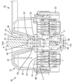
- the connector 10 of this embodiment includes a first housing 11 made of a synthetic resin (a housing that is a constituent element of the present invention) in which a plurality of wires 13 are led out from a wire lead-out surface 12, A synthetic resin wire cover 30 that is attached to one housing 11 and covers the wire lead-out surface 12, and is screwed with a tool 21 from the outer surface side of the wire cover 30, whereby the first housing 11 is moved to the second housing 23 (the present invention). And a bolt 17 to be assembled to a mating member).
- a synthetic resin a housing that is a constituent element of the present invention
- first terminal accommodating chambers 14 are formed inside the first housing 11 so as to vertically penetrate the first housing 11 with the wire lead-out surface 12 facing upward.
- a first terminal fitting 15 is inserted into each first terminal accommodating chamber 14 from above the first housing 11 (on the back side of the first housing 11).
- the electric wires 13 connected to the first terminal fittings 15 are led upward from the electric wire lead-out surface 12 (back surface) of the first housing 11.
- the first housing 11 is formed with a through hole 16 that vertically penetrates the central portion of the electric wire outlet surface 12.
- the bolt 17 includes a cylindrical main body 18, a hexagonal fitting part 19 (see FIG. 6) formed coaxially at the upper end of the main body 18, and coaxially downward from the lower end of the main body 18. It is comprised from the external thread part 20 extended.
- the bolt 17 has its main body 18 facing the through hole 16 with its axis 17A directed in the vertical direction (the direction in which both the housings 11 and 23 are fitted and the direction in which the electric wire cover 30 is assembled to the first housing 11). It is attached in the state fitted in.
- the attached bolt 17 is in a state in which relative displacement in the vertical direction is restricted with respect to the first housing 11 and rotation about the axis 17A is allowed.
- the fitting part 19 is arrange
- the male screw portion 20 protrudes downward from the front surface (lower surface) of the first housing 11.
- the bolt 17 is rotated by using an elongated tool 21 whose outer peripheral shape is a cylindrical shape.
- a hexagonal fitting hole 22 is formed coaxially on the inner periphery of the tip of the tool 21 (the lower end when fitted to the fitting portion 19).
- the fitting hole 22 of the tool 21 is fitted to the fitting portion 19, when the operation force in the rotation direction about the axis 21 ⁇ / b> A is applied to the tool 21, the tool 21 and the bolt 17 are integrated. It is designed to rotate.
- the second housing 23 has a plurality of second terminal accommodation chambers 24 corresponding to the first terminal accommodation chambers 14 of the first housing 11.
- a second terminal fitting 25 is accommodated in the second terminal accommodating chamber 24.
- a nut 26 is attached to the second housing 23 so as to correspond to the through hole 16 of the first housing 11 coaxially.
- the nut 26 attached to the second housing 23 is fixed in a state in which relative displacement in the axial direction (vertical direction) and rotation around the axial line are restricted with respect to the second housing 23.
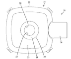
- the electric wire cover 30 is configured by integrally forming a cover main body 31 and a guide portion 36.
- the cover main body 31 is configured to rise upward from the outer peripheral edge of the wire lead-out surface 12 (in a direction away from the wire lead-out surface 12) in a state where the wire cover 30 is attached to the first housing 11.
- the outer peripheral wall portion 32 has a shape in which a part thereof in the circumferential direction is cut out, and a lead-out port 35 for leading the electric wire 13 turned in the electric wire cover 30 to the outside of the electric wire cover 30 is formed. Yes.
- the guide portion 36 extends from the upper edge portion of the opening edge of the outlet 35 to the outside of the wire cover main body 31. The electric wire 13 led out from the lead-out port 35 is taped along the guide portion 36.
- the cylindrical part 34 has a form in which the outer surface of the cover main body 31 (the electric wire cover 30) is recessed, and the recessed space serves as a work space 37 into which the tool 21 can be inserted.
- the fitting portion 19 is coaxially disposed on the bottom portion 38 (lower end portion) of the cylindrical portion 34 (work space 37). Between the outer periphery of the fitting part 19 and the inner peripheral surface of the cylindrical part 34, the clearance for accommodating the tool 21 in the state fitted on the fitting part 19 is ensured.
- the inner diameter dimension of the cylindrical portion 34 (work space 37) is minimum at the lower end (bottom 38) and maximum at the upper end. That is, the cylindrical portion 34 has a tapered shape in which the diameter dimension becomes smaller as the distance from the wire lead-out surface 12 becomes closer. And the upper end part in the inner periphery of the cylindrical part 34 (the opening edge part of the work space 37 on the outer surface of the electric wire cover 30 and the area farthest from the wire lead-out surface 12 in the cylindrical part 34) is on the entire periphery.
- An annular interference part 39 is formed. The technical significance of the interference unit 39 is as follows.
- the tool 21 should be fitted coaxially with the bolt 17. However, even if the axis 21 ⁇ / b> A of the tool 21 is inclined with respect to the axis 17 ⁇ / b> A of the bolt 17, If the inclination angle is not large, the tool 21 is fitted into the fitting portion 19 of the bolt 17, so that the bolt 17 can be screwed. When the bolt 17 is screwed while the tool 21 is inclined, the tool 21 turns in a constant path around the axis 17A of the bolt 17 in the work space 37.
- the tool 21 When such a turning motion occurs in the work space 37 (in the cylindrical portion 34), the tool 21 excessively presses the inner periphery of the cylindrical portion 34, so that the cylindrical portion 34 or the cylindrical shape in the electric wire cover 30 is used. There is a concern that an area other than the portion 34 may be illegally deformed or damaged.
- the angle formed by the axis 17A of the bolt 17 and the axis 21A of the tool 21 intersecting at the fitting portion 19 is As shown in FIG. 5, when the fitting part 19 and the tool 21 are at an angle at which the fitting part 19 and the tool 21 cannot be fitted beyond the range in which the tool 21 can be fitted into the fitting part 19 so that the bolt 17 can be screwed. Only in this way, the tool 21 interferes (contacts) with the interference part 39.
- the tool 21 comes to interfere with the interference portion 39 immediately after the tool 21 is able to be screwed into the fitting portion 19 from the state where the tool 21 can be screwed into the non-fitting state. ing.
- the tool 21 is in contact with a flange 52 (described later) at one end in the radial direction, and the other end in the radial direction is positioned at the upper end of the fitting portion 19. So as to be inclined.
- the angle formed between the axis 17 ⁇ / b> A of the bolt 17 and the axis 21 ⁇ / b> A of the tool 21 intersecting at the fitting portion 19 is relatively small, and the tool 21 is connected to the fitting portion 19 with respect to the bolt 17.
- the tool 21 does not interfere (contact) with the interference portion 39 when it is within a range where the screw can be fitted.
- the wire cover 30 is not likely to be adversely affected by the interference of the tool 21.
- the cylindrical portion 34 has a tapered shape in which the diameter dimension becomes smaller as it is closer to the wire lead-out surface 12. Therefore, when the electric wire cover 30 is assembled while being moved parallel to the housing so as to approach the electric wire outlet surface 12 from above, as shown in FIG. A plurality of electric wires 13 led out from the surface 12 are scraped. Therefore, there is no possibility that the electric wire 13 is caught between the tubular portion 34 and the electric wire outlet surface 12.
- the inner circumferential surface of the cylindrical portion 34 has an inclined surface 57 that decreases in a taper shape as it goes to the lower end side (the wire lead-out surface 12 side), and the most reduced diameter in the inclined surface 57. It consists of a sub-inclined surface 58 that expands in a curved shape from the inner bottom portion to the lower end opening edge of the bottom portion 38 (opening edge facing the wire lead-out surface 12).
- the bottom portion 38 of the cylindrical portion 34 has a thin shape toward the lower end side due to the sub-inclined surface 58.
- the cylindrical portion 34 has the inclined surface 57, a large working space 37 can be secured, and the bolt 17 can be shortened. Moreover, since the cylindrical part 34 has the sub-inclined surface 58, the fitting part 19 of the volt
- the first housing 11 is formed with a cylindrical mounting tube portion 51 that protrudes upward from the wire lead-out surface 12.
- the through hole 16 is disposed inside the mounting cylinder portion 51.
- a flange 52 is formed on the outer periphery of the lower end of the fitting portion 19 so as to extend over the entire circumference. As shown in FIG. 9, when the flange 52 abuts on the upper end opening edge 53 of the mounting cylinder portion 51, further tightening of the bolt 17 is prevented.
- the outer peripheral surface of the mounting cylinder portion 51 and the sub-inclined surface 58 have a lap region that faces each other in the radial direction in a state where the electric wire cover 30 is assembled.
- a radial gap 55 is formed between the surface and the sub-inclined surface 58.
- the gap 55 is configured to expand from the open end of the mounting cylinder portion 51 toward the base end side, which is the wire lead-out surface 12 side.
- the opening end of the mounting cylinder portion 51 is located at the same height as the inclined portion of the sub inclined surface 58 in the vertical direction.
- the first terminal fitting 15 is provided with a rubber plug 60 fitted to the terminal portion of the electric wire 13, and the rubber plug 60 is liquid-tight in the first terminal accommodating chamber 14. Contained. For this reason, the water that has reached the electric wire outlet surface 12 through the auxiliary inclined surface 58 is prevented from entering the first housing 11 by the rubber plug 60.
- first ribs 40 are formed on the outer peripheral surface of the cylindrical portion 34 (the surface facing the wire lead-out surface 12) at a position back to the interference portion 39.
- the 1st rib 40 is extended in the up-down direction in the several places spaced apart in the circumferential direction among the outer peripheral surfaces of the cylindrical part 34.
- the wire cover 30 is also formed with a second rib 41 along the inner surface of the upper wall portion 33 and the inner surface of the outer peripheral wall portion 32.
- the present invention is not limited to the embodiments described with reference to the above description and drawings.
- the following embodiments are also included in the technical scope of the present invention.
- the interference part was distribute
- the cross-sectional shape that intersects the axis of the cylindrical part is circular, but the cross-sectional shape that intersects the axis of the cylindrical part may be a polygon.
- the cylindrical portion is tapered, but the cylindrical portion may have a constant diameter.
Landscapes
- Details Of Connecting Devices For Male And Female Coupling (AREA)
Abstract
L'invention concerne l'incidence que l'interférence d'un outil peut avoir sur une couverture de fil électrique. Un connecteur (10) est pourvu : d'une couverture de fil électrique (30) qui recouvre une surface de sortie de fil électrique (12) dans un premier boîtier (11); d'un goujon (17) qui doit être manipulé par vissage par un outil (21) à partir du côté extérieur de la couverture de fil électrique (30); d'une section tubulaire (34) ayant une forme dans laquelle une surface de paroi extérieure de la couverture de fil électrique (30) est découpée de façon à permettre l'insertion de l'outil (21), ladite section tubulaire (34) possédant dans sa partie inférieure (38) une section (19) de verrouillage par outil (21) du goujon (17); d'une section d'interférence (39) formée dans la section tubulaire (34), ladite section d'interférence (39) permettant à l'outil (21) d'interférer avec la couverture de fil électrique (30) uniquement lorsque l'angle formé par l'intersection de l'axe (17A) du goujon (17) et de l'axe (21A) de l'outil (21), au niveau de la section de verrouillage (19) qui constitue le point de pivotement approximatif, est un angle de non verrouillage qui dépasse la plage de verrouillage sur laquelle l'outil (21) est en mesure de se verrouiller sur la section de verrouillage (19) d'une manière permettant le vissage du goujon (17).
Applications Claiming Priority (4)
| Application Number | Priority Date | Filing Date | Title |
|---|---|---|---|
| JP2011245982 | 2011-11-09 | ||
| JP2011-245982 | 2011-11-09 | ||
| JP2012-077793 | 2012-03-29 | ||
| JP2012077793A JP2013122900A (ja) | 2011-11-09 | 2012-03-29 | コネクタ |
Publications (1)
| Publication Number | Publication Date |
|---|---|
| WO2013069352A1 true WO2013069352A1 (fr) | 2013-05-16 |
Family
ID=48289738
Family Applications (1)
| Application Number | Title | Priority Date | Filing Date |
|---|---|---|---|
| PCT/JP2012/071063 Ceased WO2013069352A1 (fr) | 2011-11-09 | 2012-08-21 | Connecteur |
Country Status (2)
| Country | Link |
|---|---|
| JP (1) | JP2013122900A (fr) |
| WO (1) | WO2013069352A1 (fr) |
Cited By (2)
| Publication number | Priority date | Publication date | Assignee | Title |
|---|---|---|---|---|
| CN111326912A (zh) * | 2018-12-17 | 2020-06-23 | 住友电装株式会社 | 连接器嵌合体 |
| CN112703641A (zh) * | 2018-08-21 | 2021-04-23 | 株式会社自动网络技术研究所 | 电线盖及带电线盖连接器 |
Families Citing this family (3)
| Publication number | Priority date | Publication date | Assignee | Title |
|---|---|---|---|---|
| JP6191915B2 (ja) | 2013-10-29 | 2017-09-06 | 住友電装株式会社 | コネクタ |
| JP6620938B2 (ja) * | 2016-04-11 | 2019-12-18 | 住友電装株式会社 | コネクタ |
| JP7006577B2 (ja) * | 2018-12-17 | 2022-01-24 | 住友電装株式会社 | コネクタ嵌合体 |
Citations (4)
| Publication number | Priority date | Publication date | Assignee | Title |
|---|---|---|---|---|
| JPH06236783A (ja) * | 1993-02-10 | 1994-08-23 | Yazaki Corp | 多極コネクタの嵌合認識構造 |
| JPH1074558A (ja) * | 1996-08-30 | 1998-03-17 | Kansei Corp | 防水コネクタ |
| JP2001135419A (ja) * | 1999-11-09 | 2001-05-18 | Auto Network Gijutsu Kenkyusho:Kk | シールドケーブルの端末処理方法及び端末処理構造 |
| JP2004079487A (ja) * | 2002-08-22 | 2004-03-11 | Ryosei Electro-Circuit Systems Ltd | 電気コネクタの防水構造 |
Family Cites Families (1)
| Publication number | Priority date | Publication date | Assignee | Title |
|---|---|---|---|---|
| US5871373A (en) * | 1996-02-23 | 1999-02-16 | Labinal Components And Systems, Inc. | Electrical connector |
-
2012
- 2012-03-29 JP JP2012077793A patent/JP2013122900A/ja active Pending
- 2012-08-21 WO PCT/JP2012/071063 patent/WO2013069352A1/fr not_active Ceased
Patent Citations (4)
| Publication number | Priority date | Publication date | Assignee | Title |
|---|---|---|---|---|
| JPH06236783A (ja) * | 1993-02-10 | 1994-08-23 | Yazaki Corp | 多極コネクタの嵌合認識構造 |
| JPH1074558A (ja) * | 1996-08-30 | 1998-03-17 | Kansei Corp | 防水コネクタ |
| JP2001135419A (ja) * | 1999-11-09 | 2001-05-18 | Auto Network Gijutsu Kenkyusho:Kk | シールドケーブルの端末処理方法及び端末処理構造 |
| JP2004079487A (ja) * | 2002-08-22 | 2004-03-11 | Ryosei Electro-Circuit Systems Ltd | 電気コネクタの防水構造 |
Cited By (2)
| Publication number | Priority date | Publication date | Assignee | Title |
|---|---|---|---|---|
| CN112703641A (zh) * | 2018-08-21 | 2021-04-23 | 株式会社自动网络技术研究所 | 电线盖及带电线盖连接器 |
| CN111326912A (zh) * | 2018-12-17 | 2020-06-23 | 住友电装株式会社 | 连接器嵌合体 |
Also Published As
| Publication number | Publication date |
|---|---|
| JP2013122900A (ja) | 2013-06-20 |
Similar Documents
| Publication | Publication Date | Title |
|---|---|---|
| WO2013069352A1 (fr) | Connecteur | |
| EP2644910B1 (fr) | Boulon de connexion de connecteur, connecteur et ensemble connecteur | |
| JP6709513B2 (ja) | 端子台 | |
| US20240088613A1 (en) | Connector | |
| JP6709511B2 (ja) | 開口封止部材及び電気機器 | |
| CN110336145A (zh) | 插入式连接器壳体 | |
| JP6873171B2 (ja) | ケーブル実装アセンブリ | |
| CN104640743B (zh) | 配线装置 | |
| JP5631225B2 (ja) | 中継コネクタ | |
| JP2008010339A (ja) | コネクタ | |
| JP2006228463A (ja) | シールドコネクタ | |
| US10041852B2 (en) | Device for sensing a pressure of a fluid medium | |
| JP6071649B2 (ja) | 電気的素子のシール構造 | |
| JP5683257B2 (ja) | 中継コネクタ | |
| JP6191915B2 (ja) | コネクタ | |
| JP2017153868A (ja) | 美容器 | |
| JP5543637B1 (ja) | コネクタ | |
| JP6082648B2 (ja) | コネクタ | |
| JP6096599B2 (ja) | コネクタ装置 | |
| JP2015097147A (ja) | コネクタ | |
| JP5978163B2 (ja) | コネクタ装置 | |
| JP6757811B2 (ja) | プラグ接触アセンブリ | |
| JP5129658B2 (ja) | 端子防水構造を備えたスタータモータ | |
| JP4968529B2 (ja) | コネクタ | |
| JP2010232130A (ja) | コネクタ付き蓋の接続構造 |
Legal Events
| Date | Code | Title | Description |
|---|---|---|---|
| 121 | Ep: the epo has been informed by wipo that ep was designated in this application |
Ref document number: 12848175 Country of ref document: EP Kind code of ref document: A1 |
|
| NENP | Non-entry into the national phase |
Ref country code: DE |
|
| 122 | Ep: pct application non-entry in european phase |
Ref document number: 12848175 Country of ref document: EP Kind code of ref document: A1 |