WO2013069730A1 - 電気化学セル用包装材料 - Google Patents
電気化学セル用包装材料 Download PDFInfo
- Publication number
- WO2013069730A1 WO2013069730A1 PCT/JP2012/078990 JP2012078990W WO2013069730A1 WO 2013069730 A1 WO2013069730 A1 WO 2013069730A1 JP 2012078990 W JP2012078990 W JP 2012078990W WO 2013069730 A1 WO2013069730 A1 WO 2013069730A1
- Authority
- WO
- WIPO (PCT)
- Prior art keywords
- layer
- packaging material
- resin
- protective layer
- electrochemical cell
- Prior art date
- Legal status (The legal status is an assumption and is not a legal conclusion. Google has not performed a legal analysis and makes no representation as to the accuracy of the status listed.)
- Ceased
Links
Images


Classifications
-
- B—PERFORMING OPERATIONS; TRANSPORTING
- B32—LAYERED PRODUCTS
- B32B—LAYERED PRODUCTS, i.e. PRODUCTS BUILT-UP OF STRATA OF FLAT OR NON-FLAT, e.g. CELLULAR OR HONEYCOMB, FORM
- B32B15/00—Layered products comprising a layer of metal
- B32B15/04—Layered products comprising a layer of metal comprising metal as the main or only constituent of a layer, which is next to another layer of the same or of a different material
- B32B15/08—Layered products comprising a layer of metal comprising metal as the main or only constituent of a layer, which is next to another layer of the same or of a different material of synthetic resin
- B32B15/085—Layered products comprising a layer of metal comprising metal as the main or only constituent of a layer, which is next to another layer of the same or of a different material of synthetic resin comprising polyolefins
-
- B—PERFORMING OPERATIONS; TRANSPORTING
- B32—LAYERED PRODUCTS
- B32B—LAYERED PRODUCTS, i.e. PRODUCTS BUILT-UP OF STRATA OF FLAT OR NON-FLAT, e.g. CELLULAR OR HONEYCOMB, FORM
- B32B27/00—Layered products comprising a layer of synthetic resin
- B32B27/30—Layered products comprising a layer of synthetic resin comprising vinyl (co)polymers; comprising acrylic (co)polymers
- B32B27/304—Layered products comprising a layer of synthetic resin comprising vinyl (co)polymers; comprising acrylic (co)polymers comprising vinyl halide (co)polymers, e.g. PVC, PVDC, PVF, PVDF
-
- B—PERFORMING OPERATIONS; TRANSPORTING
- B32—LAYERED PRODUCTS
- B32B—LAYERED PRODUCTS, i.e. PRODUCTS BUILT-UP OF STRATA OF FLAT OR NON-FLAT, e.g. CELLULAR OR HONEYCOMB, FORM
- B32B27/00—Layered products comprising a layer of synthetic resin
- B32B27/38—Layered products comprising a layer of synthetic resin comprising epoxy resins
-
- B—PERFORMING OPERATIONS; TRANSPORTING
- B32—LAYERED PRODUCTS
- B32B—LAYERED PRODUCTS, i.e. PRODUCTS BUILT-UP OF STRATA OF FLAT OR NON-FLAT, e.g. CELLULAR OR HONEYCOMB, FORM
- B32B7/00—Layered products characterised by the relation between layers; Layered products characterised by the relative orientation of features between layers, or by the relative values of a measurable parameter between layers, i.e. products comprising layers having different physical, chemical or physicochemical properties; Layered products characterised by the interconnection of layers
- B32B7/04—Interconnection of layers
- B32B7/12—Interconnection of layers using interposed adhesives or interposed materials with bonding properties
-
- H—ELECTRICITY
- H01—ELECTRIC ELEMENTS
- H01M—PROCESSES OR MEANS, e.g. BATTERIES, FOR THE DIRECT CONVERSION OF CHEMICAL ENERGY INTO ELECTRICAL ENERGY
- H01M50/00—Constructional details or processes of manufacture of the non-active parts of electrochemical cells other than fuel cells, e.g. hybrid cells
- H01M50/10—Primary casings; Jackets or wrappings
- H01M50/116—Primary casings; Jackets or wrappings characterised by the material
- H01M50/117—Inorganic material
- H01M50/119—Metals
-
- H—ELECTRICITY
- H01—ELECTRIC ELEMENTS
- H01M—PROCESSES OR MEANS, e.g. BATTERIES, FOR THE DIRECT CONVERSION OF CHEMICAL ENERGY INTO ELECTRICAL ENERGY
- H01M50/00—Constructional details or processes of manufacture of the non-active parts of electrochemical cells other than fuel cells, e.g. hybrid cells
- H01M50/10—Primary casings; Jackets or wrappings
- H01M50/116—Primary casings; Jackets or wrappings characterised by the material
- H01M50/121—Organic material
-
- H—ELECTRICITY
- H01—ELECTRIC ELEMENTS
- H01M—PROCESSES OR MEANS, e.g. BATTERIES, FOR THE DIRECT CONVERSION OF CHEMICAL ENERGY INTO ELECTRICAL ENERGY
- H01M50/00—Constructional details or processes of manufacture of the non-active parts of electrochemical cells other than fuel cells, e.g. hybrid cells
- H01M50/10—Primary casings; Jackets or wrappings
- H01M50/116—Primary casings; Jackets or wrappings characterised by the material
- H01M50/124—Primary casings; Jackets or wrappings characterised by the material having a layered structure
-
- H—ELECTRICITY
- H01—ELECTRIC ELEMENTS
- H01M—PROCESSES OR MEANS, e.g. BATTERIES, FOR THE DIRECT CONVERSION OF CHEMICAL ENERGY INTO ELECTRICAL ENERGY
- H01M50/00—Constructional details or processes of manufacture of the non-active parts of electrochemical cells other than fuel cells, e.g. hybrid cells
- H01M50/10—Primary casings; Jackets or wrappings
- H01M50/116—Primary casings; Jackets or wrappings characterised by the material
- H01M50/124—Primary casings; Jackets or wrappings characterised by the material having a layered structure
- H01M50/1245—Primary casings; Jackets or wrappings characterised by the material having a layered structure characterised by the external coating on the casing
-
- H—ELECTRICITY
- H01—ELECTRIC ELEMENTS
- H01M—PROCESSES OR MEANS, e.g. BATTERIES, FOR THE DIRECT CONVERSION OF CHEMICAL ENERGY INTO ELECTRICAL ENERGY
- H01M50/00—Constructional details or processes of manufacture of the non-active parts of electrochemical cells other than fuel cells, e.g. hybrid cells
- H01M50/10—Primary casings; Jackets or wrappings
- H01M50/116—Primary casings; Jackets or wrappings characterised by the material
- H01M50/124—Primary casings; Jackets or wrappings characterised by the material having a layered structure
- H01M50/126—Primary casings; Jackets or wrappings characterised by the material having a layered structure comprising three or more layers
- H01M50/129—Primary casings; Jackets or wrappings characterised by the material having a layered structure comprising three or more layers with two or more layers of only organic material
-
- H—ELECTRICITY
- H01—ELECTRIC ELEMENTS
- H01M—PROCESSES OR MEANS, e.g. BATTERIES, FOR THE DIRECT CONVERSION OF CHEMICAL ENERGY INTO ELECTRICAL ENERGY
- H01M50/00—Constructional details or processes of manufacture of the non-active parts of electrochemical cells other than fuel cells, e.g. hybrid cells
- H01M50/10—Primary casings; Jackets or wrappings
- H01M50/131—Primary casings; Jackets or wrappings characterised by physical properties, e.g. gas permeability, size or heat resistance
- H01M50/133—Thickness
-
- H—ELECTRICITY
- H01—ELECTRIC ELEMENTS
- H01M—PROCESSES OR MEANS, e.g. BATTERIES, FOR THE DIRECT CONVERSION OF CHEMICAL ENERGY INTO ELECTRICAL ENERGY
- H01M10/00—Secondary cells; Manufacture thereof
- H01M10/05—Accumulators with non-aqueous electrolyte
- H01M10/052—Li-accumulators
-
- Y—GENERAL TAGGING OF NEW TECHNOLOGICAL DEVELOPMENTS; GENERAL TAGGING OF CROSS-SECTIONAL TECHNOLOGIES SPANNING OVER SEVERAL SECTIONS OF THE IPC; TECHNICAL SUBJECTS COVERED BY FORMER USPC CROSS-REFERENCE ART COLLECTIONS [XRACs] AND DIGESTS
- Y02—TECHNOLOGIES OR APPLICATIONS FOR MITIGATION OR ADAPTATION AGAINST CLIMATE CHANGE
- Y02E—REDUCTION OF GREENHOUSE GAS [GHG] EMISSIONS, RELATED TO ENERGY GENERATION, TRANSMISSION OR DISTRIBUTION
- Y02E60/00—Enabling technologies; Technologies with a potential or indirect contribution to GHG emissions mitigation
- Y02E60/10—Energy storage using batteries
Definitions
- the present invention relates to an electrochemical cell packaging material for packaging an electrochemical cell.
- Patent Document 1 A conventional packaging material for electrochemical cells is disclosed in Patent Document 1.
- This packaging material is a laminate in which an outermost base material layer, a barrier layer, and an innermost thermal adhesive layer are sequentially laminated, and the periphery of the electrochemical cell is heat-sealed with the thermal adhesive layers facing each other.
- a package is formed.
- the package is provided with a space for storing battery elements such as an electrolytic solution and a separator, and the storage space is formed by press-molding a packaging material cut into a rectangular shape.
- the packaging material when the electrolytic solution adheres to the upper surface of the packaging body when encapsulating the electrolytic solution composed of an alkyl carbonate ester (dimethyl carbonate, ethyl carbonate, etc.) and chlorine or fluorine-containing lithium salt inside the packaging body, There was a problem that the stretched nylon film of the base material layer was corroded (whitened) by the electrolyte solution, resulting in poor appearance.
- an alkyl carbonate ester dimethyl carbonate, ethyl carbonate, etc.
- chlorine or fluorine-containing lithium salt inside the packaging body
- an object of the present invention is to provide a packaging material for an electrochemical cell that is excellent in electrolytic solution resistance.
- the present invention provides a base layer composed of at least a resin film, a protective layer disposed on the outer layer to protect the base layer, and a heat composed of a thermoadhesive resin disposed on the innermost layer.
- An electrochemical cell packaging material comprising an adhesive layer and a barrier layer made of a metal foil disposed between the base material layer and the thermal adhesive layer, wherein the protective layer is bisphenol It is formed by an epoxy resin having A or bisphenol F as a unit in the skeleton.
- the protective layer formed of an epoxy resin having bisphenol A or bisphenol F as a unit in the skeleton has excellent electrolytic solution resistance and appearance due to resin cracking (whitening due to fine cracks) during molding (stretching). Defects can be prevented.
- the present invention also includes a base layer composed of at least a resin film, a protective layer disposed on the outer layer to protect the base layer, a thermal adhesive layer disposed on the innermost layer and composed of a thermoadhesive resin, and the base A packaging material for an electrochemical cell, which is formed by laminating a barrier layer made of a metal foil disposed between a material layer and the thermal adhesive layer, wherein the base material layer and the barrier layer are pigments It is characterized in that it is dry laminated with an adhesive containing bismuth and the protective layer is formed of an epoxy resin having bisphenol A or bisphenol F as a unit in the skeleton.
- the protective layer formed of an epoxy resin having bisphenol A or bisphenol F as a unit in the skeleton has excellent electrolytic solution resistance and prevents appearance defects due to resin cracking (whitening due to fine cracks) during molding (stretching). can do.
- the present invention also includes a base layer composed of at least a resin film, a protective layer disposed on the outer layer to protect the base layer, a thermal adhesive layer disposed on the innermost layer and composed of a thermoadhesive resin, and the base
- a packaging material for an electrochemical cell which is formed by laminating a barrier layer made of a metal foil disposed between a material layer and the thermal adhesive layer, wherein the base material layer and the barrier layer are pigments
- the protective layer is made of polyvinylidene chloride, vinylidene chloride-vinyl chloride copolymer, maleic anhydride-modified polypropylene, polyester resin, phenol resin, fluororesin, cellulose ester, olefin resin, urethane. It is formed of at least one resin selected from a resin and an acrylic resin.
- the pigment is contained in the adhesive that dry laminates the base material layer and the barrier layer, the inner layer side of the base material layer is colored. Also, at least one resin selected from polyvinylidene chloride, vinylidene chloride-vinyl chloride copolymer, maleic anhydride-modified polypropylene, polyester resin, phenol resin, fluororesin, cellulose ester, olefin resin, urethane resin, and acrylic resin
- the protective layer formed by is excellent in resistance to electrolytic solution.
- the present invention is characterized in that the protective layer is formed of a resin containing a photopolymerization initiator in a polyfunctional urethane acrylate having 5 or more acryloyl functional groups. According to this configuration, the protective layer is easily formed by light irradiation.
- the present invention is characterized in that the pigment is carbon black in the packaging material for an electrochemical cell having the above structure.
- the packaging material for electrochemical cells is colored black, and is particularly excellent in design.
- the present invention is characterized in that the protective layer contains a fine particle filler in the packaging material for an electrochemical cell having the above structure. According to this configuration, the appearance of the surface of the protective layer containing the fine particle filler is matted. Thereby, designability can be provided to the surface of the packaging material for electrochemical cells.
- the protective layer to which the fine particle filler is added is provided with lubricity on the surface, and the formability during press molding of the packaging material is stabilized.
- the present invention is characterized in that the fine particle filler is silica in the packaging material for an electrochemical cell having the above structure. According to this configuration, it is possible to prevent appearance defects due to resin cracking (whitening due to fine cracks) during molding (stretching).
- the present invention is characterized in that in the electrochemical cell packaging material having the above structure, a slip agent layer is provided on the surface of the protective layer.
- the present invention is also characterized in that the slip agent layer is made of a fatty acid amide resin in the packaging material for an electrochemical cell having the above-described configuration.
- a protective layer formed of an epoxy resin having bisphenol A or bisphenol F as a unit in the skeleton corrosion (whitening) of the base material layer due to adhesion of the electrolytic solution is prevented, and at the time of molding It is possible to provide a packaging material for electrochemical cells that does not cause poor appearance due to resin cracking (whitening due to fine cracks).
- the inner layer side of the base material layer is colored by dry laminating the base material layer and the barrier layer with an adhesive containing a pigment.
- the packaging material for electrochemical cells excellent in design can be provided by coloring.
- the present invention selected from polyvinylidene chloride, vinylidene chloride-vinyl chloride copolymer, maleic anhydride modified polypropylene, polyester resin, phenol resin, fluororesin, cellulose ester, olefin resin, urethane resin and acrylic resin.
- a protective layer formed of at least one kind is provided, and corrosion (whitening) of the base material layer due to adhesion of the electrolytic solution can be prevented.
- the inner layer side of the base material layer is colored by dry laminating the base material layer and the barrier layer with an adhesive containing a pigment. By coloring, the packaging material for electrochemical cells excellent in design can be provided.
- FIG. Schematic sectional view showing the layer structure of the packaging material according to the first embodiment of the present invention
- FIG. 1 is a perspective view of a lithium ion battery 121 according to an embodiment
- FIG. 2 is a cross-sectional view taken along line AA in FIG.
- the lithium ion battery 121 is configured by housing a lithium ion battery main body 122 containing an electrolyte in the package 120.
- the package 120 includes a storage portion 120a that stores the lithium ion battery main body 122 and a sheet portion 120b that covers the storage portion 120a.
- the package 120 has a heat bonding portion 120c at the peripheral edge where the storage portion 120a and the sheet portion 120b overlap, and is sealed inside. At this time, the positive electrode tab 123a and the negative electrode tab 123b connected to the lithium ion battery main body 122 extend outside while being sandwiched by the storage portion 120a and the sheet portion 120b with a tab film (not shown) interposed in the thermal bonding portion 120. ing.
- the lithium ion battery main body 122 is configured by a cell including a positive electrode made of a positive electrode active material and a positive electrode current collector, a negative electrode made of a negative electrode active material and a negative electrode current collector, and an electrolyte filled between the positive electrode and the negative electrode.
- the cell is formed by laminating a plurality of positive electrode plates from which a positive electrode current collector extends and negative electrode plates from which a negative electrode current collector extends. A plurality of positive plates and negative plates are alternately stacked via separators. The plurality of stacked positive electrode current collectors and negative electrode current collectors are overlapped and connected to a single positive electrode tab 123a and negative electrode tab 123b, respectively.
- FIG. 3 is a schematic cross-sectional view showing the layer structure of the packaging material 110 that forms the storage portion 120a and the sheet portion 120b.
- the packaging material 110 includes a protective layer 111, a base material layer 112, a barrier layer 114, and a thermal bonding layer 116. It is constructed by stacking sequentially.
- the base material layer 112 and the thin metal layer 114 are bonded via an adhesive layer 113, and the barrier layer 114 and the thermal adhesive layer 116 are bonded via an acid-modified polyolefin layer 115.
- the both surfaces of the barrier layer 114 are subjected to chemical conversion treatment, and the interlayer adhesion strength between the barrier layer 114 and the acid-modified polyolefin layer 115 and between the barrier layer 114 and the adhesive layer 113 is increased.
- the storage part 120a is produced by press-molding a packaging material 110 cut into a rectangular shape.
- the protective layer 111 side of the packaging material 110 is placed facing the concave female mold, and then cold-cooled to a predetermined molding depth with the male mold from the thermal adhesive layer 116 side. Mold.
- seat part 120b are thermally bonded by the thermobonding layer 116 which faces.
- the base material layer 112 imparts high puncture resistance (pinhole resistance), insulation, workability, and the like to the package 120, and is required to have a spreadability that can withstand press during embossing.
- the base material layer 112 can be arbitrarily selected from resin films or sheets such as stretched polyester resin or stretched nylon resin.
- polyester resin include polyethylene terephthalate, polybutylene terephthalate, polyethylene naphthalate, polybutylene naphthalate, copolymerized polyester, and polycarbonate.
- nylon resin include polyamide resin, that is, nylon 6, nylon 6,6, a copolymer of nylon 6 and nylon 6,6, nylon 6,10, polymetaxylylene adipamide (MXD6), and the like. .
- the base material layer 112 can be laminated with films of different materials in addition to a polyester film or a nylon film in order to improve pinhole resistance and insulation when used as a battery package.
- the protective layer 111 is disposed on the outer layer to protect the base material layer 112 and prevent the electrolytic solution from adhering and corroding (whitening).
- the protective layer 111 is formed of an epoxy resin having bisphenol A or bisphenol F as a unit in the skeleton. Accordingly, corrosion (whitening) due to the electrolytic solution can be prevented and appearance defects due to resin cracking (whitening due to fine cracks) during molding (stretching) can be prevented.
- Examples of the epoxy resin include those having bisphenol A or bisphenol F as a unit in the skeleton and obtained by repeated dehydrochlorination reaction and addition reaction of epichlorohydrin and bisphenol A or bisphenol F. Moreover, what is obtained by repeating the addition reaction between the epoxy compound which has 2 or more, preferably 2 glycidyl groups and bisphenol A or bisphenol F is also mentioned.
- epoxy compound examples include sorbitol polyglycidyl ether, polyglycerol polyglycidyl ether, pentaerythritol polyglycidyl ether, diglycerol polyglycidyl ether, trimethylolpropylene polyglycidyl ether, polyethylene glycol diglycidyl ether, polypropylene glycol diglycidyl ether, and the like. Is mentioned.
- the epoxy equivalent of the epoxy resin (the amount of chemical formula of the epoxy resin per epoxy group, in other words, the value obtained by dividing the molecular weight of the epoxy resin by the number of epoxy groups contained in the epoxy resin) is not particularly limited. Is preferably in the range of ⁇ 5000. When the epoxy equivalent is 5000 or more, the coating film appearance may be inferior.
- an epoxy resin obtained by repeating an addition reaction between an amino group and a glycidyl group is also known, but it is generally not preferable because of poor chemical resistance.
- the barrier layer 114 is made of a metal foil and prevents water vapor from entering the lithium ion battery 121 from the outside.
- aluminum having a thickness of 15 ⁇ m or more is used in order to stabilize pinholes of the barrier layer 114 and processability (pouching, embossing formability) and to have pinhole resistance.
- the material of aluminum used as the barrier layer 114 should be such that the iron content is 0.3 to 9.0% by weight, preferably 0.7 to 2.0% by weight. Is desirable.
- the package 120 is less likely to generate pinholes due to bending.
- the side wall can be easily formed when the packaging material 110 is embossed.
- the iron content of aluminum is less than 0.3% by weight, effects such as prevention of generation of pinholes and improvement of embossing formability are not recognized.
- the iron content of aluminum exceeds 9.0% by weight, the flexibility as aluminum is hindered, and the bag-making property as a packaging material is deteriorated.
- aluminum manufactured by cold rolling of the barrier layer 114 changes its flexibility, waist strength and hardness under annealing (so-called annealing treatment) conditions.
- the aluminum of the barrier layer 114 is preferably aluminum that has been annealed and tends to be softer than a hard-treated product that has not been annealed.
- the chemical conversion treatment is formed on the surface of the barrier layer 114 by a chromium or non-chromium system.
- chromium conversion treatment include chromate chromate treatment, phosphoric acid chromate treatment, and coating type chromate treatment.
- non-chromium (coating type) chemical conversion treatment include chemical conversion treatment of zirconium, titanium, zinc phosphate and the like. At this time, it is more preferable to use a coating-type chemical conversion treatment from the viewpoint that continuous treatment is possible and a water washing step is unnecessary and the treatment cost can be reduced. In particular, it is most preferable to treat with a treatment liquid containing an aminated phenol polymer, a trivalent chromium compound, and a phosphorus compound.
- a known coating method such as a bar coating method, a roll coating method, a gravure coating method, a dipping method or the like may be selected as the processing solution.
- a known degreasing method such as an alkali dipping method, an electrolytic cleaning method, an acid cleaning method, or an acid activation method before the chemical conversion treatment.
- the thermal adhesive layer 116 is disposed on the innermost layer of the packaging material 110 and is made of a thermal adhesive resin that melts by heat and fuses the opposing packaging materials 110 to each other.
- the resin type differs depending on whether or not a tab film is interposed between the thermal adhesive layer 116 and the positive electrode tab 123a or the negative electrode tab 123b.
- a tab film is interposed, a film made of a simple substance or a mixture of olefinic resins may be used.
- a film made of an acid-modified olefin resin graft-modified with an unsaturated carboxylic acid may be used.
- Polypropylene is preferably used as the thermal adhesive layer 116, but a single layer or a single layer or a multilayer of linear low density polyethylene or medium density polyethylene, or a blend of linear low density polyethylene or medium density polyethylene, or It can also be used as a multilayer film.
- polypropylene that is, random propylene, homopropylene, block propylene, and linear low density polyethylene, medium density polyethylene, low crystalline ethylene-butene copolymer, low crystalline propylene-butene copolymer, A terpolymer composed of a three-component copolymer of ethylene, butene, and propylene, silica, zeolite, an antiblocking agent (AB agent) such as acrylic resin beads, a fatty acid amide slip agent, and the like may be added.
- AB agent antiblocking agent
- the acid-modified polyolefin layer 115 is a resin layer that stably bonds the barrier layer 114 and the thermal adhesive layer 116, and acid-modified polypropylene is preferably used.
- the acid-modified polyolefin layer 115 needs to be appropriately selected and used depending on the resin type used for the thermal bonding layer 116.
- a polyolefin resin graft-modified with an unsaturated carboxylic acid a copolymer of ethylene and acrylic acid graft-modified with an unsaturated carboxylic acid, an unsaturated carboxylic acid
- Graft-modified copolymer of propylene and acrylic acid copolymer of ethylene and methacrylic acid graft-modified with unsaturated carboxylic acid, copolymer of propylene and methacrylic acid graft-modified with unsaturated carboxylic acid
- metal cross-linked polyolefin resins graft-modified with saturated carboxylic acids There are metal cross-linked polyolefin resins graft-modified with saturated carboxylic acids.
- a butene component an ethylene-propylene-butene copolymer, an amorphous ethylene-propylene copolymer, a propylene- ⁇ -olefin copolymer, etc. may be added to these resins. Good.
- a homotype having a bigat softening point of 115 ° C or higher and a melting point of 150 ° C or higher (2) A copolymer of ethylene-propylene having a bigat softening point of 105 ° C or higher and a melting point of 130 ° C or higher (random copolymer type) (3) A simple substance or a blended product obtained by acid-modified polymerization using an unsaturated carboxylic acid having a melting point of 110 ° C. or higher can be used.
- the adhesive layer 113 is a resin layer that firmly bonds the base material layer 112 and the barrier layer 114.
- Such interlayer adhesion can be performed by a dry lamination method, an extrusion lamination method, a coextrusion lamination method, a thermal lamination method, or the like.
- polyester When laminating by the dry laminating method, polyester, polyethyleneimine, polyether, cyanoacrylate, urethane, organic titanium, polyetherurethane, epoxy, polyesterurethane, imide, isocyanate
- Various adhesives based on polyolefin, polyolefin, and silicone can be used.
- the protective layer 111 is formed of epoxy resin with bisphenol A or bisphenol F as a unit in the skeleton, the electrolytic solution resistance of the protective layer 111 is excellent and resin cracking (fine) during molding (stretching) Appearance defect due to whitening due to cracks).
- the packaging material 110 for electrochemical cells which is excellent in electrolyte solution resistance and does not cause appearance defects due to resin cracking during molding (stretching) can be provided.
- different layers may be interposed between the layers.
- an electrochemical cell body other than the lithium ion battery body 122 may be packaged with a package 120 made of the packaging material 110 to produce an electric cell other than the lithium ion battery 121. .
- electrochemical cells include nickel metal hydride batteries, nickel cadmium batteries, lithium metal primary batteries or secondary batteries, chemical batteries such as lithium polymer batteries, electric double layer capacitors, capacitors, and electrolytic capacitors.
- the electrochemical cell body is a positive electrode composed of a positive electrode active material and a positive electrode current collector before enclosing packaging material, a negative electrode composed of a negative electrode active material and a negative electrode current collector, and an electrolyte filled between the positive electrode and the negative electrode.
- all electric device elements that generate electric energy such as a cell (power storage unit) including electrode terminals connected to a positive electrode and a negative electrode in the cell.
- FIG. 4 is a cross-sectional view showing an electrochemical cell packaging material 110 of a packaging body 120 according to the second embodiment.
- the same reference numerals are given to the same descriptions as those of the first embodiment shown in FIGS.
- the base material layer 112 and the barrier layer 114 are bonded by the dry lamination method through the adhesive layer 113, and a pigment is added to the adhesive of the adhesive layer 113.
- the adhesive layer 113 is a layer that adheres the base material layer 112 and the barrier layer 114 by a dry lamination method, and a pigment is added to the adhesive.
- the adhesive for the adhesive layer 113 include a polyvinyl acetate adhesive, a polyacrylate adhesive, a cyanoacrylate adhesive, an ethylene copolymer adhesive, a cellulose adhesive, a polyester adhesive, and a polyamide adhesive.
- the polyacrylic ester adhesive is made of a homopolymer such as ethyl acrylate, butyl, 2-ethylhexyl ester, or a copolymer of these with methyl methacrylate, acrylonitrile, styrene or the like.
- the ethylene copolymer adhesive comprises a copolymer of ethylene and a monomer such as vinyl acetate, ethyl acrylate, acrylic acid or methacrylic acid.
- the amino resin adhesive is made of urea resin or melamine resin.
- the rubber adhesive is made of chloroprene rubber, nitrile rubber, styrene-butadiene rubber or the like.
- the inorganic adhesive is made of alkali metal silicate, low melting point glass or the like.
- Carbon black is used for the pigment contained in the adhesive of the adhesive layer 113, and the adhesive layer 113 is colored black. Thereby, the external appearance of the packaging material 110 is identified as black through the protective layer 111 and the base material layer 112 having transparency.
- the adhesive layer 113 is preferably composed of an adhesive to which carbon black as a pigment is added in a solid content of 5 wt% to 30 wt%, preferably 10 wt% to 25 wt%.
- the addition amount of a pigment is less than 5 weight%, the color to be colored becomes light and the design on appearance is poor.
- the addition amount of a pigment exceeds 30 weight%, the adhesive strength of the base material layer 112 and the barrier layer 114 will become weak. As a result, the base layer 112 contracts so as to return to its original shape due to heat applied in the sealing step after molding, and the base layer 112 and the barrier layer 114 are peeled off to cause floating and wrinkles. .
- a chromatic coloring pigment or an inorganic coloring pigment can be used as the coloring pigment.
- the chromatic color pigment include azo pigments, phthalocyanine pigments, and condensed polycyclic pigments.
- the azo pigments include soluble pigments such as watching red and carmine 6C, and insoluble azo pigments such as monoazo yellow, disazo yellow, pyrazolone orange, red, and permanent red.
- the phthalocyanine pigment include copper phthalocyanine pigments
- examples of the metal-free phthalocyanine pigment include blue pigments or green pigments
- examples of the condensed polycyclic pigment include dioxazine violet and quinacridone violet.
- titanium oxide can be used in addition to carbon black.
- the adhesive layer 113 can be colored with a pearl pigment or a fluorescent pigment.
- pearl pigment pearl powder or powder of the inner part of the shell was used classically, but now the outer side of the fine flakes (flakes) is coated with a metal oxide or a mixture of metal oxides Is used.
- the fine flakes include mica flakes, talc flakes, kaolin flakes, bismuth oxychloride flakes, glass flakes, SiO 2 flakes, synthetic ceramic flakes, and the like.
- metal oxides covering the outside of these fine flakes include TiO 2 , Fe 2 O 3 , SnO 2 , Cr 2 O 3 , and ZnO.
- those in which the outside of mica flakes, glass flakes, and SiO 2 flakes are coated with TiO 2 or Fe 2 O 3 are desirable. It may also be coated with TiO 2 and Fe 2 O 3.
- Fluorescent pigments are phosphors, that is, substances that emit luminescence in a broad sense, and include both inorganic fluorescent pigments and organic fluorescent pigments.
- the inorganic fluorescent pigment can be obtained by baking by adding an activator mainly containing oxide crystals such as Ca, Ba, Mg, Zn, and Cd.
- the main component may be a crystal of sulfide such as Ca, Ba, Mg, Zn, or Cd, a crystal of silicate, a crystal of phosphate, or a crystal of tungstate.
- the activator metal elements such as Mn, Zn, Ag, Cu, Sb, and Pb or rare earth elements such as lanthanoids can be used.
- Desirable phosphors include ZnO: Zn, Br 5 (PO 4 ) 3 Cl: Eu, Zn 2 GeO 4 : Mn, Y 2 O 3 : Eu, Y (P, V) O 4 : Eu, Y 2 O 2 Si: Eu, etc. can be exemplified.
- Organic fluorescent pigments include diaminostilbene disulfonic acid derivatives, imidazole derivatives, coumarin derivatives, triazole derivatives, carbazole derivatives, pyridine derivatives, naphthalic acid derivatives, imidazolone derivatives, dyes (fluorescein, eosin, etc.), etc.
- a compound having a benzene ring (such as anthracene) can be used.
- the protective layer 111 is formed of an epoxy resin having bisphenol A or bisphenol F as a unit in the skeleton as in the first embodiment, thereby preventing corrosion (whitening) due to the electrolytic solution and resin cracking (fine) during molding (stretching). Appearance failure due to whitening due to cracks.
- the protective layer 111 can be used as long as it has resistance to the electrolytic solution.
- it is formed of at least one selected from polyvinylidene chloride, vinylidene chloride-vinyl chloride copolymer, maleic anhydride-modified polypropylene, polyester, phenol resin, fluororesin, cellulose ester, olefin resin, urethane resin, and acrylic resin. be able to. Thereby, corrosion (whitening) by electrolyte solution can be prevented.
- the protective layer 111 By forming the protective layer 111 with a resin containing a photopolymerization initiator in a polyfunctional urethane acrylate having 5 or more acryloyl group functional groups, the protective layer can be easily formed by light irradiation.
- the content ratio of the photofunctional group in the polyfunctional urethane acrylate is 50 to 95%.
- Polyfunctional urethane acrylate is obtained by reacting polyfunctional acrylate having active hydrogen with polyisocyanate.
- the polyisocyanate is usually in the range of 0.1 to 50 equivalents, preferably in the range of 0.1 to 10 equivalents, as the isocyanate group equivalent, relative to 1 equivalent of the active hydrogen group in the polyfunctional acrylate having active hydrogen.
- the reaction temperature is usually in the range of 30 to 150 ° C., preferably 50 to 100 ° C.
- the end point of the reaction is calculated by a method in which the amount of residual isocyanate is reacted with an excess of n-butylamine and back titrated with 1N hydrochloric acid. At this time, the time when the isocyanate becomes 0.5% by weight or less is terminated.
- photopolymerization initiator examples include benzoins such as benzoin, benzoin methyl ether, benzoin ethyl ether, benzoin propyl ether, and benzoin isobutyl ether; acetophenone, 2,2-diethoxy-2-phenylacetophenone, 1,1-dichloroacetophenone, 2-hydroxy-2-methyl-phenylpropan-1-one, diethoxyacetophenone, 1-hydroxycyclohexyl phenyl ketone, 2-methyl-1- [4- (methylthio) phenyl] -2-morpholinopropan-1-one Acetophenones such as 2-ethylanthraquinone, 2-t-butylanthraquinone, 2-chloroanthraquinone, 2-amylanthraquinone and the like; 2,4-diethylthioxanthone, 2-i Thioxanthones such as propylthioxanthone and 2-ch
- the amount of the photopolymerization initiator component used is 0.1 wt% or more and 10 wt% or less, preferably 1 wt% or more and 7 wt%, when the solid content of the resin composition of the protective layer 111 is 100 wt%. It is as follows.
- the inner layer side of the base material layer 112 is colored by dry laminating the base material layer 112 and the barrier layer 114 with an adhesive (adhesive layer 113) containing a pigment.
- the protective layer 111 is made of polyvinylidene chloride, vinylidene chloride-vinyl chloride copolymer, maleic anhydride-modified polypropylene, polyester resin, phenol resin, fluororesin, cellulose ester, olefin resin, urethane resin, acrylic resin, which have excellent electrolytic solution resistance. It is formed of at least one selected from resins. Thereby, the outer layer side of the base material layer 112 colored on the inner layer side can be prevented from being corroded (whitened) by the electrolytic solution.
- the protective layer 111 is formed of an epoxy resin composition having bisphenol A or bisphenol F as a unit in the skeleton, corrosion (whitening) due to the electrolytic solution can be prevented and molding (stretching) can be prevented. Appearance defects due to resin cracking (whitening due to fine cracks) can be prevented.
- the protective layer 111 is formed of a resin containing a photopolymerization initiator in a polyfunctional urethane acrylate having 5 or more functional groups of acryloyl groups, the protective layer can be easily formed by light irradiation. it can.
- FIG. 5 is a cross-sectional view showing an electrochemical cell packaging material 110 of a packaging body 120 according to the third embodiment.
- the same reference numerals are given to the same explanations as those in the first and second embodiments shown in FIGS.
- a fine particle filler 111a having an average particle size of 0.2 to 3 ⁇ m by a Coulter counter method is added.
- the appearance of the surface of the protective layer 111 containing the fine particle filler 111a is matted.
- the protective layer 111 to which the fine particle filler 111a has been added has lubricity on the surface, and the formability during the press molding of the packaging material 110 is stabilized.
- the fine particle filler 111a inorganic materials such as silica, acrylic, alumina, barium sulfate, calcium carbonate, titanium oxide, acrylic beads, and the like can be used.
- the silica fine particle filler 111a is preferable because resin cracking (whitening due to fine cracks) hardly occurs when the packaging material 110 is press-molded. If the average particle size of the fine particle filler 111a is smaller than 0.2 ⁇ m, sufficient lubricity cannot be obtained. On the other hand, if the average particle size is larger than 3 ⁇ m, the resin composition of the protective layer 111 becomes brittle.
- the content ratio of the filler 111a in the resin composition of the protective layer 111 is desirably 5% by weight or more and 50% by weight or less.
- the content ratio of the filler 111a is 5% by weight or more, a certain level of lubricity can be imparted to the surface of the protective layer 111.
- the content ratio of the fine particle filler 111a is 50% by weight or less, film roughness on the surface of the protective layer 111 can be prevented. Thereby, the external appearance defect of the packaging material 110 for electrochemical cells can be prevented.
- the Coulter counter method is one of measuring methods for particle size and particle size distribution. Specifically, when a partition wall having one small hole is provided in the electrolytic solution and a voltage is applied with electrodes placed on both sides thereof, current flows, but the resistance is determined by the volume of the small hole portion of the partition wall. When the filler 111a is dispersed in the electrolyte solution to form a thin suspension and sucked from one of the partition walls, the particles pass through the small holes. At this time, the electrolyte decreases by the volume, and the electrical resistance increases. Accordingly, the amount of change in resistance indicates the particle volume, and the number of occurrences of resistance change indicates particles. Thereby, a particle size distribution is obtained.
- the appearance of the surface of the protective layer 111 containing the fine particle filler 111a is matt and has a design property.
- lubricity is imparted to the surface of the protective layer 111, and the formability during press molding of the packaging material 110 is stabilized.
- the protective layer 111 is less likely to cause an appearance defect due to resin cracking (whitening due to fine cracks).
- FIG. 6 is a cross-sectional view showing the packaging material 110 for an electrochemical cell of the package 120 according to the second embodiment.
- a slip agent layer 117 is provided on the surface of the protective layer 111 of the packaging material 110 of the present embodiment.
- FIG. 6 is an explanatory view showing a process of press-molding the packaging material 110 for an electrochemical cell.
- the packaging body 120 of the lithium ion battery 121 is to be an embossed type
- the sheet-shaped packaging material 110 cut into a predetermined shape is press-molded to form the storage portion 120a.
- the press molding is performed while inserting the male mold 21 into a female mold 22 having a side wall in the periphery and opening at the top, and sandwiching the packaging material 110.
- the packaging material 110 is placed so that the slip agent layer 117 comes into contact with the inner surface 22a side of the female die 22, and is pressed by the male die 21 from the thermal adhesive layer 116 side. Thereby, a side wall is formed in the packaging material 110 while drawing the periphery of the packaging material 110 into the female mold 22. At this time, the packaging material 110 follows the deformation of the thin metal layer 114 and the other resin layers are deformed. For this reason, if the sliding property between the base material layer 112 and the inner surface of the female die 22 is low, there is a problem that the base material layer 112 cannot follow the deformation of the metal foil 114 and breaks. Further, this problem is more likely to occur as the side wall height (molding depth) of the accommodating portion 120a formed by press molding increases.
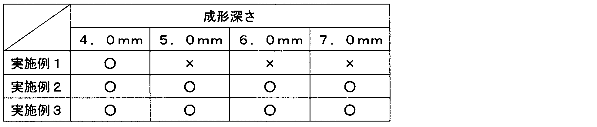
- the slip agent layer 117 is provided on the surface of the protective layer 111. Therefore, the slipperiness between the female die 22 and the base material layer 112 is indirectly stabilized via the slip agent layer 117. Accordingly, the limit molding depth of the moldable packaging material 110 increases and stable emboss molding becomes possible.
- the slip agent layer 117 is formed by, for example, diluting a fatty acid amide in a solvent such as isopropyl alcohol, ethyl acetate, toluene, methyl-ethyl-ketone to a concentration of 0.1 to 10% by roll coating or spraying.
- a solvent such as isopropyl alcohol, ethyl acetate, toluene, methyl-ethyl-ketone
- a solvent such as isopropyl alcohol, ethyl acetate, toluene, methyl-ethyl-ketone
- a solvent such as isopropyl alcohol, ethyl acetate, toluene, methyl-ethyl-ketone
- a slip agent may be coated or sprayed on the entire surface of the protective layer 111, or only a portion to be embossed in the mold may be coated or sprayed.
- the packaging material 110 can be coated or sprayed and stored in advance, but more excellent moldability can be obtained by coating or spraying immediately before molding.
- Both sides of aluminum are subjected to chemical conversion treatment, and one of the chemical conversion treatment surfaces is provided with a stretched nylon film (thickness 25 ⁇ m) through a polyester adhesive so that the adhesive layer has a thickness of about 4 ⁇ m. Bonding was performed by a dry laminating method. Next, acid-modified polypropylene (thickness: 23 ⁇ m, hereinafter abbreviated as acid-modified PP) and polypropylene (thickness: 23 ⁇ m, hereinafter abbreviated as PP) were coextruded and laminated on the other chemical conversion treated surface. A protective layer was formed on the top surface of the stretched nylon film.
- the chemical conversion treatment layer was coated with a treatment liquid composed of a phenol resin, a chromium fluoride compound, and phosphoric acid by a roll coating method, and baked under conditions where the film temperature was 180 ° C. or higher.
- the coating amount of chromium was 10 mg / m 2 (dry weight).
- the packaging material for electrochemical cells according to Example 1 was coated with an epoxy resin having bisphenol A as a unit in the skeleton at a coating amount of 2.5 g / m 2 on the upper surface of the base material layer of the packaging material for electrochemical cells. After drying, it was heated at 190 ° C. for 2 minutes to form a cured film, which was used as a protective layer.
- the packaging material for an electrochemical cell according to Example 2 is protected by applying erucamide to the upper surface of the protective layer of the packaging material for the electrochemical cell of Example 1 at a coating amount of 0.2 mg / m 2 by a gravure printing method.
- a slip agent layer was provided on the upper surface of the layer.
- the packaging material for an electrochemical cell according to Example 3 was obtained by applying ethylenebisoleic acid amide to the upper surface of the protective layer of the packaging material for electrochemical cell of Example 1 at a coating amount of 0.2 mg / m 2 by gravure printing. A slip agent layer was provided on the upper surface of the protective layer.
- the packaging material for electrochemical cells according to Comparative Example 1 has an application amount of 2.5 g / m 2 of an epoxy resin having hexamethylenediamine as a unit in the skeleton on the upper surface of the base material layer of the packaging material for electrochemical cells. After coating and drying, a cured film was formed by heating at 190 ° C. for 2 minutes to form a protective layer.
- the packaging material for electrochemical cells according to Comparative Example 2 was coated with a polyester resin to which a curing agent containing an isocyanate group was added on the upper surface of the base material layer of the packaging material for electrochemical cells at a coating amount of 2.5 g / m 2 . Then, after drying, it was heated at 45 ° C. for 3 days to form a cured film, which was used as a protective layer.
- the packaging material for electrochemical cells according to Comparative Example 3 was coated with an acrylic resin to which a curing agent containing an isocyanate group was added on the upper surface of the base material layer of the packaging material for electrochemical cells at a coating amount of 2.5 g / m 2 . Then, after drying, it was heated at 45 ° C. for 3 days to form a cured film, which was used as a protective layer.
- the packaging material for electrochemical cells according to Comparative Example 4 was coated with an olefin-based resin added with a curing agent containing an isocyanate group on the upper surface of the base material layer of the packaging material for electrochemical cells at a coating amount of 2.5 g / m 2 . Then, after drying, it was heated at 45 ° C. for 3 days to form a cured film to obtain a protective layer.
- Example production of packaging material for electrochemical cells 2
- Both sides of aluminum are subjected to chemical conversion treatment, and one of the chemical conversion treatment surfaces is provided with a stretched nylon film (thickness 25 ⁇ m) through a polyester adhesive so that the adhesive layer has a thickness of about 4 ⁇ m. Bonding was performed by a dry laminating method. Next, acid-modified polypropylene (thickness: 23 ⁇ m, hereinafter abbreviated as acid-modified PP) and polypropylene (thickness: 23 ⁇ m, hereinafter abbreviated as PP) were coextruded and laminated on the other chemical conversion treatment surface. A protective layer was formed on the top surface of the stretched nylon film.
- a treatment liquid composed of a phenol resin, a chromium fluoride compound, and phosphoric acid was applied as a treatment liquid by a roll coating method, and baked under conditions where the film temperature was 180 ° C. or higher.
- the coating amount of chromium was 10 mg / m 2 (dry weight).
- the packaging material for an electrochemical cell according to Example 4 was obtained by applying an epoxy resin having bisphenol A as a unit in the skeleton at a coating amount of 2.5 g / m 2 on the upper surface of the base material layer of the packaging material for an electrochemical cell, After drying, it was heated at 190 ° C. for 2 minutes to form a cured film, which was used as a protective layer.
- the packaging material for an electrochemical cell according to Example 6 was coated with an acrylic resin added with a curing agent containing an isocyanate group on the upper surface of the base material layer of the packaging material for an electrochemical cell at a coating amount of 2.5 g / m 2 . Then, after drying, it was heated at 45 ° C. for 3 days to form a cured film, which was used as a protective layer.
- an acrylic resin added with a curing agent containing an isocyanate group
- the packaging material for an electrochemical cell according to Example 7 was coated with an olefin resin added with a curing agent containing an isocyanate group on the upper surface of the base material layer of the packaging material for an electrochemical cell at a coating amount of 2.5 g / m 2 . Then, after drying, it was heated at 45 ° C. for 3 days to form a cured film, which was used as a protective layer.
- Example 8
- the packaging material for an electrochemical cell according to Example 8 was coated with a polyfunctional urethane acrylate having 5 functional groups of acryloyl group containing 3% by weight of a photopolymerization initiator on the upper surface of the base material layer of the packaging material for an electrochemical cell. After coating with an amount of 2.5 g / m 2 and drying, a cured film was formed by irradiation with a high-pressure mercury lamp having an energy of 100 W / cm 2 for 5 seconds, and this was used as a protective layer. [Example 9]
- the packaging material for an electrochemical cell according to Example 9 was coated with a polyfunctional urethane acrylate having 6 functional groups of acryloyl group containing 3% by weight of a photopolymerization initiator on the upper surface of the base material layer of the packaging material for an electrochemical cell. After coating with an amount of 2.5 g / m 2 and drying, a cured film was formed by irradiation with a high-pressure mercury lamp having an energy of 100 W / cm 2 for 5 seconds, and this was used as a protective layer. [Example 10]
- the electrochemical cell packaging material according to Example 10 was prepared by adding 15% by weight of fine particles of barium sulfate having an average particle size of 0.7 ⁇ m to the upper surface of the base material layer of the electrochemical cell packaging material and bisphenol A as a skeleton. An epoxy resin having a unit therein was applied at a coating amount of 2.5 g / m 2 , dried and then heated at 190 ° C. for 2 minutes to form a cured film, which was used as a protective layer. [Example 11]
- Example 12 In the electrochemical cell packaging material according to Example 11, 15% by weight of fine calcium carbonate having an average particle size of 0.7 ⁇ m is added to the upper surface of the base material layer of the electrochemical cell packaging material, and bisphenol A is used as a skeleton. An epoxy resin having a unit therein was applied at a coating amount of 2.5 g / m 2 , dried and then heated at 190 ° C. for 2 minutes to form a cured film, which was used as a protective layer. [Example 12]
- the packaging material for an electrochemical cell according to Example 12 was obtained by applying erucamide to the upper surface of the protective layer of the packaging material for an electrochemical cell of Example 5 at a coating amount of 0.2 mg / m 2 by a gravure printing method.
- a slip agent layer was provided on the upper surface of the protective layer.
- the packaging material for electrochemical cells according to Example 13 was coated with ethylenebisoleic acid amide on the upper surface of the protective layer of the packaging material for electrochemical cells in Example 5 at a coating amount of 0.2 mg / m 2 by gravure printing. Thus, a slip agent was provided on the upper surface of the protective layer.
- the packaging material for electrochemical cells according to Comparative Example 5 is an epoxy resin having hexamethylenediamine as a unit in the skeleton on the upper surface of the base material layer of the packaging material for electrochemical cells at a coating amount of 2.5 g / m 2 . After coating and drying, a cured film was formed by heating at 190 ° C. for 2 minutes to form a protective layer.
- the packaging material for an electrochemical cell according to Comparative Example 6 was coated with a polyfunctional urethane acrylate having 3 functional groups of acryloyl group containing 3% by weight of a photopolymerization initiator on the upper surface of the base material layer of the packaging material for electrochemical cell. After coating with an amount of 2.5 g / m 2 and drying, a cured film was formed by irradiation with a high-pressure mercury lamp having an energy of 100 W / cm 2 for 5 seconds, and this was used as a protective layer. [Comparative Example 7]
- the packaging material for electrochemical cells according to Comparative Example 7 is coated with polyfunctional urethane acrylate having 4 functional groups of acryloyl group containing 3% by weight of a photopolymerization initiator on the upper surface of the base material layer of the packaging material for electrochemical cells. After coating with an amount of 2.5 g / m 2 and drying, a cured film was formed by irradiation with a high-pressure mercury lamp having an energy of 100 W / cm 2 for 5 seconds, and this was used as a protective layer. [Evaluation of electrolyte resistance]
- the packaging materials according to Examples 1 to 5, 10 to 13 were cut to 150 mm ⁇ 60 mm, and the surface of the protective layer or the surface of the slip agent layer was applied with a load of 100 g.
- the coefficient of dynamic friction was measured with HEIDON TYPE 14 (trade name) manufactured by Kagaku Corporation. The measurement speed is 100 mm / min.
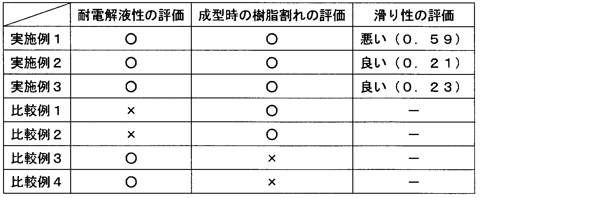
- Tables 1 and 3 [Evaluation of proper molding process]
- the packaging materials according to Examples 1 to 5, 10 to 13 are cut into 80 mm ⁇ 120 mm to produce strip pieces.
- the strip piece is placed on the molding die (female die) so that the thermal adhesive layer is located on the molding die (male die) side, and the strip piece is pressed with a pressing pressure (surface pressure) of 0.16 MPa.
- the molding die (male die) has a rectangular shape of 55 mm ⁇ 32 mm (corner R: 2 mm, ridge line R: 1 mm), and the molding die (female die) has a clearance of 0.3 mm from the male die.
- Examples 2 and 3 in which a slip agent layer was provided on the surface of the protective layer had a dynamic friction coefficient of 0.25 or less, and were superior in slipperiness to Example 1 in which no slip agent layer was provided.
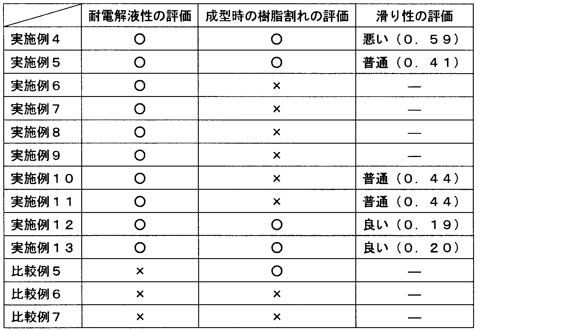
- the packaging materials according to Examples 4, 5, 12, and 13 were not observed to be whitened on the surface on the protective layer side when the electrolytic solution was dropped ( ⁇ ), and were press-molded (stretched). No resin cracking (whitening due to fine cracks) was observed ( ⁇ ).
- the packaging materials according to Examples 6 to 11 no whitening was observed on the surface of the protective layer due to the dropping of the electrolytic solution ( ⁇ ), but resin cracking during press molding (stretching) (whitening due to fine cracks) ) was observed ( ⁇ ).
- whitening was observed on the surface on the protective layer side when the electrolytic solution was dropped ( ⁇ ).
- Examples 5, 10, and 11 to which the fine particle filler was added had a dynamic friction coefficient of 0.50 or less, and were more slippery than Example 4 to which the fine particle filler was not added.
- Examples 12 and 13 in which a slip agent layer was provided on the surface of the protective layer had a coefficient of dynamic friction of 0.25 or less, and were superior in slipperiness to Example 5 in which no slip agent was provided.
- Examples 5, 10, and 11 to which the fine particle filler was added were excellent in molding process suitability compared with Example 4 to which the fine particle filler was not added.
- Examples 12 and 13 in which the slip agent layer was provided on the surface of the protective layer were excellent in molding process suitability as compared with Example 5 in which the slip agent layer was not provided.
- the present invention can be used as a package for packaging chemical batteries such as nickel metal hydride batteries, nickel cadmium batteries, lithium metal primary batteries, secondary batteries, lithium polymer batteries, and electric double layer capacitors, capacitors, and electrolytic capacitors.
- chemical batteries such as nickel metal hydride batteries, nickel cadmium batteries, lithium metal primary batteries, secondary batteries, lithium polymer batteries, and electric double layer capacitors, capacitors, and electrolytic capacitors.
Landscapes
- Chemical & Material Sciences (AREA)
- Chemical Kinetics & Catalysis (AREA)
- Electrochemistry (AREA)
- General Chemical & Material Sciences (AREA)
- Inorganic Chemistry (AREA)
- Engineering & Computer Science (AREA)
- Manufacturing & Machinery (AREA)
- Sealing Battery Cases Or Jackets (AREA)
- Laminated Bodies (AREA)
- Electric Double-Layer Capacitors Or The Like (AREA)
Abstract
Description
以下、図面を参照しながら本発明の第1実施形態に係る電気化学セル用包装材料110について説明する。図1は一実施形態のリチウムイオン電池121の斜視図であり、図2は図1中のA-A線断面図である。
(1)ビガット軟化点115℃以上、融点150℃以上のホモタイプ
(2)ビガット軟化点105℃以上、融点130℃以上のエチレンープロピレンとの共重合体(ランダム共重合タイプ)
(3)融点110℃以上である不飽和カルボン酸を用い酸変性重合した単体又はブレンド物等を用いることができる。
図4は第2実施形態に係る包装体120の電気化学セル用包装材料110を示す断面図である。説明の便宜上、前述の図1~図3に示す第1実施形態と同様の説明には同一の符号を付している。本実施形態の包装材料110は基材層112とバリア層114とを接着層113を介してドライラミネート法により接着し、接着層113の接着剤には顔料が添加されている。
図5は第3実施形態に係る包装体120の電気化学セル用包装材料110を示す断面図である。説明の便宜上、前述の図1~図4に示す第1、第2実施形態と同様の説明には同一の符号を付している。本実施形態の包装材料110の保護層111にはコールターカウンター法による平均粒径が0.2~3μmの微粒子フィラー111aが添加されている。これにより、微粒子フィラー111aを含有する保護層111の表面は外観が艶消しされる。また、微粒子フィラー111aが添加された保護層111は表面に滑性が付与され、包装材料110のプレス成形時における成形性が安定する。
図6は第2実施形態に係る包装体120の電気化学セル用包装材料110を示す断面図である。説明の便宜上、前述の図1~図4に示す第1、第2実施形態と同様の説明には同一の符号を付している。本実施形態の包装材料110の保護層111表面にはスリップ剤層117が設けられている。
[電気化学セル用包装材料のサンプル作製1]
[実施例1]
[実施例2]
[実施例3]
[比較例1]
[比較例2]
[比較例3]
[比較例4]
[電気化学セル用包装材料のサンプル作製2]
[実施例4]
[実施例5]
[実施例6]
[実施例7]
[実施例8]
[実施例9]
[実施例10]
[実施例11]
[実施例12]
[実施例13]
[比較例5]
[比較例6]
[比較例7]
[耐電解液性の評価]
[成型時の樹脂割れの評価]
[滑り性の評価]
[成型加工適正の評価]

111 保護層
112 基材層
113 接着層
114 バリア層
115 酸変性ポリオレフィン層
116 熱接着層
117 スリップ剤層
120 包装体
120a 収納部
120b シート部
121 リチウムイオン電池
122 リチウムイオン電池本体
123a 正極タブ
123b 負極タブ
Claims (9)
- 少なくとも樹脂フィルムからなる基材層と、外層に配して前記基材層を保護する保護層と、最内層に配して熱接着性樹脂からなる熱接着層と、前記基材層と前記熱接着層との間に配して金属箔からなるバリア層と、を積層して構成される電気化学セル用包装材料であって、前記保護層がビスフェノールAもしくはビスフェノールFを骨格中の単位として有するエポキシ樹脂により形成されることを特徴とする電気化学セル用包装材料。
- 少なくとも樹脂フィルムからなる基材層と、外層に配して前記基材層を保護する保護層と、最内層に配して熱接着性樹脂からなる熱接着層と、前記基材層と前記熱接着層との間に配して金属箔からなるバリア層と、を積層して構成される電気化学セル用包装材料であって、前記基材層と前記バリア層とが顔料を含有する接着剤によりドライラミネート接着され、前記保護層がビスフェノールAもしくはビスフェノールFを骨格中の単位として有するエポキシ樹脂により形成されることを特徴とする電気化学セル用包装材。
- 少なくとも樹脂フィルムからなる基材層と、外層に配して前記基材層を保護する保護層と、最内層に配して熱接着性樹脂からなる熱接着層と、前記基材層と前記熱接着層との間に配して金属箔からなるバリア層と、を積層して構成される電気化学セル用包装材料であって、前記基材層と前記バリア層とが顔料を含有する接着剤によりドライラミネート接着され、前記保護層がポリ塩化ビニリデン、塩化ビニリデン-塩化ビニル共重合体、無水マレイン酸変性ポリプロピレン、ポリエステル樹脂、フェノール樹脂、フッ素樹脂、セルロースエステル、オレフィン樹脂、ウレタン樹脂及びアクリル樹脂から選ばれた少なくとも1種の樹脂で形成されることを特徴とする電気化学セル用包装材料。
- 前記保護層がアクリロイル基の官能基数が5以上の多官能ウレタンアクリレートに光重合開始剤を含有する樹脂により形成されていることを特徴とする請求項3に記載の電気化学セル用包装材料。
- 前記顔料がカーボンブラックであることを特徴とする請求項2~請求項4のいずれかに記載の電気化学セル用包装材料。
- 前記保護層は微粒子フィラーを含有することを特徴とする請求項2~請求項5のいずれかに記載の電気化学セル用包装材料。
- 前記微粒子フィラーがシリカであることを特徴とする請求項6に記載の電気化学セル用包装材料。
- 前記保護層表面にスリップ剤層が設けられていることを特徴とする請求項1~請求項7のいずれかに記載のリチウムイオン電池用包装材料。
- 前記スリップ剤層が脂肪酸アマイド系樹脂からなることを特徴とする請求項8に記載のリチウムイオン電池用包装材料。
Priority Applications (5)
| Application Number | Priority Date | Filing Date | Title |
|---|---|---|---|
| US14/353,198 US10673030B2 (en) | 2011-11-11 | 2012-11-08 | Electrochemical cell packaging material |
| EP12846874.1A EP2779265B1 (en) | 2011-11-11 | 2012-11-08 | Electrochemical cell packaging material |
| CN201280055432.1A CN103931013B (zh) | 2011-11-11 | 2012-11-08 | 电化学电池用包装材料 |
| KR1020147012441A KR101537399B1 (ko) | 2011-11-11 | 2012-11-08 | 전기화학 셀용 포장재료 |
| EP15185114.4A EP2993714B1 (en) | 2011-11-11 | 2012-11-08 | Electrochemical cell packaging material |
Applications Claiming Priority (8)
| Application Number | Priority Date | Filing Date | Title |
|---|---|---|---|
| JP2011247876 | 2011-11-11 | ||
| JP2011-247876 | 2011-11-11 | ||
| JP2011289057 | 2011-12-28 | ||
| JP2011-289057 | 2011-12-28 | ||
| JP2012-014130 | 2012-01-26 | ||
| JP2012014126A JP5293845B2 (ja) | 2011-11-11 | 2012-01-26 | 電気化学セル用包装材料 |
| JP2012014130A JP5293846B2 (ja) | 2011-12-28 | 2012-01-26 | 電気化学セル用包装材料 |
| JP2012-014126 | 2012-01-26 |
Publications (1)
| Publication Number | Publication Date |
|---|---|
| WO2013069730A1 true WO2013069730A1 (ja) | 2013-05-16 |
Family
ID=51147969
Family Applications (1)
| Application Number | Title | Priority Date | Filing Date |
|---|---|---|---|
| PCT/JP2012/078990 Ceased WO2013069730A1 (ja) | 2011-11-11 | 2012-11-08 | 電気化学セル用包装材料 |
Country Status (5)
| Country | Link |
|---|---|
| US (1) | US10673030B2 (ja) |
| EP (2) | EP2993714B1 (ja) |
| KR (1) | KR101537399B1 (ja) |
| CN (3) | CN107017358A (ja) |
| WO (1) | WO2013069730A1 (ja) |
Cited By (8)
| Publication number | Priority date | Publication date | Assignee | Title |
|---|---|---|---|---|
| KR20150043991A (ko) | 2013-10-15 | 2015-04-23 | 쇼와 덴코 패키징 가부시키가이샤 | 성형용 포장재 |
| WO2015152216A1 (ja) * | 2014-03-31 | 2015-10-08 | 大日本印刷株式会社 | 電池用包装材料 |
| JP2015195089A (ja) * | 2014-03-31 | 2015-11-05 | 大日本印刷株式会社 | 電池用包装材料 |
| JP2015195090A (ja) * | 2014-03-31 | 2015-11-05 | 大日本印刷株式会社 | 電池用包装材料 |
| CN105556699A (zh) * | 2013-09-20 | 2016-05-04 | 大日本印刷株式会社 | 电池用包装材料 |
| WO2021033708A1 (ja) * | 2019-08-20 | 2021-02-25 | 大日本印刷株式会社 | 蓄電デバイス用外装材の成形工程における品質管理方法、蓄電デバイスの製造方法、蓄電デバイス用外装材、及び蓄電デバイス |
| WO2024111604A1 (ja) * | 2022-11-21 | 2024-05-30 | 大日本印刷株式会社 | 蓄電デバイス用外装材、その製造方法、及び蓄電デバイス |
| US12065591B2 (en) | 2020-01-10 | 2024-08-20 | Resonac Packaging Corporation | Packaging material for molding |
Families Citing this family (28)
| Publication number | Priority date | Publication date | Assignee | Title |
|---|---|---|---|---|
| US10644271B1 (en) | 2013-01-08 | 2020-05-05 | Rutgers, The State University Of New Jersey | Packaging material for electrochemical cells |
| JP6245704B2 (ja) * | 2013-09-03 | 2017-12-13 | 大日精化工業株式会社 | ポリウレタン系樹脂組成物及びリチウムイオン電池用外装体 |
| JP6254933B2 (ja) * | 2014-12-26 | 2017-12-27 | 大日精化工業株式会社 | 樹脂組成物及びリチウムイオン電池用外装体 |
| US10547033B2 (en) * | 2015-03-27 | 2020-01-28 | Dai Nippon Printing Co., Ltd. | Packaging material for batteries, and battery |
| JP6708979B2 (ja) * | 2015-03-30 | 2020-06-10 | 凸版印刷株式会社 | 蓄電デバイス用外装材 |
| CN108604649B (zh) | 2016-02-18 | 2022-04-01 | 凸版印刷株式会社 | 蓄电装置用封装材料以及蓄电装置用封装材料的制造方法 |
| JP6754589B2 (ja) * | 2016-02-29 | 2020-09-16 | 藤森工業株式会社 | 樹脂被覆金属積層体、電池外装体及び電池 |
| JP6935991B2 (ja) * | 2016-06-24 | 2021-09-15 | 昭和電工パッケージング株式会社 | 蓄電デバイス用外装材及び蓄電デバイス |
| US11038227B2 (en) * | 2016-09-20 | 2021-06-15 | Apple Inc. | Battery pouch including nanoceramic coating |
| JP2018055976A (ja) * | 2016-09-29 | 2018-04-05 | 昭和電工パッケージング株式会社 | 包装材及びその製造方法 |
| CN106299168A (zh) * | 2016-10-27 | 2017-01-04 | 明冠新材料股份有限公司 | 一种涂覆型高性能铝塑膜及其制备方法 |
| CN106505162A (zh) * | 2016-10-27 | 2017-03-15 | 明冠新材料股份有限公司 | 一种复合型高性能铝塑膜及其制备方法 |
| KR101894449B1 (ko) | 2016-12-01 | 2018-09-03 | 율촌화학 주식회사 | 셀 파우치 및 이의 제조 방법 |
| TWI629820B (zh) * | 2017-04-17 | 2018-07-11 | 華碩電腦股份有限公司 | 電池包覆膜及其製造方法 |
| WO2019190285A1 (ko) * | 2018-03-30 | 2019-10-03 | 주식회사 엘지화학 | 플렉시블 이차전지용 패키징 및 그를 포함하는 플렉시블 이차전지 |
| KR102034315B1 (ko) * | 2018-05-17 | 2019-10-21 | 주식회사 스위스 | 내구성이 향상된 이차 전지용 알루미늄 파우치 필름 |
| KR102109554B1 (ko) | 2018-08-08 | 2020-05-12 | 한밭대학교 산학협력단 | 중대형 이차전지용 알루미늄 파우치 필름 제조방법 |
| KR102109550B1 (ko) | 2018-08-08 | 2020-05-12 | 한밭대학교 산학협력단 | 소형 이차전지용 알루미늄 파우치 필름 제조장치 및 이에 의해 제조된 파우치 필름 |
| CN109119551A (zh) * | 2018-08-08 | 2019-01-01 | 广东莱尔新材料科技股份有限公司 | 一种锂电池软包装用的铝塑膜及其制备工艺 |
| CN109546016A (zh) * | 2018-10-31 | 2019-03-29 | 上海恩捷新材料科技有限公司 | 电化学电池用包装膜及其制备方法 |
| CN113226753B (zh) * | 2018-12-28 | 2023-05-30 | 大日本印刷株式会社 | 蓄电装置用外包装材料、其制造方法和蓄电装置 |
| KR20220006555A (ko) * | 2019-05-15 | 2022-01-17 | 도판 인사츠 가부시키가이샤 | 축전 디바이스용 외장재 |
| CN110437686B (zh) * | 2019-08-30 | 2021-02-26 | 厦门长塑实业有限公司 | 一种耐电解液bopa薄膜及其制备方法 |
| JP7391201B2 (ja) * | 2019-11-08 | 2023-12-04 | エルジー エナジー ソリューション リミテッド | 架橋ポリオレフィンを含むリチウム二次電池用の架橋分離膜及びその製造方法 |
| CN112143017B (zh) * | 2020-08-28 | 2023-04-07 | 广东安德力新材料有限公司 | 一种用于动力电池铝塑膜的尼龙层及其制备工艺 |
| CN112009057B (zh) * | 2020-08-28 | 2023-03-28 | 广东安德力新材料有限公司 | 一种用于动力电池的复合铝塑膜 |
| KR102493563B1 (ko) | 2020-10-12 | 2023-01-31 | 주식회사 탑앤씨 | 리튬이온 이차전지용 파우치 필름의 제조방법 |
| CN115991957A (zh) * | 2022-12-29 | 2023-04-21 | 乐凯胶片股份有限公司 | 涂料、铝塑膜和锂电池 |
Citations (6)
| Publication number | Priority date | Publication date | Assignee | Title |
|---|---|---|---|---|
| JP2001068074A (ja) * | 1999-08-27 | 2001-03-16 | Mitsubishi Chemicals Corp | 電 池 |
| JP2001260275A (ja) * | 2000-03-14 | 2001-09-25 | Mitsubishi Chemicals Corp | 積層体 |
| JP2002352778A (ja) * | 2001-05-23 | 2002-12-06 | Dainippon Printing Co Ltd | 電池用包装材料 |
| JP2003007261A (ja) * | 2001-06-20 | 2003-01-10 | Dainippon Printing Co Ltd | 電池用包装材料 |
| JP2008288117A (ja) | 2007-05-21 | 2008-11-27 | Showa Denko Packaging Co Ltd | 電池ケース用包材及び電池用ケース |
| JP2011054563A (ja) * | 2009-08-07 | 2011-03-17 | Dainippon Printing Co Ltd | 電気化学セル用包装材 |
Family Cites Families (16)
| Publication number | Priority date | Publication date | Assignee | Title |
|---|---|---|---|---|
| EP1102336B1 (en) * | 1999-04-08 | 2007-09-12 | Dai Nippon Printing Co., Ltd. | Lithium battery packaging laminated multilayer structure |
| US6472065B1 (en) * | 2000-07-13 | 2002-10-29 | 3M Innovative Properties Company | Clear adhesive sheet |
| JP2002056823A (ja) * | 2000-08-10 | 2002-02-22 | Dainippon Printing Co Ltd | 電池用積層フィルムおよびそれを用いた電池用容器 |
| US20070196619A1 (en) * | 2001-08-16 | 2007-08-23 | Carter Jeffrey T | Flexible polymer element for a curable composition |
| AU2001280117A1 (en) * | 2000-08-24 | 2002-03-04 | Kanto Nok Hanbai Co., Ltd. | Case for electronic parts |
| US20020164441A1 (en) * | 2001-03-01 | 2002-11-07 | The University Of Chicago | Packaging for primary and secondary batteries |
| DE60237501D1 (de) | 2001-06-20 | 2010-10-14 | Dainippon Printing Co Ltd | Batterieverpackungsmaterial |
| JP2004256781A (ja) * | 2003-02-28 | 2004-09-16 | Toshiba Corp | コーティング用エポキシ樹脂組成物およびそれを用いた電子機器 |
| JP2006036900A (ja) * | 2004-07-27 | 2006-02-09 | Arakawa Chem Ind Co Ltd | 保護コート用樹脂組成物及び無色透明な保護膜 |
| JP5080738B2 (ja) * | 2005-12-20 | 2012-11-21 | 新日鉄マテリアルズ株式会社 | 樹脂被覆ステンレス鋼箔,容器及び2次電池 |
| JP5211462B2 (ja) | 2006-03-31 | 2013-06-12 | 大日本印刷株式会社 | 電池用包装材料及びその製造方法 |
| EP1981099B1 (en) * | 2007-03-30 | 2012-10-03 | Dai Nippon Printing Co., Ltd. | Packaging material for flat electrochemical cell |
| JP4766057B2 (ja) | 2008-01-23 | 2011-09-07 | ソニー株式会社 | 非水電解質電池および非水電解質電池の製造方法 |
| JP5401794B2 (ja) * | 2008-01-29 | 2014-01-29 | ソニー株式会社 | 電池パック |
| JP5347411B2 (ja) | 2008-09-30 | 2013-11-20 | 大日本印刷株式会社 | 電気化学セル用包装材料 |
| US9312520B2 (en) * | 2009-08-07 | 2016-04-12 | Dai Nippon Printing Co., Ltd. | Electrochemical cell packaging material |
-
2012
- 2012-11-08 CN CN201710167010.8A patent/CN107017358A/zh active Pending
- 2012-11-08 EP EP15185114.4A patent/EP2993714B1/en active Active
- 2012-11-08 US US14/353,198 patent/US10673030B2/en active Active
- 2012-11-08 CN CN201280055432.1A patent/CN103931013B/zh active Active
- 2012-11-08 WO PCT/JP2012/078990 patent/WO2013069730A1/ja not_active Ceased
- 2012-11-08 CN CN201610008644.4A patent/CN105619914B/zh active Active
- 2012-11-08 EP EP12846874.1A patent/EP2779265B1/en active Active
- 2012-11-08 KR KR1020147012441A patent/KR101537399B1/ko active Active
Patent Citations (6)
| Publication number | Priority date | Publication date | Assignee | Title |
|---|---|---|---|---|
| JP2001068074A (ja) * | 1999-08-27 | 2001-03-16 | Mitsubishi Chemicals Corp | 電 池 |
| JP2001260275A (ja) * | 2000-03-14 | 2001-09-25 | Mitsubishi Chemicals Corp | 積層体 |
| JP2002352778A (ja) * | 2001-05-23 | 2002-12-06 | Dainippon Printing Co Ltd | 電池用包装材料 |
| JP2003007261A (ja) * | 2001-06-20 | 2003-01-10 | Dainippon Printing Co Ltd | 電池用包装材料 |
| JP2008288117A (ja) | 2007-05-21 | 2008-11-27 | Showa Denko Packaging Co Ltd | 電池ケース用包材及び電池用ケース |
| JP2011054563A (ja) * | 2009-08-07 | 2011-03-17 | Dainippon Printing Co Ltd | 電気化学セル用包装材 |
Non-Patent Citations (1)
| Title |
|---|
| See also references of EP2779265A4 |
Cited By (22)
| Publication number | Priority date | Publication date | Assignee | Title |
|---|---|---|---|---|
| CN105556699B (zh) * | 2013-09-20 | 2020-06-09 | 大日本印刷株式会社 | 电池用包装材料 |
| US10033021B2 (en) | 2013-09-20 | 2018-07-24 | Dai Nippon Printing Co., Ltd. | Packaging material for cell |
| CN105556699A (zh) * | 2013-09-20 | 2016-05-04 | 大日本印刷株式会社 | 电池用包装材料 |
| EP3048655A4 (en) * | 2013-09-20 | 2016-12-07 | Dainippon Printing Co Ltd | PACKAGING MATERIAL FOR BATTERIES |
| CN104553147B (zh) * | 2013-10-15 | 2017-11-28 | 昭和电工包装株式会社 | 成型用包装材料 |
| CN104553147A (zh) * | 2013-10-15 | 2015-04-29 | 昭和电工包装株式会社 | 成型用包装材料 |
| KR20150043991A (ko) | 2013-10-15 | 2015-04-23 | 쇼와 덴코 패키징 가부시키가이샤 | 성형용 포장재 |
| US9553284B2 (en) | 2013-10-15 | 2017-01-24 | Showa Denko Packaging Co., Ltd. | Molding material for package |
| US10199613B2 (en) | 2014-03-31 | 2019-02-05 | Dai Nippon Printing Co., Ltd. | Packaging material for batteries |
| JP2015195090A (ja) * | 2014-03-31 | 2015-11-05 | 大日本印刷株式会社 | 電池用包装材料 |
| JP2015195089A (ja) * | 2014-03-31 | 2015-11-05 | 大日本印刷株式会社 | 電池用包装材料 |
| WO2015152216A1 (ja) * | 2014-03-31 | 2015-10-08 | 大日本印刷株式会社 | 電池用包装材料 |
| CN114342160A (zh) * | 2019-08-20 | 2022-04-12 | 大日本印刷株式会社 | 蓄电器件用外包装材料的成形工序中的品质管理方法、蓄电器件的制造方法、蓄电器件用外包装材料和蓄电器件 |
| JP6849162B1 (ja) * | 2019-08-20 | 2021-03-24 | 大日本印刷株式会社 | 蓄電デバイス用外装材の成形工程における品質管理方法、蓄電デバイスの製造方法、蓄電デバイス用外装材、及び蓄電デバイス |
| JP2021093375A (ja) * | 2019-08-20 | 2021-06-17 | 大日本印刷株式会社 | 蓄電デバイス用外装材の成形工程における品質管理方法、蓄電デバイスの製造方法、蓄電デバイス用外装材、及び蓄電デバイス |
| WO2021033708A1 (ja) * | 2019-08-20 | 2021-02-25 | 大日本印刷株式会社 | 蓄電デバイス用外装材の成形工程における品質管理方法、蓄電デバイスの製造方法、蓄電デバイス用外装材、及び蓄電デバイス |
| CN114342160B (zh) * | 2019-08-20 | 2024-12-10 | 大日本印刷株式会社 | 蓄电器件用外包装材料的成形工序中的品质管理方法、蓄电器件的制造方法、蓄电器件用外包装材料和蓄电器件 |
| JP7676821B2 (ja) | 2019-08-20 | 2025-05-15 | 大日本印刷株式会社 | 蓄電デバイス用外装材の成形工程における品質管理方法、蓄電デバイスの製造方法、蓄電デバイス用外装材、及び蓄電デバイス |
| JP2025111711A (ja) * | 2019-08-20 | 2025-07-30 | 大日本印刷株式会社 | 蓄電デバイス用外装材の成形工程における品質管理方法、蓄電デバイスの製造方法、蓄電デバイス用外装材、及び蓄電デバイス |
| JP7816615B2 (ja) | 2019-08-20 | 2026-02-18 | 大日本印刷株式会社 | 蓄電デバイス用外装材の成形工程における品質管理方法、蓄電デバイスの製造方法、蓄電デバイス用外装材、及び蓄電デバイス |
| US12065591B2 (en) | 2020-01-10 | 2024-08-20 | Resonac Packaging Corporation | Packaging material for molding |
| WO2024111604A1 (ja) * | 2022-11-21 | 2024-05-30 | 大日本印刷株式会社 | 蓄電デバイス用外装材、その製造方法、及び蓄電デバイス |
Also Published As
| Publication number | Publication date |
|---|---|
| KR101537399B1 (ko) | 2015-07-16 |
| KR20140082791A (ko) | 2014-07-02 |
| CN105619914A (zh) | 2016-06-01 |
| CN107017358A (zh) | 2017-08-04 |
| EP2993714A1 (en) | 2016-03-09 |
| CN103931013A (zh) | 2014-07-16 |
| CN103931013B (zh) | 2017-07-11 |
| US10673030B2 (en) | 2020-06-02 |
| EP2993714B1 (en) | 2019-03-06 |
| EP2779265B1 (en) | 2018-07-18 |
| EP2779265A1 (en) | 2014-09-17 |
| US20140335403A1 (en) | 2014-11-13 |
| CN105619914B (zh) | 2018-01-23 |
| EP2779265A4 (en) | 2015-12-02 |
Similar Documents
| Publication | Publication Date | Title |
|---|---|---|
| JP6249062B2 (ja) | 電気化学セル用包装材料 | |
| KR101537399B1 (ko) | 전기화학 셀용 포장재료 | |
| JP7283093B2 (ja) | 電池用包装材料、その製造方法、及び電池 | |
| JP5601265B2 (ja) | 電気化学セル用包装材料 | |
| JP5110132B2 (ja) | 電気化学セル用包装材 | |
| CN103907219B (zh) | 电化学电池用包装材料 | |
| JP6019812B2 (ja) | 電気化学セル用包装材料 | |
| JP6446950B2 (ja) | 電池用包装材料 | |
| JP5293845B2 (ja) | 電気化学セル用包装材料 | |
| JP7306429B2 (ja) | 電池用包装材料、その製造方法、及び電池 | |
| JP7314970B2 (ja) | 電池用包装材料、その製造方法及び電池 | |
| CN105720217A (zh) | 蓄电设备用外包装材料及蓄电设备 | |
| JP4993051B2 (ja) | リチウムイオン電池用包装材料およびその製造方法 | |
| US20170033324A1 (en) | Packaging material for power storage device | |
| CN103348504A (zh) | 电池外壳用层叠体和二次电池 | |
| JP5761278B2 (ja) | 電池用包装材料のシーラント層用の樹脂組成物 | |
| JP5310922B1 (ja) | 電気化学セル用包装材料 | |
| JP6252648B2 (ja) | 電気化学セル用包装材料 | |
| JP6275080B2 (ja) | 電池用包装材料のシーラント層用の樹脂組成物 | |
| JP6171620B2 (ja) | 電気化学セル用包装材料 |
Legal Events
| Date | Code | Title | Description |
|---|---|---|---|
| 121 | Ep: the epo has been informed by wipo that ep was designated in this application |
Ref document number: 12846874 Country of ref document: EP Kind code of ref document: A1 |
|
| WWE | Wipo information: entry into national phase |
Ref document number: 14353198 Country of ref document: US |
|
| ENP | Entry into the national phase |
Ref document number: 20147012441 Country of ref document: KR Kind code of ref document: A |
|
| NENP | Non-entry into the national phase |
Ref country code: DE |
|
| WWE | Wipo information: entry into national phase |
Ref document number: 2012846874 Country of ref document: EP |