WO2013069747A1 - モータ駆動装置 - Google Patents
モータ駆動装置 Download PDFInfo
- Publication number
- WO2013069747A1 WO2013069747A1 PCT/JP2012/079030 JP2012079030W WO2013069747A1 WO 2013069747 A1 WO2013069747 A1 WO 2013069747A1 JP 2012079030 W JP2012079030 W JP 2012079030W WO 2013069747 A1 WO2013069747 A1 WO 2013069747A1
- Authority
- WO
- WIPO (PCT)
- Prior art keywords
- motor
- phase
- duty
- current
- drive device
- Prior art date
- Legal status (The legal status is an assumption and is not a legal conclusion. Google has not performed a legal analysis and makes no representation as to the accuracy of the status listed.)
- Ceased
Links
Images












Classifications
-
- H—ELECTRICITY
- H02—GENERATION; CONVERSION OR DISTRIBUTION OF ELECTRIC POWER
- H02P—CONTROL OR REGULATION OF ELECTRIC MOTORS, ELECTRIC GENERATORS OR DYNAMO-ELECTRIC CONVERTERS; CONTROLLING TRANSFORMERS, REACTORS OR CHOKE COILS
- H02P6/00—Arrangements for controlling synchronous motors or other dynamo-electric motors using electronic commutation dependent on the rotor position; Electronic commutators therefor
- H02P6/28—Arrangements for controlling current
-
- B—PERFORMING OPERATIONS; TRANSPORTING
- B60—VEHICLES IN GENERAL
- B60L—PROPULSION OF ELECTRICALLY-PROPELLED VEHICLES; SUPPLYING ELECTRIC POWER FOR AUXILIARY EQUIPMENT OF ELECTRICALLY-PROPELLED VEHICLES; ELECTRODYNAMIC BRAKE SYSTEMS FOR VEHICLES IN GENERAL; MAGNETIC SUSPENSION OR LEVITATION FOR VEHICLES; MONITORING OPERATING VARIABLES OF ELECTRICALLY-PROPELLED VEHICLES; ELECTRIC SAFETY DEVICES FOR ELECTRICALLY-PROPELLED VEHICLES
- B60L15/00—Methods, circuits, or devices for controlling the traction-motor speed of electrically-propelled vehicles
- B60L15/007—Physical arrangements or structures of drive train converters specially adapted for the propulsion motors of electric vehicles
-
- B—PERFORMING OPERATIONS; TRANSPORTING
- B60—VEHICLES IN GENERAL
- B60L—PROPULSION OF ELECTRICALLY-PROPELLED VEHICLES; SUPPLYING ELECTRIC POWER FOR AUXILIARY EQUIPMENT OF ELECTRICALLY-PROPELLED VEHICLES; ELECTRODYNAMIC BRAKE SYSTEMS FOR VEHICLES IN GENERAL; MAGNETIC SUSPENSION OR LEVITATION FOR VEHICLES; MONITORING OPERATING VARIABLES OF ELECTRICALLY-PROPELLED VEHICLES; ELECTRIC SAFETY DEVICES FOR ELECTRICALLY-PROPELLED VEHICLES
- B60L15/00—Methods, circuits, or devices for controlling the traction-motor speed of electrically-propelled vehicles
- B60L15/02—Methods, circuits, or devices for controlling the traction-motor speed of electrically-propelled vehicles characterised by the form of the current used in the control circuit
- B60L15/025—Methods, circuits, or devices for controlling the traction-motor speed of electrically-propelled vehicles characterised by the form of the current used in the control circuit using field orientation; Vector control; Direct Torque Control [DTC]
-
- B—PERFORMING OPERATIONS; TRANSPORTING
- B60—VEHICLES IN GENERAL
- B60L—PROPULSION OF ELECTRICALLY-PROPELLED VEHICLES; SUPPLYING ELECTRIC POWER FOR AUXILIARY EQUIPMENT OF ELECTRICALLY-PROPELLED VEHICLES; ELECTRODYNAMIC BRAKE SYSTEMS FOR VEHICLES IN GENERAL; MAGNETIC SUSPENSION OR LEVITATION FOR VEHICLES; MONITORING OPERATING VARIABLES OF ELECTRICALLY-PROPELLED VEHICLES; ELECTRIC SAFETY DEVICES FOR ELECTRICALLY-PROPELLED VEHICLES
- B60L15/00—Methods, circuits, or devices for controlling the traction-motor speed of electrically-propelled vehicles
- B60L15/02—Methods, circuits, or devices for controlling the traction-motor speed of electrically-propelled vehicles characterised by the form of the current used in the control circuit
- B60L15/08—Methods, circuits, or devices for controlling the traction-motor speed of electrically-propelled vehicles characterised by the form of the current used in the control circuit using pulses
-
- B—PERFORMING OPERATIONS; TRANSPORTING
- B60—VEHICLES IN GENERAL
- B60L—PROPULSION OF ELECTRICALLY-PROPELLED VEHICLES; SUPPLYING ELECTRIC POWER FOR AUXILIARY EQUIPMENT OF ELECTRICALLY-PROPELLED VEHICLES; ELECTRODYNAMIC BRAKE SYSTEMS FOR VEHICLES IN GENERAL; MAGNETIC SUSPENSION OR LEVITATION FOR VEHICLES; MONITORING OPERATING VARIABLES OF ELECTRICALLY-PROPELLED VEHICLES; ELECTRIC SAFETY DEVICES FOR ELECTRICALLY-PROPELLED VEHICLES
- B60L15/00—Methods, circuits, or devices for controlling the traction-motor speed of electrically-propelled vehicles
- B60L15/20—Methods, circuits, or devices for controlling the traction-motor speed of electrically-propelled vehicles for control of the vehicle or its driving motor to achieve a desired performance, e.g. speed, torque, programmed variation of speed
-
- B—PERFORMING OPERATIONS; TRANSPORTING
- B60—VEHICLES IN GENERAL
- B60L—PROPULSION OF ELECTRICALLY-PROPELLED VEHICLES; SUPPLYING ELECTRIC POWER FOR AUXILIARY EQUIPMENT OF ELECTRICALLY-PROPELLED VEHICLES; ELECTRODYNAMIC BRAKE SYSTEMS FOR VEHICLES IN GENERAL; MAGNETIC SUSPENSION OR LEVITATION FOR VEHICLES; MONITORING OPERATING VARIABLES OF ELECTRICALLY-PROPELLED VEHICLES; ELECTRIC SAFETY DEVICES FOR ELECTRICALLY-PROPELLED VEHICLES
- B60L50/00—Electric propulsion with power supplied within the vehicle
- B60L50/50—Electric propulsion with power supplied within the vehicle using propulsion power supplied by batteries or fuel cells
- B60L50/51—Electric propulsion with power supplied within the vehicle using propulsion power supplied by batteries or fuel cells characterised by AC-motors
-
- H—ELECTRICITY
- H02—GENERATION; CONVERSION OR DISTRIBUTION OF ELECTRIC POWER
- H02P—CONTROL OR REGULATION OF ELECTRIC MOTORS, ELECTRIC GENERATORS OR DYNAMO-ELECTRIC CONVERTERS; CONTROLLING TRANSFORMERS, REACTORS OR CHOKE COILS
- H02P23/00—Arrangements or methods for the control of AC motors characterised by a control method other than vector control
- H02P23/26—Power factor control [PFC]
-
- B—PERFORMING OPERATIONS; TRANSPORTING
- B60—VEHICLES IN GENERAL
- B60L—PROPULSION OF ELECTRICALLY-PROPELLED VEHICLES; SUPPLYING ELECTRIC POWER FOR AUXILIARY EQUIPMENT OF ELECTRICALLY-PROPELLED VEHICLES; ELECTRODYNAMIC BRAKE SYSTEMS FOR VEHICLES IN GENERAL; MAGNETIC SUSPENSION OR LEVITATION FOR VEHICLES; MONITORING OPERATING VARIABLES OF ELECTRICALLY-PROPELLED VEHICLES; ELECTRIC SAFETY DEVICES FOR ELECTRICALLY-PROPELLED VEHICLES
- B60L2240/00—Control parameters of input or output; Target parameters
- B60L2240/40—Drive Train control parameters
- B60L2240/42—Drive Train control parameters related to electric machines
- B60L2240/421—Speed
-
- B—PERFORMING OPERATIONS; TRANSPORTING
- B60—VEHICLES IN GENERAL
- B60L—PROPULSION OF ELECTRICALLY-PROPELLED VEHICLES; SUPPLYING ELECTRIC POWER FOR AUXILIARY EQUIPMENT OF ELECTRICALLY-PROPELLED VEHICLES; ELECTRODYNAMIC BRAKE SYSTEMS FOR VEHICLES IN GENERAL; MAGNETIC SUSPENSION OR LEVITATION FOR VEHICLES; MONITORING OPERATING VARIABLES OF ELECTRICALLY-PROPELLED VEHICLES; ELECTRIC SAFETY DEVICES FOR ELECTRICALLY-PROPELLED VEHICLES
- B60L2240/00—Control parameters of input or output; Target parameters
- B60L2240/40—Drive Train control parameters
- B60L2240/42—Drive Train control parameters related to electric machines
- B60L2240/423—Torque
-
- B—PERFORMING OPERATIONS; TRANSPORTING
- B60—VEHICLES IN GENERAL
- B60L—PROPULSION OF ELECTRICALLY-PROPELLED VEHICLES; SUPPLYING ELECTRIC POWER FOR AUXILIARY EQUIPMENT OF ELECTRICALLY-PROPELLED VEHICLES; ELECTRODYNAMIC BRAKE SYSTEMS FOR VEHICLES IN GENERAL; MAGNETIC SUSPENSION OR LEVITATION FOR VEHICLES; MONITORING OPERATING VARIABLES OF ELECTRICALLY-PROPELLED VEHICLES; ELECTRIC SAFETY DEVICES FOR ELECTRICALLY-PROPELLED VEHICLES
- B60L2270/00—Problem solutions or means not otherwise provided for
- B60L2270/10—Emission reduction
- B60L2270/14—Emission reduction of noise
- B60L2270/147—Emission reduction of noise electro magnetic [EMI]
-
- Y—GENERAL TAGGING OF NEW TECHNOLOGICAL DEVELOPMENTS; GENERAL TAGGING OF CROSS-SECTIONAL TECHNOLOGIES SPANNING OVER SEVERAL SECTIONS OF THE IPC; TECHNICAL SUBJECTS COVERED BY FORMER USPC CROSS-REFERENCE ART COLLECTIONS [XRACs] AND DIGESTS
- Y02—TECHNOLOGIES OR APPLICATIONS FOR MITIGATION OR ADAPTATION AGAINST CLIMATE CHANGE
- Y02T—CLIMATE CHANGE MITIGATION TECHNOLOGIES RELATED TO TRANSPORTATION
- Y02T10/00—Road transport of goods or passengers
- Y02T10/60—Other road transportation technologies with climate change mitigation effect
- Y02T10/64—Electric machine technologies in electromobility
-
- Y—GENERAL TAGGING OF NEW TECHNOLOGICAL DEVELOPMENTS; GENERAL TAGGING OF CROSS-SECTIONAL TECHNOLOGIES SPANNING OVER SEVERAL SECTIONS OF THE IPC; TECHNICAL SUBJECTS COVERED BY FORMER USPC CROSS-REFERENCE ART COLLECTIONS [XRACs] AND DIGESTS
- Y02—TECHNOLOGIES OR APPLICATIONS FOR MITIGATION OR ADAPTATION AGAINST CLIMATE CHANGE
- Y02T—CLIMATE CHANGE MITIGATION TECHNOLOGIES RELATED TO TRANSPORTATION
- Y02T10/00—Road transport of goods or passengers
- Y02T10/60—Other road transportation technologies with climate change mitigation effect
- Y02T10/70—Energy storage systems for electromobility, e.g. batteries
-
- Y—GENERAL TAGGING OF NEW TECHNOLOGICAL DEVELOPMENTS; GENERAL TAGGING OF CROSS-SECTIONAL TECHNOLOGIES SPANNING OVER SEVERAL SECTIONS OF THE IPC; TECHNICAL SUBJECTS COVERED BY FORMER USPC CROSS-REFERENCE ART COLLECTIONS [XRACs] AND DIGESTS
- Y02—TECHNOLOGIES OR APPLICATIONS FOR MITIGATION OR ADAPTATION AGAINST CLIMATE CHANGE
- Y02T—CLIMATE CHANGE MITIGATION TECHNOLOGIES RELATED TO TRANSPORTATION
- Y02T10/00—Road transport of goods or passengers
- Y02T10/60—Other road transportation technologies with climate change mitigation effect
- Y02T10/72—Electric energy management in electromobility
Definitions
- the present invention relates to a motor drive device, and more particularly to a motor drive device which converts DC power supplied from a DC power supply into AC power and supplies the AC power to a motor.
- a motor drive device which converts alternating current power from an alternating current power supply into direct current power by a rectifier, and further converts the direct current power into three phase alternating current power by an inverter and supplies it to an alternating current motor (for example, Reference 1).
- a motor drive device which connects a DC power supply and an inverter, converts DC power from the DC power supply into three-phase AC power, and supplies it to an AC motor.
- Such a motor drive device is employed, for example, when driving a compressor motor of an on-vehicle air conditioner mounted on an electric vehicle or the like not equipped with an engine.
- one pulse control is known as one of control methods for increasing the voltage utilization rate of the inverter.
- One pulse control is a control method of applying a rectangular wave voltage of positive and negative one pulse as a gate drive signal to switching elements corresponding to each phase during one electrical angle cycle (see, for example, Patent Document 2).
- the present invention provides a motor drive device capable of suppressing ripples included in current flowing in a DC power supply during execution of one-pulse control, in a motor drive device which receives power supply from the DC power supply.
- an inverter for converting direct current power input from a direct current power source via a direct current bus into three-phase alternating current power and outputting the same to a motor corresponds to each phase during one electrical angle cycle.
- inverter control means having a 1 pulse control mode for applying a rectangular wave voltage of positive and negative 1 pulse as a gate drive signal to the switching element, the inverter control means performing the 1 pulse control mode.
- This is a motor drive device that gradually increases or decreases the duty at a predetermined phase angle width at the rise time and fall time of the rectangular wave voltage.
- the one-pulse control mode when executing the one-pulse control mode in which a rectangular wave voltage of positive and negative one pulse is applied as a gate drive signal to the switching element corresponding to each phase during one electrical angle cycle,
- the duty is gradually increased or decreased at a predetermined phase angle width at the rise and fall of the voltage. Therefore, it is possible to reduce the amount of voltage fluctuation that occurs with the on / off switching of the switching element of the inverter. This makes it possible to reduce the ripple contained in the current flowing through the DC power supply.
- the predetermined phase angle width is set in accordance with a power factor angle.
- the inventors obtain as a new finding that the power factor angle is related to the harmonic component contained in the current flowing through the DC bus, and set a predetermined phase angle width according to the power factor angle. did. Thereby, it is possible to effectively reduce the ripple included in the current flowing to the DC power supply.
- the predetermined phase angle width is preferably set to a value that is twice or more the maximum value of the power factor angle estimated using the maximum motor rotational speed and the maximum motor torque.
- the maximum value of the power factor angle is estimated in advance by simulation using the maximum motor rotational speed and the maximum motor torque, and the predetermined phase angle is twice or more the maximum value of the power factor angle.
- the width is set.
- FIG. 2 is a circuit diagram schematically showing a general configuration of a motor drive device connected to a DC power supply. It is the figure which showed the duty waveform of the gate drive signal based on the conventional 1 pulse control. It is the figure which showed the simulation result of bus current and direct current when the gate drive signal based on conventional 1 pulse control is given. It is a figure showing the frequency analysis result of bus current and direct current shown in FIG. It is a figure showing an example of the duty waveform concerning one embodiment of the present invention. It is a figure showing another example of the duty waveform concerning one embodiment of the present invention. It is the figure which illustrated the case where the waveform at the time of the standup in the duty waveform of a gate drive signal was linearly increased in the phase angle width
- FIG. 10 is a diagram showing simulation results of bus current and direct current in the case where conventional one-pulse control is performed in a state of lead power factor. In the state of power factor 1, it is the figure which showed the simulation result of bus current in the case of performing conventional 1 pulse control, and direct current.
- FIG. 10 is a diagram showing simulation results of bus current and direct current in the case where conventional one-pulse control is performed in the state of delayed power factor.
- FIG. 7 is a diagram schematically showing the relationship between the U-phase, V-phase, and W-phase currents (positive and negative) and the bus current Ish when the conventional one pulse control is performed in the state of the lead power factor.
- the state of power factor 1 it is the figure which showed typically the relationship between U phase, V phase, W phase current (positive / negative), and bus current Ish in the case of performing conventional 1 pulse control.
- the state of delayed power factor it is the figure which showed typically the relationship between U phase, V phase, W phase current (positive / negative), and bus current Ish in the case of performing conventional 1 pulse control.
- the overlapping phase angle and the DC current Is a diagram showing the relationship with the ripple included in It is a figure for demonstrating the relationship of the motor voltage in the simulation result shown to FIGS. 15-17, an induced voltage, angle (alpha), motor current, and a power factor angle. It is the figure which showed the relationship of overlap phase angle (theta) ( alpha) in a certain power factor angle (phi), a ripple, and a voltage utilization factor.
- FIG. 16 is a diagram showing simulation results of duty waveforms of a U-phase, V-phase, and W-phase upper arms, a DC current Idc, a bus current Ish, and a motor current when the overlapping phase angle is 10 [deg].
- FIG. 21 is a diagram showing frequency analysis results of a direct current Idc and a bus current Ish shown in FIG. 20.
- FIG. 17 is a diagram showing simulation results of duty waveforms of a U-phase, V-phase, and W-phase upper arms, DC current Idc, bus current Ish, and motor current when the overlap phase angle is 30 [deg].
- FIG. 23 is a diagram showing frequency analysis results of a direct current Idc and a bus current Ish shown in FIG. 22. It is the block diagram showing the schematic structure of the motor drive concerning one embodiment of the present invention. It is the figure which showed the relationship between polar coordinate, d axis, and q axis.
- FIG. 1 is a circuit diagram schematically showing a general configuration of a motor drive device connected to a DC power supply.
- an inverter 2 is connected to a DC power supply 3 by P-pole and N-pole DC buses 3a and 3b.
- a coil 4 is connected to the DC bus 3a of the P pole.
- a smoothing capacitor 5 is connected between the DC bus 3a of the P pole and the DC bus 3b of the N pole. The coil 4 and the smoothing capacitor 5 form a low pass filter 7.
- the inverter 2 switching elements S of the upper arm provided corresponding to each phase 1u, S 1 v, S 1 w and the lower arm switching element S 2u, S 2v, and a S 2w, these switching elements
- an inverter controller not shown
- three-phase AC power to be supplied to the IPM motor (Interior Permanent Magnet Motor) 8 is generated from the DC power.
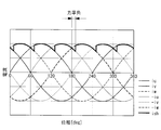
- FIG. 2 shows a duty waveform of a gate drive signal based on conventional one-pulse control.
- FIG. 2 shows the on-duty waveform of the gate drive signal applied to the switching elements of the U-phase and V-phase upper arms.
- the upper arm of the W phase (not shown) has a waveform that is 120 ° out of phase with the on-duty waveform of the V phase. Further, since the lower arm operates with the complement of the upper arm, the on-duty of the upper arm corresponds to the off-duty of the lower arm.
- the inductance of the coil 4 and the capacity of the smoothing capacitor 5 are set so that the resonance frequency becomes 9.589 [kHz], and the command value setting of the motor rotational speed is set to the resonance frequency of the low pass filter 9. It was set to 133 [rpm] which is 1/72 times of 589 [kHz].
- FIG. 3 is a diagram showing simulation results.
- the duty has a duty waveform as a basis of the gate drive signal applied to the switching element of the upper arm of the U-phase, V-phase and W-phase of the inverter 2, and the DC current Idc is smoothed in the DC bus 3b of N pole.
- the current flowing on the power supply side of the connection point Sa with the capacitor 5 the bus current Ish is the current flowing on the inverter side of the connection point Sa, and the motor current is each phase current output from the inverter 2 to the IPM motor 8.
- the DC current Idc and the bus current Ish are in resonance. In order to analyze this resonance state, fast Fourier transform (Fast Fourier Transform) was performed and frequency analysis was performed.
- Fast Fourier transform Fast Fourier transform
- FIG. 4A shows the frequency analysis result of the direct current Idc shown in FIG. 3, and FIG. 4B shows the frequency analysis result of the bus current Ish shown in FIG.
- the fundamental frequency fn is as the following equation (1).
- the fourth harmonic component of the fundamental frequency fn substantially coincides with the resonance frequency of 9.589 [kHz] of the low pass filter 7, and a particularly large ripple component is generated by resonating with the low pass filter 7.
- the duty waveform of the gate drive signal is to be gradually increased or decreased at a predetermined phase angle width at the rise and fall thereof.
- FIG. 5 exemplifies the waveform in the case where the duty is increased or decreased in a linear function at a predetermined phase angle width, it is possible to select any waveform at the time of increase and decrease. It is.
- an increase waveform and a decrease waveform may be used in which part of a sine wave is cut off.
- FIG. 7 exemplifies the case where the duty waveform at the rise time of the gate drive signal is linearly increased at a phase angle width of 20 [deg].
- the on-duty waveform in the conventional one pulse control is indicated by a broken line for comparison.
- 1 ⁇ 2 of the phase angle width is overlapped and defined as the phase angle ⁇ ⁇ .
- FIG. 8 (a) is a diagram schematically showing a bus current waveform when a rectangular wave voltage is applied to the inverter 2 in the conventional one-step control as shown in FIG. 2, and FIG. 8 (b) is FIG.
- FIG. 7 is a diagram schematically showing a bus current waveform when the overlapping phase angle ⁇ ⁇ is given as shown in FIG.
- FIG. 8 (b) by gradually changing the duty from 0 [%] to 100 [%] or from 100 [%] to 0 [%] with a certain phase width.
- the motor current between the two phases can be switched continuously. This makes it possible to reduce harmonic components of the bus current Ish.
- the inventors examined how much the harmonic can be reduced most effectively when the overlapping phase angle ⁇ ⁇ is given.
- the inventors paid attention to the power factor and examined the relationship between the power factor and the overlapping phase angle ⁇ ⁇ .
- the motor terminal voltage (U phase), the motor current (U phase), the bus current Ish, and the direct current Idc were simulated.
- the simulation results are shown in FIG. 9 to FIG.
- FIG. 9 shows the case of the leading power factor
- FIG. 10 shows the case of the power factor 1
- FIG. 11 shows the case of the delayed power factor.
- FIGS. 12 to 14 schematically show the relationship between the U-phase, V-phase and W-phase currents (positive and negative) and the bus current Ish at each power factor shown in FIGS. 9 to 11. .
- FIG. 12 shows the case of leading power factor
- FIG. 13 shows the case of power factor 1
- FIG. 14 shows the case of delayed power factor.
- the difference between the timing at which the negative motor current phase and the adjacent timing bus current Ish is switched become equal substantially becomes power factor angle by switching, gradually as the phase angle theta alpha overlapping this period It has been found that if the duty is changed, fluctuation of the bus current Ish can be suppressed and reduction of harmonic components can be expected.
- the motor voltage V is taken at an angle of ⁇ ⁇ ⁇ [rad] with respect to the direction of the induced voltage E, and the vector of the motor voltage V and the vector of the induced voltage E are connected by a straight line.
- the vector passing through the origin 0 orthogonal to this straight line becomes the vector of the current I if the resistance component is ignored, and hence the angle between the motor voltage V and the current I is the power factor angle ⁇ .
- FIG. 18 exemplifies the case where the magnitude of the motor voltage V and the magnitude of the induced voltage E are 1: 1. It can be understood from FIG. 18 that the power factor angle ⁇ can be changed by changing the magnitude of the motor voltage V and the magnitude of the induced voltage E or the angle ⁇ formed by the motor voltage V and the induced voltage E.
- the ratio of the magnitude of the vector of motor voltage V to the magnitude of the vector of induced voltage E is 1: 0.8, and the value of ⁇ is changed to 0, 0.1, 0.2, 0.3, respectively. It is the figure which showed the relationship of the overlap phase angle (theta) alpha at the time of making it, and the ripple contained in the direct current Idc.
- FIG. 16 assuming that the ratio of the vector magnitude of motor voltage V to the vector magnitude of induced voltage E is 1: 1
- FIG. 17 shows the vector magnitude of motor voltage V and the vector magnitude of induced voltage E.
- the relationship between the overlap phase angle ⁇ ⁇ and the ripple included in the direct current Idc when the ratio of length to height is 1: 1.2 is shown.
- ripple disortion current
- FIG. 19 is a graph showing the overlap phase angle [deg] on the horizontal axis and the ripple and voltage utilization factor on the vertical axis. As shown in FIG. 19, the voltage utilization factor decreases as the overlap phase angle [deg] increases, and the ripple current can be effectively reduced in the range where the overlap phase angle is about 10 [deg] or more. I understand.
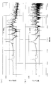
- FIG. 20 shows the duty waveforms of the upper arms of the U phase, the V phase and the W phase, the DC current Idc, the bus current Ish, and the motor current when the overlap phase angle is 10 [deg].
- 21 (a) shows the frequency analysis result of the direct current Idc shown in FIG. 20
- FIG. 21 (b) shows the frequency analysis result of the bus current Ish shown in FIG.
- FIG. 22 shows the duty waveforms of the upper arms of the U phase, the V phase and the W phase, the DC current Idc, the bus current Ish, and the motor current when the overlap phase angle is 30 [deg].
- FIG. 23 (a) shows the frequency analysis result of the direct current Idc shown in FIG. 22, and FIG. 23 (b) shows the frequency analysis result of the bus current Ish shown in FIG.
- the predetermined phase angle width in other words, the harmonics included in the direct current Idc by gradually changing the duty using the overlapping phase angle. It has been verified that the wave component can be reduced. Further, it has been found that it is preferable to set the overlapping phase angle ⁇ ⁇ according to the power factor angle ⁇ .
- the maximum value of the power factor angle in the state where the motor current is large is obtained in advance using the maximum motor rotational speed and the maximum motor torque that can be output, and the maximum value of this power factor angle is overlapped to obtain the phase angle ⁇ ⁇
- the duty waveform in one pulse control is generated using this overlapping phase angle ⁇ ⁇ .
- the maximum power factor angle ⁇ _max in the motor drive can be determined, for example, by the following procedure.
- the voltage equation of the IPM motor in the steady state is given by the following equation (2).
- R is a winding resistance [ ⁇ ]
- L d is a d-axis inductance [H]
- L q is a q-axis inductance [H]
- ⁇ d is an induced voltage coefficient [V / (rad / s) ]
- N is the pole pair number
- v d is d axis voltage [V]
- v q is q axis voltage [V]
- id is d axis current [A]
- iq is q axis current [A]
- ⁇ m is It is a rotational speed [rad / s].
- V max 2 v d 2 + v q 2 (4)
- V max is the inverter output voltage maximum value.
- the maximum load torque ⁇ max , the voltages v d_max and v q_max when operating at the maximum rotational speed ⁇ m_max , and the currents i d_max and i q_max are obtained by solving the above equations (2) to (4) simultaneously From these voltages v d — max and v q — max and currents i d — max and i q — max, the maximum power factor angle ⁇ max can be obtained by the following equation (5).
- ⁇ max tan -1 (v d_max / v q_max )-tan -1 ( id_max / i q_max ) (5)
- FIG. 24 is a block diagram showing a schematic configuration of a motor drive device according to the present embodiment.
- the same components as those of the motor drive device shown in FIG. 1 are designated by the same reference numerals, and the description thereof will be omitted.
- the inverter device 1 includes a current sensor 6 for detecting the bus current Ish flowing through the N pole DC bus 3b and a voltage sensor 9 for detecting the input DC voltage Vdc of the inverter 2.
- the direct current Ish detected by the current sensor 6 and the input DC voltage Vdc detected by the voltage sensor 9 are input to the inverter control device 10.
- the current sensor 6 is a shunt resistor.
- the current sensor 6 is provided on the negative electrode side of the DC power supply 3 in FIG. 24, it may be provided on the positive electrode side.
- the inverter control device 10 is, for example, an MPU (Micro Processing Unit), and includes a computer-readable recording medium on which a program for executing each process described below is recorded.
- the CPU executes the recording medium.
- the following processing is realized by reading the program recorded in the above into a main storage device such as a RAM and executing the program.
- Examples of the computer readable recording medium include a magnetic disk, a magneto-optical disk, a semiconductor memory, and the like.
- Inverter control device 10 generates gate drive signals S such that the rotational speed of IPM motor 8 matches the motor speed command given from the upper control device (not shown) for each phase, and these are each phase of inverter 2 To control the inverter 2 to supply the desired three-phase alternating current to the IPM motor 8.
- FIG. 24 shows functional blocks in which functions of the inverter control device 10 are expanded and shown.
- the inverter control device 10 mainly includes a vector control unit 11, a duty command calculation unit 12, a polar coordinate conversion unit 13, a duty calculation unit 14, and a gate drive signal generation unit 15.
- the vector control unit 11 calculates the d-axis voltage command v d * and the q-axis voltage command v q * based on known vector control, and outputs these values to the duty command calculation unit.
- Duty command calculation unit 12 the following (6) and (7), using the input DC voltage Vdc detected by the voltage sensor 9, * voltage command v d from the vector control unit 11, the v q *
- the d-axis duty duty d and the q-axis duty duty q are calculated respectively.
- duty d v d * / (Vdc / 2 1/2 ) (6)
- duty q v q * / (Vdc / 2 1/2 ) (7)
- the polar coordinate conversion unit 13 converts the d-axis duty duty d and the q-axis duty duty q into polar coordinates (fixed coordinates) by the following equations (8) and (9).
- FIG. 25 shows the relationship between polar coordinates and the d-axis and q-axis.
- the duty calculation unit 14 calculates the duty of the gate drive signal S of each phase from the angle ⁇ v of the polar coordinates obtained by the polar coordinate conversion unit 13 and the length
- the voltage utilization factor in the case where one pulse control is performed by setting the rate angle ⁇ max is obtained in advance and set to this value.
- the threshold Mx is set to, for example, 1.10. Ru.
- the duty waveform generated by the duty calculation unit 14 is output to the gate drive signal generation unit 15, and the gate drive signal S is generated based on the duty waveform.
- the gate drive signal S generated in this manner is applied to each switching element of the inverter 2, and on / off is controlled based on the gate drive signal S.
- a gate drive signal S such that the duty gradually increases or decreases at a predetermined phase angle width is generated and supplied to each switching element of inverter 2.
Landscapes
- Engineering & Computer Science (AREA)
- Power Engineering (AREA)
- Transportation (AREA)
- Mechanical Engineering (AREA)
- Life Sciences & Earth Sciences (AREA)
- Sustainable Development (AREA)
- Sustainable Energy (AREA)
- Control Of Motors That Do Not Use Commutators (AREA)
- Inverter Devices (AREA)
- Control Of Ac Motors In General (AREA)
Abstract
直流電源から電力供給を受けるモータ駆動装置において、1パルス制御の実行中に、直流電源に流れる電流に含まれるリップルを抑制することを目的とする。モータ駆動装置1は、電気角1周期の間に、各相に対応するスイッチング素子に対して正負1パルスの矩形波電圧をゲート駆動信号として印加する1パルス制御モードを有するインバータ制御装置(10)を備える。インバータ制御装置(10)は、1パルス制御モードを実行する場合に、矩形波電圧の立ち上がり時および立ち下がり時において、所定の位相角幅でデューティを徐々に増加または減少させる。
Description
本発明は、モータ駆動装置に係り、特に、直流電源から供給される直流電力を交流電力に変換してモータに供給するモータ駆動装置に関するものである。
従来、交流電源からの交流電力を整流器によって直流電力に変換し、更に、この直流電力をインバータにより三相交流電力に変換して交流モータに供給するモータ駆動装置が知られている(例えば、特許文献1参照)。
また、その一方で、直流電源とインバータとを接続し、直流電源からの直流電力を三相交流電力に変換して交流モータに供給するモータ駆動装置が知られている。このようなモータ駆動装置は、例えば、エンジンを搭載していない電気自動車等に搭載される車載空調機の圧縮機モータを駆動する場合等に採用される。
また、従来、インバータの電圧利用率を高める制御方法の一つとして、1パルス制御が知られている。1パルス制御は、電気角1周期の間に、各相に対応するスイッチング素子に対して正負1パルスの矩形波電圧をゲート駆動信号として印加する制御方法である(例えば、特許文献2参照)。
ところで、特許文献2に開示されているような1パルス制御を行う場合、直流母線には比較的大きな高調波電流が流れることとなる。しかしながら、交流電源から電力供給を受けるモータ駆動装置では、整流を行う必要があることから、比較的大きな容量(一般的には、1,000μFオーダー)の平滑コンデンサが設けられている。高調波は、この平滑コンデンサにより低減され、交流電源へ流れる電流に含まれるリップル(脈流)はそれほど大きくない。
しかしながら、直流電源から電力供給を受けるモータ駆動装置では、整流の必要がない。従って、コスト低減および装置の小型化の目的から、かなり小さな容量(一般的には、10μFから100μFオーダー)の平滑コンデンサが採用される。このため、1パルス制御によって発生した高調波成分を平滑コンデンサによって効果的に低減することができず、直流電源に流れる電流に比較的大きなリップルが含まれることとなる。そして、このリップルが直流電源と接続される周辺機器にノイズとして影響を及ぼすことが懸念されていた。
本発明は、直流電源から電力供給を受けるモータ駆動装置において、1パルス制御の実行中に、直流電源に流れる電流に含まれるリップルを抑制することのできるモータ駆動装置を提供する。
本発明の第1態様は、直流電源から直流母線を介して入力される直流電力を三相交流電力に変換してモータに出力するインバータと、電気角1周期の間に、各相に対応するスイッチング素子に対して正負1パルスの矩形波電圧をゲート駆動信号として印加する1パルス制御モードを有するインバータ制御手段とを備え、前記インバータ制御手段は、前記1パルス制御モードを実行する場合に、前記矩形波電圧の立ち上がり時および立ち下がり時において、所定の位相角幅でデューティを徐々に増加または減少させるモータ駆動装置である。
本態様によれば、電気角1周期の間に、各相に対応するスイッチング素子に対して正負1パルスの矩形波電圧をゲート駆動信号として印加する1パルス制御モードを実行する際に、矩形波電圧の立ち上がり時及び立下り時において所定の位相角幅でデューティを徐々に増加または減少させる。従って、インバータのスイッチング素子のオンオフ切替時に伴い発生する電圧の変動量を低減させることができる。これにより、直流電源に流れる電流に含まれるリップルを低減させることが可能となる。
上記モータ駆動装置において、前記所定の位相角幅は、力率角に応じて設定されることが好ましい。
発明者らは、力率角が直流母線を流れる電流に含まれる高調波成分に関係していることを新たな知見として取得し、力率角に応じて所定の位相角幅を設定することとした。これにより、直流電源に流れる電流に含まれるリップルを効果的に低減させることが可能となる。
上記モータ駆動装置において、前記所定の位相角幅は、最大モータ回転速度及び最大モータトルクを用いて推定される力率角の最大値の2倍以上の値に設定されることが好ましい。
このような構成によれば、例えば、最大モータ回転速度及び最大モータトルクを用いて力率角の最大値がシミュレーションによって予め推定され、この力率角の最大値の2倍以上に所定の位相角幅が設定される。このように、所定の位相角幅を力率角の最大値の2倍以上に設定することで、力率角が最も大きな運転領域であっても直流電源に流れる電流に含まれる高調波成分(リップル)を効果的に低減させることができる。換言すると、1パルス制御中においては、力率角の変化の全域において直流電源に流れる電流に含まれる高調波成分を低減させることができる。
本発明によれば、1パルス制御の実行中において、直流電源に流れる電流に含まれるリップルを抑制することができるという効果を奏する。
以下、本発明の一実施形態に係るモータ駆動装置について、図面を参照して説明する。
まず、本実施形態に係るモータ駆動装置について説明する前に、直流電源とインバータとを接続する直流母線に発生するリップルについて検討するために行ったシミュレーションについて説明する。
まず、本実施形態に係るモータ駆動装置について説明する前に、直流電源とインバータとを接続する直流母線に発生するリップルについて検討するために行ったシミュレーションについて説明する。
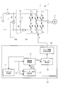
図1は、直流電源に接続されるモータ駆動装置の一般的な構成を概略的に示した回路図である。図1において、インバータ2は、P極およびN極の直流母線3a、3bによって直流電源3と接続されている。P極の直流母線3aには、コイル4が接続されている。P極の直流母線3aとN極の直流母線3bとの間には、平滑コンデンサ5が接続されている。コイル4及び平滑コンデンサ5により、ローパスフィルタ7が形成されている。
インバータ2は各相に対応して設けられた上アームのスイッチング素子S1u、S1v、S1wと下アームのスイッチング素子S2u、S2v、S2wとを備えており、これらのスイッチング素子が図示しないインバータ制御装置により制御されることにより、直流電力からIPMモータ(Interior Permanent Magnet Motor)8に供給される3相交流電力が生成される。
このようなモータ駆動装置において、従来の1パルス制御に基づく矩形波電圧をゲート駆動信号としてインバータ2の各スイッチング素子に与え、そのときにN極の直流母線3bに流れる電流をシミュレーションにより得た。
図2に、従来の1パルス制御に基づくゲート駆動信号のデューティ波形を示す。図2では、U相、V相の上アームのスイッチング素子に与えるゲート駆動信号のオンデューティ波形を示している。図示しないW相の上アームについては、V相のオンデューティ波形に対して位相が120°ずれた波形となる。また、下アームは、上アームの相補で動作させるため、上アームのオンデューティが下アームのオフデューティに相当する。
図2に、従来の1パルス制御に基づくゲート駆動信号のデューティ波形を示す。図2では、U相、V相の上アームのスイッチング素子に与えるゲート駆動信号のオンデューティ波形を示している。図示しないW相の上アームについては、V相のオンデューティ波形に対して位相が120°ずれた波形となる。また、下アームは、上アームの相補で動作させるため、上アームのオンデューティが下アームのオフデューティに相当する。
また、本シミュレーションにおいては、コイル4のインダクタンスと平滑コンデンサ5の容量を共振周波数が9.589[kHz]となるように設定し、モータ回転数の指令値設定をローパスフィルタ7の共振周波数9.589[kHz]の1/72倍である133[rpm]に設定した。
図3は、シミュレーション結果を示した図である。図3において、デューティは、インバータ2のU相、V相、W相の上アームのスイッチング素子に与えられるゲート駆動信号の基となるデューティ波形、直流電流Idcは、N極の直流母線3bにおいて平滑コンデンサ5との接続点Saよりも電源側を流れる電流、バス電流Ishは接続点Saよりもインバータ側を流れる電流、モータ電流はインバータ2からIPMモータ8に出力される各相電流である。
図3から直流電流Idc及びバス電流Ishが共振しているのがわかる。この共振状態を分析するため、高速フーリエ変換(Fast Fourier Transform)を行い、周波数分析を行った。
図3から直流電流Idc及びバス電流Ishが共振しているのがわかる。この共振状態を分析するため、高速フーリエ変換(Fast Fourier Transform)を行い、周波数分析を行った。
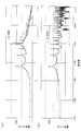
図4(a)は、図3に示した直流電流Idcの周波数分析結果、図4(b)は図3に示したバス電流Ishの周波数分析結果である。図4から直流電流Idcにおいて、基本波周波数fnのn次高調波成分が発生していることがわかり、更に、4次高調波成分が特に大きな値を示していることがわかった。ここで、基本周波数fnは、以下の(1)式の通りである。
fn=回転数×極対数×a=133[rps]×3×6=2.394[kHz] (1)
上記(1)式において、aはモータ1周期のうちでゲート駆動信号を変化させる回数であり、本実施形態では、電気角60[deg]毎にパターンを変化させていることから、a=6としている。
ここで、基本周波数fnの4次高調波成分は、ローパスフィルタ7の共振周波数9.589[kHz]と略一致しており、ローパスフィルタ7と共振することで特に大きなリップル成分が発生していることが分析により判明した。
ここで、基本周波数fnの4次高調波成分は、ローパスフィルタ7の共振周波数9.589[kHz]と略一致しており、ローパスフィルタ7と共振することで特に大きなリップル成分が発生していることが分析により判明した。
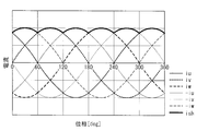
上記のような分析結果から、直流電流Idc及びバス電流Ishに生じる高調波成分を低減するために、本実施形態におけるモータ駆動装置では、図2に示したように、従来はステップ関数的に与えていたゲート駆動信号のデューティ波形を、図5に示すように、その立ち上がりおよび立下りにおいて、所定の位相角幅で徐々に増加または減少させることとした。なお、図5では、所定の位相角幅においてデューティを1次関数的に増加または減少させた場合の波形を例示しているが、増加時および減少時の波形については任意に選定することが可能である。例えば、図6に示すように、正弦波の一部を切り取るような増加波形および減少波形としてもよい。
図7は、ゲート駆動信号の立ち上がり時におけるデューティ波形を20[deg]の位相角幅で一次関数的に増加させた場合を例示している。図7において、従来の1パルス制御におけるオンデューティ波形を比較のために破線で示している。また、本実施形態においては、位相角幅の1/2を重ね位相角θαと定義する。
図5から図7に一例を示したように、デューティ波形において重ね位相角θαを持たせることで、図8(b)に示すように、バス電流Ishの波形を変化させることが可能となり、バス電流Ishに含まれる高調波成分を低減させることが可能となる。
図8(a)は、図2に示したような従来の1ステップ制御における矩形波電圧をインバータ2に与えた時のバス電流波形を模式的に示した図、図8(b)は図5から図7に示すように重ね位相角θαを持たせた場合のバス電流波形を模式的に示した図である。
図8(b)からわかるように、ある一定の位相幅を持たせて徐々にデューティを0[%]から100[%]に、または、100[%]から0[%]に変化させることにより、2相間のモータ電流を連続的に切り替えることができる。これにより、バス電流Ishの高調波成分を低減させることが可能となる。また、デューティを徐々に変化させる所定の位相幅の期間においては、例えば、キャリア周波数でスイッチングを行うことにより、高調波のエネルギーを分散させることが可能となり、この効果としても、高調波の低減を図ることが可能となる。
図8(b)からわかるように、ある一定の位相幅を持たせて徐々にデューティを0[%]から100[%]に、または、100[%]から0[%]に変化させることにより、2相間のモータ電流を連続的に切り替えることができる。これにより、バス電流Ishの高調波成分を低減させることが可能となる。また、デューティを徐々に変化させる所定の位相幅の期間においては、例えば、キャリア周波数でスイッチングを行うことにより、高調波のエネルギーを分散させることが可能となり、この効果としても、高調波の低減を図ることが可能となる。
次に、発明者らは、どの程度の重ね位相角θαを持たせた場合に、最も効果的に高調波を低減することができるか検討を行った。ここで、発明者らは、力率に着目し、力率と重ね位相角θαとの関係について検討した。
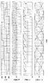
まず、デューティをステップ関数的に与える従来の1パルス制御において、力率を1、進み力率(=0.94)、遅れ力率(=0.98)の3パターンに変化させ、それぞれの場合において、モータ端子電圧(U相)、モータ電流(U相)、バス電流Ish、直流電流Idcをシミュレーションした。シミュレーション結果を図9から図11に示す。図9は進み力率の場合、図10は力率1の場合、図11は遅れ力率の場合を示している。
図9~図11から、図10に示した力率1の場合は直流電流Idcに含まれるリップルは小さいが、図9及び図11に示した進み力率および遅れ力率の場合には、相対的に大きなリップルが直流電流Idcに発生していることがわかる。これは、図9~図11において、期間Aとして示した波形からもわかるように、力率が変わると、モータ電流からバス電流Ishとして切り出される位相(位置)が変わり、インバータ2の相が切り替わったときに大きな電流変化が生じるためである。バス電流Ishの変化が大きくなると、バス電流Ishに含まれる高調波成分が増え、直流電流Idcのリップルも大きくなるということがわかった。
図12~図14は、図9~図11に示した各力率のときのU相、V相、W相電流(正負)と、バス電流Ishとの関係を模式的に示した図である。図12は進み力率の場合、図13は力率1の場合、図14は遅れ力率の場合を示している。図12~図14からわかるように、スイッチングによりバス電流Ishが切り替わるタイミングと隣接する相の負のモータ電流が等しくなるタイミングの差がおおむね力率角となり、この期間を重ね位相角θαとして徐々にデューティを変化させれば、バス電流Ishの変動を抑制でき、高調波成分の低減が期待できることがわかった。
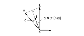
そこで、力率条件と重ね位相角θαとを変化させたときのリップルの変化についてシミュレーションを行った。シミュレーション結果を図15から図17に示す。ここで、シミュレーションに際して、力率角φは直接的に制御できないため、図18に示すように、モータ電圧Vの大きさと誘起電圧Eの大きさとの比率及びモータ電圧Vと誘起電圧Eとのなす角度α×π[rad]のαの値を変化させることにより、間接的に力率角φを変化させた。
すなわち、図18に示すように、誘起電圧Eの向きに対してα×π[rad]の角度でモータ電圧Vをとり、モータ電圧Vのベクトルと誘起電圧Eのベクトルを直線で結ぶ。この直線に直交し、原点0を通るベクトルが抵抗成分を無視すれば電流Iのベクトルとなり、よって、モータ電圧Vと電流Iとが成す角が力率角φとなる。図18は、モータ電圧Vの大きさと誘起電圧Eの大きさとが1:1の場合を例示している。図18から、モータ電圧Vの大きさと誘起電圧Eの大きさ、または、モータ電圧Vと誘起電圧Eとが成す角αを変化させれば、力率角φを変化させられることがわかる。
図15は、モータ電圧Vのベクトルの大きさと誘起電圧Eのベクトルの大きさとの比を1:0.8とし、αの値をそれぞれ0,0.1,0.2,0.3に変化させたときの重ね位相角θαと直流電流Idcに含まれるリップルとの関係を示した図である。同様に、図16はモータ電圧Vのベクトルの大きさと誘起電圧Eのベクトルの大きさとの比を1:1とした場合、図17はモータ電圧Vのベクトルの大きさと誘起電圧Eのベクトルの大きさとの比を1:1.2とした場合の重ね位相角θαと直流電流Idcに含まれるリップルとの関係をそれぞれ示している。
ここで、リップル(歪み電流)は、全ての次数高調波を対象として以下の式で計算した。

図15~図17に示されるように、リップルの低減に効果が現れる重ね位相角θαの値は、力率角φに応じて異なるものの、概ね10[deg]以上でリップル低減の効果が表れていることがわかった。
このように、図15~図17により、重ね位相角θαを持たせることにより、直流電流Idcに含まれる高調波成分を低減させることができることが検証された。
このように、図15~図17により、重ね位相角θαを持たせることにより、直流電流Idcに含まれる高調波成分を低減させることができることが検証された。
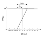
次に、ある力率角φにおける重ね位相角θα、リップル、及び電圧利用率の関係を分析した。図19は、横軸に重ね位相角[deg]、縦軸にリップル及び電圧利用率を示したグラフを示した図である。図19に示すように、重ね位相角[deg]が大きくなるほど電圧利用率が低下し、また、重ね位相角が約10[deg]以上の範囲において、リップル電流が効果的に低減できていることがわかる。
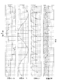
また、図20に重ね位相角を10[deg]としたときのU相、V相、W相の上アームのデューティ波形、直流電流Idc、バス電流Ish、およびモータ電流を示す。図21(a)に図20に示した直流電流Idcの周波数分析結果を、図21(b)に図20に示したバス電流Ishの周波数分析結果を示す。図22に重ね位相角を30[deg]としたときのU相、V相、W相の上アームのデューティ波形、直流電流Idc、バス電流Ish、およびモータ電流を示す。図23(a)に図22に示した直流電流Idcの周波数分析結果を、図23(b)に図22に示したバス電流Ishの周波数分析結果を示す。
図20~図23からわかるように、重ね位相角θαを持たせた場合には、基本波成分fnのn次高調波成分だけでなく、キャリア周波数fcに由来する高調波に対してもエネルギーが分散され、高調波成分が減少していることがわかった。
また、図4では顕著に表れていたローパスフィルタ7(図1参照)に由来する基本波成分の4次高調波成分についても、図21及び図23では、他の周波数成分の信号レベルと同等程度になっていることがわかった。
また、図4では顕著に表れていたローパスフィルタ7(図1参照)に由来する基本波成分の4次高調波成分についても、図21及び図23では、他の周波数成分の信号レベルと同等程度になっていることがわかった。
以上の分析結果から1パルス制御におけるデューティ波形の立ち上がり及び立ち下がり時において、所定の位相角幅、換言すると、重ね位相角を用いて徐々にデューティを変化させることにより、直流電流Idcに含まれる高調波成分を低減させることができることが検証された。また、この重ね位相角θαについては、力率角φに応じて設定することが好ましいことがわかった。
本実施形態では、予め出力可能な最大モータ回転数や最大モータトルクなどを用いてモータ電流が大きい状態での力率角の最大値を求め、この力率角の最大値を重ね位相角θαとして設定し、この重ね位相角θαを用いて1パルス制御におけるデューティ波形を生成することとした。
まず、モータ駆動装置における最大力率角φ_maxは、例えば、以下の手順によって求めることができる。
まず、定常状態でのIPMモータの電圧方程式は以下の(2)式で与えられる。
まず、定常状態でのIPMモータの電圧方程式は以下の(2)式で与えられる。

上記(2)式において、Rは巻線抵抗[Ω]、Ldはd軸インダクタンス[H]、Lqはq軸インダクタンス[H]、Λdは誘起電圧係数[V/(rad/s)]、nは極対数、vdはd軸電圧[V]、vqはq軸電圧[V]、idはd軸電流[A]、iqはq軸電流[A]、ωmは回転速度[rad/s]である。
このとき、モータの発生トルクτは、以下の(3)式で表わされる。
τ=nΛdiq+n(Ld-Lq)idiq (3)
インバータから出力できる最大電圧Vmaxで動作している場合を想定するとモータ電圧は以下の(4)式で表わされる。
Vmax
2=vd
2+vq
2 (4)
(4)式において、Vmaxはインバータ出力電圧最大値である。
最大負荷トルクτmax、最大回転速度ωm_maxで動作しているときの電圧vd_max、vq_max、電流id_max、iq_maxは上記(2)~(4)式を連立して解くことで得ることができ、これらの電圧vd_max、vq_max、電流id_max、iq_maxから最大力率角φmaxは以下の(5)式により求めることができる。
最大負荷トルクτmax、最大回転速度ωm_maxで動作しているときの電圧vd_max、vq_max、電流id_max、iq_maxは上記(2)~(4)式を連立して解くことで得ることができ、これらの電圧vd_max、vq_max、電流id_max、iq_maxから最大力率角φmaxは以下の(5)式により求めることができる。
φmax=tan-1(vd_max/vq_max)-tan-1(id_max/iq_max)(5)
次に、本発明の一実施形態に係るモータ駆動装置の構成について説明する。
図24は本実施形態に係るモータ駆動装置の概略構成を示したブロック図である。図24において、図1に示したモータ駆動装置と同一の構成については、同一の符号を付し、説明を省略する。図24に示すように、インバータ装置1は、N極の直流母線3bに流れるバス電流Ishを検出するための電流センサ6及びインバータ2の入力直流電圧Vdcを検出する電圧センサ9を備えている。
図24は本実施形態に係るモータ駆動装置の概略構成を示したブロック図である。図24において、図1に示したモータ駆動装置と同一の構成については、同一の符号を付し、説明を省略する。図24に示すように、インバータ装置1は、N極の直流母線3bに流れるバス電流Ishを検出するための電流センサ6及びインバータ2の入力直流電圧Vdcを検出する電圧センサ9を備えている。
電流センサ6により検出された直流電流Ish及び電圧センサ9により検出された入力直流電圧Vdcはインバータ制御装置10に入力される。ここで、電流センサ6の一例としては、シャント抵抗が挙げられる。なお、図24では、電流センサ6を直流電源3の負極側に設けているが、正極側に設けることとしてもよい。
インバータ制御装置10は、例えば、MPU(Micro Processing Unit)であり、以下に記載する各処理を実行するためのプログラムが記録されたコンピュータ読み取り可能な記録媒体を有しており、CPUがこの記録媒体に記録されたプログラムをRAM等の主記憶装置に読み出して実行することにより、以下の各処理が実現される。コンピュータ読み取り可能な記録媒体としては、例えば、磁気ディスク、光磁気ディスク、半導体メモリ等が挙げられる。
インバータ制御装置10は、IPMモータ8の回転速度が上位の制御装置(図示略)から与えられるモータ速度指令に一致させるようなゲート駆動信号Sを相毎に生成し、これらをインバータ2の各相に対応するスイッチング素子に与えることでインバータ2を制御し、所望の3相交流電流をIPMモータ8に供給する。
図24では、インバータ制御装置10が備える機能を展開して示した機能ブロックを示している。インバータ制御装置10は、ベクトル制御部11、デューティ指令算出部12、極座標変換部13、デューティ算出部14、ゲート駆動信号生成部15を主な構成として備えている。
ベクトル制御部11は、公知のベクトル制御に基づき、d軸電圧指令vd
*、q軸電圧指令vq
*を算出し、これらの値をデューティ指令算出部に出力する。
デューティ指令算出部12は、以下の(6)、(7)式により、電圧センサ9によって検出された入力直流電圧Vdcを用いて、ベクトル制御部11からの電圧指令vd *、vq *からd軸デューティdutyd及びq軸デューティdutyqをそれぞれ算出する。
デューティ指令算出部12は、以下の(6)、(7)式により、電圧センサ9によって検出された入力直流電圧Vdcを用いて、ベクトル制御部11からの電圧指令vd *、vq *からd軸デューティdutyd及びq軸デューティdutyqをそれぞれ算出する。
dutyd=vd
*/(Vdc/21/2) (6)
dutyq=vq */(Vdc/21/2) (7)
dutyq=vq */(Vdc/21/2) (7)
極座標変換部13は、以下の(8)式、(9)式により、上記d軸デューティdutyd及びq軸デューティdutyqを極座標(固定座標)に変換する。ここで、図25に、極座標とd軸及びq軸との関係を示す。

デューティ算出部14は、極座標変換部13によって得られた極座標の角度θvと長さ|duty|から各相のゲート駆動信号Sのデューティを算出する。具体的には、デューティ算出部14は、極座標変換部13によって得られた|duty|から変調パターンを決める。
例えば、|duty|が1未満であれば通常の正弦波PWM制御によるPWM信号を出力し、|duty|が1以上所定の閾値Mx未満の場合にはPWM過変調制御によるPWM信号を出力し、|duty|がMx以上の場合には、本実施形態に係る1パルス制御、すなわち、デューティの立ち上がり時および立下り時において、予め設定されている位相角幅(2×重ね位相角θα)で徐々にデューティが変化するデューティ波形を生成する。
ここで、重ね位相角θαは予め上記(2)式~(5)式を用いて算出された最大力率角φmaxに設定されており、閾値Mxは、重ね位相角θα=最大力率角φmaxに設定して1パルス制御を行った場合の電圧利用率を予め得ておき、この値に設定されている。例えば、図19に示した例において、重ね位相角θαを10[deg]に設定した場合、電圧利用率は約1.10であり、よって、閾値Mxは、例えば、1.10に設定される。
ここで、重ね位相角θαは予め上記(2)式~(5)式を用いて算出された最大力率角φmaxに設定されており、閾値Mxは、重ね位相角θα=最大力率角φmaxに設定して1パルス制御を行った場合の電圧利用率を予め得ておき、この値に設定されている。例えば、図19に示した例において、重ね位相角θαを10[deg]に設定した場合、電圧利用率は約1.10であり、よって、閾値Mxは、例えば、1.10に設定される。
デューティ算出部14によって生成されたデューティ波形は、ゲート駆動信号生成部15に出力され、このデューティ波形に基づいてゲート駆動信号Sが生成される。なお、このとき、デューティが徐々に変化する位相角幅(2θα)の期間においては、例えば、キャリア周波数でスイッチングを行うように設定される。このようにして生成されたゲート駆動信号Sは、インバータ2の各スイッチング素子に与えられ、このゲート駆動信号Sに基づいてオンオフが制御される。
以上説明してきたように、本実施形態に係るモータ駆動装置1によれば、|duty|の値が予め設定されているMx以上の場合には、1パルス制御における矩形波電圧の立ち上がり及び立下り時に、所定の位相角幅でデューティが徐々に増加または減少するようなゲート駆動信号Sが生成されて、インバータ2の各スイッチング素子に与えられる。これにより、1パルス制御中におけるバス電流Ish及び直流電流Idcに含まれるリップル(高調波成分)を低減させることができる。
1 モータ駆動装置
2 インバータ
3 直流電源
3a P極の直流母線
3b N極の直流母線
4 コイル
5 平滑コンデンサ
7 ローパスフィルタ
8 IPMモータ
10 インバータ制御装置
11 ベクトル制御部
12 デューティ指令算出部
13 極座標変換部
14 デューティ算出部
15 ゲート駆動信号生成部
2 インバータ
3 直流電源
3a P極の直流母線
3b N極の直流母線
4 コイル
5 平滑コンデンサ
7 ローパスフィルタ
8 IPMモータ
10 インバータ制御装置
11 ベクトル制御部
12 デューティ指令算出部
13 極座標変換部
14 デューティ算出部
15 ゲート駆動信号生成部
Claims (3)
- 直流電源から直流母線を介して入力される直流電力を三相交流電力に変換してモータに出力するインバータと、
電気角1周期の間に、各相に対応するスイッチング素子に対して正負1パルスの矩形波電圧をゲート駆動信号として印加する1パルス制御モードを有するインバータ制御手段と
を備え、
前記インバータ制御手段は、
前記1パルス制御モードを実行する場合に、前記矩形波電圧の立ち上がり時および立ち下がり時において、所定の位相角幅でデューティを徐々に増加または減少させるモータ駆動装置。 - 前記所定の位相角幅は、力率角に応じて設定される請求項1に記載のモータ駆動装置。
- 前記所定の位相角幅は、最大モータ回転速度及び最大モータトルクを用いて推定される力率角の最大値の2倍以上の値に設定されている請求項1または請求項2に記載のモータ駆動装置。
Priority Applications (3)
| Application Number | Priority Date | Filing Date | Title |
|---|---|---|---|
| EP12847735.3A EP2779433B8 (en) | 2011-11-10 | 2012-11-08 | Motor drive device |
| US14/344,528 US9450523B2 (en) | 2011-11-10 | 2012-11-08 | Motor drive apparatus |
| CN201280048245.0A CN103843246B (zh) | 2011-11-10 | 2012-11-08 | 电动机驱动装置 |
Applications Claiming Priority (2)
| Application Number | Priority Date | Filing Date | Title |
|---|---|---|---|
| JP2011-246652 | 2011-11-10 | ||
| JP2011246652A JP6138413B2 (ja) | 2011-11-10 | 2011-11-10 | モータ駆動装置 |
Publications (1)
| Publication Number | Publication Date |
|---|---|
| WO2013069747A1 true WO2013069747A1 (ja) | 2013-05-16 |
Family
ID=48290117
Family Applications (1)
| Application Number | Title | Priority Date | Filing Date |
|---|---|---|---|
| PCT/JP2012/079030 Ceased WO2013069747A1 (ja) | 2011-11-10 | 2012-11-08 | モータ駆動装置 |
Country Status (5)
| Country | Link |
|---|---|
| US (1) | US9450523B2 (ja) |
| EP (1) | EP2779433B8 (ja) |
| JP (1) | JP6138413B2 (ja) |
| CN (1) | CN103843246B (ja) |
| WO (1) | WO2013069747A1 (ja) |
Families Citing this family (11)
| Publication number | Priority date | Publication date | Assignee | Title |
|---|---|---|---|---|
| JP6236341B2 (ja) * | 2014-03-25 | 2017-11-22 | アスモ株式会社 | モータ駆動装置 |
| US9419553B2 (en) * | 2014-07-25 | 2016-08-16 | Denso Corporation | Apparatus for controlling rotary machine |
| JP6583109B2 (ja) * | 2016-04-12 | 2019-10-02 | 株式会社デンソー | 交流電動機の制御装置 |
| US10291147B2 (en) | 2016-09-29 | 2019-05-14 | Ge Global Sourcing Llc | Current reduction system for inverters connected to a common bus |
| JP6711326B2 (ja) * | 2017-07-14 | 2020-06-17 | 株式会社デンソー | 回転電機の駆動システム |
| KR102523253B1 (ko) * | 2018-03-21 | 2023-04-20 | 현대자동차주식회사 | 전기 자동차의 충전 장치 |
| CN109379018A (zh) * | 2018-11-12 | 2019-02-22 | 华润微电子(重庆)有限公司 | 一种三相交流电机的变频控制电路及控制方法 |
| JP7299723B2 (ja) * | 2019-03-14 | 2023-06-28 | 三菱重工サーマルシステムズ株式会社 | 制御装置、電動コンプレッサおよび制御方法 |
| JP7408345B2 (ja) * | 2019-10-24 | 2024-01-05 | 三菱重工サーマルシステムズ株式会社 | 制御装置、電動圧縮機、制御方法、プログラム |
| GB2632205A (en) * | 2022-05-23 | 2025-01-29 | Mitsubishi Electric Corp | Motor drive device, refrigeration cycle device, and refrigeration cycle system |
| EP4604378A1 (en) * | 2024-02-13 | 2025-08-20 | Thermo King LLC | Methods of controlling a supply of electrical power and electrical systems |
Citations (8)
| Publication number | Priority date | Publication date | Assignee | Title |
|---|---|---|---|---|
| JPH04325894A (ja) * | 1991-04-25 | 1992-11-16 | Toshiba Corp | 同期電動機の制御装置 |
| JPH05161364A (ja) | 1991-12-03 | 1993-06-25 | Toshiba Corp | インバータ装置 |
| JP2003018878A (ja) * | 2001-06-28 | 2003-01-17 | Mitsubishi Electric Corp | モータ駆動装置及び送風機 |
| JP2005027390A (ja) * | 2003-06-30 | 2005-01-27 | Mitsuba Corp | ブラシレスモータの駆動装置 |
| JP2005137200A (ja) | 1993-12-17 | 2005-05-26 | Hitachi Ltd | 電気車の制御装置 |
| JP2007028891A (ja) * | 2005-07-15 | 2007-02-01 | Taida Electronic Ind Co Ltd | モーター制御方法とその装置 |
| WO2010104008A1 (ja) * | 2009-03-09 | 2010-09-16 | 株式会社明電舎 | 電流形インバータ装置 |
| JP2011211832A (ja) * | 2010-03-30 | 2011-10-20 | Renesas Electronics Corp | ブラシレスdcモータの駆動装置および駆動方法 |
Family Cites Families (12)
| Publication number | Priority date | Publication date | Assignee | Title |
|---|---|---|---|---|
| JPH0667262B2 (ja) * | 1986-10-03 | 1994-08-24 | 三菱電機株式会社 | 交流電動機の制御装置 |
| JPH01189566A (ja) * | 1988-01-25 | 1989-07-28 | Mitsubishi Electric Corp | 直流電流検出器 |
| JP2765315B2 (ja) | 1991-11-18 | 1998-06-11 | 株式会社日立製作所 | 電力変換装置及びこれを利用した電気車の制御装置 |
| JP2851557B2 (ja) * | 1995-03-14 | 1999-01-27 | 日本サーボ株式会社 | ステッピングモータ駆動制御装置 |
| US5561595A (en) * | 1995-03-24 | 1996-10-01 | Magl Power Inc. | Power inverter with input line conditioning |
| JP2003169490A (ja) * | 2001-12-03 | 2003-06-13 | Mitsubishi Heavy Ind Ltd | 電動機制御システム、電動機制御装置、及び電動機駆動用インバータ制御方法 |
| JP4674525B2 (ja) * | 2005-10-13 | 2011-04-20 | 株式会社デンソー | 磁極位置推定方法及びモータ制御装置 |
| US7888905B2 (en) * | 2008-01-11 | 2011-02-15 | GM Global Technology Operations LLC | Method and system for controlling a power inverter in electric drives |
| JP5473289B2 (ja) | 2008-10-07 | 2014-04-16 | 三菱重工業株式会社 | 永久磁石型同期モータの制御装置及び制御方法 |
| BRPI1006833B1 (pt) | 2009-01-14 | 2020-10-20 | Panasonic Corporation | dispositivo de acionamento de motor |
| JP5195444B2 (ja) * | 2009-01-14 | 2013-05-08 | パナソニック株式会社 | ブラシレスdcモータの駆動装置並びにこれを用いた冷蔵庫及び空気調和機 |
| CN102474192B (zh) * | 2009-08-26 | 2014-09-10 | 大金工业株式会社 | 功率转换装置及其控制方法 |
-
2011
- 2011-11-10 JP JP2011246652A patent/JP6138413B2/ja active Active
-
2012
- 2012-11-08 EP EP12847735.3A patent/EP2779433B8/en active Active
- 2012-11-08 CN CN201280048245.0A patent/CN103843246B/zh active Active
- 2012-11-08 US US14/344,528 patent/US9450523B2/en active Active
- 2012-11-08 WO PCT/JP2012/079030 patent/WO2013069747A1/ja not_active Ceased
Patent Citations (8)
| Publication number | Priority date | Publication date | Assignee | Title |
|---|---|---|---|---|
| JPH04325894A (ja) * | 1991-04-25 | 1992-11-16 | Toshiba Corp | 同期電動機の制御装置 |
| JPH05161364A (ja) | 1991-12-03 | 1993-06-25 | Toshiba Corp | インバータ装置 |
| JP2005137200A (ja) | 1993-12-17 | 2005-05-26 | Hitachi Ltd | 電気車の制御装置 |
| JP2003018878A (ja) * | 2001-06-28 | 2003-01-17 | Mitsubishi Electric Corp | モータ駆動装置及び送風機 |
| JP2005027390A (ja) * | 2003-06-30 | 2005-01-27 | Mitsuba Corp | ブラシレスモータの駆動装置 |
| JP2007028891A (ja) * | 2005-07-15 | 2007-02-01 | Taida Electronic Ind Co Ltd | モーター制御方法とその装置 |
| WO2010104008A1 (ja) * | 2009-03-09 | 2010-09-16 | 株式会社明電舎 | 電流形インバータ装置 |
| JP2011211832A (ja) * | 2010-03-30 | 2011-10-20 | Renesas Electronics Corp | ブラシレスdcモータの駆動装置および駆動方法 |
Also Published As
| Publication number | Publication date |
|---|---|
| EP2779433A4 (en) | 2016-08-10 |
| JP2013106375A (ja) | 2013-05-30 |
| US20140340012A1 (en) | 2014-11-20 |
| EP2779433B1 (en) | 2018-07-25 |
| CN103843246A (zh) | 2014-06-04 |
| CN103843246B (zh) | 2017-06-20 |
| US9450523B2 (en) | 2016-09-20 |
| JP6138413B2 (ja) | 2017-05-31 |
| EP2779433B8 (en) | 2018-09-05 |
| EP2779433A1 (en) | 2014-09-17 |
Similar Documents
| Publication | Publication Date | Title |
|---|---|---|
| JP6138413B2 (ja) | モータ駆動装置 | |
| JP6555186B2 (ja) | 交流電動機の制御装置 | |
| CN110235357B (zh) | 逆变器控制装置 | |
| JP2009291019A (ja) | 交流モータ用インバータの制御装置 | |
| JP5803559B2 (ja) | 回転電機制御装置 | |
| JP5434696B2 (ja) | 車両用発電機 | |
| JP5813934B2 (ja) | 電力変換装置 | |
| JP2009189203A (ja) | Eps用モータ駆動装置 | |
| JP6657418B2 (ja) | 電流整形による最適なトルクリプル低減 | |
| EP2523343A2 (en) | Apparatus and method for controlling rotary electric machine | |
| JP2017192197A (ja) | 交流電動機の制御装置 | |
| US20160352269A1 (en) | Apparatus for controlling rotary electric machine | |
| JP2016189648A (ja) | インバータの制御装置 | |
| CN108696230B (zh) | 驱动装置和驱动系统 | |
| CN114930714B (zh) | 交流旋转电机的控制装置及电动助力转向装置 | |
| JP2013090401A (ja) | 回転電機制御システム | |
| CN113826317B (zh) | 旋转电机的控制装置 | |
| JP5196269B2 (ja) | 電動機の制御装置 | |
| JP2009273302A (ja) | 電動モータの制御装置 | |
| JP2012244740A (ja) | 駆動装置 | |
| JP2014068417A (ja) | インバータ制御装置 | |
| JP7067522B2 (ja) | インバータ装置 | |
| JP7073799B2 (ja) | モータ制御方法、及び、モータ制御装置 | |
| JP7767934B2 (ja) | 電動機の制御方法、及び電動機の制御装置 | |
| JP6221824B2 (ja) | 電力変換器の制御装置 |
Legal Events
| Date | Code | Title | Description |
|---|---|---|---|
| 121 | Ep: the epo has been informed by wipo that ep was designated in this application |
Ref document number: 12847735 Country of ref document: EP Kind code of ref document: A1 |
|
| DPE1 | Request for preliminary examination filed after expiration of 19th month from priority date (pct application filed from 20040101) | ||
| WWE | Wipo information: entry into national phase |
Ref document number: 14344528 Country of ref document: US |
|
| WWE | Wipo information: entry into national phase |
Ref document number: 2012847735 Country of ref document: EP |
|
| NENP | Non-entry into the national phase |
Ref country code: DE |