WO2013072981A1 - 撮像装置、制御装置、制御方法、及びプログラム - Google Patents
撮像装置、制御装置、制御方法、及びプログラム Download PDFInfo
- Publication number
- WO2013072981A1 WO2013072981A1 PCT/JP2011/076149 JP2011076149W WO2013072981A1 WO 2013072981 A1 WO2013072981 A1 WO 2013072981A1 JP 2011076149 W JP2011076149 W JP 2011076149W WO 2013072981 A1 WO2013072981 A1 WO 2013072981A1
- Authority
- WO
- WIPO (PCT)
- Prior art keywords
- instruction
- imaging
- control
- command
- image
- Prior art date
- Legal status (The legal status is an assumption and is not a legal conclusion. Google has not performed a legal analysis and makes no representation as to the accuracy of the status listed.)
- Ceased
Links
Images













Classifications
-
- H—ELECTRICITY
- H04—ELECTRIC COMMUNICATION TECHNIQUE
- H04N—PICTORIAL COMMUNICATION, e.g. TELEVISION
- H04N23/00—Cameras or camera modules comprising electronic image sensors; Control thereof
- H04N23/60—Control of cameras or camera modules
- H04N23/66—Remote control of cameras or camera parts, e.g. by remote control devices
- H04N23/661—Transmitting camera control signals through networks, e.g. control via the Internet
-
- H—ELECTRICITY
- H04—ELECTRIC COMMUNICATION TECHNIQUE
- H04N—PICTORIAL COMMUNICATION, e.g. TELEVISION
- H04N23/00—Cameras or camera modules comprising electronic image sensors; Control thereof
-
- H—ELECTRICITY
- H04—ELECTRIC COMMUNICATION TECHNIQUE
- H04N—PICTORIAL COMMUNICATION, e.g. TELEVISION
- H04N23/00—Cameras or camera modules comprising electronic image sensors; Control thereof
- H04N23/60—Control of cameras or camera modules
- H04N23/62—Control of parameters via user interfaces
-
- H—ELECTRICITY
- H04—ELECTRIC COMMUNICATION TECHNIQUE
- H04N—PICTORIAL COMMUNICATION, e.g. TELEVISION
- H04N23/00—Cameras or camera modules comprising electronic image sensors; Control thereof
- H04N23/60—Control of cameras or camera modules
- H04N23/695—Control of camera direction for changing a field of view, e.g. pan, tilt or based on tracking of objects
-
- H—ELECTRICITY
- H04—ELECTRIC COMMUNICATION TECHNIQUE
- H04N—PICTORIAL COMMUNICATION, e.g. TELEVISION
- H04N23/00—Cameras or camera modules comprising electronic image sensors; Control thereof
- H04N23/80—Camera processing pipelines; Components thereof
Definitions
- the present invention relates to an imaging apparatus capable of distributing a captured image to a terminal via a network, and more particularly to exclusion processing of a plurality of interfaces provided by the imaging apparatus to the terminal.
- an imaging apparatus that changes a direction in which imaging is performed by operating a camera platform.
- an imaging device that changes the direction in which the imaging device captures an image according to an instruction transmitted from a control device connected to the imaging device via a network. In such an imaging device, when the installation state of the imaging device is changed, the imaging device captures an image in different directions according to the same command before and after the change.
- the installation state is changed from a state in which the imaging device is erected and installed to a state in which the imaging device is inverted and installed on a ceiling or the like.
- the imaging device operates to direct the imaging direction downward. Do. In this manner, when the installation state of the imaging device is changed from upright to inverted, the vertical direction and the left and right direction in the imaging direction of the imaging device are reversed with respect to the same command.
- an imaging system that holds a plurality of control programs for changing the direction in which the imaging device captures an image, and switches the control program to be used according to the direction in which the imaging device is installed (for example, Patent Document 1) .
- This imaging system switches the coordinate system for representing the imaging direction by coordinates by switching the control program.
- the imaging device can turn the imaging direction in a certain direction with respect to a specific command regardless of the installation state.
- the control device receives and displays the captured image captured by the imaging device
- the change in the installation state of the imaging device also affects the direction of the captured image displayed in the control device. Therefore, it is desirable that the orientation of the captured image captured can also be changed.
- the installation state of the imaging device is changed from the upright state to the inverted state
- the top, bottom, left, and right of the captured image displayed on the control device is reversed. Therefore, by rotating the captured image captured in the upside-down state by 180 degrees and displaying it on the control device, the captured image in which the captured image captured in the upright state matches up, down, left, and right can be displayed.
- the interface for changing the direction of the captured image displayed on the control device and the interface for changing the coordinate system for controlling the imaging direction described above may be defined as separate commands.
- the vertical and horizontal directions in the captured image to be displayed The left and right orientations may not match.
- the instructions for changing the orientation of the captured image and the instructions for changing the orientation of the coordinate system one of the previously received instructions is processed, and the other instruction is unprocessed. The orientation does not match the orientation of the coordinate system.
- an imaging device by the present invention has the following composition, for example. That is, an imaging unit, a holding unit that holds a coordinate system used to indicate the imaging direction of the imaging unit, a first command to rotate a captured image captured by the imaging unit by a predetermined angle, and the storage unit Specified by the specific information, receiving means for receiving a second command to rotate the held coordinate system at the predetermined angle around the origin, specific information for specifying the imaging direction in the coordinate system, and A change control unit that performs control to change the imaging direction of the imaging unit in the imaging direction, and the first receiving unit receives one of the first instruction and the second instruction; And control means for performing control to execute the first instruction and the second instruction prior to reception of the other instruction out of the second instruction and the second instruction.
- an imaging device has, for example, the following configuration. That is, an imaging unit, a holding unit that holds a coordinate system used to represent an area in the imaging range of the imaging unit, and a first command to rotate a captured image extracted from the area on the imaging range by a predetermined angle A second command to rotate the coordinate system held by the holding means about the origin by the predetermined angle, and specific information for specifying, in the coordinate system, an area from which the captured image is cut out from the imaging range.
- Control means for performing control to execute the first command and the second command prior to the reception of the other command among the first command and the second command. With the door.
- control device has, for example, the following configuration. That is, a control device that controls an imaging apparatus having a holding unit that holds a coordinate system used to represent the imaging direction of the imaging unit, the identification unit specifying the imaging direction in the coordinate system, and the identification unit A first instruction to rotate the captured image captured by the imaging unit in the imaging direction specified by a predetermined angle, and a second instruction to rotate the coordinate system held by the storage unit about the origin at the predetermined angle Transmission control means for performing control to transmit the image pickup apparatus to the image pickup apparatus, and the transmission control means receives an instruction to transmit one of the first instruction and the second instruction to the image pickup apparatus; The first command and the second command are executed to the imaging device prior to the reception of the instruction to transmit the other command of the first command and the second command to the imaging device. And having a control means for performing control to.
- control device has, for example, the following configuration. That is, a control device for controlling an imaging apparatus having holding means for holding a coordinate system used to represent an area in an imaging range of the imaging means, the specifying means for specifying an area in the coordinate system; A first command to rotate a captured image of an area on the imaging range according to an area in the coordinate system specified by the means by a predetermined angle, and the predetermined coordinate system with the coordinate system held by the holding means as a center A transmission control unit configured to control transmission of a second instruction to rotate the angle to the imaging device, and the transmission control unit transmitting one of the first instruction and the second instruction to the imaging device When receiving the instruction to transmit, the first instruction to the imaging device is received prior to the reception of the instruction to transmit the other of the first instruction and the second instruction to the imaging device. And having a control means for performing control to execute the second instruction.
- the imaging device independently receives an instruction to change the direction of the captured image displayed on the control device and an instruction to change the direction of the coordinate system used to control the imaging direction of the imaging device. Even in this case, the imaging direction can be changed in the direction intended by the user.
- control device independently transmits an instruction to change the direction of the captured image displayed on the control device and an instruction to change the direction of the coordinate system used to control the imaging direction of the imaging device. Even in this case, the imaging direction can be changed in the direction intended by the user.
- FIG. 6 is a flowchart for explaining the operation of the imaging device according to the first embodiment.
- FIG. 6 is a flowchart for explaining the details of the operation of the imaging device according to the first embodiment;
- FIG. 6 is a flowchart for explaining the details of the operation of the imaging device according to the first embodiment;
- FIG. 6 is a flowchart for explaining the details of the operation of the imaging device according to the first embodiment;
- FIG. 6 is a flowchart for explaining the details of the operation of the imaging device according to the first embodiment; FIG. 6 is a flowchart for explaining the details of the operation of the imaging device according to the first embodiment;
- the figure for demonstrating the command which the imaging device which concerns on this invention receives The figure for demonstrating the command which the imaging device which concerns on this invention receives.
- the figure for demonstrating the command which the imaging device which concerns on this invention receives The figure for demonstrating the command which the imaging device which concerns on this invention receives.
- the figure for demonstrating the command which the imaging device which concerns on this invention receives.
- the figure for demonstrating the command which the imaging device which concerns on this invention receives.
- FIG. 7 is a flowchart for explaining the operation of the imaging device according to the second embodiment.
- FIG. 8 is a flowchart for explaining the details of the operation of the imaging device according to the second embodiment;
- FIG. 8 is a flowchart for explaining the details of the operation of the imaging device according to the second embodiment;
- FIG. 8 is a flowchart for explaining the details of the operation of the imaging device according to the second embodiment;
- FIG. 14 is a flowchart for explaining the operation of the control device according to the third embodiment.
- FIG. 14 is a flowchart for explaining the operation of the control device according to the third embodiment.
- Example 1 The configuration of the imaging system according to the present embodiment is shown in FIG. 1A.
- the imaging apparatus 1000 is connected to the client 3000 via the network 3020.
- the imaging apparatus 1000 distributes the captured image captured to the client 3000 via the network 3020.
- the network 3020 is composed of, for example, a plurality of routers, switches, cables and the like that satisfy a communication standard such as Ethernet (registered trademark).
- a communication standard such as Ethernet (registered trademark).
- the communication standard, the scale, and the configuration are not limited as long as communication between the imaging apparatus 1000 and the client 3000 can be performed.
- the network 3020 may be configured by the Internet, a wired LAN (Local Area Network), a wireless LAN (Wireless LAN), a WAN (Wide Area Network), or the like.
- the client 3000 transmits an instruction to the imaging apparatus 1000.
- the client 3000 transmits an instruction to change the imaging direction or the angle of view of the imaging apparatus 1000.
- the client 3000 transmits an instruction to rotate a coordinate system used to represent the position in the imaging range of the imaging device 1000 about the origin.
- the client 3000 further includes a display unit 3010 for displaying a captured image captured by the imaging device 1000, and transmits an instruction for rotating the captured image displayed on the display unit 3010 in the imaging device 1000.
- the imaging apparatus 1000 changes the imaging direction according to the command for changing the imaging direction received from the client 3000. Also, the imaging apparatus 1000 changes the angle of view in accordance with the command for changing the angle of view received from the client 3000.
- a drive mechanism for the imaging apparatus 1000 according to the present embodiment to change the imaging direction or the angle of view will be described using FIG. 1B.
- the pan drive mechanism 1101 changes the imaging direction of the imaging apparatus 1000 to the pan direction.
- the tilt drive mechanism 1102 changes the imaging direction of the imaging device 1000 to the tilt direction.
- the zoom mechanism 1103 changes the angle of view of the imaging device 1000.
- FIG. 2A An internal configuration of an imaging apparatus 1000 according to the present embodiment is shown in FIG. 2A.
- a control unit 1001 controls the entire imaging apparatus 1000.
- the control unit 1001 includes, for example, a CPU (Central Processing Unit), and executes a program stored in a memory 1002 described later. Alternatively, the control unit 1001 may perform control using hardware.
- CPU Central Processing Unit
- the memory 1002 is used as a data storage area, such as a program storage area executed by the control unit 1001, a work area in execution of a program, and a storage area of a captured image generated by an imaging unit 1003 described later.
- the memory 1002 also holds a coordinate system used to indicate the imaging direction of the imaging unit 1003 described later.
- the memory 1002 also displays information for indicating that an instruction is being executed when the control unit 1001 executes a specific instruction (automatic image direction change instruction or automatic coordinate direction change instruction) described later. Hold. For example, when a particular instruction is being executed, a flag managed in the memory 1002 can be set to indicate that the particular instruction is being executed.
- the imaging unit 1003 converts an analog signal acquired by photographing an object into digital data. Further, the imaging unit 1003 performs data compression processing by using adaptive discrete cosine transform (ADCT) or the like to generate a captured image of a captured image, and outputs the captured image to the memory 1002. After outputting the captured image to the memory 1002, the imaging unit 1003 transmits an image acquisition event to the control unit 1001.
- ADCT adaptive discrete cosine transform
- the communication unit 1004 receives from the client 3000 an imaging range change instruction shown in FIG. 5A, an image direction change instruction shown in FIG. 5B, and a coordinate direction change instruction shown in FIG. 5C.
- the communication unit 1004 transmits a reception event to the control unit 1001. Further, the communication unit 1004 transmits a response to the command in FIGS. 5A to 5C to the client.
- the communication unit 1004 transmits a normal response, which is a response for indicating that the received command is normally executed, or an error response, which is a response for indicating that the received command is not executed.
- Send to An example of a normal response is shown in FIG. 5E.
- an example of an error response is shown in FIG. 5F.
- the clock unit 1005 clocks the time elapsed after the imaging device 1000 receives the image direction change instruction or the coordinate direction change instruction.
- the timer unit 1005 transmits a time-out event to the control unit 1001 when a predetermined time has elapsed since the start of execution of a specific command (automatic image direction change instruction or automatic coordinate direction change instruction) described later.
- the imaging control unit 1006 controls the pan drive mechanism 1101, the tilt drive mechanism 1102, and the zoom mechanism 1103 according to an instruction of the control unit 1001. That is, when the communication unit 1004 receives an imaging range change command described later with reference to FIG. 5A from the client 3000, a reception event according to the command is transmitted to the control unit 1001. When the control unit 1001 receives a reception event, the control unit 1001 instructs the imaging control unit 1006 according to the content of the reception event.
- the imaging control unit 1006 that has received the control instruction performs control to drive the pan drive mechanism 1101, the tilt drive mechanism 1102, or the zoom mechanism 1103 according to the control instruction.
- the imaging control unit 1006 performs imaging in which the imaging unit 1003 captures an image at a position specified by coordinates designated by an imaging range change command described later with reference to FIG. 5A and the above-described coordinate system held in the memory 1002. Perform change control to change the direction. Thus, the imaging control unit 1006 performs control to change the imaging direction of the imaging unit 1003 in the imaging direction specified by the specific information.
- FIG. 2A The internal configuration of the imaging apparatus 1000 has been described above.
- the processing block illustrated in FIG. 2A is an example of a preferred embodiment of the imaging apparatus according to the present invention, and is not limited to this.
- Various modifications and changes are possible within the scope of the present invention, such as providing a voice input unit.
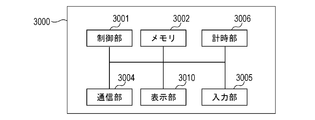
- the client 3000 is configured as a computer device connected to the network 3020.
- the control unit 3001 controls the entire client 3000.
- the control unit 3001 includes, for example, a CPU, and executes a program stored in a memory 3002 described later. Alternatively, the control unit 3001 may perform control using hardware.
- a memory 3002 is used as a program storage area executed by the control unit 3001, a work area during program execution, and a data storage area.
- the communication unit 3004 receives the captured image transmitted from the imaging apparatus 1000. Also, the communication unit 3004 transmits an instruction for controlling the imaging apparatus 1000.
- the input unit 3005 receives an input of an instruction from the user.
- the input unit 3005 can receive an input of a transmission instruction of various commands to the imaging device 1000 as an instruction from the user. Details of the instruction to the imaging apparatus 1000 will be described later with reference to FIGS. 5A to 5C.
- the input unit 3005 notifies the control unit 3001 that an instruction has been input.
- the control unit 3001 generates a command for the imaging device 1000 according to the instruction input to the input unit 3005, and performs transmission control for transmitting the generated command to the imaging device 1000 via the communication unit 3004.
- the input unit 3005 can also receive an input of a user's response to an inquiry message or the like to a user generated by the control unit 3001 executing a program stored in the memory 3002.
- the clock unit 3006 counts time that has elapsed since the image direction change instruction or the coordinate direction change instruction is transmitted to the imaging apparatus 1000.
- the display unit 3010 displays the captured image received by the communication unit 3004.
- the display unit 3010 can display a user inquiry message or the like generated by the control unit 3001 executing a program stored in the memory 3002.
- each instruction has a destination address indicating a destination to which the instruction is to be executed, and information on a transmission source address indicating a transmission source of the instruction.
- each instruction has information on the content and arguments of the instruction.
- the client 3000 changes the imaging range of the imaging apparatus 1000 according to the imaging range change command.
- the arguments of the imaging range change command are pan coordinates, tilt coordinates, and zoom coordinates in the coordinate system held in the memory 1002.
- the client 3000 and the imaging apparatus 1000 normalize the angle in the horizontal direction which can be imaged by the imaging apparatus 1000 from ⁇ 1.0 to +1.0.
- the pan direction of the imaging apparatus is represented by setting the value from -1.0 to +1.0 as pan coordinates.
- the client 3000 and the imaging apparatus 1000 normalize the angle in the vertical direction which can be imaged by the imaging apparatus 1000 from ⁇ 1.0 to +1.0.
- the tilt direction of the imaging device is represented using the value from ⁇ 1.0 to +1.0 as the tilt coordinate.
- the client 3000 and the imaging apparatus 1000 normalize the value for the range from the telephoto end to the wide end of the zoom from 0.0 to +1.0.
- the zoom value can be, for example, the value of zoom magnification or focal length.
- the zoom position of the imaging device is represented using the value from 0.0 to +1.0 as zoom coordinates.
- the client 3000 can specify absolute positions of pan coordinates, tilt coordinates, and zoom coordinates, and can arbitrarily change the imaging range of the imaging device 1000.
- the pan coordinates, tilt coordinates, or zoom coordinates held by the imaging range change command are specific information for specifying the imaging direction in the coordinate system held in the memory 1002.
- the imaging range change instruction need not have all the specific information of pan coordinates, tilt coordinates and zoom coordinates, and may have at least one specific information.
- the specific information is not limited to the one specifying the absolute position of pan coordinates, tilt coordinates, or zoom coordinates.
- the specific information may be information for representing the relative position of the imaging direction after movement with respect to the current imaging direction using a coordinate system.
- the specific information may be information on the movement direction and movement amount from the current position in the coordinate system.
- the imaging direction in the coordinate system can be specified. In this way, the user can use the client 3000 to instruct, for example, “move the imaging direction by +0.5 in the pan direction from the current position”.
- pan coordinates and tilt coordinates may be movement angles from a reference position (for example, a pan end, a tilt end, etc.) in the movable range of the pan drive mechanism 1101 or the tilt drive mechanism 1102.
- values of zoom magnification and focal length may be used as zoom coordinates.
- the client 3000 rotates the direction of the captured image distributed by the imaging apparatus 1000 by a predetermined angle (180 degrees in this embodiment).
- the imaging apparatus 1000 can, for example, rotate the direction of the captured image about the intersection of the diagonals of the captured image as a rotation center.
- the argument of the image direction change command is the image direction.
- OFF indicates the positive direction
- ON indicates the reverse direction.
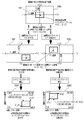
- the forward direction and the reverse direction of the captured image will be described with reference to FIG.
- a captured image 1070 is a captured image captured by the imaging unit 1003 of the imaging device 1000.
- the captured image 1071 shows a captured image distributed to the client 3000 when OFF (forward direction) is designated by the image direction change instruction shown in FIG. 5B.
- OFF forward direction
- the imaging apparatus 1000 transmits the captured image 1071 having the same image direction as the captured image 1070 to the client 3000.
- a captured image 1072 indicates a captured image delivered to the client 3000 when ON (inversion direction) is designated by the image direction change instruction shown in FIG. 5B.
- ON reverseversal direction
- the imaging apparatus 1000 transmits a captured image 1072 obtained by inverting the top and bottom and the left and right of the captured image 1070 to the client 3000.
- the imaging apparatus 1000 rotates the captured image captured by the imaging unit 1003 by a predetermined angle (in the case of the present embodiment, it is inverted 180 degrees). To the client 3000.
- the client 3000 can rotate the coordinate system held in the memory 1002 by a predetermined angle (180 degrees in the case of this embodiment) about the origin.
- the client 3000 can rotate the direction of the coordinate system at the same angle as the angle at which the captured image can be rotated by the above-described image orientation change instruction, by the coordinate orientation change instruction.
- the imaging device 1000 receives a coordinate direction change instruction, for example, the imaging device 1000 rotates the direction of the coordinate system with the origin of the coordinate system as the rotation center.
- the argument of the coordinate direction change instruction is a coordinate direction, OFF indicates a positive direction, and ON indicates a reverse direction. The positive direction and the reverse direction of the coordinate direction will be described with reference to FIG.
- coordinates 1080 indicate the imageable range of the imaging unit 1003 of the imaging device 1000.
- the range of pan coordinates and tilt coordinates is normalized from -1.0 to +1.0.
- the imaging range 1081 indicates the current imaging range of the imaging unit 1003 in the imaging available range, and pan coordinates, tilt coordinates, and zoom coordinates are respectively (0.0, 0.0, 1.0) at the coordinates 1080. Is set to).
- the coordinates 1082 and the coordinates 1083 are changed to pan coordinates, tilt coordinates and zoom coordinates of the imaging range 1081 to (0.3, -0.2, 1.0) by the imaging range change command shown in FIG. 5A, respectively. The case is shown.
- Coordinates 1082 indicate the imaging range when the coordinate direction in the positive direction is selected as an argument of the coordinate direction change instruction in FIG. 5C.
- the imaging device 1000 holds a coordinate system in the same direction as the coordinate 1080.
- coordinates 1083 indicate the imaging range 1081 when the coordinate direction of the reverse direction is selected as an argument of the coordinate direction change instruction of FIG. 5C.
- the imaging apparatus 1000 rotates the coordinate system of the coordinate 1080 (in this embodiment, 180 degrees reverse).
- the coordinates 1083 are such that the coordinate system indicating the image captureable range is rotated (reversed 180 degrees). Therefore, when the pan coordinates, tilt coordinates, and zoom coordinates of the imaging range 1081 are changed to (0.3, -0.2, 1.0) for the coordinates 1082 and the coordinates 1083, imaging is possible in the imaging available range The position of the imaging range 1081 captured by the apparatus 1000 is different.
- FIGS. 3 and 4A to 4D show a program for causing the control unit 1001 to execute the procedures shown in FIGS. 3 and 4A to 4D.
- the processor incorporated in the control unit 1001 of the imaging apparatus 1000 is a computer, and executes a program read from the memory 1002 incorporated in the imaging apparatus 1000.
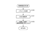
- the control unit 1001 waits for an event (S1100).
- the imaging apparatus 1000 determines that there is an event when an image acquisition, imaging range change instruction reception, image direction change instruction reception, coordinate direction change instruction reception, or automatic instruction timeout event occurs.
- the imaging apparatus 1000 executes the processing from step S1101 to step S1102 when an image acquisition event occurs.
- the image acquisition event is an event that occurs when the imaging device 1000 receives from the client 3000 an image acquisition request for acquiring a captured image captured by the imaging device 1000.
- control unit 1001 of the imaging apparatus 1000 performs distribution image creation processing (S1100). Details of the distribution image creation processing will be described later with reference to FIG. 4A.
- control unit 1001 When the distribution image creation processing is completed, the control unit 1001 performs transmission processing (S1102). In the transmission process, the control unit 1001 transmits the delivery image created in the delivery image creation process of step S1101 to the client 3000 requesting the video delivery from the imaging apparatus 1000 via the communication unit 1004. After performing the transmission process, the control unit 1001 returns to step S1100 and performs the process.
- control unit 1001 of the imaging apparatus 1000 receives the imaging range change command shown in FIG. 5A from the client 3000, the control unit 1001 performs imaging range change processing described later with reference to FIG. 4B (S1110).
- control unit 1001 When the control unit 1001 receives the image direction change instruction shown in FIG. 5B from the client 3000, the control unit 1001 performs an image direction change process described later with reference to FIG. 4C (S1120).
- control unit 1001 When the control unit 1001 receives the coordinate direction change instruction shown in FIG. 5C from the client 3000, the control unit 1001 performs coordinate direction change processing described later with reference to FIG. 4D (S1130).
- control unit 1001 may perform an automatic change processing time-out process described later when a predetermined time has elapsed after receiving the image direction change command or the coordinate direction change command.
- step S1110 When the process of step S1110, step S1120, step S1130, or step S1140 ends, the control unit 1001 returns to step S1100 and performs the process.
- the control unit 1001 refers to the memory 1002 and determines an image direction parameter (S1200).
- the image direction parameter is ON (Yes in S1200)
- the control unit 1001 reverses (180-degrees rotation) the captured image as shown in the captured image 1072 of FIG. Is overwritten, and the distribution image creation process is ended (S1201).
- the image direction parameter is OFF (in the case of No in S1200)
- the control unit 1001 does not perform the process and ends the distribution image creation process.
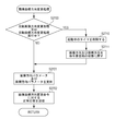
- the control unit 1001 refers to the memory 1002 and acquires coordinate direction parameters of the coordinate direction change instruction shown in FIG. 5C (S1300). Further, the control unit 1001 refers to the memory 1002 and acquires arguments (pan coordinates, tilt coordinates, zoom coordinates) of the imaging range change instruction shown in FIG. 5A (S1301).
- the control unit 1001 inputs the acquired coordinate direction parameter, pan coordinates, tilt coordinates, and zoom coordinates to the imaging control unit 1006 (S1302).
- the imaging control unit 1006 reverses the coordinate system and manipulates the imaging direction of the imaging unit 1003 as shown by the coordinates 1083 shown in FIG. 7.
- the imaging control unit 1006 manipulates the imaging direction of the imaging unit 1003 without inverting the coordinate system as in the coordinate 1082 shown in FIG. 7.
- the control unit 1001 ends the imaging range change processing.
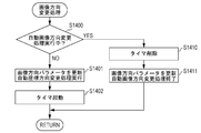
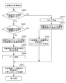
- the control unit 1001 refers to the memory 1002 to determine whether automatic image direction change processing is being performed (S1400).
- the automatic image direction change process is a process in which the control unit 1001 automatically executes the image direction change instruction regardless of the image direction change instruction received by the communication unit 1004.
- the automatic image direction change process is executed prior to the reception of the image direction change instruction when the communication unit 1004 receives the coordinate direction change instruction. Details of the automatic image direction change process will be described later with reference to FIG. 4D.
- the control unit 1001 reads an argument of the received image direction change instruction, and changes the image direction parameter on the memory 1002. Further, automatic coordinate direction change processing is performed (S1401).
- the automatic coordinate direction change process is a process in which the control unit 1001 automatically executes a coordinate direction change instruction regardless of the coordinate direction change instruction received by the communication unit 1004.
- the automatic coordinate direction change process is executed prior to the reception of the coordinate direction change instruction when the communication unit 1004 receives the image direction change instruction.
- control unit 1001 executes an instruction to automatically rotate the direction of the coordinate system by the same angle as the angle at which the captured image can be rotated by the image direction change instruction. That is, the control unit 1001 executes the received image direction change instruction and automatically executes the coordinate direction change instruction in step S1401.
- step S1401 When automatic coordinate direction change processing is started in step S1401, the control unit 1001 causes the memory 1002 to hold information indicating that automatic coordinate direction change processing is being performed (S1402).
- the information indicating that the automatic coordinate direction change process is being executed indicates, for example, that the automatic coordinate direction change process flag is set, indicating that the automatic coordinate direction change process is being executed, and that the flag is not executed when the flag is lowered.
- Can be The method of holding information indicating that the automatic coordinate direction changing process is being performed is not limited to this, and the control unit 1001 can determine whether the automatic coordinate direction changing process is being performed. Good.
- the control unit 1001 uses the clock unit 1005 to start a timer (S1403).
- This timer is a timer for continuing the state in which the coordinate direction parameter has been changed by the automatic coordinate direction changing process for a predetermined time after the start of the automatic coordinate direction changing process.
- the timer value of this timer may be preset by the user, and may be several hundreds of milliseconds to several seconds.
- the timer may be started when the communication unit 1004 receives an image direction change command, not when the automatic coordinate direction change process is started. In this way, it is possible to continue the state in which the coordinate direction parameter has been changed by the automatic coordinate direction changing process for a predetermined time after receiving the command.
- the control unit 1001 performs control to execute the image direction change instruction and the coordinate direction change instruction prior to the reception of the coordinate direction change instruction.
- the image direction change instruction is an instruction received by the communication unit 1004.
- the coordinate direction change instruction is an instruction executed by the control unit 1001 performing automatic coordinate direction change processing.
- the imaging apparatus 1000 can output the captured image (the captured image 1072 in FIG. 6) of the image direction after the change, and change the imaging range based on the coordinates after the change (coordinate 1083 in FIG. 7). . Therefore, the captured image can be output in a state where the image direction (forward direction / reverse direction) and the coordinate direction (forward direction / reverse direction) coincide with each other, and the imaging range can be changed. In this manner, only the image direction is changed (the captured image 1072 in FIG. 6) in the state (coordinate 1082 in FIG. 7) in which the coordinate direction is not changed. It is possible to prevent the image direction (forward direction / inversion direction) from becoming unmatched.
- the control unit 1001 deletes the timer (S1410).
- This timer is a timer activated in step S1503 described later.
- This timer is a timer for measuring how long a predetermined time for continuing the state in which the image direction parameter has been changed by the automatic image direction changing process has elapsed.
- the control unit 1001 After deleting the timer, the control unit 1001 reads the argument of the received image direction change instruction, and updates the image direction parameter on the memory 1002. Also, the control unit 1001 ends the automatic image direction change processing (S1411). Here, ending the automatic image direction changing process is rotating the direction of the captured image so that the image direction parameter changed by the automatic image direction changing process returns to the state before the automatic image direction changing process is performed.
- control unit 1001 rotates the captured image by the angle instructed by the received image direction change instruction from the state before executing the automatic image direction change process.
- the control unit 1001 ends the image direction change process.
- the automatic image direction change process is a process executed after the communication unit 1004 receives a coordinate direction change command. That is, in the case where the automatic image direction change process is being executed (Yes in S1400), the communication unit 1004 has already received the coordinate direction change command, and the command is being executed. In this state, by executing the processing of step S1411, the control unit 1001 can execute the image direction change instruction received by the communication unit 1004 and the coordinate direction change instruction received by the communication unit 1004.
- the control unit 1001 when the control unit 1001 receives the image direction change command while the automatic image direction change processing is being executed, the control unit 1001 ends the automatic image direction change processing, and executes the image direction change command and the coordinate direction change command. Do.
- the imaging apparatus 1000 can output the captured image (the captured image 1072 in FIG. 6) of the image direction after the change, and change the imaging range based on the coordinates after the change (coordinate 1083 in FIG. 7). . Therefore, a captured image can be output in a state in which the image direction (forward direction / reverse direction) and the coordinate direction (forward direction / reverse direction) match, and the imaging range can be changed.
- the imaging apparatus 1000 can execute the image direction change instruction such that the imaging direction and the coordinate direction always coincide with each other.
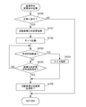
- the control unit 1001 refers to the memory 1002 to determine whether automatic coordinate direction change processing is being performed (S1500).
- the automatic coordinate direction change process is a process in which the control unit 1001 automatically executes a coordinate direction change instruction regardless of the coordinate direction change instruction received by the communication unit 1004.
- the automatic coordinate direction change process is executed prior to the reception of the coordinate direction change instruction when the communication unit 1004 receives the image direction change instruction.
- control unit 1001 When the automatic coordinate direction change process is not executed (No in S1500), the control unit 1001 reads an argument of the coordinate direction change instruction received by the communication unit 1004, and changes the image direction parameter on the memory 1002. Furthermore, the control unit 1001 performs the above-described automatic image direction change processing (S1501).
- control unit 1001 executes an instruction to automatically rotate the captured image at the same angle as the coordinate system change instruction that allows the coordinate system to be rotated. That is, the control unit 1001 executes the received coordinate direction change instruction and automatically executes the image direction change instruction in step S1501.
- step S1501 When automatic image direction change processing is started in step S1501, the control unit 1001 causes the memory 1002 to hold information indicating that automatic image direction change processing is being performed (S1502).
- the information indicating that the automatic image direction change processing is being executed indicates, for example, that the automatic image direction change processing flag is set, indicating that the automatic image direction change processing is being performed, and indicating that the flag is not being executed.
- the control unit 1001 uses the timer unit 1005 to start a timer (S1503).
- This timer is a timer for continuing the state in which the image direction parameter has been changed by the automatic image direction changing process for a predetermined time after the start of the automatic image direction changing process.
- the timer value of this timer may be preset by the user, and may be several hundreds of milliseconds to several seconds.
- the control unit 1001 ends the coordinate direction changing process.
- the timer may be started when the communication unit 1004 receives a coordinate direction change command, not when the automatic image direction change process is started. In this way, it is possible to continue the state in which the image orientation parameter has been changed by the automatic image orientation changing process for a predetermined time after receiving the command.
- the control unit 1001 performs control to execute the coordinate direction change instruction and the image direction change instruction prior to the reception of the image direction change instruction.
- the coordinate direction change instruction is an instruction received by the communication unit 1004.
- the image direction change instruction is an instruction executed by the control unit 1001 performing automatic image direction change processing.
- the imaging apparatus 1000 can output the captured image (the captured image 1072 in FIG. 6) of the image direction after the change, and change the imaging range based on the coordinates after the change (coordinate 1083 in FIG. 7). . Therefore, the captured image can be output in a state where the image direction (forward direction / reverse direction) and the coordinate direction (forward direction / reverse direction) coincide with each other, and the imaging range can be changed. In this manner, only the coordinate direction is changed (coordinate 1083 in FIG. 7) in the state where the image direction is not changed (captured image 1071 in FIG. 6), and the image direction (forward direction / reverse direction) of the captured image It is possible to prevent the coordinate direction (forward direction / reverse direction) from being inconsistent.
- the control unit 1001 deletes the timer (S1510).
- This timer is a timer activated in step S1403 of FIG. 4C described above. This timer is a timer for continuing the state in which the coordinate direction parameter has been changed by the automatic coordinate direction changing process.
- the control unit 1001 reads an argument of the received coordinate direction change instruction, and changes a coordinate direction parameter on the memory 1002. Further, the automatic coordinate direction changing process is ended (S1511).
- the direction of the captured image is rotated so that the coordinate direction parameter changed by the automatic coordinate direction changing process is returned to the state before the automatic coordinate direction changing process is performed.
- step S1411 by performing the process of step S1411, the control unit 1001 rotates the coordinates by the angle instructed by the received coordinate direction change instruction from the state before the automatic coordinate direction change process is performed.
- step S1511 the control unit 1001 ends the coordinate direction change process.
- the automatic coordinate direction changing process is a process executed after the communication unit 1004 receives an image direction change command. That is, when the automatic coordinate direction change process is being executed (Yes in S1500), the communication unit 1004 has already received the image direction change command and the command has been executed. In this state, by executing the processing of step S 1511, the control unit 1001 can execute the coordinate direction change instruction received by the communication unit 1004 and the image direction change instruction received by the communication unit 1004.
- the control unit 1001 when the control unit 1001 receives the coordinate direction change command while the automatic coordinate direction change processing is being executed, the control unit 1001 ends the automatic coordinate direction change processing and executes the coordinate direction change command and the image direction change command. Do.
- the imaging apparatus 1000 can output the captured image (the captured image 1072 in FIG. 6) of the image direction after the change, and change the imaging range based on the coordinates after the change (coordinate 1083 in FIG. 7). . Therefore, a captured image can be output in a state in which the image direction (forward direction / reverse direction) and the coordinate direction (forward direction / reverse direction) match, and the imaging range can be changed.
- the imaging device 1000 can execute the coordinate direction change instruction such that the imaging direction and the coordinate direction always coincide with each other.
- the automatic change process time-out process is a process that is executed when a predetermined time elapses after one of the automatic coordinate direction change process and the automatic image direction change process is performed. Whether or not the predetermined time has elapsed is determined using a timer activated in step S1403 of FIG. 4C or step S1503 of FIG. 4D.
- the automatic change processing time-out process may be executed when a predetermined time has elapsed since one of the coordinate direction change instruction and the image direction change instruction has been received.
- the timer may start counting from the time when the coordinate direction change instruction or the image direction change instruction is received.
- control unit 1001 ends the automatic coordinate direction change process or the automatic image direction change process. Then, the information on the memory 1002 indicating that the automatic coordinate direction changing process or the automatic image direction changing process is being executed is deleted.
- control unit 1001 ends the execution of the image direction change instruction or the coordinate direction change instruction received by the communication unit 1004.
- the control unit 1001 receives the received instruction ((1) The image orientation or coordinate direction is rotated to return to the state before execution of the image orientation change instruction and the coordinate orientation change instruction. Therefore, only one of the image direction change instruction and the coordinate direction change instruction is not executed. Therefore, the direction (positive direction / reverse direction) of the coordinate system of the imaging device 1000 and the image direction (positive direction / It is possible to prevent the reverse direction) from becoming unmatched.
- the imaging device 1000 can execute the coordinate direction change instruction such that the imaging direction and the coordinate direction always coincide with each other.
- the imaging apparatus 1000 can prevent a state in which only one of the image direction and the coordinate direction is changed.
- the direction of the distributed imaging image can be made to coincide with the direction of the instruction for changing the imaging range. . Therefore, the change of the imaging range in line with the user's intention can be realized.
- the control unit 1001 changes the automatic coordinate direction
- the instruction or the automatic image reorientation instruction may be ended.
- the control unit 1001 performs automatic operation.
- the coordinate direction change instruction or the automatic image direction change instruction may be ended.
- the user when the user desires to execute either the image orientation change instruction or the coordinate orientation change instruction, the user is made to execute the instruction after a predetermined time has elapsed since the instruction was received. Can. Also, when the user desires to execute both the image direction change instruction and the coordinate direction change instruction, the coordinates of the imaging device 1000 are received after one instruction is received until the other instruction is received. It is possible to prevent the direction of the system and the image direction of the captured image from being inconsistent.
- a normal response or an error response may be transmitted to the client of the request source in response to each instruction shown in FIGS. 5A to 5C described in the first embodiment. That is, the imaging apparatus 1000 transmits a normal response to the client 3000 of the instruction request source when the instruction from the client 3000 is normally processed. Further, when the command from the client 3000 is not processed normally, the imaging apparatus 1000 transmits an error response to the client 3000 of the command request source. In this way, the client can more easily understand the processing result and processing timing of each instruction.
- Example 2 Second Embodiment
- the present invention is applied to an imaging apparatus having a so-called digital PTZ (Pan Tilt Zoom) function of changing a captured image displayed on a client by changing an area for trimming the captured image.
- digital PTZ Pan Tilt Zoom
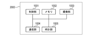
- FIG. 1C An imaging apparatus 2000 according to a second embodiment is shown in FIG. 1C.
- the imaging apparatus 2000 according to the present embodiment does not have the pan drive mechanism 1101, the tilt drive mechanism 1102, and the zoom mechanism 1103.
- the memory 1002 of the imaging apparatus 2000 holds information indicating that the control unit 1001 has performed the automatic coordinate direction changing process or the automatic image direction changing process. Furthermore, in the present embodiment, the memory 1002 determines whether the automatic coordinate direction processing or the automatic image change instruction is executed in response to an instruction from any of a plurality of clients connected to the network 3020. Hold the information of
- the imaging apparatus 2000 does not have the imaging control unit 1006 as compared with the imaging apparatus 1000 in the first embodiment.
- the control unit 1001 of the imaging apparatus 2000 generates a captured image obtained by cutting out a part of the captured image captured by the imaging unit 1003, and transmits the captured image to the client 3000 via the communication unit 1004.
- the imaging apparatus 2000 receives, from the client 3000, an instruction on a cutout position of a captured image as a trimming parameter.
- the trimming parameter is a parameter for trimming a captured image generated by the imaging unit 1003 and specifying a portion to be distributed to the client.
- the trimming parameter consists of two points (x1, y1) and (x2, y2) represented by an X coordinate indicating the horizontal direction of the captured image and a Y coordinate indicating the vertical direction. Indicates the range to be trimmed.
- the imaging apparatus 2000 in the second embodiment can receive an image coordinate direction change instruction from the client 3000.
- An example of the image coordinate direction change instruction is shown in FIG. 5D.
- the client 3000 can change the direction of the captured image distributed by the imaging device 2000 and the direction of the coordinates of the image captureable range together.
- the details of the change of the image direction and the change of the coordinate direction are the same as the contents described with reference to FIGS. 5B and 5C in the embodiment, and the description will be omitted.
- the imaging apparatus 2000 transmits a normal response to the client 3000 of the instruction request source when the instruction from the client 3000 is normally processed. Also, if the command from the client 3000 is not processed normally, the imaging apparatus 2000 transmits an error response to the client 3000 of the command request source.
- An example of a normal response is shown in FIG. 5E. Also, an example of an error response is shown in FIG. 5F.
- FIGS. 8 and 9A to 9C show a program for causing the control unit 1001 to execute the procedures shown in FIGS. 8 and 9A to 9C.
- the processor incorporated in the control unit 1001 of the imaging apparatus 1000 is a computer, and executes a program read from the memory 1002 incorporated in the imaging apparatus 1000.
- the processes shown in FIGS. 8 and 9A to 9C may be performed by hardware.
- the control unit 1001 waits for an event (S2100).
- the imaging apparatus 2000 receives an image acquisition, an imaging range change instruction reception, an image direction change instruction reception, a coordinate direction change instruction reception, an automatic change processing timeout, and an image coordinate direction change instruction reception event occurs. Judge that there is an event.
- the control unit 1001 of the imaging device 2000 performs distribution image creation processing (S2101). Regarding the delivery image creation processing according to the present embodiment, differences from the processing described using FIG. 4A in the first embodiment will be described.
- the control unit 1001 trims the captured image according to the trimming parameter when the image direction parameter is OFF (positive direction) (No in step S1200 of FIG. 4A) in the distribution image creation processing.
- trimming means cutting out a captured image of an area specified by the trimming parameter from the imaging range of the imaging unit 1003.
- control unit 1001 When the image direction parameter is ON (reverse direction) (Yes in S1200), the control unit 1001 changes the image direction in accordance with the image direction parameter in step S1201 illustrated in FIG. 4A and then trims the captured image in accordance with the trimming parameter. Do. When the captured image is trimmed, the control unit 1001 overwrites the captured image stored in the memory 1002 with the trimmed captured image, and ends the distribution image creation process.
- control unit 1001 When the distribution image creation processing is completed, the control unit 1001 performs transmission processing (S2102). In the transmission process, the control unit 1001 transmits the delivery image trimmed in the delivery image creation process of step S1101 to the client 3000 requesting the video delivery from the imaging apparatus 1000 via the communication unit 1004. After performing the transmission process, the control unit 1001 returns to step S1100 and performs the process.
- the control unit 1001 When the control unit 1001 receives an imaging range change command from the client 3000, the control unit 1001 performs an imaging range change process (S2110).
- the imaging range change command is used to change the range from which the image is cut out of the imaging range.
- the control unit 1001 according to the present embodiment calculates trimming parameters in step S1302 in FIG. 4B after performing the processes in steps S1300 and S1301 illustrated in FIG. 4B. That is, when the acquired coordinate direction parameter is ON (inversion direction), the control unit 1001 reverses the coordinate system as shown by the coordinate 1083 in FIG. 7 to determine the trimming range. On the other hand, when the acquired coordinate direction parameter is OFF (positive direction), the control unit 1001 does not invert the coordinate system as in the coordinate 1082 of FIG. 7 and determines the trimming range.
- the control unit 1001 of the present embodiment obtains the position of the trimming range in coordinates in units of pixels.
- Coordinates 2082 and coordinates 2083 in FIG. 7 are coordinates represented by X coordinates and Y coordinates in pixel units, with the lower left vertex as an origin.
- the control unit 1001 sets two pixel coordinates (x1, y1) and (x2) on the captured image corresponding to two vertices forming a diagonal of the determined trimming range. , Y2) are calculated as trimming parameters.
- the control unit 1001 stores the calculated trimming parameter in the memory 1002.
- the control unit 1001 ends the imaging range change processing.
- control unit 1001 When the control unit 1001 according to the present embodiment receives an image direction change command from the client 3000, the control unit 1001 performs an image direction change process described later with reference to FIG. 9A (S2120).
- control unit 1001 When the control unit 1001 according to the present embodiment receives a coordinate direction change instruction from the client 3000, the control unit 1001 performs coordinate direction change processing described later with reference to FIG. 9B (S2130).
- the control unit 1001 performs an automatic change processing time-out process described later with reference to FIG. 9C when a predetermined time elapses after one of the automatic image direction change process and the automatic coordinate direction change process is performed. (S2140).
- the control unit 1001 may perform an automatic change process time-out process described later with reference to FIG. 9C when a predetermined time has elapsed after receiving one of the image direction change command and the coordinate direction change command.
- control unit 1001 when the control unit 1001 according to the present embodiment receives the image coordinate direction change instruction shown in FIG. 4C from the client 3000, the control unit 1001 performs image coordinate direction change processing described later with reference to FIG. 9C (S2101). When the process of step S2101 ends, the control unit 1001 returns to step S2100 and performs the process.
- control unit 1001 refers to the memory 1002 and determines whether or not automatic image direction change processing is being performed according to the coordinate direction change instruction received from the client 3000 that has transmitted the image direction change instruction (S2400).
- the automatic image direction change process is a process that is executed prior to the reception of the image direction change instruction when the communication unit 1004 receives the coordinate direction change instruction, as described in the first embodiment. That is, when the automatic image direction change process is being performed, the communication unit 1004 has already received the coordinate direction change command. When the automatic image direction change process is not executed, the communication unit 1004 has not received the coordinate direction change instruction.
- step S2400 is performed by referring to the memory 1002.
- the memory 1002 holds information on whether or not the automatic image direction change process has been performed.
- the memory 1002 in the present embodiment is information on which of the plurality of clients connected to the imaging apparatus 1000 via the network 3020, the automatic image direction change processing has been executed in response to a coordinate direction change command from the client. Hold.
- the control unit 1001 executes the automatic image direction changing process
- the control unit 1001 causes the memory 1002 to hold information on which client performs the automatic image direction changing process in response to a coordinate direction change command. Take control.
- control unit 1001 When the automatic image direction change process is not executed (No in S2400), the control unit 1001 performs the process of step S2401. That is, the control unit 1001 determines whether the automatic coordinate direction change processing is being performed according to another image direction change instruction transmitted before the client 3000 that has transmitted the image direction change instruction transmits the image direction change instruction ((1) S2401).
- the automatic coordinate direction changing process is a process that is executed prior to the reception of the coordinate direction changing instruction when the communication unit 1004 receives the image direction changing instruction, as described in the first embodiment. That is, when the automatic coordinate direction changing process is being performed, the communication unit 1004 has already received the image direction change command. When the automatic coordinate direction change process is not executed, the communication unit 1004 has not received the image direction change instruction.
- step S2401 is performed by referring to the memory 1002.
- the memory 1002 holds information on whether or not the automatic coordinate direction changing process has been performed.
- the memory 1002 indicates which of a plurality of clients connected to the imaging apparatus 1000 via the network 3020 the automatic coordinate direction change process has been executed according to the image direction change process from the client. Hold information
- the control unit 1001 executes the automatic coordinate direction changing process
- the control unit 1001 causes the memory 1002 to hold information on which client the automatic coordinate direction changing process is performed in response to an image direction change command. Take control.
- the control unit 1001 transmits an error response to the image direction change command currently being received (S2420). That is, when the communication unit 1004 has already received the image direction change instruction from the client of the image direction change instruction transmission source currently received, the control unit 1001 transmits an error response to the currently received image direction instruction. Do.
- the control unit 1001 when the control unit 1001 continuously receives the image direction change instruction, the control unit 1001 performs control to execute only the first image direction change instruction received.
- the imaging apparatus 1000 according to the present embodiment can prevent duplicate execution of the image direction change instruction according to the instruction from the same client.
- control unit 1001 If automatic coordinate direction change processing is not being performed (S2401: No), the control unit 1001 reads an argument of the received image direction change instruction, and changes the image direction parameter on the memory 1002. Further, automatic coordinate direction change processing is performed (S2402).
- control unit 1001 causes the memory 1002 to hold information indicating that the automatic coordinate direction changing process has been performed (S2403).
- Information indicating that automatic coordinate direction change processing is being performed can be held in the memory 1002 in the same manner as described in the first embodiment.
- control unit 1001 uses the timer unit 1005 to start a timer for the client that has transmitted the image direction change command received this time (S2404).
- control unit 1001 transmits a normal response to the image direction change instruction executed in step S2402 to the client that has transmitted the image direction change instruction (S2412).
- the control unit 1001 in this embodiment executes the image direction change command and the coordinate direction change command prior to the coordinate direction change command from the client that has transmitted the command.
- the image direction change instruction is an image direction change instruction received by the communication unit 1004.
- this coordinate direction change instruction is an instruction executed by the control unit 1001 performing automatic coordinate direction change processing in step S2402.
- control unit 1001 deletes the timer for the client that has transmitted the image direction change command (S2410).
- control unit 1001 reads an argument of the received image direction change instruction, and changes the image direction parameter on the memory 1002. Also, the control unit 1001 ends the automatic image direction changing process (S2411).
- control unit 1001 transmits a normal response to the image direction change instruction executed in step S2411 to the client that has transmitted the image direction change instruction (S2412).
- the image direction change instruction is the image direction change instruction received by the communication unit 1004.
- the coordinate direction change instruction is a coordinate direction change instruction received by the communication unit 1004 before executing the automatic image direction change process.
- the imaging apparatus 1000 can output the captured image (the captured image 1072 of FIG. 6) of the image direction after the change, and change the imaging range based on the coordinates after the change (coordinate 2083 of FIG. 7). . Therefore, the captured image can be output in a state where the image direction (forward direction / reverse direction) and the coordinate direction (forward direction / reverse direction) coincide with each other, and the imaging range can be changed.
- the imaging apparatus 1000 can execute the image direction change instruction such that the imaging direction and the coordinate direction always coincide with each other.
- steps S2400 and S2401 whether the control unit 1001 performs automatic image direction change processing or automatic coordinate direction change processing according to an instruction from the client that has transmitted the image direction change instruction. judge. In this way, when an image direction change instruction is received from the client, the image direction change instruction and the coordinate direction change instruction can be executed prior to the reception of the coordinate direction change instruction from the same client. Thus, control can be performed for each client so that both the image direction and the coordinate direction coincide with each other.
- the control unit 1001 may not determine whether the command is a command issued by the client 3000 that has transmitted the image direction change command. In this case, the client is not distinguished, and both instructions are executed when the pair of instructions are issued to the imaging device. Therefore, even when a plurality of clients issue an image direction change command or a coordinate direction change command, the imaging apparatus 1000 can execute both commands so that the image direction matches the coordinate direction.
- the control unit 1001 of this embodiment executes the coordinate direction change instruction and the image direction change instruction prior to the image direction change instruction from the client that has transmitted the instruction.
- the coordinate direction change instruction is a coordinate direction change instruction received by the communication unit 1004.
- the image orientation change instruction is an instruction executed by the control unit 1001 performing automatic image orientation change processing in step S2502.
- control unit 1001 deletes the timer for the client that has transmitted the coordinate direction change instruction (S2510).
- control unit 1001 reads an argument of the received coordinate direction change instruction, and changes a coordinate direction parameter on the memory 1002. Further, the control unit 1001 ends the automatic coordinate direction changing process (S2511).
- control unit 1001 transmits a normal response to the coordinate direction change instruction executed in step S 2511 to the client that has transmitted the coordinate direction change instruction (S 2512).
- the coordinate direction change instruction is a coordinate direction change instruction received by the communication unit 1004.
- the image direction change instruction is an image direction change instruction received by the communication unit 1004 before the automatic coordinate direction change process is performed.
- the imaging apparatus 1000 can output the captured image (the captured image 1072 of FIG. 6) of the image direction after the change, and change the imaging range based on the coordinates after the change (coordinate 2083 of FIG. 7). . Therefore, the captured image can be output in a state where the image direction (forward direction / reverse direction) and the coordinate direction (forward direction / reverse direction) coincide with each other, and the imaging range can be changed.
- the imaging apparatus 1000 can execute the image direction change instruction such that the imaging direction and the coordinate direction always coincide with each other.
- step 2130 the coordinate direction changing process of step 2130 will be described using FIG. 9B.
- the same process as the image direction change process described above is performed.
- control unit 1001 refers to the memory 1002 and determines whether or not automatic coordinate direction change processing is being performed according to the image direction change instruction received from the client 3000 that has transmitted the coordinate direction change instruction (S2500).
- control unit 1001 determines whether the automatic image direction changing process is performed (S2501).
- the control unit 1001 transmits an error response to the coordinate direction change command currently being received (S2520). That is, when the communication unit 1004 has already received the coordinate direction change command, the control unit 1001 transmits an error response to the coordinate direction command currently being received.
- the control unit 1001 when the control unit 1001 continuously receives the coordinate direction change instruction, the control unit 1001 performs control to execute only the coordinate direction change instruction that is received first.
- the imaging device 1000 according to the present embodiment can prevent the coordinate direction change instruction from being redundantly executed.
- control unit 1001 When the automatic image direction change process is not being executed (No in S2501), the control unit 1001 reads an argument of the received coordinate direction change instruction, and changes a coordinate direction parameter on the memory 1002. Further, automatic image direction change processing is performed (S2502).
- control unit 1001 uses the timer unit 1005 to start a timer for the client that has transmitted the coordinate direction change instruction received this time (S2504).
- control unit 1001 transmits a normal response to the coordinate direction change instruction executed in step S2502 to the client that has transmitted the coordinate direction change instruction (S2512).
- steps S2500 and S2501 whether the control unit 1001 performs automatic image direction change processing or automatic coordinate direction change processing according to an instruction from a client that has transmitted a coordinate direction change instruction. judge.
- the image direction change instruction and the coordinate direction change instruction can be executed prior to the reception of the image direction change instruction from the same client.
- control can be performed for each client so that both the image direction and the coordinate direction coincide with each other.
- the communication unit 1004 receives one of the image direction change instruction and the coordinate direction change instruction from the first client, and then receives the other of the image direction change instruction and the coordinate direction change instruction from the first client.
- the control unit 1001 may not execute the image direction change instruction and the coordinate direction change instruction received from the second client. That is, until a pair of image direction change instruction and coordinate direction change instruction are received from one client, an error is returned to an image direction change instruction or coordinate direction change instruction from another client. Good.
- the client that has transmitted one of the image method change instruction and the coordinate direction change instruction can control the imaging device 2000 without being affected by the instruction from the other client.
- the image direction and the coordinate direction of the imaging device 2000 can be always matched.
- the control unit 1001 may not determine whether the command is a command issued by the client that has transmitted the coordinate direction change command. In this case, the client is not distinguished, and both instructions are executed when the pair of instructions are issued to the imaging device. Therefore, even when a plurality of clients issue an image direction change command or a coordinate direction change command, the imaging apparatus 1000 can execute both commands so that the image direction matches the coordinate direction.
- the control unit 1001 can control to return the image direction or the coordinate direction to the state before the automatic change process (automatic image direction change process or automatic coordinate direction change process). That is, when the automatic image direction changing process is performed, the control unit 1001 rotates the image direction of the cut-out captured image so as to return to the state before the automatic image direction changing process. Further, when the automatic coordinate direction changing process is performed, the control unit 1001 rotates the coordinates so as to return the coordinate direction to the state before the automatic coordinate direction changing process is performed.
- control unit 1001 When the image direction or the coordinate direction is rotated to return to the state before the automatic change process, the control unit 1001 causes the memory 1002 to be in the state before the automatic image direction change process or the automatic coordinate direction change process. It holds information indicating that it has been returned. For example, the control unit 1001 can turn off the flag on the memory 1002 that is set when executing the automatic image direction changing process or the automatic coordinate direction changing process.
- the command from the client can be executed as instructed after a predetermined time has elapsed. it can.
- the control unit 1001 controls to rotate the image direction and the coordinate direction of the extracted captured image so that the communication unit 1004 is in a state before receiving the image direction change instruction or the coordinate direction change instruction. It can be performed. That is, when the communication unit 1004 receives the image direction change instruction and executes the image direction change instruction and the automatic coordinate direction change processing corresponding thereto, the control unit 1001 causes the captured image to be subjected to the image direction change instruction before the image direction change instruction is executed. Rotate it to the state. Furthermore, the control unit 1001 rotates the coordinate direction so as to be in the state before the automatic coordinate direction change processing is performed.
- the control unit 1001 when the communication unit 1004 receives the coordinate direction change instruction and executes the coordinate direction change instruction and the automatic image direction change processing corresponding thereto, the control unit 1001 is in a state before the coordinate direction change instruction is executed. Rotate to become Furthermore, the control unit 1001 rotates the image direction so as to be in the state before the automatic image direction change instruction is executed.
- control unit 1001 restores the memory 1002 to the state before the automatic image direction change processing or the automatic coordinate direction change processing. Hold information that indicates that.
- control unit 1001 causes the client that has transmitted the image direction change instruction or the coordinate direction change instruction to execute the image direction change instruction or the coordinate direction change instruction before the image direction or the coordinate direction of the cut out captured image is executed. Notify that it has been returned to the state of.
- the control unit 1001 changes the coordinate direction change instruction received by the communication unit 1004 and the automatic operation.
- the captured image and the coordinate system can be rotated to return to the state before the image orientation change processing is performed.
- control unit 1001 changes the image direction change instruction and the automatic coordinate direction received by the communication unit 1004.
- the captured image and coordinate system can be rotated to return to the state before the processing was performed.
- the clock unit 1005 starts counting after receiving the automatic image direction change process or the automatic coordinate direction change process, but the clock unit 1005 receives the image direction change command or the coordinate direction change command.
- the counting may be started from the moment when the
- control unit 1001 instructs the image direction change instruction and the coordinate direction. Control can be performed to rotate the captured image and the coordinate system so as to return to the state before the change instruction is executed.
- control unit 1001 determines whether automatic change processing (automatic image direction change processing or automatic coordinate direction change processing) is performed with reference to the memory 1002 (S2700). When the automatic change process is being performed (Yes in S2700), the control unit 1001 deletes all the timers in operation using the clock unit 1005 (S2710).
- the control unit 1001 when the control unit 1001 is executing the automatic change processing, the imaging device 2000 is in a state of receiving and executing only one of the image direction change instruction and the coordinate direction change instruction from one client. .
- the control unit 1001 rotates the image direction or the coordinate direction so as to return to the state before the execution of the command received from the client (S2711). Then, the control unit 1001 shifts the processing to step S2701 described later.
- step S2701 the control unit 1001 updates both the image direction parameter and the coordinate direction parameter on the memory 1002 according to the image / coordinate direction argument of the received image coordinate direction change command.
- step S2702 the control unit 1001 transmits a normal response to the transmission source of the image coordinate direction change instruction (S2702).
- control unit 1001 when the control unit 1001 receives the image coordinate direction change command while executing the automatic image direction change processing or the automatic coordinate direction change processing, the control unit 1001 receives the command received by the communication unit 1004 and the automatic change processing. After changing the image direction and coordinate direction to the state before execution, an image coordinate direction change instruction is executed.
- the imaging apparatus 1000 can output the captured image (the captured image 1072 of FIG. 6) of the image direction after the change, and change the imaging range based on the coordinates after the change (coordinate 2083 of FIG. 7). . Therefore, the captured image can be output in a state where the image direction (forward direction / reverse direction) and the coordinate direction (forward direction / reverse direction) coincide with each other, and the imaging range can be changed.
- the imaging device 2000 can prevent the direction of the image and the direction of the coordinates of the image captureable range from being changed to one side.
- the processing in the case where a plurality of clients 3000 are connected to the imaging apparatus 1000 via the network 3020 has been described. Further, in the present embodiment, the processing in the case of performing a normal response indicating that the instruction has been successfully executed or an error response indicating that the instruction has not been executed is performed in response to the instruction from the client 3000. Furthermore, in the present embodiment, the process in the case where the image coordinate direction change instruction is received from the client 3000 has been described. These processes are not limited to the case where the present invention is applied to an imaging apparatus having a so-called digital PTZ function as in the present embodiment, and can also be applied to the imaging apparatus described in the first embodiment.
- Example 3 In the third embodiment, a client application for the client 3000 to transmit an image direction change instruction shown in FIG. 5B or a coordinate direction change instruction shown in FIG. 5C to the imaging apparatus 1000 will be described.
- FIGS. 10A and 10B A process when the client 3000 transmits a coordinate direction change instruction or an image direction change instruction to the imaging apparatus 1000 will be described using the flowcharts shown in FIGS. 10A and 10B.
- the processing flow of FIGS. 10A and 10B shows a program for causing the control unit 3001 of the client 3000 to execute the procedure shown in FIGS. 10A and 10B.
- the processor incorporated in the control unit 3001 is a computer, and executes a program read from the memory 3002 incorporated in the client 3000.
- the processes of FIGS. 10A and 10B may be performed using hardware.
- the control unit 3001 determines whether the coordinate direction change command is normally executed in the imaging apparatus 1000 (S3100). The control unit 3001 can determine, for example, based on the content of the response from the imaging device 1000 to the coordinate direction change instruction, whether the coordinate direction change instruction has been successfully executed.
- the control unit 3001 ends the process.
- the control unit 3001 performs automatic image direction change processing (S3101).
- the automatic image direction change processing when an instruction to transmit a coordinate direction change instruction to the imaging device 1000 is received, an image is automatically automatically transmitted prior to reception of an instruction to transmit an image direction change instruction to the imaging device. It refers to processing of transmitting a direction change command to the imaging device 1000.
- an image direction change instruction can be automatically transmitted to the imaging device 1000.
- the coordinate direction change instruction to the imaging device and the image are performed prior to the client instruction to transmit the image direction change instruction to the imaging device 1000. It is possible to execute a direction change instruction.
- control unit 3001 starts the timer using the timer unit 3006 (S3102). This timer measures how much time has elapsed in the time to continue the state in which the image direction of the captured image is changed by the image direction change command automatically transmitted in step S3101.
- the control unit 3001 determines whether a predetermined time has elapsed since the timer was started (S3103).
- the time used for the determination of step S3103 can be set arbitrarily. If a predetermined time has elapsed after activating the timer (Yes in S3103), the control unit 3001 deletes the timer (S3104). Then, the control unit 3001 ends the automatic image direction changing process (S3106).
- the control unit 3001 rotates the current captured image and the angle by which the captured image is rotated by the image orientation change instruction in the direction opposite to the direction in which the captured image is rotated by the image orientation change command transmitted to the imaging apparatus 1000 in step S3101. A command to cause the image capturing apparatus 1000 to transmit the command. In this manner, after the control unit 3001 automatically transmits the image direction change instruction to the imaging apparatus 1000 in step 3101, the control unit 3001 returns to the state before the image direction change instruction is transmitted after a predetermined time has elapsed. Rotate the captured image.
- step S3103 determines whether the predetermined time has not elapsed since the activation of the timer (No in S3103). If it is determined in step S3103 that the predetermined time has not elapsed since the activation of the timer (No in S3103), the control unit 3001 determines whether the user has issued an instruction to change the image direction to the imaging apparatus 1000 (S3105). When there is no instruction from the user (No in S3105), the control unit 3001 repeats the process of step S3103.
- the control unit 3001 ends the automatic image direction change process performed in step S3101. That is, the control unit 3001 captures the current image by the angle at which the captured image is rotated by the image orientation change instruction in the opposite direction to the direction in which the captured image is rotated by the image orientation change command transmitted to the imaging device 1000 in step S3101. An instruction to rotate the image is transmitted to the imaging apparatus 1000. In this manner, it is possible to prevent the image orientation change instruction instructed by the user and the automatic image orientation change instruction issued in step S3101 from being redundantly executed.
- the coordinate direction change instruction to be transmitted is executed in the imaging apparatus 1000 according to the instruction from the user.
- an image direction change instruction to be transmitted according to a user's instruction is executed in the imaging apparatus 1000. Accordingly, the image direction and the coordinate direction can be made coincident.
- FIG. 10B a case where the client 3000 transmits an image direction change command to the imaging apparatus 1000 will be described using FIG. 10B. Also in the case of transmitting an image direction change command to the imaging apparatus 1000, the same processing as the processing described using FIG. 10A is performed.
- control unit 3001 determines whether the image direction change command is normally executed in the imaging apparatus 1000 (S4100).
- the control unit 3001 ends the process.
- the control unit 3001 performs automatic coordinate direction change processing (S4101).
- the automatic coordinate direction changing process when an instruction to transmit an image direction change instruction to the imaging device 1000 is received, coordinates are automatically adjusted prior to reception of an instruction to transmit a coordinate direction change instruction to the imaging device. It refers to processing of transmitting a direction change command to the imaging device 1000.
- control unit 3001 starts the timer using the timer unit 3006 (S4102).
- control unit 3001 determines whether a predetermined time has elapsed since the timer was started (S4103).
- control unit 3001 deletes the timer (S4104). Then, the control unit 3001 ends the automatic coordinate direction changing process (S4106).
- step S4103 determines whether the predetermined time has not elapsed since the activation of the timer (No in S4103). If it is determined in step S4103 that the predetermined time has not elapsed since the activation of the timer (No in S4103), the control unit 3001 determines whether the user has issued an instruction to change the coordinate direction to the imaging apparatus 1000 (S4105). If there is no instruction from the user (No in S4105), the control unit 3001 repeats the processing in step S4103.
- control unit 3001 ends the automatic image direction change process performed in step S3101.
- the imaging device 1000 executes an image direction change instruction to be transmitted in response to the user's instruction.
- a coordinate direction change instruction to be transmitted according to a user's instruction is executed in the imaging apparatus 1000. Accordingly, the image direction and the coordinate direction can be made coincident.
- control unit 3001 when the control unit 3001 receives an instruction to transmit one of the image direction change instruction and the coordinate direction change instruction to the imaging device 1000, the control unit 3001 receives the other instruction from the image direction change instruction and the coordinate direction change instruction. Prior to the reception of the instruction to transmit, control is performed to cause the imaging device 1000 to execute the image direction change instruction and the coordinate direction change instruction.
- the client 3000 can prevent the direction of the image and the direction of the coordinates of the image captureable range from being changed by only one in the imaging device to be controlled. Therefore, when changing the imaging range while looking at the captured image distributed from the imaging device 1000, it becomes possible to change the imaging range in the same direction as the direction of the captured image distributed. Therefore, it is possible to realize the change of the imaging range in accordance with the user's intention.
- the embodiment is not necessarily limited to the above, and may be partially modified.
- the interface for image orientation change and coordinate orientation change has been described for the case of specifying either the forward orientation or the reverse orientation, but it is not limited to this. It may be an interface that allows specification every 90 degrees or specification once.
- the present invention is also realized by executing the following processing. That is, software (program) for realizing the functions of the above-described embodiments is supplied to a system or apparatus via a network or various storage media, and a computer (or CPU, MPU or the like) of the system or apparatus reads the program. It is a process to execute.
- imaging device 1001 control unit 1002 memory 1004 communication unit 1006 imaging control unit
Landscapes
- Engineering & Computer Science (AREA)
- Multimedia (AREA)
- Signal Processing (AREA)
- Human Computer Interaction (AREA)
- Studio Devices (AREA)
- Closed-Circuit Television Systems (AREA)
- Editing Of Facsimile Originals (AREA)
- User Interface Of Digital Computer (AREA)
Abstract
Description
本実施例に係る撮像システムの構成を図1Aに示す。本実施例に係る撮像システムでは、撮像装置1000がネットワーク3020を介してクライアント3000に接続される。撮像装置1000は撮像した撮像画像をネットワーク3020を介してクライアント3000に配信する。
まず制御部1001は、メモリ1002を参照して、自動座標方向変更処理を実行しているかどうか判定する(S1500)。ここで、自動座標方向変更処理とは、通信部1004受信した座標方向変更命令によらずに、制御部1001が自動的に座標方向変更命令を実行する処理である。自動座標方向変更処理は、通信部1004が画像方向変更命令を受信すると、座標方向変更命令の受信に先立って実行される。
実施例2では、撮像画像をトリミングする領域を変更することによってクライアントに表示される撮像画像を変更する、いわゆるデジタルPTZ(Pan Tilt Zoom)機能を有する撮像装置に本発明を適用する場合について説明する。
実施例3では、撮像装置1000に対して、図5Bに示す画像方向変更命令、又は、図5Cに示す座標方向変更命令をクライアント3000が送信するためのクライアントアプリケーションについて説明する。
実施形態は必ずしも上述の限りでなく、部分的に変更されてもよい。実施例1から実施例3では画像方向変更、座標方向変更のインタフェースは、正向き/反転向きのいずれかを指定する場合について説明したがこの限りではない。90度毎の指定や、1度毎の指定ができるようなインタフェースであってもよい。
1001 制御部
1002 メモリ
1004 通信部
1006 撮像制御部
Claims (17)
- 撮像手段と、
前記撮像手段の撮像方向を表すために用いる座標系を保持する保持手段と、
前記撮像手段が撮像した撮像画像を所定の角度回転させる第1の命令と、前記保持手段に保持された前記座標系を原点を中心として前記所定の角度回転させる第2の命令と、前記座標系における前記撮像方向を特定するための特定情報とを受信する受信手段と、
前記特定情報により特定される前記撮像方向に前記撮像手段の撮像方向を変更する制御を行う変更制御手段と、
前記受信手段が前記第1の命令及び前記第2の命令のうち一方の命令を受信すると、前記第1の命令及び前記第2の命令のうち他方の命令の受信に先立って、前記第1の命令及び前記第2の命令を実行させる制御を行う制御手段とを有することを特徴とする撮像装置。 - 前記受信手段が前記第1の命令及び前記第2の命令のうち一方を受信してから所定時間経過しても他方の命令を受信しない場合には、前記制御手段は前記第1の命令及び前記第2の命令を実行させる前の状態に戻すように前記撮像画像及び前記座標系を回転させる制御を行うことを特徴とする請求項1に記載の撮像装置。
- 前記受信手段が前記第1の命令及び前記第2の命令のうち一方の命令を連続して受信した場合には、前記制御手段は最初に受信した命令のみを実行させる制御を行うことを特徴とする請求項1に記載の撮像装置。
- 前記受信手段は複数の制御装置から命令を受信し、
前記受信手段が第1の制御装置から前記第1の命令及び前記第2の命令のうち一方を受信してから前記第1の制御装置から前記第1の命令及び前記第2の命令のうち他方の命令を受信するまでは、前記制御手段は第2の制御装置から受信した前記第1の命令及び前記第2の命令を実行しないことを特徴とする請求項1に記載の撮像装置。 - 前記受信手段は前記第1の命令として前記撮像画像の上下及び左右の両方を反転させる命令を受信し、前記第2の命令として前記座標系の上下及び左右の両方を反転させる命令を受信することを特徴とする請求項1に記載の撮像装置。
- 撮像手段と、
前記撮像手段の撮像範囲における領域を表すために用いる座標系を保持する保持手段と、
前記撮像範囲上の領域から切り出した撮像画像を所定の角度回転させる第1の命令と、前記保持手段に保持された前記座標系を原点を中心として前記所定の角度回転させる第2の命令と、前記撮像範囲から前記撮像画像を切り出す領域を前記座標系において特定するための特定情報とを受信する受信手段と、
前記特定情報により特定される前記座標系における領域の前記撮像画像を切り出す切出手段と、
前記受信手段が前記第1の命令及び前記第2の命令のうち一方の命令を受信すると、前記第1の命令及び前記第2の命令のうち他方の命令の受信に先立って、前記第1の命令及び前記第2の命令を実行させる制御を行う制御手段とを有することを特徴とする撮像装置。 - 撮像手段の撮像方向を表すために用いる座標系を保持する保持手段を有する撮像装置を制御する制御装置であって、
前記座標系における撮像方向を特定するための特定手段と、
前記特定手段が特定した撮像方向において前記撮像手段が撮像した撮像画像を所定の角度回転させる第1の命令及び前記保持手段に保持された前記座標系を原点を中心として前記所定の角度回転させる第2の命令を前記撮像装置に対して送信する制御を行う送信制御手段と、
前記送信制御手段が前記第1の命令及び前記第2の命令のうち一方の命令を前記撮像装置に送信する指示を受けると、前記第1の命令及び前記第2の命令のうち他方の命令を前記撮像装置に送信する指示の受信に先立って、前記撮像装置に前記第1の命令及び前記第2の命令を実行させる制御を行う制御手段とを有することを特徴とする制御装置。 - 撮像手段の撮像範囲における領域を表すために用いる座標系を保持する保持手段を有する撮像装置を制御する制御装置であって、
前記座標系における領域を特定するための特定手段と、
前記特定手段が特定した前記座標系における領域に応じた前記撮像範囲上の領域の撮像画像を所定の角度回転させる第1の命令及び前記保持手段に保持された前記座標系を原点を中心として前記所定の角度回転させる第2の命令を前記撮像装置に対して送信する制御を行う送信制御手段と、
前記送信制御手段が前記第1の命令及び前記第2の命令のうち一方の命令を前記撮像装置に送信する指示を受けると、前記第1の命令及び前記第2の命令のうち他方の命令を前記撮像装置に送信する指示の受信に先立って、前記撮像装置に前記第1の命令及び前記第2の命令を実行させる制御を行う制御手段とを有することを特徴とする制御装置。 - 前記第1の命令又は前記第2の命令のうち一方の命令を前記撮像装置に送信する指示を受けた場合に、前記制御手段は他方の命令をあわせて送信するか問い合わせる問い合わせ出力を出力することを特徴とする請求項7又は請求項8に記載の制御装置。
- 保持手段が、撮像手段の撮像方向を表すために用いる座標系を保持する保持ステップと、
受信手段が、前記撮像手段が撮像した撮像画像を所定の角度回転させる第1の命令と、前記保持ステップにおいて保持された前記座標系を原点を中心として前記所定の角度回転させる第2の命令と、前記座標系における前記撮像方向を特定するための特定情報とを受信する受信ステップと、
変更制御手段が、前記特定情報により特定される前記撮像方向に前記撮像手段の撮像方向を変更する制御を行う変更制御ステップと、
制御手段が、前記受信ステップにおいて前記第1の命令及び前記第2の命令のうち一方の命令を受信すると、前記第1の命令及び前記第2の命令のうち他方の命令の受信に先立って、前記第1の命令及び前記第2の命令を実行させる制御を行う制御ステップとを有することを特徴とする撮像方法。 - 保持手段が、撮像手段の撮像範囲における領域を表すために用いる座標系を保持する保持ステップと、
受信手段が、前記撮像範囲上の領域から切り出した撮像画像を所定の角度回転させる第1の命令と、前記保持ステップにおいて保持された前記座標系を原点を中心として前記所定の角度回転させる第2の命令と、前記撮像範囲から前記撮像画像を切り出す領域を前記座標系において特定するための特定情報とを受信する受信ステップと、
切出手段が、前記特定情報により特定される前記座標系における領域の前記撮像画像を切り出す切出ステップと、
制御手段が、前記受信ステップにおいて前記第1の命令及び前記第2の命令のうち一方の命令を受信すると、前記第1の命令及び前記第2の命令のうち他方の命令の受信に先立って、前記第1の命令及び前記第2の命令を実行させる制御を行う制御ステップとを有することを特徴とする撮像方法。 - 撮像手段の撮像方向を表すために用いる座標系を保持する保持手段を有する撮像装置の制御方法であって、
特定手段が、前記座標系における撮像方向を特定する特定ステップと、
送信制御手段が、前記特定ステップにおいて特定した撮像方向において前記撮像手段が撮像した撮像画像を所定の角度回転させる第1の命令及び前記保持手段に保持された前記座標系を原点を中心として前記所定の角度回転させる第2の命令を前記撮像装置に対して送信する制御を行う送信制御ステップと、
制御手段が、前記送信制御ステップにおいて前記第1の命令及び前記第2の命令のうち一方の命令を前記撮像装置に送信する指示を受けると、前記第1の命令及び前記第2の命令のうち他方の命令を前記撮像装置に送信する指示の受信に先立って、前記撮像装置に前記第1の命令及び前記第2の命令を実行させる制御を行う制御ステップとを有することを特徴とする制御方法。 - 撮像手段の撮像範囲における領域を表すために用いる座標系を保持する保持手段を有する撮像装置の制御方法であって、
特定手段が、前記座標系における領域を特定する特定ステップと、
送信制御手段が、前記特定ステップにおいて特定した前記座標系における領域に応じた前記撮像範囲上の領域の撮像画像を所定の角度回転させる第1の命令及び前記保持手段に保持された前記座標系を原点を中心として前記所定の角度回転させる第2の命令を前記撮像装置に対して送信する制御を行う送信制御ステップと、
制御手段が、前記送信制御ステップにおいて前記第1の命令及び前記第2の命令のうち一方の命令を前記撮像装置に送信する指示を受けると、前記第1の命令及び前記第2の命令のうち他方の命令を前記撮像装置に送信する指示の受信に先立って、前記撮像装置に前記第1の命令及び前記第2の命令を実行させる制御を行う制御ステップとを有することを特徴とする制御方法。 - 撮像手段を有する撮像装置に、
前記撮像手段の撮像方向を表すために用いる座標系を保持する保持手順と、
前記撮像手段が撮像した撮像画像を所定の角度回転させる第1の命令と、前記保持手順において保持された前記座標系を原点を中心として前記所定の角度回転させる第2の命令と、前記座標系における前記撮像方向を特定するための特定情報とを受信する受信手順と、
前記特定情報により特定される前記撮像方向に前記撮像手段の撮像方向を変更する制御を行う変更制手順と、
前記受信手順において前記第1の命令及び前記第2の命令のうち一方の命令を受信すると、前記第1の命令及び前記第2の命令のうち他方の命令の受信に先立って、前記第1の命令及び前記第2の命令を実行させる制御を行う制御手順とを実行させるためのプログラム。 - 撮像手段を有する撮像装置に、
前記撮像手段の撮像範囲における領域を表すために用いる座標系を保持する保持手順と、
前記撮像範囲上の領域から切り出した撮像画像を所定の角度回転させる第1の命令と、前記保持手順において保持された前記座標系を原点を中心として前記所定の角度回転させる第2の命令と、前記撮像範囲から前記撮像画像を切り出す領域を前記座標系において特定するための特定情報とを受信する受信手順と、
前記特定情報により特定される前記座標系における領域の前記撮像画像を切り出す切出手順と、
前記受信手順において前記第1の命令及び前記第2の命令のうち一方の命令を受信すると、前記第1の命令及び前記第2の命令のうち他方の命令の受信に先立って、前記第1の命令及び前記第2の命令を実行させる制御を行う制御手順とを実行させるためのプログラム。 - 撮像手段の撮像方向を表すために用いる座標系を保持する保持手段を有する撮像装置を制御する制御装置に、
前記座標系における撮像方向を特定するための特定手順と、
前記特定手順において特定した撮像方向において前記撮像手段が撮像した撮像画像を所定の角度回転させる第1の命令及び前記保持手段に保持された前記座標系を原点を中心として前記所定の角度回転させる第2の命令を前記撮像装置に対して送信する制御を行う送信制御手順と、
前記送信制御手順において前記第1の命令及び前記第2の命令のうち一方の命令を前記撮像装置に送信する指示を受けると、前記第1の命令及び前記第2の命令のうち他方の命令を前記撮像装置に送信する指示の受信に先立って、前記撮像装置に前記第1の命令及び前記第2の命令を実行させる制御を行う制御手順とを実行させるためのプログラム。 - 撮像手段の撮像範囲における領域を表すために用いる座標系を保持する保持手段を有する撮像装置を制御する制御装置に、
前記座標系における領域を特定する特定手順と、
前記特定手順において特定した前記座標系における領域に応じた前記撮像範囲上の領域の撮像画像を所定の角度回転させる第1の命令及び前記保持手段に保持された前記座標系を原点を中心として前記所定の角度回転させる第2の命令を前記撮像装置に対して送信する制御を行う送信制御手順と、
前記送信制御手順において前記第1の命令及び前記第2の命令のうち一方の命令を前記撮像装置に送信する指示を受けると、前記第1の命令及び前記第2の命令のうち他方の命令を前記撮像装置に送信する指示の受信に先立って、前記撮像装置に前記第1の命令及び前記第2の命令を実行させる制御を行う制御手順とを実行させるためのプログラム。
Priority Applications (14)
| Application Number | Priority Date | Filing Date | Title |
|---|---|---|---|
| EP19158823.5A EP3518527A1 (en) | 2011-11-14 | 2011-11-14 | Image pickup apparatus, control apparatus, control method, and program |
| RU2014124140/07A RU2568290C1 (ru) | 2011-11-14 | 2011-11-14 | Устройство съемки изображения, устройство управления, способ управления и машиночитаемый носитель информации |
| PCT/JP2011/076149 WO2013072981A1 (ja) | 2011-11-14 | 2011-11-14 | 撮像装置、制御装置、制御方法、及びプログラム |
| BR112014011632A BR112014011632A2 (pt) | 2011-11-14 | 2011-11-14 | aparelho de captação, aparelho de controle e método de controle de imagem, e programa |
| KR1020147016117A KR101627949B1 (ko) | 2011-11-14 | 2011-11-14 | 촬상 장치, 제어 장치, 제어 방법, 및 컴퓨터 판독가능한 기억 매체 |
| CN201710724687.7A CN107257441B (zh) | 2011-11-14 | 2011-11-14 | 摄像装置、控制装置和控制方法 |
| EP11876003.2A EP2782329B1 (en) | 2011-11-14 | 2011-11-14 | Imaging device, control device, control method and program |
| CN201180074843.0A CN103947182B (zh) | 2011-11-14 | 2011-11-14 | 摄像装置、控制装置和控制方法 |
| JP2013543999A JP5883024B2 (ja) | 2011-11-14 | 2011-11-14 | 制御装置、制御方法、及びプログラム |
| US13/672,983 US9635221B2 (en) | 2011-11-14 | 2012-11-09 | Image capturing apparatus, control apparatus, and control method for distributing captured images to a terminal via a network |
| IN4327CHN2014 IN2014CN04327A (ja) | 2011-11-14 | 2014-06-11 | |
| US15/371,040 US9942458B2 (en) | 2011-11-14 | 2016-12-06 | Image pickup apparatus, control apparatus, and control method for distributing captured images to a terminal via a network |
| US15/485,615 US9787888B2 (en) | 2011-11-14 | 2017-04-12 | Image capturing apparatus, control apparatus, and control method for distributing captured images to a terminal via a network |
| US15/660,821 US9912856B2 (en) | 2011-11-14 | 2017-07-26 | Image capturing apparatus, control apparatus, and control method for distributing captured images to a terminal via a network |
Applications Claiming Priority (1)
| Application Number | Priority Date | Filing Date | Title |
|---|---|---|---|
| PCT/JP2011/076149 WO2013072981A1 (ja) | 2011-11-14 | 2011-11-14 | 撮像装置、制御装置、制御方法、及びプログラム |
Publications (1)
| Publication Number | Publication Date |
|---|---|
| WO2013072981A1 true WO2013072981A1 (ja) | 2013-05-23 |
Family
ID=48280281
Family Applications (1)
| Application Number | Title | Priority Date | Filing Date |
|---|---|---|---|
| PCT/JP2011/076149 Ceased WO2013072981A1 (ja) | 2011-11-14 | 2011-11-14 | 撮像装置、制御装置、制御方法、及びプログラム |
Country Status (9)
| Country | Link |
|---|---|
| US (4) | US9635221B2 (ja) |
| EP (2) | EP2782329B1 (ja) |
| JP (1) | JP5883024B2 (ja) |
| KR (1) | KR101627949B1 (ja) |
| CN (2) | CN107257441B (ja) |
| BR (1) | BR112014011632A2 (ja) |
| IN (1) | IN2014CN04327A (ja) |
| RU (1) | RU2568290C1 (ja) |
| WO (1) | WO2013072981A1 (ja) |
Cited By (4)
| Publication number | Priority date | Publication date | Assignee | Title |
|---|---|---|---|---|
| JP2013258538A (ja) * | 2012-06-12 | 2013-12-26 | Canon Inc | 撮像制御装置、撮像制御方法及びプログラム |
| JP2015080142A (ja) * | 2013-10-18 | 2015-04-23 | キヤノン株式会社 | 撮像装置、撮像システム、撮像装置の制御方法、撮像システムの制御方法、及びプログラム |
| JPWO2016038976A1 (ja) * | 2014-09-11 | 2017-06-22 | 富士フイルム株式会社 | マルチ撮像装置、マルチ撮像方法、プログラム、及び記録媒体 |
| CN108366205A (zh) * | 2013-10-28 | 2018-08-03 | 佳能株式会社 | 摄像设备和摄像设备的控制方法 |
Families Citing this family (8)
| Publication number | Priority date | Publication date | Assignee | Title |
|---|---|---|---|---|
| US10178298B2 (en) * | 2012-12-20 | 2019-01-08 | Sony Corporation | Image processing device, image processing method, and recording medium for optimal trimming of a captured image |
| JP5988860B2 (ja) * | 2012-12-21 | 2016-09-07 | キヤノン株式会社 | 撮像装置及び撮像装置の制御方法 |
| JP6234165B2 (ja) * | 2013-10-28 | 2017-11-22 | キヤノン株式会社 | 撮像装置、外部装置、撮像システム、撮像装置の制御方法、外部装置の制御方法、撮像システムの制御方法、及びプログラム |
| CN105049813A (zh) * | 2015-08-11 | 2015-11-11 | 小米科技有限责任公司 | 控制视频画面的方法、装置及终端 |
| CN106027903B (zh) * | 2016-06-29 | 2020-03-31 | 努比亚技术有限公司 | 取景界面旋转装置及方法 |
| JP6968610B2 (ja) * | 2017-08-01 | 2021-11-17 | キヤノン株式会社 | 撮像装置、情報処理方法及びプログラム |
| JP2020019250A (ja) * | 2018-08-02 | 2020-02-06 | キヤノン株式会社 | 画像処理装置、画像処理方法、及びプログラム |
| JP7468391B2 (ja) * | 2021-02-09 | 2024-04-16 | 株式会社Jvcケンウッド | 撮像装置および撮像処理方法 |
Citations (4)
| Publication number | Priority date | Publication date | Assignee | Title |
|---|---|---|---|---|
| JP2000209575A (ja) * | 1999-01-11 | 2000-07-28 | Star Micronics Co Ltd | 監視カメラ装置 |
| JP2008153842A (ja) | 2006-12-15 | 2008-07-03 | Hitachi Kokusai Electric Inc | 監視システム |
| JP2008205796A (ja) * | 2007-02-20 | 2008-09-04 | Canon Inc | 設置型撮像装置 |
| JP2010283529A (ja) * | 2009-06-03 | 2010-12-16 | Canon Inc | 表示制御装置、表示装置の制御方法、プログラム、記憶媒体 |
Family Cites Families (24)
| Publication number | Priority date | Publication date | Assignee | Title |
|---|---|---|---|---|
| JP4169462B2 (ja) * | 1999-08-26 | 2008-10-22 | 株式会社リコー | 画像処理方法及び装置、デジタルカメラ、画像処理システム、並びに、画像処理プログラムを記録した記録媒体 |
| JP2001100281A (ja) * | 1999-09-30 | 2001-04-13 | Matsushita Electric Ind Co Ltd | 動作履歴を記録する監視カメラ装置と動作履歴の記録方法 |
| AU2001271370A1 (en) * | 2000-06-22 | 2002-01-02 | Vicon Industries, Inc. | Dome housed video camera assembly with 180 degree tilt motion |
| US20110058036A1 (en) * | 2000-11-17 | 2011-03-10 | E-Watch, Inc. | Bandwidth management and control |
| US20050091311A1 (en) * | 2003-07-29 | 2005-04-28 | Lund Christopher D. | Method and apparatus for distributing multimedia to remote clients |
| RU2251712C1 (ru) * | 2003-09-01 | 2005-05-10 | Государственное унитарное предприятие "Конструкторское бюро приборостроения" | Способ определения координат объекта и оптико-электронное устройство для его осуществления |
| JP4593172B2 (ja) * | 2004-05-25 | 2010-12-08 | 公立大学法人会津大学 | カメラ制御装置 |
| JP2006086714A (ja) * | 2004-09-15 | 2006-03-30 | Elmo Co Ltd | 監視カメラ装置 |
| JP2007049301A (ja) | 2005-08-08 | 2007-02-22 | Casio Comput Co Ltd | 画像処理装置及び画像処理方法 |
| JP4533284B2 (ja) * | 2005-08-30 | 2010-09-01 | キヤノン株式会社 | 追尾撮像装置及びその追尾制御方法、並びに制御プログラム |
| JP5030261B2 (ja) * | 2005-11-16 | 2012-09-19 | キヤノン株式会社 | 映像配信装置、ビューワ装置、映像配信装置の制御方法、ビューワ装置の制御方法およびコンピュータプログラム |
| US20070109417A1 (en) * | 2005-11-16 | 2007-05-17 | Per Hyttfors | Methods, devices and computer program products for remote control of an image capturing device |
| US20070115355A1 (en) * | 2005-11-18 | 2007-05-24 | Mccormack Kenneth | Methods and apparatus for operating a pan tilt zoom camera |
| JP4802012B2 (ja) * | 2006-03-02 | 2011-10-26 | ティーオーエー株式会社 | カメラ制御装置およびカメラ制御方法 |
| JP4717701B2 (ja) * | 2006-04-24 | 2011-07-06 | キヤノン株式会社 | 撮像システム、撮影方向制御方法、及びプログラム |
| EP1959692B9 (en) * | 2007-02-19 | 2011-06-22 | Axis AB | A method for compensating hardware misalignments in a camera |
| EP1981263B1 (en) * | 2007-04-13 | 2019-04-03 | Axis AB | Supporting continuous pan rotation in a pan-tilt camera |
| JP5109803B2 (ja) * | 2007-06-06 | 2012-12-26 | ソニー株式会社 | 画像処理装置、画像処理方法及び画像処理プログラム |
| KR101200491B1 (ko) * | 2008-12-22 | 2012-11-16 | 한국전자통신연구원 | 사람 검출 장치 및 방법 |
| JP2010204276A (ja) * | 2009-03-02 | 2010-09-16 | Sony Corp | 駆動装置および撮像装置 |
| US20110032368A1 (en) * | 2009-08-07 | 2011-02-10 | Nicholas John Pelling | System for Emulating Continuous Pan/Tilt Cameras |
| JP5402431B2 (ja) | 2009-09-11 | 2014-01-29 | 沖電気工業株式会社 | カメラ制御装置 |
| JP5471355B2 (ja) | 2009-11-24 | 2014-04-16 | オムロン株式会社 | 3次元視覚センサ |
| RU110070U1 (ru) * | 2011-06-28 | 2011-11-10 | Российская Федерация, от имени которой выступает Министерство промышленности и торговли Российской Федерации (Минпромторг России) | Система автономной посадки беспилотного летающего аппарата на движущееся судно |
-
2011
- 2011-11-14 JP JP2013543999A patent/JP5883024B2/ja active Active
- 2011-11-14 EP EP11876003.2A patent/EP2782329B1/en not_active Not-in-force
- 2011-11-14 CN CN201710724687.7A patent/CN107257441B/zh active Active
- 2011-11-14 EP EP19158823.5A patent/EP3518527A1/en not_active Withdrawn
- 2011-11-14 WO PCT/JP2011/076149 patent/WO2013072981A1/ja not_active Ceased
- 2011-11-14 KR KR1020147016117A patent/KR101627949B1/ko active Active
- 2011-11-14 RU RU2014124140/07A patent/RU2568290C1/ru active
- 2011-11-14 BR BR112014011632A patent/BR112014011632A2/pt not_active IP Right Cessation
- 2011-11-14 CN CN201180074843.0A patent/CN103947182B/zh active Active
-
2012
- 2012-11-09 US US13/672,983 patent/US9635221B2/en active Active
-
2014
- 2014-06-11 IN IN4327CHN2014 patent/IN2014CN04327A/en unknown
-
2016
- 2016-12-06 US US15/371,040 patent/US9942458B2/en active Active
-
2017
- 2017-04-12 US US15/485,615 patent/US9787888B2/en active Active
- 2017-07-26 US US15/660,821 patent/US9912856B2/en active Active
Patent Citations (4)
| Publication number | Priority date | Publication date | Assignee | Title |
|---|---|---|---|---|
| JP2000209575A (ja) * | 1999-01-11 | 2000-07-28 | Star Micronics Co Ltd | 監視カメラ装置 |
| JP2008153842A (ja) | 2006-12-15 | 2008-07-03 | Hitachi Kokusai Electric Inc | 監視システム |
| JP2008205796A (ja) * | 2007-02-20 | 2008-09-04 | Canon Inc | 設置型撮像装置 |
| JP2010283529A (ja) * | 2009-06-03 | 2010-12-16 | Canon Inc | 表示制御装置、表示装置の制御方法、プログラム、記憶媒体 |
Non-Patent Citations (1)
| Title |
|---|
| See also references of EP2782329A4 |
Cited By (8)
| Publication number | Priority date | Publication date | Assignee | Title |
|---|---|---|---|---|
| JP2013258538A (ja) * | 2012-06-12 | 2013-12-26 | Canon Inc | 撮像制御装置、撮像制御方法及びプログラム |
| JP2015080142A (ja) * | 2013-10-18 | 2015-04-23 | キヤノン株式会社 | 撮像装置、撮像システム、撮像装置の制御方法、撮像システムの制御方法、及びプログラム |
| WO2015056379A1 (en) * | 2013-10-18 | 2015-04-23 | Canon Kabushiki Kaisha | Image pickup apparatus, image capturing system, method of controlling image pickup apparatus, method of controlling image capturing system, and program |
| US10063759B2 (en) | 2013-10-18 | 2018-08-28 | Canon Kabushiki Kaisha | Image pickup apparatus, image capturing system, method of controlling image pickup apparatus, method of controlling image capturing system, and program |
| CN108366205A (zh) * | 2013-10-28 | 2018-08-03 | 佳能株式会社 | 摄像设备和摄像设备的控制方法 |
| CN108366205B (zh) * | 2013-10-28 | 2020-10-30 | 佳能株式会社 | 摄像设备和摄像设备的控制方法 |
| JPWO2016038976A1 (ja) * | 2014-09-11 | 2017-06-22 | 富士フイルム株式会社 | マルチ撮像装置、マルチ撮像方法、プログラム、及び記録媒体 |
| US10298828B2 (en) | 2014-09-11 | 2019-05-21 | Fujifilm Corporation | Multi-imaging apparatus including internal imaging device and external imaging device, multi-imaging method, program, and recording medium |
Also Published As
| Publication number | Publication date |
|---|---|
| US9942458B2 (en) | 2018-04-10 |
| US20170324894A1 (en) | 2017-11-09 |
| IN2014CN04327A (ja) | 2015-09-04 |
| CN107257441B (zh) | 2020-10-30 |
| US9787888B2 (en) | 2017-10-10 |
| JPWO2013072981A1 (ja) | 2015-04-02 |
| BR112014011632A2 (pt) | 2017-05-02 |
| RU2568290C1 (ru) | 2015-11-20 |
| US9635221B2 (en) | 2017-04-25 |
| CN103947182A (zh) | 2014-07-23 |
| EP2782329A1 (en) | 2014-09-24 |
| US9912856B2 (en) | 2018-03-06 |
| CN107257441A (zh) | 2017-10-17 |
| US20130120606A1 (en) | 2013-05-16 |
| KR20140092400A (ko) | 2014-07-23 |
| US20170223255A1 (en) | 2017-08-03 |
| US20170085778A1 (en) | 2017-03-23 |
| EP2782329B1 (en) | 2019-10-16 |
| KR101627949B1 (ko) | 2016-06-07 |
| EP2782329A4 (en) | 2015-07-29 |
| CN103947182B (zh) | 2017-09-08 |
| EP3518527A1 (en) | 2019-07-31 |
| JP5883024B2 (ja) | 2016-03-09 |
Similar Documents
| Publication | Publication Date | Title |
|---|---|---|
| JP5883024B2 (ja) | 制御装置、制御方法、及びプログラム | |
| JP5818910B2 (ja) | 撮像装置、制御装置、制御方法、及びプログラム | |
| JP5925059B2 (ja) | 撮像制御装置、撮像制御方法及びプログラム | |
| JP7013210B2 (ja) | 撮像装置、撮像方法、表示装置および表示方法 | |
| US20150334286A1 (en) | Wireless video camera | |
| JP2005333552A (ja) | パノラマ映像配信システム | |
| JP2019017069A (ja) | 画像処理装置及び画像処理方法 | |
| JP7150456B2 (ja) | 撮像システム、情報処理装置、情報処理装置の制御方法、及び、プログラム | |
| CN104935814A (zh) | 照片拍摄方法和装置 | |
| JP2015204525A (ja) | 情報処理装置、提示方法、及びプログラム | |
| KR20180129667A (ko) | 표시 제어 장치, 표시 제어 방법 및 저장 매체 | |
| JP2016096481A (ja) | 制御装置、撮像システム、制御方法、及び、プログラム | |
| CN110933297A (zh) | 智能摄影系统的摄影控制方法、装置、存储介质及系统 | |
| JP6370443B2 (ja) | 制御装置、撮像装置、制御方法、及びプログラム | |
| JP6104417B2 (ja) | 制御装置、制御方法、及びプログラム | |
| JP2015080142A (ja) | 撮像装置、撮像システム、撮像装置の制御方法、撮像システムの制御方法、及びプログラム | |
| JP6165376B1 (ja) | 制御装置、撮像装置、制御方法、及びプログラム | |
| JP7335463B1 (ja) | 携帯用の撮像装置、映像処理システム、映像処理方法、及び映像処理プログラム | |
| KR101407119B1 (ko) | 초광각 카메라를 이용한 카메라 시스템 | |
| JP2016165137A (ja) | 情報処理装置、情報処理方法及びプログラム |
Legal Events
| Date | Code | Title | Description |
|---|---|---|---|
| 121 | Ep: the epo has been informed by wipo that ep was designated in this application |
Ref document number: 11876003 Country of ref document: EP Kind code of ref document: A1 |
|
| ENP | Entry into the national phase |
Ref document number: 2013543999 Country of ref document: JP Kind code of ref document: A |
|
| NENP | Non-entry into the national phase |
Ref country code: DE |
|
| ENP | Entry into the national phase |
Ref document number: 20147016117 Country of ref document: KR Kind code of ref document: A |
|
| WWE | Wipo information: entry into national phase |
Ref document number: 2011876003 Country of ref document: EP |
|
| ENP | Entry into the national phase |
Ref document number: 2014124140 Country of ref document: RU Kind code of ref document: A |
|
| REG | Reference to national code |
Ref country code: BR Ref legal event code: B01A Ref document number: 112014011632 Country of ref document: BR |
|
| ENP | Entry into the national phase |
Ref document number: 112014011632 Country of ref document: BR Kind code of ref document: A2 Effective date: 20140514 |