WO2013073192A1 - コンデンサおよびその製造方法 - Google Patents
コンデンサおよびその製造方法 Download PDFInfo
- Publication number
- WO2013073192A1 WO2013073192A1 PCT/JP2012/007353 JP2012007353W WO2013073192A1 WO 2013073192 A1 WO2013073192 A1 WO 2013073192A1 JP 2012007353 W JP2012007353 W JP 2012007353W WO 2013073192 A1 WO2013073192 A1 WO 2013073192A1
- Authority
- WO
- WIPO (PCT)
- Prior art keywords
- valve
- capacitor
- height
- island
- sealing
- Prior art date
- Legal status (The legal status is an assumption and is not a legal conclusion. Google has not performed a legal analysis and makes no representation as to the accuracy of the status listed.)
- Ceased
Links
Images


Classifications
-
- H—ELECTRICITY
- H01—ELECTRIC ELEMENTS
- H01G—CAPACITORS; CAPACITORS, RECTIFIERS, DETECTORS, SWITCHING DEVICES, LIGHT-SENSITIVE OR TEMPERATURE-SENSITIVE DEVICES OF THE ELECTROLYTIC TYPE
- H01G9/00—Electrolytic capacitors, rectifiers, detectors, switching devices, light-sensitive or temperature-sensitive devices; Processes of their manufacture
- H01G9/004—Details
- H01G9/08—Housing; Encapsulation
- H01G9/12—Vents or other means allowing expansion
-
- H—ELECTRICITY
- H01—ELECTRIC ELEMENTS
- H01G—CAPACITORS; CAPACITORS, RECTIFIERS, DETECTORS, SWITCHING DEVICES, LIGHT-SENSITIVE OR TEMPERATURE-SENSITIVE DEVICES OF THE ELECTROLYTIC TYPE
- H01G9/00—Electrolytic capacitors, rectifiers, detectors, switching devices, light-sensitive or temperature-sensitive devices; Processes of their manufacture
- H01G9/004—Details
- H01G9/08—Housing; Encapsulation
- H01G9/10—Sealing, e.g. of lead-in wires
-
- Y—GENERAL TAGGING OF NEW TECHNOLOGICAL DEVELOPMENTS; GENERAL TAGGING OF CROSS-SECTIONAL TECHNOLOGIES SPANNING OVER SEVERAL SECTIONS OF THE IPC; TECHNICAL SUBJECTS COVERED BY FORMER USPC CROSS-REFERENCE ART COLLECTIONS [XRACs] AND DIGESTS
- Y02—TECHNOLOGIES OR APPLICATIONS FOR MITIGATION OR ADAPTATION AGAINST CLIMATE CHANGE
- Y02E—REDUCTION OF GREENHOUSE GAS [GHG] EMISSIONS, RELATED TO ENERGY GENERATION, TRANSMISSION OR DISTRIBUTION
- Y02E60/00—Enabling technologies; Technologies with a potential or indirect contribution to GHG emissions mitigation
- Y02E60/13—Energy storage using capacitors
-
- Y—GENERAL TAGGING OF NEW TECHNOLOGICAL DEVELOPMENTS; GENERAL TAGGING OF CROSS-SECTIONAL TECHNOLOGIES SPANNING OVER SEVERAL SECTIONS OF THE IPC; TECHNICAL SUBJECTS COVERED BY FORMER USPC CROSS-REFERENCE ART COLLECTIONS [XRACs] AND DIGESTS
- Y10—TECHNICAL SUBJECTS COVERED BY FORMER USPC
- Y10T—TECHNICAL SUBJECTS COVERED BY FORMER US CLASSIFICATION
- Y10T29/00—Metal working
- Y10T29/43—Electric condenser making
Definitions
- the present invention relates to a capacitor having a pressure valve for discharging gas in an outer case, such as an electric double layer capacitor and an electrolytic capacitor, and a method for manufacturing the same.
- ⁇ Capacitors such as electric double layer capacitors and electrolytic capacitors are equipped with a pressure valve that discharges the gas in the outer case.
- This pressure valve has a gas release function and an explosion-proof function.
- the pressure valve is provided with a thin film. The gas generated in the capacitor is gradually released from this thin film. This is the gas release function.
- the case internal pressure is abnormally increased. In this case, the gas pressure breaks the thin film of the pressure valve, that is, the gas is instantaneously released to the outside by opening the pressure valve. This fulfills the explosion-proof function.
- Patent Document 1 discloses that a safety valve is attached to a lid of a case that houses a capacitor element, the safety valve has a protruding portion within the thickness of the lid, and the tip of the protruding portion is covered with a lid. It is described that it is made to coincide with the surface portion.
- the functional part of the safety valve (pressure valve) described in Patent Document 1 coincides with the outer surface of the lid (sealing plate), and it is impossible to avoid adhesion of dust and water droplets, and dust and water droplets remain. There is.
- valve function may deteriorate or the valve function part may deteriorate. Dust and moisture remaining in the valve function part deteriorate the valve function and eventually cause the valve function part to deteriorate. When the valve function is lowered, there is a problem that an appropriate operation cannot be obtained for the pressure valve.
- condenser of this invention and its manufacturing method is in preventing the function fall of a pressure valve in view of the said subject.
- the capacitor of the present invention and the manufacturing method thereof are as follows.
- the capacitor of the present invention is installed in a sealing member including a valve installation portion having a height equal to or higher than the height of a sealing processing portion of an outer case that houses a capacitor element, and in the through hole of the valve installation portion, And a pressure valve having a valve function part set at a position exceeding the height of the sealing part.
- the capacitor may include a single or a plurality of protrusions formed at the top of the valve installation portion and surrounding the valve function portion.
- the sealing member includes a terminal installation portion set at a height equal to or higher than a height position of the sealing processing portion, and the valve installation portion is a height of the terminal installation portion. The above height may be sufficient.
- the outer peripheral portion of the valve function portion may be provided with a tapered surface or a curved surface projecting to the outside.
- valve installation portion may include an inclined surface inclined toward the outer edge.
- the method for manufacturing a capacitor of the present invention forms a valve installation portion having a height equal to or higher than the height of the sealing portion of the outer case that seals the outer case that houses the capacitor element.
- the valve function part of the pressure valve installed in the through hole opened in the valve installation part is set at a position higher than the height of the sealing process part.
- valve function part of the pressure valve is arranged outside the sealed part of the outer case, water and dust can be prevented from staying in the valve function part, and deterioration of the valve function due to water and dust can be prevented. , Can maintain stable valve function.
- FIG. 2 is a cross-sectional view showing a cross section taken along line II-II in FIG. It is sectional drawing which expanded and showed the sealing board of the capacitor
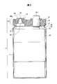
- FIG. 1 shows a capacitor according to an embodiment of the present invention.
- the capacitor shown in FIG. 1 is an example of the capacitor of the present invention, and the present invention is not limited to such a configuration.
- the capacitor 2 may be any capacitor that generates gas during driving, such as an electric double layer capacitor or an electrolytic capacitor.
- the outer case 4 of the capacitor 2 is sealed with a sealing plate 6.
- the sealing plate 6 is an example of a sealing member that seals the exterior case 4.
- the outer case 4 is, for example, an aluminum molded body.
- the sealing plate 6 may be any member that seals the exterior case 4 and is made of rubber or synthetic resin.
- the sealing plate 6 as an example is a molded product of a hard synthetic resin. Since the opening of the outer case 4 is circular, the sealing plate 6 is also formed in a circle according to the opening.
- a sealing ring 8 is installed on the peripheral edge of the sealing plate 6.
- a curling portion 10 is formed at the opening edge of the outer case 4.
- the curling portion 10 is an example of a sealing processing portion of the outer case 4.
- the outer case 4 is sealed with a sealing plate 6, a sealing ring 8, and a curling portion 10 of the outer case 4.
- the exposed surface portion 12 of the sealing plate 6 is surrounded by a curling portion 10.
- Island portions 14 and 16 are formed on the exposed surface portion 12.
- the island part 14 is an example of a terminal installation part.
- the island part 16 is an example of a valve installation part.
- An anode terminal 18-1 and a cathode terminal 18-2 are installed on the island portion 14.
- a pressure valve 20 is installed in the island portion 16.
- the island portion 14 includes a circular portion that circulates separately the anode terminal 18-1 and the cathode terminal 18-2. That is, the island portion 14 includes island portions 14-1 and 14-2, the island portion 14-1 includes a circular portion that circulates around the anode terminal 18-1, and the island portion 14-2 circulates around the cathode terminal 18-2. It has a circular part.
- the island part 14 has a symmetrical shape.
- the island portion 16 is formed at a position on the center line between the anode terminal 18-1 and the cathode terminal 18-2.
- a through hole 22 is formed in the center of the island portion 16.
- the through hole 22 is a circular hole that penetrates the sealing plate 6 in the thickness direction.
- a thin film portion 24 of the pressure valve 20 is installed in the through hole 22, and the thin film portion 24 protrudes from the through hole 22.
- the pressure valve 20 is made of rubber, for example.
- the material for forming the pressure valve 20 may be any material that provides a gas discharge function that accompanies an increase in the internal pressure of the outer case 4 and an explosion-proof function that breaks the thin film portion 24 when the internal pressure suddenly increases.
- a saturated rubber may be used as a material for forming the thin film portion 24.
- the saturated rubber include silicon rubber, butyl rubber, halogenated butyl rubber, vinyl-modified butyl rubber, ethylene propylene rubber, fluorine rubber, acrylic rubber, and hydrogenated nitrile rubber.
- a cross-linking agent, a filler, a plasticizer, an antiaging agent, or the like may be appropriately blended with the saturated rubber.
- the island part 16 is larger in diameter than the thin film part 24.
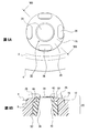
- a plurality of protrusions 26 are formed on the top of the island portion 16. In this embodiment, as an example, protrusions 26 are formed at four locations on the top of the island 16. Two protrusions 26 are formed in the central axis direction of the sealing plate 6. Two protrusions 26 are formed in a direction orthogonal to the central axis passing through these protrusions 26. That is, the thin film portion 24 of the pressure valve 20 is surrounded by the plurality of protrusions 26 and is opened in the side surface direction of the island portion 16 by the gaps 28 generated between the protrusions 26.
- the number of protrusions 26 may be less than 4 or 5 or more.
- the exposed surface portion 12 of the sealing plate 6 including the island portions 14 and 16 is a flat surface. That is, the island portions 14 and 16 formed on the flat surface are surrounded by the circular curling portion 10.
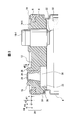
- FIG. 2 shows a cross section taken along line II-II in FIG.
- a capacitor element 30 is accommodated in the outer case 4.
- the capacitor element 30 is an electric double layer capacitor element if the capacitor 2 is an electric double layer capacitor or an electrolytic capacitor element if it is an electrolytic capacitor.
- the capacitor element 30 is an electric double layer capacitor, a columnar shape in which a separator is disposed and wound between polarizable electrode bodies in which polarizable electrode layers containing activated carbon are formed on both surfaces of a current collector such as aluminum. This is a winding element impregnated with an electrolytic solution.
- the capacitor element 30 is an electrolytic capacitor, it is a columnar element body wound with a separator interposed between an anode foil and a cathode foil, and is a wound element impregnated with an electrolytic solution.
- an internal lead portion 32 led out from one polarizable electrode body of the capacitor element 30 is connected to the anode terminal 18-1.
- an internal lead portion led out from the other polarizable electrode body of the capacitor element 30 is connected to the cathode terminal 18-2.
- an internal lead portion 32 led out from the anode foil of the capacitor element 30 is connected to the anode terminal 18-1.
- an internal lead portion derived from the cathode foil of the capacitor element 30 is connected to the cathode terminal 18-2.
- the outer case 4 has a step 34 for positioning and fixing the sealing plate 6.
- the step 34 is formed by caulking the outer case 4.
- a step portion 36 of the sealing plate 6 is engaged with the step portion 34.
- FIG. 3 shows the sealing plate 6 installed in the outer case 4.
- H1 ⁇ H2 ⁇ H3 ⁇ H4 may be preferable, and H1 ⁇ H2 ⁇ H3 ⁇ H4 may be more preferable.
- the island portions 14 (island portions 14-1) and 16 are integrally formed with the sealing plate 6 by, for example, synthetic resin molding.
- the height H2 of the island portion 14 (island portion 14-1) may be equal to the height H1 of the curling portion 10 or may be set higher than the curling portion 10. The same applies to the island portion 14-2 (not shown).
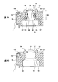
- FIG. 4A shows an enlarged cross section of the IVA buttock in FIG. 4B illustrates the pressure valve 20 from A in FIG.
- the pressure valve 20 includes the thin film portion 24 described above at the top.
- the thin film portion 24 is formed on the top of the main body portion 38.
- a flange portion 40 is formed around the thin film portion 24.
- the through hole 22 of the sealing plate 6 is closed by the thin film portion 24 and the flange portion 40.
- a pressure receiving hole 42 is formed at the center of the main body 38.
- the pressure receiving hole 42 has a small diameter portion 44 on the thin film portion 24 side and a large diameter portion 46 on the opening side.
- the inner side of the pressure valve 20 is inclined so that the hole diameter becomes smaller toward the thin film portion 24, and the pressure receiving hole 42 is formed in a truncated cone shape.
- An insertion portion 50 is formed on a side surface portion of the main body portion 38 with a fitting recess 48 sandwiched between the flange portion 40 side.
- the insertion portion 50 is larger in diameter than the fitting recess 48 and larger in diameter than the flange portion 40.
- a truncated cone-shaped stopper portion 52 is formed which increases in diameter toward the rear.
- a surface portion of the main body portion 38 facing the flange portion 40 of the insertion portion 50 also constitutes a stopper of the main body portion 38.
- a fitting protrusion 54 is formed in the through hole 22.
- the fitting protrusion 54 is sandwiched between the fitting recesses 48 of the pressure valve 20.
- the fitting protrusion 54 protrudes in the center direction of the through hole 22 and constitutes the smallest diameter portion of the through hole 22.
- the sealing plate 6 is formed with a fitting portion 56, a taper portion 58, and an opening portion 60 from the exposed surface portion 12 toward the back surface direction.
- the fitting portion 56 constitutes an insertion portion into which the insertion portion 50 of the pressure valve 20 is inserted.
- the inner diameter of the fitting portion 56 only needs to be large enough to be mounted using the elastic contractility of the pressure valve 20 in order to fix the insertion portion 50 of the pressure valve 20.
- the tapered portion 58 is a mounting portion of the stopper portion 52 and has the same or similar shape as the outer shape of the stopper portion 52.
- the opening 60 is an opening opened in the outer case 4 in order to guide the increase in internal pressure in the outer case 4 to the pressure receiving hole 42.
- an increase in internal pressure in the outer case 4 due to the gas generated by driving the capacitor element 30 acts on the thin film portion 24 from the open portion 60 through the pressure receiving hole 42. If the increase in internal pressure is less than the yield strength of the thin film portion 24, the gas is gradually discharged from the thin film portion 24. Thereby, the internal pressure of the exterior case 4 is maintained at an appropriate pressure by the pressure valve 20.
- the gas generated from the capacitor element 30 becomes prominent. Thereby, the internal pressure in the exterior case 4 rises abnormally.
- the increase in internal pressure acting on the thin film portion 24 exceeds the yield strength of the thin film portion 24, the thin film portion 24 is broken, thereby opening the pressure valve 20 and releasing the gas in the outer case 4 to the outside air. Thereby, the explosion-proof function of the capacitor 2 is fulfilled.
- the manufacturing method of the capacitor 2 includes a process of forming the island portion 16 and a process of installing the pressure valve 20.
- the sealing plate 6 having the above-described island portion 16 is formed.
- the height of the island part 16 is set to a height equal to or higher than the height of the curling part 10 (sealing part) formed in the outer case 4.
- the thin film part 24 which is the valve function part of the pressure valve 20 installed in the through hole 22 opened in the island part 16 of the outer case 4 is set to a position higher than the height of the curling part 10.
- Such a capacitor 2 or a manufacturing method thereof has the following characteristics, functions, or modifications.
- the soot pressure valve 20 is installed on the island 16 of the sealing plate 6. That is, the height of the island portion 16 is equal to or higher than the height of the curling portion 10. For this reason, even if dust or moisture adheres to the thin film portion 24 of the pressure valve 20 in the island portion 16 protruding beyond the height of the curling portion 10, the residue thereof can be reduced. As a result, a stable valve function can be maintained without impairing the valve function due to dust or moisture, and a reliable capacitor 2 can be obtained.
- the island portion 16 or the thin film portion 24 of the pressure valve 20 is set at a position higher than the top of the curling portion 10 of the outer casing 4. For this reason, even if moisture adheres to the exposed surface portion 12 of the sealing plate 6 surrounded by the curling portion 10 and remains, it does not reach the island portion 16 or the thin film portion 24 of the pressure valve 20. That is, the moisture in the surrounding part of the curling part 10 spills or evaporates without reaching the island part 16 or the thin film part 24 of the pressure valve 20.
- a plurality of protrusions 26 are provided on the top of the island 16. Thereby, the thin film part 24 of the pressure valve 20 arrange
- a gap 28 is formed between the plurality of protrusions 26.
- the water adhering to the top of the island part 16 flows down from the gap 28 and does not stay between the protrusions 26. That is, moisture remaining in the thin film portion 24 of the pressure valve 20 can be reduced, and deterioration of the valve function can be prevented.
- the outer peripheral part of the island 16 may be provided with a tapered surface or a curved surface projecting outside. With such a configuration, adhesion and retention of moisture to the thin film portion 24 of the pressure valve 20 are suppressed.
- the cocoon island part 16 By the cocoon island part 16, the space part and the surface part where dust and moisture are expected to remain can be removed from the sealing plate 6. Further, the submergence of the thin film portion 24 can be prevented. Furthermore, the thin film part 24 installed in the island part 16 is protected by the protrusions 26, and the thin film part 24 can be protected from the occurrence of damage during transfer.
- the thin film portion 24 of the pressure valve 20 has a flat surface shape, but as shown in FIG. But the form which the thin film part 24 bulges outside by the internal pressure rise may be sufficient. As shown in FIG. 5B, a tapered shape that descends to the periphery may be used. Further, the peripheral portion of the flange portion 40 may form a tapered surface 62 as shown in FIG. With such a configuration, adhesion of dust and moisture to the thin film portion 24 can be suppressed.
- the pressure valve 20 is installed on the sealing plate 6, but the present invention is not limited to this.
- the sealing member may be a part of an exterior member that encloses a capacitor element other than the sealing plate 6.
- the island portion 16 has a flat surface shape, whereas the island portion 16 faces the outer edge as shown in the VIB-VIB line cross section of FIG. 6A shown in FIG.
- the inclined surface may be a surface inclined downward, and may be a tapered surface or a curved surface. With such a configuration, water droplets flow toward the outer edge and are easily spilled from the island part 16, and dust moves toward the outer edge and easily falls from the island part 16. The function of reducing retention of water droplets and dust is enhanced.
- the pressure valve or the valve function part thereof is disposed at a position higher than the height of the sealing part of the outer case, adhesion of dust and moisture is suppressed, and a stable valve function is maintained. It can be useful.
- Capacitor 4 Exterior Case 6 Sealing Plate 8 Sealing Ring 10 Curling Portion 12 Exposed Surface Portion 14, 14-1, 14-2, 16 Island Portion 18-1 Anode Terminal 18-2 Cathode Terminal 20 Pressure Valve 22 Through Hole 24 Thin Film Portion 26 Protruding portion 28 Clearance 30 Capacitor element 32 Internal lead portion 34 Step portion 36 Step portion 38 Body portion 40 Flange portion 42 Pressure receiving hole 44 Small diameter portion 46 Large diameter portion 48 Fitting recess 50 Insertion portion 52 Stopper portion 54 Fitting protrusion 56 Fitting part 58 Taper part 60 Open part 62 Tapered surface
Landscapes
- Engineering & Computer Science (AREA)
- Power Engineering (AREA)
- Microelectronics & Electronic Packaging (AREA)
- Electric Double-Layer Capacitors Or The Like (AREA)
- Gas Exhaust Devices For Batteries (AREA)
Abstract
Description
4 外装ケース
6 封口板
8 封止環
10 カーリング部
12 露出面部
14、14-1、14-2、16 アイランド部
18-1 陽極端子
18-2 陰極端子
20 圧力弁
22 貫通孔
24 薄膜部
26 突部
28 隙間
30 コンデンサ素子
32 内部リード部
34 段部
36 段部
38 本体部
40 フランジ部
42 受圧孔
44 径小部
46 径大部
48 嵌合凹部
50 挿入部
52 ストッパ部
54 嵌合突部
56 嵌合部
58 テーパ部
60 開放部
62 テーパ面
Claims (6)
- コンデンサ素子を収納する外装ケースの封止加工部の高さ以上の高さを持つ弁設置部を備える封口部材と、
前記弁設置部の貫通孔に設置され、前記封止加工部の高さを超える位置に弁機能部が設定された圧力弁とを備えている、コンデンサ。 - 前記弁設置部の頂部に形成され、前記弁機能部を包囲する単一または複数の突部を備える、
請求項1に記載のコンデンサ。 - 前記封口部材は、前記封止加工部の高さ位置以上の高さに設定された端子設置部を備え、前記弁設置部は前記端子設置部の高さ以上の高さである、
請求項1または2に記載のコンデンサ。 - 前記弁機能部の外周部にテーパ面または、外部に張り出す曲面を備える、
請求項1ないし3のいずれか1項に記載のコンデンサ。 - 前記弁設置部が外縁に向かって傾斜する傾斜面を備える、
請求項1ないし4のいずれか1項に記載のコンデンサ。 - コンデンサ素子を収納する外装ケースを封口する外装ケースの封止加工部の高さ以上の高さを持つ弁設置部を形成し、
前記外装ケースの前記弁設置部に開口された貫通孔に設置する圧力弁の弁機能部を前記封止加工部の高さ以上の位置に設定する、
コンデンサの製造方法。
Priority Applications (5)
| Application Number | Priority Date | Filing Date | Title |
|---|---|---|---|
| CN201280055454.8A CN103946939B (zh) | 2011-11-17 | 2012-11-16 | 电容器及其制造方法 |
| KR1020147015947A KR102017357B1 (ko) | 2011-11-17 | 2012-11-16 | 콘덴서 및 그 제조 방법 |
| EP12850143.4A EP2782109B1 (en) | 2011-11-17 | 2012-11-16 | Capacitor and method for manufacturing same |
| JP2013544141A JP6136931B2 (ja) | 2011-11-17 | 2012-11-16 | コンデンサ |
| US14/269,309 US9437368B2 (en) | 2011-11-17 | 2014-05-05 | Capacitor and method for manufacturing same |
Applications Claiming Priority (2)
| Application Number | Priority Date | Filing Date | Title |
|---|---|---|---|
| JP2011251667 | 2011-11-17 | ||
| JP2011-251667 | 2011-11-17 |
Related Child Applications (1)
| Application Number | Title | Priority Date | Filing Date |
|---|---|---|---|
| US14/269,309 Continuation US9437368B2 (en) | 2011-11-17 | 2014-05-05 | Capacitor and method for manufacturing same |
Publications (1)
| Publication Number | Publication Date |
|---|---|
| WO2013073192A1 true WO2013073192A1 (ja) | 2013-05-23 |
Family
ID=48429285
Family Applications (1)
| Application Number | Title | Priority Date | Filing Date |
|---|---|---|---|
| PCT/JP2012/007353 Ceased WO2013073192A1 (ja) | 2011-11-17 | 2012-11-16 | コンデンサおよびその製造方法 |
Country Status (6)
| Country | Link |
|---|---|
| US (1) | US9437368B2 (ja) |
| EP (1) | EP2782109B1 (ja) |
| JP (1) | JP6136931B2 (ja) |
| KR (1) | KR102017357B1 (ja) |
| CN (1) | CN103946939B (ja) |
| WO (1) | WO2013073192A1 (ja) |
Cited By (4)
| Publication number | Priority date | Publication date | Assignee | Title |
|---|---|---|---|---|
| CN104576039A (zh) * | 2013-10-21 | 2015-04-29 | 丹阳市米可汽车零部件厂 | 压力自适应电容器 |
| JP2022509421A (ja) * | 2018-10-31 | 2022-01-20 | ティーディーケイ・エレクトロニクス・アクチェンゲゼルシャフト | キャパシタ |
| JPWO2022163210A1 (ja) * | 2021-02-01 | 2022-08-04 | ||
| US12283436B2 (en) * | 2020-10-30 | 2025-04-22 | Panasonic Intellectual Property Management Co., Ltd. | Power storage device, and method for manufacturing power storage device |
Families Citing this family (5)
| Publication number | Priority date | Publication date | Assignee | Title |
|---|---|---|---|---|
| WO2017069010A1 (ja) * | 2015-10-21 | 2017-04-27 | ニチコン株式会社 | 圧力弁及び電解コンデンサ |
| KR102565795B1 (ko) * | 2017-12-20 | 2023-08-09 | 닛뽄 케미콘 가부시끼가이샤 | 밀봉판, 콘덴서 및 밀봉판의 제조 방법 |
| DE102019133565A1 (de) * | 2019-12-09 | 2021-06-10 | Tdk Electronics Ag | Elektrolytkondensator mit Kontrollelement zur Gasdiffusion |
| CN213393710U (zh) * | 2020-07-14 | 2021-06-08 | 东莞东阳光科研发有限公司 | 泄压阀及具有其的电解电容器 |
| KR102686968B1 (ko) * | 2023-01-20 | 2024-07-22 | 성남전기공업(주) | 디스크를 가지는 콘덴서용 봉구재 |
Citations (5)
| Publication number | Priority date | Publication date | Assignee | Title |
|---|---|---|---|---|
| JPS4980333U (ja) * | 1972-10-31 | 1974-07-11 | ||
| JPS5520247U (ja) * | 1978-07-24 | 1980-02-08 | ||
| JPH03110827U (ja) | 1990-02-28 | 1991-11-13 | ||
| JP2000228180A (ja) * | 1999-02-04 | 2000-08-15 | Toyota Motor Corp | 二次電池 |
| JP2005116955A (ja) * | 2003-10-10 | 2005-04-28 | Nichicon Corp | コンデンサ |
Family Cites Families (14)
| Publication number | Priority date | Publication date | Assignee | Title |
|---|---|---|---|---|
| US2500632A (en) * | 1946-12-28 | 1950-03-14 | Bell Telephone Labor Inc | Electrolytic device |
| FR1344908A (fr) * | 1962-07-03 | 1963-12-06 | Yardney International Corp | Dispositif de valve uni-directionnelle applicable en particulier aux boîtiers d'accumulateurs électriques |
| US3874047A (en) | 1972-11-21 | 1975-04-01 | Allied Chem | Process to provide narrow yarn width of transfer tails of multifilament yarn |
| JPS5520247A (en) | 1978-07-31 | 1980-02-13 | Nippon Zeon Co | Soil culture material |
| US4992910A (en) * | 1989-11-06 | 1991-02-12 | The Evans Findings Company, Inc. | Electrical component package |
| JPH05291092A (ja) * | 1992-04-14 | 1993-11-05 | Nippon Chemicon Corp | 電解コンデンサ |
| JPH11145015A (ja) * | 1997-11-12 | 1999-05-28 | Matsushita Electric Ind Co Ltd | 電気二重層コンデンサ |
| JP2004190802A (ja) * | 2002-12-12 | 2004-07-08 | Kokoku Intech Co Ltd | 圧力調整弁、およびそれを備えたキャパシタ |
| JP2006135070A (ja) | 2004-11-05 | 2006-05-25 | Nichicon Corp | 圧力弁を有する封口板およびそれを用いた電子部品 |
| JP2006294669A (ja) * | 2005-04-06 | 2006-10-26 | Nok Corp | 圧力開放弁 |
| WO2007013500A1 (ja) * | 2005-07-26 | 2007-02-01 | Matsushita Electric Industrial Co., Ltd. | コンデンサ |
| EP2075809A4 (en) * | 2006-10-16 | 2014-09-17 | Panasonic Corp | CAPACITOR |
| KR100919106B1 (ko) * | 2008-02-04 | 2009-09-28 | 엘에스엠트론 주식회사 | 에너지 저장장치 |
| JP5380985B2 (ja) * | 2008-09-30 | 2014-01-08 | パナソニック株式会社 | キャパシタの製造方法及びキャパシタ |
-
2012
- 2012-11-16 CN CN201280055454.8A patent/CN103946939B/zh active Active
- 2012-11-16 JP JP2013544141A patent/JP6136931B2/ja active Active
- 2012-11-16 WO PCT/JP2012/007353 patent/WO2013073192A1/ja not_active Ceased
- 2012-11-16 KR KR1020147015947A patent/KR102017357B1/ko active Active
- 2012-11-16 EP EP12850143.4A patent/EP2782109B1/en active Active
-
2014
- 2014-05-05 US US14/269,309 patent/US9437368B2/en active Active
Patent Citations (5)
| Publication number | Priority date | Publication date | Assignee | Title |
|---|---|---|---|---|
| JPS4980333U (ja) * | 1972-10-31 | 1974-07-11 | ||
| JPS5520247U (ja) * | 1978-07-24 | 1980-02-08 | ||
| JPH03110827U (ja) | 1990-02-28 | 1991-11-13 | ||
| JP2000228180A (ja) * | 1999-02-04 | 2000-08-15 | Toyota Motor Corp | 二次電池 |
| JP2005116955A (ja) * | 2003-10-10 | 2005-04-28 | Nichicon Corp | コンデンサ |
Cited By (8)
| Publication number | Priority date | Publication date | Assignee | Title |
|---|---|---|---|---|
| CN104576039A (zh) * | 2013-10-21 | 2015-04-29 | 丹阳市米可汽车零部件厂 | 压力自适应电容器 |
| JP2022509421A (ja) * | 2018-10-31 | 2022-01-20 | ティーディーケイ・エレクトロニクス・アクチェンゲゼルシャフト | キャパシタ |
| US11501925B2 (en) | 2018-10-31 | 2022-11-15 | Tdk Electronics Ag | Capacitor |
| US12283436B2 (en) * | 2020-10-30 | 2025-04-22 | Panasonic Intellectual Property Management Co., Ltd. | Power storage device, and method for manufacturing power storage device |
| JPWO2022163210A1 (ja) * | 2021-02-01 | 2022-08-04 | ||
| WO2022163210A1 (ja) * | 2021-02-01 | 2022-08-04 | パナソニックIpマネジメント株式会社 | 蓄電デバイス |
| US12462987B2 (en) | 2021-02-01 | 2025-11-04 | Panasonic Intellectual Property Management Co., Ltd. | Power storage device |
| JP7821981B2 (ja) | 2021-02-01 | 2026-03-02 | パナソニックIpマネジメント株式会社 | 蓄電デバイス |
Also Published As
| Publication number | Publication date |
|---|---|
| KR102017357B1 (ko) | 2019-09-02 |
| US20140240900A1 (en) | 2014-08-28 |
| JP6136931B2 (ja) | 2017-05-31 |
| US9437368B2 (en) | 2016-09-06 |
| KR20140091593A (ko) | 2014-07-21 |
| EP2782109B1 (en) | 2018-06-13 |
| EP2782109A1 (en) | 2014-09-24 |
| EP2782109A4 (en) | 2015-10-07 |
| CN103946939B (zh) | 2017-02-15 |
| CN103946939A (zh) | 2014-07-23 |
| JPWO2013073192A1 (ja) | 2015-04-02 |
Similar Documents
| Publication | Publication Date | Title |
|---|---|---|
| JP6136931B2 (ja) | コンデンサ | |
| CN1610799A (zh) | 压力释放阀 | |
| EP3508776B1 (en) | Ventilation member and inspection method | |
| JP5713789B2 (ja) | ファスナ、航空機組立品、航空機組立品の製造方法、および治具 | |
| KR20150027734A (ko) | 전해 콘덴서용 압력 밸브 및 이를 이용한 전해 콘덴서 | |
| JP7741242B2 (ja) | 電解コンデンサにおけるコンデンサ素子に膜を固定する方法 | |
| JPWO2019124435A1 (ja) | 封口板、コンデンサおよび封口板の製造方法 | |
| CN1615553A (zh) | 用于电池的密封和排出阀单元 | |
| JP6489124B2 (ja) | コンデンサ | |
| JP2006324178A (ja) | 二次電池 | |
| CN210196413U (zh) | 一种重力压紧的单向通气塞 | |
| CN108717963A (zh) | 阀组件、盖组件、二次电池以及电池模组 | |
| US12025200B2 (en) | Method for sealing liquid composite spring | |
| JP2006294290A (ja) | 鉛蓄電池 | |
| JP5773487B2 (ja) | 空気弁 | |
| JP2006108185A (ja) | 電解コンデンサ | |
| CN101852418B (zh) | 一种压力平衡装置及使用该压力平衡装置的灯具 | |
| JP4887649B2 (ja) | 制御弁式鉛蓄電池 | |
| CN211314812U (zh) | 汽车控制室盖板的密封机构 | |
| JP2010034244A (ja) | 圧力開放弁 | |
| JP2014127692A (ja) | コンデンサおよびその封口板 | |
| JP2011119313A (ja) | 圧力開放弁 | |
| JP2020102541A (ja) | 圧力開放弁 | |
| CN206513735U (zh) | 一种离合器壳体 | |
| JP2010109272A (ja) | 圧力開放弁 |
Legal Events
| Date | Code | Title | Description |
|---|---|---|---|
| 121 | Ep: the epo has been informed by wipo that ep was designated in this application |
Ref document number: 12850143 Country of ref document: EP Kind code of ref document: A1 |
|
| ENP | Entry into the national phase |
Ref document number: 2013544141 Country of ref document: JP Kind code of ref document: A |
|
| WWE | Wipo information: entry into national phase |
Ref document number: 2012850143 Country of ref document: EP |
|
| NENP | Non-entry into the national phase |
Ref country code: DE |
|
| ENP | Entry into the national phase |
Ref document number: 20147015947 Country of ref document: KR Kind code of ref document: A |