METHOD AND SYSTEM FOR CONTROLLING VIBRATIONS IN A
DRILLING SYSTEM
The present invention relates to a method and to a system for controlling vibrations in a drilling system.
Numerous vibrations can occur in an elongate body extending into a borehole formed in a subsurface
formation, such as in a drill string operated to drill the borehole for the production of hydrocarbon fluid from the subsurface formation.
Drilling of an oil or gas wellbore is typically done by rotary drilling. Herein the wellbore may include vertical sections and/or sections deviating from
vertical, e.g. horizontal sections. Rotary drilling generally employs a drill string including a drill bit at its downhole end. The drill string typically includes drill pipe sections which are mutually connected by threaded couplings. In operation, a drive system located at or near surface may provide torque to the drill string to rotate the drill string to extend the borehole. The drive system may include, for example, a top drive or a rotary table. The drill string transmits the rotational motion to the drill bit. Generally the drill string also provides weight on bit and may transmit drilling fluid to the drill bit.
As a drill string may be several kilometres long, e.g. exceeding 5 or 10 km, the drill string may have a very large length to diameter ratio. As a result, the drill string behaves as a rotational spring and can be twisted several turns during drilling. Different modes of vibration may occur during drilling, e.g. rotational,
lateral and/or longitudinal (axial) vibrations, possibly causing alternating slip-stick motions of the drill string or the drill bit relative to the borehole wall. Such vibrations are due to, for example, fluctuating bit- rock interactions and pressure pulses in the drilling fluid generated by the mud pumps.
In a model description, a drill string can often be regarded as a torsional pendulum wherein the top of the drill string rotates with a substantially constant angular velocity, whereas the drill bit performs a rotation with varying angular velocity. The varying angular velocity can have a constant part and a
superimposed torsional vibration part. In extreme cases, the bit periodically comes to a complete standstill.
Maintaining rotation of the drill string at surface builds up torque and eventually causes the drill bit to come loose and to suddenly rotate again, typically leading to a downhole angular velocity being much higher than the angular velocity at surface, typically more than twice the speed of the nominal speed of the motor at surface, e.g. a top drive or rotary table. The downhole angular velocity is dampened again whereafter the process is repeated, causing an oscillating behaviour of the lower part of the drill string. This phenomenon is known as stick-slip.
It is desirable to reduce or prevent these vibrations in order to reduce one or more of shock loads to the drilling equipment, excessive bit wear, premature tool failures and relatively poor drilling rate. High peak speeds occurring during the slip phase can lead to secondary effects like extreme axial and lateral
accelerations and forces. Proper handling of downhole
vibrations can significantly increase reliability of the drilling equipment.
To suppress the stick-slip phenomenon, control methods and systems have been applied in the art to control the speed of the drive system such that the rotational speed variations of the drill bit are dampened or prevented.
One such method and system is disclosed in
EP-B-443689, whereby the energy flow through the drive system of the drilling assembly is controlled to be between selected limits, the energy flow being definable as the product of an across-variable and a through- variable. The speed fluctuations are reduced by measuring at least one of the variables and adjusting the other variable in response to the measurement.
In EP-B-1114240 it is pointed out that the control system disclosed in EP-B-443689 can be represented by a combination of a rotational spring and a rotational damper associated with the drive system. To obtain optimal damping, the spring constant of the spring and the damping constant of the damper are to be tuned to optimal values, whereby the rotational stiffness of the drill string plays an important role in tuning to such optimal values. To aid this tuning, EP-B-1114240
discloses a method and system for determining the
rotational stiffness of a drill string for drilling of a borehole in an earth formation.
WO 2010/063982 discloses a method and system for dampening stick-slip operations, wherein the rotational speed is controlled using a PI controller that is tuned such that the drilling mechanism absorbs torsional energy at or near the stick-slip frequency. The method can also comprise the step of estimating a bit speed, which is the
instantaneous rotational speed of a bottom-hole assembly. The bit speed is displayed at a driller's graphical interface and is regarded as a useful optional feature to help the driller visualize what is happening downhole.
A basic control theory for a non-smooth mechanical systems is described in A. Doris, Output-feedback design for non-smooth mechanical systems: Control synthesis and experiments, Ph.D. thesis, Eindhoven University of
Technology, September 2007 (hereinafter referred to as the Doris publication) .
The Doris publication uses a dynamic rotor system, including an upper disc connected to the motor (the top drive) and a lower disc connected to the bit. Inputs to the model are the angular position (phase) and the speed (first derivative of the phase) of both the upper disc and the lower disc. For the model to provide accurate results, the speed and phase of the lower disc will have to be measured using a downhole sensor.
Jens Rudat ET AL : "Development of an innovative model-based stick/slip control system", SPE/IADC Drilling
Conference and Exhibition, 139996, 1 March 2011,
discloses a system using surface measured rotary speed Ω and hook load H as inputs to both the real drilling process and to a model thereof. The output of the model ymr comprising downhole rotary speed CO, weight-on-bit W and torque on bit T, is compared to the measured output vector y of the drilling process. The comparison is used to adapt parameters of the model to the real drilling system. The model ifself however remains the same.
Disadvantage of the system is the requirement to measure downhole. As disclosed in Rudat et al . , in the bottom hole assembly a dynamics measurement tool was positioned close to the bit enabling the measurement of
the downhole parameters downhole rotary speed CO, weight- on-bit W and torque on bit T. The model parameters related to the measured values have to be transmitted to surface, using limited bandwidth telemetry systems.
US-2009/229882 discloses a system for active
vibration damping which relies on downhole sensors to measure motions of the drill string.
In practice, it is difficult to accurately measure the angular position and speed of the downhole disc, i.e. typically the drill bit. For instance, measurement of angular position and rotational speed may for instance be measured using a two-dimensional gravity sensor. During a slip-phase, wherein the bit suddenly accelerates from a complete standstill to a rotational speed exceeding the speed of the top drive, the phase accuracy is often lost.
And not knowing the exact angular position will render further output of the model inaccurate. Herein, please note that data transmission rates between a downhole location and surface, using currently available
techniques, are very low, typically less than 1 Hz. These low transmission rates allow for instance only one sample per 15 seconds or less.
In addition, the exact initial angular position of the drill bit is not known, which implies there is always an uncertainty or error in the measurement of the angular displacement of the bit. Since the drill string system is a non-linear system, for instance due to the friction, and exhibits multiple steady state solutions for the same excitation input, this error can drive the system in one or the other solution. A steady state solution, for instance, is constant rotational velocity at the top drive and stick-slip behaviour at the bit. Another steady state solution, for instance, is constant rotational
velocity at the top drive and at the bit. Again, this is also due to the low data transmission rate as explained above .
The known methods and systems assume a specific frequency of stick-slip oscillations (vibrations), and tune the control system to that effect. Such control strategy is inadequate in case the stick-slip vibrations occur at a different frequency than the expected
frequency, or when there are multiple vibration
frequencies which may change with operating conditions.
There is a need for an improved method of controlling vibrations in a drilling system, which overcomes the drawbacks of the prior art.
In accordance with the invention there is provided a method of controlling vibrations in a drilling system, the drilling system including an elongate body extending from surface into a borehole formed in an earth formation and a drive system for rotating the elongate body by providing a drive torque to the elongate body, the method comprising:
a) operating the drive system to provide a drive torque to the elongate body, and determining a system parameter that relates to an uphole parameter of the drilling system;
b) obtaining a model of the drilling system;
c) applying the model to determine a modeled system parameter that corresponds to said system parameter;
d) determining a difference between the system parameter and the modeled system parameter;
e) updating the model in dependence of said
difference, thereby obtaining an updated model;
f) determining from the updated model at least one modeled parameter of rotational motion, and adjusting the
drive torque in dependence of each modeled parameter of rotational motion so as to control vibrations of the elongate body.
The invention also relates to a control system for controlling vibrations in a drilling system, the drilling system including an elongate body extending from surface into a borehole formed in an earth formation and a drive system for rotating the elongate body by providing a drive torque to the elongate body, the control system comprising:
an operating device for operating the drilling system to provide a drive torque to the elongate body, and for determining a system parameter that relates to an uphole parameter of the drilling system;
- a model of the drilling system; and
computer means for applying the model to determine a modeled system parameter that corresponds to said system parameter, for determining a difference between the system parameter and the modeled system parameter, for updating the model in dependence of said difference thereby obtaining an updated model, for determining from the updated model at least one modeled parameter of rotational motion, and for adjusting the drive torque in dependence of each modeled parameter of rotational motion so as to control vibrations of the elongate body.
By using a model that predicts the responses of the drilling system, e.g. displacement, angular velocity, acceleration, frictional torque between drill string and rock formation, it is achieved that stick-slip vibrations of the drill string are eliminated for a range of angular velocities from angular velocities close to zero up to very high angular velocities. Furthermore, by updating the
model in dependence of a difference between the system parameter and the modeled system parameter, it is achieved that the parameters of the model converge rapidly to the parameters of the real drilling system so that the model accurately represents the state of the real drilling system. Also, with the method and control system of the invention, a constructive approach is used to adjust the drive torque delivered to the drill string so that there is no need for trial-and-error approach that can be time consuming. The model can include high system modes as many as required to simulate the drilling system accurately for the control purposes. It is robust in terms of model inaccuracies due to changes in the interaction between the rock formation and the drill bit or the drill string (frictional changes, damping changes, etc) . The controller provides information to the drive system to adjust the drive torque in order to avoid undesirable drill string vibrations. The adjusted drive torque results in a winding/unwinding of the drill string able to eliminate the stick-slip vibrations of the bottom-hole assembly .
Suitable, said uphole parameter of the drilling system relates to an uphole torque in the drilling system. An example of a parameter related to uphole torque can be a torque parameter provided by a rotary drive coupled to an uphole end of the elongate body, for example as available in modern top drives. Alternatively or in addition a parameter related to uphole torque can be a torque parameter, such as torque, measured at an uphole position of the elongate body.
For example, said uphole parameter of the drilling system suitably relates to torque (T) in the elongate body at or near the earth's surface.
In one embodiment, said model of the drilling system includes a modelled torsional stiffness (kem) of the elongate body, and wherein said drilling parameter comprises a ratio of said torque (T) over said modelled torsional stiffness (k6m) .
Suitably, said modeled system parameter relates to a modeled difference between an uphole rotational position of the elongate body and a downhole rotational position of the elongate body.
In one embodiment, said uphole parameter of the drilling system is a first uphole parameter, and wherein step (c) comprises applying the model using an input parameter relating to a second uphole parameter of the drilling system.
Suitably, the drive system comprises a rotary drive coupled to an uphole end of the elongate body, and wherein said second uphole parameter is or comprises torque (Tm) provided by the rotary drive to said uphole end of the elongate body.
To accurately model the drilling system, the model suitably includes at least one modeled state parameter and wherein step (e) comprises adding to each modeled state parameter the product of said difference and a respective gain factor pertaining to the modeled state parameter.
In one embodiment, each modeled state parameter relates to a modeled parameter of rotational motion of the elongate body.
Suitably, said at least one modeled state parameter is selected from a modeled difference between an uphole angular velocity and a downhole angular velocity of the elongate body, a modeled uphole angular acceleration of
the elongate body, and a modeled downhole angular
acceleration of the elongate body.
In one embodiment, step (b) comprises obtaining a state observer in which the model is included, the state observer further including a gain module for calculating each said gain factor.
Suitably, said at least one modeled parameter of rotational motion includes at least one of a modeled difference between an uphole rotational position and a downhole rotational position of the elongate body, a modeled uphole angular velocity of the elongate body, and a modeled downhole angular velocity of the elongate body.
The term "uphole" may refer to locations within, for example, 200 m from the earth surface or from a drilling rig used in the method of the invention. In case of an offshore operation, the earth surface is formed by the seabed. The term "downhole" may refer to locations within, for example, 200 m from the lower end of the elongate body. Suitably, the elongate body comprises a drill string having a drill bit at its downhole end.
The invention will be described hereinafter in more detail by way of example, with reference to the drawings, in which:
Figure 1 schematically shows a drilling system to be controlled by a preferred embodiment of the method and control system of the invention;
Figure 2A schematically shows an embodiment of the control system in modular form;
Figure 2B shows a schematic representation of an embodiment of the control system of the invention;
Figures 3a, 3b, 3c, 4a, 4b and 4c schematically show various results achieved using the method and control system of the invention.
In the description, like reference numerals relate to like components.
Fig. 1 shows a drilling system 1 including a drill string 2 extending from surface into a borehole (not shown) formed in an earth formation. The drill string 2 can be several thousand meters in length, and therefore behaves as a torsional spring. A drive system 4 is arranged at surface to rotate the drill string 2 in the borehole by providing a drive torque to the drill string 2. The drive system generally includes a motor arranged to drive a rotary table or a top drive (not shown) . The drill string 2 typically includes a downhole end part 6. Said downhole end part may include a bottom hole assembly (BHA) 6 including a drill collar having an increased weight which provides the necessary weight on bit during drilling. Top drive may imply a drive system which rotates an upper end of the drill string. Upper end implies the end at surface, i.e. near the location where the drill string is suspended from a drilling rig.
Reference sign 7 represents torque resistance Tu of the upper part of the drill string, e.g. due to
electrostatic forces in the motor, friction in the ball bearings, etc. Reference sign 8 represents torque
resistance Tt of the lower part of the drill string due to interaction of the BHA with the rock formation and the drilling mud.
The following parameters are used in the discussion below :
Tm : drive torque provided by the drive system 4 to the drill string 2;
V: voltage input to a motor (not shown) of the drive system 4;
Γ: torque in the drill string 2 as determined at or near the earth surface;
u: an update value for controlling drive torque;
ΘΗ , θι : rotational position of the drill string 2 at respective uphole and downhole locations;
0U , θι : rotational velocity of the drill string 2 at respective uphole and downhole locations;
0U , θι : rotational acceleration of the drill string 2 at respective uphole and downhole locations;
θα , θα , θα : model estimates of respective parameters
θα, θι , θι , θι : observer estimates of respective parameters θα, θι , θι , θι ;
&ueq ' 9leq=0eq equilibrium values of 0U and 0t ;
^ueq,eieq: equilibrium values of ¾ and θν
Furthermore, arrow 9 (Fig. 1) refers to the parameters ΘΗ , ΘΗ , ΘΗ , arrow 10 refers to the parameter Tm , and arrow
12 refers to the parameters θι , θι , θι .
Generally, the subscript "u" ("upper") refers to an uphole position, preferably at or near the surface of the earth, and the subscript "1" refers to a downhole
position, preferably at or near the downhole end of the elongate body. A bar above a symbol indicates a modelled parameter. A dot above a symbol refers to a single time derivative, i.e. a single dot indicates a velocity, and a double dot indicates acceleration. A "hat" above a symbol
(such as θ{) refers to a parameter of a state observer.
The subscript "eq" refers to an equilibrium value, that is a value for a state in which the system is free of
vibrations. When the system is in equilibrium, the bit
will generally rotate at the same frequency as the drill string at the connection to the motor. Angular velocity is also referred to as rotational velocity.
Uphole parameters of the drilling system 1 are determined at or near surface for use in the method of the invention. At or near surface implies that accurate measurements can be obtained using high-frequency sensors. High-frequency is for instance exceeding 1 kHz, i.e. more than 1000 samples per second. One such uphole parameter relates to uphole torque Γ in the upper part of the drill string 2. In the practice of the invention, the torque Tm applied in a modern drive system or a parameter directly related to Tm is often available as a digital parameter. Generally Γ differs slightly from Tm due to, for example, friction in the drive system itself and/or higher-frequency contributions that may not be transmitted between the drive system and the drill string. In case the drive system 4 includes a rotary table, such difference also can be due to transmission losses. In any event, uphole torque Γ or a parameter directly related to Γ can be determined for example by measuring, e.g. by a torque sensor at a location at or near the earth surface. Further uphole parameters can be measured by suitable sensors.
Uphole rotary velocity 0U or a related parameter may also be measured by a sensor at or near surface. Such related parameter is for example a period of one rotation of the drill string 2 at an uphole position. The period of rotation is directly related to and representative of angular velocity.
Fig. 2A shows a block diagram of a control system for controlling vibrations in the drilling system 1. The control system comprises a state observer 14 for
providing an estimate of the state of the drilling system
1. The state observer 14 may use measurements of the input and the output of the drilling system 1. The state observer 14 includes a mathematical model 16 of the drilling system and a gain module 18 for updating the model 16. The gain module may use input and output measurements of the drilling system 1. The model 16 may typically be implemented in a computer system running software, e.g. written in Matlab. It is known in the art how to build a model for a given drill string, and for the drill string in the borehole. The model 16 can be a simple two degree-of-freedom (DOF) model, e.g. similar to the one used in section 6.2.2. of the Doris publication. The model can also be a more complex multi degree-of- freedom model. It is also possible to derive a two degree- of-freedom model from a multi degree-of-freedom model using model reduction techniques known per se . The skilled person knows how to build a model that describes the dynamics of a specific drilling system accurately enough for the controller needs, by including sufficient eigen- modes of the drilling system. The control system further comprises a controller 20 arranged to control a motor 22 that drives the drill string 2.
The state observer 14 may receive an input signal 24 representing Tm. In practice, said motor torque Tm is available to the driller, as it may be derived from the current drawn by the top drive. Input signal 24 may also include Γ. The model 16 provides output signals 28, 30, 32 representing respective parameters θα, 9l , 9l . θα, are supplied to both the gain module 18 and the controller 20. θι is supplied to the controller 20. The controller 20 also receives an input signal 34 representing parameter 6U and an input signal 36 representing parameters
Θ ,6U -θι . Furthermore, reference sign 38 represents voltage V supplied to motor 22, reference sign 40
represents drive torque Tm supplied by motor 22 to drill string 2, and reference sign 42 represents a gain vector L supplied by gain module 18 to model 16.
During normal use of the drilling system 1, voltage V is supplied to the motor 22 and as a result the motor produces torque Tm that drives the drill string 2 in rotation. Γ and are measured at surface. T may be input to the observer. The observer output comprises θιι,θιΆηάθι.
These parameters together with 0U and 0eq , Θ - θι are input to the controller where they are multiplied by a
controller gain. The controller output is -u which is input back into the motor. The motor adapts Tm by -u and supplies the adjusted torque to the drill string 2.
A more detailed description of the way in which the observer 14, the model 16 and the controller 20 are used, is presented below.
The equations of motions of the drilling system 1 are governed by two inertias Ju,Jt , a spring flexibility ke , two frictional torques Tfu, Tfl , and torque input from the motor Tm . Ju is rotational inertia of the top drive and part of the drill string, J1 is rotational inertia of the Bottom-Hole-Assembly (BHA) and the remaining part of the drill-pipe. ke is rotational stiffness of the drill string. represents torque resistance in torsional motion of the upper part of the drill string (e.g.
electrostatic forces in the motor, friction in the ball bearings, etc.) and Tfl represents frictional interaction of the BHA with the formation and the drilling mud. The
differential equations that describe the torsional dynamics of this system are given in formulas (l)-(8) :
Ju-eu +ke -(0u -0l) + Tfii(eu)-Tm =O
J
l -0
l -k
e-(e
tt-e
i) + T
fl(0
l) = O
0
u =
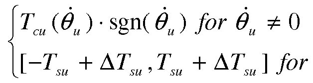
Tcu(eu) = Tsu +ATsu -sgn(0u) + bl θ,, + Ab„
[-Td,T fore, = 0
Τι(θι) = Τι +(Τι -Τ1) - β ^ + b, 'θ, (8) wherein :
Tcu < Tsu < Tsu r K , Abu , Tcl , Td , bt are constant parameters governed by frictional torque in the upper part of the drill string, such as in the drive system, and in the Bottom-Hole-Assembly. Example values of these parameters are presented in Table 1 at the end of this section. The torque Γ in the drill string 2 at or near surface is:
T = ke-(0tt-0,) .
The torque Γ can be derived from the current in the motor 22, and in practice it is always available to the drill-string operator.
Equations (9), (10) below are a copy of equations (1), (2) however with some disturbances included in the
parameters ke , Ju , Jt , Tfu and Tfl . These disturbances are used to simulate modelling inaccuracies when deriving a model for an oil-field drilling system. This set of equations (called: model of the drilling system) will be used to build the observer shown in the cascade of Figure 2A.
•/um A+^-(0„-^)+^J-^ = o (9)
Jlm- -k^-(0u-ei) + Tflm( l) = O (10)
where , J
um ,
T
flm are model values of respective parameters k
e , J
u, J
l,T
fu,T
fl . T
fum and T
flm have the same structure as T
fu and T
fl respectively. The parameters of the frictional forces of the model that are different from those of the drilling system are T
sum (instead of
Tsu ) r m (instead of bu) , Tdm (instead of Tcl) and
blm (instead ofbt) .
In state-space form the dynamics of the drilling system can be written as:
where xl= θιι-θι , x2 = θα and x3 = 0t .
In state-space form the dynamics of the model of the drilling system can be written as:
JC^ — "^ , "^3
%. = -J—l-kan Xl - Tfum<¾) + T
where xl = θιι-θι , x2 = ΘΗ and χ3=θι .
In state-space form the observer is represented by the following expression:
T
θτη
where li r l2 and l3 are observer gains and x2 = θα and χ3=θι. The gain vector L \- r ^2 r ^3 ] ·
By applying the observer design techniques disclosed in Chapters 5 and 6 of the Doris publication, the values
Ιγ, l2, l3 can be computed. The goal of the observer is to derive estimates of the drilling system states that are as close as possible to the real drill-string system's states. To derive the observer gains lx, l2, Z3 , a set of linear matrix inequalities (LMIs) is to be solved, for example using the software Matlab and in particular the Matlab toolbox LMI-tool. The procedure to derive these LMIs is described in the Doris publication.
In a further step, an adjustment to the drive torque is applied for torque control so as to control
vibrations. The adjustment takes the following form in this example:
■[0 -0,-(0 -Θ, )]-£,■[0 -0 ) - ·[θ, (14) where the subscript eq refers herein to equilibrium values of the model and the drill-string system. The adjustment u to the drive torque is calculated using modelled downhole parameters of rotational motion. and 0leqare equal to each other, as these are the desired values of the drilling system while drilling because no stick-slip vibrations occur when they are equal. Hence the bit will
rotate at the same rotational speed as the drill string at the connection to the drive system.
In order to calculate 0ueq,0leq , the acceleration component in equations (9), (10) is nullified (i.e.
,
eq = A,
eq = 0 ) , substitutions 0
U =0
ueq =0^, =0
leq =0
eq are performed, and equations (9), (10) are solved: kem
' (^u.eq - fy .eq) +
Tfum (^eq ) ~
Tm = ^ so that:
)
Herein, {dueq-0leq) is constant. Formulas (9) and (10) may be used to derive either (0U eq - θι eq) , i.e. the output of the model 16 or (#„,<¾- , i.e. the output of the
observer 14. Also, {dueq-0leq) may be derived. Regarding the latter, optionally a measured value for 0ueq may be included, for instance provided by sensor 54. In formula (14), kl,k2,k3 are constants calculated according to the control theory of the Doris publication using the model (9), (10). Example values of these parameters are
presented in Table 1.
Formula (14) provides a correction factor to the torque. The corrected torque Tc applied to the drill string, after the adjustment, is for instance:
T =T -u
This torque is then substituted in equation (1) replacing T
Fig. 2B shows a schematic flow scheme, representing the above described control system of the invention in an alternative form.
A driller 50 operates a drilling rig (not shown) comprising the drive system 22. The driller 50 sets the voltage input V by signal 38 to the drive system 22. In response to the voltage signal 38, the drive system 22 will try to rotate the drill string 2 of the drilling system 1 at a reference rotation Qref .
Thus, the reference rotation Qref is set by the driller, by signal 38. When the drill string system would rotate in equilibrium, the equilibrium rotary speed at surface Θ and downhole would be equal to the set reference rotation Qref :
@u,eq = l,eq = ^ref
These values are therefore readily available, and may be provided for instance by the drive system 22, see signal 52.
To rotate the drill string, the drive system 22 provides a motor torque Tm to the drilling system 1. In response to the received motor torque Tm, the drill string and drill bit of the drilling system 1 will rotate. A resulting output vector y may include rotary position and rotary speed both at surface and downhole. However, in the system of the invention, downhole components of the output vector y of the drilling system may be disregarded. Only one or more uphole components, which can be accurately measured, are required. Downhole measurements are
obviated .
It is for instance sufficient to measure the rotary speed <¾ =
at the connection between the drive system and the drilling system, for instance using sensor 54. Sensor 54 may be a separate module, or may be included in the drive system 22. Said surface rotary speed <¾ =
may be provided to the controller 20. See signal 34.
A measured torque value, for instance the motor torque Tm, may be provided to the model 16 and to the model gain module 18. See signals 24.
In response to receiving the motor torque Tm, the model provides a model output vector ym. Said model output vector ym may comprise angular position and rotary speed both at surface and downhole respectively.
The signal 52 may also comprise the value of (θίι-θι), which is available due to the relation thereof to the torque Γ in the drill string 2 at or near surface:
The torque Γ can be derived from the current in the drive system 22. In practice the value T is available to the operator 50. Otherwise, T can be measured accurately at or near the connection between the drive system 22 and the drill string 2.
When the drilling system rotates in equilibrium or stead state, the above also provides:
The value of (0U eq— θ1 eq ) may thus be derived from the torque value when the drilling system operates at
equilibrium.
The value (θίί-θι) may be provided to the control module 20 via signal 52. Alternatively, the contol module 20 may calculate the value (θίι-θ1) using the torque T as provided by the drive system.
The model module 16 may be provided with any suitable model of the drilling system 1. Using the input signal 24, which comprises the motor torque Tm, the model module provides the model output vector ym.
The model output vector ym comprises for instance the modelled rotary positions θη,θι at surface and downhole respectively. Also, ym may comprise modelled downhole rotary speed θι=ύ)1ηι . Herein, 0)lm and θι are both
representations of the modelled downhole rotary speed.
The modelled rotary positions θι,,θι at surface and downhole respectively may be provided to a model gain module 18. See signal 56. The model gain module 18 calculates the gain vector L = [lir l2, l3 ] , as described above relating to Formula (13) . The model gain module provides the gain vector L to the model module 16. See signal 58. The model module 16 uses the gain vector L to improve the parameters of the model, and consequently to improve the output vector ym.
The values of θα,θι,ω1ηι as provided by the model module
16, which preferably have been adjusted and improved using the input of the gain module 18, are provided to control module 20. See signal 60.
The control module 20 uses the available inputs
(included in signals 34, 52, and 60) in formula (14) to provide a torque correction factor u: u = -k,■ [¾ - 0t - {0u≠q - 0eq)] - k2 ■ [¾ - dum)] - *3 ■ - q ]
Until the drilling system is in equilibrium, and given the available inputs, said formula can also be written as: u = -kl-[du-dl-{^)]-k2-[ u-aref)]-ki-[ lm-aref]
Kg
The torque correction factor u is provided to the drive system 22, which substracts said factor u from the motor torque Tm, to arrive at a corrected torque value Tc:
Tc =Tm -U
The corrected torque Tc is then substituted in equation (1) replacing Tm.
Herein, please note that the reference frequency Qref as set by the driller 50 is not affected by the above correction. Rather, the correction is applied to adjust the torque that the drive system applies to the drill string to arrive at said ΩΓβ£ .
Reference is further made to Figs. 3a-c showing results for the drill string 2, the model 16 and the observer 14, whereby the controller 20 is de-activated in order to illustrate convergence of the drill string states as determined by the model 16 and the observer 14 to the real drill string states. Fig. 3a shows = θιι-θι as a function of time t. Fig. 3b shows <¾ = 9U as a function of time t. Fig. 3c shows <¾ = θι as a function of time t.
These figures indicate that the drilling system's state as determined by the observer 16 rapidly converges to the drilling system's real state.
Reference is further made to Figs. 4a-c showing results whereby the controller 20 is activated. Herein the control system operates in closed-loop with the drilling system so as to dampen stick-slip behaviour of the drill string 2. Fig. 4a shows = θιι—θι as a function of time t,
Fig. 4b shows ωπ =0U as a function of time t, and Fig. 4c
shows <¾ = 0j as a function of time t. These figures demonstrate that the control loop is able to rapidly eliminate the stick-slip behaviour of the drilling system Rapidly herein implies for instance in less than a minute
Example values of the various parameters discussed hereinbefore are presented in Table 1 below.
The present invention is not limited by the above- described embodiments thereof, wherein many modifications are conceivable within the scope of the appended claims . Features of respective embodiments may for instance be combined .