WO2013076801A1 - 音声信号補正装置及び音声信号補正方法 - Google Patents
音声信号補正装置及び音声信号補正方法 Download PDFInfo
- Publication number
- WO2013076801A1 WO2013076801A1 PCT/JP2011/076854 JP2011076854W WO2013076801A1 WO 2013076801 A1 WO2013076801 A1 WO 2013076801A1 JP 2011076854 W JP2011076854 W JP 2011076854W WO 2013076801 A1 WO2013076801 A1 WO 2013076801A1
- Authority
- WO
- WIPO (PCT)
- Prior art keywords
- period
- waveform
- audio signal
- unit
- prediction
- Prior art date
- Legal status (The legal status is an assumption and is not a legal conclusion. Google has not performed a legal analysis and makes no representation as to the accuracy of the status listed.)
- Ceased
Links
Images



Classifications
-
- H—ELECTRICITY
- H04—ELECTRIC COMMUNICATION TECHNIQUE
- H04B—TRANSMISSION
- H04B1/00—Details of transmission systems, not covered by a single one of groups H04B3/00 - H04B13/00; Details of transmission systems not characterised by the medium used for transmission
- H04B1/06—Receivers
- H04B1/10—Means associated with receiver for limiting or suppressing noise or interference
- H04B1/1027—Means associated with receiver for limiting or suppressing noise or interference assessing signal quality or detecting noise/interference for the received signal
-
- G—PHYSICS
- G10—MUSICAL INSTRUMENTS; ACOUSTICS
- G10L—SPEECH ANALYSIS TECHNIQUES OR SPEECH SYNTHESIS; SPEECH RECOGNITION; SPEECH OR VOICE PROCESSING TECHNIQUES; SPEECH OR AUDIO CODING OR DECODING
- G10L19/00—Speech or audio signals analysis-synthesis techniques for redundancy reduction, e.g. in vocoders; Coding or decoding of speech or audio signals, using source filter models or psychoacoustic analysis
- G10L19/005—Correction of errors induced by the transmission channel, if related to the coding algorithm
-
- H—ELECTRICITY
- H04—ELECTRIC COMMUNICATION TECHNIQUE
- H04H—BROADCAST COMMUNICATION
- H04H2201/00—Aspects of broadcast communication
- H04H2201/10—Aspects of broadcast communication characterised by the type of broadcast system
- H04H2201/13—Aspects of broadcast communication characterised by the type of broadcast system radio data system/radio broadcast data system [RDS/RBDS]
-
- H—ELECTRICITY
- H04—ELECTRIC COMMUNICATION TECHNIQUE
- H04H—BROADCAST COMMUNICATION
- H04H60/00—Arrangements for broadcast applications with a direct linking to broadcast information or broadcast space-time; Broadcast-related systems
- H04H60/09—Arrangements for device control with a direct linkage to broadcast information or to broadcast space-time; Arrangements for control of broadcast-related services
- H04H60/11—Arrangements for counter-measures when a portion of broadcast information is unavailable
Definitions
- the present invention relates to an audio signal correction device, an audio signal correction method, an audio signal correction program, and a recording medium on which the audio signal correction program is recorded.
- broadcast receivers that are mounted on a moving body such as a vehicle and receive radio broadcast waves have been widely used. Advances in technology related to such broadcast receivers are remarkable, and for example, a radio data system (RDS) implemented in Europe is put to practical use as an information transmission system for multiplex transmission of broadcast-related information using a part of a subcarrier of radio broadcast. It has become.
- RDS radio data system
- each broadcast station present in each reception area broadcasts a PS code indicating a broadcast station name (program service name) and the same program on a frequency-modulated FM audio signal that is the content of the broadcast program.
- RDS data having data such as an AF (Alternative Frequency) code indicating a broadcast station frequency list (alternative frequency list) for each networked reception area and a PI code for identifying a program is frequency-multiplexed and broadcast. is doing. Since such RDS data is a collection of code data specifying each broadcasting station, RDS data is extracted by detecting a broadcast wave (arrival radio wave) arriving at the broadcast receiving apparatus, and the extracted RDS data is used. By performing network follow processing, it is possible to automatically search for receivable broadcast stations and to switch the channel selection so that broadcast waves with better reception quality can be received. ing.
- Patent Document 1 A technique for suppressing the discontinuity of the reproduced sound due to the lack of the sound signal for reproduction due to the temporary interruption of the channel selection state has been proposed (see Patent Document 1; hereinafter referred to as “conventional example”). ).
- the audio signal for reproduction in the missing period is predicted based on the audio signal obtained directly from the selected broadcast wave in the period immediately before the missing period.
- the discontinuity in the audio signal for reproduction is between the period before the missing period and the missing period. Sex does not occur. However, discontinuity may occur in the audio signal for reproduction between the missing period and the period after the missing period, and abnormal sounds may occur in the reproduced audio.
- the present invention has been made in view of the above circumstances, and an object thereof is to provide an audio signal correction apparatus and an audio signal correction method for generating an output audio signal capable of suppressing discontinuity for a listener.
- the present invention is an audio signal correction apparatus that corrects an input audio signal including a missing period and generates a continuous output audio signal, over a predetermined time longer than the missing period.
- a buffer storage unit that stores the waveform of the input audio signal up to; a first waveform in a first period that is a period before the missing period in the buffer storage unit, and a period after the missing period
- a waveform prediction unit that calculates a predicted waveform in a waveform prediction period based on a second waveform of a second period; and the waveform prediction period based on the first waveform, the second waveform, and the calculated predicted waveform
- An output audio signal generation unit that generates the output audio signal at the same time, and the waveform prediction period overlaps the missing period, a first overlap period that overlaps the first period, and a second period.
- the output speech signal in the waveform prediction period is a waveform obtained by weighted averaging the waveform of the input speech signal and the predicted waveform in the first and second overlap periods. And a signal having the predicted waveform in a period other than the first and second overlapping periods.
- the present invention includes a buffer storage unit that stores a waveform of the input audio signal up to the present time over a predetermined time longer than a missing period of the input audio signal, and corrects the input audio signal.
- An audio signal correction method used in an audio signal correction apparatus that generates a continuous output audio signal, the first waveform of a first period being a period before the missing period in the buffer storage unit, and the A waveform prediction step of calculating a predicted waveform in a waveform prediction period based on a second waveform of a second period that is a period after the missing period; the first waveform, the second waveform, and the calculated predicted waveform
- an output audio signal generating step for generating the output audio signal in the waveform prediction period, wherein the waveform prediction period overlaps the missing period and the first period.
- the output audio signal in the waveform prediction period is a continuous period including an overlap period and a second overlap period that overlaps the second period.
- the output audio signal in the waveform prediction period is the same as the input audio signal in the first and second overlap periods.
- An audio signal correction method comprising: a waveform obtained by weighted averaging of a waveform and the predicted waveform; and a signal having the predicted waveform in a period other than the first and second overlapping periods.
- the present invention is an audio signal correction program characterized by causing an arithmetic unit to execute the audio signal correction method of the present invention.
- the present invention is a recording medium in which the audio signal correction program of the present invention is recorded so as to be readable by a calculation unit.
- FIG. 1 It is a figure which shows schematic structure of a broadcast receiver provided with the audio
- FIG. 4 is a flowchart for explaining output sound signal generation processing by the output sound signal generation unit of FIG. 3.
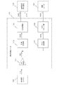
- FIG. 1 is a block diagram illustrating a configuration of an RDS-compatible broadcast receiving apparatus 100 including an audio signal correcting apparatus 140 according to an embodiment.
- the broadcast receiving apparatus 100 includes an antenna 110, an RF processing unit 120, a level detection unit (DET) 125, and a reproduction processing unit 130 in addition to the audio signal correction apparatus 140.
- the broadcast receiving apparatus 100 includes a sound output unit 150, an operation input unit 160, and a control unit 190.
- the antenna 110 receives broadcast waves from various broadcast stations (base stations). Then, the reception result by the antenna 110 is sent to the RF processing unit 120 as a reception signal RFS.
- the RF processing unit 120 receives the reception signal RFS transmitted from the antenna 110. Then, the RF processing unit 120 performs a channel selection process for extracting a reproduction channel signal from the reception signal RFS in accordance with a channel selection command CSL from the control unit 190, and generates a signal IFS having a predetermined intermediate frequency. The signal IFS generated in this way is sent to the DET 125 and the reproduction processing unit 130.
- the RF processing unit 120 includes an input filter, a high-frequency amplifier (RF AMP: Radio Frequency-Amplifier), and a band-pass filter (hereinafter also referred to as “RF filter”).
- the RF processing unit 120 includes a mixer (mixer), an intermediate frequency filter (hereinafter also referred to as “IF filter”), and a local oscillation circuit (OSC).
- mixer mixer
- IF filter intermediate frequency filter
- OSC local oscillation circuit
- the input filter is a high-pass filter that blocks low-frequency components of the reception signal RFS sent from the antenna 110.
- the high frequency amplifier amplifies the signal that has passed through the input filter.
- the RF filter selectively passes signals in a specific frequency range among signals output from the high frequency amplifier.
- the mixer mixes the signal that has passed through the RF filter and the local oscillation signal supplied from the local oscillation circuit.
- the IF filter selects and passes a signal in a predetermined intermediate frequency range among the signals output from the mixer.
- the local oscillation circuit includes an oscillator that can control the oscillation frequency by voltage control or the like. This local oscillation circuit generates a local oscillation signal having a frequency corresponding to the channel to be selected in the RF processing unit 120 in accordance with the channel selection command CSL supplied from the control unit 190, and supplies the local oscillation signal to the mixer.
- the DET 125 detects the signal level of the signal IFS sent from the RF processing unit 120. This detection result reflects the electric field strength of the broadcast wave of the reproduction channel in the vicinity of the antenna 110. A detection result by the DET 125 is sent to the control unit 190 as a detection result SLD.
- the reproduction processing unit 130 receives the signal IFS sent from the RF processing unit 120. Then, the reproduction processing unit 130 processes the signal IFS to generate an audio signal DAD and a strobe instruction STB that are digital signals. The audio signal DAD and the strobe instruction STB generated in this way are sent to the audio signal correction device 140. For this reason, the audio signal DAD is an input audio signal for the audio signal correction device 140.
- the audio signal correction device 140 receives the audio signal DAD and the strobe instruction STB sent from the reproduction processing unit 130. In addition, the audio signal correction device 140 receives the missing period instruction DPI sent from the control unit 190. Then, the audio signal correction device 140 generates an output audio signal AOD that is a digital signal based on the audio signal DAD, the strobe instruction STB, and the missing period instruction DPI. The output audio signal AOD generated in this way is sent to the sound output unit 150.
- the signal level of the missing period instruction DPI is “L (insignificant)” level. Become.
- the signal level of the missing period instruction DPI becomes the “H (significant)” level.
- the audio signal correction device 140 receives the operation control command RST sent from the control unit 190.
- the audio signal correction device 140 performs an initialization process described later, and then starts the audio signal correction process. Further, when receiving the operation control command RST designating the end of the operation, the audio signal correction device 140 ends the audio signal correction processing.
- the sound output unit 150 receives the output audio signal AOD sent from the audio signal correction device 140.
- the sound output unit 150 receives the volume control command VLC sent from the control unit 190. Then, the sound output unit 150 outputs sound corresponding to the output sound signal AOD at a sound volume specified by the sound volume control command VLC.
- the sound output unit 150 includes a DA (Digital-to-Analogue) conversion unit, an electronic volume unit, a power amplification unit, and a speaker.
- the DA converter receives the output sound signal AOD sent from the sound signal correction device 140. Then, the DA converter converts the output audio signal AOD into an analog signal, and sends the converted analog signal to the electronic volume unit.
- the electronic volume unit that has received the analog signal sent from the DA conversion unit adjusts the level of the analog signal in accordance with the volume control command VLC sent from the control unit 190, and uses the level-adjusted signal as a level adjustment signal.
- the power amplification unit that receives the level adjustment signal sent from the electronic volume unit performs power amplification of the level adjustment signal and sends it to the speaker as a power amplification signal. As a result, sound corresponding to the output sound signal AOD is output from the speaker.
- the operation input unit 160 is configured by a key unit provided in the main body of the broadcast receiving device 100 and / or a remote input device including the key unit.
- a key part provided in the main body a touch panel provided in a display unit (not shown) can be used.
- it can replace with the structure which has a key part, or can also employ
- the result of operation input to the operation input unit 160 is sent to the control unit 190 as operation input data IPD. By operating this operation input unit 160, the user can perform designation input such as reproduction channel designation and volume adjustment designation.
- the control unit 190 controls the overall operation of the broadcast receiving apparatus 100.
- the control unit 190 includes a timer and the like.
- the control unit 190 When the reproduction channel designation input to the operation input unit 160 is notified as the operation input data IPD, the control unit 190 generates a reproduction channel tuning command according to the reproduction channel designation. Then, the control unit 190 sends the generated channel selection designation as the channel selection command CSL to the RF processing unit 120, and sends the operation control command RST designating the operation start to the audio signal correction device 140.
- the control unit 190 sends an operation control command RST designating the operation end to the audio signal correction device 140, The entire operation of the broadcast receiving apparatus 100 is terminated.
- the control unit 190 when the output volume designation input to the operation input unit 160 is notified as the operation input data IPD, the control unit 190 generates a playback channel volume control designation according to the output volume designation. Then, the control unit 190 sends the generated volume control designation to the sound output unit 150 as a volume control command VLC.
- control unit 190 periodically performs an optimal station search during the reception processing period.
- the control unit 190 first generates a search channel selection command for at least one broadcast channel that broadcasts the same program as the program being reproduced, and uses the RF processing unit as the channel selection command CSL. Send to 120.
- the control unit 190 collects the detection results SLD by the DET 125 each time each search channel selection command is sent as the channel selection command CSL.
- control unit 190 determines the optimum channel based on the collection result of the detection result SLD by the DET 125. Then, the control unit 190 generates a channel selection command for the determined optimum channel and sends it to the RF processing unit 120 as the channel selection command CSL. Thereafter, the control unit 190 ends the optimum station search.
- the control unit 190 determines that the audio signal DAD related to the broadcast audio of the reproduction channel is missing, sets the missing period instruction DPI to the “H” level, and the missing period. It reports to the audio signal correction device 140 that it is in the middle.
- the control unit 190 determines that the audio signal DAD related to the broadcast audio of the reproduction channel is generated, and sets the missing period instruction DPI to the “L” level. Then, it reports to the audio signal correction device 140 that it is during the normal period.
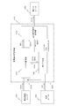
- the reproduction processing unit 130 includes an intermediate frequency amplifier (IF AMP) 131, an audio detection unit 132, and an AD (Analogue to Digital) conversion unit 133.
- the reproduction processing unit 130 includes an RDS detection unit 137 and an RDS decoding unit 138.
- the above intermediate frequency amplifier 131 receives the signal IFS sent from the RF processing unit 120. Then, the intermediate frequency amplifier 131 amplifies the signal IFS. The amplification result is sent as a signal AIS to the voice detection unit 132 and the RDS detection unit 137.
- the voice detector 132 receives the signal AIS sent from the intermediate frequency amplifier 131. Then, the sound detection unit 132 performs detection processing on the signal AIS by a predetermined method to generate a detection signal DAS. The detection signal DAS generated in this way is sent to the AD conversion unit 133.
- the AD converter 133 receives the detection signal DAS sent from the sound detector 132. Then, the AD conversion unit 133 converts the level value of the detection signal DAS into a digital signal at a predetermined sampling period. The digital signal thus converted is sent as an audio signal DAD to the audio signal correction device 140 together with a strobe instruction STB indicating that the new AD conversion result is output in synchronization with the output of the new AD conversion result. It is done. For this reason, by collecting the value of the audio signal DAD in synchronization with the strobe instruction STB, the audio signal correction device 140 obtains the AD conversion result of the level value of the detection signal DAS output in the predetermined sampling period. It is now possible to collect without fail.
- the RDS detection unit 137 receives the signal AIS sent from the intermediate frequency amplifier 131. Then, the RDS detection unit 137 performs detection processing on the signal AIS by a predetermined method including broadcast-related information, and generates a detection signal DRS. The generated detection signal DRS is sent to the RDS decoding unit 138.
- the RDS decoding unit 138 performs a decoding process on the detection signal DRS from the RDS detection unit 137 to generate RDS data RSD including broadcast related information.
- the RDS data RSD includes a program identification code (PI code), an AF code that is data of frequency information of a broadcast channel belonging to the same network as the current reproduction channel, and the like.
- PI code program identification code
- AF code AF code that is data of frequency information of a broadcast channel belonging to the same network as the current reproduction channel
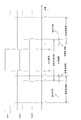
- the audio signal correction device 140 includes a buffer storage unit 141, a waveform prediction unit 142, and an output audio signal generation unit 143.
- the above-described buffer storage unit 141 includes an internal storage unit that stores data.
- the internal storage unit is a random access memory for the waveform prediction unit 142, and a FIFO (First-In First-Out) memory realized by a ring buffer configuration for the output audio signal generation unit 143. It is configured to be.
- FIFO First-In First-Out
- the buffer storage unit 141 receives the audio signal DAD and the strobe instruction STB sent from the reproduction processing unit 130. Then, the buffer storage unit 141 sequentially writes the data value supplied as the audio signal DAD to the internal storage unit at the synchronization timing indicated by the strobe instruction STB.
- the buffer storage unit 141 has a storage capacity capable of storing data supplied as the audio signal DAD over a period equal to or longer than the data period length required for waveform prediction processing by the waveform prediction unit 142 described later.
- the buffer storage unit 141 includes a known maximum period length of a waveform prediction period in which the waveform prediction unit 142 performs waveform prediction, and a period length that is predetermined as a period length of a later audio period that will be described later.
- the storage capacity is such that the data supplied as the audio signal DAD can be stored during the period of the sum of the two.
- the buffer storage unit 141 uses the oldest written data (hereinafter referred to as “oldest data”) among the data stored in the internal storage unit as data MOD to the output audio signal generation unit 143. To send. In addition, when the buffer storage unit 141 receives the reading report BDR sent from the output audio signal generation unit 143, the buffer storage unit 141 deletes the oldest data in the internal storage unit.
- the buffer storage unit 141 instructs the output audio signal generation unit 143 to provide a buffer full instruction BFL. Send.
- the buffer storage unit 141 sends to the waveform prediction unit 142 a buffer pointer BPA indicating the address of the internal storage unit in which the latest data is written. Further, when the buffer storage unit 141 receives the read signal RAR specifying the address of the internal storage unit, the buffer storage unit 141 sends the data stored at the specified address to the waveform prediction unit 142 as data BFD.
- the waveform prediction unit 142 receives the strobe instruction STB sent from the reproduction processing unit 130. In addition, the waveform prediction unit 142 receives the missing period instruction DPI sent from the control unit 190. Then, the waveform prediction unit 142 generates a waveform based on the storage capacity of the internal storage unit of the buffer storage unit 141, the data stored in the internal storage unit of the buffer storage unit 141, the strobe instruction STB, and the missing period instruction DPI. A prediction waveform in the prediction period is calculated. The time series data of the predicted waveform thus calculated is sent to the output audio signal generation unit 143 as the predicted waveform data PWD in synchronization with the output from the buffer storage unit 141 of the data MOD in the waveform prediction period.
- the predicted waveform data PWD is sent to the output audio signal generation unit 143 as predicted waveform information PWI integrated with a flag FLG indicating a period type to be described later.
- the predicted waveform calculation process by the waveform predicting unit 142 and the bit configuration of the predicted waveform information PWI will be described later.
- the output audio signal generation unit 143 receives the buffer full instruction BFL and data MOD sent from the buffer storage unit 141 and the predicted waveform information PWI sent from the waveform prediction unit 142. Here, the output audio signal generation unit 143 reads the data MOD and the predicted waveform information PWI every time the buffer full instruction BFL is received.
- the output audio signal generation unit 143 generates the output audio signal AOD based on the value of the data MOD and the predicted waveform information PWI every time the data MOD and the predicted waveform information PWI are read.
- the output audio signal AOD is generated by performing a weighted average of the value of the data MOD and the predicted waveform data PWD in the predicted waveform information PWI in a pre-overlapping period and a post-overlapping period described later.
- the output audio signal AOD generated in this way is sent to the sound output unit 150.
- the audio signal correction device 140 executes an initialization process. By executing this initialization process, all data stored in the internal storage of the buffer storage unit 141 is erased. Further, by executing the initialization process, the waveform prediction unit 142 stops the waveform prediction process so far and newly starts the waveform prediction process, and the output audio signal generation unit 143 outputs the output audio signal so far Is stopped, and output sound signal generation processing is newly started.
- a period related to the waveform prediction processing by the waveform prediction unit 142 will be described with reference to FIG.
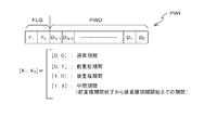
- the above-described missing period in which the audio signal DAD related to the broadcast audio of the reproduction channel is missing is a period from time T ⁇ 1 to time T 1 (> T ⁇ 1 ).
- the fact that it is a missing period is indicated by the missing period instruction DPI becoming “H” level as described above.
- the waveform prediction unit 142 is a period from the previous speech period (time T -4 ( ⁇ T -1 ) to time T -2 (T -4 ⁇ T -2 ⁇ T -1 ), which is a period before the missing period. ) Of waveform information corresponding to the audio signal DAD in the previous audio period (hereinafter referred to as “previous audio waveform information”). Further, the waveform predicting unit 142 is based on data related to the audio signal DAD in the subsequent audio period (the period from time T 2 ( ⁇ T 1 ) to time T 4 (> T 2 )), which is a period after the missing period. Thus, waveform information corresponding to the audio signal DAD in the subsequent audio period (hereinafter referred to as “post audio waveform information”) is calculated.
- the time T -2 is the time before the time T -1, time T 2, is in the after time T 1. This is because the audio signal DAD may not reflect the broadcast audio reliably immediately before and after the missing period.
- the waveform prediction unit 142 Information on the period length of the previous voice period and the period length of the subsequent voice period, the time interval between the missing period and the previous voice period, and the time interval between the missing period and the subsequent voice period are held in the waveform prediction unit 142. ing.
- the period length of the previous audio period and the period length of the subsequent audio period are the same length.
- the time interval between the missing period and the previous voice period and the time interval between the missing period and the subsequent voice period are the same.
- a period (a period from time T -2 to time T 2 ) between the previous speech period and the subsequent speech period in the waveform prediction period is referred to as an intermediate period.
- the waveform prediction unit 142 calculates a predicted waveform in the waveform prediction period.
- Such waveform forecast period from time T -3 (T -4 ⁇ T -3 ⁇ T -2), and has a period until time T 3 (T 2 ⁇ T 3 ⁇ T 4). Therefore, the waveform forecast period, in addition to the missing period described above, before the overlap period (first overlapping period) from the time T -3 to time T -2, and, after from time T 2, until time T 3 An overlapping period (second overlapping period) is included.
- the period length of the preceding overlapping period and the period length of the following overlapping period is held in the waveform prediction unit 142.
- the period length of the previous overlapping period and the period length of the subsequent overlapping period are the same.
- the signal level change timing of the above-described missing period instruction DPI, the reception status of the strobe instruction STB, and the inside of the waveform prediction unit 142 as described above are retained.
- Storage capacity of the internal storage unit of the buffer storage unit 141, information on the period length of the previous audio period and the period length of the subsequent audio period, the time interval between the missing period and the previous audio period, and the time between the missing period and the subsequent audio period Based on the interval, the period length of the previous overlapping period, and the period length of the subsequent overlapping period, the waveform predicting unit 142 determines that the data output from the buffer storage unit 141 includes the previous overlapping period, the subsequent overlapping period, and the previous overlapping period. It is possible to determine whether the data corresponds to a period between the subsequent overlapping periods.
- bit configuration of the predicted waveform information PWI will be described.
- the value of the flag FLG [F 1 , F 0 ] at each time is represented by the upper 2 bits, and at each time by the other bits.
- Values of the predicted waveform data PWD [D N ⁇ 1 , D N ⁇ 2 ,..., D 1 , D 0 ] are represented.
- Z (T) WNF (T) * N (T) + WPF (T) * P (T) (1)
- the weight W NF (T) linearly decreases from “1” to “0” in the previous overlap period. Also, the weight W PF (T) increases linearly from “0” to “1” in the previous overlap period.
- the output audio signal generation unit 143 sets the value weight of the data MOD as W NR (T) and the value weight of the predicted waveform data PWD as W PR (T), and the value N (T)
- Z (T) WNR (T) * N (T) + WPR (T) * P (T) (2)
- the weight W NR (T) increases linearly from “0” to “1” in the post-overlap period. Further, the weight W PR (T) is linearly decreased from “1” to “0” in the subsequent overlap period.
- the broadcast receiving apparatus 100 has started a broadcast receiving operation, and the control unit 190 has already sent an operation control command RST designating the start of operation to the audio signal correcting apparatus 140.
- the control unit 190 sets the reproduction channel for the RF processing unit 120 in accordance with the channel selection designation input to the operation input unit 160.
- the output volume is set for the sound output unit 150 in accordance with the output volume designation input to the operation input unit 160.
- the broadcast receiving apparatus 100 it is assumed that the audio signal DAD and the strobe instruction STB corresponding to the broadcast using the reproduction channel are supplied to the audio signal correcting apparatus 140 except for the optimum station search processing period. .
- an output audio signal AOD corresponding to broadcasting using the reproduction channel is supplied to the sound output unit 150.
- the optimum station search process is periodically executed.
- the control unit 190 changes the level of the missing period instruction DPI from “L” to “H”.
- the control unit 190 changes the level of the missing period instruction DPI from “H” to “L”.
- the audio signal correcting apparatus 140 includes a data buffering process by the buffer storage unit 141, a waveform prediction process and a synchronous output process by the waveform prediction unit 142, and an output audio signal generation unit.
- the output voice generation process according to 143 is executed.
- the buffer storage unit 141 sequentially writes the data value supplied as the audio signal DAD to the internal storage unit at the synchronization timing indicated by the strobe instruction STB. Then, the buffer storage unit 141 sends the oldest data in the internal storage unit to the output audio signal generation unit 143 as data MOD, and the waveform prediction unit 142 uses the buffer pointer BPA in the internal storage unit in which the latest data is written. Send to.
- the buffer storage unit 141 instructs the output audio signal generation unit 143 to provide a buffer full instruction BFL. Send.
- the buffer storage unit 141 receives the reading report BDR sent from the output audio signal generation unit 143, the buffer storage unit 141 erases the oldest data in the internal storage unit at that time.
- step S11 the waveform prediction unit 142 determines whether or not the missing period instruction DPI has changed from the “L” level to the “H” level. To determine whether the missing period has started. If the result of this determination is negative (step S11: N), the process of step S11 is repeated.
- step S11 the waveform prediction unit 142 calculates previous speech waveform information that is waveform information in the previous speech period with respect to the current missing period.
- the waveform prediction unit 142 In calculating the previous speech waveform information, the waveform prediction unit 142 first corresponds to the previous speech period in the internal storage unit of the buffer storage unit 141 based on the buffer pointer BPA sent from the buffer storage unit 141 at that time. Specify the data area to be used. Subsequently, the waveform prediction unit 142 reads data in the storage area specified this time.
- the waveform prediction unit 142 performs Fourier transform on the time waveform of the speech in the previous speech period based on the read data, and converts the amplitude spectrum (previous amplitude spectrum) and phase spectrum (previous phase spectrum) into the previous speech. Calculated as waveform information. And the waveform estimation part 142 hold
- step S13 the waveform prediction unit 142 determines whether or not the missing period has ended by determining whether or not the missing period instruction DPI has changed from the “H” level to the “L” level. If the result of this determination is negative (step S13: N), the process of step S13 is repeated.
- step S14 the waveform prediction unit 142 determines whether or not the post-speech period has ended.
- the waveform prediction unit 142 determines the number of strobe instructions STB periodically sent from the reproduction processing unit 130 after the missing period instruction DPI changes from the “H” level to the “L” level. By determining whether or not the number has been reached, it is determined whether or not the later audio period has ended.
- step S14 If the result of the determination in step S14 is negative (step S14: N), the process of step S14 is repeated. Then, when the post-audio period ends and the result of the determination in step S14 is affirmative (step S14: Y), the process proceeds to step S15.
- step S15 the waveform prediction unit 142 calculates post-speech waveform information that is waveform information in a post-speech period with respect to the current missing period.
- the waveform prediction unit 142 In calculating the post-speech waveform information, the waveform prediction unit 142 first determines the data in the post-speech period in the internal storage unit of the buffer storage unit 141 based on the buffer pointer BPA sent from the buffer storage unit 141 at that time. Specify the area. Subsequently, the waveform prediction unit 142 reads data in the storage area specified this time.
- the waveform prediction unit 142 performs Fourier transform on the time waveform of the speech in the subsequent speech period based on the read data, and converts the amplitude spectrum (rear amplitude spectrum) and the phase spectrum (rear phase spectrum) into the rear speech. Calculated as waveform information. And the waveform estimation part 142 hold
- the waveform prediction unit 142 calculates average waveform information.
- the waveform prediction unit 142 calculates an average amplitude spectrum that is an average of the front amplitude spectrum and the rear amplitude spectrum, and an average phase spectrum that is an average of the front phase spectrum and the rear phase spectrum. Calculated as average waveform information.
- step S17 the waveform prediction unit 142 performs an inverse Fourier transform on the average waveform information calculated this time to calculate a predicted waveform that is a time waveform in the current waveform prediction period. Then, the waveform predicting unit 142 holds the calculated predicted waveform data therein.
- step S11 when the calculation of the predicted waveform is completed, the process returns to step S11. Thereafter, the processes in steps S11 to S17 are repeated, and a predicted waveform in the waveform prediction period is calculated each time a missing period occurs.
- step S21 the waveform prediction unit 142 determines whether or not a new strobe instruction STB has been received. If the result of this determination is negative (step S21: N), the process of step S21 is repeated.
- step S21: Y When the new strobe instruction STB sent from the reproduction processing unit 130 is received and the result of the determination in step S21 is affirmative (step S21: Y), the process proceeds to step S22.
- step S22 the waveform prediction unit 142 determines whether the data MOD output from the buffer storage unit 141 is data in the normal period. If this determination result is affirmative (step S22: Y), the process proceeds to step S23.
- step S23 the waveform prediction unit 142 outputs the predicted waveform information PWI in which the flag FLG [F 1 , F 0 ] is the value [0, 0] and the value of the predicted waveform data PWD is indefinite, and the output audio signal generation unit 143. Send to. Then, the process returns to step S21.
- step S22 determines whether the data MOD output from the buffer storage unit 141 is data of the previous overlap period. If this determination result is affirmative (step S24: Y), the process proceeds to step S25.
- step S25 the waveform prediction unit 142 sets the flag FLG [F 1 , F 0 ] to the value [0, 1], and the value of the predicted waveform data PWD is set to the data MOD output from the buffer storage unit 141.
- the predicted waveform information PWI that is the value of the predicted waveform data corresponding thereto is sent to the output audio signal generation unit 143. Then, the process returns to step S21.
- step S24 determines whether the data MOD output from the buffer storage unit 141 is intermediate period data. If this determination result is affirmative (step S26: Y), the process proceeds to step S27.
- step S27 the waveform prediction unit 142 sets the flag FLG [F 1 , F 0 ] to the value [1, 1], and the value of the predicted waveform data PWD is set to the data MOD output from the buffer storage unit 141.
- the predicted waveform information PWI that is the value of the predicted waveform data corresponding thereto is sent to the output audio signal generation unit 143. Then, the process returns to step S21.
- step S26 If the result of the determination in step S26 is negative (step S26: N), the process proceeds to step S28.
- step S28 the waveform prediction unit 142 sets the flag FLG [F 1 , F 0 ] to the value [1, 0], and the value of the predicted waveform data PWD becomes the data MOD output from the buffer storage unit 141.
- Predicted waveform information PWI which is the value of predicted waveform data corresponding to the time, is sent to the output audio signal generation unit 143. Then, the process returns to step S21.
- steps S21 to S28 are repeated.
- the waveform prediction unit 142 sends the predicted waveform information PWI corresponding in time to the data MOD output from the buffer storage unit 141 to the output audio signal generation unit 143. .
- step S31 the output sound signal generation unit 143 determines whether or not a new buffer full instruction BFL has been received. If the result of this determination is negative (step S31: N), the process of step S31 is repeated.
- step S31 If the new buffer full instruction BFL sent from the buffer storage unit 141 is received and the result of the determination in step S31 is affirmative (step S31: Y), the process proceeds to step S32.
- step S32 the output audio signal generation unit 143 reads the data MOD sent from the buffer storage unit 141 and the predicted waveform information PWI sent from the waveform prediction unit 142.
- the output audio signal generation unit 143 sends the reading report BDR to the buffer storage unit 141.
- the buffer storage unit 141 erases the oldest data in the internal storage unit, and the buffer full state in the buffer storage unit 141 is released.
- step S33 the output audio signal generation unit 143 determines whether or not the value of the flag FLG [F 1 , F 0 ] in the read predicted waveform information PWI is [0, 0]. Then, it is determined whether or not data in the normal period has been read. If the result of this determination is affirmative (step S33: Y), the process proceeds to step S34.
- step S34 the output audio signal generation unit 143 uses the data MOD out of the read data MOD and the predicted waveform data PWD in the predicted waveform information PWI as output audio data, and sends the output audio signal AOD to the sound output unit 150. . Then, the process returns to step S31.
- step S33 determines whether or not the value of the read flag FLG [F 1 , F 0 ] is [0, 1], whereby the data in the previous overlap period is obtained. It is determined whether or not it has been read. If the result of this determination is affirmative (step S35: Y), the process proceeds to step S36.
- step S36 the output audio signal generation unit 143 has the read data MOD and predicted waveform data PWD and the value of the read flag FLG [F 1 , F 0 ] become [0, 1]. Based on the elapsed time from the start of the previous overlap period specified from the number of issued read reports BDR, the value (Z (T)) of the output audio data is calculated by the above-described equation (1). Then, the calculated value of the output audio data is sent to the sound output unit 150 as an output audio signal AOD. Thereafter, the process returns to step S31.
- step S35 determines whether or not the value of the read flag FLG [F 1 , F 0 ] is [1, 1], thereby reading the data in the intermediate period. It is determined whether or not it has been. If the result of this determination is affirmative (step S37: Y), the process proceeds to step S38.
- step S38 the output audio signal generation unit 143 sets the predicted waveform data PWD out of the read data MOD and the predicted waveform data PWD as output audio data, and sends the output audio signal AOD to the sound output unit 150. Then, the process returns to step S31.
- step S37 If the result of the determination in step S37 is negative (step S37: N), the process proceeds to step S39.
- step S39 after the output audio signal generation unit 143 has read the data MOD and the predicted waveform data PWD and the value of the read flag FLG [F 1 , F 0 ] becomes [1, 0].
- the value (Z (T)) of the output audio data is calculated by the above-described equation (2) based on the elapsed time from the start of the post-overlapping period specified from the number of read reports BDR issued. Then, the calculated value of the output audio data is sent to the sound output unit 150 as an output audio signal AOD. Thereafter, the process returns to step S31.
- steps S31 to S39 are repeated.
- a new data value is sent from the output audio signal generation unit 143 to the sound output unit 150 as the output audio signal AOD.
- the sound according to the output sound signal AOD corrected by the sound signal correction device 140 is output from the speaker of the sound output unit 150.
- the previous audio waveform that is the audio waveform in the previous audio period that is the period before the missing period in which the audio signal DAD related to the broadcast audio of the reproduction channel is missing
- the waveform prediction unit 142 calculates a predicted waveform in the waveform prediction period.
- the waveform prediction period is a continuous period including a missing period, a pre-overlapping period that overlaps the previous audio period, and a post-overlapping period that overlaps the subsequent audio period.
- the output voice signal generation unit 143 generates the output voice signal AOD in the waveform prediction period based on the previous voice waveform, the rear voice waveform, and the predicted waveform.
- the output audio signal AOD in the waveform prediction period has a waveform obtained by weighted averaging the waveform of the audio signal DAD and the prediction waveform in the pre-overlap period and the post-overlap period, and between the pre-overlap period and the post-overlap period.
- the output audio signal generation unit 143 generates the output audio signal AOD so that the signal has a predicted waveform in the intermediate period.
- an output audio signal that can suppress discontinuity for the listener can be generated.
- the waveform prediction unit 142 when calculating the predicted waveform, the waveform prediction unit 142 first performs Fourier transform on the previous speech waveform to calculate the previous amplitude spectrum and the previous phase spectrum, and Fourier transforms the subsequent speech waveform. Then, a post-amplitude spectrum and a post-phase spectrum are calculated. Subsequently, the waveform prediction unit 142 calculates an average amplitude spectrum of the previous amplitude spectrum and the rear amplitude spectrum, and an average phase spectrum of the previous phase spectrum and the rear phase spectrum. Then, the waveform prediction unit 142 performs inverse Fourier transform on the average amplitude spectrum and the average phase spectrum, and calculates the predicted waveform by digital calculation. For this reason, it is possible to rationally calculate the predicted waveform with a simple configuration.
- the interval is set between the missing period and the previous voice period, and between the missing period and the subsequent voice period.
- the previous voice period is set immediately before the missing period.
- a later audio period may be set immediately after the missing period.
- the weighted average is calculated using the linearly changing weight as shown in FIG.
- the weighted average may be calculated using a weight that changes in a curved manner.
- the audio signal is corrected in the waveform prediction period after the time sequential data output from the buffer storage unit.
- the same calculation as the audio signal correction calculation by the output audio signal generation unit in the above embodiment is performed before the time sequential data output from the buffer storage unit becomes the data output corresponding to the waveform prediction period.
- the data corresponding to the waveform prediction period in the puffer storage unit may be rewritten with the correction process result data.
- the audio signal correction apparatus of the present invention corrects the audio signal when the audio signal related to the broadcast audio of the reproduction channel in the optimum station search period occurs.
- the audio signal correction apparatus according to the present invention corrects the audio signal even when an audio signal related to the broadcast audio of the reproduction channel occurs when automatically searching for a receivable broadcast station. Also good.
- the broadcast receiving apparatus adopting the RDS system is provided with the audio signal correcting apparatus of the present invention.
- the broadcast receiving apparatus adopting the RDS system is used.
- other devices can be provided with the sound signal correcting device of the present invention.
- the audio signal correction apparatus in the above embodiment is configured as a computer as a calculation unit including a DSP (Digital Signal Processor) and the like, and a program prepared in advance is executed on the computer, whereby in the above embodiment. Some or all of the processing may be executed.
- This program is recorded on a computer-readable recording medium such as a hard disk, CD-ROM, or DVD, and is read from the recording medium and executed by the computer.
- the program may be acquired in a form recorded on a portable recording medium such as a CD-ROM or DVD, or may be acquired in a form distributed via a network such as the Internet. Also good.
Landscapes
- Engineering & Computer Science (AREA)
- Signal Processing (AREA)
- Physics & Mathematics (AREA)
- Health & Medical Sciences (AREA)
- Audiology, Speech & Language Pathology (AREA)
- Human Computer Interaction (AREA)
- Computational Linguistics (AREA)
- Acoustics & Sound (AREA)
- Multimedia (AREA)
- Computer Networks & Wireless Communication (AREA)
- Circuits Of Receivers In General (AREA)
- Two-Way Televisions, Distribution Of Moving Picture Or The Like (AREA)
- Arrangements For Transmission Of Measured Signals (AREA)
- Reverberation, Karaoke And Other Acoustics (AREA)
Abstract
音声信号DADが欠落している欠落期間よりも前の期間である前音声期間における前音声波形、及び、当該欠落期間よりも後の期間である後音声期間における後音声波形に基づいて、波形予測部142が、欠落期間と、前音声期間に重なる前重複期間と、後音声期間に重なる後重複期間とを含む連続した波形予測期間における予測波形を算出する。そして、出力音声信号生成部143が、前音声波形、後音声波形及び予測波形に基づいて、前重複期間及び後重複期間においては音声信号DADの波形と予測波形とを重み付け平均した波形を有し、前重複期間と後重複期間との間の中間期間においては予測波形を有する信号を、波形予測期間における出力音声信号AODとして生成する。この結果、聴取者にとっての不連続感を抑制することができる出力音声信号を生成することができる。
Description
本発明は、音声信号補正装置、音声信号補正方法及び音声信号補正プログラム、並びに、当該音声信号補正プログラムを記録した記録媒体に関する。
従来から、車両等の移動体に搭載され、ラジオ放送波を受信する放送受信装置が広く普及している。こうした放送受信装置に関する技術の進展は目覚しく、ラジオ放送の副搬送波の一部を用いて放送関連情報を多重伝送する情報伝送システムとして、例えば、欧州で実施されているラジオデータシステム(RDS)が実用化されている。
このRDSでは、受信エリアごとに存在する各々の放送局が、放送番組の内容である周波数変調したFMオーディオ信号に、放送局名(プログラムサービス名)を示すPSコード、同一番組を放送するためにネットワーク化されている受信エリアごとの放送局の周波数リスト(代替周波数のリスト)を示すAF(Alternative Frequencies)コード、番組を識別するためのPIコード等のデータを有するRDSデータを周波数多重して放送している。かかるRDSデータは、各放送局を特定するコードデータの集まりであることから、放送受信装置に到来する放送波(到来電波)を検波等してRDSデータを抽出し、その抽出したRDSデータを利用してネットワークフォローの処理を行うことで、受信可能な放送局を自動検索したり、より良好な受信品質の得られる放送波を受信するように選局切り替えを行ったりすることができるようになっている。
こうしたネットワークフォローの処理を1チューナ構成の放送受信装置で行う場合には、聴取用の選局を一時的に中断することが必要となる。こうした選局状態の一時的な中断による再生用の音声信号の欠落に起因する再生音声の不連続性を抑制するための技術が提案されている(特許文献1参照;以下、「従来例」という)。この従来例の技術では、欠落期間の直前の期間において選局放送波から直接的に得られる音声信号に基づいて、当該欠落期間における再生用の音声信号を予測するようにしている。
上述した従来例の技術では、欠落期間直前の音声信号に基づいて、欠落期間中の音声信号を予測するので、欠落期間前の期間と欠落期間との間では、再生用の音声信号における不連続性は発生しない。しかしながら、欠落期間と欠落期間後の期間との間では、再生用の音声信号における不連続性が発生することがあり、再生音声に異音が発生することがあった。
このため、ネットワークフォローの動作のために再生用の入力音声信号が途絶えてしまう場合であっても、欠落期間と欠落期間後の期間との間においても聴取者にとっての不連続感を抑制することができる音声再生用の出力音声信号を生成することができる技術が待望されている。かかる要請に応えることが、本発明が解決すべき課題の一つとして挙げられる。
本発明は、上記の事情に鑑みてなされたものであり、聴取者にとっての不連続感を抑制することができる出力音声信号を生成する音声信号補正装置及び音声信号補正方法を提供することを目的とする。
本発明は、第1の観点からすると、欠落期間を含む入力音声信号を補正して連続的な出力音声信号を生成する音声信号補正装置であって、前記欠落期間よりも長い所定時間にわたって、現時点までの前記入力音声信号の波形を記憶するバッファ記憶部と;前記バッファ記憶部内における前記欠落期間よりも前の期間である第1期間の第1波形、及び、前記欠落期間よりも後の期間である第2期間の第2波形に基づいて、波形予測期間における予測波形を算出する波形予測部と;前記第1波形、前記第2波形及び前記算出された予測波形に基づいて、前記波形予測期間における前記出力音声信号を生成する出力音声信号生成部と;を備え、前記波形予測期間は、前記欠落期間と、前記第1期間に重なる第1重複期間と、前記第2期間に重なる第2重複期間とを含む連続的な期間であり、前記波形予測期間における前記出力音声信号は、前記第1及び第2重複期間においては前記入力音声信号の波形と前記予測波形とを重み付け平均した波形を有し、前記第1及び第2重複期間以外の期間においては前記予測波形を有する信号である、ことを特徴とする音声信号補正装置である。
本発明は、第2の観点からすると、入力音声信号の欠落期間よりも長い所定時間にわたって、現時点までの前記入力音声信号の波形を記憶するバッファ記憶部を備え、前記入力音声信号を補正して連続的な出力音声信号を生成する音声信号補正装置で使用される音声信号補正方法あって、前記バッファ記憶部内における前記欠落期間よりも前の期間である第1期間の第1波形、及び、前記欠落期間よりも後の期間である第2期間の第2波形に基づいて、波形予測期間における予測波形を算出する波形予測工程と;前記第1波形、前記第2波形及び前記算出された予測波形に基づいて、前記波形予測期間における前記出力音声信号を生成する出力音声信号生成工程と;を備え、前記波形予測期間は、前記欠落期間と、前記第1期間に重なる第1重複期間と、前記第2期間に重なる第2重複期間とを含む連続的な期間であり、前記波形予測期間における前記出力音声信号は、前記第1及び第2重複期間においては前記入力音声信号の波形と前記予測波形とを重み付け平均した波形を有し、前記第1及び第2重複期間以外の期間においては前記予測波形を有する信号である、ことを特徴とする音声信号補正方法である。
本発明は、第3の観点からすると、本発明の音声信号補正方法を演算部に実行させる、ことを特徴とする音声信号補正プログラムである。
本発明は、第4の観点からすると、本発明の音声信号補正プログラムが、演算部により読み取り可能に記録されている、ことを特徴とする記録媒体である。
以下、本発明の一実施形態を、図1~図9を参照して説明する。なお、以下の説明及び図面においては、同一又は同等の要素には同一の符号を付し、重複する説明を省略する。
[構成]
図1には、一実施形態に係る音声信号補正装置140を備えるRDS対応の放送受信装置100の構成がブロック図にて示されている。この図1に示されるように、放送受信装置100は、音声信号補正装置140に加えて、アンテナ110と、RF処理ユニット120と、レベル検出部(DET)125と、再生処理ユニット130とを備えている。また、放送受信装置100は、音出力ユニット150と、操作入力ユニット160と、制御ユニット190とを備えている。
図1には、一実施形態に係る音声信号補正装置140を備えるRDS対応の放送受信装置100の構成がブロック図にて示されている。この図1に示されるように、放送受信装置100は、音声信号補正装置140に加えて、アンテナ110と、RF処理ユニット120と、レベル検出部(DET)125と、再生処理ユニット130とを備えている。また、放送受信装置100は、音出力ユニット150と、操作入力ユニット160と、制御ユニット190とを備えている。
上記のアンテナ110は、様々な放送局(基地局)からの放送波を受信する。そして、アンテナ110による受信結果は、受信信号RFSとして、RF処理ユニット120へ送られる。
上記のRF処理ユニット120は、アンテナ110から送られた受信信号RFSを受ける。そして、RF処理ユニット120は、制御ユニット190からの選局指令CSLに従って、再生チャンネルの信号を受信信号RFSから抽出する選局処理を行い、所定の中間周波数を有する信号IFSを生成する。こうして生成された信号IFSは、DET125及び再生処理ユニット130へ送られる。
ここで、RF処理ユニット120は、入力フィルタと、高周波増幅器(RF AMP:Radio Frequency-Amplifier)と、バンドパスフィルタ(以下、「RFフィルタ」とも呼ぶ)とを備えている。また、RF処理ユニット120は、ミキサ(混合器)と、中間周波フィルタ(以下、「IFフィルタ」とも呼ぶ)と、局部発振回路(OSC)とを備えている。
入力フィルタは、アンテナ110から送られた受信信号RFSの低周波成分を遮断するハイパスフィルタである。高周波増幅器は、入力フィルタを通過した信号を増幅する。
RFフィルタは、高周波増幅器から出力された信号のうち、特定の周波数範囲の信号を選択的に通過させる。ミキサは、RFフィルタを通過した信号と、局部発振回路から供給された局部発振信号とを混合する。IFフィルタは、ミキサから出力された信号のうち、予め定められた中間周波数範囲の信号を選択して通過させる。
局部発振回路は、電圧制御等により発振周波数の制御が可能な発振器等を備えて構成される。この局部発振回路は、制御ユニット190から供給された選局指令CSLに従って、RF処理ユニット120において選局すべきチャンネルに対応する周波数の局部発振信号を生成し、ミキサへ供給する。
上記のDET125は、RF処理ユニット120から送られた信号IFSの信号レベルを検出する。この検出結果は、アンテナ110付近における再生チャンネルの放送波の電界強度を反映している。DET125による検出結果は、検出結果SLDとして制御ユニット190へ送られる。
上記の再生処理ユニット130は、RF処理ユニット120から送られた信号IFSを受ける。そして、再生処理ユニット130は、信号IFSを処理して、デジタル信号である音声信号DAD及びストローブ指示STBを生成する。こうして生成された音声信号DAD及びストローブ指示STBは、音声信号補正装置140へ送られる。このため、音声信号DADが、音声信号補正装置140にとっての入力音声信号となっている。
なお、再生処理ユニット130の構成の詳細については、後述する。
上記の音声信号補正装置140は、再生処理ユニット130から送られた音声信号DAD及びストローブ指示STBを受ける。また、音声信号補正装置140は、制御ユニット190から送られた欠落期間指示DPIを受ける。そして、音声信号補正装置140は、音声信号DAD、ストローブ指示STB及び欠落期間指示DPIに基づいて、デジタル信号である出力音声信号AODを生成する。こうして生成された出力音声信号AODは、音出力ユニット150へ送られる。
ここで、音声信号DADが、選局中の放送局に対応する入力音声信号となっていると判断される通常期間においては、欠落期間指示DPIの信号レベルが「L(非有意)」レベルとなる。また、音声信号DADが、選局中の放送局に対応する入力音声信号とはなっていないと判断される欠落期間においては、欠落期間指示DPIの信号レベルが「H(有意)」レベルとなる。
また、音声信号補正装置140は、制御ユニット190から送られた動作制御指令RSTを受ける。動作開始を指定した動作制御指令RSTを受けると、音声信号補正装置140は、後述する初期化処理を行った後、音声信号補正処理を開始する。また、動作終了を指定した動作制御指令RSTを受けると、音声信号補正装置140は、音声信号補正処理を終了する。
なお、音声信号補正装置140の構成の詳細については、後述する。
上記の音出力ユニット150は、音声信号補正装置140から送られた出力音声信号AODを受ける。また、音出力ユニット150は、制御ユニット190から送られた音量制御指令VLCを受ける。そして、音出力ユニット150は、音量制御指令VLCにより指定された音量で、出力音声信号AODに対応する音声を出力する。
ここで、音出力ユニット150は、DA(Digital to Analogue)変換部と、電子ボリューム部と、パワー増幅部と、スピーカとを備えている。音出力ユニット150では、DA変換部が、音声信号補正装置140から送られた出力音声信号AODを受ける。そして、DA変換部は、出力音声信号AODをアナログ信号に変換し、変換されたアナログ信号を電子ボリューム部へ送る。
DA変換部から送られたアナログ信号を受けた電子ボリューム部は、制御ユニット190から送られた音量制御指令VLCに従って、当該アナログ信号のレベルを調整し、レベル調整された信号を、レベル調整信号として、パワー増幅部へ送る。そして、電子ボリューム部から送られたレベル調整信号を受けたパワー増幅部は、レベル調整信号のパワー増幅を行い、パワー増幅信号として、スピーカへ送る。この結果、スピーカから出力音声信号AODに対応した音声が出力される。
上記の操作入力ユニット160は、放送受信装置100の本体部に設けられたキー部及び/又はキー部を備えるリモート入力装置等により構成される。ここで、本体部に設けられたキー部としては、不図示の表示ユニットに設けられたタッチパネルを用いることができる。なお、キー部を有する構成に代えて、又は、併用して音声認識技術を利用して音声にて入力する構成を採用することもできる。操作入力ユニット160への操作入力結果は、操作入力データIPDとして制御ユニット190へ送られる。この操作入力ユニット160を操作することにより、利用者は、再生チャンネル指定、音量調整指定等の指定入力ができるようになっている。
上記の制御ユニット190は、放送受信装置100の全体の動作を制御する。この制御ユニット190は、タイマ等を備えて構成されている。制御ユニット190は、操作入力ユニット160に入力された再生チャンネル指定が操作入力データIPDとして通知されると、当該再生チャンネル指定に従って再生チャンネルの選局指令を生成する。そして、制御ユニット190は、生成された選局指定を、選局指令CSLとして、RF処理ユニット120へ送るとともに、動作開始を指定した動作制御指令RSTを音声信号補正装置140へ送る。
なお、操作入力ユニット160に入力された放送受信終了指定が操作入力データIPDとして通知されると、制御ユニット190は、動作終了を指定した動作制御指令RSTを音声信号補正装置140へ送った後、放送受信装置100の全体の動作を終了させる。
また、制御ユニット190は、操作入力ユニット160に入力された出力音量指定が操作入力データIPDとして通知されると、当該出力音量指定に従って再生チャンネルの音量制御指定を生成する。そして、制御ユニット190は、生成された音量制御指定を、音量制御指令VLCとして音出力ユニット150へ送る。
また、制御ユニット190は、受信処理期間において定期的に最適局サーチを行う。かかる最適局サーチに際して、制御ユニット190は、まず、再生中番組と同一の番組を放送している少なくとも1つの放送チャンネルのサーチ用選局指令を順次生成し、選局指令CSLとして、RF処理ユニット120へ送る。そして、制御ユニット190は、個々のサーチ用選局指令を選局指令CSLとして送るたびに、DET125による検出結果SLDを収集する。
次に、制御ユニット190は、DET125による検出結果SLDの収集結果に基づいて、最適チャンネルを決定する。そして、制御ユニット190は、決定された最適チャンネルの選局指令を生成し、選局指令CSLとして、RF処理ユニット120へ送る。この後、制御ユニット190は、最適局サーチを終了する。
なお、最適局サーチの処理期間においては、制御ユニット190は、再生用チャンネルの放送音声に関する音声信号DADが欠落していると判断し、欠落期間指示DPIを「H」レベルに設定し、欠落期間中である旨を音声信号補正装置140へ報告する。一方、最適局サーチの処理期間以外の期間においては、制御ユニット190は、再生用チャンネルの放送音声に関する音声信号DADが生成されていると判断し、欠落期間指示DPIを「L」レベルに設定し、通常期間中である旨を音声信号補正装置140へ報告する。
<再生処理ユニット130の構成>
次に、上述した再生処理ユニット130の構成について説明する。図2に示されるように、再生処理ユニット130は、中間周波増幅器(IF AMP:Intermediate Frequency-Amplifier)131と、音声検波部132と、AD(Analogue to Digital)変換部133とを備えている。また、再生処理ユニット130は、RDS検波部137と、RDSデコード部138とを備えている。
次に、上述した再生処理ユニット130の構成について説明する。図2に示されるように、再生処理ユニット130は、中間周波増幅器(IF AMP:Intermediate Frequency-Amplifier)131と、音声検波部132と、AD(Analogue to Digital)変換部133とを備えている。また、再生処理ユニット130は、RDS検波部137と、RDSデコード部138とを備えている。
上記の中間周波増幅器131は、RF処理ユニット120から送られた信号IFSを受ける。そして、中間周波増幅器131は、信号IFSを増幅する。この増幅結果は、信号AISとして、音声検波部132及びRDS検波部137へ送られる。
上記の音声検波部132は、中間周波増幅器131から送られた信号AISを受ける。そして、音声検波部132は、信号AISに対して、所定方式で検波処理を施して検波信号DASを生成する。こうして生成された検波信号DASは、AD変換部133へ送られる。
上記のAD変換部133は、音声検波部132から送られた検波信号DASを受ける。そして、AD変換部133は、所定のサンプリング周期で、検波信号DASのレベル値をデジタル信号に変換する。こうして変換されたデジタル信号が、音声信号DADとして、新たなAD変換結果の出力に同期し、当該新たなAD変換結果が出力されていることを示すストローブ指示STBとともに、音声信号補正装置140へ送られる。このため、ストローブ指示STBに同期して、音声信号DADの値を収集することにより、音声信号補正装置140は、当該所定のサンプリング周期で出力される検波信号DASのレベル値のAD変換結果を、過不足なく、確実に収集することができるようになっている。
上記のRDS検波部137は、中間周波増幅器131から送られた信号AISを受ける。そして、RDS検波部137は、信号AISに対して、放送関連情報が含まれる所定方式で検波処理を施して、検波信号DRSを生成する。生成された検波信号DRSは、RDSデコード部138へ送られる。
上記のRDSデコード部138は、RDS検波部137からの検波信号DRSに対してデコード処理を施し、放送関連情報が含まれるRDSデータRSDを生成する。このRDSデータRSDには、番組識別コード(PIコード)、及び、現在の再生チャンネルと同じネットワークに属する放送チャンネルの周波数情報のデータであるAFコード等が含まれている。こうして生成されたRDSデータRSDは、制御ユニット190へ送られる。
<音声信号補正装置140の構成>
次いで、上述した音声信号補正装置140の構成について説明する。図3に示されるように、音声信号補正装置140は、バッファ記憶部141と、波形予測部142と、出力音声信号生成部143とを備えている。
次いで、上述した音声信号補正装置140の構成について説明する。図3に示されるように、音声信号補正装置140は、バッファ記憶部141と、波形予測部142と、出力音声信号生成部143とを備えている。
上記のバッファ記憶部141は、データを記憶する内部記憶部を備えて構成されている。本実施形態では、内部記憶部は、波形予測部142にとってはランダムアクセスメモリであり、出力音声信号生成部143にとっては、リングバッファ構成により実現されているFIFO(First-In First-Out)メモリであるように構成されている。
バッファ記憶部141は、再生処理ユニット130から送られた音声信号DAD及びストローブ指示STBを受ける。そして、バッファ記憶部141は、ストローブ指示STBにより示される同期タイミングで、音声信号DADとして供給されているデータ値を内部記憶部に順次書き込む。
バッファ記憶部141は、後述する波形予測部142による波形予測処理の際に必要となるデータ期間長以上の期間にわたって音声信号DADとして供給されるデータを記憶できる記憶容量を有している。なお、本実施形態では、バッファ記憶部141は、波形予測部142が波形予測を行う波形予測期間の既知の最大期間長と、後述する後音声期間の期間長として予め定められている期間長との和の期間長の期間に、音声信号DADとして供給されるデータを記憶できる記憶容量を有するようになっている。
また、バッファ記憶部141は、内部記憶部内に記憶されているデータの中で最も古くに書き込まれたデータ(以下、「最老データ」と呼ぶ)を、データMODとして出力音声信号生成部143へ送るようになっている。また、バッファ記憶部141は、出力音声信号生成部143から送られた読取報告BDRを受けると、内部記憶部内の最老データを消去するようになっている。
さらに、バッファ記憶部141は、出力音声信号生成部143による読み取りが行われていないデータが、内部記憶部内の全ての領域に書き込まれた状態になると、出力音声信号生成部143へバッファフル指示BFLを送る。
また、バッファ記憶部141は、最新のデータが書き込まれている内部記憶部のアドレスを示すバッファポインタBPAを波形予測部142へ送る。さらに、バッファ記憶部141は、内部記憶部のアドレスを指定した読取信号RARを受けると、指定されたアドレスに記憶されているデータを、データBFDとして、波形予測部142へ送る。
上記の波形予測部142は、再生処理ユニット130から送られたストローブ指示STBを受ける。また、波形予測部142は、制御ユニット190から送られた欠落期間指示DPIを受ける。そして、波形予測部142は、バッファ記憶部141の内部記憶部の記憶容量、バッファ記憶部141の内部記憶部に記憶されているデータ、ストローブ指示STB、及び、欠落期間指示DPIに基づいて、波形予測期間における予測波形を算出する。こうして算出された予測波形の時系列データは、波形予測期間におけるデータMODのバッファ記憶部141からの出力に同期して、予測波形データPWDとして、出力音声信号生成部143へ送られる。ここで、予測波形データPWDは、後述する期間種別を示すフラグFLGと一体化した予測波形情報PWIとして、出力音声信号生成部143へ送られるようになっている。
なお、波形予測部142による予測波形算出処理、及び、予測波形情報PWIのビット構成については、後述する。
上記の出力音声信号生成部143は、バッファ記憶部141から送られたバッファフル指示BFL及びデータMOD、並びに、波形予測部142から送られた予測波形情報PWIを受ける。ここで、出力音声信号生成部143は、バッファフル指示BFLを受ける度に、データMOD及び予測波形情報PWIを読み取る。
そして、出力音声信号生成部143は、データMOD及び予測波形情報PWIを読み取るたびに、データMODの値と予測波形情報PWIとに基づいて、出力音声信号AODを生成する。ここで、出力音声信号AODは、後述する前重複期間及び後重複期間においては、データMODの値と、予測波形情報PWIにおける予測波形データPWDとの重み付け平均を行うことにより生成される。こうして生成された出力音声信号AODは、音出力ユニット150へ送られる。
なお、出力音声信号生成部143による重み付け平均で採用している重みの詳細、及び、波形予測部142による出力音声信号の生成処理については後述する。
また、制御ユニット190から送られた動作開始を指定した動作制御指令RSTを受けると、音声信号補正装置140は、初期化処理を実行する。この初期化処理の実行により、バッファ記憶部141の内部記憶内に記憶されている全てのデータが消去される。また、初期化処理の実行により、波形予測部142は、それまでの波形予測処理を中止して、新たに波形予測処理を開始するとともに、出力音声信号生成部143は、それまでの出力音声信号の生成処理を中止して、新たに出力音声信号の生成処理を開始する。
《波形予測処理に関連する期間》
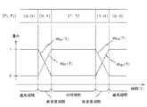
ここで、波形予測部142による波形予測処理に関連する期間について、図4を参照して説明する。なお、再生用チャンネルの放送音声に関する音声信号DADが欠落する上述した欠落期間は、時刻T-1から時刻T1(>T-1)までの期間であるものとする。ここで、欠落期間である旨は、上述したように、欠落期間指示DPIが「H」レベルとなることにより示される。
ここで、波形予測部142による波形予測処理に関連する期間について、図4を参照して説明する。なお、再生用チャンネルの放送音声に関する音声信号DADが欠落する上述した欠落期間は、時刻T-1から時刻T1(>T-1)までの期間であるものとする。ここで、欠落期間である旨は、上述したように、欠落期間指示DPIが「H」レベルとなることにより示される。
波形予測部142は、欠落期間よりも前の期間である前音声期間(時刻T-4(<T-1)から時刻T-2(T-4<T-2≦T-1)までの期間)の音声信号DADに関するデータに基づいて、当該前音声期間における音声信号DADに対応する波形情報(以下、「前音声波形情報」という)を算出する。また、波形予測部142は、欠落期間よりも後の期間である後音声期間(時刻T2(≧T1)から時刻T4(>T2)までの期間)の音声信号DADに関するデータに基づいて、当該後音声期間における音声信号DADに対応する波形情報(以下、「後音声波形情報」という)を算出する。
なお、前音声期間の期間長(=T-2-T-4)は、後述する前音声波形情報の算出処理により、所望の精度で前音声波形情報を迅速に得るとの観点から、実験、シミュレーション、経験等に基づいて、予め定められる。また、後音声期間の期間長(=T4-T2)は、後述する後音声波形情報の算出処理により、所望の精度で後音声波形情報を迅速に得るとの観点から、実験、シミュレーション、経験等に基づいて、予め定められる。
本実施形態では、時刻T-2は時刻T-1よりも前の時刻であり、時刻T2は時刻T1よりも後の時刻となっている。これは、欠落期間の直前及び直後においは、音声信号DADが放送音声を確実に反映できていない可能性があることを考慮したためである。
かかる前音声期間の期間長及び後音声期間の期間長の情報、欠落期間と前音声期間との時間間隔、及び、欠落期間と後音声期間との時間間隔は、波形予測部142内に保持されている。本実施形態では、前音声期間の期間長と、後音声期間の期間長とは同一長となっている。また、本実施形態では、欠落期間と前音声期間との時間間隔、及び、欠落期間と後音声期間との時間間隔は、同一となっている。
なお、以下の説明においては、波形予測期間における前音声期間と後音声期間との間の期間(時刻T-2から時刻T2までの期間)を中間期間と呼ぶものとする。
上述の前音声波形情報及び後音声波形情報に基づいて、波形予測部142は、波形予測期間における予測波形を算出する。かかる波形予測期間は、時刻T-3(T-4<T-3<T-2)から、時刻T3(T2<T3<T4)までの期間となっている。このため、波形予測期間には、上述した欠落期間に加えて、時刻T-3から時刻T-2までの前重複期間(第1重複期間)、及び、時刻T2から時刻T3までの後重複期間(第2重複期間)が含まれるようになっている。
なお、前重複期間の期間長(=T-2-T-3)及び後重複期間の期間長(=T3-T2)は、後述する出力音声信号生成部143が行う出力音声信号の生成処理により生成される出力音声信号AODに対応する音声波形の不連続性の発生を防止するとの観点から、実験、シミュレーション、経験等に基づいて、予め定められる。
かかる前重複期間の期間長及び後重複期間の期間長の情報は、波形予測部142内に保持されている。本実施形態では、前重複期間の期間長と、後重複期間の期間長とは同一となっている。
なお、本実施形態では、上述した欠落期間指示DPIの信号レベルの変化タイミング、及び、ストローブ指示STBの受信状況、並びに、上述したように波形予測部142の内部に保持されている内部に保持されているバッファ記憶部141の内部記憶部の記憶容量、前音声期間の期間長及び後音声期間の期間長の情報、欠落期間と前音声期間との時間間隔、欠落期間と後音声期間との時間間隔、前重複期間の期間長及び後重複期間の期間長に基づいて、波形予測部142は、バッファ記憶部141から出力されるデータが、前重複期間、後重複期間、及び、前重複期間と後重複期間との間の期間に対応するデータであるかを判断ことができるようになっている。
《予測波形情報PWIのビット構成》
次に、予測波形情報PWIのビット構成について説明する。本実施形態では、図5に示されるように、予測波形情報PWIでは、上位2ビットにより、各時刻におけるフラグFLG[F1,F0]の値が表され、他のビットにより、各時刻における予測波形データPWD[DN-1,DN-2,…,D1,D0]の値が表されるようになっている。
次に、予測波形情報PWIのビット構成について説明する。本実施形態では、図5に示されるように、予測波形情報PWIでは、上位2ビットにより、各時刻におけるフラグFLG[F1,F0]の値が表され、他のビットにより、各時刻における予測波形データPWD[DN-1,DN-2,…,D1,D0]の値が表されるようになっている。
ここで、本実施形態では、値[F1,F0]が値[0,0]の場合には、予測波形データPWDが、波形予測期間以外の通常期間のデータであることが示され、値[F1,F0]が値[0,1]の場合には、予測波形データPWDが、前重複期間のデータであることが示される。また、値[F1,F0]が値[1,0]の場合には、予測波形データPWDが、後重複期間のデータであることが示され、値[F1,F0]が値[1,1]の場合には、予測波形データPWDが、中間期間のデータであることが示される。
《重み付け平均で採用している重み》
次いで、出力音声信号生成部143が、重み付け平均の算出において採用する重みについて説明する。
次いで、出力音声信号生成部143が、重み付け平均の算出において採用する重みについて説明する。
出力音声信号生成部143は、前重複期間においては、データMODの値(=N(T))の重みをWNF(T)とし、予測波形データPWDの値(=P(T))の重みをWPF(T)として、値N(T)と値P(T)との重み付け平均(=Z(T))を、次の(1)式により算出する。
Z(T)=WNF(T)・N(T)+WPF(T)・P(T) …(1)
Z(T)=WNF(T)・N(T)+WPF(T)・P(T) …(1)
ここで、本実施形態では、図6に示されるように、重みWNF(T)は、前重複期間において、「1」から「0」へ直線的に減少するようになっている。また、重みWPF(T)は、前重複期間において、「0」から「1」へ直線的に増加するようになっている。
出力音声信号生成部143は、後重複期間においては、データMODの値の重みをWNR(T)とし、予測波形データPWDの値の重みをWPR(T)として、値N(T)と値P(T)との重み付け平均(=Z(T))を、次の(2)式により算出する。
Z(T)=WNR(T)・N(T)+WPR(T)・P(T) …(2)
Z(T)=WNR(T)・N(T)+WPR(T)・P(T) …(2)
ここで、本実施形態では、図6に示されるように、重みWNR(T)は、後重複期間において、「0」から「1」へ直線的に増加するようになっている。また、重みWPR(T)は、後重複期間において、「1」から「0」へ直線的に減少するようになっている。
[動作]
次に、上記のように構成された放送受信装置100の動作について、音声信号補正装置140による音声信号補正処理に主に着目して説明する。
次に、上記のように構成された放送受信装置100の動作について、音声信号補正装置140による音声信号補正処理に主に着目して説明する。
なお、放送受信装置100は、放送受信動作を開始しており、制御ユニット190は、既に、動作開始を指定した動作制御指令RSTを音声信号補正装置140へ送っているものとする。また、制御ユニット190は、操作入力ユニット160に入力された選局指定に従って、再生チャンネルの設定をRF処理ユニット120に対して行っているものとする。さらに、操作入力ユニット160に入力された出力音量指定に従って、出力音量の設定を音出力ユニット150に対して行っているものとする。
すなわち、放送受信装置100では、最適局サーチ処理の期間を除いて、当該再生チャンネルを利用した放送に対応する音声信号DAD及びストローブ指示STBが、音声信号補正装置140に供給されているものとする。また、放送受信装置100では、当該再生チャンネルを利用した放送に対応する出力音声信号AODが、音出力ユニット150に供給されているものとする。
こうした動作状態に放送受信装置100がある場合において、最適局サーチ処理が定期的に実行される。かかる最適局サーチ処理の開始に際しては、制御ユニット190が、欠落期間指示DPIのレベルを「L」から「H」に変化させる。また、最適局サーチ処理の終了に際しては、制御ユニット190が、欠落期間指示DPIのレベルを「H」から「L」に変化させる。
こうした動作状態に放送受信装置100がある場合に、音声信号補正装置140では、バッファ記憶部141によるデータバッファリング処理、波形予測部142による波形予測処理及び同期出力処理、並びに、出力音声信号生成部143による出力音声生成処理が実行される。
<データバッファリング処理>
次に、バッファ記憶部141によるデータバッファリング処理について説明する。データバッファリング処理に際して、バッファ記憶部141は、ストローブ指示STBにより示される同期タイミングで、音声信号DADとして供給されているデータ値を内部記憶部に順次書き込む。そして、バッファ記憶部141は、内部記憶部内における最老データを、データMODとして出力音声信号生成部143へ送るとともに、最新のデータが書き込まれている内部記憶部におけるバッファポインタBPAを波形予測部142へ送る。
次に、バッファ記憶部141によるデータバッファリング処理について説明する。データバッファリング処理に際して、バッファ記憶部141は、ストローブ指示STBにより示される同期タイミングで、音声信号DADとして供給されているデータ値を内部記憶部に順次書き込む。そして、バッファ記憶部141は、内部記憶部内における最老データを、データMODとして出力音声信号生成部143へ送るとともに、最新のデータが書き込まれている内部記憶部におけるバッファポインタBPAを波形予測部142へ送る。
また、バッファ記憶部141は、出力音声信号生成部143による読み取りが行われていないデータが、内部記憶部内の全ての領域に書き込まれた状態になると、出力音声信号生成部143へバッファフル指示BFLを送る。そして、バッファ記憶部141は、出力音声信号生成部143から送られた読取報告BDRを受けると、その時点における内部記憶部内の最老データを消去する。
<波形予測処理>
次いで、波形予測部142による波形予測処理について説明する。波形予測処理に際しては、図7に示されるように、まず、ステップS11において、波形予測部142が、欠落期間指示DPIが「L」レベルから「H」レベルに変化したか否かを判定することにより、欠落期間が開始したか否かを判定する。この判定の結果が否定的であった場合(ステップS11:N)には、ステップS11の処理が繰り返される。
次いで、波形予測部142による波形予測処理について説明する。波形予測処理に際しては、図7に示されるように、まず、ステップS11において、波形予測部142が、欠落期間指示DPIが「L」レベルから「H」レベルに変化したか否かを判定することにより、欠落期間が開始したか否かを判定する。この判定の結果が否定的であった場合(ステップS11:N)には、ステップS11の処理が繰り返される。
欠落期間指示DPIが「L」レベルから「H」レベルに変化し、ステップS11における判定の結果が肯定的となると(ステップS11:Y)、処理はステップS12へ進む。このステップS12では、波形予測部142が、今回の欠落期間に対する前音声期間における波形情報である前音声波形情報を算出する。
かかる前音声波形情報の算出に際して、波形予測部142は、まず、その時点でバッファ記憶部141から送られているバッファポインタBPAに基づいて、バッファ記憶部141の内部記憶部における前音声期間に対応するデータの領域を特定する。引き続き、波形予測部142は、今回特定された記憶領域におけるデータを読み取る。
次に、波形予測部142は、読み取られたデータに基づいて、前音声期間における音声の時間波形をフーリエ変換して、振幅スペクトル(前振幅スペクトル)及び位相スペクトル(前位相スペクトル)を、前音声波形情報として算出する。そして、波形予測部142は、算出された前音声波形情報を内部に保持し、ステップS12の処理を終了する。
次いで、ステップS13において、波形予測部142が、欠落期間指示DPIが「H」レベルから「L」レベルに変化したか否かを判定することにより、欠落期間が終了したか否かを判定する。この判定の結果が否定的であった場合(ステップS13:N)には、ステップS13の処理が繰り返される。
欠落期間指示DPIが「H」レベルから「L」レベルに変化し、ステップS13における判定の結果が肯定的となると(ステップS13:Y)、処理はステップS14へ進む。このステップS14では、波形予測部142が、後音声期間が終了したか否かを判定する。ここで、波形予測部142は、欠落期間指示DPIが「H」レベルから「L」レベルに変化した後に、再生処理ユニット130から周期的に送られたストローブ指示STBの数が、予め定められた数に達したか否かを判定することにより、後音声期間が終了したか否かを判定する。
ステップS14における判定の結果が否定的であった場合(ステップS14:N)には、ステップS14の処理が繰り返される。そして、後音声期間が終了し、ステップS14における判定の結果が肯定的となると(ステップS14:Y)、処理はステップS15へ進む。
ステップS15では、波形予測部142が、今回の欠落期間に対する後音声期間における波形情報である後音声波形情報を算出する。
かかる後音声波形情報の算出に際して、波形予測部142は、まず、その時点でバッファ記憶部141から送られているバッファポインタBPAに基づいて、バッファ記憶部141の内部記憶部における後音声期間におけるデータの領域を特定する。引き続き、波形予測部142は、今回特定された記憶領域におけるデータを読み取る。
次に、波形予測部142は、読み取られたデータに基づいて、後音声期間における音声の時間波形をフーリエ変換して、振幅スペクトル(後振幅スペクトル)及び位相スペクトル(後位相スペクトル)を、後音声波形情報として算出する。そして、波形予測部142は、算出された後音声波形情報を内部に保持し、ステップS15の処理を終了する。
次いで、ステップS16において、波形予測部142が、平均波形情報を算出する。かかる平均波形情報の算出に際しては、波形予測部142が、前振幅スペクトルと後振幅スペクトルとの平均である平均振幅スペクトルと、前位相スペクトルと後位相スペクトルとの平均である平均位相スペクトルとを、平均波形情報として算出する。
次に、ステップS17において、波形予測部142が、今回算出された平均波形情報に対する逆フーリエ変換を行って、今回の波形予測期間における時間波形である予測波形を算出する。そして、波形予測部142は、算出された予測波形のデータを内部に保持する。
こうして予測波形の算出が終了すると、処理はステップS11へ戻る。以後、ステップS11~S17の処理が繰り返され、欠落期間が発生するたびに、波形予測期間における予測波形が算出される。
<同期出力処理>
次に、波形予測部142による同期出力処理について説明する。この同期出力処理は、上記の波形予測処理と並行して実行される。
次に、波形予測部142による同期出力処理について説明する。この同期出力処理は、上記の波形予測処理と並行して実行される。
かかる同期出力処理に際しては、図8に示されるように、まず、ステップS21において、波形予測部142が、新たなストローブ指示STBを受けたか否かを判定する。この判定の結果が否定的であった場合(ステップS21:N)には、ステップS21の処理が繰り返される。
再生処理ユニット130から送られた新たなストローブ指示STBを受け、ステップS21の判定の結果が肯定的となると(ステップS21:Y)、処理はステップS22へ進む。このステップS22では、波形予測部142が、バッファ記憶部141から出力されているデータMODが、通常期間のデータか否かを判定する。この判定結果が肯定的であった場合(ステップS22:Y)には、処理はステップS23へ進む。
ステップS23では、波形予測部142が、フラグFLG[F1,F0]が値[0,0]であり、予測波形データPWDの値が不定の予測波形情報PWIを、出力音声信号生成部143へ送る。そして、処理はステップS21へ戻る。
上記のステップS22における判定の結果が否定的であった場合(ステップS22:N)には、処理はステップS24へ進む。このステップS24では、波形予測部142が、バッファ記憶部141から出力されているデータMODが、前重複期間のデータか否かを判定する。この判定結果が肯定的であった場合(ステップS24:Y)には、処理はステップS25へ進む。
ステップS25では、波形予測部142が、フラグFLG[F1,F0]が値[0,1]であり、予測波形データPWDの値が、バッファ記憶部141から出力されているデータMODに時間的に対応する予測波形データの値である予測波形情報PWIを、出力音声信号生成部143へ送る。そして、処理はステップS21へ戻る。
上記のステップS24における判定の結果が否定的であった場合(ステップS24:N)には、処理はステップS26へ進む。このステップS26では、波形予測部142が、バッファ記憶部141から出力されているデータMODが、中間期間のデータか否かを判定する。この判定結果が肯定的であった場合(ステップS26:Y)には、処理はステップS27へ進む。
ステップS27では、波形予測部142が、フラグFLG[F1,F0]が値[1,1]であり、予測波形データPWDの値が、バッファ記憶部141から出力されているデータMODに時間的に対応する予測波形データの値である予測波形情報PWIを、出力音声信号生成部143へ送る。そして、処理はステップS21へ戻る。
上記のステップS26における判定の結果が否定的であった場合(ステップS26:N)には、処理はステップS28へ進む。このステップS28では、波形予測部142が、フラグFLG[F1,F0]が値[1,0]であり、予測波形データPWDの値が、バッファ記憶部141から出力されているデータMODに時間的に対応する予測波形データの値である予測波形情報PWIを、出力音声信号生成部143へ送る。そして、処理はステップS21へ戻る。
以後、ステップS21~S28の処理が繰り返される。この結果、ストローブ指示STBを受けるたびに、波形予測部142からは、バッファ記憶部141から出力されているデータMODに時間的に対応する予測波形情報PWIが、出力音声信号生成部143へ送られる。
<出力音声生成処理>
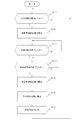
次に、出力音声信号生成部143による出力音声生成処理について説明する。かかる出力音声生成処理に際しては、図9に示されるように、まず、ステップS31において、出力音声信号生成部143が、新たなバッファフル指示BFLを受けたか否かを判定する。この判定の結果が否定的であった場合(ステップS31:N)には、ステップS31の処理が繰り返される。
次に、出力音声信号生成部143による出力音声生成処理について説明する。かかる出力音声生成処理に際しては、図9に示されるように、まず、ステップS31において、出力音声信号生成部143が、新たなバッファフル指示BFLを受けたか否かを判定する。この判定の結果が否定的であった場合(ステップS31:N)には、ステップS31の処理が繰り返される。
バッファ記憶部141から送られた新たなバッファフル指示BFLを受け、ステップS31における判定の結果が肯定的となると(ステップS31:Y)、処理はステップS32へ進む。このステップS32では、出力音声信号生成部143が、バッファ記憶部141から送られているデータMOD、及び、波形予測部142から送られている予測波形情報PWIを読み取る。
引き続き、出力音声信号生成部143は、読取報告BDRをバッファ記憶部141へ送る。この結果、バッファ記憶部141では、内部記憶部内の最老データが消去され、バッファ記憶部141におけるバッファフル状態が解除される。
次に、ステップS33において、出力音声信号生成部143が、読み取られた予測波形情報PWIにおけるフラグFLG[F1,F0]の値が[0,0]であるか否かを判定することにより、通常期間におけるデータが読み取られたか否かを判定する。この判定の結果が肯定的であった場合(ステップS33:Y)には、処理はステップS34へ進む。
ステップS34では、出力音声信号生成部143が、読み取られたデータMOD及び予測波形情報PWIにおける予測波形データPWDのうち、データMODを出力音声データとし、出力音声信号AODとして、音出力ユニット150へ送る。そして、処理はステップS31へ戻る。
上記のステップS33における判定の結果が否定的であった場合(ステップS33:N)には、処理はステップS35へ進む。このステップS35では、出力音声信号生成部143が、読み取られたフラグFLG[F1,F0]の値が[0,1]であるか否かを判定することにより、前重複期間におけるデータが読み取られたか否かを判定する。この判定の結果が肯定的であった場合(ステップS35:Y)には、処理はステップS36へ進む。
ステップS36では、出力音声信号生成部143が、読み取られたデータMOD及び予測波形データPWD、並びに、読み取られたフラグFLG[F1,F0]の値が[0,1]となった後における読取報告BDRの発行数から特定される前重複期間の開始からの経過時間に基づき、上述した(1)式により、出力音声データの値(Z(T))を算出する。そして、算出された出力音声データの値を、出力音声信号AODとして、音出力ユニット150へ送る。この後、処理はステップS31へ戻る。
上記のステップS35における判定の結果が否定的であった場合(ステップS35:N)には、処理はステップS37へ進む。このステップS37では、出力音声信号生成部143が、読み取られたフラグFLG[F1,F0]の値が[1,1]であるか否かを判定することにより、中間期間におけるデータが読み取られたか否かを判定する。この判定の結果が肯定的であった場合(ステップS37:Y)には、処理はステップS38へ進む。
ステップS38では、出力音声信号生成部143が、読み取られたデータMOD及び予測波形データPWDのうち、予測波形データPWDを出力音声データとし、出力音声信号AODとして、音出力ユニット150へ送る。そして、処理はステップS31へ戻る。
上記のステップS37における判定の結果が否定的であった場合(ステップS37:N)には、処理はステップS39へ進む。このステップS39では、出力音声信号生成部143が、読み取られたデータMOD及び予測波形データPWD、並びに、読み取られたフラグFLG[F1,F0]の値が[1,0]となった後における読取報告BDRの発行数から特定される後重複期間の開始からの経過時間に基づき、上述した(2)式により、出力音声データの値(Z(T))を算出する。そして、算出された出力音声データの値を、出力音声信号AODとして、音出力ユニット150へ送る。この後、処理はステップS31へ戻る。
以後、ステップS31~S39の処理が繰り返される。この結果、バッファフル指示BFLを受けるたびに、出力音声信号生成部143からは、新たなデータ値が出力音声信号AODとして、音出力ユニット150へ送られる。そして、音声信号補正装置140により補正された出力音声信号AODに従った音声が、音出力ユニット150のスピーカから出力される。
以上説明したように、本実施形態では、再生用チャンネルの放送音声に関する音声信号DADが欠落している欠落期間よりも前の期間である前音声期間における音声波形である前音声波形、及び、当該欠落期間よりも後の期間である後音声期間における音声波形である後音声波形に基づいて、波形予測部142が、波形予測期間における予測波形を算出する。ここで、波形予測期間は、欠落期間と、前音声期間に重なる前重複期間と、後音声期間に重なる後重複期間とを含む連続的な期間となっている。
そして、出力音声信号生成部143が、前音声波形、後音声波形及び予測波形に基づいて、波形予測期間における出力音声信号AODを生成する。ここで、波形予測期間における出力音声信号AODが、前重複期間及び後重複期間においては音声信号DADの波形と予測波形とを重み付け平均した波形を有し、前重複期間と後重複期間との間の中間期間においては予測波形を有する信号となるように、出力音声信号生成部143が、出力音声信号AODを生成する。
したがって、本実施形態の音声信号補正装置によれば、聴取者にとっての不連続感を抑制することができる出力音声信号を生成することができる。
また、本実施形態では、前重複期間及び後重複期間における音声信号DADの波形と予測波形との重み付け平均では、欠落期間に近いほど、予測波形の重みが大きくなっている。このため、出力音声信号AODに対応する音声波形の不連続性の発生を効果的に抑制することができる。
また、本実施形態では、予測波形の算出に際して、波形予測部142が、まず、前音声波形をフーリエ変換して、前振幅スペクトル及び前位相スペクトルを算出するとともに、後音声波形をフーリエ変換して、後振幅スペクトル及び後位相スペクトルを算出する。引き続き、波形予測部142が、前振幅スペクトルと後振幅スペクトルとの平均振幅スペクトル、及び、前位相スペクトルと後位相スペクトルとの平均位相スペクトルを算出する。そして、波形予測部142が、平均振幅スペクトル及び平均位相スペクトルを逆フーリエ変換して、予測波形をデジタル演算により算出する。このため、簡易な構成で、予測波形を合理的に算出することができる。
[実施形態の変形]
本発明は、上記の実施形態に限定されるものではなく、様々な変形が可能である。
本発明は、上記の実施形態に限定されるものではなく、様々な変形が可能である。
例えば、上記の実施形態では、欠落期間と前音声期間との間、及び、欠落期間と後音声期間との間に間隔を設けることにしたが、欠落期間の直前に前音声期間を設定してもよいし、欠落期間の直後に後音声期間を設定してもよい。
また、上記の実施形態では、前重複期間及び後重複期間における出力音声信号の生成に際して、上述した図6に示すように、直線的に変化する重みを採用して重み付け平均を算出するようにしたが、曲線的に変化する重みを採用して重み付け平均を算出するようにしてもよい。
また、上記の実施形態では、バッファ記憶部からの時間順次のデータ出力後に波形予測期間における音声信号の補正を行うようにした。これに対し、バッファ記憶部からの時間順次のデータ出力が波形予測期間に対応するデータ出力となる前に、上記の実施形態における出力音声信号生成部による音声信号の補正演算と同様の演算を行って、パッファ記憶部内の波形予測期間に対応するデータを補正処理結果のデータに書き換えるようにしてもよい。
また、上記の実施形態では、最適局サーチ期間における再生用チャンネルの放送音声に関する音声信号の欠落が発生する場合に、本発明の音声信号補正装置が音声信号の補正を行うようにした。これに対し、受信可能な放送局を自動検索する際における再生用チャンネルの放送音声に関する音声信号の欠落が発生する場合にも、本発明の音声信号補正装置が音声信号の補正を行うようにしてもよい。
また、上記の実施形態では、RDS方式を採用する放送受信装置が本発明の音声信号補正装置を備えるようにしたが、音声信号が欠落期間を有する場合には、RDS方式を採用する放送受信装置以外の装置が、本発明の音声信号補正装置を備えるようにすることができるのは、勿論である。
なお、上記の実施形態における音声信号補正装置をDSP(Digital Signal Processor)等を備えた演算手段としてのコンピュータとして構成し、予め用意されたプログラムを当該コンピュータで実行することにより、上記の実施形態における処理の一部又は全部を実行するようにしてもよい。このプログラムはハードディスク、CD-ROM、DVD等のコンピュータで読み取り可能な記録媒体に記録され、当該コンピュータによって記録媒体から読み出されて実行される。また、このプログラムは、CD-ROM、DVD等の可搬型記録媒体に記録された形態で取得されるようにしてもよいし、インターネットなどのネットワークを介した配信の形態で取得されるようにしてもよい。
Claims (7)
- 欠落期間を含む入力音声信号を補正して連続的な出力音声信号を生成する音声信号補正装置であって、
前記欠落期間よりも長い所定時間にわたって、現時点までの前記入力音声信号の波形を記憶するバッファ記憶部と;
前記バッファ記憶部内における前記欠落期間よりも前の期間である第1期間の第1波形、及び、前記欠落期間よりも後の期間である第2期間の第2波形に基づいて、波形予測期間における予測波形を算出する波形予測部と;
前記第1波形、前記第2波形及び前記算出された予測波形に基づいて、前記波形予測期間における前記出力音声信号を生成する出力音声信号生成部と;を備え、
前記波形予測期間は、前記欠落期間と、前記第1期間に重なる第1重複期間と、前記第2期間に重なる第2重複期間とを含む連続的な期間であり、
前記波形予測期間における前記出力音声信号は、前記第1及び第2重複期間においては前記入力音声信号の波形と前記予測波形とを重み付け平均した波形を有し、前記第1及び第2重複期間以外の期間においては前記予測波形を有する信号である、
ことを特徴とする音声信号補正装置。 - 前記第1及び第2重複期間における前記入力音声信号の波形と前記予測波形との重み付け平均では、前記欠落期間に近いほど、前記予測波形の重みが大きくなっている、ことを特徴とする請求項1に記載の音声信号補正装置。
- 前記波形予測部は、
前記第1波形に対するフーリエ変換を行って、第1振幅スペクトル及び第1位相スペクトルを算出し、
前記第2波形に対するフーリエ変換を行って、第2振幅スペクトル及び第2位相スペクトルを算出し、
前記第1振幅スペクトルと前記第2振幅スペクトルとの平均的な振幅スペクトルである第3振幅スペクトル、及び、前記第1位相スペクトルと前記第2位相スペクトルとの平均的な位相スペクトルである第3位相スペクトルを算出し、
前記第3振幅スペクトル及び前記第3位相スペクトルを逆フーリエ変換して、前記予測波形を算出する、
ことを特徴とする請求項1又は2に記載の音声信号補正装置。 - 前記入力音声信号は、放送波に含まれる音声成分が復調された信号である、ことを特徴とする請求項1~3のいずれか一項に記載の音声信号補正装置。
- 入力音声信号の欠落期間よりも長い所定時間にわたって、現時点までの前記入力音声信号の波形を記憶するバッファ記憶部を備え、前記入力音声信号を補正して連続的な出力音声信号を生成する音声信号補正装置で使用される音声信号補正方法あって、
前記バッファ記憶部内における前記欠落期間よりも前の期間である第1期間の第1波形、及び、前記欠落期間よりも後の期間である第2期間の第2波形に基づいて、波形予測期間における予測波形を算出する波形予測工程と;
前記第1波形、前記第2波形及び前記算出された予測波形に基づいて、前記波形予測期間における前記出力音声信号を生成する出力音声信号生成工程と;を備え、
前記波形予測期間は、前記欠落期間と、前記第1期間に重なる第1重複期間と、前記第2期間に重なる第2重複期間とを含む連続的な期間であり、
前記波形予測期間における前記出力音声信号は、前記第1及び第2重複期間においては前記入力音声信号の波形と前記予測波形とを重み付け平均した波形を有し、前記第1及び第2重複期間以外の期間においては前記予測波形を有する信号である、
ことを特徴とする音声信号補正方法。 - 請求項5に記載の音声信号補正方法を演算部に実行させる、ことを特徴とする音声信号補正プログラム。
- 請求項6に記載の音声信号補正プログラムが、演算部により読み取り可能に記録されている、ことを特徴とする記録媒体。
Priority Applications (3)
| Application Number | Priority Date | Filing Date | Title |
|---|---|---|---|
| JP2013545679A JP5671630B2 (ja) | 2011-11-22 | 2011-11-22 | 音声信号補正装置及び音声信号補正方法 |
| EP11876150.1A EP2784777A4 (en) | 2011-11-22 | 2011-11-22 | AUDIO SIGNAL CORRECTION DEVICE AND AUDIO SIGNAL CORRECTION METHOD |
| PCT/JP2011/076854 WO2013076801A1 (ja) | 2011-11-22 | 2011-11-22 | 音声信号補正装置及び音声信号補正方法 |
Applications Claiming Priority (1)
| Application Number | Priority Date | Filing Date | Title |
|---|---|---|---|
| PCT/JP2011/076854 WO2013076801A1 (ja) | 2011-11-22 | 2011-11-22 | 音声信号補正装置及び音声信号補正方法 |
Publications (1)
| Publication Number | Publication Date |
|---|---|
| WO2013076801A1 true WO2013076801A1 (ja) | 2013-05-30 |
Family
ID=48469282
Family Applications (1)
| Application Number | Title | Priority Date | Filing Date |
|---|---|---|---|
| PCT/JP2011/076854 Ceased WO2013076801A1 (ja) | 2011-11-22 | 2011-11-22 | 音声信号補正装置及び音声信号補正方法 |
Country Status (3)
| Country | Link |
|---|---|
| EP (1) | EP2784777A4 (ja) |
| JP (1) | JP5671630B2 (ja) |
| WO (1) | WO2013076801A1 (ja) |
Cited By (2)
| Publication number | Priority date | Publication date | Assignee | Title |
|---|---|---|---|---|
| WO2016117110A1 (ja) * | 2015-01-23 | 2016-07-28 | パイオニア株式会社 | 受信装置及び受信信号処理方法 |
| JP7201033B2 (ja) | 2017-03-24 | 2023-01-10 | ヤマハ株式会社 | 音データ処理装置、音データ処理方法及びプログラム |
Citations (4)
| Publication number | Priority date | Publication date | Assignee | Title |
|---|---|---|---|---|
| JPH0223744A (ja) * | 1988-07-13 | 1990-01-25 | Oki Electric Ind Co Ltd | 音声パケット補間方法 |
| JP2005143013A (ja) * | 2003-11-10 | 2005-06-02 | Oki Electric Ind Co Ltd | 復号装置 |
| JP2005269547A (ja) | 2004-03-22 | 2005-09-29 | Fujitsu Ten Ltd | 受信機及び音響機器 |
| WO2008111158A1 (ja) * | 2007-03-12 | 2008-09-18 | Fujitsu Limited | 音声波形補間装置および方法 |
Family Cites Families (6)
| Publication number | Priority date | Publication date | Assignee | Title |
|---|---|---|---|---|
| JP4249821B2 (ja) * | 1998-08-31 | 2009-04-08 | 富士通株式会社 | ディジタルオーディオ再生装置 |
| DE60029715T2 (de) * | 1999-04-19 | 2007-08-02 | At & T Corp. | Verfahren und anordnung zur verschleierung von rahmenausfall |
| US7047190B1 (en) * | 1999-04-19 | 2006-05-16 | At&Tcorp. | Method and apparatus for performing packet loss or frame erasure concealment |
| JP2004023191A (ja) * | 2002-06-12 | 2004-01-22 | Nippon Telegr & Teleph Corp <Ntt> | 信号符号化方法及び信号復号化方法及び信号符号化装置及び信号復号化装置及び信号符号化プログラム及び信号復号化プログラム |
| JP2006171353A (ja) * | 2004-12-15 | 2006-06-29 | Nec Engineering Ltd | 音声復号システム |
| US8255207B2 (en) * | 2005-12-28 | 2012-08-28 | Voiceage Corporation | Method and device for efficient frame erasure concealment in speech codecs |
-
2011
- 2011-11-22 EP EP11876150.1A patent/EP2784777A4/en not_active Withdrawn
- 2011-11-22 WO PCT/JP2011/076854 patent/WO2013076801A1/ja not_active Ceased
- 2011-11-22 JP JP2013545679A patent/JP5671630B2/ja not_active Expired - Fee Related
Patent Citations (4)
| Publication number | Priority date | Publication date | Assignee | Title |
|---|---|---|---|---|
| JPH0223744A (ja) * | 1988-07-13 | 1990-01-25 | Oki Electric Ind Co Ltd | 音声パケット補間方法 |
| JP2005143013A (ja) * | 2003-11-10 | 2005-06-02 | Oki Electric Ind Co Ltd | 復号装置 |
| JP2005269547A (ja) | 2004-03-22 | 2005-09-29 | Fujitsu Ten Ltd | 受信機及び音響機器 |
| WO2008111158A1 (ja) * | 2007-03-12 | 2008-09-18 | Fujitsu Limited | 音声波形補間装置および方法 |
Non-Patent Citations (1)
| Title |
|---|
| See also references of EP2784777A4 * |
Cited By (2)
| Publication number | Priority date | Publication date | Assignee | Title |
|---|---|---|---|---|
| WO2016117110A1 (ja) * | 2015-01-23 | 2016-07-28 | パイオニア株式会社 | 受信装置及び受信信号処理方法 |
| JP7201033B2 (ja) | 2017-03-24 | 2023-01-10 | ヤマハ株式会社 | 音データ処理装置、音データ処理方法及びプログラム |
Also Published As
| Publication number | Publication date |
|---|---|
| JPWO2013076801A1 (ja) | 2015-04-27 |
| EP2784777A4 (en) | 2015-07-01 |
| EP2784777A1 (en) | 2014-10-01 |
| JP5671630B2 (ja) | 2015-02-18 |
Similar Documents
| Publication | Publication Date | Title |
|---|---|---|
| JP5671630B2 (ja) | 音声信号補正装置及び音声信号補正方法 | |
| JP5033924B2 (ja) | 受信装置、受信処理方法、受信処理プログラム及び記録媒体 | |
| JP2011014994A (ja) | ラジオ放送受信装置、ラジオ放送受信方法、およびラジオ放送受信プログラム | |
| JP2014072678A (ja) | 受信装置、及び、受信制御方法 | |
| JP2012209710A (ja) | 放送受信装置、制御方法、及び制御プログラム | |
| JP5653793B2 (ja) | ラジオ放送受信機 | |
| JP2011151443A (ja) | デジタル放送受信装置及びデジタル放送受信方法 | |
| US8103230B2 (en) | Broadcasting receiver, broadcasting identification method, broadcasting identification program, and recording medium therefor | |
| JP2010252072A (ja) | 移動型デジタル放送受信装置及び移動型デジタル放送受信装置におけるチャンネルサーチ方法 | |
| US8229583B2 (en) | Apparatus and method of setting received broadcasting sound source data as functional sound of mobile phone | |
| JP2013131927A (ja) | 放送受信装置及び放送受信方法 | |
| JP4401837B2 (ja) | 放送受信機及び受信切り替え方法 | |
| JP2009225144A (ja) | 受信装置、受信制御方法、受信制御プログラム及びその記録媒体 | |
| JP6257894B2 (ja) | 放送受信装置及び放送受信方法 | |
| JP5746989B2 (ja) | ノイズ検出装置、ノイズ低減装置及びノイズ検出方法 | |
| JP2009049954A (ja) | 受信装置および受信方法 | |
| JP3135763B2 (ja) | 多重放送受信機 | |
| JP4312652B2 (ja) | ラジオ受信機 | |
| JP2010245694A (ja) | 受信装置、受信処理方法、受信処理プログラム及びその記録媒体 | |
| JP2009224931A (ja) | 受信装置、受信制御方法、受信制御プログラム及び記録媒体 | |
| JP2014204274A (ja) | 放送受信装置及び放送受信方法 | |
| JP4851987B2 (ja) | 放送受信装置、選局方法、選局プログラム及びその記録媒体 | |
| JP6144909B2 (ja) | 放送受信装置及び放送受信方法 | |
| JP2018042287A (ja) | 放送受信装置及び放送受信方法 | |
| JP6044984B2 (ja) | ラジオ受信装置 |
Legal Events
| Date | Code | Title | Description |
|---|---|---|---|
| 121 | Ep: the epo has been informed by wipo that ep was designated in this application |
Ref document number: 11876150 Country of ref document: EP Kind code of ref document: A1 |
|
| ENP | Entry into the national phase |
Ref document number: 2013545679 Country of ref document: JP Kind code of ref document: A |
|
| WWE | Wipo information: entry into national phase |
Ref document number: 2011876150 Country of ref document: EP |
|
| NENP | Non-entry into the national phase |
Ref country code: DE |