WO2013076811A1 - 内燃機関の制御システム - Google Patents
内燃機関の制御システム Download PDFInfo
- Publication number
- WO2013076811A1 WO2013076811A1 PCT/JP2011/076918 JP2011076918W WO2013076811A1 WO 2013076811 A1 WO2013076811 A1 WO 2013076811A1 JP 2011076918 W JP2011076918 W JP 2011076918W WO 2013076811 A1 WO2013076811 A1 WO 2013076811A1
- Authority
- WO
- WIPO (PCT)
- Prior art keywords
- air
- fuel ratio
- value
- cng
- fuel
- Prior art date
- Legal status (The legal status is an assumption and is not a legal conclusion. Google has not performed a legal analysis and makes no representation as to the accuracy of the status listed.)
- Ceased
Links
Images




Classifications
-
- F—MECHANICAL ENGINEERING; LIGHTING; HEATING; WEAPONS; BLASTING
- F02—COMBUSTION ENGINES; HOT-GAS OR COMBUSTION-PRODUCT ENGINE PLANTS
- F02D—CONTROLLING COMBUSTION ENGINES
- F02D41/00—Electrical control of supply of combustible mixture or its constituents
- F02D41/30—Controlling fuel injection
-
- F—MECHANICAL ENGINEERING; LIGHTING; HEATING; WEAPONS; BLASTING
- F02—COMBUSTION ENGINES; HOT-GAS OR COMBUSTION-PRODUCT ENGINE PLANTS
- F02D—CONTROLLING COMBUSTION ENGINES
- F02D19/00—Controlling engines characterised by their use of non-liquid fuels, pluralities of fuels, or non-fuel substances added to the combustible mixtures
- F02D19/02—Controlling engines characterised by their use of non-liquid fuels, pluralities of fuels, or non-fuel substances added to the combustible mixtures peculiar to engines working with gaseous fuels
- F02D19/021—Control of components of the fuel supply system
- F02D19/023—Control of components of the fuel supply system to adjust the fuel mass or volume flow
- F02D19/024—Control of components of the fuel supply system to adjust the fuel mass or volume flow by controlling fuel injectors
-
- F—MECHANICAL ENGINEERING; LIGHTING; HEATING; WEAPONS; BLASTING
- F02—COMBUSTION ENGINES; HOT-GAS OR COMBUSTION-PRODUCT ENGINE PLANTS
- F02D—CONTROLLING COMBUSTION ENGINES
- F02D41/00—Electrical control of supply of combustible mixture or its constituents
- F02D41/0025—Controlling engines characterised by use of non-liquid fuels, pluralities of fuels, or non-fuel substances added to the combustible mixtures
- F02D41/0027—Controlling engines characterised by use of non-liquid fuels, pluralities of fuels, or non-fuel substances added to the combustible mixtures the fuel being gaseous
-
- F—MECHANICAL ENGINEERING; LIGHTING; HEATING; WEAPONS; BLASTING
- F02—COMBUSTION ENGINES; HOT-GAS OR COMBUSTION-PRODUCT ENGINE PLANTS
- F02D—CONTROLLING COMBUSTION ENGINES
- F02D41/00—Electrical control of supply of combustible mixture or its constituents
- F02D41/02—Circuit arrangements for generating control signals
- F02D41/14—Introducing closed-loop corrections
- F02D41/1438—Introducing closed-loop corrections using means for determining characteristics of the combustion gases; Sensors therefor
- F02D41/1444—Introducing closed-loop corrections using means for determining characteristics of the combustion gases; Sensors therefor characterised by the characteristics of the combustion gases
- F02D41/1454—Introducing closed-loop corrections using means for determining characteristics of the combustion gases; Sensors therefor characterised by the characteristics of the combustion gases the characteristics being an oxygen content or concentration or the air-fuel ratio
- F02D41/1456—Introducing closed-loop corrections using means for determining characteristics of the combustion gases; Sensors therefor characterised by the characteristics of the combustion gases the characteristics being an oxygen content or concentration or the air-fuel ratio with sensor output signal being linear or quasi-linear with the concentration of oxygen
-
- F—MECHANICAL ENGINEERING; LIGHTING; HEATING; WEAPONS; BLASTING
- F02—COMBUSTION ENGINES; HOT-GAS OR COMBUSTION-PRODUCT ENGINE PLANTS
- F02D—CONTROLLING COMBUSTION ENGINES
- F02D41/00—Electrical control of supply of combustible mixture or its constituents
- F02D41/24—Electrical control of supply of combustible mixture or its constituents characterised by the use of digital means
- F02D41/2406—Electrical control of supply of combustible mixture or its constituents characterised by the use of digital means using essentially read only memories
- F02D41/2425—Particular ways of programming the data
- F02D41/2429—Methods of calibrating or learning
- F02D41/2451—Methods of calibrating or learning characterised by what is learned or calibrated
- F02D41/2454—Learning of the air-fuel ratio control
-
- F—MECHANICAL ENGINEERING; LIGHTING; HEATING; WEAPONS; BLASTING
- F02—COMBUSTION ENGINES; HOT-GAS OR COMBUSTION-PRODUCT ENGINE PLANTS
- F02D—CONTROLLING COMBUSTION ENGINES
- F02D13/00—Controlling the engine output power by varying inlet or exhaust valve operating characteristics, e.g. timing
- F02D13/02—Controlling the engine output power by varying inlet or exhaust valve operating characteristics, e.g. timing during engine operation
- F02D13/0203—Variable control of intake and exhaust valves
- F02D13/0215—Variable control of intake and exhaust valves changing the valve timing only
-
- F—MECHANICAL ENGINEERING; LIGHTING; HEATING; WEAPONS; BLASTING
- F02—COMBUSTION ENGINES; HOT-GAS OR COMBUSTION-PRODUCT ENGINE PLANTS
- F02D—CONTROLLING COMBUSTION ENGINES
- F02D19/00—Controlling engines characterised by their use of non-liquid fuels, pluralities of fuels, or non-fuel substances added to the combustible mixtures
- F02D19/02—Controlling engines characterised by their use of non-liquid fuels, pluralities of fuels, or non-fuel substances added to the combustible mixtures peculiar to engines working with gaseous fuels
- F02D19/026—Measuring or estimating parameters related to the fuel supply system
- F02D19/027—Determining the fuel pressure, temperature or volume flow, the fuel tank fill level or a valve position
-
- F—MECHANICAL ENGINEERING; LIGHTING; HEATING; WEAPONS; BLASTING
- F02—COMBUSTION ENGINES; HOT-GAS OR COMBUSTION-PRODUCT ENGINE PLANTS
- F02D—CONTROLLING COMBUSTION ENGINES
- F02D2200/00—Input parameters for engine control
- F02D2200/02—Input parameters for engine control the parameters being related to the engine
- F02D2200/06—Fuel or fuel supply system parameters
- F02D2200/0611—Fuel type, fuel composition or fuel quality
- F02D2200/0612—Fuel type, fuel composition or fuel quality determined by estimation
-
- F—MECHANICAL ENGINEERING; LIGHTING; HEATING; WEAPONS; BLASTING
- F02—COMBUSTION ENGINES; HOT-GAS OR COMBUSTION-PRODUCT ENGINE PLANTS
- F02M—SUPPLYING COMBUSTION ENGINES IN GENERAL WITH COMBUSTIBLE MIXTURES OR CONSTITUENTS THEREOF
- F02M21/00—Apparatus for supplying engines with non-liquid fuels, e.g. gaseous fuels stored in liquid form
- F02M21/02—Apparatus for supplying engines with non-liquid fuels, e.g. gaseous fuels stored in liquid form for gaseous fuels
- F02M21/0203—Apparatus for supplying engines with non-liquid fuels, e.g. gaseous fuels stored in liquid form for gaseous fuels characterised by the type of gaseous fuel
- F02M21/0215—Mixtures of gaseous fuels; Natural gas; Biogas; Mine gas; Landfill gas
-
- F—MECHANICAL ENGINEERING; LIGHTING; HEATING; WEAPONS; BLASTING
- F02—COMBUSTION ENGINES; HOT-GAS OR COMBUSTION-PRODUCT ENGINE PLANTS
- F02M—SUPPLYING COMBUSTION ENGINES IN GENERAL WITH COMBUSTIBLE MIXTURES OR CONSTITUENTS THEREOF
- F02M21/00—Apparatus for supplying engines with non-liquid fuels, e.g. gaseous fuels stored in liquid form
- F02M21/02—Apparatus for supplying engines with non-liquid fuels, e.g. gaseous fuels stored in liquid form for gaseous fuels
- F02M21/0218—Details on the gaseous fuel supply system, e.g. tanks, valves, pipes, pumps, rails, injectors or mixers
- F02M21/0221—Fuel storage reservoirs, e.g. cryogenic tanks
-
- F—MECHANICAL ENGINEERING; LIGHTING; HEATING; WEAPONS; BLASTING
- F02—COMBUSTION ENGINES; HOT-GAS OR COMBUSTION-PRODUCT ENGINE PLANTS
- F02M—SUPPLYING COMBUSTION ENGINES IN GENERAL WITH COMBUSTIBLE MIXTURES OR CONSTITUENTS THEREOF
- F02M26/00—Engine-pertinent apparatus for adding exhaust gases to combustion-air, main fuel or fuel-air mixture, e.g. by exhaust gas recirculation [EGR] systems
- F02M26/01—Internal exhaust gas recirculation, i.e. wherein the residual exhaust gases are trapped in the cylinder or pushed back from the intake or the exhaust manifold into the combustion chamber without the use of additional passages
-
- Y—GENERAL TAGGING OF NEW TECHNOLOGICAL DEVELOPMENTS; GENERAL TAGGING OF CROSS-SECTIONAL TECHNOLOGIES SPANNING OVER SEVERAL SECTIONS OF THE IPC; TECHNICAL SUBJECTS COVERED BY FORMER USPC CROSS-REFERENCE ART COLLECTIONS [XRACs] AND DIGESTS
- Y02—TECHNOLOGIES OR APPLICATIONS FOR MITIGATION OR ADAPTATION AGAINST CLIMATE CHANGE
- Y02T—CLIMATE CHANGE MITIGATION TECHNOLOGIES RELATED TO TRANSPORTATION
- Y02T10/00—Road transport of goods or passengers
- Y02T10/10—Internal combustion engine [ICE] based vehicles
- Y02T10/30—Use of alternative fuels, e.g. biofuels
Definitions
- the present invention relates to a control system for an internal combustion engine using compressed natural gas (CNG) as fuel.
- CNG compressed natural gas
- the present invention has been made in view of the above circumstances, and an object of the present invention is to properly operate an internal combustion engine even when the properties of the CNG change in a control system for an internal combustion engine using CNG. It is in providing technology that can.
- the present invention provides a control system for an internal combustion engine that uses compressed natural gas, and a fuel injection amount so that the air-fuel ratio of the air-fuel mixture burned in the internal combustion engine becomes equal to the target air-fuel ratio.
- the air-fuel ratio feedback control for correcting the air-fuel ratio is executed, the control parameter related to the combustion state of the air-fuel mixture is corrected based on the magnitude of the correction value by the air-fuel ratio feedback control.
- control means for performing air-fuel ratio feedback control for correcting the fuel injection amount based on the deviation between the air-fuel ratio of the air-fuel mixture burned in the internal combustion engine and the target air-fuel ratio;
- Correction means for correcting a control parameter related to the combustion state of the air-fuel mixture when the absolute value of the correction value by the air-fuel ratio feedback control is equal to or greater than a threshold value; I was prepared to.
- CNG Compressed natural gas
- residual CNG the CNG remaining in the fuel tank
- filled CNG the filled CNG
- mixed CNG CNG supplied from the fuel tank to the internal combustion engine after filling with the filled fuel
- the influence of the change in CNG properties on the operating state of the internal combustion engine includes a change in the stoichiometric air-fuel ratio and a change in the Wappe index (a value obtained by dividing the total calorific value of CNG by the square root of the specific gravity of CNG).
- the concentration of the inert gas contained in the gaseous fuel for example, carbon dioxide (CO 2 ) or nitrogen (N 2 )
- the air-fuel ratio theoretical air in which CNG and oxygen in the mixture react without excess or deficiency.
- the wappe index changes as the (fuel ratio) changes.
- the inert gas concentration of CNG is inversely proportional to the stoichiometric air-fuel ratio and inversely proportional to the Wappe index.
- the higher the inert gas concentration of CNG the lower the stoichiometric air-fuel ratio and the Wappe index.
- the control parameter related to the combustion state of the air-fuel mixture is set to a value suitable for the CNG stoichiometric air-fuel ratio, the value of the control parameter after setting will be a value suitable for the CNG wope index.
- the control parameter relating to the combustion state of the air-fuel mixture may be set to a value suitable for either the theoretical air-fuel ratio of CNG or the Wappe index.
- the change in the properties of CNG in other words, the change in the inert gas concentration of CNG is reflected in the correction value used for air-fuel ratio feedback control.
- the oxygen concentration of the exhaust gas changes accordingly.
- the correction value by the air-fuel ratio feedback control also changes.
- the inert gas concentration of the mixed CNG becomes higher than the inert gas concentration of the residual CNG.
- the stoichiometric air-fuel ratio of the mixed CNG is lower than the stoichiometric air-fuel ratio of the residual CNG.
- the air-fuel ratio specified based on the measured values of the oxygen concentration sensor and the air-fuel ratio sensor deviates from the target air-fuel ratio to the lean side. Therefore, the correction value by the air-fuel ratio feedback control becomes a value (positive value) that increases the fuel injection amount, and the absolute value is the absolute value of the correction value when the CNG property is constant. Greater than the maximum value you can get.
- the inert gas concentration of the mixed CNG becomes lower than the inert gas concentration of the residual CNG.
- the stoichiometric air-fuel ratio of the mixed CNG becomes higher than the stoichiometric air-fuel ratio of the residual CNG.
- the correction value by the air-fuel ratio feedback control becomes a value (negative value) for reducing the fuel injection amount, and the absolute value is taken by the absolute value of the correction value when the CNG property is constant. Greater than the maximum value you can get.
- the “threshold value” is, for example, a value obtained by adding a margin to the maximum value that can be taken by the absolute value of the correction value by air-fuel ratio feedback control under the condition that the properties of CNG are constant.
- control system for an internal combustion engine according to the present invention, it is possible to properly operate the internal combustion engine even when the properties of the CNG change.
- the fuel injection amount can be used as the control parameter changed by the correcting means.
- the control means is determined according to the deviation between the air-fuel ratio of the air-fuel mixture combusted in the internal combustion engine (for example, the air-fuel ratio specified based on the measured value of the oxygen concentration sensor or the air-fuel ratio sensor) and the target air-fuel ratio.
- the air-fuel ratio feedback control may be executed using the first correction value that is performed and the second correction value that is determined according to the properties of the CNG.
- the correction means may correct the fuel injection amount by changing the second correction value when the absolute value of the first correction value is equal to or greater than the threshold value.
- the conventional air-fuel ratio feedback control for example, air-fuel ratio feedback control using only the first correction value without using the second correction value
- a method of limiting the magnitude of the first correction value within a predetermined range is employed.
- the air-fuel ratio of the air-fuel mixture becomes the target air-fuel ratio.
- a method of enlarging the predetermined range can be considered.
- the predetermined range is expanded when the fuel property is not changed, the air-fuel ratio feedback control may diverge.
- the correction means changes the second correction value based on the relationship that when the inert gas concentration of CNG is high, the stoichiometric air-fuel ratio becomes lower than when it is low, and at the same time the Wappe index becomes smaller. Also good.
- the correcting means is supplied when the filled CNG having a higher inert gas concentration than the residual CNG is supplied (when the inert gas concentration of the mixed CNG is higher than the inert gas concentration of the residual CNG).
- the second correction value may be determined so that the fuel injection amount increases.
- the correcting means when the charged CNG having a lower inert gas concentration than the residual CNG is supplied (when the inert gas concentration of the mixed CNG is lower than the inert gas concentration of the residual CNG), the correcting means The second correction value may be determined so that the injection amount is reduced. As a result, the fuel injection amount becomes an amount suitable for the stoichiometric air-fuel ratio and the Wappe index of the mixed CNG.
- the first correction value includes a correction amount of the fuel injection amount due to a change in the properties of CNG. Therefore, when air-fuel ratio feedback control is performed using the first correction value and the second correction value, when the correction means changes the second correction value, the change in the second correction value is corrected to the first correction value. You may make it subtract from a value. In that case, it is possible to prevent the correction based on the property change of the CNG from being performed repeatedly.
- the intake system components, fuel injection system components, and various sensors of the internal combustion engine may include initial tolerances.
- detection characteristics of various sensors for example, an air-fuel ratio sensor and an oxygen concentration sensor
- injection characteristics of the fuel injection valve may change with time. Therefore, there may be a constant deviation between the actual air-fuel ratio of the air-fuel mixture and the target air-fuel ratio.
- learning control is performed to obtain a constant difference between the actual air-fuel ratio and the target air-fuel ratio as a learned value, and the learned value is used to correct the air-fuel ratio feedback control. The value is determined.
- the correction unit may not be able to obtain an appropriate correction value.
- the correction of the fuel injection amount by the correction means may be executed with priority over the correction value learning control by the air-fuel ratio feedback control.
- the control system for an internal combustion engine of the present invention gives priority to the correction of the fuel injection amount by the correction means over the learning control when the absolute value of the correction value by the air-fuel ratio feedback control is greater than or equal to the threshold value. It may be. According to such a configuration, when the property of the CNG changes, the correction unit can obtain a correction value suitable for the property after the change.
- the present invention provides a control system for an internal combustion engine using compressed natural gas, Control means for performing air-fuel ratio feedback control for correcting the fuel injection amount in accordance with the deviation between the air-fuel ratio of the air-fuel mixture burned in the internal combustion engine and the target air-fuel ratio; Learning means for performing learning control of the correction value by the air-fuel ratio feedback control when the absolute value of the correction value by the air-fuel ratio feedback control is less than a threshold; Correction means for correcting the fuel injection amount obtained by the air-fuel ratio feedback control when the absolute value of the correction value by the air-fuel ratio feedback control is a threshold value or more; You may make it provide.
- the correction value learning control by the feedback control is performed. Before, it is possible to correct the fuel injection amount based on the change in the properties of CNG.
- control parameter according to the present invention is not limited to the fuel injection amount, but includes ignition timing, intake valve opening characteristics, exhaust valve opening characteristics, EGR (Exhaust Gas Recirculation) valve opening degree, and the like. Also good.
- the combustion speed of the air-fuel mixture may be slower than when it is low. Therefore, when the inert gas concentration of the mixed CNG becomes higher than the inert gas concentration of the residual CNG due to the replenishment of CNG, the ignition timing may be advanced. In that case, it is possible to avoid a situation in which the combustion end timing of the air-fuel mixture becomes excessively late.
- the intake valve and / or the exhaust gas are reduced so that the burned gas (internal EGR gas) remaining in the cylinder decreases.
- the opening / closing timing of the valve may be changed.
- the EGR valve may be controlled so that the amount of EGR gas introduced into the cylinder decreases. In that case, it is possible to avoid a situation in which the combustion speed and the combustion temperature of the air-fuel mixture are unnecessarily lowered.
- the valve opening characteristics of the intake valve may be changed so that the flow rate of the intake air becomes faster. In this case, it is possible to avoid a situation where the combustion rate of the air-fuel mixture is unnecessarily reduced.
- the internal combustion engine in an internal combustion engine control system using compressed natural gas (CNG), the internal combustion engine can be properly operated even when the properties of CNG change.
- CNG compressed natural gas
- FIG. 1 is a diagram showing a schematic configuration of a vehicle to which the present invention is applied.
- the vehicle shown in FIG. 1 is a vehicle equipped with an internal combustion engine that uses CNG.
- an internal combustion engine 1 and a fuel tank 2 are mounted on a vehicle 100.
- the internal combustion engine 1 includes a plurality of cylinders 3 and a fuel injection valve 4 that injects fuel into each cylinder 3.
- An intake passage 5 and an exhaust passage 6 are connected to the internal combustion engine 1.
- the intake passage 5 is a passage for guiding fresh air (air) taken from the atmosphere to the cylinder 3 of the internal combustion engine 1.
- An intake throttle valve 7 for changing the passage cross-sectional area of the intake passage 5 and an intake temperature sensor 8 for measuring the temperature of fresh air (air) (outside air temperature) are attached in the middle of the intake passage 5. .
- the exhaust passage 6 is a passage for discharging burned gas (exhaust gas) discharged from the cylinder 3 to the atmosphere after passing through an exhaust purification catalyst or a silencer.
- An A / F sensor 9 that outputs an electrical signal correlated with the air-fuel ratio is attached in the middle of the exhaust passage 6.
- the fuel tank 2 is a tank that stores compressed natural gas (CNG).
- a pressure sensor 10 for measuring the pressure in the fuel tank 2 is attached to the fuel tank 2. Further, the fuel tank 2 communicates with the fuel injection valve 4 of the internal combustion engine 1 through the fuel supply pipe 11.
- the fuel supply pipe 11 is a passage for guiding CNG in the fuel tank 2 to the fuel injection valve 4.
- the fuel tank 2 is connected to a filling port 12 attached to the vehicle body of the vehicle 100 via an inlet pipe 13.
- the filling port 12 opens when a filling nozzle disposed in a gas station or the like is inserted, and introduces CNG supplied from the filling nozzle into the inlet pipe 13.
- the ECU 100 is mounted on the vehicle 100 configured as described above.
- the ECU 14 is an electronic control unit that includes a CPU, ROM, RAM, backup RAM, and the like.
- Various sensors such as an intake air temperature sensor 8, an A / F sensor 9, and a pressure sensor 10 are electrically connected to the ECU 14.
- Various devices such as the fuel injection valve 4 and the intake throttle valve 7 are electrically connected to the ECU 14.
- the ECU 14 controls the various devices based on signals input from the various sensors.
- etp is a basic injection amount derived from a map having an intake air amount, an engine speed, etc. as arguments.
- the map here is obtained in advance by an adaptation process using experiments or the like, and is stored in the ROM of the ECU 14.
- the ekaf is a correction coefficient (air-fuel ratio feedback correction coefficient) for eliminating the difference between the target air-fuel ratio and the actual air-fuel ratio (the air-fuel ratio detected by the A / F sensor 9).
- efaf is a correction value (air-fuel ratio feedback correction value) determined based on the difference between the target air-fuel ratio and the actual air-fuel ratio.
- efgaf is an air-fuel ratio learning value for compensating for a constant divergence between the target air-fuel ratio and the actual air-fuel ratio (deviation caused by a change in the injection characteristics of the fuel injection valve 4 over time).
- k in the said Formula (1) is an increase correction coefficient determined according to a cooling water temperature or an accelerator opening.
- the air-fuel ratio of the air-fuel mixture combusted in the cylinder 3 can be matched with the target air-fuel ratio.
- the output of the internal combustion engine 1 can be matched with the driver's required output, or the exhaust properties can be made suitable for the purification ability of the exhaust purification device.
- the properties of CNG filled in the fuel tank 2 are not necessarily uniform, and may differ from place to place (filling place) of CNG.
- the air-fuel ratio (theoretical air-fuel ratio) when CNG and oxygen in the air-fuel mixture react without excess or deficiency varies depending on the properties of CNG.
- the concentrations of the inert gas (carbon dioxide (CO 2 ) and nitrogen (N 2 )) contained in CNG are different, the stoichiometric air-fuel ratio is also different.
- the theoretical air-fuel ratio of the filled CNG becomes lower than the theoretical air-fuel ratio of the residual CNG. Therefore, when the fuel injection amount and the intake air amount after the filling of CNG are controlled according to the stoichiometric air-fuel ratio of the residual CNG, the actual air-fuel ratio becomes higher (lean) than the target air-fuel ratio. As a result, exhaust emissions may increase and engine output may decrease.
- control parameters for example, fuel injection amount and intake air amount related to the air-fuel ratio of the air-fuel mixture are corrected in order to compensate for the change in the theoretical air-fuel ratio.
- the ECU 14 calculates the fuel injection amount (fuel injection time) etau using the following equation (3) instead of the equation (1).
- etau etp * ekaf * ekin * k (3)
- etp, ekaf, and k are the same as those in the equation (1) described above.
- ekin is a correction coefficient (inert gas concentration learning correction coefficient) for compensating for a change in the theoretical air-fuel ratio accompanying a change in CNG properties (inert gas concentration change).
- the inert gas concentration learning correction number ekin is calculated based on the following equation (4).
- ekin (eknco2 + 100) / 100 (4)
- eknco2 is a learning value (inert gas concentration learning value) for compensating for a constant divergence between the target air-fuel ratio and the actual air-fuel ratio due to the inert gas concentration of CNG.
- a method for determining the inert gas concentration learning value eknco2 in the present embodiment will be described.
- the property change of CNG occurs when CNG is replenished in the fuel tank 2. For example, when the charged CNG having a higher inert gas concentration than the residual CNG is replenished, the inert gas concentration of the mixed CNG becomes higher than the inert gas concentration of the residual CNG. Further, when the charged CNG having a lower inert gas concentration than the residual CNG is replenished, the inert gas concentration of the mixed CNG becomes lower than the inert gas concentration of the residual CNG.
- the air-fuel ratio feedback correction value efaf changes when the air-fuel ratio feedback control is started after the replenishment of the filled CNG.
- the air-fuel ratio feedback correction value efaf becomes a value (positive value) for increasing the fuel injection amount, and the absolute value is taken by the absolute value of the correction value when the CNG property is constant. Greater than the maximum value you can get.
- the air-fuel ratio feedback correction value efaf becomes a value (negative value) that decreases the fuel injection amount, and the magnitude of the absolute value is determined by the absolute value of the correction value when the CNG property is constant. Greater than the maximum value you can get.
- the air-fuel ratio feedback control is started after the replenishment of the charged CNG, if the absolute value of the air-fuel ratio feedback correction value efaf becomes equal to or greater than the threshold value, it can be considered that the property of the CNG has changed.
- the “threshold value” here is, for example, a value obtained by adding a margin to the maximum value that can be taken by the absolute value of the air-fuel ratio feedback correction value efaf under the condition that the CNG property is constant.
- the ECU 14 updates the inert gas concentration learning value eknco2 if the absolute value of the air-fuel ratio feedback correction value efaf is greater than or equal to the threshold value. Specifically, the ECU 14 adds a predetermined value a to the inert gas concentration learning value eknco2.
- the predetermined value a is set to a positive value when the air-fuel ratio feedback correction value efaf is a positive value, and is set to a negative value when the air-fuel ratio feedback correction value efaf is a negative value.
- the absolute value of the predetermined value a is determined according to the absolute value of the air-fuel ratio feedback correction value efaf (or the difference between the absolute value of the air-fuel ratio feedback correction value efaf and the threshold value). It may be a variable value, or may be a fixed value determined in advance by an adaptation process using an experiment or the like.
- ECU14 shall subtract the update part (predetermined value a) of the inert gas concentration learning value eknco2 from the air-fuel ratio feedback correction value efaf, when the inert gas concentration learning value eknco2 is updated. This is because the correction due to the change in the CNG property is included in both the inert gas concentration learning value eknco2 and the air-fuel ratio feedback correction value efaf.
- the learning process of the inert gas concentration learned value eknco2 is executed in preference to the learning process of the air-fuel ratio learned value efgaf. This is a case where after the replenishment of the charged CNG, if the learning process of the air-fuel ratio learning value efgaf is executed prior to the learning process of the inert gas concentration learning value eknco2, even if the property of the CNG changes. This is because the absolute value of the air-fuel ratio feedback correction value efaf becomes less than the threshold value.
- the air-fuel ratio learning value efgaf is set in each of a plurality of operation regions divided according to the magnitude of the load. Therefore, depending on the operating region, there may be a case where the change in the property of CNG does not easily appear in the magnitude of the air-fuel ratio feedback correction value efaf.
- the ECU 14 determines that the CNG value is determined if the absolute value of the average value efgafave of the air-fuel ratio learned value efgaf in the entire operation region exceeds the threshold value
- the inert gas concentration learning value eknco2 may be updated assuming that the property has changed. Specifically, the ECU 14 may add a predetermined value b to the inert gas concentration learning value eknco2 when the absolute value of the average value efgafave is equal to or greater than a threshold value.
- the predetermined value b is set to a positive value when the average value efgafave is a positive value, and is set to a negative value when the average value efgafave is a negative value.
- the magnitude of the absolute value of the predetermined value b may be a variable value determined according to the magnitude of the absolute value of the average value efgafave, or a fixed value determined in advance by an adaptation process using experiments or the like. It may be. However, the absolute value of the predetermined value b is set to a value smaller than the absolute value of the predetermined value a.
- the threshold value compared with the average value efgafave is a value obtained by adding a margin to the maximum value that the absolute value of the average value efgafave can take when the properties of the CNG are constant.
- a threshold value that is compared with the absolute value of the air-fuel ratio feedback correction value efaf is referred to as a first threshold value
- a threshold value that is compared with the absolute value of the average value of the air-fuel ratio learning value efgaf is referred to as a second threshold value.
- the ECU 14 calculates the inert gas concentration learning value eknco2 from the air-fuel ratio learning value efgaf.
- the updated amount (predetermined value b) is subtracted.
- the ECU 14 subtracts the updated amount of the inert gas concentration learned value eknco2 from the air-fuel ratio learned value efgaf of the entire operation region.
- the fuel injection amount (fuel injection time) etau calculated according to the equation (3) is the stoichiometric air-fuel ratio associated with the change in CNG properties. It becomes a value that can compensate for the change in the value and the change in the Weppe index.
- the air-fuel ratio of the air-fuel mixture can be quickly converged to the target air-fuel ratio, and the amount of heat energy generated when the air-fuel mixture burns matches the desired amount. Can be made.
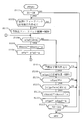
- FIG. 4 is a flowchart showing a fuel injection amount calculation routine.
- the fuel injection amount calculation routine is stored in advance in the ROM of the ECU 14, and is executed by the ECU 14 when the internal combustion engine 1 is started (when the ignition switch is turned on).
- the ECU 14 determines whether or not an execution condition for the air-fuel ratio feedback control is satisfied.
- the execution condition of the air-fuel ratio feedback control is that the A / F sensor 9 is activated.
- the activity of the A / F sensor 9 is that the temperature of the A / F sensor 9 is equal to or higher than the activation temperature, and the cooling water temperature is a predetermined temperature (cooling water temperature when the temperature of the A / F sensor 9 is equal to or higher than the activation temperature). It is determined on the condition that the exhaust gas temperature downstream from the A / F sensor 9 is equal to or higher than a predetermined temperature (exhaust temperature when the temperature of the A / F sensor 9 is equal to or higher than the activation temperature).
- the ECU 14 starts executing the air-fuel ratio feedback control.
- the ECU 14 executes air-fuel ratio feedback control according to a separately set subroutine.
- the ECU 14 first calculates the air-fuel ratio feedback correction value efaf based on the difference between the air-fuel ratio detected by the A / F sensor 9 and the target air-fuel ratio.
- the ECU 14 calculates the air-fuel ratio feedback correction coefficient ekaf by substituting the air-fuel ratio feedback correction value efaf into the equation (2).
- the ECU 14 calculates the fuel injection amount (fuel injection time) etau by substituting the air-fuel ratio feedback correction coefficient ekaf into the equation (3).
- the subroutine is repeatedly executed by the ECU 14 as long as the air-fuel ratio feedback control execution condition is satisfied.
- the control means according to the present invention is realized.
- the ECU 14 determines whether or not the absolute value (
- the ECU 14 proceeds to S106 after executing the process of S105, and subtracts the predetermined value a from the air-fuel ratio feedback correction value efaf.
- the ECU 14 finishes executing the process of S106, the ECU 14 returns to S104. That is, the ECU 14 repeatedly executes the processes of S105 and S106 until the absolute value of the air-fuel ratio feedback correction value efaf becomes less than the first threshold th1.
- the ECU 14 makes a negative determination (
- the ECU 14 determines whether a learning condition (air-fuel ratio learning condition) of the air-fuel ratio learning value efgaf is satisfied.
- the air-fuel ratio learning condition is that the internal combustion engine 1 is in a warm-up state (cooling water temperature is equal to or higher than the warm-up determination temperature), and the state where the magnitude of the air-fuel ratio feedback correction coefficient ekaf deviates from a predetermined range. It is continuing for a certain period. If a negative determination is made in S107, the ECU 14 repeatedly executes the process of S107.
- the ECU 14 proceeds to S108.
- the ECU 14 starts a learning process for the air-fuel ratio learned value efgaf.
- the ECU 14 executes a learning process of the air-fuel ratio learning value efgaf by a known method.
- the ECU 14 calculates an average value efgafave of the air-fuel ratio learned value efgaf in the entire operation region of the internal combustion engine 1, and determines whether or not the absolute value of the average value efgafave is equal to or greater than a second threshold th2. If a negative determination is made in S110 (
- the ECU 14 proceeds to S112 after executing the processing of S111, and subtracts the predetermined value b from the air-fuel ratio learning value efgaf. At this time, the ECU 14 performs a subtraction process on the predetermined value b for all the air-fuel ratio learning values efgaf set for each operating region of the internal combustion engine 1.
- ECU14 will complete
- determine whether the ignition switch was turned off (IG OFF). If a negative determination is made in S113, the ECU 14 executes the processes after S107 (or the processes after S104) again. On the other hand, if a positive determination is made in S113, the ECU 14 ends the execution of this routine.
- correction means according to the present invention is realized by the ECU 14 executing the process of S105 or S111.
- the fuel injection amount (fuel injection time) etau changes after the change.
- the ECU 14 corrects the ignition timing according to the inert gas concentration of CNG when the properties of CNG change. For example, the ECU 14 performs correction so that the ignition timing is advanced (advanced) when the inert gas concentration of CNG is high compared to when it is low.
- the inert gas concentration of CNG is proportional to the magnitude of the inert gas concentration learning value eknco2 described above.
- the ECU 14 may correct so that the ignition timing is earlier when the learned inert gas concentration value eknco2 is larger than when it is small.
- the combustion end timing of the air-fuel mixture can be set to a desired timing even when the CNG property changes. As a result, it is possible to avoid a situation in which the output of the internal combustion engine 1 decreases or the temperature of the exhaust gas increases unnecessarily.
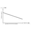
- the ECU 14 may correct the EGR gas amount in place of the ignition timing in an internal combustion engine equipped with an EGR system. For example, as shown in FIG. 7, the ECU 14 may correct the opening degree of the EGR valve so that the amount of EGR gas is smaller when the inert gas concentration learned value eknco2 is large than when it is small.
- the ECU 14 determines that the cylinder 3 The variable valve mechanism may be controlled so that the amount of burned gas (internal EGR gas) remaining in the interior decreases.
- the amount of EGR gas in the cylinder 3 is adjusted by the above-described various methods, even if the inert gas concentration of CNG changes, the change in the concentration of the inert gas contained in the mixture is suppressed. be able to. As a result, when the inert gas concentration of CNG changes, it can suppress that the combustion rate of air-fuel
- the ECU 14 corrects the ignition timing and the EGR gas amount so that the speed at which the intake air flows into the cylinder 3 is changed instead of correcting the ignition timing and the EGR gas amount.
- You may control.
- the ECU 14 may control the variable valve mechanism so that the flow rate of the intake air is faster when the learned inert gas concentration value eknco2 is larger than when it is smaller.
- the flow rate of the intake air is increased, the flame propagation speed when the air-fuel mixture burns can be increased.
- the inert gas concentration of CNG becomes high, it is possible to suppress a decrease in the combustion rate of the air-fuel mixture.
Landscapes
- Engineering & Computer Science (AREA)
- Chemical & Material Sciences (AREA)
- Combustion & Propulsion (AREA)
- Mechanical Engineering (AREA)
- General Engineering & Computer Science (AREA)
- Output Control And Ontrol Of Special Type Engine (AREA)
- Electrical Control Of Air Or Fuel Supplied To Internal-Combustion Engine (AREA)
- Combined Controls Of Internal Combustion Engines (AREA)
Abstract
Description
内燃機関で燃焼された混合気の空燃比と目標空燃比の偏差に基づいて燃料噴射量を補正するための空燃比フィードバック制御を実施する制御手段と、
前記空燃比フィードバック制御による補正値の絶対値が閾値以上であるときに、混合気の燃焼状態に係わる制御パラメータを補正する補正手段と、
を備えるようにした。
内燃機関で燃焼される混合気の空燃比と目標空燃比の偏差に応じて燃料噴射量を補正するめの空燃比フィードバック制御を実行する制御手段と、
前記空燃比フィードバック制御による補正値の絶対値が閾値未満であるときに、前記空燃比フィードバック制御による補正値の学習制御を実行する学習手段と、
前記空燃比フィードバック制御による補正値の絶対値が閾値以上であるときに、前記空燃比フィードバック制御により求められる燃料噴射量を補正する補正手段と、
を備えるようにしてもよい。
先ず、本発明の第1の実施例について図1乃至図4に基づいて説明する。図1は、本発明を適用する車輌の概略構成を示す図である。図1に示す車両は、CNGを使用する内燃機関が搭載された車両である。
etau=etp*ekaf*k・・・(1)
ekaf=(efaf+efgaf+100)/100・・・(2)
etau=etp*ekaf*ekin*k・・・(3)
ekin=(eknco2+100)/100・・・(4)
次に、本発明の第2の実施例について図5乃至図7に基づいて説明する。ここでは、前述した第1の実施例と異なる構成について説明し、同様の構成については説明を省略する。
2 燃料タンク
3 気筒
4 燃料噴射弁
5 吸気通路
6 排気通路
7 吸気絞り弁
8 吸気温度センサ
9 A/Fセンサ
10 圧力センサ
11 燃料供給管
12 充填口
13 インレットパイプ
14 ECU
100 車両
Claims (6)
- 圧縮天然ガスを使用する内燃機関の制御システムにおいて、
内燃機関で燃焼された混合気の空燃比と目標空燃比の偏差に基づいて燃料噴射量を補正するための空燃比フィードバック制御を実施する制御手段と、
前記空燃比フィードバック制御による補正値の絶対値が閾値以上であるときに、混合気の燃焼状態に係わる制御パラメータを補正する補正手段と、
を備える内燃機関の制御システム。 - 請求項1において、前記制御パラメータは、燃料噴射量であり、
前記制御手段は、前記空燃比フィードバック制御を実行する際に、内燃機関で燃焼された混合気の空燃比と目標空燃比の偏差に応じて決定される補正項である第1補正値と、圧縮天然ガスの性状に応じて決定される補正項である第2補正値を用いて燃料噴射量を決定し、
前記補正手段は、前記第1補正値の絶対値が前記閾値以上であるときに、前記第2補正値を変更することにより、燃料噴射量を補正する内燃機関の制御システム。 - 請求項2において、前記補正手段は、圧縮天然ガスに含まれる不活性ガス濃度が高いときは低いときに比べ、理論空燃比が低くなると同時にウォッペ指数が小さくなる関係に基づいて、前記第2補正値を変更する内燃機関の制御システム。
- 請求項2又は3において、前記制御手段は、前記補正手段により第2補正値が変更されたときに、第2補正値の変更分を前記第1補正値から減算する内燃機関の制御システム。
- 請求項2乃至4において、前記補正手段による燃料噴射量の補正は、前記空燃比フィードバック制御による補正値の学習制御に優先して実行される内燃機関の制御システム。
- 内燃機関で燃焼される混合気の空燃比と目標空燃比の偏差に応じて燃料噴射量を補正するめの空燃比フィードバック制御を実行する制御手段と、
前記空燃比フィードバック制御による補正値の絶対値が閾値未満であるときに、前記空燃比フィードバック制御による補正値の学習制御を実行する学習手段と、
前記空燃比フィードバック制御による補正値の絶対値が閾値以上であるときに、前記空燃比フィードバック制御により求められた燃料噴射量を補正する補正手段と、
を備える内燃機関の制御システム。
Priority Applications (6)
| Application Number | Priority Date | Filing Date | Title |
|---|---|---|---|
| EP11876090.9A EP2784291A4 (en) | 2011-11-22 | 2011-11-22 | CONTROL SYSTEM FOR A COMBUSTION ENGINE |
| CN201180074974.9A CN103946517B (zh) | 2011-11-22 | 2011-11-22 | 内燃机的控制系统 |
| JP2013545687A JP5817842B2 (ja) | 2011-11-22 | 2011-11-22 | 内燃機関の制御システム |
| US14/359,648 US9562489B2 (en) | 2011-11-22 | 2011-11-22 | Control system for internal combustion engine |
| PCT/JP2011/076918 WO2013076811A1 (ja) | 2011-11-22 | 2011-11-22 | 内燃機関の制御システム |
| BR112014012330A BR112014012330A2 (pt) | 2011-11-22 | 2011-11-22 | sistema de controle para motor de combustão interna |
Applications Claiming Priority (1)
| Application Number | Priority Date | Filing Date | Title |
|---|---|---|---|
| PCT/JP2011/076918 WO2013076811A1 (ja) | 2011-11-22 | 2011-11-22 | 内燃機関の制御システム |
Publications (1)
| Publication Number | Publication Date |
|---|---|
| WO2013076811A1 true WO2013076811A1 (ja) | 2013-05-30 |
Family
ID=48469291
Family Applications (1)
| Application Number | Title | Priority Date | Filing Date |
|---|---|---|---|
| PCT/JP2011/076918 Ceased WO2013076811A1 (ja) | 2011-11-22 | 2011-11-22 | 内燃機関の制御システム |
Country Status (6)
| Country | Link |
|---|---|
| US (1) | US9562489B2 (ja) |
| EP (1) | EP2784291A4 (ja) |
| JP (1) | JP5817842B2 (ja) |
| CN (1) | CN103946517B (ja) |
| BR (1) | BR112014012330A2 (ja) |
| WO (1) | WO2013076811A1 (ja) |
Cited By (5)
| Publication number | Priority date | Publication date | Assignee | Title |
|---|---|---|---|---|
| WO2015079310A1 (en) * | 2013-11-29 | 2015-06-04 | Toyota Jidosha Kabushiki Kaisha | Fuel injection control device |
| WO2015114444A1 (en) | 2014-01-31 | 2015-08-06 | Toyota Jidosha Kabushiki Kaisha | Control system and control method for internal combustion engine |
| CN105114196A (zh) * | 2014-05-09 | 2015-12-02 | Ge延巴赫两合无限公司 | 内燃机和用于运行内燃机的方法 |
| WO2016006201A1 (en) | 2014-06-30 | 2016-01-14 | Toyota Jidosha Kabushiki Kaisha | Air fuel ratio control for an internal combustion engine that can be operated with fuels at different properties |
| DE102014216874A1 (de) * | 2014-08-25 | 2016-02-25 | Mtu Friedrichshafen Gmbh | Verfahren zum Betreiben einer Brennkraftmaschine und Brennkraftmaschine |
Families Citing this family (5)
| Publication number | Priority date | Publication date | Assignee | Title |
|---|---|---|---|---|
| DE102017000860B4 (de) | 2016-02-03 | 2025-01-23 | Cummins Inc. | Virtueller Gasqualitätssensor für einen Verbrennungsmotor |
| EP3680477B1 (en) * | 2017-09-06 | 2025-11-26 | IHI Corporation | Engine control system |
| JP2019196718A (ja) * | 2018-05-08 | 2019-11-14 | いすゞ自動車株式会社 | 内燃機関及び内燃機関の制御方法 |
| EP4115067A4 (en) * | 2020-03-02 | 2024-12-25 | InPro/Seal LLC | NATURAL GAS ENGINES WITH FUEL QUALITY DETERMINATION |
| CN112392618B (zh) * | 2020-11-18 | 2023-05-23 | 潍柴动力股份有限公司 | 一种燃料喷射加电时间修正方法和装置 |
Citations (3)
| Publication number | Priority date | Publication date | Assignee | Title |
|---|---|---|---|---|
| JP2001193571A (ja) * | 2000-01-12 | 2001-07-17 | Hitachi Ltd | 気体燃料エンジンの診断装置 |
| JP2002357150A (ja) * | 2001-05-30 | 2002-12-13 | Suzuki Motor Corp | Cngエンジンの燃料噴射制御装置 |
| JP2004346911A (ja) | 2003-05-26 | 2004-12-09 | Toyota Motor Corp | Cngエンジンの燃料性状別制御方法 |
Family Cites Families (13)
| Publication number | Priority date | Publication date | Assignee | Title |
|---|---|---|---|---|
| US4729359A (en) | 1985-06-28 | 1988-03-08 | Japan Electronic Control Systems Co., Ltd. | Learning and control apparatus for electronically controlled internal combustion engine |
| JP3581762B2 (ja) | 1996-06-20 | 2004-10-27 | トヨタ自動車株式会社 | 内燃機関の空燃比制御装置 |
| JP3191691B2 (ja) * | 1996-08-13 | 2001-07-23 | トヨタ自動車株式会社 | ガス燃料内燃機関の制御装置 |
| JP3681041B2 (ja) * | 1999-02-16 | 2005-08-10 | 三菱電機株式会社 | 筒内噴射式内燃機関の制御装置 |
| JP4365553B2 (ja) * | 2001-12-26 | 2009-11-18 | 株式会社日立製作所 | エンジンの燃料制御装置及びアイドリング時の空燃比制御方法 |
| JP4228631B2 (ja) * | 2002-08-30 | 2009-02-25 | トヨタ自動車株式会社 | 内燃機関の制御装置 |
| JP2005220860A (ja) * | 2004-02-09 | 2005-08-18 | Nikki Co Ltd | ガスエンジンの空燃比制御方法および装置 |
| US7044103B2 (en) * | 2004-08-16 | 2006-05-16 | Dresser, Inc. | Fuel quantity modulation in pilot ignited engines |
| JP2007046517A (ja) * | 2005-08-09 | 2007-02-22 | Mitsubishi Electric Corp | 内燃機関の制御装置 |
| JP4755155B2 (ja) * | 2007-08-30 | 2011-08-24 | 三菱重工業株式会社 | ガスエンジンの統合制御方法及び装置 |
| JP4818382B2 (ja) * | 2009-03-09 | 2011-11-16 | 三菱電機株式会社 | 内燃機関の燃料噴射装置 |
| US8214129B2 (en) * | 2009-05-13 | 2012-07-03 | Ford Global Technologies, Llc | Distinguishing the fuel admitted to a fuel system |
| WO2014094156A1 (en) * | 2012-12-22 | 2014-06-26 | Westport Power Inc. | Air-fuel ratio control in a multi-fuel internal combustion engine |
-
2011
- 2011-11-22 WO PCT/JP2011/076918 patent/WO2013076811A1/ja not_active Ceased
- 2011-11-22 US US14/359,648 patent/US9562489B2/en not_active Expired - Fee Related
- 2011-11-22 BR BR112014012330A patent/BR112014012330A2/pt active Search and Examination
- 2011-11-22 EP EP11876090.9A patent/EP2784291A4/en not_active Withdrawn
- 2011-11-22 CN CN201180074974.9A patent/CN103946517B/zh not_active Expired - Fee Related
- 2011-11-22 JP JP2013545687A patent/JP5817842B2/ja not_active Expired - Fee Related
Patent Citations (3)
| Publication number | Priority date | Publication date | Assignee | Title |
|---|---|---|---|---|
| JP2001193571A (ja) * | 2000-01-12 | 2001-07-17 | Hitachi Ltd | 気体燃料エンジンの診断装置 |
| JP2002357150A (ja) * | 2001-05-30 | 2002-12-13 | Suzuki Motor Corp | Cngエンジンの燃料噴射制御装置 |
| JP2004346911A (ja) | 2003-05-26 | 2004-12-09 | Toyota Motor Corp | Cngエンジンの燃料性状別制御方法 |
Non-Patent Citations (1)
| Title |
|---|
| See also references of EP2784291A4 |
Cited By (20)
| Publication number | Priority date | Publication date | Assignee | Title |
|---|---|---|---|---|
| WO2015079310A1 (en) * | 2013-11-29 | 2015-06-04 | Toyota Jidosha Kabushiki Kaisha | Fuel injection control device |
| JP2015105618A (ja) * | 2013-11-29 | 2015-06-08 | トヨタ自動車株式会社 | 燃料噴射制御装置 |
| WO2015114444A1 (en) | 2014-01-31 | 2015-08-06 | Toyota Jidosha Kabushiki Kaisha | Control system and control method for internal combustion engine |
| CN105940206B (zh) * | 2014-01-31 | 2019-01-18 | 丰田自动车株式会社 | 用于内燃发动机的控制系统和控制方法 |
| US9926864B2 (en) | 2014-01-31 | 2018-03-27 | Toyota Jidosha Kabushiki Kaisha | Control system and control method for internal combustion engine |
| CN105940206A (zh) * | 2014-01-31 | 2016-09-14 | 丰田自动车株式会社 | 用于内燃发动机的控制系统和控制方法 |
| CN105114196A (zh) * | 2014-05-09 | 2015-12-02 | Ge延巴赫两合无限公司 | 内燃机和用于运行内燃机的方法 |
| CN111502837A (zh) * | 2014-05-09 | 2020-08-07 | Ge延巴赫两合无限公司 | 内燃机和用于运行内燃机的方法 |
| EP2990631A1 (de) * | 2014-05-09 | 2016-03-02 | GE Jenbacher GmbH & Co. OG | Verbrennungsmotor und verfahren zum betrieb desselben |
| AT515769A3 (de) * | 2014-05-09 | 2018-01-15 | Ge Jenbacher Gmbh & Co Og | Verbrennungsmotor und Verfahren zum Betrieb desselben |
| CN106460697A (zh) * | 2014-06-30 | 2017-02-22 | 丰田自动车株式会社 | 可以使用不同性能的燃料工作的内燃机的空气‑燃料比控制 |
| US10138837B2 (en) | 2014-06-30 | 2018-11-27 | Toyota Jidosha Kabushiki Kaisha | Air fuel ratio control for an internal combustion engine that can be operated with fuels at different properties |
| JP2016027256A (ja) * | 2014-06-30 | 2016-02-18 | トヨタ自動車株式会社 | 内燃機関の制御システム |
| CN106460697B (zh) * | 2014-06-30 | 2019-08-27 | 丰田自动车株式会社 | 可以使用不同性能的燃料工作的内燃机的空气-燃料比控制 |
| WO2016006201A1 (en) | 2014-06-30 | 2016-01-14 | Toyota Jidosha Kabushiki Kaisha | Air fuel ratio control for an internal combustion engine that can be operated with fuels at different properties |
| DE112015003081B4 (de) | 2014-06-30 | 2021-11-04 | Toyota Jidosha Kabushiki Kaisha | Luft-Kraftstoff-Verhältnis-Steuerung für einen Motor mit interner Verbrennung, der mit Kraftstoffen bei verschiedenen Eigenschaften betrieben werden kann |
| WO2016030002A1 (de) * | 2014-08-25 | 2016-03-03 | Mtu Friedrichshafen Gmbh | Verfahren zum betreiben einer brennkraftmaschine und brennkraftmaschine |
| DE102014216874B4 (de) * | 2014-08-25 | 2018-02-22 | Mtu Friedrichshafen Gmbh | Verfahren zum Betreiben einer Brennkraftmaschine und Brennkraftmaschine |
| DE102014216874A1 (de) * | 2014-08-25 | 2016-02-25 | Mtu Friedrichshafen Gmbh | Verfahren zum Betreiben einer Brennkraftmaschine und Brennkraftmaschine |
| US10180110B2 (en) | 2014-08-25 | 2019-01-15 | Mtu Friedrichshafen Gmbh | Method for operating an internal combustion engine based on a characteristic value determined from a lamda value, and internal combustion engine |
Also Published As
| Publication number | Publication date |
|---|---|
| US20140303876A1 (en) | 2014-10-09 |
| US9562489B2 (en) | 2017-02-07 |
| CN103946517B (zh) | 2016-08-31 |
| BR112014012330A2 (pt) | 2017-05-30 |
| JPWO2013076811A1 (ja) | 2015-04-27 |
| CN103946517A (zh) | 2014-07-23 |
| EP2784291A4 (en) | 2015-05-27 |
| JP5817842B2 (ja) | 2015-11-18 |
| EP2784291A1 (en) | 2014-10-01 |
Similar Documents
| Publication | Publication Date | Title |
|---|---|---|
| JP5817842B2 (ja) | 内燃機関の制御システム | |
| JP4089601B2 (ja) | 内燃機関の燃料噴射制御装置 | |
| EP1754874A1 (en) | Method and apparatus for controlling an internal combustion engine | |
| JP2011027059A (ja) | エンジンの制御装置 | |
| US9759153B2 (en) | Control apparatus for internal combustion engine | |
| JP5124522B2 (ja) | 圧縮自己着火式内燃機関の制御装置 | |
| JP2009185628A (ja) | 内燃機関の燃料噴射制御システム | |
| US9109524B2 (en) | Controller for internal combustion engine | |
| CN106460697B (zh) | 可以使用不同性能的燃料工作的内燃机的空气-燃料比控制 | |
| CN1965156A (zh) | 用于氢添加内燃机的控制系统 | |
| JP2004108231A (ja) | 内燃機関の燃料噴射制御装置 | |
| JP5792611B2 (ja) | 内燃機関の制御システム | |
| JP6209982B2 (ja) | 内燃機関の制御システム | |
| US20140318500A1 (en) | Fuel property determination system for vehicle | |
| JP5260770B2 (ja) | エンジンの制御装置 | |
| JP2020190214A (ja) | 蒸発燃料処理装置 | |
| JP4329610B2 (ja) | 内燃機関の燃料噴射量制御装置 | |
| JP2011157837A (ja) | 内燃機関の制御装置 | |
| JP2009144568A (ja) | 内燃機関の空燃比制御装置 | |
| JP2010090870A (ja) | 内燃機関のブローバイガス処理装置 | |
| JP2011117341A (ja) | 内燃機関装置、それを備えた車両および内燃機関装置の制御方法 | |
| JP2016003598A (ja) | 内燃機関の制御システム | |
| JP2006057512A (ja) | 内燃機関の制御装置 | |
| JP2012184689A (ja) | 内燃機関の制御装置 | |
| JP2017014899A (ja) | 内燃機関の制御装置 |
Legal Events
| Date | Code | Title | Description |
|---|---|---|---|
| 121 | Ep: the epo has been informed by wipo that ep was designated in this application |
Ref document number: 11876090 Country of ref document: EP Kind code of ref document: A1 |
|
| DPE1 | Request for preliminary examination filed after expiration of 19th month from priority date (pct application filed from 20040101) | ||
| ENP | Entry into the national phase |
Ref document number: 2013545687 Country of ref document: JP Kind code of ref document: A |
|
| WWE | Wipo information: entry into national phase |
Ref document number: 14359648 Country of ref document: US |
|
| NENP | Non-entry into the national phase |
Ref country code: DE |
|
| WWE | Wipo information: entry into national phase |
Ref document number: 2011876090 Country of ref document: EP |
|
| REG | Reference to national code |
Ref country code: BR Ref legal event code: B01A Ref document number: 112014012330 Country of ref document: BR |
|
| ENP | Entry into the national phase |
Ref document number: 112014012330 Country of ref document: BR Kind code of ref document: A2 Effective date: 20140521 |