WO2013077046A1 - 生体用金属製多孔質板 - Google Patents
生体用金属製多孔質板 Download PDFInfo
- Publication number
- WO2013077046A1 WO2013077046A1 PCT/JP2012/070993 JP2012070993W WO2013077046A1 WO 2013077046 A1 WO2013077046 A1 WO 2013077046A1 JP 2012070993 W JP2012070993 W JP 2012070993W WO 2013077046 A1 WO2013077046 A1 WO 2013077046A1
- Authority
- WO
- WIPO (PCT)
- Prior art keywords
- porous plate
- implant material
- metal porous
- opening
- slurry
- Prior art date
- Legal status (The legal status is an assumption and is not a legal conclusion. Google has not performed a legal analysis and makes no representation as to the accuracy of the status listed.)
- Ceased
Links
Images

Classifications
-
- A—HUMAN NECESSITIES
- A61—MEDICAL OR VETERINARY SCIENCE; HYGIENE
- A61L—METHODS OR APPARATUS FOR STERILISING MATERIALS OR OBJECTS IN GENERAL; DISINFECTION, STERILISATION OR DEODORISATION OF AIR; CHEMICAL ASPECTS OF BANDAGES, DRESSINGS, ABSORBENT PADS OR SURGICAL ARTICLES; MATERIALS FOR BANDAGES, DRESSINGS, ABSORBENT PADS OR SURGICAL ARTICLES
- A61L31/00—Materials for other surgical articles, e.g. stents, stent-grafts, shunts, surgical drapes, guide wires, materials for adhesion prevention, occluding devices, surgical gloves, tissue fixation devices
- A61L31/14—Materials characterised by their function or physical properties, e.g. injectable or lubricating compositions, shape-memory materials, surface modified materials
- A61L31/146—Porous materials, e.g. foams or sponges
-
- A—HUMAN NECESSITIES
- A61—MEDICAL OR VETERINARY SCIENCE; HYGIENE
- A61F—FILTERS IMPLANTABLE INTO BLOOD VESSELS; PROSTHESES; DEVICES PROVIDING PATENCY TO, OR PREVENTING COLLAPSING OF, TUBULAR STRUCTURES OF THE BODY, e.g. STENTS; ORTHOPAEDIC, NURSING OR CONTRACEPTIVE DEVICES; FOMENTATION; TREATMENT OR PROTECTION OF EYES OR EARS; BANDAGES, DRESSINGS OR ABSORBENT PADS; FIRST-AID KITS
- A61F2/00—Filters implantable into blood vessels; Prostheses, i.e. artificial substitutes or replacements for parts of the body; Appliances for connecting them with the body; Devices providing patency to, or preventing collapsing of, tubular structures of the body, e.g. stents
- A61F2/02—Prostheses implantable into the body
- A61F2/30—Joints
- A61F2/30767—Special external or bone-contacting surface, e.g. coating for improving bone ingrowth
- A61F2/30907—Nets or sleeves applied to surface of prostheses or in cement
-
- A—HUMAN NECESSITIES
- A61—MEDICAL OR VETERINARY SCIENCE; HYGIENE
- A61L—METHODS OR APPARATUS FOR STERILISING MATERIALS OR OBJECTS IN GENERAL; DISINFECTION, STERILISATION OR DEODORISATION OF AIR; CHEMICAL ASPECTS OF BANDAGES, DRESSINGS, ABSORBENT PADS OR SURGICAL ARTICLES; MATERIALS FOR BANDAGES, DRESSINGS, ABSORBENT PADS OR SURGICAL ARTICLES
- A61L27/00—Materials for grafts or prostheses or for coating grafts or prostheses
- A61L27/02—Inorganic materials
- A61L27/04—Metals or alloys
-
- A—HUMAN NECESSITIES
- A61—MEDICAL OR VETERINARY SCIENCE; HYGIENE
- A61L—METHODS OR APPARATUS FOR STERILISING MATERIALS OR OBJECTS IN GENERAL; DISINFECTION, STERILISATION OR DEODORISATION OF AIR; CHEMICAL ASPECTS OF BANDAGES, DRESSINGS, ABSORBENT PADS OR SURGICAL ARTICLES; MATERIALS FOR BANDAGES, DRESSINGS, ABSORBENT PADS OR SURGICAL ARTICLES
- A61L27/00—Materials for grafts or prostheses or for coating grafts or prostheses
- A61L27/50—Materials characterised by their function or physical properties, e.g. injectable or lubricating compositions, shape-memory materials, surface modified materials
-
- A—HUMAN NECESSITIES
- A61—MEDICAL OR VETERINARY SCIENCE; HYGIENE
- A61L—METHODS OR APPARATUS FOR STERILISING MATERIALS OR OBJECTS IN GENERAL; DISINFECTION, STERILISATION OR DEODORISATION OF AIR; CHEMICAL ASPECTS OF BANDAGES, DRESSINGS, ABSORBENT PADS OR SURGICAL ARTICLES; MATERIALS FOR BANDAGES, DRESSINGS, ABSORBENT PADS OR SURGICAL ARTICLES
- A61L27/00—Materials for grafts or prostheses or for coating grafts or prostheses
- A61L27/50—Materials characterised by their function or physical properties, e.g. injectable or lubricating compositions, shape-memory materials, surface modified materials
- A61L27/56—Porous materials, e.g. foams or sponges
-
- A—HUMAN NECESSITIES
- A61—MEDICAL OR VETERINARY SCIENCE; HYGIENE
- A61L—METHODS OR APPARATUS FOR STERILISING MATERIALS OR OBJECTS IN GENERAL; DISINFECTION, STERILISATION OR DEODORISATION OF AIR; CHEMICAL ASPECTS OF BANDAGES, DRESSINGS, ABSORBENT PADS OR SURGICAL ARTICLES; MATERIALS FOR BANDAGES, DRESSINGS, ABSORBENT PADS OR SURGICAL ARTICLES
- A61L31/00—Materials for other surgical articles, e.g. stents, stent-grafts, shunts, surgical drapes, guide wires, materials for adhesion prevention, occluding devices, surgical gloves, tissue fixation devices
- A61L31/02—Inorganic materials
- A61L31/022—Metals or alloys
-
- B—PERFORMING OPERATIONS; TRANSPORTING
- B22—CASTING; POWDER METALLURGY
- B22F—WORKING METALLIC POWDER; MANUFACTURE OF ARTICLES FROM METALLIC POWDER; MAKING METALLIC POWDER; APPARATUS OR DEVICES SPECIALLY ADAPTED FOR METALLIC POWDER
- B22F10/00—Additive manufacturing of workpieces or articles from metallic powder
- B22F10/20—Direct sintering or melting
- B22F10/28—Powder bed fusion, e.g. selective laser melting [SLM] or electron beam melting [EBM]
-
- B—PERFORMING OPERATIONS; TRANSPORTING
- B22—CASTING; POWDER METALLURGY
- B22F—WORKING METALLIC POWDER; MANUFACTURE OF ARTICLES FROM METALLIC POWDER; MAKING METALLIC POWDER; APPARATUS OR DEVICES SPECIALLY ADAPTED FOR METALLIC POWDER
- B22F5/00—Manufacture of workpieces or articles from metallic powder characterised by the special shape of the product
- B22F5/006—Manufacture of workpieces or articles from metallic powder characterised by the special shape of the product of flat products, e.g. sheets
-
- B—PERFORMING OPERATIONS; TRANSPORTING
- B22—CASTING; POWDER METALLURGY
- B22F—WORKING METALLIC POWDER; MANUFACTURE OF ARTICLES FROM METALLIC POWDER; MAKING METALLIC POWDER; APPARATUS OR DEVICES SPECIALLY ADAPTED FOR METALLIC POWDER
- B22F7/00—Manufacture of composite layers, workpieces, or articles, comprising metallic powder, by sintering the powder, with or without compacting wherein at least one part is obtained by sintering or compression
- B22F7/002—Manufacture of composite layers, workpieces, or articles, comprising metallic powder, by sintering the powder, with or without compacting wherein at least one part is obtained by sintering or compression of porous nature
- B22F7/004—Manufacture of composite layers, workpieces, or articles, comprising metallic powder, by sintering the powder, with or without compacting wherein at least one part is obtained by sintering or compression of porous nature comprising at least one non-porous part
-
- B—PERFORMING OPERATIONS; TRANSPORTING
- B23—MACHINE TOOLS; METAL-WORKING NOT OTHERWISE PROVIDED FOR
- B23K—SOLDERING OR UNSOLDERING; WELDING; CLADDING OR PLATING BY SOLDERING OR WELDING; CUTTING BY APPLYING HEAT LOCALLY, e.g. FLAME CUTTING; WORKING BY LASER BEAM
- B23K35/00—Rods, electrodes, materials, or media, for use in soldering, welding, or cutting
- B23K35/02—Rods, electrodes, materials, or media, for use in soldering, welding, or cutting characterised by mechanical features, e.g. shape
- B23K35/0222—Rods, electrodes, materials, or media, for use in soldering, welding, or cutting characterised by mechanical features, e.g. shape for use in soldering or brazing
- B23K35/0244—Powders, particles or spheres; Preforms made therefrom
-
- B—PERFORMING OPERATIONS; TRANSPORTING
- B23—MACHINE TOOLS; METAL-WORKING NOT OTHERWISE PROVIDED FOR
- B23K—SOLDERING OR UNSOLDERING; WELDING; CLADDING OR PLATING BY SOLDERING OR WELDING; CUTTING BY APPLYING HEAT LOCALLY, e.g. FLAME CUTTING; WORKING BY LASER BEAM
- B23K35/00—Rods, electrodes, materials, or media, for use in soldering, welding, or cutting
- B23K35/02—Rods, electrodes, materials, or media, for use in soldering, welding, or cutting characterised by mechanical features, e.g. shape
- B23K35/0222—Rods, electrodes, materials, or media, for use in soldering, welding, or cutting characterised by mechanical features, e.g. shape for use in soldering or brazing
- B23K35/0244—Powders, particles or spheres; Preforms made therefrom
- B23K35/025—Pastes, creams or slurries
-
- C—CHEMISTRY; METALLURGY
- C22—METALLURGY; FERROUS OR NON-FERROUS ALLOYS; TREATMENT OF ALLOYS OR NON-FERROUS METALS
- C22C—ALLOYS
- C22C14/00—Alloys based on titanium
-
- C—CHEMISTRY; METALLURGY
- C22—METALLURGY; FERROUS OR NON-FERROUS ALLOYS; TREATMENT OF ALLOYS OR NON-FERROUS METALS
- C22C—ALLOYS
- C22C19/00—Alloys based on nickel or cobalt
- C22C19/07—Alloys based on nickel or cobalt based on cobalt
-
- A—HUMAN NECESSITIES
- A61—MEDICAL OR VETERINARY SCIENCE; HYGIENE
- A61F—FILTERS IMPLANTABLE INTO BLOOD VESSELS; PROSTHESES; DEVICES PROVIDING PATENCY TO, OR PREVENTING COLLAPSING OF, TUBULAR STRUCTURES OF THE BODY, e.g. STENTS; ORTHOPAEDIC, NURSING OR CONTRACEPTIVE DEVICES; FOMENTATION; TREATMENT OR PROTECTION OF EYES OR EARS; BANDAGES, DRESSINGS OR ABSORBENT PADS; FIRST-AID KITS
- A61F2/00—Filters implantable into blood vessels; Prostheses, i.e. artificial substitutes or replacements for parts of the body; Appliances for connecting them with the body; Devices providing patency to, or preventing collapsing of, tubular structures of the body, e.g. stents
- A61F2/02—Prostheses implantable into the body
- A61F2/30—Joints
- A61F2/30767—Special external or bone-contacting surface, e.g. coating for improving bone ingrowth
- A61F2/30907—Nets or sleeves applied to surface of prostheses or in cement
- A61F2002/30909—Nets
-
- A—HUMAN NECESSITIES
- A61—MEDICAL OR VETERINARY SCIENCE; HYGIENE
- A61F—FILTERS IMPLANTABLE INTO BLOOD VESSELS; PROSTHESES; DEVICES PROVIDING PATENCY TO, OR PREVENTING COLLAPSING OF, TUBULAR STRUCTURES OF THE BODY, e.g. STENTS; ORTHOPAEDIC, NURSING OR CONTRACEPTIVE DEVICES; FOMENTATION; TREATMENT OR PROTECTION OF EYES OR EARS; BANDAGES, DRESSINGS OR ABSORBENT PADS; FIRST-AID KITS
- A61F2/00—Filters implantable into blood vessels; Prostheses, i.e. artificial substitutes or replacements for parts of the body; Appliances for connecting them with the body; Devices providing patency to, or preventing collapsing of, tubular structures of the body, e.g. stents
- A61F2/02—Prostheses implantable into the body
- A61F2/30—Joints
- A61F2/30767—Special external or bone-contacting surface, e.g. coating for improving bone ingrowth
- A61F2/30907—Nets or sleeves applied to surface of prostheses or in cement
- A61F2002/30909—Nets
- A61F2002/30914—Details of the mesh structure, e.g. disposition of the woven warp and weft wires
-
- A—HUMAN NECESSITIES
- A61—MEDICAL OR VETERINARY SCIENCE; HYGIENE
- A61F—FILTERS IMPLANTABLE INTO BLOOD VESSELS; PROSTHESES; DEVICES PROVIDING PATENCY TO, OR PREVENTING COLLAPSING OF, TUBULAR STRUCTURES OF THE BODY, e.g. STENTS; ORTHOPAEDIC, NURSING OR CONTRACEPTIVE DEVICES; FOMENTATION; TREATMENT OR PROTECTION OF EYES OR EARS; BANDAGES, DRESSINGS OR ABSORBENT PADS; FIRST-AID KITS
- A61F2310/00—Prostheses classified in A61F2/28 or A61F2/30 - A61F2/44 being constructed from or coated with a particular material
- A61F2310/00005—The prosthesis being constructed from a particular material
- A61F2310/00011—Metals or alloys
-
- A—HUMAN NECESSITIES
- A61—MEDICAL OR VETERINARY SCIENCE; HYGIENE
- A61L—METHODS OR APPARATUS FOR STERILISING MATERIALS OR OBJECTS IN GENERAL; DISINFECTION, STERILISATION OR DEODORISATION OF AIR; CHEMICAL ASPECTS OF BANDAGES, DRESSINGS, ABSORBENT PADS OR SURGICAL ARTICLES; MATERIALS FOR BANDAGES, DRESSINGS, ABSORBENT PADS OR SURGICAL ARTICLES
- A61L2400/00—Materials characterised by their function or physical properties
- A61L2400/18—Modification of implant surfaces in order to improve biocompatibility, cell growth, fixation of biomolecules, e.g. plasma treatment
-
- B—PERFORMING OPERATIONS; TRANSPORTING
- B22—CASTING; POWDER METALLURGY
- B22F—WORKING METALLIC POWDER; MANUFACTURE OF ARTICLES FROM METALLIC POWDER; MAKING METALLIC POWDER; APPARATUS OR DEVICES SPECIALLY ADAPTED FOR METALLIC POWDER
- B22F10/00—Additive manufacturing of workpieces or articles from metallic powder
- B22F10/30—Process control
- B22F10/32—Process control of the atmosphere, e.g. composition or pressure in a building chamber
-
- B—PERFORMING OPERATIONS; TRANSPORTING
- B22—CASTING; POWDER METALLURGY
- B22F—WORKING METALLIC POWDER; MANUFACTURE OF ARTICLES FROM METALLIC POWDER; MAKING METALLIC POWDER; APPARATUS OR DEVICES SPECIALLY ADAPTED FOR METALLIC POWDER
- B22F10/00—Additive manufacturing of workpieces or articles from metallic powder
- B22F10/30—Process control
- B22F10/36—Process control of energy beam parameters
-
- B—PERFORMING OPERATIONS; TRANSPORTING
- B22—CASTING; POWDER METALLURGY
- B22F—WORKING METALLIC POWDER; MANUFACTURE OF ARTICLES FROM METALLIC POWDER; MAKING METALLIC POWDER; APPARATUS OR DEVICES SPECIALLY ADAPTED FOR METALLIC POWDER
- B22F7/00—Manufacture of composite layers, workpieces, or articles, comprising metallic powder, by sintering the powder, with or without compacting wherein at least one part is obtained by sintering or compression
- B22F7/02—Manufacture of composite layers, workpieces, or articles, comprising metallic powder, by sintering the powder, with or without compacting wherein at least one part is obtained by sintering or compression of composite layers
- B22F7/04—Manufacture of composite layers, workpieces, or articles, comprising metallic powder, by sintering the powder, with or without compacting wherein at least one part is obtained by sintering or compression of composite layers with one or more layers not made from powder, e.g. made from solid metal
- B22F2007/042—Manufacture of composite layers, workpieces, or articles, comprising metallic powder, by sintering the powder, with or without compacting wherein at least one part is obtained by sintering or compression of composite layers with one or more layers not made from powder, e.g. made from solid metal characterised by the layer forming method
- B22F2007/047—Manufacture of composite layers, workpieces, or articles, comprising metallic powder, by sintering the powder, with or without compacting wherein at least one part is obtained by sintering or compression of composite layers with one or more layers not made from powder, e.g. made from solid metal characterised by the layer forming method non-pressurised baking of the paste or slurry containing metal powder
-
- B—PERFORMING OPERATIONS; TRANSPORTING
- B22—CASTING; POWDER METALLURGY
- B22F—WORKING METALLIC POWDER; MANUFACTURE OF ARTICLES FROM METALLIC POWDER; MAKING METALLIC POWDER; APPARATUS OR DEVICES SPECIALLY ADAPTED FOR METALLIC POWDER
- B22F2998/00—Supplementary information concerning processes or compositions relating to powder metallurgy
- B22F2998/10—Processes characterised by the sequence of their steps
-
- Y—GENERAL TAGGING OF NEW TECHNOLOGICAL DEVELOPMENTS; GENERAL TAGGING OF CROSS-SECTIONAL TECHNOLOGIES SPANNING OVER SEVERAL SECTIONS OF THE IPC; TECHNICAL SUBJECTS COVERED BY FORMER USPC CROSS-REFERENCE ART COLLECTIONS [XRACs] AND DIGESTS
- Y02—TECHNOLOGIES OR APPLICATIONS FOR MITIGATION OR ADAPTATION AGAINST CLIMATE CHANGE
- Y02P—CLIMATE CHANGE MITIGATION TECHNOLOGIES IN THE PRODUCTION OR PROCESSING OF GOODS
- Y02P10/00—Technologies related to metal processing
- Y02P10/25—Process efficiency
-
- Y—GENERAL TAGGING OF NEW TECHNOLOGICAL DEVELOPMENTS; GENERAL TAGGING OF CROSS-SECTIONAL TECHNOLOGIES SPANNING OVER SEVERAL SECTIONS OF THE IPC; TECHNICAL SUBJECTS COVERED BY FORMER USPC CROSS-REFERENCE ART COLLECTIONS [XRACs] AND DIGESTS
- Y10—TECHNICAL SUBJECTS COVERED BY FORMER USPC
- Y10T—TECHNICAL SUBJECTS COVERED BY FORMER US CLASSIFICATION
- Y10T428/00—Stock material or miscellaneous articles
- Y10T428/12—All metal or with adjacent metals
- Y10T428/12361—All metal or with adjacent metals having aperture or cut
Definitions
- the present invention relates to a metal porous plate bonded to the surface of an in vivo implant material.
- An implant material such as an artificial bone, an artificial joint, or an artificial tooth root that is used by being embedded in a living body is required to have excellent affinity with a living tissue.
- a method of joining a surface modifying member composed of a porous body or the like to the surface of the implant material in addition to improving the biocompatibility by the surface modifying member, it is necessary that the surface modifying member and the implant material surface are joined with sufficient strength.
- Patent Document 1 for the purpose of bonding a metal porous body having excellent connectivity with a living tissue to the surface of a medical device body with high bonding strength, the metal porous thin plate is multilayered. Thus, the metal porous body is manufactured, and the metal porous body is bonded to the surface of the medical device.
- the metal porous body and the medical device are bonded by diffusion bonding.
- diffusion bonding if there is a gap on the bonding surface, there is a concern about a decrease in bonding strength or variation in bonding strength at that portion.
- pressure is applied to the bonding surface during heat treatment for the purpose of improving the bonding strength.
- diffusion bonding is heat-treated at about 1000 ° C., so the material of the weight for pressing is limited or complicated. When pressurizing the shape, a dedicated tool is required, and there is a problem that labor and cost are required.
- the present inventors paid attention to a method of joining the surface modified member and the implant material using a slurry containing metal powder, and obtained a surface modified member that can be well bonded to the implant material in the method. It was aimed.
- the present invention is a metallic porous plate bonded to the surface of an in vivo implant material, wherein the area ratio A of the apertures a existing on the surface facing the implant material is on the side facing the living body. It is smaller than the area ratio B of the opening b existing on the surface, and the opening a communicates with the living body side.
- the biological metal porous plate is preferably manufactured by additive manufacturing.
- the area ratio of the holes a on the surface facing the implant material is 0.4 to 30%, and the adjacent holes a on the surface are adjacent to each other. Is preferably 0.5 to 7.0 mm, the hole diameter of the opening a does not exceed 600 ⁇ m, and (b) the thickness of the opening a does not exceed 0.5 mm.
- the present invention also includes an in vivo implant material in which the above-mentioned metal porous plate for living body is bonded to at least a part of the surface, and the metal porous plate for living body includes a slurry containing metal powder. It is preferable to be used for joining.
- the binder component in the slurry for joining the implant material and the metal porous plate is At the time of heat treatment, it can be dispersed as a gas to the living body side through the opening a, and it is possible to suppress the formation of a cavity at the joint surface between the implant material and the metal porous plate.
- the implant material and the metal porous plate can be obtained by suppressing the cavity and further reducing the area ratio of the opening a compared to the area ratio of the opening b existing on the surface facing the living body. It is possible to ensure the bonding strength.
- the present inventors tried to make the side facing the implant material in the metal porous body a dense surface without voids in order to increase the joint area between the implant material and the metal porous body.
- a cavity is generated at the interface between the two, and it has been found that sufficient bonding strength cannot be obtained. did. This is because even if the binder component in the slurry becomes a gas by heat treatment, there is no void in both joint surfaces, and there is no gas escape path, so that the joint surface expands and the part is hollow. It was thought that it remained.
- the present inventors have a configuration in which the binder component vaporized by the heat treatment can be scattered from the joint surface while sufficiently securing the joint area with the implant material in the metal porous plate.
- the present invention was completed considering that bonding strength could be obtained. That is, in the metal porous plate of the present invention, the area ratio A of the holes a existing on the surface facing the implant material is the area ratio B of the holes b existing on the surface facing the living body. Smaller than (A ⁇ B) and the opening a communicates with the living body side.
- the aperture b is provided from the viewpoint of ensuring affinity with a living body, and the area ratio is usually set to be large to some extent. However, if the area ratio of the apertures a existing on the surface facing the implant material is made equal to the area ratio of the apertures b, it is not possible to ensure a bonding area with the implant material. Therefore, in the present invention, the area ratio A of the opening a is made smaller than the area ratio B of the opening b.
- the aperture a refers to all the apertures existing on the surface facing the implant material, and the area ratio of the aperture a refers to the aperture with respect to the surface facing the implant material. It means the total area ratio of a.
- the aperture b refers to all apertures existing on the surface facing the living body, and the area ratio of the aperture b refers to the area of the aperture b relative to the surface facing the living body. It means the total area ratio.
- the opening a since the opening a is communicated with the living body side of the metal porous plate, when the binder component in the slurry is vaporized, it can be scattered from the opening a to the living body side. It is possible to suppress the generation of cavities at the joint surface between the porous plate and the implant material.
- the term “open hole a communicates with the living body side” is not limited to the case where the open hole a communicates with the living body side immediately above, but also through any opening other than the opening a to the living body side. It means to include all cases that are communicated.
- the metal porous plate has an opening a on the side facing the implant material, the surface thereof is compared with a case where the side facing the implant material is a dense flat surface without an opening. The effect of being easily deformable and being able to be easily fitted into the implant material can also be expected.
- the area ratio of the holes a is preferably 0.4 to 30%.
- the area ratio of the apertures a is more preferably 0.5%, and further preferably 1% (particularly 1.5%).
- the upper limit of the area ratio of the holes a is more preferably 27%, and further preferably 25% (particularly 20%).
- the hole diameter of the opening a is too large, the slurry leaks through the opening a to the opening on the living body side (that is, the opening other than the opening a in the metal porous plate), and the living body side opening has the biological affinity. Sexual function is impaired.
- Such leakage of the slurry can be avoided by adjusting the viscosity of the slurry according to the hole diameter of the opening a, but it is preferable that the hole diameter of the opening a does not exceed 600 ⁇ m. By doing in this way, it can control that the opening on the living body side is blocked with the slurry, and can exhibit excellent biocompatibility.
- the hole diameter of the opening a is more preferably not exceeding 500 ⁇ m, and further preferably not exceeding 400 ⁇ m.
- the pore diameter the better.
- the preferred lower limit is not particularly limited, but is usually about 100 ⁇ m.
- the shape of the opening a is not specifically limited.
- the hole diameter of the opening a means the diameter of a circle, and when the opening a is other than circular, the equivalent circle diameter (value converted to the diameter of a circle of the same area). Means.
- the apertures a are preferably uniformly present on the side facing the implant material, and the distance between the adjacent apertures a is preferably 0.5 to 7.0 mm. By doing in this way, the binder component in a slurry can be efficiently scattered to the living body side.
- the lower limit of the distance between adjacent apertures a is more preferably 1.0 mm, still more preferably 1.3 mm, particularly preferably 1.5 mm, and the upper limit is more preferably 6.5 mm, further preferably. Is 6.0 mm. Note that the distance between the openings a means the distance between the centers of the openings a.
- the opening a has a thickness (that is, extends in parallel with the thickness direction), and the thickness is as thin as possible from the viewpoint of sufficiently securing the opening on the living body side to exhibit biocompatibility. Is preferable, and it is preferable not to exceed 0.5 mm.
- the thickness of the opening a is more preferably not more than 0.4 mm, and still more preferably not more than 0.3 mm. Although the minimum of the thickness of the opening a is not specifically limited, Usually, it is about 0.1 mm.
- the binder component in the slurry can be scattered from the opening a to the living body side, the generation of cavities in the joint surface between the metal porous plate and the implant material can be suppressed, and the joint area is sufficient. Therefore, the bonding strength can be improved. Moreover, since the hole for ensuring biocompatibility is not plugged with slurry, excellent biocompatibility can be exhibited.
- the area ratio of the aperture b is not particularly limited and can be appropriately set in consideration of the affinity with a living body, but is usually about 50 to 85%.
- the porosity of the opening on the living body side is not particularly limited, and can be appropriately set in consideration of the affinity with the living body, but is usually about 50 to 85%.
- the metal of the metal porous plate is meant to include both pure metals and alloys.
- the metal since it has good biocompatibility, for example, pure Ti, Ti alloy (for example, Ti-6Al-4V, Ti-6Al-2Nb-1Ta, etc.), Co alloy (for example, Co—Cr alloy), etc. Can be used.
- the thickness of the metal porous plate is not particularly limited, but is, for example, about 0.7 to 5.0 mm, and preferably 1.2 to 2.0 mm.
- the metal porous plate can be manufactured by, for example, an additive manufacturing method.
- additive manufacturing material powder is spread in layers, and the material powder is melted by irradiating the powder with electromagnetic radiation such as a laser beam or particle radiation such as an electron beam according to digitized three-dimensional image data.
- electromagnetic radiation such as a laser beam or particle radiation such as an electron beam according to digitized three-dimensional image data.
- the material powder used for additive manufacturing can be prepared by an atomizing method (water atomizing method or gas atomizing method), a rotating electrode method, a ball mill method, or the like.
- the powder prepared by the above method is preferably subjected to sieving as necessary, and the average particle size is preferably about 20 to 150 ⁇ m (preferably about 30 to 60 ⁇ m).
- the conditions for layered modeling can be appropriately set according to the type of material powder used, the shape of the metal porous plate (opening diameter, opening ratio, distance between openings, etc.), etc.
- the diameter of the circle may be about 50 to 200 ⁇ m
- the distance between the radiation source and the material powder may be about 40 to 80 cm
- the lamination thickness (the thickness of one layer of the powder) may be about 20 to 200 ⁇ m.
- the atmosphere during the layered modeling is not particularly limited, but it is preferably performed in a vacuum atmosphere.
- the metal porous plate is used by being bonded to at least a part of the surface of the in vivo implant material.
- a slurry containing metal powder is used as a joining method.
- the gap between the implant material and the metal porous plate can be filled, and the variation in bonding force can be reduced as compared with the diffusion bonding method that does not use the slurry.
- the joining with the slurry is performed by applying a slurry containing metal powder to at least a part of the surface of the in-vivo implant material, attaching the metal porous plate, and performing heat treatment. it can.
- a sintered metal powder layer is formed at the interface between the metal porous plate and the implant material, and the sintered metal powder layer is formed. Is present in at least a part of the opening a of the metal porous plate.
- Examples of the slurry application method include brush coating, roller coating, spray coating, and dip coating.
- the heat treatment temperature and time can be appropriately set in consideration of the type of metal powder contained in the slurry, the degree of sintering, and the binder component in the slurry being sufficiently vaporized.
- the heat treatment temperature is, for example, about 800 to 1100 ° C. (preferably about 900 to 1000 ° C.), and the heat treatment time is about 1 to 5 hours (preferably about 2 to 4 hours).
- the metal powder in the slurry may be any powder of metal and alloy, for example, pure Ti, Ti alloy (for example, Ti-6Al-4V, Ti-6Al-2Nb-1Ta, etc.), Co alloy (for example, Co -Cr alloy) or the like can be used.
- the size of the metal powder in the slurry is not particularly limited. For example, a metal powder having an average particle size of about 20 to 150 ⁇ m can be used.
- the binder component of the slurry include saccharides such as starch and agarose, and alcohols such as polyvinyl alcohol (PVA).
- the content ratio of the metal powder in the slurry is, for example, about 75 to 95% by mass, and the content ratio of the binder component in the slurry is, for example, about 1% by mass.
- Example 1 Pure Ti powder was prepared by an atomizing method (average particle size is 30 ⁇ m). According to the digitized three-dimensional image data, the powder was irradiated with a laser to produce a metal porous plate. Specifically, the metal porous plate satisfies the conditions (opening diameter, area ratio, inter-opening distance) shown in Table 1, and has a 0.3 mm plate-like member having an opening a penetrating in the thickness direction ( 50 mm ⁇ 50 mm ⁇ thickness 0.3 mm) and a porous body formed thereon, and the area ratio of the apertures in the plane perpendicular to the thickness direction is 65% in any plane, thickness 1.2 mm Porous body (that is, the area ratio of the pores existing on the surface facing the living body is also 65%). Note that the porosity of the porous body portion is 65%.
- the conditions for the layered modeling were a laser beam irradiation diameter of 100 ⁇ m and a layer thickness of 30 ⁇ m.
- a pure Ti powder having an average particle size of 30 ⁇ m and a PVA aqueous solution are mixed to prepare a slurry (the pure Ti powder in the slurry is 87% by mass and the PVA is 1% by mass), and the slurry is made of the metal porous plate.
- the metal porous plate is bonded to the slurry-coated surface of the Ti alloy plate so that the surface having the openings a faces the Ti alloy plate, and the slurry protruding to the outer periphery is removed.
- sample Nos. 1 to 10 The sample was dried at 0.5 ° C. for 0.5 hour, followed by heat treatment at 950 ° C. for 3 hours to prepare a sample simulating an implant material to which a metal porous plate was bonded (Sample Nos. 1 to 10).
- Sample No. 5 was used except that a plate member of Ti-6Al-4V having no holes was formed instead of the plate member having holes a.
- Sample Nos. 1 to 10 were used in the same manner. 11 was produced.
- the application state of the slurry and the bonding state of the interface between the Ti alloy plate (implant material base material) and the metal porous plate were evaluated by the following methods.
- ⁇ , ⁇ and ⁇ were regarded as acceptable.
- A Ti powder is densely present over the entire bonding surface between the base material and the porous plate, and the surface of the base material or porous body is not visible.
- ⁇ There are only a few portions where the Ti powder is rough and portions where the Ti powder is not present on the joint surface between the substrate and the porous plate.
- X In the joint surface of a base material and a porous board, the location where Ti powder does not exist exists in a wide range.
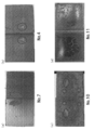
- Sample No. 7 is an image of the metal porous plate portion in FIG. 2 (a) to 2 (d) show photographs of the bonded surfaces after drying of 4, 7, 10, and 11.
- Sample No. 2 shown in FIG. 7 part of the slurry adheres to the base material side when the joint surface is peeled off, but the Ti powder is densely present over the entire surface, and the surface of the metal porous plate and the base material is visible. Absent. Sample No. 2 shown in FIG. In No.
- Example 2 Sample No. of Example 1 above. No. 7 was subjected to a tensile test according to ASTM (American Society for Testing and Materials) F-1147. For comparison, Sample No. 1 was used except that a plate-like member having an opening a was not provided. In the same manner as in Sample 7, 12 (that is, the metal porous plate of sample No. 12 is composed only of a porous body in which the area ratio of the apertures in the plane perpendicular to the thickness direction is 65% in any plane. Was 1.5 mm) and a tensile test was performed.
- ASTM American Society for Testing and Materials
- the bonding force between the metal porous plate and the base material was determined as Sample No. 7 is 60 MPa, sample no. 12 was 35 MPa.
- Sample No. 2 in which the area ratio of the opening a on the side facing the substrate is smaller than the area ratio of the opening b on the side facing the living body side.
- FDA Food Drug Administration
- the area ratio of the opening on the side facing the sample and the area ratio of the opening on the side facing the living body are the same. Compared to 12, it was possible to secure a sufficient bonding area between the metal porous plate and the base material, and to have a sufficient bonding strength with no problems in clinical use.
- the metal porous plate for living body of the present invention is suitably used as a surface modifying member for implant materials such as artificial bones, artificial joints, and artificial tooth roots.
Landscapes
- Health & Medical Sciences (AREA)
- Chemical & Material Sciences (AREA)
- Engineering & Computer Science (AREA)
- Veterinary Medicine (AREA)
- Public Health (AREA)
- General Health & Medical Sciences (AREA)
- Animal Behavior & Ethology (AREA)
- Life Sciences & Earth Sciences (AREA)
- Mechanical Engineering (AREA)
- Epidemiology (AREA)
- Transplantation (AREA)
- Materials Engineering (AREA)
- Oral & Maxillofacial Surgery (AREA)
- Vascular Medicine (AREA)
- Heart & Thoracic Surgery (AREA)
- Manufacturing & Machinery (AREA)
- Dermatology (AREA)
- Medicinal Chemistry (AREA)
- Surgery (AREA)
- Inorganic Chemistry (AREA)
- Dispersion Chemistry (AREA)
- Metallurgy (AREA)
- Organic Chemistry (AREA)
- Biomedical Technology (AREA)
- Physics & Mathematics (AREA)
- Plasma & Fusion (AREA)
- Cardiology (AREA)
- Orthopedic Medicine & Surgery (AREA)
- Composite Materials (AREA)
- Materials For Medical Uses (AREA)
- Prostheses (AREA)
- Dental Preparations (AREA)
Abstract
Description
純Tiの粉末を、アトマイズ法により調製した(平均粒径は、30μm)。デジタル化された三次元画像データに従って、前記粉末にレーザーを照射して、金属製多孔質板を作製した。該金属製多孔質板は、詳細には、表1に示す条件(開孔径、面積割合、開孔間距離)を満たし、厚み方向に貫通した開孔aを有する0.3mmの板状部材(50mm×50mm×厚み0.3mm)と、その上に形成される多孔体であって、厚み方向に垂直な面における開孔の面積率がいずれの面においても65%である厚さ1.2mmの多孔体(すなわち、生体に対面する側の表面に存在する開孔の面積率も65%)とから構成される。なお該多孔体部分の空隙率は65%である。積層造形の条件は、レーザービームの照射径が100μm、積層厚さが30μmであった。
上記した試料の作製工程における乾燥工程後に、金属製多孔質板の表面(生体側)へのスラリーの漏れを目視で観察し、以下の基準で評価した。◎、○及び△を合格とした。
◎:漏れが観察されない。
○:漏れが観察されるが、ごく一部である。
△:漏れが部分的に(数箇所)観察される。
×:漏れが略全面に観察される。
(2)乾燥後の接合面の観察
上記した試料の作製工程における乾燥工程後に、Ti合金板(基材)と金属製多孔質板とを分離して接合面を目視で観察し、以下の基準で評価した。◎、○及び△を合格とした。
◎:基材と多孔質板の接合面全体にわたってTi粉末が密に存在し、基材又は多孔体の表面は見えない。
○:基材と多孔質板の接合面において、Ti粉末が粗である箇所や、Ti粉末の存在していない箇所がごく一部存在する。
△:基材と多孔質板の接合面において、Ti粉末が粗である箇所や、Ti粉末の存在していない箇所が数箇所存在する。
×:基材と多孔質板の接合面において、Ti粉末の存在していない箇所が広い範囲で存在する。

上記実施例1の試料No.7について、ASTM(American Society for Testing and Materials) F-1147に従って、引張試験を行った。また、比較のため、開孔aを有する板状部材を設けなかったこと以外は、試料No.7と同様にして試料No.12を作製し(すなわち、試料No.12の金属製多孔質板は、厚み方向に垂直な面における開孔の面積率がいずれの面においても65%である多孔体のみから構成される。厚みは1.5mm)、引張試験を行った。
Claims (6)
- 生体内インプラント材料の表面に接合される金属製多孔質板であって、
前記インプラント材料に対面する側の表面に存在する開孔aの面積率Aが、生体に対面する側の表面に存在する開孔bの面積率Bよりも小さく、
前記開孔aは、生体側に連通していることを特徴とする生体用金属製多孔質板。 - 積層造形で製造されている請求項1に記載の生体用金属製多孔質板。
- 前記インプラント材料に対面する側の表面における開孔aの面積率が0.4~30%であり、該表面において隣り合う開孔a同士の距離が0.5~7.0mmであり、前記開孔aの孔径は600μmを超えない請求項1又は2に記載の生体用金属製多孔質板。
- 前記開孔aの厚みは0.5mmを超えない請求項1~3のいずれかに記載の生体用金属製多孔質板。
- 表面の少なくとも一部に、請求項1~4のいずれかに記載の生体用金属製多孔質板が接合されていることを特徴とする生体内インプラント材料。
- 前記生体用金属製多孔質板が、金属粉を含有するスラリーを用いて接合される請求項5に記載の生体内インプラント材料。
Priority Applications (2)
| Application Number | Priority Date | Filing Date | Title |
|---|---|---|---|
| EP12850802.5A EP2783705A4 (en) | 2011-11-24 | 2012-08-20 | BIOMEDICAL POROUS METAL PLATE |
| US14/359,758 US20140335370A1 (en) | 2011-11-24 | 2012-08-20 | Biocompatible metallic porous plate |
Applications Claiming Priority (2)
| Application Number | Priority Date | Filing Date | Title |
|---|---|---|---|
| JP2011256673 | 2011-11-24 | ||
| JP2011-256673 | 2011-11-24 |
Publications (1)
| Publication Number | Publication Date |
|---|---|
| WO2013077046A1 true WO2013077046A1 (ja) | 2013-05-30 |
Family
ID=48469506
Family Applications (1)
| Application Number | Title | Priority Date | Filing Date |
|---|---|---|---|
| PCT/JP2012/070993 Ceased WO2013077046A1 (ja) | 2011-11-24 | 2012-08-20 | 生体用金属製多孔質板 |
Country Status (4)
| Country | Link |
|---|---|
| US (1) | US20140335370A1 (ja) |
| EP (1) | EP2783705A4 (ja) |
| JP (1) | JPWO2013077046A1 (ja) |
| WO (1) | WO2013077046A1 (ja) |
Families Citing this family (1)
| Publication number | Priority date | Publication date | Assignee | Title |
|---|---|---|---|---|
| AU2021214324A1 (en) * | 2020-01-31 | 2022-08-18 | Kyocera Corporation | Bioimplant and method for manufacturing bioimplant |
Citations (9)
| Publication number | Priority date | Publication date | Assignee | Title |
|---|---|---|---|---|
| JPH01265955A (ja) * | 1988-04-15 | 1989-10-24 | Kobe Steel Ltd | 生体骨親和部材および該部材を接合した代替骨 |
| US4976738A (en) * | 1985-01-09 | 1990-12-11 | Sulzer Brothers Limited | Porous metal overlay for an implant surface |
| JPH04141163A (ja) * | 1990-10-01 | 1992-05-14 | Kawasaki Steel Corp | 骨親和性に優れた金属多孔質材料およびその製造方法 |
| JPH067388A (ja) * | 1992-04-17 | 1994-01-18 | Kyocera Corp | 人工補綴部材とその製造方法 |
| JPH0987707A (ja) * | 1995-09-27 | 1997-03-31 | Mitsubishi Materials Corp | 多孔質焼結金属接合体の製造方法 |
| JP2006528515A (ja) * | 2003-07-24 | 2006-12-21 | テコメット・インコーポレーテッド | 海綿状の構造体 |
| JP2007151805A (ja) | 2005-12-05 | 2007-06-21 | Mitsubishi Materials Corp | 医療用デバイスおよび医療用デバイスの表面改質方法 |
| JP2011256673A (ja) | 2010-06-11 | 2011-12-22 | Kumagai Gumi Co Ltd | 床構造 |
| JP2012100847A (ja) * | 2010-11-10 | 2012-05-31 | Mitsubishi Materials Corp | 多孔質インプラント素材 |
Family Cites Families (6)
| Publication number | Priority date | Publication date | Assignee | Title |
|---|---|---|---|---|
| CH645265A5 (de) * | 1980-04-29 | 1984-09-28 | Sulzer Ag | Verankerungselement eines knochenimplantates. |
| US5387243A (en) * | 1992-11-23 | 1995-02-07 | Zimmer, Inc. | Method for converting a cementable implant to a press fit implant |
| JPH1147171A (ja) * | 1997-07-31 | 1999-02-23 | Kyocera Corp | 人工補綴部材 |
| US6610096B2 (en) * | 2001-08-22 | 2003-08-26 | Macdonald Stuart G. | Prosthetic implants having enhanced utility |
| US6945448B2 (en) * | 2002-06-18 | 2005-09-20 | Zimmer Technology, Inc. | Method for attaching a porous metal layer to a metal substrate |
| US8524265B2 (en) * | 2006-08-17 | 2013-09-03 | Warsaw Orthopedic, Inc. | Medical implant sheets useful for tissue regeneration |
-
2012
- 2012-08-20 US US14/359,758 patent/US20140335370A1/en not_active Abandoned
- 2012-08-20 WO PCT/JP2012/070993 patent/WO2013077046A1/ja not_active Ceased
- 2012-08-20 JP JP2013545817A patent/JPWO2013077046A1/ja active Pending
- 2012-08-20 EP EP12850802.5A patent/EP2783705A4/en not_active Withdrawn
Patent Citations (9)
| Publication number | Priority date | Publication date | Assignee | Title |
|---|---|---|---|---|
| US4976738A (en) * | 1985-01-09 | 1990-12-11 | Sulzer Brothers Limited | Porous metal overlay for an implant surface |
| JPH01265955A (ja) * | 1988-04-15 | 1989-10-24 | Kobe Steel Ltd | 生体骨親和部材および該部材を接合した代替骨 |
| JPH04141163A (ja) * | 1990-10-01 | 1992-05-14 | Kawasaki Steel Corp | 骨親和性に優れた金属多孔質材料およびその製造方法 |
| JPH067388A (ja) * | 1992-04-17 | 1994-01-18 | Kyocera Corp | 人工補綴部材とその製造方法 |
| JPH0987707A (ja) * | 1995-09-27 | 1997-03-31 | Mitsubishi Materials Corp | 多孔質焼結金属接合体の製造方法 |
| JP2006528515A (ja) * | 2003-07-24 | 2006-12-21 | テコメット・インコーポレーテッド | 海綿状の構造体 |
| JP2007151805A (ja) | 2005-12-05 | 2007-06-21 | Mitsubishi Materials Corp | 医療用デバイスおよび医療用デバイスの表面改質方法 |
| JP2011256673A (ja) | 2010-06-11 | 2011-12-22 | Kumagai Gumi Co Ltd | 床構造 |
| JP2012100847A (ja) * | 2010-11-10 | 2012-05-31 | Mitsubishi Materials Corp | 多孔質インプラント素材 |
Non-Patent Citations (1)
| Title |
|---|
| See also references of EP2783705A4 |
Also Published As
| Publication number | Publication date |
|---|---|
| JPWO2013077046A1 (ja) | 2015-04-27 |
| EP2783705A4 (en) | 2015-07-22 |
| EP2783705A1 (en) | 2014-10-01 |
| US20140335370A1 (en) | 2014-11-13 |
Similar Documents
| Publication | Publication Date | Title |
|---|---|---|
| US6945448B2 (en) | Method for attaching a porous metal layer to a metal substrate | |
| Xiong et al. | Fabrication of porous titanium implants by three-dimensional printing and sintering at different temperatures | |
| JP4339606B2 (ja) | 多孔性金属足場 | |
| JP4911566B2 (ja) | 医療用デバイスおよび医療用デバイスの表面改質方法 | |
| JP6933879B2 (ja) | 多孔質構造体、及びその作製方法 | |
| CN104411271B (zh) | 人工关节用柄、人工关节用柄的部件以及人工关节用柄的制造方法 | |
| Muth et al. | Novel highly porous metal technology in artificial hip and knee replacement: processing methodologies and clinical applications | |
| CN103074511B (zh) | 一种医用多孔植入合金材料及其制备方法 | |
| da Costa Valente et al. | Analysis of the mechanical and physicochemical properties of Ti‐6Al‐4 V discs obtained by selective laser melting and subtractive manufacturing method | |
| Faria et al. | Ti6Al4V laser surface preparation and functionalization using hydroxyapatite for biomedical applications | |
| JP2010531694A (ja) | 多孔性芯と緻密な表面層から構成された外科用インプラント | |
| JP2012130715A (ja) | インプラント用の開放孔型生体適合性表面層、その製造方法、及び使用 | |
| CN111631842B (zh) | 一种制备骨缺损假体的方法 | |
| CN105919698A (zh) | 假体部件及其制造方法 | |
| CN112057674A (zh) | 一种表面具有微纳结构的诱骨医用钛合金及其制备方法 | |
| JPWO2013077046A1 (ja) | 生体用金属製多孔質板 | |
| JP6464470B2 (ja) | インプラント及びその製造方法 | |
| JPH0349766A (ja) | 骨親和性に優れた多孔質体の製造方法 | |
| KR100858105B1 (ko) | 다양한 형상을 갖는 다공성 치과용 임플란트 픽스쳐 및 그제조방법 | |
| CN110614372B (zh) | 具有曲面的层叠成型多孔部件的一步制造方法 | |
| CN110614369A (zh) | 层压成型的多孔部件的一步制造方法 | |
| CN205849592U (zh) | 髋关节假体部件 | |
| TW201320971A (zh) | 植牙牙根及其表面之成型方法 | |
| JPH0739578A (ja) | 金属製生体埋込材およびその製造方法 | |
| Sun et al. | Characteristics and chemical stability of the bioactive titania layer formed on Ti, Ti-6Al-4V and NiTi SMA through a low temperature oxidation process |
Legal Events
| Date | Code | Title | Description |
|---|---|---|---|
| 121 | Ep: the epo has been informed by wipo that ep was designated in this application |
Ref document number: 12850802 Country of ref document: EP Kind code of ref document: A1 |
|
| ENP | Entry into the national phase |
Ref document number: 2013545817 Country of ref document: JP Kind code of ref document: A |
|
| NENP | Non-entry into the national phase |
Ref country code: DE |
|
| REEP | Request for entry into the european phase |
Ref document number: 2012850802 Country of ref document: EP |
|
| WWE | Wipo information: entry into national phase |
Ref document number: 2012850802 Country of ref document: EP |
|
| WWE | Wipo information: entry into national phase |
Ref document number: 14359758 Country of ref document: US |