WO2013077241A1 - 電動パワーステアリング装置 - Google Patents
電動パワーステアリング装置 Download PDFInfo
- Publication number
- WO2013077241A1 WO2013077241A1 PCT/JP2012/079610 JP2012079610W WO2013077241A1 WO 2013077241 A1 WO2013077241 A1 WO 2013077241A1 JP 2012079610 W JP2012079610 W JP 2012079610W WO 2013077241 A1 WO2013077241 A1 WO 2013077241A1
- Authority
- WO
- WIPO (PCT)
- Prior art keywords
- current detection
- detection circuit
- motor current
- control
- power steering
- Prior art date
- Legal status (The legal status is an assumption and is not a legal conclusion. Google has not performed a legal analysis and makes no representation as to the accuracy of the status listed.)
- Ceased
Links
Images


Classifications
-
- G—PHYSICS
- G01—MEASURING; TESTING
- G01R—MEASURING ELECTRIC VARIABLES; MEASURING MAGNETIC VARIABLES
- G01R31/00—Arrangements for testing electric properties; Arrangements for locating electric faults; Arrangements for electrical testing characterised by what is being tested not provided for elsewhere
- G01R31/34—Testing dynamo-electric machines
- G01R31/343—Testing dynamo-electric machines in operation
-
- B—PERFORMING OPERATIONS; TRANSPORTING
- B62—LAND VEHICLES FOR TRAVELLING OTHERWISE THAN ON RAILS
- B62D—MOTOR VEHICLES; TRAILERS
- B62D5/00—Power-assisted or power-driven steering
- B62D5/04—Power-assisted or power-driven steering electrical, e.g. using an electric servo-motor connected to, or forming part of, the steering gear
- B62D5/0457—Power-assisted or power-driven steering electrical, e.g. using an electric servo-motor connected to, or forming part of, the steering gear characterised by control features of the drive means as such
- B62D5/0481—Power-assisted or power-driven steering electrical, e.g. using an electric servo-motor connected to, or forming part of, the steering gear characterised by control features of the drive means as such monitoring the steering system, e.g. failures
- B62D5/049—Power-assisted or power-driven steering electrical, e.g. using an electric servo-motor connected to, or forming part of, the steering gear characterised by control features of the drive means as such monitoring the steering system, e.g. failures detecting sensor failures
-
- H—ELECTRICITY
- H02—GENERATION; CONVERSION OR DISTRIBUTION OF ELECTRIC POWER
- H02P—CONTROL OR REGULATION OF ELECTRIC MOTORS, ELECTRIC GENERATORS OR DYNAMO-ELECTRIC CONVERTERS; CONTROLLING TRANSFORMERS, REACTORS OR CHOKE COILS
- H02P23/00—Arrangements or methods for the control of AC motors characterised by a control method other than vector control
-
- H—ELECTRICITY
- H02—GENERATION; CONVERSION OR DISTRIBUTION OF ELECTRIC POWER
- H02M—APPARATUS FOR CONVERSION BETWEEN AC AND AC, BETWEEN AC AND DC, OR BETWEEN DC AND DC, AND FOR USE WITH MAINS OR SIMILAR POWER SUPPLY SYSTEMS; CONVERSION OF DC OR AC INPUT POWER INTO SURGE OUTPUT POWER; CONTROL OR REGULATION THEREOF
- H02M1/00—Details of apparatus for conversion
- H02M1/0003—Details of control, feedback or regulation circuits
- H02M1/0009—Devices or circuits for detecting current in a converter
-
- H—ELECTRICITY
- H02—GENERATION; CONVERSION OR DISTRIBUTION OF ELECTRIC POWER
- H02M—APPARATUS FOR CONVERSION BETWEEN AC AND AC, BETWEEN AC AND DC, OR BETWEEN DC AND DC, AND FOR USE WITH MAINS OR SIMILAR POWER SUPPLY SYSTEMS; CONVERSION OF DC OR AC INPUT POWER INTO SURGE OUTPUT POWER; CONTROL OR REGULATION THEREOF
- H02M7/00—Conversion of AC power input into DC power output; Conversion of DC power input into AC power output
- H02M7/42—Conversion of DC power input into AC power output without possibility of reversal
- H02M7/44—Conversion of DC power input into AC power output without possibility of reversal by static converters
- H02M7/48—Conversion of DC power input into AC power output without possibility of reversal by static converters using discharge tubes with control electrode or semiconductor devices with control electrode
- H02M7/53—Conversion of DC power input into AC power output without possibility of reversal by static converters using discharge tubes with control electrode or semiconductor devices with control electrode using devices of a triode or transistor type requiring continuous application of a control signal
- H02M7/537—Conversion of DC power input into AC power output without possibility of reversal by static converters using discharge tubes with control electrode or semiconductor devices with control electrode using devices of a triode or transistor type requiring continuous application of a control signal using semiconductor devices only, e.g. single switched pulse inverters
- H02M7/539—Conversion of DC power input into AC power output without possibility of reversal by static converters using discharge tubes with control electrode or semiconductor devices with control electrode using devices of a triode or transistor type requiring continuous application of a control signal using semiconductor devices only, e.g. single switched pulse inverters with automatic control of output wave form or frequency
- H02M7/5395—Conversion of DC power input into AC power output without possibility of reversal by static converters using discharge tubes with control electrode or semiconductor devices with control electrode using devices of a triode or transistor type requiring continuous application of a control signal using semiconductor devices only, e.g. single switched pulse inverters with automatic control of output wave form or frequency by pulse-width modulation
Definitions
- the present invention relates to an electric power steering apparatus in which a steering assist force is applied to a steering system of a vehicle by a multiphase motor that is driven and controlled by a PWM duty command value, and more particularly, a drive unit and a power source (battery) for PWM driving.
- a single current detection circuit (1-shunt-type current detection circuit) is provided between the two and the assist control is performed, and a high-function electric power steering system that improves safety by diagnosing a failure or abnormality of the current detection circuit or the like Relates to the device.
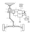
- An electric power steering apparatus that assists and controls a vehicle steering system with the rotational force of a motor urges an assisting force on a steering shaft or a rack shaft by a transmission mechanism such as a gear or a belt via a reduction gear. It is like that.
- An inverter is used in the motor drive circuit in order to supply a current to the motor so that the motor generates a desired torque.
- the column shaft 2 is provided with a torque sensor 10 that detects the steering torque of the handle 1, and a motor 20 that assists the steering force of the handle 1 is connected to the column shaft 2 via the reduction gear 3. .
- the control unit (ECU) 100 that controls the electric power steering apparatus is supplied with electric power from the battery 13 and also receives an ignition key signal via the ignition key 11.
- the control unit 100 calculates a current command value of an assist (steering assistance) command based on the steering torque T detected by the torque sensor 10 and the vehicle speed Vs detected by the vehicle speed sensor 12, and the current control unit calculates the current command.
- the current I supplied to the motor 20 is controlled by a voltage command value E in which the value is compensated.
- the vehicle speed Vs is a CAN (Controller Area Network) or the like.
- the control unit 100 is mainly composed of a CPU (including MPU and MCU), and FIG. 2 shows general functions executed by a program inside the CPU.
- the function and operation of the control unit 100 will be described with reference to FIG. 2.
- the steering torque T detected by the torque sensor 10 and the vehicle speed Vs detected by the vehicle speed sensor 12 are calculated as a current command value that calculates a current command value Iref1.
- the current command value calculation unit 101 determines, for example, a current command value Iref1, which is a control target value of current supplied to the three-phase motor 20, using an assist map or the like based on the input steering torque T and vehicle speed Vs. .
- the current command value Iref1 is input to the current limiter 103 as the current command value Iref2 through the adder 102A, and the current command value Iref3 with the maximum current limited is input to the subtractor 102B and fed back to the motor current value Im fed back.
- the voltage command value E whose characteristics have been improved by the current control unit 104 is input to the PWM control unit 105, and the motor 20 is PWM driven via an inverter 106 as a drive unit.
- the current value Im of the motor 20 is detected by the current detection circuit 120 in the inverter 106 and fed back to the subtraction unit 102B.
- the inverter 106 generally uses an FET as a switching element, and is configured by an FET bridge circuit.
- the compensation signal CM is added from the compensation unit 110 to the addition unit 102A, and the system system is compensated by the addition of the compensation signal CM so as to improve the convergence and inertia characteristics.
- the compensation unit 110 adds the self-aligning torque (SAT) 113 and the inertia 112 by the addition unit 114, further adds the convergence 111 to the addition result by the addition unit 115, and adds the addition result of the addition unit 115 to the compensation signal CM. It is said.
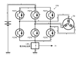
- the PWM control unit 105 drives the respective gates of the FET1 to FET6 with the duty calculation unit 105A that calculates the PWM duty command values D1 to D6 for three phases according to a predetermined formula for the voltage command value E, and the PWM duty command values D1 to D6.
- the inverter 106 includes an upper and lower arm made up of a U-phase upper stage FET1 and a lower stage FET4, an upper and lower arm made up of a V-phase upper stage FET2 and a lower stage FET5, and W
- the motor 20 is driven by being turned on / off by PWM duty command values D1 to D6.
- the three-phase bridge is composed of upper and lower arms composed of upper and lower FETs 3 and 6.
- the current detection circuit 120 There is unification (one shunt type current detection circuit).
- a single shunt type current detection circuit is known as a unitary current detection circuit, and the configuration of a single shunt type current detection circuit 120 is as shown in FIG. 4, for example (Japanese Patent Laid-Open No. 2009-131064). .
- one shunt resistor R1 is connected between the bottom arm of the FET bridge and the ground (GND), and a voltage drop caused by the shunt resistor R1 when a current flows through the FET bridge is an operational amplifier (differential amplifier circuit).
- 121 and resistors R2 to R4 are converted into a current value Ima, and further A / D converted at a predetermined timing by an A / D converter 122 through a filter composed of a resistor R6 and a capacitor C1, and a digital current value Im is obtained. It is designed to output.
- 2.5V which becomes a reference voltage is connected to the positive terminal input of the operational amplifier 121 through the resistor R5.
- FIG. 5 shows a connection diagram of the power source (battery), the inverter 106, the current detection circuit 120, and the motor 20, and the U-phase upper FET 1 is ON (the lower FET 4 is OFF), and the V-phase upper FET 2 is OFF (the lower FET 5 is ON), a current path (broken line) when the upper stage FET 3 of the W phase is OFF (the lower stage FET 6 is ON) is shown. Further, FIG. 6 shows a state where the upper FET 1 of the U phase is ON (lower FET 4 is OFF), the upper FET 2 of the V phase is ON (lower FET 5 is OFF), and the upper FET 3 of the W phase is OFF (lower FET 6 is ON).
- JP 2009-131064 A Japanese Unexamined Patent Publication No. 2009-232569
- the present invention has been made under the circumstances described above, and an object of the present invention is to detect each phase current of a motor with a single shunt type current detection circuit and to easily diagnose a failure or abnormality of the current detection circuit.
- An object of the present invention is to provide an electric power steering apparatus that is reliably performed with a configuration and further improved in safety.
- the present invention calculates a current command value based on a steering torque and a vehicle speed, drives a multiphase motor via an inverter constituted by an FET bridge based on the current command value, and controls a steering system by driving control of the motor.
- the object of the present invention is to provide one shunt resistor connected to the inverter and to both ends of the shunt resistor in the positive direction, and detect the phase current of the motor to detect the motor
- a control motor current detection circuit for detecting a control motor current detection value for assist control, and a diagnostic motor current detection for detecting a failure of the control motor current detection circuit connected in opposite directions to both ends of the shunt resistor A circuit, This is achieved by detecting each phase current of the motor by a single shunt type and performing the assist control, and by using two systems for amplifying the voltage across the shunt resistor.
- the object of the present invention is to compare the control motor current detection value detected by the control motor current detection circuit with the diagnosis motor current detection value detected by the diagnosis motor current detection circuit.
- the maximum current detection circuit is configured to hold a peak of the diagnostic motor current detection voltage output from the diagnostic motor current detection circuit for a certain period of time, or the maximum current detection circuit
- the diagnosis motor current detection circuit comprising a peak hold transistor, a resistor and a capacitor for generating a charge / discharge time constant.
- An output is input to the base of the transistor, and a maximum current detection value detected by the maximum current detection circuit is detected by inserting a charging resistor between the emitter of the transistor and the resistor and capacitor, and the control
- the control motor current detection value detected by the motor current detection circuit for use with the diagnosis motor current detection value detected by the diagnosis motor current detection circuit, the control motor current detection circuit,
- the diagnosis motor current detection circuit and the maximum current detection circuit are diagnosed for failure or abnormality, or the diagnosis motor current detection circuit outputs the output voltage of the diagnosis motor current detection circuit.
- the control motor current detection circuit is configured such that the output voltage of the control motor current detection circuit is zero when the current flowing through the shunt resistor is zero.
- the control current detected by the control motor current detection circuit is reduced according to the magnitude of the current, or the control current detected by the control motor current detection circuit
- the sum of the motor current detection voltage and the diagnosis motor current detection voltage detected by the diagnosis motor current detection circuit is a constant voltage regardless of the current when it is normal.
- the diagnostic motor current detection circuit is configured by an operational amplifier (differential amplifier circuit), and the maximum current detection circuit is It consists of a peak hold transistor, a resistor that generates a charge / discharge time constant, and a capacitor.
- the output of the operational amplifier of the diagnostic motor current detection circuit is input to the base of the transistor, and the charge / discharge capacitor is connected to the emitter of the transistor via the charge resistor.
- the control motor current detection value detected by the control motor current detection circuit is compared with the diagnosis motor current detection value detected by the diagnosis motor current detection circuit. It is possible to detect whether the motor current detection circuit is faulty.
- a maximum current detection circuit that holds the peak of the diagnosis motor current detection voltage output from the diagnosis motor current detection circuit for a certain period of time is connected after the diagnosis motor current detection circuit, so the maximum current detection value is monitored. By doing so, for example, an overcurrent failure such as an FET short-circuit failure in the inverter can be detected.
- a comparison is made between the maximum current detection value detected by the maximum current detection circuit, the control motor current detection value, and the diagnosis motor current detection value, so that one of the circuits has failed. Since it can be detected, it is also possible to continue the assist control by determining the failure location.
- the present invention is a current detection circuit in which one shunt resistor is connected between an inverter and ground (GND), and a motor current is detected from a voltage across the shunt resistor.
- a circuit for amplifying the voltage across the shunt resistor is a motor It consists of two circuits, a control motor current detection circuit used for control and a diagnosis motor current detection circuit for detecting faults (including abnormalities) in the control motor current detection circuit. A failure of the control motor current detection circuit is detected by comparing the detected control motor current detection value with the diagnosis motor current detection value detected by the diagnosis motor current detection circuit.
- the diagnostic motor current detection circuit is configured such that when the output voltage of the diagnostic motor current detection circuit flows from the power supply side to the ground (GND) side with reference to the voltage when the current flowing through the shunt resistor is zero,
- the maximum current that is configured to increase according to the magnitude of the current and that holds the peak of the diagnostic motor current detection voltage output from the diagnostic motor current detection circuit for a certain period of time after the diagnostic motor current detection circuit
- control motor current detection circuit is configured such that when the output voltage of the control motor current detection circuit flows from the power supply side to the ground side with reference to the voltage when the current flowing through the shunt resistor is 0, the current
- the sum of the control motor current detection voltage detected by the control motor current detection circuit and the diagnosis motor current detection voltage detected by the diagnosis motor current detection circuit is as follows: It is configured to be a constant voltage regardless of the current at normal time, and the motor current detection voltage sum that is the sum of the control motor current detection voltage and the diagnosis motor current detection voltage is monitored. Abnormalities such as failure to output normal voltage due to failure of diagnostic motor current detection voltage are detected.
- the safety of the electric power steering apparatus can be further enhanced.
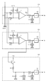
- FIG. 7 shows a configuration example of the present invention corresponding to FIG. 4, and the current detection circuit 120 in FIG. 4 functions as a control motor current detection circuit in the present invention, and a control circuit is provided at both ends of the shunt resistor R1.
- a motor current detection circuit 120 is connected, a diagnosis motor current detection circuit 130 is further connected to both ends of the shunt resistor R1, and a maximum current detection circuit 140 is connected to the subsequent stage of the diagnosis motor current detection circuit 130.
- the control motor current detection circuit 120 is composed of an operational amplifier (differential amplifier circuit) 121, and its output voltage is 2.5 V when the current flowing through the shunt resistor R1 is 0, and the current is from the power supply side to the ground side. Assuming that the positive current flows when the positive current flows, the voltage drops from 2.5 V depending on the magnitude of the positive current. For example, when 100 A flows in the positive direction, the output voltage decreases by 2 V with respect to the 2.5 V voltage to 0.5 V, and when 100 A flows in the negative direction, the output voltage decreases by 2 V with respect to 2.5 V and decreases to 0.5 V. It becomes.
- the control motor current detection voltage detected by the control motor current detection circuit 120 is converted into a physical value Im after A / D conversion by the A / D conversion unit 122 by a CPU (including MCU and the like) at an arbitrary timing. Used to control motor current.
- the diagnostic motor current detection circuit 130 is composed of an operational amplifier (differential amplifier circuit) 131, and its output voltage (output of the operational amplifier 131) is 2.5 V when the current flowing through the shunt resistor R1 is 0, Assuming that the positive current is when the current flows from the power supply side to the ground side, when the positive current flows, the voltage rises from 2.5 V depending on the magnitude of the current. For example, when 100A flows in the positive direction, the output voltage decreases by 2V to 2.5V with respect to the 2.5V voltage, and when 100A flows in the negative direction, the output voltage increases by 2V to 2.5V and increases to 1.0V It becomes.
- the diagnostic motor current detection voltage detected by the diagnostic motor current detection circuit 130 is converted into a physical value (Is) after A / D conversion by the A / D conversion unit 132 by the CPU (including MCU) at an arbitrary timing. And used to detect an abnormality in the detected value of the control motor current.
- the upper voltage of the shunt resistor R1 is input to the negative input terminal of the operational amplifier 121 of the control motor current detection circuit 120 via the input resistance R2 (positive direction), and the operational amplifier 131 of the diagnostic motor current detection circuit 130 is supplied.
- the lower voltage of the shunt resistor R1 is input to the negative input terminal via the input resistor R11 (reverse direction).
- the maximum current detection circuit 140 includes a transistor Q1, a charge / discharge capacitor C21, a charge resistor R31, and a discharge resistor R32.
- the maximum current detection circuit 140 is based on the output voltage of the diagnostic motor current detection circuit 130 (output of the operational amplifier 131).
- the voltage of the charging / discharging capacitor C21 is smaller than the voltage at which the emitter voltage Vbe has decreased (during charging)
- the voltage at which the base emitter voltage Vbe of the transistor Q1 has decreased with respect to the output voltage of the diagnostic motor current detection circuit 130
- the charge / discharge capacitor C21 is charged according to the time constants of the charge resistor R31 and the charge / discharge capacitor C21.
- the discharging resistor R32 and the charging / discharging capacitor When the voltage of the charging / discharging capacitor C21 is larger than the voltage at which the base-emitter voltage Vbe of the transistor Q1 is lowered (during discharging) with respect to the output voltage of the diagnostic motor current detection circuit 130, the discharging resistor R32 and the charging / discharging capacitor The charge is discharged from the charge / discharge capacitor C21 according to the time constant of C21.
- the resistor R33 and the capacitor C22 constitute a filter, and the output from which noise is removed is A / D converted by the A / D converter 141 and output as a digital value Ix.
- the maximum current detection circuit 140 is configured to peak-hold the output voltage of the diagnostic motor current detection circuit 130 by the discharge resistor R32 and the charge / discharge capacitor C21. This is a circuit that peaks and holds the positive current when the current flowing through the shunt resistor R1 flows from the power supply side to the ground side of the inverter. Therefore, not only the overcurrent due to the arm short circuit of the inverter but also the short-circuit failure of the lower FET, for example The peak of the overcurrent that occurs when the upper FET is PWM-driven at 20 KHz (50 ⁇ s or less) and intermittently (20 KHz cycle) is held for a certain period of time.
- the peak-held voltage is converted into a physical value (Ix) after A / D conversion by the A / D conversion unit 141 by the CPU at an arbitrary timing, and the maximum current abnormality diagnosis, the control motor current detection circuit 120 and the diagnosis are performed. This is used for fault diagnosis of the motor current detection circuit 130.
- the charge / discharge time constant generated by the resistor R32 and the capacitor C21 is preferably on the order of ⁇ s, and the discharge time constant is preferably 200 ⁇ s to 1 ms that can hold the peak value reliably for 50 ⁇ s.
- control motor current detection value Im is input (step S1), and then the diagnosis motor current detection value Is is input (step S2). This order of input may be reversed.
- the control motor current detection value Im and the diagnosis motor current detection value Is indicate the same current detection value if normal, but the offset voltage of the control motor current detection circuit 120 or the diagnosis motor current detection circuit 130 changes. When such a failure or a failure (including an abnormality) in which the gain changes occurs, a difference occurs between the control motor current detection value Im and the diagnosis motor current detection value Is.
- step S3 the difference between the control motor current detection value Im and the diagnosis motor current detection value Is is calculated (step S3), and it is determined whether or not the difference is a predetermined value, for example, ⁇ 10A or more (step S4). If the difference is ⁇ 10 A or more, it is determined that there is an abnormality (including a failure) (step S10).
- step S11 If it is determined that there is an abnormality, the power supply to the inverter is stopped (step S11), and the assist control is stopped (step S12).
- step S4 if it is determined in step S4 that the difference is smaller than ⁇ 10 A, the maximum current detection value Ix detected by the maximum current detection circuit 140 is further input and monitored (step S5), and the maximum current detection is performed. It is determined whether or not the value Ix is a predetermined value, for example, 150A or more (step S6). When the maximum current detection value Ix is 150 A or more, it is determined that an inverter overcurrent failure (for example, FET short-circuit) has occurred, and an abnormality (including failure) is detected (step S10). Is stopped (step S11), and the assist is stopped (step S12).
- an inverter overcurrent failure for example, FET short-circuit
- the maximum current detection value Ix is smaller than 150 A
- the following diagnosis is further performed. That is, the maximum current detection value Ix, the control motor current detection value Im, and the diagnostic motor current detection value Is are correlated with each other by detecting the current flowing through the shunt resistor R1, and thus the respective current detection values are compared. By doing so, it is possible to diagnose which current detection circuit has failed. Specifically, the following comparison determinations (a) to (c) are performed. If there is a difference of a certain value or more, it is determined to be abnormal, and otherwise it is determined to be normal.
- step S20 Comparison between the maximum current detection value Ix and the control motor current detection value Im, that is, the difference between the maximum current detection value Ix and the control motor current detection value Im is calculated (step S20), and the difference is equal to or greater than the predetermined value ⁇ . It is determined whether or not (step S21).
- step S22 A comparison between the control motor current detection value Im and the diagnosis motor current detection value Is, that is, the difference between the control motor current detection value Im and the diagnosis motor current detection value Is is calculated (step S22). It is determined whether or not it is equal to or greater than a predetermined value ⁇ (step S23).
- step S24 Comparison between the diagnostic motor current detection value Is and the maximum current detection value Ix, that is, the difference between the diagnostic motor current detection value Is and the maximum current detection value Ix is calculated (step S24), and the difference is equal to or greater than a predetermined value ⁇ . It is determined whether or not (step S25). In the above determinations (a) to (c), if all the differences are smaller than the respective predetermined values, all are determined to be normal (step S26).
- an abnormal site is determined (step S30). That is, when the determination (a) is abnormal, the determination (b) is abnormal, and the determination (c) is normal, the control motor current detection value Im is determined to be abnormal. If the determination (a) is normal, the determination (b) is abnormal, and the determination (c) is abnormal, the diagnostic motor current detection value Is is determined to be abnormal, the determination (a) is abnormal, and the determination (b) Is normal and the determination (c) is abnormal, the maximum current detection value Ix is determined to be abnormal.
- the maximum current detection circuit 140 Since the maximum current detection circuit 140 is connected to the subsequent stage of the diagnostic motor current detection circuit 130, if the diagnostic motor current detection circuit 130 fails, the maximum current detection value Ix may also be an abnormal output. In that case, determination (a) is abnormal, determination (b) is abnormal, and determination (c) is abnormal.
- step S32 when it is determined that only the control motor current detection value Im is abnormal ((a) abnormal, (b) abnormal, (c) normal), control is performed for motor current control. Without using the motor current detection value Im, the current control is continued in the open loop as the backup control (step S32), and the assist is continued (step S33). In other cases, there is a possibility that the maximum current detection circuit 140 may be abnormal and it is highly possible that a failure of the inverter cannot be detected. Therefore, the process returns to step S10 to stop current control (step S11), and assists. Is stopped (step S12).
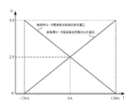
- the sum of the output voltage of the control motor current detection circuit 120 and the output voltage of the diagnosis motor current detection circuit 130 is a constant value (5 V) when normal as shown in FIG. If the sum is, for example, 5.3 V or more or 4.7 V or less, it may be determined as abnormal.
- control motor current detection circuit 120 the diagnosis motor current detection circuit 130, and the maximum current detection circuit 140 are not limited to the configuration shown in FIG. 7, and may have any form having the same function and operation. .
- the three-phase motor has been described above, the present invention can be similarly applied to a two-phase motor.
- the electric power steering apparatus provided with the compensation unit has been described above, the compensation unit is not always necessary.
Landscapes
- Engineering & Computer Science (AREA)
- Chemical & Material Sciences (AREA)
- Combustion & Propulsion (AREA)
- Transportation (AREA)
- Mechanical Engineering (AREA)
- Physics & Mathematics (AREA)
- General Physics & Mathematics (AREA)
- Power Engineering (AREA)
- Power Steering Mechanism (AREA)
- Steering Control In Accordance With Driving Conditions (AREA)
- Control Of Ac Motors In General (AREA)
Abstract
【課題】1シャント式電流検出回路でモータ各相電流の検出を行うと共に、電流検出回路の故障(異常)を簡易な構成で確実に行い、安全性を高めた電動パワーステアリング装置を提供する。 【解決手段】インバータに接続された1つのシャント抵抗と、シャント抵抗の両端に正方向に接続され、モータの相電流を検出してアシスト制御の制御用モータ電流検出値とする制御用モータ電流検出回路と、シャント抵抗の両端に逆方向に接続され、制御用モータ電流検出回路の故障を検出するための診断用モータ電流検出回路とを具備し、1シャント式でモータの各相電流を検出してアシスト制御を行うと共に、シャント抵抗の両端電圧を増幅する回路を2系統とする。
Description
本発明は、PWMのデユーティ指令値で駆動制御される多相モータにより、車両の操舵系に操舵補助力を付与するようにした電動パワーステアリング装置に関し、特にPWM駆動する駆動部と電源(バッテリ)との間に単一の電流検出回路(1シャント式電流検出回路)を設けてアシスト制御すると共に、電流検出回路等の故障や異常を診断することにより安全性を高めた高機能な電動パワーステアリング装置に関する。
車両の操舵系をモータの回転力でアシスト制御する電動パワーステアリング装置は、モータの駆動力を減速機を介してギア又はベルト等の伝達機構により、ステアリングシャフト或いはラック軸に補助力を付勢するようになっている。そして、当該モータが所望のトルクを発生するようにモータに電流を供給するため、モータ駆動回路にインバータが用いられている。
ここで、従来の電動パワーステアリング装置の一般的な構成を図1に示して説明すると、ハンドル1のコラム軸(ステアリングシャフト)2は減速ギア3、ユニバーサルジョイント4a及び4b、ピニオンラック機構5、タイロッド6a,6bを経て、更にハブユニット7a,7bを介して操向車輪8L,8Rに連結されている。また、コラム軸2には、ハンドル1の操舵トルクを検出するトルクセンサ10が設けられており、ハンドル1の操舵力を補助するモータ20が減速ギア3を介してコラム軸2に連結されている。電動パワーステアリング装置を制御するコントロールユニット(ECU)100には、バッテリ13から電力が供給されると共に、イグニションキー11を経てイグニションキー信号が入力される。コントロールユニット100は、トルクセンサ10で検出された操舵トルクTと車速センサ12で検出された車速Vsとに基づいてアシスト(操舵補助)指令の電流指令値の演算を行い、電流制御部で電流指令値に補償等を施した電圧指令値Eによってモータ20に供給する電流Iを制御する。なお、車速VsはCAN(Controller Area
Network)等から受信することも可能である。
Network)等から受信することも可能である。
コントロールユニット100は主としてCPU(MPU、MCUも含む)で構成されるが、そのCPU内部においてプログラムで実行される一般的な機能を示すと図2のようになる。
図2を参照してコントロールユニット100の機能及び動作を説明すると、トルクセンサ10で検出された操舵トルクT及び車速センサ12で検出された車速Vsは、電流指令値Iref1を演算する電流指令値演算部101に入力される。電流指令値演算部101は、入力された操舵トルクT及び車速Vsに基づいてアシストマップ等を用いて、例えば3相のモータ20に供給する電流の制御目標値である電流指令値Iref1を決定する。電流指令値Iref1は加算部102Aを経て電流指令値Iref2として電流制限部103に入力され、最大電流を制限された電流指令値Iref3が減算部102Bに入力され、フィードバックされているモータ電流値Imとの偏差Iref4(=Iref3-Im)が演算され、その偏差Iref4がPI制御等を行う電流制御部104に入力される。電流制御部104で特性改善された電圧指令値EがPWM制御部105に入力され、更に駆動部としてのインバータ106を介してモータ20がPWM駆動される。モータ20の電流値Imはインバータ106内の電流検出回路120で検出され、減算部102Bにフィードバックされる。インバータ106はスイッチング素子として一般的にFETが用いられ、FETのブリッジ回路で構成されている。
また、加算部102Aには補償部110から補償信号CMが加算されており、補償信号CMの加算によってシステム系の補償を行い、収れん性や慣性特性等を改善するようようになっている。補償部110は、セルフアライニングトルク(SAT)113と慣性112を加算部114で加算し、その加算結果に更に収れん性111を加算部115で加算し、加算部115の加算結果を補償信号CMとしている。
モータ20が3相(U,V,W)ブラシレスモータの場合、PWM制御部105及びインバータ106の詳細は例えば図3に示すような構成となっている。PWM制御部105は、電圧指令値Eを所定式に従って3相分のPWMデューティ指令値D1~D6を演算するデューティ演算部105Aと、PWMデューティ指令値D1~D6でFET1~FET6の各ゲートを駆動してON/OFFするゲート駆動部105Bとで構成されており、インバータ106は、U相の上段FET1及び下段FET4で成る上下アームと、V相の上段FET2及び下段FET5で成る上下アームと、W相の上段FET3及び下段FET6で成る上下アームとで成る3相ブリッジで構成されており、PWMデューティ指令値D1~D6でON/OFFされることによってモータ20を駆動する。
このような構成において、インバータ106の駆動電流ないしはモータ20のモータ電流を計測する必要があるが、コントロールユニット100のコンパクト化、軽量化、コストダウンの要求項目の1つとして、電流検出回路120の単一化(1シャント式電流検出回路)がある。電流検出回路の単一化として1シャント式電流検出回路が知られており、1シャント式の電流検出回路120の構成は例えば図4に示すようになっている(特開2009-131064号公報)。即ち、FETブリッジの底部アームと接地(GND)との間に1つのシャント抵抗R1が接続されており、FETブリッジに電流が流れたときのシャント抵抗R1による降下電圧を演算増幅器(差動増幅回路)121及び抵抗R2~R4で電流値Imaに換算し、更に抵抗R6及びコンデンサC1で成るフィルタを経てA/D変換部122で所定のタイミングにA/D変換し、ディジタル値の電流値Imを出力するようになっている。なお、演算増幅器121の正端子入力には、抵抗R5を経て基準電圧となる2.5Vが接続されている。
図5は電源(バッテリ)、インバータ106、電流検出回路120及びモータ20の結線図を示すと共に、U相の上段FET1がON(下段FET4はOFF)、V相の上段FET2がOFF(下段FET5はON)、W相の上段FET3がOFF(下段FET6はON)の状態時の電流経路(破線)を示している。また、図6は、U相の上段FET1がON(下段FET4はOFF)、V相の上段FET2がON(下段FET5はOFF)、W相の上段FET3がOFF(下段FET6はON)の状態時の電流経路(破線)を示している。これら図5及び図6の電流経路から分かるように、上段FETがONしている相の合計値が電流検出回路器120に検出電流として現れる。即ち、図5ではU相電流を検出することができ、図6ではU相及びV相電流を検出することができる。これは、電流検出回路120がインバータ106の上段アームと電源との間に接続されている場合も同様である。
このように従来の装置(例えば特開2009-131064号公報)では電流検出回路が設けられているものの、電流検出回路が故障(異常を含む)したときの対策が施されていないため、操舵系の安全性向上の面から故障対策の実施が強く要請されている。
また、一方では、インバータ内のFETの短絡故障による過電流故障を検出するために、電流検出回路の後段にダイオードを用いてピークホールドを行うような回路が提案されている(特開2009-232569号公報)。しかしながら、演算増幅器の出力電圧をダイオードを介して充放電用コンデンサに電荷を充電する場合、コンデンサへの充電電流が演算増幅器の負荷電流となるため、充電電流(負荷電流)が大きい場合、演算増幅器の応答性が低下してしまい、電流検出回路及びピークホールド回路の検出精度が悪化するという問題がある。
本発明は上述のような事情からなされたものであり、本発明の目的は、1シャント式電流検出回路でモータ各相電流の検出を行うと共に、電流検出回路の故障や異常の診断を簡易な構成で確実に行い、安全性を一層高めた電動パワーステアリング装置を提供することにある。
本発明は、操舵トルク及び車速に基づいて電流指令値を演算し、前記電流指令値に基づいてFETブリッジで成るインバータを介して多相のモータを駆動し、前記モータの駆動制御によって操舵系をアシスト制御する電動パワーステアリング装置に関し、本発明の上記目的は、前記インバータに接続された1つのシャント抵抗と、前記シャント抵抗の両端に正方向に接続され、前記モータの相電流を検出して前記アシスト制御の制御用モータ電流検出値とする制御用モータ電流検出回路と、前記シャント抵抗の両端に逆方向に接続され、前記制御用モータ電流検出回路の故障を検出するための診断用モータ電流検出回路とを具備し、
1シャント式で前記モータの各相電流を検出して前記アシスト制御を行うと共に、前記シャント抵抗の両端電圧を増幅する回路を2系統とすることにより達成される。
1シャント式で前記モータの各相電流を検出して前記アシスト制御を行うと共に、前記シャント抵抗の両端電圧を増幅する回路を2系統とすることにより達成される。
また、本発明の上記目的は、前記制御用モータ電流検出回路により検出された制御用モータ電流検出値と、前記診断用モータ電流検出回路により検出された診断用モータ電流検出値とを比較することにより、前記制御用モータ電流検出回路又は前記診断用モータ電流検出回路のいずれかが故障していることを検出することにより、或いは前記診断用モータ電流検出回路の後段に接続された最大電流検出回路を具備し、前記最大電流検出回路は、前記診断用モータ電流検出回路から出力される診断用モータ電流検出電圧のピークを一定時間ホールドするようになっていることにより、或いは前記最大電流検出回路を、ピークホールド用トランジスタと、充放電時定数を生成する抵抗及びコンデンサとで構成し、前記診断用モータ電流検出回路の出力を前記トランジスタのベースに入力し、前記トランジスタのエミッタと前記抵抗及びコンデンサとの間に充電抵抗を介挿することにより、或いは前記最大電流検出回路により検出された最大電流検出値と、前記制御用モータ電流検出回路により検出された制御用モータ電流検出値と、前記診断用モータ電流検出回路により検出された診断用モータ電流検出値とを比較することにより、前記制御用モータ電流検出回路、前記診断用モータ電流検出回路、前記最大電流検出回路のいずれかの故障、異常を診断するようになっていることにより、或いは前記診断用モータ電流検出回路は、前記診断用モータ電流検出回路の出力電圧が、前記シャント抵抗を流れる電流が0のときの電圧を基準として、電流が電源側から接地側に流れるときに、前記電流の大きさに応じて上昇するようになっていることにより、或いは前記制御用モータ電流検出回路は、前記制御用モータ電流検出回路の出力電圧が、前記シャント抵抗を流れる電流が0のときの電圧を基準として、電流が電源側から接地側に流れるときに、前記電流の大きさに応じて低下するようになっていることにより、或いは前記制御用モータ電流検出回路により検出された制御用モータ電流検出電圧と、前記診断用モータ電流検出回路で検出された診断用モータ電流検出電圧との和が、正常時には前記電流に関係なく一定電圧となっていることにより、より効果的に達成される。
本発明によれば、安価な1シャント式電流検出回路(制御用モータ電流検出回路)を用いながら、診断用モータ電流検出回路は演算増幅器(差動増幅回路)で構成され、最大電流検出回路はピークホールド用トランジスタ、充放電時定数を生成する抵抗、コンデンサで構成され、診断用モータ電流検出回路の演算増幅器の出力をトランジスタのベースに入力し、充放電コンデンサを充電抵抗を介してトランジスタのエミッタに接続することにより、ダイオードを用いた場合(特許文献2)と同様のピークホールド機能を有しながら演算増幅器の負荷電流を小さくすることができ、演算増幅器の出力負荷電流による出力応答の低下を防止することができ、電流検出回路の精度悪化を防止することができる。
また、本発明によれば、制御用モータ電流検出回路により検出された制御用モータ電流検出値と、診断用モータ電流検出回路により検出された診断用モータ電流検出値とを比較することにより、いずれかのモータ電流検出回路の故障であるかを検出することができる。診断用モータ電流検出回路の後段に、診断用モータ電流検出回路から出力される診断用モータ電流検出電圧のピークを一定時間ホールドする最大電流検出回路を接続しているので、最大電流検出値を監視することにより、例えばインバータ内のFET短絡故障等の過電流故障を検出することができる。更に本発明によれば、最大電流検出回路により検出された最大電流検出値と、制御用モータ電流検出値、診断用モータ電流検出値とを比較することにより、いずれかの回路が故障したことを検出することができるので、故障箇所の判定によってアシスト制御を継続することも可能である。
本発明は、インバータと接地(GND)間に1個のシャント抵抗を接続し、シャント抵抗の両端電圧からモータ電流を検出する電流検出回路であり、シャント抵抗の両端電圧を増幅する回路は、モータ制御に使用する制御用モータ電流検出回路と、制御用モータ電流検出回路の故障(異常を含む)を検出するための診断用モータ電流検出回路の2回路で構成され、制御用モータ電流検出回路により検出された制御用モータ電流検出値と、診断用モータ電流検出回路により検出された診断用モータ電流検出値とを比較することにより、制御用モータ電流検出回路の故障を検出する。
診断用モータ電流検出回路は、診断用モータ電流検出回路の出力電圧が、シャント抵抗を流れる電流が0の時の電圧を基準として、電流が電源側から接地(GND)側に流れるときに、その電流の大きさに応じて上昇するように構成し、更に診断用モータ電流検出回路の後段に、診断用モータ電流検出回路から出力される診断用モータ電流検出電圧のピークを一定時間ホールドする最大電流検出回路を接続し、その最大電流検出値を監視することにより、例えばインバータ内のFET短絡故障等の過電流故障を検出する。
また、制御用モータ電流検出回路は、制御用モータ電流検出回路の出力電圧が、シャント抵抗を流れる電流が0の時の電圧を基準として、電流が電源側から接地側に流れるときに、その電流の大きさに応じて低下する構成とし、制御用モータ電流検出回路により検出された制御用モータ電流検出電圧と、診断用モータ電流検出回路により検出された診断用モータ電流検出電圧との和は、正常時には電流に関わらず一定電圧になるように構成し、制御用モータ電流検出電圧と診断用モータ電流検出電圧の和であるモータ電流検出電圧和を監視することで、制御用モータ電流検出電圧又は診断用モータ電流検出電圧が故障により、正常な電圧を出力できないなどの異常を検出する。
また、本発明によれば、最大電流検出回路により検出された最大電流検出値と、制御用モータ電流検出値、診断用モータ電流検出値を比較することにより、いずれかの回路が故障したことを検出することができ、電動パワーステアリング装置の安全性を一層高めることができる。
以下に、本発明の実施形態を図面を参照して詳細に説明する。
図7は本発明の構成例を図4に対応させて示しており、図4における電流検出回路120は、本発明では制御用モータ電流検出回路として機能し、シャント抵抗R1の両端には制御用モータ電流検出回路120が接続され、シャント抵抗R1の両端には更に診断用モータ電流検出回路130が接続され、診断用モータ電流検出回路130の後段には最大電流検出回路140が接続されている。
制御用モータ電流検出回路120は演算増幅器(差動増幅回路)121で構成され、その出力電圧はシャント抵抗R1を流れる電流が0のときの電圧が2.5Vとなり、電流が電源側から接地側に流れるときを正電流とすると、正電流が流れた場合にその電流の大きさに応じて2.5Vから低下するようになっている。例えば正方向に100A流れた場合、出力電圧は、2.5V電圧に対して2V低下して0.5Vとなり、負方向に100A流れた場合、2.5Vに対して2V低下して0.5Vとなる。制御用モータ電流検出回路120により検出された制御用モータ電流検出電圧は、任意のタイミングでCPU(MCU等を含む)によりA/D変換部122によるA/D変換後に物理値Imに変換され、モータ電流を制御するために使用される。
診断用モータ電流検出回路130は演算増幅器(差動増幅回路)131で構成され、その出力電圧(演算増幅器131の出力)はシャント抵抗R1を流れる電流が0のときの電圧が2.5Vとなり、電流が電源側から接地側に流れるときを正電流とすると、正電流が流れた場合にその電流の大きさに応じて2.5Vから上昇するようになっている。例えば正方向に100A流れた場合、出力電圧は、2.5V電圧に対して2V低下して0.5Vとなり、負方向に100A流れた場合、2.5Vに対して2V上昇して1.0Vとなる。診断用モータ電流検出回路130により検出された診断用モータ電流検出電圧は、任意のタイミングでCPU(MCU等を含む)によりA/D変換部132によるA/D変換後に物理値(Is)に変換され、制御用モータ電流検出値の異常を検出するために使用される。
なお、制御用モータ電流検出回路120の演算増幅器121の負入力端子には、シャント抵抗R1の上部電圧が入力抵抗R2を経て入力され(正方向)、診断用モータ電流検出回路130の演算増幅器131の負入力端子には、シャント抵抗R1の下部電圧が入力抵抗R11を経て入力されている(逆方向)。
最大電流検出回路140はトランジスタQ1、充放電用コンデンサC21、充電抵抗R31、放電抵抗R32で構成され、診断用モータ電流検出回路130の出力電圧(演算増幅器131の出力)に対し、トランジスタQ1のベース・エミッタ電圧Vbe低下した電圧よりも充放電用コンデンサC21の電圧が小さい場合(充電時)は、診断用モータ電流検出回路130の出力電圧に対し、トランジスタQ1のベース・エミッタ電圧Vbe低下した電圧となるように、充電抵抗R31と充放電用コンデンサC21の時定数に応じて、充放電用コンデンサC21に電荷が充電される。診断用モータ電流検出回路130の出力電圧に対し、トランジスタQ1のベース・エミッタ電圧Vbe低下した電圧よりも充放電用コンデンサC21の電圧が大きい場合(放電時)は、放電抵抗R32と充放電用コンデンC21の時定数に応じて、充放電用コンデンサC21から電荷が放電される。
抵抗R33及びコンデンサC22はフィルタを構成しており、ノイズが除去された出力がA/D変換部141でA/D変換され、ディジタル値Ixとして出力される。
特許文献2に示されているようなダイオードを用いたピークホールド回路の場合、演算増幅器の出力電圧をダイオードを介して充放電用コンデンサに電荷を充電する構成であるため、コンデンサへのmAオーダの充電電流が演算増幅器の負荷電流となり、演算増幅器の応答性が低下し、電流検出回路及びピークホールド回路の検出精度が悪化する可能性があるが、本発明のように演算増幅器の出力をトランジスタのベースで入力する構成の場合、負荷電流はμAオーダに低減できるため、演算増幅器の応答性への影響を回避できる。
また、最大電流検出回路140は、診断用モータ電流検出回路130の出力電圧を放電抵抗R32及び充放電用コンデンC21でピークホールドする構成となっている。シャント抵抗R1に流れる電流がインバータの電源側から接地側に流れるときの正の電流をピークホールドする回路であるため、インバータのアーム短絡による過電流を検出するだけでなく、例えば下段FETが短絡故障し、上段FETが20KHzでPWM駆動している場合に発生する瞬間(50μs以下)かつ断続的(20KHz周期)な過電流のピークを一定時間ホールドする。ピークホールドされた電圧は、任意のタイミングでCPUによりA/D変換部141によるA/D変換後に物理値(Ix)に変換され、最大電流の異常診断や制御用モータ電流検出回路120及び診断用モータ電流検出回路130の故障診断のために使用される。
抵抗R32及びコンデンサC21で生成される充放電時定数は上述のことを考慮してμsオーダが望ましく、放電時定数は50μs間は確実にピーク値をホールドできる200μs~1msが望ましい。
このような構成において、その動作例を図8及び図9のフローチャートを参照して説明する。
先ず制御用モータ電流検出値Imを入力し(ステップS1)、次いで診断用モータ電流検出値Isを入力する(ステップS2)。この入力の順番は逆であっても良い。制御用モータ電流検出値Imと診断用モータ電流検出値Isは、正常であれば同じ電流検出値を示すが、制御用モータ電流検出回路120又は診断用モータ電流検出回路130のオフセット電圧が変化するような故障や、ゲインが変化するような故障(異常を含む)が発生した場合は、制御用モータ電流検出値Imと診断用モータ電流検出値Isには差が発生する。そのため、制御用モータ電流検出値Imと診断用モータ電流検出値Isとの差を算出し(ステップS3)、差が所定値、例えば±10A以上であるか否かを判定し(ステップS4)、差が±10A以上であれば異常(故障を含む)と判定する(ステップS10)。
異常と判定された場合はインバータへの通電を停止し(ステップS11)、アシスト制御を停止する(ステップS12)。
一方、上記ステップS4において、差が±10Aより小さいと判定された場合には、更に最大電流検出回路140により検出された最大電流検出値Ixを入力して監視し(ステップS5)、最大電流検出値Ixが所定値、例えば150A以上であるか否かを判定する(ステップS6)。最大電流検出値Ixが150A以上である場合は、インバータの過電流故障(例えばFET短絡)が発生したと判定し、異常(故障を含む)を検出し(ステップS10)、上述と同様に電流通電を停止し(ステップS11)、アシストを停止させる(ステップS12)。
最大電流検出値Ixが150Aよりも小さい場合には、更に以下の診断を行う。即ち、最大電流検出値Ix、制御用モータ電流検出値Im、診断用モータ電流検出値Isはシャント抵抗R1に流れる電流を検出するということで互いに相関性があるため、各々の電流検出値を比較することで、どの電流検出回路が故障したかを診断することができる。具体的には、次のような比較の判定(a)~(c)を行い、それぞれ一定値以上の差がある場合は異常、それ以外は正常と判定する。
(a)最大電流検出値Ixと制御用モータ電流検出値Imの比較、つまり最大電流検出値Ixと制御用モータ電流検出値Imの差を算出し(ステップS20)、その差が所定値α以上であるか否かを判定する(ステップS21)。
(b)制御用モータ電流検出値Imと診断用モータ電流検出値Isの比較、つまり制御用モータ電流検出値Imと診断用モータ電流検出値Isの差を算出し(ステップS22)、その差が所定値β以上であるか否かを判定する(ステップS23)。
(c)診断用モータ電流検出値Isと最大電流検出値Ixの比較、つまり診断用モータ電流検出値Isと最大電流検出値Ixの差を算出し(ステップS24)、その差が所定値γ以上であるか否かを判定する(ステップS25)。
上記判定(a)~(c)において、各差が全てそれぞれの所定値よりも小さい場合には、全て正常と判定する(ステップS26)。
そして、上記判定(a)~(c)において、各差がそれぞれの所定値以上となった場合には、異常部位の判定を行う(ステップS30)。即ち、判定(a)が異常、判定(b)が異常、判定(c)が正常の場合には、制御用モータ電流検出値Imが異常と判定する。また、判定(a)が正常、判定(b)が異常、判定(c)が異常の場合には診断用モータ電流検出値Isが異常と判定し、判定(a)が異常、判定(b)が正常、判定(c)が異常の場合には最大電流検出値Ixが異常と判定する。最大電流検出回路140は診断用モータ電流検出回路130の後段に接続されているため、診断用モータ電流検出回路130が故障した場合は、最大電流検出値Ixも異常な出力となる場合がある。その場合には、判定(a)が異常、判定(b)が異常、判定(c)が異常となる。
上記判定(a)~(c)において、制御用モータ電流検出値Imのみが異常と判定される場合((a)異常、(b)異常、(c)正常)、モータの電流制御用に制御用モータ電流検出値Imを使用せず、バックアップ制御としてのオープンループで電流制御を継続し(ステップS32)、アシストを継続する(ステップS33)。それ以外の場合は、最大電流検出回路140が異常の可能性があり、インバータの故障を検出できなくなる可能性が高いため、上記ステップS10にリターンして電流制御を停止し(ステップS11)、アシストを停止させる(ステップS12)。
その他の異常検出方法としては、制御用モータ電流検出回路120の出力電圧と診断用モータ電流検出回路130の出力電圧の和は、図10に示すように正常時は一定値(5V)となるため、その和が例えば5.3V以上又は4.7V以下であれば異常と判定するようにしても良い。
また、制御用モータ電流検出回路120、診断用モータ電流検出回路130、最大電流検出回路140はいずれも図7の構成に限定されるものではなく、同一の機能、作用を有する形態であれば良い。更に、上述では3相モータについて説明したが、本発明は2相その他のモータについても同様に適用することができる。また、上述では補償部が設けられた電動パワーステアリング装置を説明しているが、補償部は必ずしも必要なものではない。
1 ハンドル
2 コラム軸(ステアリングシャフト)
10 トルクセンサ
12 車速センサ
20 モータ
100 コントロールユニット
101 電流指令値演算部
103 電流制限部
104 電流制御部
105 PWM制御部
106 インバータ
110 補償部
120 電流検出回路(制御用モータ電流検出回路)
121,131 演算増幅器(差動増幅回路)
122 A/D変換部
130 診断用モータ電流検出回路
140 最大電流検出回路
2 コラム軸(ステアリングシャフト)
10 トルクセンサ
12 車速センサ
20 モータ
100 コントロールユニット
101 電流指令値演算部
103 電流制限部
104 電流制御部
105 PWM制御部
106 インバータ
110 補償部
120 電流検出回路(制御用モータ電流検出回路)
121,131 演算増幅器(差動増幅回路)
122 A/D変換部
130 診断用モータ電流検出回路
140 最大電流検出回路
Claims (8)
- 操舵トルク及び車速に基づいて電流指令値を演算し、前記電流指令値に基づいてFETブリッジで成るインバータを介して多相のモータを駆動し、前記モータの駆動制御によって操舵系をアシスト制御する電動パワーステアリング装置において、
前記インバータに接続された1つのシャント抵抗と、前記シャント抵抗の両端に正方向に接続され、前記モータの相電流を検出して前記アシスト制御の制御用モータ電流検出値とする制御用モータ電流検出回路と、前記シャント抵抗の両端に逆方向に接続され、前記制御用モータ電流検出回路の故障を検出するための診断用モータ電流検出回路とを具備し、
1シャント式で前記モータの各相電流を検出して前記アシスト制御を行うと共に、前記シャント抵抗の両端電圧を増幅する回路を2系統としたことを特徴とする電動パワーステアリング装置。 - 前記制御用モータ電流検出回路により検出された制御用モータ電流検出値と、前記診断用モータ電流検出回路により検出された診断用モータ電流検出値とを比較することにより、前記制御用モータ電流検出回路又は前記診断用モータ電流検出回路のいずれかが故障していることを検出する請求項1に記載の電動パワーステアリング装置。
- 前記診断用モータ電流検出回路の後段に接続された最大電流検出回路を具備し、前記最大電流検出回路は、前記診断用モータ電流検出回路から出力される診断用モータ電流検出電圧のピークを一定時間ホールドするようになっている請求項1又は2に記載の電動パワーステアリング装置。
- 前記最大電流検出回路は、ピークホールド用トランジスタと、充放電時定数を生成する抵抗及びコンデンサとで構成され、前記診断用モータ電流検出回路の出力を前記トランジスタのベースに入力し、前記トランジスタのエミッタと前記抵抗及びコンデンサとの間に充電抵抗を介挿した請求項3に記載の電動パワーステアリング装置。
- 前記最大電流検出回路により検出された最大電流検出値と、前記制御用モータ電流検出回路により検出された制御用モータ電流検出値と、前記診断用モータ電流検出回路により検出された診断用モータ電流検出値とを比較することにより、前記制御用モータ電流検出回路、前記診断用モータ電流検出回路、前記最大電流検出回路のいずれかの故障、異常を診断するようになっている請求項3又は4に記載の電動パワーステアリング装置。
- 前記診断用モータ電流検出回路は、前記診断用モータ電流検出回路の出力電圧が、前記シャント抵抗を流れる電流が0のときの電圧を基準として、電流が電源側から接地側に流れるときに、前記電流の大きさに応じて上昇するようになっている請求項1乃至5のいずれかに記載の電動パワーステアリング装置。
- 前記制御用モータ電流検出回路は、前記制御用モータ電流検出回路の出力電圧が、前記シャント抵抗を流れる電流が0のときの電圧を基準として、電流が電源側から接地側に流れるときに、前記電流の大きさに応じて低下するようになっている請求項1乃至6のいずれかに記載の電動パワーステアリング装置。
- 前記制御用モータ電流検出回路により検出された制御用モータ電流検出電圧と、前記診断用モータ電流検出回路で検出された診断用モータ電流検出電圧との和が、正常時には前記電流に関係なく一定電圧となっている請求項7に記載の電動パワーステアリング装置。
Priority Applications (3)
| Application Number | Priority Date | Filing Date | Title |
|---|---|---|---|
| US14/114,296 US8847536B2 (en) | 2011-11-21 | 2012-11-15 | Electric power steering apparatus |
| EP12851491.6A EP2784929B1 (en) | 2011-11-21 | 2012-11-15 | Electric power steering device |
| CN201280056859.3A CN103959638B (zh) | 2011-11-21 | 2012-11-15 | 电动动力转向装置 |
Applications Claiming Priority (2)
| Application Number | Priority Date | Filing Date | Title |
|---|---|---|---|
| JP2011254232A JP5344023B2 (ja) | 2011-11-21 | 2011-11-21 | 電動パワーステアリング装置 |
| JP2011-254232 | 2011-11-21 |
Publications (1)
| Publication Number | Publication Date |
|---|---|
| WO2013077241A1 true WO2013077241A1 (ja) | 2013-05-30 |
Family
ID=48469688
Family Applications (1)
| Application Number | Title | Priority Date | Filing Date |
|---|---|---|---|
| PCT/JP2012/079610 Ceased WO2013077241A1 (ja) | 2011-11-21 | 2012-11-15 | 電動パワーステアリング装置 |
Country Status (5)
| Country | Link |
|---|---|
| US (1) | US8847536B2 (ja) |
| EP (1) | EP2784929B1 (ja) |
| JP (1) | JP5344023B2 (ja) |
| CN (1) | CN103959638B (ja) |
| WO (1) | WO2013077241A1 (ja) |
Cited By (2)
| Publication number | Priority date | Publication date | Assignee | Title |
|---|---|---|---|---|
| WO2016042608A1 (ja) | 2014-09-17 | 2016-03-24 | 日本精工株式会社 | 電動パワーステアリング装置 |
| CN108092593A (zh) * | 2013-06-07 | 2018-05-29 | Trw有限公司 | 电机控制电路 |
Families Citing this family (26)
| Publication number | Priority date | Publication date | Assignee | Title |
|---|---|---|---|---|
| JPH0712358Y2 (ja) | 1988-11-14 | 1995-03-22 | グローリー工業株式会社 | 紙幣束投出装置 |
| JP5652434B2 (ja) * | 2012-06-15 | 2015-01-14 | 株式会社デンソー | モータ制御装置、及び、これを用いた電動パワーステアリング装置 |
| KR101549303B1 (ko) * | 2013-10-15 | 2015-09-01 | 대성전기공업 주식회사 | 전동식 조향 장치의 토크센서 출력회로 |
| JP2015104240A (ja) | 2013-11-26 | 2015-06-04 | 株式会社デンソー | 回転電機駆動装置、および、これを用いた電動パワーステアリング装置。 |
| JP5939235B2 (ja) * | 2013-11-26 | 2016-06-22 | 株式会社デンソー | 回転電機駆動装置、および、これを用いた電動パワーステアリング装置 |
| KR101622011B1 (ko) | 2013-12-31 | 2016-05-17 | 현대모비스 주식회사 | 3상 교류 모터 제어 방법 및 장치 |
| JP6362349B2 (ja) * | 2014-02-19 | 2018-07-25 | 日立オートモティブシステムズ株式会社 | 電動モータの駆動制御装置 |
| WO2017150652A1 (ja) * | 2014-06-13 | 2017-09-08 | 日本精工株式会社 | モータ制御装置及びそれを搭載した電動パワーステアリング装置 |
| US9973084B2 (en) | 2014-11-20 | 2018-05-15 | Infineon Technologies Austria Ag | Switching voltage regulator input power estimation |
| US10069414B2 (en) * | 2015-04-01 | 2018-09-04 | Infineon Technologies Austria Ag | Switching voltage regulator input voltage and current sensing |
| JP2017226305A (ja) * | 2016-06-22 | 2017-12-28 | 本田技研工業株式会社 | 電動パワーステアリング装置 |
| US10348236B2 (en) * | 2016-10-25 | 2019-07-09 | Gm Global Technology Operations Llc. | Electric motor power connection prognosis systems and methods |
| US10071762B2 (en) * | 2016-11-30 | 2018-09-11 | Steering Solutions Ip Holding Corporation | Detection and mitigation of inverter errors in steering system motors |
| JP6651435B2 (ja) * | 2016-12-16 | 2020-02-19 | 日立オートモティブシステムズ株式会社 | 車両搭載機器の制御装置 |
| WO2018131093A1 (ja) * | 2017-01-11 | 2018-07-19 | 三菱電機株式会社 | モータ制御装置 |
| US10389242B2 (en) | 2017-02-01 | 2019-08-20 | Infineon Technologies Austria Ag | Voltage and current sensing calibration for switching voltage regulators |
| JP6802135B2 (ja) | 2017-10-11 | 2020-12-16 | 日立オートモティブシステムズ株式会社 | モータ駆動装置及びモータ駆動装置の制御方法 |
| US10224812B1 (en) | 2017-10-13 | 2019-03-05 | Infineon Technologies Austria Ag | Sensing network mismatch compensation for switching voltage regulator with input voltage and current sensing |
| DE102017126754B4 (de) * | 2017-11-14 | 2019-07-11 | Pilz Gmbh & Co. Kg | Eingangsschaltung zum fehlersicheren Einlesen eines analogen Eingangssignals |
| CN108173241B (zh) * | 2018-02-05 | 2024-08-09 | 珠海格力电器股份有限公司 | Ipm模块的保护电路 |
| JP2019221089A (ja) * | 2018-06-21 | 2019-12-26 | 日本電産エレシス株式会社 | インバータ回路の故障診断方法 |
| US10756665B2 (en) * | 2018-07-27 | 2020-08-25 | Hamilton Sunstrand Corporation | Fault isolation for pulse width modulated three phase motor systems |
| CN109905068A (zh) * | 2019-03-13 | 2019-06-18 | 阳光电源股份有限公司 | 电机控制器及其主动短路电路和方法 |
| CN112039400B (zh) * | 2019-08-05 | 2022-05-10 | 安徽中家智康科技有限公司 | 一种变频驱动器的采样电路异常检测系统及方法 |
| KR20240154898A (ko) | 2023-04-19 | 2024-10-28 | 에이치엘만도 주식회사 | 션트저항과 전류 검출회로를 이용한 전자제어장치 |
| BE1032900B1 (de) * | 2024-08-27 | 2026-04-14 | Thyssenkrupp Presta Ag | Verfahren und Vorrichtung zum Ermitteln von Stromstärkewerten durch Phasenwicklungen eines Elektromotors und Kraftfahrzeuglenksystem |
Citations (8)
| Publication number | Priority date | Publication date | Assignee | Title |
|---|---|---|---|---|
| JPH03139193A (ja) * | 1989-09-20 | 1991-06-13 | Hitachi Ltd | 電流制御装置 |
| JPH11252974A (ja) * | 1998-03-04 | 1999-09-17 | Matsushita Electric Ind Co Ltd | 電気洗濯機 |
| JP2003059636A (ja) * | 2001-08-16 | 2003-02-28 | Mitsubishi Electric Corp | 誘導加熱調理器 |
| WO2003078237A1 (en) * | 2002-03-18 | 2003-09-25 | Nsk Ltd. | Electric power steering device control apparatus |
| JP2006137280A (ja) * | 2004-11-11 | 2006-06-01 | Nsk Ltd | 電動パワーステアリング装置 |
| JP2009131064A (ja) | 2007-11-26 | 2009-06-11 | Omron Corp | 多相電動機の制御装置 |
| JP2009232569A (ja) | 2008-03-21 | 2009-10-08 | Nsk Ltd | モータ駆動制御装置及びこれを使用した電動パワーステアリング装置 |
| JP2011130616A (ja) * | 2009-12-18 | 2011-06-30 | Nsk Ltd | モータ駆動制御装置及びこれを使用した電動パワーステアリング装置 |
Family Cites Families (6)
| Publication number | Priority date | Publication date | Assignee | Title |
|---|---|---|---|---|
| US7126341B2 (en) * | 1997-11-03 | 2006-10-24 | Midtronics, Inc. | Automotive vehicle electrical system diagnostic device |
| DE10154642C1 (de) * | 2001-11-07 | 2003-07-17 | Siemens Ag | Auswerteschaltung für einen induktiven Sensor |
| JP2005210871A (ja) * | 2004-01-26 | 2005-08-04 | Toshiba Corp | モータ駆動制御装置及びモータ電流検出方法 |
| JP4627165B2 (ja) * | 2004-09-02 | 2011-02-09 | 三菱電機株式会社 | 電力用半導体装置の制御用回路および制御用集積回路 |
| JP4223460B2 (ja) * | 2004-10-29 | 2009-02-12 | 本田技研工業株式会社 | モータ駆動回路およびこれを用いた電動ステアリング装置 |
| JP2009232514A (ja) * | 2008-03-19 | 2009-10-08 | Sanyo Electric Co Ltd | 保護回路、半導体装置、電気機器 |
-
2011
- 2011-11-21 JP JP2011254232A patent/JP5344023B2/ja not_active Expired - Fee Related
-
2012
- 2012-11-15 CN CN201280056859.3A patent/CN103959638B/zh not_active Expired - Fee Related
- 2012-11-15 EP EP12851491.6A patent/EP2784929B1/en not_active Not-in-force
- 2012-11-15 WO PCT/JP2012/079610 patent/WO2013077241A1/ja not_active Ceased
- 2012-11-15 US US14/114,296 patent/US8847536B2/en not_active Expired - Fee Related
Patent Citations (8)
| Publication number | Priority date | Publication date | Assignee | Title |
|---|---|---|---|---|
| JPH03139193A (ja) * | 1989-09-20 | 1991-06-13 | Hitachi Ltd | 電流制御装置 |
| JPH11252974A (ja) * | 1998-03-04 | 1999-09-17 | Matsushita Electric Ind Co Ltd | 電気洗濯機 |
| JP2003059636A (ja) * | 2001-08-16 | 2003-02-28 | Mitsubishi Electric Corp | 誘導加熱調理器 |
| WO2003078237A1 (en) * | 2002-03-18 | 2003-09-25 | Nsk Ltd. | Electric power steering device control apparatus |
| JP2006137280A (ja) * | 2004-11-11 | 2006-06-01 | Nsk Ltd | 電動パワーステアリング装置 |
| JP2009131064A (ja) | 2007-11-26 | 2009-06-11 | Omron Corp | 多相電動機の制御装置 |
| JP2009232569A (ja) | 2008-03-21 | 2009-10-08 | Nsk Ltd | モータ駆動制御装置及びこれを使用した電動パワーステアリング装置 |
| JP2011130616A (ja) * | 2009-12-18 | 2011-06-30 | Nsk Ltd | モータ駆動制御装置及びこれを使用した電動パワーステアリング装置 |
Non-Patent Citations (1)
| Title |
|---|
| See also references of EP2784929A4 |
Cited By (4)
| Publication number | Priority date | Publication date | Assignee | Title |
|---|---|---|---|---|
| CN108092593A (zh) * | 2013-06-07 | 2018-05-29 | Trw有限公司 | 电机控制电路 |
| CN108092593B (zh) * | 2013-06-07 | 2022-04-01 | Trw有限公司 | 电机控制电路 |
| WO2016042608A1 (ja) | 2014-09-17 | 2016-03-24 | 日本精工株式会社 | 電動パワーステアリング装置 |
| US9862409B2 (en) | 2014-09-17 | 2018-01-09 | Nsk Ltd. | Electric power steering apparatus |
Also Published As
| Publication number | Publication date |
|---|---|
| CN103959638A (zh) | 2014-07-30 |
| JP5344023B2 (ja) | 2013-11-20 |
| EP2784929A4 (en) | 2016-06-22 |
| US8847536B2 (en) | 2014-09-30 |
| JP2013110864A (ja) | 2013-06-06 |
| CN103959638B (zh) | 2016-06-22 |
| EP2784929B1 (en) | 2018-04-04 |
| US20140077741A1 (en) | 2014-03-20 |
| EP2784929A1 (en) | 2014-10-01 |
Similar Documents
| Publication | Publication Date | Title |
|---|---|---|
| JP5344023B2 (ja) | 電動パワーステアリング装置 | |
| CN104584423B (zh) | 马达控制装置、使用该马达控制装置的电动助力转向装置以及车辆 | |
| CN104205617B (zh) | 电动机控制装置及搭载其的电动助力转向装置 | |
| CN107852123B (zh) | 电子控制装置以及搭载了该电子控制装置的电动助力转向装置 | |
| JP6683152B2 (ja) | 異常診断装置 | |
| CN105934879B (zh) | 马达控制装置、使用该马达控制装置的电动助力转向装置以及车辆 | |
| US10177694B2 (en) | Current sensor abnormality diagnosis device | |
| JP5157429B2 (ja) | 電動パワーステアリング装置 | |
| JP5896095B1 (ja) | 電動パワーステアリング装置 | |
| JP5867622B2 (ja) | 電動パワーステアリング装置 | |
| JP2009001055A (ja) | 電動パワーステアリング装置及び異常検出方法 | |
| WO2003078237A1 (en) | Electric power steering device control apparatus | |
| JP4506263B2 (ja) | 電動パワーステアリング装置の制御装置 | |
| JP4371844B2 (ja) | ブラシレスモータ駆動装置 | |
| JP6119880B2 (ja) | 電動パワーステアリング装置 | |
| JP6065998B2 (ja) | 電動パワーステアリング装置 | |
| JP4742797B2 (ja) | モータ駆動制御装置及びそれを用いた電動パワーステアリング装置の制御装置 | |
| JP2013095364A (ja) | 電動パワーステアリング装置 | |
| JP2020018058A (ja) | モータ制御装置及びこれを備えた電動パワーステアリング装置 | |
| JP2016101921A (ja) | 電動パワーステアリング装置 |
Legal Events
| Date | Code | Title | Description |
|---|---|---|---|
| 121 | Ep: the epo has been informed by wipo that ep was designated in this application |
Ref document number: 12851491 Country of ref document: EP Kind code of ref document: A1 |
|
| WWE | Wipo information: entry into national phase |
Ref document number: 14114296 Country of ref document: US |
|
| WWE | Wipo information: entry into national phase |
Ref document number: 2012851491 Country of ref document: EP |
|
| NENP | Non-entry into the national phase |
Ref country code: DE |