WO2013077344A1 - 有機電界発光素子、有機電界発光素子用材料、並びに、該素子を用いた発光装置、表示装置、照明装置及び該素子に用いられる化合物 - Google Patents
有機電界発光素子、有機電界発光素子用材料、並びに、該素子を用いた発光装置、表示装置、照明装置及び該素子に用いられる化合物 Download PDFInfo
- Publication number
- WO2013077344A1 WO2013077344A1 PCT/JP2012/080131 JP2012080131W WO2013077344A1 WO 2013077344 A1 WO2013077344 A1 WO 2013077344A1 JP 2012080131 W JP2012080131 W JP 2012080131W WO 2013077344 A1 WO2013077344 A1 WO 2013077344A1
- Authority
- WO
- WIPO (PCT)
- Prior art keywords
- group
- general formula
- substituent
- independently
- ring
- Prior art date
- Legal status (The legal status is an assumption and is not a legal conclusion. Google has not performed a legal analysis and makes no representation as to the accuracy of the status listed.)
- Ceased
Links
- 0 CC(C(C1[C@](*=*)C2=**)=[*+])=C(*)N1C2=** Chemical compound CC(C(C1[C@](*=*)C2=**)=[*+])=C(*)N1C2=** 0.000 description 2
- FZDZRNNKFWSSPU-UHFFFAOYSA-N CCCC1=[N]=C1 Chemical compound CCCC1=[N]=C1 FZDZRNNKFWSSPU-UHFFFAOYSA-N 0.000 description 1
Images

Classifications
-
- C—CHEMISTRY; METALLURGY
- C07—ORGANIC CHEMISTRY
- C07D—HETEROCYCLIC COMPOUNDS
- C07D491/00—Heterocyclic compounds containing in the condensed ring system both one or more rings having oxygen atoms as the only ring hetero atoms and one or more rings having nitrogen atoms as the only ring hetero atoms, not provided for by groups C07D451/00 - C07D459/00, C07D463/00, C07D477/00 or C07D489/00
- C07D491/12—Heterocyclic compounds containing in the condensed ring system both one or more rings having oxygen atoms as the only ring hetero atoms and one or more rings having nitrogen atoms as the only ring hetero atoms, not provided for by groups C07D451/00 - C07D459/00, C07D463/00, C07D477/00 or C07D489/00 in which the condensed system contains three hetero rings
- C07D491/14—Ortho-condensed systems
- C07D491/147—Ortho-condensed systems the condensed system containing one ring with oxygen as ring hetero atom and two rings with nitrogen as ring hetero atom
-
- C—CHEMISTRY; METALLURGY
- C07—ORGANIC CHEMISTRY
- C07D—HETEROCYCLIC COMPOUNDS
- C07D487/00—Heterocyclic compounds containing nitrogen atoms as the only ring hetero atoms in the condensed system, not provided for by groups C07D451/00 - C07D477/00
- C07D487/02—Heterocyclic compounds containing nitrogen atoms as the only ring hetero atoms in the condensed system, not provided for by groups C07D451/00 - C07D477/00 in which the condensed system contains two hetero rings
- C07D487/06—Peri-condensed systems
-
- C—CHEMISTRY; METALLURGY
- C07—ORGANIC CHEMISTRY
- C07D—HETEROCYCLIC COMPOUNDS
- C07D487/00—Heterocyclic compounds containing nitrogen atoms as the only ring hetero atoms in the condensed system, not provided for by groups C07D451/00 - C07D477/00
- C07D487/12—Heterocyclic compounds containing nitrogen atoms as the only ring hetero atoms in the condensed system, not provided for by groups C07D451/00 - C07D477/00 in which the condensed system contains three hetero rings
- C07D487/16—Peri-condensed systems
-
- C—CHEMISTRY; METALLURGY
- C07—ORGANIC CHEMISTRY
- C07D—HETEROCYCLIC COMPOUNDS
- C07D491/00—Heterocyclic compounds containing in the condensed ring system both one or more rings having oxygen atoms as the only ring hetero atoms and one or more rings having nitrogen atoms as the only ring hetero atoms, not provided for by groups C07D451/00 - C07D459/00, C07D463/00, C07D477/00 or C07D489/00
- C07D491/12—Heterocyclic compounds containing in the condensed ring system both one or more rings having oxygen atoms as the only ring hetero atoms and one or more rings having nitrogen atoms as the only ring hetero atoms, not provided for by groups C07D451/00 - C07D459/00, C07D463/00, C07D477/00 or C07D489/00 in which the condensed system contains three hetero rings
- C07D491/16—Peri-condensed systems
-
- C—CHEMISTRY; METALLURGY
- C07—ORGANIC CHEMISTRY
- C07D—HETEROCYCLIC COMPOUNDS
- C07D495/00—Heterocyclic compounds containing in the condensed system at least one hetero ring having sulfur atoms as the only ring hetero atoms
- C07D495/12—Heterocyclic compounds containing in the condensed system at least one hetero ring having sulfur atoms as the only ring hetero atoms in which the condensed system contains three hetero rings
- C07D495/16—Peri-condensed systems
-
- C—CHEMISTRY; METALLURGY
- C07—ORGANIC CHEMISTRY
- C07D—HETEROCYCLIC COMPOUNDS
- C07D519/00—Heterocyclic compounds containing more than one system of two or more relevant hetero rings condensed among themselves or condensed with a common carbocyclic ring system not provided for in groups C07D453/00 or C07D455/00
-
- H—ELECTRICITY
- H10—SEMICONDUCTOR DEVICES; ELECTRIC SOLID-STATE DEVICES NOT OTHERWISE PROVIDED FOR
- H10K—ORGANIC ELECTRIC SOLID-STATE DEVICES
- H10K50/00—Organic light-emitting devices
- H10K50/10—OLEDs or polymer light-emitting diodes [PLED]
- H10K50/11—OLEDs or polymer light-emitting diodes [PLED] characterised by the electroluminescent [EL] layers
-
- H—ELECTRICITY
- H10—SEMICONDUCTOR DEVICES; ELECTRIC SOLID-STATE DEVICES NOT OTHERWISE PROVIDED FOR
- H10K—ORGANIC ELECTRIC SOLID-STATE DEVICES
- H10K85/00—Organic materials used in the body or electrodes of devices covered by this subclass
- H10K85/30—Coordination compounds
- H10K85/341—Transition metal complexes, e.g. Ru(II)polypyridine complexes
- H10K85/342—Transition metal complexes, e.g. Ru(II)polypyridine complexes comprising iridium
-
- H—ELECTRICITY
- H10—SEMICONDUCTOR DEVICES; ELECTRIC SOLID-STATE DEVICES NOT OTHERWISE PROVIDED FOR
- H10K—ORGANIC ELECTRIC SOLID-STATE DEVICES
- H10K85/00—Organic materials used in the body or electrodes of devices covered by this subclass
- H10K85/60—Organic compounds having low molecular weight
- H10K85/649—Aromatic compounds comprising a hetero atom
- H10K85/654—Aromatic compounds comprising a hetero atom comprising only nitrogen as heteroatom
-
- H—ELECTRICITY
- H10—SEMICONDUCTOR DEVICES; ELECTRIC SOLID-STATE DEVICES NOT OTHERWISE PROVIDED FOR
- H10K—ORGANIC ELECTRIC SOLID-STATE DEVICES
- H10K85/00—Organic materials used in the body or electrodes of devices covered by this subclass
- H10K85/60—Organic compounds having low molecular weight
- H10K85/649—Aromatic compounds comprising a hetero atom
- H10K85/657—Polycyclic condensed heteroaromatic hydrocarbons
- H10K85/6572—Polycyclic condensed heteroaromatic hydrocarbons comprising only nitrogen in the heteroaromatic polycondensed ring system, e.g. phenanthroline or carbazole
-
- H—ELECTRICITY
- H10—SEMICONDUCTOR DEVICES; ELECTRIC SOLID-STATE DEVICES NOT OTHERWISE PROVIDED FOR
- H10K—ORGANIC ELECTRIC SOLID-STATE DEVICES
- H10K85/00—Organic materials used in the body or electrodes of devices covered by this subclass
- H10K85/60—Organic compounds having low molecular weight
- H10K85/649—Aromatic compounds comprising a hetero atom
- H10K85/657—Polycyclic condensed heteroaromatic hydrocarbons
- H10K85/6574—Polycyclic condensed heteroaromatic hydrocarbons comprising only oxygen in the heteroaromatic polycondensed ring system, e.g. cumarine dyes
-
- H—ELECTRICITY
- H10—SEMICONDUCTOR DEVICES; ELECTRIC SOLID-STATE DEVICES NOT OTHERWISE PROVIDED FOR
- H10K—ORGANIC ELECTRIC SOLID-STATE DEVICES
- H10K2101/00—Properties of the organic materials covered by group H10K85/00
- H10K2101/10—Triplet emission
-
- H—ELECTRICITY
- H10—SEMICONDUCTOR DEVICES; ELECTRIC SOLID-STATE DEVICES NOT OTHERWISE PROVIDED FOR
- H10K—ORGANIC ELECTRIC SOLID-STATE DEVICES
- H10K85/00—Organic materials used in the body or electrodes of devices covered by this subclass
- H10K85/30—Coordination compounds
- H10K85/321—Metal complexes comprising a group IIIA element, e.g. Tris (8-hydroxyquinoline) gallium [Gaq3]
- H10K85/324—Metal complexes comprising a group IIIA element, e.g. Tris (8-hydroxyquinoline) gallium [Gaq3] comprising aluminium, e.g. Alq3
-
- H—ELECTRICITY
- H10—SEMICONDUCTOR DEVICES; ELECTRIC SOLID-STATE DEVICES NOT OTHERWISE PROVIDED FOR
- H10K—ORGANIC ELECTRIC SOLID-STATE DEVICES
- H10K85/00—Organic materials used in the body or electrodes of devices covered by this subclass
- H10K85/60—Organic compounds having low molecular weight
- H10K85/615—Polycyclic condensed aromatic hydrocarbons, e.g. anthracene
- H10K85/622—Polycyclic condensed aromatic hydrocarbons, e.g. anthracene containing four rings, e.g. pyrene
-
- H—ELECTRICITY
- H10—SEMICONDUCTOR DEVICES; ELECTRIC SOLID-STATE DEVICES NOT OTHERWISE PROVIDED FOR
- H10K—ORGANIC ELECTRIC SOLID-STATE DEVICES
- H10K85/00—Organic materials used in the body or electrodes of devices covered by this subclass
- H10K85/60—Organic compounds having low molecular weight
- H10K85/631—Amine compounds having at least two aryl rest on at least one amine-nitrogen atom, e.g. triphenylamine
Definitions
- the present invention relates to an organic electroluminescent element, an organic electroluminescent element material, a light emitting device using the element, a display device, a lighting device, and a compound used in the element.
- Organic electroluminescent elements (hereinafter also referred to as “elements” and “organic EL elements”) are actively researched and developed because they can emit light with high luminance when driven at a low voltage.
- An organic electroluminescent element has an organic layer between a pair of electrodes, and electrons injected from the cathode and holes injected from the anode recombine in the organic layer, and the generated exciton energy is used for light emission. To do.
- Patent Document 1 describes an organic electroluminescence device in which a compound having a structure in which two or three phenyl groups of triphenylamine are connected to form a condensed ring is used as a host material of a light emitting layer and combined with a phosphorescent light emitting material.
- Patent Document 2 describes a polycyclic condensed compound having a condensed ring in the carbazole ring and that this compound is used in an organic electroluminescent device. A compound having a structure in which groups are connected to form a condensed ring is not described.
- Patent Document 3 describes a compound having a structure in which two phenyl groups of triphenylamine are connected to each other to form a condensed ring. When used as a host material for a light emitting layer, the light emitting efficiency is good, and a low driving voltage is obtained. It is described that an organic electroluminescent device can be provided.
- the problem to be solved by the present invention is to provide an organic electroluminescence device having a low driving voltage and excellent durability.
- the present invention which is a specific means for solving the above-described problems is as follows.
- the organic electroluminescent element characterized by including the compound represented by following General formula (1).
- X 1 ⁇ X 11 each independently represent a CR 0 or N, R 0 is two adjacent of .
- X 1 ⁇ X 11 represent each independently a hydrogen atom or a substituent at least each represent independently a CR 0, two and if R 0 of CR 0 is coupled to each other to form a ring, wherein only one of R 0 of the adjacent two CR 0 is aryl or heteroaryl group wherein the adjacent represented.
- R 0 of two adjacent CR 0s in which R 0 are bonded to each other to form a ring is 6 It preferably represents a membered aryl group or heteroaryl group.
- the compound represented by the general formula (1) is a compound represented by any one of the following general formulas (2) to (9) It is preferable that (In the general formulas (2) to (9), Y A1 to Y H1 each independently represents CR 1 R 2 , NR 3 , O, S or Se, and R 1 to R 3 each independently represent a substituent.
- X A1 to X A15 , X B1 to X B15 , X C1 to X C15 , X D1 to X D15 , X E1 to X E15 , X F1 to X F15 , X G1 to X G15 and X H1 to X H15 are respectively CR 4 or N is independently represented, and each CR 4 independently represents a hydrogen atom or a substituent.
- the compound represented by the general formula (1) is a compound represented by any one of the following general formulas (10) to (17) It is preferable that (In the general formulas (10) to (17), Y A1 to Y H1 each independently represents CR 1 R 2 , NR 3 , O or S or Se, and R 1 to R 3 each independently represents a substituent.
- R A1 to R A15 , R B1 to R B15 , R C1 to R C15 , R D1 to R D15 , R E1 to R E15 , R F1 to R F15 , R G1 to R G15 and R H1 to R H15 are respectively Independently represents a hydrogen atom or a substituent.
- the LUMO value of the compound represented by the general formula (1) is calculated by an electron density functional method (B3LYP / 6). It is preferred that the compound be greater than 1.25 when determined at ( ⁇ 31G (d) level).
- the organic electroluminescent device according to any one of [1] to [5], wherein the compound represented by the general formula (1) is a pyridine ring, a pyrimidine ring, a triazine ring, a cyano group, or a carbonyl group. A compound having a substituent containing at least one of the groups is preferable.
- the organic electroluminescent element according to any one of [1] to [6] preferably includes at least one phosphorescent material in the light emitting layer.
- the phosphorescent material is preferably an iridium complex represented by the following general formula (E-1).
- Z 1 and Z 2 each independently represents a carbon atom or a nitrogen atom.
- a 1 represents an atomic group that forms a 5- or 6-membered heterocycle with Z 1 and a nitrogen atom.
- B 1 represents an atomic group that forms a 5- or 6-membered ring with Z 2 and a carbon atom.
- (XY) represents a monoanionic bidentate ligand.
- n E1 represents an integer of 1 to 3.
- the iridium complex represented by the general formula (E-1) is preferably represented by the following general formula (E-2).
- a E1 to A E8 each independently represents a nitrogen atom or C—R E.
- R E represents a hydrogen atom or a substituent.
- (XY) represents a monoanionic bidentate ligand.
- n E2 represents an integer of 1 to 3.
- the light emitting layer preferably contains the compound according to any one of [1] to [6].
- X 1 ⁇ X 11 each independently represent a CR 0 or N, R 0 is two adjacent of .
- X 1 ⁇ X 11 represent each independently a hydrogen atom or a substituent at least each represent independently a CR 0, two and if R 0 of CR 0 is coupled to each other to form a ring, wherein only one of R 0 of the adjacent two CR 0 is aryl or heteroaryl group wherein the adjacent represented.
- the compound described in [14] is preferably represented by any one of the following general formulas (2) to (9).
- Y A1 to Y H1 each independently represents CR 1 R 2 , NR 3 , O, S or Se, and R 1 to R 3 each independently represent a substituent.
- X A1 to X A15 , X B1 to X B15 , X C1 to X C15 , X D1 to X D15 , X E1 to X E15 , X F1 to X F15 , X G1 to X G15 and X H1 to X H15 are respectively CR 4 or N is independently represented, and each CR 4 independently represents a hydrogen atom or a substituent.
- Y A1 to Y H1 each independently represents CR 1 R 2 , NR 3 , O or S or Se, and R 1 to R 3 each independently represents a substituent.
- R A1 to R A15 , R B1 to R B15 , R C1 to R C15 , R D1 to R D15 , R E1 to R E15 , R F1 to R F15 , R G1 to R G15 and R H1 to R H15 are respectively Independently represents a hydrogen atom or a substituent.
- X 1 ⁇ X 11 each independently represent a CR 0 or N, R 0 is two adjacent of .
- X 1 ⁇ X 11 represent each independently a hydrogen atom or a substituent at least each represent independently a CR 0, two and if R 0 of CR 0 is coupled to each other to form a ring, wherein only one of R 0 of the adjacent two CR 0 is aryl or heteroaryl group wherein the adjacent represented.
- the organic electroluminescent element material described in [17] is preferably represented by any one of the following general formulas (2) to (9).
- Y A1 to Y H1 each independently represents CR 1 R 2 , NR 3 , O, S or Se, and R 1 to R 3 each independently represent a substituent.
- X A1 to X A15 , X B1 to X B15 , X C1 to X C15 , X D1 to X D15 , X E1 to X E15 , X F1 to X F15 , X G1 to X G15 and X H1 to X H15 are respectively CR 4 or N is independently represented, and each CR 4 independently represents a hydrogen atom or a substituent.
- the organic electroluminescent element material described in [17] or [18] is preferably represented by any one of the following general formulas (10) to (17).
- Y A1 to Y H1 each independently represents CR 1 R 2 , NR 3 , O or S or Se, and R 1 to R 3 each independently represents a substituent.
- R A1 to R A15 , R B1 to R B15 , R C1 to R C15 , R D1 to R D15 , R E1 to R E15 , R F1 to R F15 , R G1 to R G15 and R H1 to R H15 are respectively Independently represents a hydrogen atom or a substituent.
- an organic electroluminescent element with a low drive voltage and excellent durability can be provided.
- the light-emitting device, display apparatus, and illuminating device using this organic electroluminescent element can be provided further.
- Organic electroluminescent elements, compounds, materials for organic electroluminescent elements The compound of the present invention and the material for an organic electroluminescent element of the present invention are represented by the general formula (1).
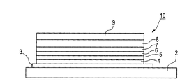
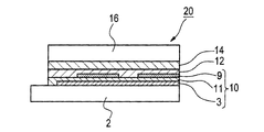
- the organic electroluminescent element of the present invention comprises a substrate, a pair of electrodes arranged on the substrate and consisting of an anode and a cathode, and at least one organic layer disposed between the electrodes and including a light emitting layer, At least one layer of the organic layer contains the compound represented by the general formula (1).
- the structure of the organic electroluminescent element of the present invention is not particularly limited.
- FIG. 1 an example of a structure of the organic electroluminescent element of this invention is shown. 1 has an organic layer on a substrate 2 between a pair of electrodes (anode 3 and cathode 9).
- the element configuration of the organic electroluminescent element, the substrate, the cathode and the anode are described in detail in, for example, Japanese Patent Application Laid-Open No. 2008-270736, and the matters described therein can be applied to the present invention.
- the preferable aspect of the organic electroluminescent element of this invention is demonstrated in detail in order of a board
- the organic electroluminescent element of the present invention has a substrate.
- the substrate used in the present invention is preferably a substrate that does not scatter or attenuate light emitted from the organic layer.
- the organic electroluminescent element of the present invention is disposed on the substrate and has a pair of electrodes including an anode and a cathode.
- a pair of electrodes including an anode and a cathode.
- at least one of the pair of electrodes, the anode and the cathode is preferably transparent or translucent.
- the anode usually has a function as an electrode for supplying holes to the organic layer, and there is no particular limitation on the shape, structure, size, etc., depending on the use and purpose of the light emitting element, It can select suitably from well-known electrode materials.
- the anode is usually provided as a transparent anode.
- the cathode usually has a function as an electrode for injecting electrons into the organic layer, and there is no particular limitation on the shape, structure, size, etc., and it is known depending on the use and purpose of the light-emitting element.
- the electrode material can be selected as appropriate.
- the organic electroluminescent element of the present invention has an organic layer disposed between the electrodes, and the organic layer contains a compound represented by the general formula (1).
- a compound represented by the general formula (1) There is no restriction
- the configuration of the organic layer, the method for forming the organic layer, preferred embodiments of the layers constituting the organic layer, and materials used for the layers will be described in order.
- the organic layer preferably includes a charge transport layer.
- the charge transport layer refers to a layer in which charge transfer occurs when a voltage is applied to the organic electroluminescent element. Specific examples include a hole injection layer, a hole transport layer, an electron block layer, a light emitting layer, a hole block layer, an electron transport layer, and an electron injection layer.
- the organic electroluminescent element of the present invention has a light emitting layer containing the phosphorescent material and other organic layers, and the organic layer contains the compound represented by the general formula (1).
- the said light emitting layer contains the compound represented by the said General formula (1).
- the compound represented by the general formula (1) is used as a host compound of the light emitting layer.
- the organic layer has a light emitting layer containing the phosphorescent material and another organic layer.
- the layers do not necessarily have to be clearly distinguished.
- the organic electroluminescent device of the present invention has an electron transport layer adjacent to the cathode between the pair of electrodes, and an arbitrary hole blocking layer adjacent to the side opposite to the cathode of the electron transport layer. It is also preferred that the electron transport layer or the hole blocking layer contain a compound represented by the general formula (1).
- a plurality of these organic layers may be provided, and when a plurality of layers are provided, they may be formed of the same material, or may be formed of different materials for each layer.
- each organic layer is formed by a dry film forming method such as a vapor deposition method or a sputtering method, a wet film forming method such as a transfer method, a printing method, a spin coating method, or a bar coating method (solution coating method). Any of these can be suitably formed.
- the organic layer disposed between the pair of electrodes includes at least one layer formed by vapor deposition of a composition containing the compound represented by the general formula (1). Is preferred.
- the light emitting layer receives holes from an anode, a hole injection layer, or a hole transport layer when an electric field is applied, receives electrons from a cathode, an electron injection layer, or an electron transport layer, and provides a field for recombination of holes and electrons. It is a layer having a function of providing and emitting light.
- the light emitting layer in the present invention is not necessarily limited to light emission by such a mechanism.
- the light emitting layer in the organic electroluminescent element of the present invention preferably contains at least one phosphorescent material.
- the light emitting layer in the organic electroluminescent element of the present invention may be composed of only the phosphorescent material, or may be a mixed layer of a host material and the phosphorescent material.
- the phosphorescent material may be one kind or two or more kinds.
- the host material is preferably a charge transport material.
- the host material may be one kind or two or more kinds, and examples thereof include a configuration in which an electron transporting host material and a hole transporting host material are mixed.
- the light emitting layer may include a material that does not have charge transporting properties and does not emit light.
- the light emitting layer may be a single layer or a multilayer of two or more layers, and each layer may contain the same light emitting material or host material, or each layer may contain a different material. When there are a plurality of light emitting layers, each of the light emitting layers may emit light with different emission colors.
- the thickness of the light emitting layer is not particularly limited, but is usually preferably 2 nm to 500 nm, and more preferably 3 nm to 200 nm, and more preferably 5 nm to 100 nm from the viewpoint of external quantum efficiency. More preferably.
- the light emitting layer contains a compound represented by the general formula (1), and the host material of the light emitting layer is represented by the general formula (1). It is a more preferable embodiment to use a compound.
- the host material is a compound mainly responsible for charge injection and transport in the light-emitting layer, and is a compound that itself does not substantially emit light.
- substantially does not emit light means that the amount of light emitted from the compound that does not substantially emit light is preferably 5% or less, more preferably 3% or less of the total amount of light emitted from the entire device. It means that it is preferably 1% or less.
- the host material other than the compound represented by the general formula (1), the phosphorescent light emitting material, and the compound represented by the general formula (1) will be described in order.
- the compound represented by the said General formula (1) may be used other than the said light emitting layer in the organic electroluminescent element of this invention.
- the element driving voltage is condensed by condensing the ⁇ plane of a compound having an indolocarbazole skeleton or a compound having a skeleton in which a specific position of a carbon atom of the indolocarbazole skeleton is substituted with a nitrogen atom. It can be reduced compared to indolocarbazole which does not have a ring.
- the compounds having an indolocarbazole skeleton described in WO2011 / 042107 and JP2010-087496A mention that the indolocarbazole skeleton is further condensed, but examples of specific compounds It was found that there was a problem with the number of ring members constituting the skeleton and the position of the condensed ring, and it was difficult to achieve both durability and reduced drive voltage.
- the compound represented by the following general formula (1) will be described.
- X 1 ⁇ X 11 each independently represent a CR 0 or N, R 0 is two adjacent of .
- X 1 ⁇ X 11 represent each independently a hydrogen atom or a substituent at least each represent independently a CR 0, two and if R 0 of CR 0 is coupled to each other to form a ring, wherein only one of R 0 of the adjacent two CR 0 is aryl or heteroaryl group wherein the adjacent represented.
- the hydrogen atom in the description of the general formula (1) includes an isotope (deuterium atom and the like), and the atoms constituting the substituent further include the isotope.
- the substituent when referred to as “substituent”, the substituent may be substituted.
- the term “alkyl group” in the present invention includes an alkyl group substituted with a fluorine atom (for example, trifluoromethyl group) and an alkyl group substituted with an aryl group (for example, triphenylmethyl group).
- alkyl group having 1 to 6 carbon atoms it means that all groups including substituted ones have 1 to 6 carbon atoms.
- X 1 to X 11 each independently represent CR 0 or N, and R 0 each independently represents a hydrogen atom or a substituent.
- examples of the substituent represented by R 0 can include the following substituent group A, and the substituent may further have a substituent.
- examples of the further substituent include a group selected from the substituent group A.
- Substituent group A An alkyl group (preferably having 1 to 30 carbon atoms, more preferably 1 to 20 carbon atoms, particularly preferably 1 to 10 carbon atoms, such as methyl, ethyl, n-propyl, isopropyl, t-butyl, n-hexyl, and n-octyl, n-decyl, n-hexadecyl, cyclopropyl, cyclopentyl, cyclohexyl, etc.), alkenyl groups (preferably having 2 to 30 carbon atoms, more preferably 2 to 20 carbon atoms, and particularly preferably carbon numbers).
- alkyl group preferably having 1 to 30 carbon atoms, more preferably 1 to 20 carbon atoms, particularly preferably 1 to 10 carbon atoms, such as methyl, ethyl, n-propyl, isopropyl, t-butyl, n-hexyl, and n-
- alkynyl group preferably having 2 to 30 carbon atoms, more preferably 2 to 20 carbon atoms, particularly preferably carbon number
- aryl group preferably having 6 to 3 carbon atoms
- amino group preferably having 0 to 30 carbon atoms, More preferably, it has 0 to 20 carbon atoms, particularly preferably 0 to 10 carbon atoms, and examples thereof include amino, methylamino, dimethylamino, diethylamino, dibenzylamino, phenylamino, diphenylamino, ditolylamino and the like.
- a group (preferably having 1 to 30 carbon atoms, more preferably 1 to 20 carbon atoms, particularly preferably 1 to 10 carbon atoms, such as methoxy, ethoxy, butoxy, 2-ethylhexyloxy, etc.), aryl An oxy group (preferably having 6 to 30 carbon atoms, more preferably 6 to 20 carbon atoms, particularly preferably Or having 6 to 12 carbon atoms such as phenyloxy, 1-naphthyloxy, 2-naphthyloxy, etc.), a heterocyclic oxy group (preferably having 1 to 30 carbon atoms, more preferably having 1 to 3 carbon atoms).
- acyl groups preferably 2 to 30 carbon atoms, more preferably 2 to 20 carbon atoms, especially Preferably, it has 2 to 12 carbon atoms, and examples thereof include acetyl, benzoyl, formyl, pivaloyl, etc.), an alkoxycarbonyl group (preferably 2 to 30 carbon atoms, more preferably 2 to 20 carbon atoms, particularly preferably carbon atoms).
- An aryloxycarbonyl group (preferably having 7 to 30 carbon atoms, more preferably 7 to 20 carbon atoms, particularly preferably 7 to 12 carbon atoms, and examples thereof include phenyloxycarbonyl and the like.
- An acyloxy group (preferably having 2 to 30 carbon atoms, more preferably 2 to 20 carbon atoms, particularly preferably 2 to 10 carbon atoms, such as acetoxy, benzoyloxy, etc.), an acylamino group (preferably 2-30 carbon atoms, more preferably 2-20 carbon atoms, particularly preferably 2-10 carbon atoms, and examples thereof include acetylamino, benzoylamino and the like, and alkoxycarbonylamino groups (preferably having 2-2 carbon atoms).
- an aryloxycarbonylamino group preferably having 7 to 30 carbon atoms, more preferably 7 to 20 carbon atoms, particularly preferably 7 to 12 carbon atoms, such as phenyloxycarbonyl And sulfonylamino groups (preferably having 1 to 30 carbon atoms, more preferably 1 to 20 carbon atoms, particularly preferably 1 to 12 carbon atoms, such as methanesulfonylamino and benzenesulfonylamino).
- an aryloxycarbonylamino group preferably having 7 to 30 carbon atoms, more preferably 7 to 20 carbon atoms, particularly preferably 7 to 12 carbon atoms, such as phenyloxycarbonyl And sulfonylamino groups (preferably having 1 to 30 carbon atoms, more preferably 1 to 20 carbon atoms, particularly preferably 1 to 12 carbon atoms, such as methanesulfonylamino and benzenesulfonylamino).
- a sulfamoyl group (preferably having 0 to 30 carbon atoms, more preferably 0 to 20 carbon atoms, particularly preferably 0 to 12 carbon atoms, such as sulfamoyl, methylsulfamoyl, dimethylsulfamoyl, phenyl Sulfamoyl, etc.), carbamoyl groups (preferably having 1 to 30 carbon atoms, more preferably 1 to 20 carbon atoms, particularly preferably 1 to 12 carbon atoms, such as carbamoyl, methylcarbamoyl, diethylcarbamoyl, Phenylcarbamoyl etc.), alkylthio group ( Preferably, it has 1 to 30 carbon atoms, more preferably 1 to 20 carbon atoms, particularly preferably 1 to 12 carbon atoms, such as methylthio, ethylthio, etc.), an arylthio group (preferably 6 to 30 carbon atoms).
- Rufinyl group (preferably having 1 to 30 carbon atoms, more preferably 1 to 20 carbon atoms, particularly preferably 1 to 12 carbon atoms, and examples thereof include methanesulfinyl and benzenesulfinyl. ), A ureido group (preferably having 1 to 30 carbon atoms, more preferably 1 to 20 carbon atoms, particularly preferably 1 to 12 carbon atoms, such as ureido, methylureido, phenylureido, etc.), phosphoric acid An amide group (preferably having 1 to 30 carbon atoms, more preferably 1 to 20 carbon atoms, particularly preferably 1 to 12 carbon atoms, such as diethyl phosphoric acid amide and phenyl phosphoric acid amide), a hydroxy group , Mercapto group, halogen atom (eg fluorine atom, chlorine atom, bromine atom, iodine atom), sulfo group, carboxyl group,
- a group preferably having 3 to 40 carbon atoms, more preferably 3 to 30 carbon atoms, particularly preferably 3 to 24 carbon atoms, such as trimethylsilyloxy, triphenylsilyloxy, etc.
- phosphoryl group for example, diphenyl A phosphoryl group, a dimethylphosphoryl group, etc.
- substituents may be further substituted, and examples of the further substituent include a group selected from the substituent group A described above.
- R 0 contained in X 1 to X 11 a hydrogen atom, an aryl group or a heteroaryl group is preferable among the substituent group A, and a hydrogen atom or an aryl group is more preferable.
- the aryl group represented by R 0 preferably has 6 to 30 carbon atoms, more preferably 6 to 20 carbon atoms, and particularly preferably 6 to 18 carbon atoms.
- a phenyl group, a xylyl group, a biphenyl group, a terphenyl group, A naphthyl group, an anthranyl group, a triphenylenyl group, etc. are mentioned.
- the heteroaryl group represented by R 0 preferably has 5 to 30 ring members, more preferably 5 to 20 ring members, and particularly preferably 5 to 15 ring members.
- pyridyl group pyrimidyl group, triazyl group, pyrazyl group
- examples include a pyridazyl group, a carbazolyl group, a dibenzothiophenyl group, a dibenzofuranyl group.
- R 0 contained in X 1 to X 11 may further have a substituent represented by the substituent group A as described above, and when it has the further substituent, an aryl group, or A substituent containing at least one of a pyridine ring, a pyrimidine ring, a triazine ring, a cyano group and a carbonyl group is preferable.
- an unsubstituted aryl group, a pyridinyl group, a pyrimidinyl group, a triazinyl group, a cyano group-substituted aryl group, an arylcarbonyl group-substituted aryl group are more preferable, and an unsubstituted aryl group, a triazinyl group, and a cyano group-substituted aryl group are more preferable.
- a group is more preferable, and an unsubstituted aryl group and a cyano group-substituted aryl group are particularly preferable.
- the further substituents that R 0 may have are not connected to each other to form a condensed ring.
- the further substituent that R 0 may have may be further substituted.
- the further substituent which R 0 may have is a pyridinyl group, a pyrimidinyl group or a triazinyl group, it is preferable that any of them is diaryl substitution (preferably diphenyl substitution).
- R 0 representing an aryl group or a heteroaryl group
- R 0 in the formula is not particularly limited except that it is a substituent other than an aryl group or a heteroaryl group.
- a substituent in which a ring formed by bonding to R 0 representing an aryl group or heteroaryl group is a 5-membered ring is preferable from the viewpoint of maintaining the green phosphorescence efficiency.
- Examples of the substituent in which the condensed ring formed by bonding to R 0 representing an aryl group or heteroaryl group is a 5-membered ring include a linking group having an atomic linking chain length of 1 when the condensed ring is formed.
- CR 1 R 2 , NR 3 R 1 to R 3 each independently represents a substituent
- a substituent capable of forming O, S or Se is preferred, and CR 1 R 2 , NR 3 , O or S can be formed
- a substituent is more preferable, a substituent capable of forming O or S is particularly preferable, and a substituent capable of forming O is particularly preferable.
- CR 0 is 2 to 11, preferably 5 to 11, more preferably 8 to 11, and particularly preferably 9 to 11. 10 or 11 is more particularly preferred, and 11 is even more particularly preferred.
- the number of CR 0 R 0 is a substituent of X 1 ⁇ X 11, including R 0 which is what R 0 are combined to form a ring together, from 2 to 11, 3-8 Preferably, the number is 3, or more preferably 3 or 4.
- the position of CR 0 in which R 0 is a substituent among X 1 to X 11 depends on the position of the ring formed by condensing two CR 0, but at least of X 2 , X 5 and X 10 One is preferable, and at least two of X 2 , X 5 and X 10 are more preferable.
- the number of rings formed by bonding two adjacent CR 0s among X 1 to X 11 to each other is preferably 1 to 3. It is particularly preferable from the viewpoint of significantly increasing the luminous efficiency of green phosphorescence.
- the compound represented by the general formula (1) is preferably a compound represented by any one of the following general formulas (2) to (9).
- Y A1 to Y H1 each independently represent CR 1 R 2 , NR 3 , O, S or Se, and R 1 to R 3 each independently represent a substituent.
- X A1 to X A15 , X B1 to X B15 , X C1 to X C15 , X D1 to X D15 , X E1 to X E15 , X F1 to X F15 , X G1 to X G15 and X H1 to X H15 are independent of each other Represents CR 4 or N, and each CR 4 independently represents a hydrogen atom or a substituent.
- Y A1 represents CR 1 R 2 , NR 3 , O, S or Se, and R 1 to R 3 each independently represents a substituent.
- a preferable range of Y A1 is different from R 0 representing an aryl group or a heteroaryl group among the two adjacent CR 0 in which R 0 is bonded to each other to form a ring in the general formula (1).
- the other range of R 0 is the same as the preferred range of the linking group having an atomic linking chain length of 1 when a condensed ring is formed.
- Examples of the substituent represented by the substituents R 1 and R 2 on the carbon atom include the substituent group A described above, and the substituent on the carbon atom is preferably an alkyl group, a perfluoroalkyl group, an aryl group, A heteroaryl group, a dialkylamino group, a diarylamino group, an alkoxy group, a cyano group, and a fluorine atom, an alkyl group or an aryl group is more preferable, and a methyl group or a phenyl group is particularly preferable.
- Examples of the substituent represented by the substituent R 3 on the nitrogen atom include the following substituent group B.
- Substituent group B An alkyl group (preferably having 1 to 30 carbon atoms, more preferably 1 to 20 carbon atoms, particularly preferably 1 to 10 carbon atoms, such as methyl, ethyl, isopropyl, tert-butyl, n-octyl, n-decyl, n-hexadecyl, cyclopropyl, cyclopentyl, cyclohexyl, etc.), alkenyl groups (preferably having 2 to 30 carbon atoms, more preferably 2 to 20 carbon atoms, particularly preferably 2 to 10 carbon atoms, such as vinyl , Allyl, 2-butenyl, 3-pentenyl, etc.), alkynyl group (preferably having 2 to 30 carbon atoms, more preferably 2 to 20 carbon atoms, particularly preferably 2 to 10 carbon atoms such as propargyl , 3-pentynyl, etc.), an aryl group (preferably having 6 to
- substituents may be further substituted, and examples of the further substituent include a group selected from the substituent group B described above.
- the substituent on the nitrogen atom represented by R 3 is preferably an alkyl group, an aryl group, or an aromatic heterocyclic group, more preferably an aryl group, and a phenyl group or a phenyl group (biphenyl group) substituted with a phenyl group. Particularly preferred.
- a substituent on the nitrogen atom represented by R 3 of Y A1 and X A15 may be linked to form a ring.
- X A1 to X A15 each independently represent CR 4 or N, and CR 4 each independently represents a hydrogen atom or a substituent.
- the preferred range of X A1 to X A11 is the same as the preferred range of X 1 to X 11 in the general formula (1).
- examples of the substituent represented by R 4 include each independently the substituent group A, and the substituent further includes a substituent. You may have.
- examples of the further substituent include a group selected from the substituent group A.
- R 4 a hydrogen atom, an aryl group or a heteroaryl group is preferable among the substituent group A, and a hydrogen atom or an aryl group is more preferable.
- the aryl group represented by R 4 preferably has 6 to 30 carbon atoms, more preferably 6 to 20 carbon atoms, and particularly preferably 6 to 18 carbon atoms.
- a phenyl group, a xylyl group, a biphenyl group, a terphenyl group, A naphthyl group, an anthranyl group, a triphenylenyl group, etc. are mentioned.
- the heteroaryl group represented by R 4 preferably has 5 to 30 ring members, more preferably 5 to 20 ring members, and particularly preferably 5 to 15 ring members.
- pyridyl group pyrimidyl group, triazyl group, pyrazyl group
- examples include a pyridazyl group, a carbazolyl group, a dibenzothiophenyl group, a dibenzofuranyl group.
- R 4 contained in X A12 to X A15 may further have a substituent represented by the substituent group A as described above, and when it has the further substituent, an aryl group, or A substituent containing at least one of a pyridine ring, a pyrimidine ring, a triazine ring, a cyano group and a carbonyl group is preferable. Among them, an aryl group-substituted aryl group is more preferable, and the further substituent that R 4 may have is particularly preferably further substituted.
- R 4 is preferably a phenyl group-substituted phenyl group (biphenyl group) or a cyano group-substituted phenyl group-substituted aryl group-substituted phenyl group.
- the number of CR 4 is preferably 1 to 4, more preferably 2 to 4, more preferably 3 or 4, and more preferably 4. Is even more particularly preferred.
- the number of CR 4 R 4 is a substituent of X A12 ⁇ X A15 is preferably 0 or 1, and more preferably zero.
- the position of CR 4 when R 4 has CR 4 as a substituent among X A12 to X A15 is at least 1 at the position adjacent to Y A1 (the position of X A15 in the general formula (2)). It is preferable to have one, and it is more preferable to have only one at a position adjacent to Y A1 .
- the general formula (2) is more preferably represented by the general formula (10) described later.
- Y B1 represents CR 1 R 2 , NR 3 , O, S or Se, and R 1 to R 3 each independently represents a substituent.
- the preferred range of Y B1 is the same as the preferred range of Y A1 in the general formula (2).
- a substituent on the nitrogen atom represented by R 3 of Y B1 and X B1 or X B12 may be linked to form a ring.
- X B1 to X B15 each independently represent CR 4 or N, and CR 4 each independently represents a hydrogen atom or a substituent.
- the preferred range of X B1 to X B15 is the same as the preferred range of X A1 to X A15 in the general formula (2).
- the preferred relationship between Y B1 and X B1 to X B15 in the general formula (3) is the same as the preferred relationship between Y A1 and X A1 to X A15 in the general formula (2), that is, X B12 to X B15 are
- the position of CR 4 is preferably a position adjacent to Y B1 (the position of X B12 in the general formula (3)).
- the general formula (3) is more preferably represented by the general formula (11) described later.
- Y C1 represents CR 1 R 2 , NR 3 , O, S or Se, and R 1 to R 3 each independently represent a substituent.
- the preferred range of Y C1 is the same as the preferred range of Y A1 in the general formula (2).
- a substituent on the nitrogen atom represented by R 3 of Y C1 and X C6 or X C15 may be linked to form a ring.
- X C1 to X C15 each independently represent CR 4 or N, and CR 4 each independently represents a hydrogen atom or a substituent.
- the preferred range of X C1 to X C15 is the same as the preferred range of X A1 to X A15 in the general formula (2).
- the preferred relationship between Y C1 and X C1 to X C15 in the general formula (4) is the same as the preferred relationship between Y A1 and X A1 to X A15 in the general formula (2), that is, X C12 to X C15 are
- the position of CR 4 is preferably a position adjacent to Y C1 (the position of X C15 in the general formula (4)).
- the general formula (4) is more preferably represented by the general formula (12) described later.
- Y D1 represents CR 1 R 2 , NR 3 , O, S or Se, and R 1 to R 3 each independently represent a substituent.
- the preferred range of Y D1 is the same as the preferred range of Y A1 in the general formula (2).
- a substituent on the nitrogen atom represented by R 3 of Y D1 and X D12 may be linked to form a ring.
- X D1 to X D15 each independently represent CR 4 or N, and CR 4 each independently represents a hydrogen atom or a substituent.
- the preferred range of X D1 to X D15 is the same as the preferred range of X A1 to X A15 in the general formula (2).
- the preferable relationship between Y D1 and X D1 to X D15 in the general formula (5) is the same as the preferable relationship between Y A1 and X A1 to X A15 in the general formula (2), that is, X D12 to X D15 are
- the CR 4 position in the case of having the substituent CR 4 is preferably a position adjacent to Y D1 (in the general formula (5), the position of X D12 ).
- the general formula (5) is more preferably represented by the general formula (13) described later.
- Y E1 represents CR 1 R 2 , NR 3 , O, S or Se, and R 1 to R 3 each independently represent a substituent.
- the preferable range of Y E1 is the same as the preferable range of Y A1 in the general formula (2).
- a substituent on the nitrogen atom represented by R 3 of Y E1 and X E7 or X E15 may be linked to form a ring.
- X E1 to X E15 each independently represent CR 4 or N, and CR 4 each independently represents a hydrogen atom or a substituent.
- the preferred range of X E1 to X E15 is the same as the preferred range of X A1 to X A15 in the general formula (2).
- the preferable relationship between Y E1 and X E1 to X E15 in the general formula (6) is the same as the preferable relationship between Y A1 and X A1 to X A15 in the general formula (2), that is, X E12 to X E15 are
- the position of CR 4 is preferably a position adjacent to Y E1 (the position of X E15 in the general formula (6)).
- the general formula (6) is more preferably represented by the general formula (14) described later.
- Y F1 represents CR 1 R 2 , NR 3 , O, S or Se, and R 1 to R 3 each independently represents a substituent.
- the preferred range of Y F1 is the same as the preferred range of Y A1 in the general formula (2).
- a substituent on the nitrogen atom represented by R 3 of Y F1 and X F4 or X E12 may be linked to form a ring.
- X F1 to X F15 each independently represent CR 4 or N, and CR 4 each independently represents a hydrogen atom or a substituent.
- the preferred range of X F1 to X F15 is the same as the preferred range of X A1 to X A15 in the general formula (2).
- the preferred relationship between Y F1 and X F1 to X F15 in the general formula (7) is the same as the preferred relationship between Y A1 and X A1 to X A15 in the general formula (2), that is, X F12 to X F15 are
- the position of CR 4 is preferably a position adjacent to Y F1 (the position of X F12 in the general formula (7)).
- the general formula (7) is more preferably represented by the general formula (15) described later.
- Y G1 represents CR 1 R 2 , NR 3 , O, S or Se, and R 1 to R 3 each independently represent a substituent.
- the preferable range of Y G1 is the same as the preferable range of Y A1 in the general formula (2).
- a substituent on the nitrogen atom represented by R 3 of Y G1 and X G15 may be linked to form a ring.
- X G1 to X G15 each independently represent CR 4 or N, and CR 4 each independently represents a hydrogen atom or a substituent.
- the preferred range of X G1 to X G15 is the same as the preferred range of X A1 to X A15 in the general formula (2).
- the preferable relationship between Y G1 and X G1 to X G15 in the general formula (8) is the same as the preferable relationship between Y A1 and X A1 to X A15 in the general formula (2), that is, X G12 to X G15 are
- the position of CR 4 is preferably a position adjacent to Y G1 (in the general formula (8), the position of X G15 ).
- the general formula (8) is more preferably represented by the general formula (16) described later.
- Y H1 represents CR 1 R 2 , NR 3 , O, S or Se, and R 1 to R 3 each independently represent a substituent.
- the preferred range of Y H1 is the same as the preferred range of Y A1 in the general formula (2).
- a substituent on the nitrogen atom represented by R 3 of Y H1 and X H5 or X H12 may be linked to form a ring.
- X H1 to X H15 each independently represent CR 4 or N, and CR 4 each independently represents a hydrogen atom or a substituent.
- the preferred range of X H1 to X H15 is the same as the preferred range of X A1 to X A15 in the general formula (2).
- the preferred relationship between Y H1 and X H1 to X H15 in the general formula (9) is the same as the preferred relationship between Y A1 and X A1 to X A15 in the general formula (2), that is, X H12 to X H15 are
- the position of CR 4 is preferably a position adjacent to Y H1 (position of X H12 in the general formula (9)).
- the general formula (9) is more preferably represented by the general formula (17) described later.
- the compound represented by the general formula (1) is any one of the general formulas (2), (4) to (7) or (8) among the general formulas (2) to (9). Is preferable from the viewpoint that the molecular planarity and stability are good, and that T 1 can be made higher than that of the light-emitting material described later, and the general formulas (2), (4) to (4)-( The compound represented by either 6) or (8) is more preferable from the viewpoint of easily increasing T 1 as compared with the light emitting material described later.
- the compound represented by the general formula (1) is preferably a compound represented by any one of the following general formulas (10) to (17).
- Y A1 to Y H1 each independently represent CR 1 R 2 , NR 3 , O or S or Se, and R 1 to R 3 each independently represent a substituent.
- R A1 to R A15 , R B1 to R B15 , R C1 to R C15 , R D1 to R D15 , R E1 to R E15 , R F1 to R F15 , R G1 to R G15, and R H1 to R H15 are independent of each other. Represents a hydrogen atom or a substituent.
- R A1 to R A15 each independently represents a hydrogen atom or a substituent
- the preferred range of R A1 to R A15 is that all of X A1 to X A15 in the general formula (2) are CR In the case of representing 4 , it is the same as the preferable range of R 4 which each X A1 to X A15 has.
- R B1 to R B15 each independently represents a hydrogen atom or a substituent
- the preferred range of R B1 to R B15 is that all of X B1 to X B15 in the general formula (3) are CR In the case of representing 4 , it is the same as the preferable range of R 4 of each X B1 to X B15 .
- R C1 to R C15 each independently represents a hydrogen atom or a substituent
- the preferred range of R C1 to R C15 is that all of X C1 to X C15 in the general formula (4) are CR In the case of representing 4 , it is the same as the preferable range of R 4 of each X C1 to X C15 .
- R C1 ⁇ R C15 includes a Y C1 in the general formula (4), wherein if X C1 ⁇ X C15 in the general formula (4) represent all CR 4 is the same as the preferred relationship between R 4 each X C1 ⁇ X C15 has at, that is, the position of the substituents in the case where R C12 ⁇ R C15 is substituted, position adjacent to Y C1 (formula ( In 12), the position is preferably R C15 .
- R D1 to R D15 each independently represents a hydrogen atom or a substituent, and preferred ranges of R D1 to R D15 are such that X D1 to X D15 in the general formula (5) are all CR In the case of representing 4 , it is the same as the preferable range of R 4 which each X D1 to X D15 has.
- R D1 ⁇ R D15 includes a Y D1 in the general formula (2), wherein if X D1 ⁇ X D15 in the general formula (5) represent all CR 4 is the same as the preferred relationship between R 4 each X D1 ⁇ X D15 has at, that is, the position of the substituents in the case where R D12 ⁇ R D15 has a substituent, the position adjacent to Y D1 (formula ( In 13), the position is preferably R D12 .
- R E1 to R E15 each independently represents a hydrogen atom or a substituent
- the preferred range of R E1 to R E15 is that all of X E1 to X E15 in the general formula (6) are CR In the case of representing 4 , it is the same as the preferable range of R 4 which each X E1 to X E15 has.
- Preferred relation Y E1 and R E1 ⁇ R E15 in the general formula (14) includes a Y E1 in Formula (6), when said general formula (6) X E1 ⁇ X E15 in represent all CR 4 In X 4 , X E1 to X E15 have the same relationship with R 4. That is, when R E12 to R E15 have a substituent, the position of the substituent is the position adjacent to Y E1 (the above general formula ( In 14), the position is preferably R E15 .
- R F1 to R F15 each independently represents a hydrogen atom or a substituent
- the preferred range of R F1 to R F15 is that all of X F1 to X F15 in the general formula (7) are CR In the case of representing 4 , it is the same as the preferable range of R 4 which each X F1 to X F15 has.
- each of X F1 to X F15 has the same preferable relationship with R 4 , that is, when R F12 to R F15 have a substituent, the position of the substituent is a position adjacent to Y F1 (the above general formula ( In 15), the position is preferably R F12 .
- Y G1 is the same as the definitions and preferable ranges of Y G1 in the general formula (8). Further, a substituent on the nitrogen atom represented by R 3 of Y G1 and X G15 may be linked to form a ring.
- R G1 to R G15 each independently represents a hydrogen atom or a substituent, and preferred ranges of R G1 to R G15 are such that X G1 to X G15 in the general formula (8) are all CR In the case of representing 4 , it is the same as the preferable range of R 4 which each X G1 to X G15 has.
- Formula (16) preferably relationship Y G1 and R G1 ⁇ R G15 in includes a Y G1 in the general formula (8), wherein if X G1 ⁇ X G15 in the general formula (8) represent all CR 4 Is the same as the preferred relationship with R 4 of each X G1 to X G15 , that is, when R G12 to R G15 have a substituent, the position of the substituent is the position adjacent to Y G1 (the above general formula ( In 16), the position of R G15 is preferable.
- R H1 to R H15 each independently represents a hydrogen atom or a substituent
- the preferred range of R H1 to R H15 is that all of X H1 to X H15 in the general formula (9) are CR In the case of representing 4 , it is the same as the preferable range of R 4 which each X H1 to X H15 has.
- Preferred relation Y H1 and R H1 ⁇ R H15 in the general formula (17) includes a Y H1 in Formula (9), when said general formula (9) X H1 ⁇ X H15 in represent all CR 4 In X H1 to X H15 have the same relationship as R 4 , that is, when R H12 to R H15 have a substituent, the position of the substituent is a position adjacent to Y H1 (the above general formula ( In 17), the position of R H12 is preferred.
- the compound represented by the general formula (1) is any one of the general formulas (10), (12) to (15) or (16) among the general formulas (10) to (17). Is preferable from the viewpoint that the planarity and stability of the molecule are good and that T 1 can be easily increased as compared with the light emitting material described later, and the compounds represented by the general formulas (10), (12) to (12) It is more preferable that it is a compound represented by either 14) or (16) from the viewpoint of making T 1 higher than the light emitting material described later.
- the molecular weight of the compound represented by the general formula (1) is usually 400 or more and 1500 or less, preferably 450 or more and 1200 or less, more preferably 500 or more and 1100 or less, and more preferably 550 or more and 1000 or less. Is more preferable.
- the molecular weight is 450 or more, it is advantageous for forming a high-quality amorphous thin film, and when the molecular weight is 1200 or less, the solubility and sublimation property are improved, which is advantageous for improving the purity of the compound.
- the molecular weight of the compound represented by the general formula (1) is preferably 550 or more from the viewpoint of the glass transition temperature.
- the molecular weight of the compound represented by the general formula (1) is preferably 1200 or less.
- the compound represented by the general formula (1) When the compound represented by the general formula (1) is used as a host material of a light emitting layer of an organic electroluminescence device or a charge transport material of a layer adjacent to the light emitting layer, an energy gap in a thin film state from a light emitting material described later.
- the light emitting material described later is a phosphorescent light emitting material, a large minimum triplet (T 1 ) energy in a thin film state
- T 1 a large minimum triplet energy in a thin film state
- it is preferable that the energy gap and T 1 energy are not too large.
- the compound represented by the general formula (1) when the LUMO value of the compound represented by the general formula (1) is determined by an electron density functional method (B3LYP / 6-31G (d) level), Preferably, the compound is 1.4 or more, more preferably 1.4 to 1.9.
- the T 1 energy in the film state of the compound represented by the general formula (1) is preferably 1.77 eV (40 kcal / mol) or more and 3.51 eV (81 kcal / mol) or less and preferably 2.39 eV (55 kcal). / Mol) and more preferably 3.25 eV (75 kcal / mol) or less.
- the T 1 energy is 2.39 eV (55 kcal / mol) or more and 2.82 eV (65 kcal / mol) from the viewpoint of emission efficiency. mol) or less.
- the T 1 energy can be obtained from the short wavelength end of a phosphorescence emission spectrum of a thin film of material. For example, a material is deposited on a cleaned quartz glass substrate to a thickness of about 50 nm by vacuum deposition, and the phosphorescence emission spectrum of the thin film is measured at F-7000 Hitachi Spectrofluorimeter (Hitachi High Technologies) under liquid nitrogen temperature. Use to measure. T 1 energy can be obtained by converting the rising wavelength on the short wavelength side of the obtained emission spectrum into energy units.
- the organic electroluminescent element of the present invention has the general formula (
- the compound represented by 1) is preferably a compound having a glass transition temperature of 100 ° C. or higher.
- the glass transition temperature (Tg) of the compound represented by the general formula (1) is more preferably from 100 ° C to 400 ° C, particularly preferably from 120 ° C to 400 ° C, and from 140 ° C to 400 ° C. More preferably, it is as follows.
- the purity of the compound represented by the general formula (1) When the purity of the compound represented by the general formula (1) is low, impurities work as traps for charge transport or promote deterioration of the device. Therefore, the purity of the compound represented by the general formula (1) The higher the better.
- the purity can be measured by, for example, high performance liquid chromatography (HPLC), and the area ratio of the compound represented by the general formula (1) when detected with a light absorption intensity of 254 nm is preferably 95.0% or more, and more It is preferably 97.0% or more, particularly preferably 99.0% or more, and most preferably 99.9% or more.
- Examples of a method for increasing the purity of the compound represented by the general formula (1) include recrystallization and sublimation purification.
- R A1 , R A4 , R A6 to R A9 , and R A11 to R A14 represent a hydrogen atom, and the other groups are groups described in the following table.
- R B1 , R B4 , R B6 to R B9 , R B11 , R B13 to R B15 represent hydrogen atoms, and other groups are groups described in the following table. is there.
- R C1 , R C3 , R C6 to R C9 and R C11 to R C14 represent hydrogen atoms, and the other groups are groups described in the following table.
- R D1 , R D3 , R D6 to R D9 , R D11 , R D13 to R D15 represent hydrogen atoms, and other groups are groups described in the following table. is there.
- R E1 , R E3 , R E4 , R E7 to R E9 , R E11 , R E13 to R E15 represent hydrogen atoms, and other groups are described in the following table. It is the basis of.
- R F1 , R F3 , R F4 , R F7 to R F9 , R F11 , R F13 to R F15 represent hydrogen atoms, and other groups are listed in the following table It is the basis of.
- R G1 , R G3 , R G4 , R G5 , R G8 , R G9 , R G11 , R G12 to R G14 represent a hydrogen atom, and other groups are groups described in the following table It is.
- R H1 , R H3 , R H4 , R H5 , R H8 , R H9 , R H11 , R H13 to R H15 represent a hydrogen atom. It is a group described in the table.
- the compounds exemplified as the compound represented by the general formula (1) can be synthesized by the methods described in, for example, WO2010 / 042107, WO2010 / 131855, and JP2010-087496.
- the compounds represented by the general formulas (2) to (9) can be preferably synthesized by the following schemes, respectively. However, the following synthesis scheme is an example of synthesis and can be synthesized by another known method. Synthesis route of general formula (2)
- the compound represented by the general formula (1) is not limited in its use and may be contained in any layer in the organic layer.
- Examples of the introduction layer of the compound represented by the general formula (1) include the light emitting layer, a layer between the light emitting layer and the cathode (particularly, a layer adjacent to the light emitting layer), and between the light emitting layer and the anode. It is preferably contained in any one of these layers, more preferably contained in any one or more of the light emitting layer, electron transport layer, electron injection layer, exciton block layer, hole block layer, electron block layer.
- the compound represented by the said General formula (1) is contained in any one of the light emitting layer, the electron transport layer, the hole blocking layer, and the hole transport layer, and particularly preferably contained in the light emitting layer or the electron transport layer.
- the compound represented by the general formula (1) is contained in the light emitting layer, the compound represented by the general formula (1) is included in an amount of 0.1 to 99% by mass with respect to the total mass of the light emitting layer.
- the content is preferably 1 to 97% by mass, more preferably 10 to 96% by mass.
- the compound represented by the general formula (1) is further contained in a layer other than the light emitting layer, it is preferably contained in an amount of 50 to 100% by mass with respect to the total mass of the layer other than the light emitting layer. More preferably, it is contained by mass%.
- the light emitting layer has at least one phosphorescent material.
- a fluorescent light emitting material or a phosphorescent light emitting material different from the phosphorescent light emitting material contained in the light emitting layer can be used as the light emitting material. Details of these fluorescent materials and phosphorescent materials are described in, for example, paragraph numbers [0100] to [0164] of JP-A-2008-270736 and paragraph numbers [0088] to [0090] of JP-A-2007-266458. The matters described in these publications can be applied to the present invention.
- Examples of phosphorescent light-emitting materials that can be used in the present invention include US Pat. / 19373A2, JP-A No. 2001-247859, JP-A No. 2002-302671, JP-A No. 2002-117978, JP-A No. 2003-133074, JP-A No. 2002-1235076, JP-A No. 2003-123984, JP-A No. 2002-170684, EP No. 121157, JP-A No.
- Examples of such a light emitting material include Ir complex, Pt complex, Cu complex, Re complex, W complex, Rh complex, Ru complex, Pd complex, Os complex, Eu complex, Tb complex, Gd.
- Examples include phosphorescent metal complex compounds such as complexes, Dy complexes, and Ce complexes.
- an Ir complex, a Pt complex, or a Re complex among which an Ir complex or a Pt complex containing at least one coordination mode of a metal-carbon bond, a metal-nitrogen bond, a metal-oxygen bond, and a metal-sulfur bond. Or Re complexes are preferred. Furthermore, from the viewpoints of luminous efficiency, driving durability, chromaticity and the like, an Ir complex and a Pt complex are particularly preferable, and an Ir complex is most preferable.
- These phosphorescent metal complex compounds are preferably contained in the light emitting layer together with the compound represented by the general formula (1).
- an iridium complex represented by the following general formula (E-1) As the phosphorescent material contained in the light emitting layer, it is preferable to use an iridium complex represented by the following general formula (E-1). Hereinafter, the iridium complex represented by the general formula (E-1) will be described.
- Z 1 and Z 2 each independently represents a carbon atom or a nitrogen atom.
- a 1 represents an atomic group that forms a 5- or 6-membered heterocycle with Z 1 and a nitrogen atom.
- B 1 represents an atomic group that forms a 5- or 6-membered ring with Z 2 and a carbon atom.
- (XY) represents a monoanionic bidentate ligand.
- n E1 represents an integer of 1 to 3.
- n E1 represents an integer of 1 to 3, preferably 2 or 3.
- Z 1 and Z 2 each independently represents a carbon atom or a nitrogen atom.
- Z 1 and Z 2 are preferably carbon atoms.
- a 1 represents an atomic group that forms a 5- or 6-membered heterocycle with Z 1 and a nitrogen atom.
- the 5- or 6-membered heterocycle containing A 1 , Z 1 and a nitrogen atom includes a pyridine ring, pyrimidine ring, pyrazine ring, triazine ring, imidazole ring, pyrazole ring, oxazole ring, thiazole ring, triazole ring, oxadiazole Ring, thiadiazole ring and the like.
- the 5- or 6-membered hetero ring formed by A 1 , Z 1 and a nitrogen atom is preferably a pyridine ring, a pyrazine ring, an imidazole ring or a pyrazole.
- the 5- or 6-membered heterocycle formed by A 1 , Z 1 and a nitrogen atom may have a substituent, and the substituent group A can be applied as the substituent.
- the substituent is appropriately selected for controlling the emission wavelength and potential, but in the case of shortening the wavelength, an electron donating group, a fluorine atom, and an aromatic ring group are preferable.
- an alkyl group, a dialkylamino group, an alkoxy group, A fluorine atom, an aryl group, a heteroaryl group and the like are selected.
- an electron withdrawing group is preferable, and for example, a cyano group or a perfluoroalkyl group is preferably selected.
- an alkyl group, a cycloalkyl group, an aryl group or the like is preferably selected.
- the substituent on carbon is preferably an alkyl group, a perfluoroalkyl group, an aryl group, a heteroaryl group, a dialkylamino group, a diarylamino group, an alkoxy group, a cyano group, or a fluorine atom.
- the substituent on nitrogen is preferably an alkyl group, an aryl group, or a heteroaryl group, and an alkyl group or an aryl group is preferable from the viewpoint of the stability of the complex.
- the substituents may be linked to each other to form a condensed ring.
- the formed ring includes a benzene ring, a pyridine ring, a pyrazine ring, a pyridazine ring, a pyrimidine ring, an imidazole ring, an oxazole ring, a thiazole ring, and a pyrazole. Ring, thiophene ring, furan ring and the like. These formed rings may have a substituent, and examples of the substituent include the substituent on the carbon atom and the substituent on the nitrogen atom.
- B 1 represents a 5- or 6-membered ring containing Z 2 and a carbon atom.
- Examples of the 5- or 6-membered ring formed by B 1 , Z 2 and a carbon atom include a benzene ring, a pyridine ring, a pyrimidine ring, a pyrazine ring, a pyridazine ring, a triazine ring, an imidazole ring, a pyrazole ring, an oxazole ring, a thiazole ring, Examples include a triazole ring, an oxadiazole ring, a thiadiazole ring, a thiophene ring, and a furan ring.
- the benzene ring, pyridine ring, pyrazine ring, imidazole ring, pyrazole is preferable as the 5- or 6-membered ring formed by B 1 , Z 2 and carbon atom.
- the 5- or 6-membered ring formed of B 1 , Z 2 and a carbon atom may have a substituent, and the substituent group A is a substituent on a nitrogen atom as a substituent on the carbon atom.
- the substituent group B can be applied.
- the substituent on carbon is preferably an alkyl group, a perfluoroalkyl group, an aryl group, a heteroaryl group, a dialkylamino group, a diarylamino group, an alkoxy group, a cyano group, or a fluorine atom.
- the substituent on the carbon is appropriately selected for controlling the emission wavelength and potential, but in the case of increasing the wavelength, an electron donating group and an aromatic ring group are preferable, for example, an alkyl group, a dialkylamino group, an alkoxy group. , Aryl groups, heteroaryl groups and the like are selected.
- an electron withdrawing group is preferable, and for example, a fluorine atom, a cyano group, a perfluoroalkyl group, and the like are selected.
- an alkyl group, a cycloalkyl group, an aryl group or the like is preferably selected.
- the substituent on nitrogen is preferably an alkyl group, an aryl group or an aromatic heterocyclic group, and an alkyl group or an aryl group is preferred from the viewpoint of the stability of the complex.
- the substituents may be linked to each other to form a condensed ring.
- the formed ring includes a benzene ring, a pyridine ring, a pyrazine ring, a pyridazine ring, a pyrimidine ring, an imidazole ring, an oxazole ring, a thiazole ring, and a pyrazole. Ring, thiophene ring, furan ring and the like.
- These formed rings may have a substituent, and examples of the substituent include the substituent on the carbon atom and the substituent on the nitrogen atom.
- the 5- or 6-membered heterocyclic substituent formed by A 1 , Z 1 and a nitrogen atom is linked to the 5- or 6-membered substituent formed by B 1 , Z 2 and a carbon atom. Then, the same condensed ring as described above may be formed.
- (XY) represents a bidentate monoanionic ligand. Examples of bidentate monoanionic ligands are described on pages 89-90 of Lamansky et al., WO 02/15645.
- the bidentate monoanionic ligand represented by (XY) is preferably a bidentate monoanionic ligand represented by the following general formula (L-1).
- R L1 and R L2 each independently represent an alkyl group, an aryl group, or a heteroaryl group.
- R L3 represents a hydrogen atom, an alkyl group, an aryl group, or a heteroaryl group.
- the alkyl group represented by R L1 to R L3 may have a substituent and may be saturated or unsaturated.
- substituent Z ′ examples include the following substituent Z ′, and preferred substituent Z ′ includes a phenyl group, a heteroaryl group, a fluorine atom, a silyl group, an amino group, a cyano group, or a combination thereof. And a phenyl group, a fluorine atom, and a cyano group are more preferable.
- the alkyl group represented by R L1 to R L3 is preferably an alkyl group having 1 to 8 carbon atoms, and more preferably an alkyl group having 1 to 5 carbon atoms.
- Aryl group having 6 to 30 carbon atoms, more preferably 6 to 20 carbon atoms, such as phenyl group, naphthyl group, anthracenyl group, tetracenyl group, pyrenyl group, perylenyl group, triphenylenyl group
- the aryl group represented by R L1 to R L3 may be condensed or may have a substituent.
- substituents include the above-described substituent Z ′, and the substituent Z ′ is preferably an alkyl group or an aryl group, and more preferably an alkyl group.
- the aryl group represented by R L1 to R L3 is preferably an aryl group having 6 to 30 carbon atoms, and more preferably an aryl group having 6 to 18 carbon atoms.
- the heteroaryl group represented by R L1 to R L3 may be condensed or may have a substituent.
- substituent Z ′ examples include the above-described substituent Z ′, and the substituent Z ′ is preferably an alkyl group or an aryl group, and more preferably an alkyl group.
- the heteroaryl group represented by R L1 to R L3 is preferably a heteroaryl group having 4 to 12 carbon atoms, and more preferably a heteroaryl group having 4 to 10 carbon atoms.
- R L1 and R L2 are preferably an alkyl group or an aryl group, more preferably an alkyl group or a phenyl group, and particularly preferably an alkyl group.
- the alkyl group represented by R L1 and R L2 is preferably an alkyl group having 1 to 8 carbon atoms in total, more preferably an alkyl group having 1 to 5 carbon atoms in total, such as a methyl group or an ethyl group N-propyl group, iso-propyl group, iso-butyl group, t-butyl group, n-butyl group, cyclohexyl group and the like, and methyl group, ethyl group, iso-butyl group, or t-butyl group A methyl group is preferable, and a methyl group is particularly preferable.
- R L3 is preferably a hydrogen atom, an alkyl group, or an aryl group, more preferably a hydrogen atom or an alkyl group, and particularly preferably a hydrogen atom.
- a preferred embodiment of the Ir complex represented by the general formula (E-1) is an Ir complex material represented by the following general formula (E-2). Next, general formula (E-2) will be described.
- a E1 to A E8 each independently represents a nitrogen atom or C—R E.
- R E represents a hydrogen atom or a substituent.
- (XY) represents a monoanionic bidentate ligand.
- n E2 represents an integer of 1 to 3.
- a E1 to A E8 each independently represent a nitrogen atom or C—R E.
- R E represents a hydrogen atom or a substituent, and R E may be connected to each other to form a ring. Examples of the ring formed include the same condensed rings described in the general formula (E-1). As the substituent represented by R E , those exemplified as the substituent group A can be applied.
- a E1 ⁇ A E4 is C-R E, if A E1 ⁇ A E4 is C-R E, preferably a hydrogen atom R E of A E3, alkyl group, aryl group, amino group, An alkoxy group, an aryloxy group, a fluorine atom, or a cyano group, more preferably a hydrogen atom, an alkyl group, an amino group, an alkoxy group, an aryloxy group, or a fluorine atom, and particularly preferably a hydrogen atom or a fluorine atom.
- R E in A E1 , A E2 and A E4 is preferably a hydrogen atom, an alkyl group, an aryl group, an amino group, an alkoxy group, an aryloxy group, a fluorine atom, or a cyano group, more preferably a hydrogen atom, An alkyl group, an amino group, an alkoxy group, an aryloxy group, or a fluorine atom, particularly preferably a hydrogen atom.
- a E5 to A E8 are preferably C—R E , and when A E5 to A E8 are C—R E , R E is preferably a hydrogen atom, alkyl group, perfluoroalkyl group, aryl group, aromatic A heterocyclic group, a dialkylamino group, a diarylamino group, an alkyloxy group, a cyano group, or a fluorine atom, more preferably a hydrogen atom, an alkyl group, a perfluoroalkyl group, an aryl group, a dialkylamino group, a cyano group, Or a fluorine atom, and more preferably a hydrogen atom, an alkyl group, a trifluoromethyl group, or a fluorine atom.
- a E6 is preferably a nitrogen atom.
- (X-Y) and n E2 of the general formula in (E1) (X-Y) , and has the same meaning as n E1 preferable ranges are also the same.
- a more preferred form of the compound represented by the general formula (E-2) is a compound represented by the following general formula (E-3).
- R T1 , R T2 , R T3 , R T4 , R T5 , R T6 and R T7 are each independently a hydrogen atom, an alkyl group, a cycloalkyl group, an alkenyl group, an alkynyl group, —CN, perfluoroalkyl group, trifluorovinyl group, —CO 2 R, —C (O) R, —NR 2 , —NO 2 , —OR, halogen atom, aryl group or heteroaryl group, and further substituents Z may be included.
- Each R independently represents a hydrogen atom, an alkyl group, a perhaloalkyl group, an alkenyl group, an alkynyl group, a heteroalkyl group, an aryl group or a heteroaryl group.
- A represents CR ′ or a nitrogen atom
- R ′ represents a hydrogen atom, an alkyl group, a cycloalkyl group, an alkenyl group, an alkynyl group, —CN, a perfluoroalkyl group, a trifluorovinyl group, —CO 2 R, —C (O ) R, —NR 2 , —NO 2 , —OR, a halogen atom, an aryl group or a heteroaryl group, which may further have a substituent Z.
- Each R independently represents a hydrogen atom, an alkyl group, a perhaloalkyl group, an alkenyl group, an alkynyl group, a heteroalkyl group, an aryl group or a heteroaryl group.
- R T1 to R T7 and R ′ may be bonded to each other to form a condensed 4- to 7-membered ring, and the condensed 4- to 7-membered ring is cycloalkyl, aryl or heteroaryl
- the condensed 4- to 7-membered ring may further have a substituent Z.
- R T1 and R T7 , or R T5 and R T6 are condensed to form a benzene ring is preferred, and the case where R T5 and R T6 are condensed to form a benzene ring is particularly preferred.
- Z is independently a halogen atom, -R “, -OR", -N (R ") 2 , -SR", -C (O) R “, -C (O) OR", -C (O) N (R ") 2, -CN , -NO 2, -SO 2, -SOR", - SO 2 R “, or -SO 3 R” represents, R "are each independently a hydrogen atom, an alkyl group, A perhaloalkyl group, an alkenyl group, an alkynyl group, a heteroalkyl group, an aryl group or a heteroaryl group is represented.
- (XY) represents a monoanionic bidentate ligand.
- n E3 represents an integer of 1 to 3.
- the alkyl group may have a substituent, may be saturated or unsaturated, and examples of the group that may be substituted include the above-described substituent Z.
- the alkyl group represented by R T1 to R T7 and R ′ is preferably an alkyl group having 1 to 8 carbon atoms in total, more preferably an alkyl group having 1 to 6 carbon atoms in total, such as methyl Group, ethyl group, i-propyl group, cyclohexyl group, t-butyl group and the like.
- the cycloalkyl group may have a substituent, may be saturated or unsaturated, and examples of the group that may be substituted include the above-described substituent Z.
- the cycloalkyl group represented by R T1 to R T7 and R ′ is preferably a cycloalkyl group having 4 to 7 ring members, more preferably a cycloalkyl group having 5 to 6 carbon atoms in total. A cyclopentyl group, a cyclohexyl group, etc. are mentioned.
- the alkenyl group represented by R T1 to R T7 and R ′ preferably has 2 to 30 carbon atoms, more preferably 2 to 20 carbon atoms, and particularly preferably 2 to 10 carbon atoms.
- vinyl, allyl Examples include 1-propenyl, 1-isopropenyl, 1-butenyl, 2-butenyl, 3-pentenyl and the like.
- the alkynyl group represented by R T1 to R T7 and R ′ preferably has 2 to 30 carbon atoms, more preferably 2 to 20 carbon atoms, and particularly preferably 2 to 10 carbon atoms.
- R T1 to R T7 and R ′ preferably has 2 to 30 carbon atoms, more preferably 2 to 20 carbon atoms, and particularly preferably 2 to 10 carbon atoms.
- Examples of the perfluoroalkyl group represented by R T1 to R T7 and R ′ include those in which all the hydrogen atoms of the aforementioned alkyl group are replaced by fluorine atoms.
- the aryl group represented by R T1 to R T7 and R ′ is preferably a substituted or unsubstituted aryl group having 6 to 30 carbon atoms, such as a phenyl group, a tolyl group, or a naphthyl group.
- the heteroaryl group represented by R T1 to R T7 and R ′ is preferably a heteroaryl group having 5 to 8 carbon atoms, more preferably a 5- or 6-membered substituted or unsubstituted heteroaryl group.
- Groups such as pyridyl, pyrazinyl, pyridazinyl, pyrimidinyl, triazinyl, quinolinyl, isoquinolinyl, quinazolinyl, cinnolinyl, phthalazinyl, quinoxalinyl, pyrrolyl, indolyl, furyl, benzofuryl , Thienyl group, benzothienyl group, pyrazolyl group, imidazolyl group, benzimidazolyl group, triazolyl group, oxazolyl group, benzoxazolyl group, thiazolyl group, benzothiazolyl group, isothiazolyl group, benzis
- R T1 to R T7 and R ′ are preferably a hydrogen atom, an alkyl group, a cyano group, a trifluoromethyl group, a perfluoroalkyl group, a dialkylamino group, a fluoro group, an aryl group, or a heteroaryl group, more preferably A hydrogen atom, an alkyl group, a cyano group, a trifluoromethyl group, a fluoro group, and an aryl group are preferable, and a hydrogen atom, an alkyl group, and an aryl group are more preferable.
- substituent Z an alkyl group, an alkoxy group, a fluoro group, a cyano group, and a dialkylamino group are preferable, and a hydrogen atom is more preferable.
- R T1 to R T7 and R ′ may be bonded to each other to form a condensed 4- to 7-membered ring, and the condensed 4- to 7-membered ring is cycloalkyl, aryl, or heteroaryl;
- the condensed 4- to 7-membered ring may further have a substituent Z.
- the definition and preferred range of cycloalkyl, aryl and heteroaryl formed are the same as the cycloalkyl group, aryl group and heteroaryl group defined by R T1 to R T7 and R ′.
- A represents CR ′, and among R T1 to R T7 and R ′, 0 to 2 are alkyl groups or phenyl groups, and the rest are all hydrogen atoms, and R T1 to R T7 , And R ′ are particularly preferably a case where 0 to 2 are alkyl groups and the rest are all hydrogen atoms.
- n E3 is preferably 2 or 3.
- the type of ligand in the complex is preferably composed of 1 to 2 types, more preferably 1 type.
- the ligand consists of two types from the viewpoint of ease of synthesis.
- (XY) has the same meaning as (XY) in formula (E-1), and the preferred range is also the same.
- One preferred form of the compound represented by the general formula (E-3) is a compound represented by the following general formula (E-4).
- R T1 to R T4 , A, (XY) and n E4 in the general formula (E-4) are R T1 to R T4 , A, (XY) and n E3 in the general formula (E-3).
- the preferred range is also the same.
- R 1 ′ to R 5 ′ are each independently a hydrogen atom, alkyl group, cycloalkyl group, alkenyl group, alkynyl group, —CN, perfluoroalkyl group, trifluorovinyl group, —CO 2 R, —C (O) R.
- Each R independently represents a hydrogen atom, an alkyl group, a perhaloalkyl group, an alkenyl group, an alkynyl group, a heteroalkyl group, an aryl group or a heteroaryl group.
- R 1 ′ to R 5 ′ may be bonded to each other to form a condensed 4- to 7-membered ring, and the condensed 4- to 7-membered ring is cycloalkyl, aryl, or heteroaryl;
- the condensed 4- to 7-membered ring may further have a substituent Z.
- Z is independently a halogen atom, -R “, -OR", -N (R ") 2 , -SR", -C (O) R “, -C (O) OR", -C (O) N (R ") 2, -CN , -NO 2, -SO 2, -SOR", - SO 2 R “, or -SO 3 R” represents, R "are each independently a hydrogen atom, an alkyl group, A perhaloalkyl group, an alkenyl group, an alkynyl group, a heteroalkyl group, an aryl group or a heteroaryl group is represented.
- R 1 ′ to R 5 ′ are the same as R T1 to R T7 and R ′ in formula (E-3). Further, it is particularly preferable that A represents CR ′, and 0 to 2 of R T1 to R T4 , R ′, and R 1 ′ to R 5 ′ are alkyl groups or phenyl groups, and the rest are all hydrogen atoms. More preferably, 0 to 2 of R T1 to R T4 , R ′, and R 1 ′ to R 5 ′ are alkyl groups and the rest are all hydrogen atoms.
- the compounds exemplified as the compound represented by the general formula (E-1) can be synthesized by the method described in JP-A-2009-99783, various methods described in US Pat. No. 7,279,232 and the like. After synthesis, it is preferable to purify by sublimation purification after purification by column chromatography, recrystallization or the like. By sublimation purification, not only can organic impurities be separated, but inorganic salts and residual solvents can be effectively removed.
- the phosphorescent light emitting material is preferably contained in the light emitting layer, but its application is not limited and may be further contained in any layer in the organic layer.
- the phosphorescent light-emitting material in the light-emitting layer is preferably contained in the light-emitting layer in an amount of 0.1% by mass to 50% by mass with respect to the total amount of compounds generally forming the light-emitting layer. From the viewpoint of external quantum efficiency, the content is more preferably 1% by mass to 50% by mass, and particularly preferably 2% by mass to 40% by mass.
- host materials examples include compounds having the following structure as a partial structure. it can. Aromatic hydrocarbon, pyrrole, indole, carbazole, azaindole, indolocarbazole, azacarbazole, triazole, oxazole, oxadiazole, pyrazole, imidazole, thiophene, polyarylalkane, pyrazoline, pyrazolone, phenylenediamine, arylamine, amino Substituted chalcone, styrylanthracene, hydrazone, stilbene, silazane, aromatic tertiary amine compound, styrylamine compound, porphyrin compound, polysilane compound, poly (N-vinylcarbazole), aniline copolymer, thiophene oligomer, polythiophene Conductive polymer oligo
- the organic electroluminescent element of the present invention may have other layers other than the light emitting layer.
- an organic layer other than the light emitting layer that the organic layer may have, a hole injection layer, a hole transport layer, a block layer (a hole block layer, an electron block layer, an exciton block layer, etc.), Examples thereof include an electron transport layer.
- Examples of the specific layer configuration include the following, but the present invention is not limited to these configurations.
- the organic electroluminescent element of the present invention preferably includes (A) at least one organic layer preferably disposed between the anode and the light emitting layer.
- Examples of the organic layer (A) preferably disposed between the anode and the light emitting layer include a hole injection layer, a hole transport layer, and an electron block layer from the anode side.
- the organic electroluminescent element of the present invention preferably includes (B) at least one organic layer preferably disposed between the cathode and the light emitting layer.
- Examples of the organic layer (B) preferably disposed between the cathode and the light emitting layer include an electron injection layer, an electron transport layer, and a hole blocking layer from the cathode side.
- an example of a preferred embodiment of the organic electroluminescent element of the present invention is the embodiment described in FIG. 1, and as the organic layer, a hole injection layer 4, a hole transport layer 5, from the anode side 3, In this embodiment, the light emitting layer 6, the hole blocking layer 7, and the electron transport layer 8 are laminated in this order.
- the organic layer a hole injection layer 4, a hole transport layer 5, from the anode side 3.
- the light emitting layer 6, the hole blocking layer 7, and the electron transport layer 8 are laminated in this order.
- other layers other than the light emitting layer which may be included in the organic electroluminescent element of the present invention will be described.
- the hole injection layer and the hole transport layer are layers having a function of receiving holes from the anode or the anode side and transporting them to the cathode side.
- the hole injecting material and hole transporting material used for these layers may be a low molecular compound or a high molecular compound.
- the matters described in paragraph numbers [0165] to [0167] of JP-A-2008-270736 can be applied to the present invention.
- the hole injection layer preferably contains an electron accepting dopant.
- an electron-accepting dopant may be any organic material or inorganic material as long as it can extract electrons from the doped material and generate radical cations.
- TCNQ compounds such as TCNQ
- F 4 -TCNQ tetrafluorotetracyanoquinodimethane
- hexaazatriphenylene compounds such as hexacyanohexaazatriphenylene (HAT-CN, compound LG 101) used in Examples described later, molybdenum oxide Etc.
- the same effect can be obtained by sandwiching only the electron accepting dopant as a thin film between the anode and the hole transport layer.
- this layer is called a hole injection layer.
- the same effect can be obtained by sandwiching an electron-accepting dopant as a thin film in the hole transport layer.
- the hole injection layer sandwiched between the hole transport layers may be a single layer or multiple layers.
- the electron-accepting dopant in the hole injection layer is preferably contained in an amount of 0.01% by mass to 50% by mass, and preferably 0.1% by mass to 40% by mass with respect to the total mass of the compound forming the hole injection layer. %, More preferably 0.2% by mass to 30% by mass.
- the thickness of the hole injection layer is preferably 1 nm to 50 nm, more preferably 3 nm to 30 nm, and even more preferably 5 nm to 20 nm.
- the electron blocking layer is a layer having a function of preventing electrons transported from the cathode side to the light emitting layer from passing through to the anode side.
- an electron blocking layer can be provided as an organic layer adjacent to the light emitting layer on the anode side.
- the organic compound constituting the electron blocking layer for example, those mentioned as the hole transport material described above can be applied.
- the thickness of the electron blocking layer is preferably 1 nm to 500 nm, more preferably 3 nm to 200 nm, and even more preferably 5 nm to 100 nm.
- the electron blocking layer may have a single layer structure composed of one or more of the above-described materials, or may have a multilayer structure composed of a plurality of layers having the same composition or different compositions.
- the T 1 energy in the film state of the organic compound composing the electron blocking layer must be higher than the T 1 energy of the light emitting material in order to prevent energy transfer of excitons generated in the light emitting layer and not to reduce the light emission efficiency. Is preferred.
- (A-3) Material particularly preferably used in the organic layer preferably disposed between the anode and the light emitting layer [compound represented by the general formula (M-1)]
- the organic electroluminescent device of the present invention is represented by at least one of the following general formula (M-1) as a material particularly preferably used for the organic layer preferably disposed between the anode (A) and the light emitting layer. Can be mentioned.
- the compound represented by the general formula (M-1) is more preferably contained in an organic layer adjacent to the light emitting layer between the light emitting layer and the anode, but its use is not limited, and the organic layer It may be further contained in any of the layers.
- the introduction layer of the compound represented by the general formula (M-1) any of a light emitting layer, a hole injection layer, a hole transport layer, an electron transport layer, an electron injection layer, a charge blocking layer, or a plurality of layers can be used. Can be contained.
- the organic layer adjacent to the light emitting layer between the light emitting layer and the anode and containing the compound represented by the general formula (M-1) is more preferably an electron blocking layer or a hole transporting layer.
- Ar 1 and Ar 2 are each independently one or more selected from alkyl, aryl, heteroaryl, arylamino, alkylamino, morpholino, thiomorpholino, N, O, and S Represents a 5- or 6-membered heterocycloalkyl or cycloalkyl containing a heteroatom, and may further have a substituent Z.
- Ar 1 and Ar 2 may be bonded to each other by a single bond, alkylene, or alkenylene (with or without a condensed ring) to form a condensed 5- to 9-membered ring.
- Ar 3 represents P-valent alkyl, aryl, heteroaryl, or arylamino, and may further have a substituent Z.
- Z is independently a halogen atom, -R “, -OR", -N (R ") 2 , -SR", -C (O) R “, -C (O) OR", -C (O) N (R ") 2, -CN , -NO 2, -SO 2, -SOR", - SO 2 R “, or -SO 3 R” represents, R “are each independently a hydrogen atom, an alkyl group, A perhaloalkyl group, an alkenyl group, an alkynyl group, a heteroalkyl group, an aryl group or a heteroaryl group is represented.
- p is an integer of 1 to 4, and when p is 2 or more, Ar 1 and Ar 2 may be the same or different.
- Another preferable embodiment of the compound represented by the general formula (M-1) is a case represented by the following general formula (M-2).
- R M1 represents an alkyl group, an aryl group, or a heteroaryl group.
- R M2 to R M23 each independently represent a hydrogen atom, an alkyl group, an aryl group, a heteroaryl group, an alkoxy group, an aryloxy group, an amino group, a silyl group, a cyano group, a nitro group, or a fluorine atom.
- R M1 represents an alkyl group (preferably having 1 to 8 carbon atoms), an aryl group (preferably having 6 to 30 carbon atoms), or a heteroaryl group (preferably having 4 to 12 carbon atoms). Which may have the aforementioned substituent Z.
- R M1 is preferably an aryl group or a heteroaryl group, more preferably an aryl group.
- Preferred substituents when the aryl group of R M1 has a substituent include an alkyl group, a halogen atom, a cyano group, an aryl group, and an alkoxy group, and an alkyl group, a halogen atom, a cyano group, and an aryl group are more preferable.
- the aryl group of R M1 is preferably a phenyl group that may have a substituent Z, and more preferably a phenyl group that may have an alkyl group or a cyano group.
- R M2 to R M23 are each independently a hydrogen atom, an alkyl group (preferably having 1 to 8 carbon atoms), an aryl group (preferably having 6 to 30 carbon atoms), a heteroaryl group (preferably having 4 to 12 carbon atoms), Alkoxy group (preferably having 1 to 8 carbon atoms), aryloxy group (preferably having 6 to 30 carbon atoms), amino group (preferably having 0 to 24 carbon atoms), silyl group (preferably having 0 to 18 carbon atoms), cyano Represents a group, a nitro group, or a fluorine atom, and these may have the aforementioned substituent Z.
- R M2 , R M7 , R M8 , R M15 , R M16 and R M23 are preferably a hydrogen atom or an alkyl group or an aryl group which may have a substituent Z, more preferably a hydrogen atom.
- R M4 , R M5 , R M11 , R M12 , R M19 and R M20 are preferably a hydrogen atom, an alkyl group or an aryl group which may have a substituent Z, or a fluorine atom, more preferably a hydrogen atom. Is an atom.
- R M3 , R M6 , R M9 , R M14 , R M17 and R M22 are preferably a hydrogen atom, an alkyl or aryl group optionally having substituent Z, a fluorine atom, or a cyano group, and more Preferably they are a hydrogen atom or the alkyl group which may have the substituent Z, More preferably, it is a hydrogen atom.
- R M10 , R M13 , R M18 and R M21 are preferably a hydrogen atom, an alkyl group optionally having a substituent Z, an aryl group, a heteroaryl group or an amino group, a nitro group, a fluorine atom, or a cyano group.
- a hydrogen atom an alkyl or aryl group optionally having a substituent Z, a nitro group, a fluorine atom, or a cyano group, still more preferably a hydrogen atom or a substituent Z.
- It is an alkyl group that may be present.
- the substituent is preferably a fluorine atom
- the alkyl group which may have the substituent Z preferably has 1 to 6 carbon atoms, more preferably 1 to 4 carbon atoms. is there.
- Another preferred embodiment of the compound represented by the general formula (M-1) is a case represented by the following general formula (M-3).
- R S1 to R S5 are each independently an alkyl group, cycloalkyl group, alkenyl group, alkynyl group, —CN, perfluoroalkyl group, trifluorovinyl group, —CO 2 R, — C (O) R, —NR 2 , —NO 2 , —OR, a halogen atom, an aryl group or a heteroaryl group, which may further have a substituent Z.
- Each R independently represents a hydrogen atom, an alkyl group, a perhaloalkyl group, an alkenyl group, an alkynyl group, a heteroalkyl group, an aryl group or a heteroaryl group.
- R S1 to R S5 When a plurality of R S1 to R S5 are present, they may be bonded to each other to form a ring, and may further have a substituent Z.
- a represents an integer of 0 to 4, and when a plurality of R S1 are present, they may be the same or different and may be bonded to each other to form a ring.
- b to e each independently represent an integer of 0 to 5, and when there are a plurality of R S2 to R S5 , respectively, they may be the same or different, and any two may be bonded to form a ring.
- q is an integer of 1 to 5, and when q is 2 or more, a plurality of R S1 may be the same or different, and may be bonded to each other to form a ring.
- the alkyl group may have a substituent, may be saturated or unsaturated, and examples of the group that may be substituted include the above-described substituent Z.
- the alkyl group represented by R S1 to R S5 is preferably an alkyl group having 1 to 8 carbon atoms in total, more preferably an alkyl group having 1 to 6 carbon atoms in total, such as a methyl group or an ethyl group. , I-propyl group, cyclohexyl group, t-butyl group and the like.
- the cycloalkyl group may have a substituent, may be saturated or unsaturated, and examples of the group that may be substituted include the above-described substituent Z.
- the cycloalkyl group represented by R S1 to R S5 is preferably a cycloalkyl group having 4 to 7 ring members, more preferably a cycloalkyl group having 5 to 6 carbon atoms in total, such as a cyclopentyl group or cyclohexyl group. Groups and the like.
- the alkenyl group represented by R S1 to R S5 preferably has 2 to 30 carbon atoms, more preferably 2 to 20 carbon atoms, and particularly preferably 2 to 10 carbon atoms.
- vinyl, allyl, 1-propenyl Examples include 1-isopropenyl, 1-butenyl, 2-butenyl, 3-pentenyl and the like.
- the alkynyl group represented by R S1 to R S5 preferably has 2 to 30 carbon atoms, more preferably 2 to 20 carbon atoms, and particularly preferably 2 to 10 carbon atoms.
- Examples of the perfluoroalkyl group represented by R S1 to R S5 include those in which all the hydrogen atoms of the aforementioned alkyl group are replaced with fluorine atoms.
- the aryl group represented by R S1 to R S5 is preferably a substituted or unsubstituted aryl group having 6 to 30 carbon atoms, such as a phenyl group, a tolyl group, a biphenyl group, and a terphenyl group.
- the heteroaryl group represented by R S1 to R S5 is preferably a heteroaryl group having 5 to 8 carbon atoms, more preferably a 5- or 6-membered substituted or unsubstituted heteroaryl group,
- R S1 to R S5 are preferably a hydrogen atom, an alkyl group, a cyano group, a trifluoromethyl group, a perfluoroalkyl group, a dialkylamino group, a fluoro group, an aryl group, or a heteroaryl group, and more preferably a hydrogen atom, an alkyl group Group, cyano group, trifluoromethyl group, fluoro group and aryl group, more preferably a hydrogen atom, an alkyl group and an aryl group.
- substituent Z an alkyl group, an alkoxy group, a fluoro group, a cyano group, and a dialkylamino group are preferable, and a hydrogen atom and an alkyl group are more preferable.
- R S1 to R S5 may be bonded to each other to form a condensed 4- to 7-membered ring, and the condensed 4- to 7-membered ring is cycloalkyl, aryl, or heteroaryl;
- the 7-membered ring may further have a substituent Z.
- the definition and preferred range of cycloalkyl, aryl, and heteroaryl formed are the same as the cycloalkyl group, aryl group, and heteroaryl group defined by R S1 to R S5 .
- the compound represented by the general formula (M-1) is preferably contained in an amount of 50 to 100% by mass.
- the content is preferably 80 to 100% by mass, and particularly preferably 95 to 100% by mass.
- each layer contains the above-mentioned range.
- the compound represented by the general formula (M-1) may contain only one kind in any organic layer, and a plurality of compounds represented by the general formula (M-1) You may contain combining in a ratio.
- the thickness of the hole transport layer containing the compound represented by the general formula (M-1) is preferably 1 nm to 500 nm, more preferably 3 nm to 200 nm, and 5 nm to 100 nm. Is more preferable.
- the hole transport layer is preferably provided in contact with the light emitting layer.
- the lowest excited triplet (T 1 ) energy in the film state of the compound represented by the general formula (M-1) is 1.77 eV (40 kcal / mol) or more and 3.51 eV (81 kcal / mol) or less. Is preferably 2.39 eV (55 kcal / mol) or more and 3.25 eV (75 kcal / mol) or less.
- T 1 energy of the compound represented by the general formula (M-1) is higher than the T 1 energy of the phosphorescent material. .
- the T 1 energy is 2.39 eV (55 kcal / mol) or more and 2.82 eV (65 kcal / mol) from the viewpoint of emission efficiency. mol) or less.
- the hydrogen atom constituting the general formula (M-1) includes a hydrogen isotope (such as deuterium atom).
- a hydrogen isotope such as deuterium atom.
- all hydrogen atoms in the compound may be replaced with hydrogen isotopes, or a mixture in which a part is a compound containing hydrogen isotopes may be used.
- the compound represented by the general formula (M-1) can be synthesized by combining various known synthesis methods.
- carbazole compounds are synthesized by dehydroaromatization after the Athercorp rearrangement reaction of a condensate of an aryl hydrazine and a cyclohexane derivative (LF Tieze, by Th. Eicher, translated by Takano and Ogasawara, Precision organic synthesis, page 339 (published by Nankodo).
- LF Tieze by Th. Eicher, translated by Takano and Ogasawara, Precision organic synthesis, page 339 (published by Nankodo).
- LF Tieze by Th. Eicher, translated by Takano and Ogasawara, Precision organic synthesis, page 339 (published by Nankodo).
- LF Tieze by Th. Eicher, translated by Takano and Ogasawara, Precision organic synthesis, page 339 (published by Nankodo).
- the compound represented by the general formula (M-1) is preferably formed into a thin layer by a vacuum deposition process, but a wet process such as solution coating can also be suitably used.
- the molecular weight of the compound is preferably 2000 or less, more preferably 1200 or less, and particularly preferably 800 or less from the viewpoints of deposition suitability and solubility. Also, from the viewpoint of vapor deposition suitability, if the molecular weight is too small, the vapor pressure becomes small, the change from the gas phase to the solid phase does not occur, and it is difficult to form an organic layer. Particularly preferred.
- the electron injection layer and the electron transport layer are layers having a function of receiving electrons from the cathode or the cathode side and transporting them to the anode side.
- the electron injection material and the electron transport material used for these layers may be a low molecular compound or a high molecular compound.
- the electron transport material the compound represented by the general formula (1) can be used.
- electron transport materials include pyridine derivatives, quinoline derivatives, pyrimidine derivatives, pyrazine derivatives, phthalazine derivatives, phenanthroline derivatives, triazine derivatives, triazole derivatives, oxazole derivatives, oxadiazole derivatives, imidazole derivatives, benzimidazole derivatives, imidazopyridine derivatives.
- the thicknesses of the electron injection layer and the electron transport layer are each preferably 500 nm or less from the viewpoint of lowering the driving voltage.
- the thickness of the electron transport layer is preferably 1 nm to 500 nm, more preferably 5 nm to 200 nm, and still more preferably 10 nm to 100 nm.
- the thickness of the electron injection layer is preferably from 0.1 nm to 200 nm, more preferably from 0.2 nm to 100 nm, and even more preferably from 0.5 nm to 50 nm.
- the electron injection layer and the electron transport layer may have a single layer structure composed of one or more of the above-described materials, or may have a multilayer structure composed of a plurality of layers having the same composition or different compositions.
- the electron injection layer can contain an electron donating dopant.
- an electron donating dopant By including an electron donating dopant in the electron injection layer, the electron injection property is improved, the driving voltage is lowered, and the efficiency is improved.
- the electron donating dopant may be any organic material or inorganic material as long as it can give electrons to the doped material and generate radical anions.
- TTF tetrathiafulvalene
- TTTT tetrathianaphthacene
- bis- [1,3 diethyl-2-methyl-1,2-dihydrobenzimidazolyl] lithium, cesium and the like.
- the electron donating dopant in the electron injection layer is preferably contained in an amount of 0.01% by mass to 50% by mass, and 0.1% by mass to 40% by mass with respect to the total mass of the compound forming the electron injection layer. More preferably, the content is 0.5 to 30% by mass.
- the hole blocking layer is a layer having a function of preventing holes transported from the anode side to the light emitting layer from passing through to the cathode side.
- a hole blocking layer can be provided as an organic layer adjacent to the light emitting layer on the cathode side.
- the T 1 energy in the film state of the organic compound constituting the hole blocking layer is higher than the T 1 energy of the light emitting material in order to prevent energy transfer of excitons generated in the light emitting layer and not to reduce the light emission efficiency. It is preferable.
- the organic compound constituting the hole blocking layer the compound represented by the general formula (1) can be used.
- Examples of other organic compounds constituting the hole blocking layer other than the compound represented by the general formula (1) include aluminum (III) • tris-8-hydroxyquinoline (abbreviated as Alq), aluminum ( III) Aluminum complexes such as bis (2-methyl-8-quinolinato) 4-phenylphenolate (Aluminum (III) bis (2-methyl-8-quinolinato) 4-phenylphenolate (abbreviated as Balq)), triazole derivatives, Phenanthroline derivatives such as 2,9-dimethyl-4,7-diphenyl-1,10-phenanthroline (2,9-Dimethyl-4,7-diphenyl-1,10-phenanthroline (abbreviated as BCP)), etc. It is done.
- the hole blocking layer is not limited to the function of actually blocking holes, and may have a function of preventing the excitons of the light emitting layer from diffusing into the electron transport layer or blocking energy transfer quenching. .
- the compound of the present invention can also be preferably applied as a hole blocking layer.
- the thickness of the hole blocking layer is preferably 1 nm to 500 nm, more preferably 3 nm to 100 nm, and even more preferably 5 nm to 50 nm.
- the hole blocking layer may have a single layer structure made of one or more of the materials described above, or may have a multilayer structure made of a plurality of layers having the same composition or different compositions.
- the material used for the hole blocking layer is preferably higher than the T 1 energy of the phosphorescent light emitting material in terms of color purity, light emission efficiency, and driving durability.
- the organic electroluminescent element of the present invention is preferably disposed between the (B) cathode and the light emitting layer.
- a material particularly preferably used for the material of the organic layer a compound represented by the general formula (1), an aromatic hydrocarbon compound (particularly, the following general formula (Tp-1)) and a general formula (O— The compound represented by 1) can be mentioned.
- Tp-1 an aromatic hydrocarbon compound
- O— The compound represented by 1 can be mentioned.
- the aromatic hydrocarbon compound and the compound represented by the general formula (O-1) will be described.
- the aromatic hydrocarbon compound is more preferably contained in an organic layer adjacent to the light emitting layer between the light emitting layer and the cathode, but its use is not limited, and any layer in the organic layer may be included. Further, it may be contained.
- the introduction layer of the aromatic hydrocarbon compound is contained in one or more of a light emitting layer, a hole injection layer, a hole transport layer, an electron transport layer, an electron injection layer, an exciton block layer, and a charge block layer. be able to.
- the organic layer adjacent to the light emitting layer between the light emitting layer and the cathode and containing the aromatic hydrocarbon compound is preferably a block layer (hole blocking layer, exciton blocking layer) or an electron transporting layer. More preferably, it is a transport layer.
- the aromatic hydrocarbon compound When the aromatic hydrocarbon compound is contained in a layer other than the light emitting layer, it is preferably contained in an amount of 70 to 100% by mass, more preferably 85 to 100% by mass. When the aromatic hydrocarbon compound is contained in the light emitting layer, it is preferably contained in an amount of 0.1 to 99% by weight, more preferably 1 to 95% by weight, based on the total weight of the light emitting layer. It is more preferable to include the mass%. As the aromatic hydrocarbon compound, it is preferable to use a hydrocarbon compound having a molecular weight of 400 to 1200 and a condensed polycyclic skeleton having a total carbon number of 13 to 22.
- the condensed polycyclic skeleton having 13 to 22 carbon atoms is preferably any one of fluorene, anthracene, phenanthrene, tetracene, chrysene, pentacene, pyrene, perylene, and triphenylene.
- fluorene, triphenylene, phenanthrene Is more preferable, and triphenylene is more preferable from the viewpoint of stability of the compound and charge injection / transport properties, and a compound represented by the following general formula (Tp-1) is particularly preferable.
- the hydrocarbon compound represented by the general formula (Tp-1) preferably has a molecular weight in the range of 400 to 1200, more preferably 400 to 1100, and still more preferably 400 to 000. If the molecular weight is 400 or more, a high-quality amorphous thin film can be formed, and if the molecular weight is 1200 or less, it is preferable in terms of solubility in a solvent, sublimation, and appropriate deposition.
- hydrocarbon compound represented by the general formula (Tp-1) is not limited, and the hydrocarbon compound may be further contained not only in the organic layer adjacent to the light emitting layer but also in any layer in the organic layer. .
- R 12 to R 23 are each independently a hydrogen atom, an alkyl group, a phenyl group, a fluorenyl group, a naphthyl group, or a triphenylenyl group (these are further an alkyl group, a phenyl group, a fluorenyl group, A naphthyl group or a triphenylenyl group).
- R 12 to R 23 are not all hydrogen atoms.
- Examples of the alkyl group represented by R 12 to R 23 are substituted or unsubstituted, for example, methyl group, ethyl group, isopropyl group, n-butyl group, tert-butyl group, n-octyl group, n-decyl group, and an n-hexadecyl group, a cyclopropyl group, a cyclopentyl group, a cyclohexyl group, and the like, preferably a methyl group, an ethyl group, an isopropyl group, a tert-butyl group, and a cyclohexyl group, more preferably a methyl group, an ethyl group, or A tert-butyl group.
- R 12 to R 23 are preferably an alkyl group having 1 to 4 carbon atoms, a phenyl group, a fluorenyl group, a naphthyl group, or a triphenylenyl group (these are further an alkyl group, a phenyl group, a fluorenyl group, a naphthyl group, or a triphenylenyl group). It is more preferably a phenyl group, a fluorenyl group, a naphthyl group, or a triphenylenyl group, which may be substituted with (which may be substituted).
- a benzene ring that may be substituted with a phenyl group, a fluorenyl group, a naphthyl group, or a triphenylenyl group (which may be further substituted with an alkyl group, a phenyl group, a fluorenyl group, a naphthyl group, or a triphenylenyl group); It is particularly preferred.
- the total number of aryl rings is preferably 2 to 8, and preferably 3 to 5. By setting it as this range, a high-quality amorphous thin film can be formed, and solubility in a solvent, sublimation, and deposition suitability are improved.
- R 12 to R 23 each independently preferably has a total carbon number of 20 to 50, and more preferably a total carbon number of 20 to 36. By setting it as this range, a high-quality amorphous thin film can be formed, and solubility in a solvent, sublimation, and deposition suitability are improved.
- the hydrocarbon compound represented by the general formula (Tp-1) is preferably a hydrocarbon compound represented by the following general formula (Tp-2).
- a plurality of Ar 11 are the same, and an alkyl group, a phenyl group, a fluorenyl group, a naphthyl group, or a triphenylenyl group (these are further an alkyl group, a phenyl group, a fluorenyl group, a naphthyl group, or Which may be substituted with a triphenylenyl group).
- an alkyl group, a phenyl group, a fluorenyl group, a naphthyl group, or a triphenylenyl group (these may be further substituted with an alkyl group, a phenyl group, a fluorenyl group, a naphthyl group, or a triphenylenyl group)
- R 12 to R 23 an alkyl group, a phenyl group, a fluorenyl group, a naphthyl group, or a triphenylenyl group
- the hydrocarbon compound represented by the general formula (Tp-1) is preferably a hydrocarbon compound represented by the following general formula (Tp-3).
- L represents an alkyl group, a phenyl group, a fluorenyl group, a naphthyl group, or a triphenylenyl group (these are further substituted with an alkyl group, a phenyl group, a fluorenyl group, a naphthyl group, or a triphenylenyl group).
- n represents an integer of 2 to 6.
- the alkyl group, phenyl group, fluorenyl group, naphthyl group, or triphenylenyl group forming the n-valent linking group represented by L has the same meaning as that described for R 12 to R 23 .
- L is preferably an alkyl group or an n-valent linking group formed by combining a benzene ring, a fluorene ring, or a combination thereof, which may be substituted with a benzene ring.
- L is bonded to the triphenylene ring by *.
- N is preferably from 2 to 5, and more preferably from 2 to 4.
- the compound represented by the general formula (Tp-1) is preferably a compound represented by the following general formula (Tp-4).
- a A1 to A A12 each independently represents CR 400 or a nitrogen atom.
- N 401 represents an integer of 0 to 8.
- the ring represented by A6 represents a single bond between the triphenylene ring and the ring represented by A A7 to A A12.
- n 401 is 2 to 6, it is represented by a plurality of A A1 to A A6.
- the hydrogen atom in the description of the general formula (Tp-4) includes an isotope (deuterium atom, etc.), and the atoms constituting the substituent further include the isotope. To express.
- R 411 to R 421 are each independently a hydrogen atom, an alkyl group, a phenyl group, a fluorenyl group, a naphthyl group, or a triphenylenyl group (these are further an alkyl group, a phenyl group, a fluorenyl group, A naphthyl group or a triphenylenyl group).
- R 411 to R 421 are preferably a hydrogen atom, an alkyl group having 1 to 4 carbon atoms, a phenyl group, a fluorenyl group, a naphthyl group, or a triphenylenyl group (these are further an alkyl group, a phenyl group, a fluorenyl group, a naphthyl group, or It may preferably be substituted with a triphenylenyl group), and may be a hydrogen atom or a phenyl group (the phenyl group may be substituted with an alkyl group, a phenyl group, a fluorenyl group, a naphthyl group, or a triphenylenyl group).
- a A1 to A A12 are preferably CR 400 .
- examples of the substituent represented by R 400 include a hydrogen atom, an alkyl group having 1 to 4 carbon atoms, a phenyl group, a fluorenyl group, a naphthyl group, or a triphenylenyl group (these are further alkyl groups, A phenyl group, a fluorenyl group, a naphthyl group, or a triphenylenyl group).
- a plurality of R 400 may be different from each other.
- R 400 is preferably a hydrogen atom, an alkyl group having 1 to 4 carbon atoms, a phenyl group, a fluorenyl group, a naphthyl group, or a triphenylenyl group (these are further an alkyl group, a phenyl group, a fluorenyl group, a naphthyl group, or a triphenylenyl group).
- n 401 is preferably an integer of 0 to 5, more preferably an integer of 1 to 5, and particularly preferably 2 to 4.
- n 401 is an integer of 1 or more, and when the position connected to the ring represented by A A7 to A A12 is A A3 , the substituent represented by A A4 or A A5 is CR 400 from the viewpoint of luminous efficiency.
- R 400 is preferably an alkyl group having 1 to 4 carbon atoms or a phenyl group, more preferably an alkyl group having 1 to 4 carbon atoms, and particularly preferably a methyl group.
- the number of nitrogen-containing rings is preferably 1 or less, and 0 is preferable. More preferred.
- the connection of each 6-membered aromatic ring composed of A A1 to A A12 is not limited, but is preferably connected at the meta position or the para position.
- the compound represented by the general formula (Tp-4) has a number of aromatic rings continuously connected at the para position including a phenyl ring which is a partial structure of a condensed ring constituting a triphenylene ring. The number is preferably 3 or less.
- the hydrocarbon compound represented by the general formula (Tp-1) When the hydrocarbon compound represented by the general formula (Tp-1)) is used as a host material of a light emitting layer of an organic electroluminescence device or a charge transport material of a layer adjacent to the light emitting layer, the hydrocarbon compound in a thinner state than the light emitting material.
- the energy gap low emission triplet (T 1 ) energy in a thin film state when the light emitting material is a phosphorescent light emitting material
- the energy gap and T 1 energy are not too large.
- the T 1 energy in the film state of the hydrocarbon compound represented by the general formula (Tp-1) is preferably 1.77 eV (40 kcal / mol) or more and 3.51 eV (81 kcal / mol) or less. It is more preferable that it is 39 eV (55 kcal / mol) or more and 3.25 eV (75 kcal / mol) or less.
- the organic electroluminescent element of the present invention it is preferable from the viewpoint of luminous efficiency that the T 1 energy of the compound represented by the general formula (Tp-1) is higher than the T 1 energy of the phosphorescent material. .
- the T 1 energy is 2.39 eV (55 kcal / mol) or more and 2.82 eV (65 kcal / mol) from the viewpoint of emission efficiency. mol) or less.
- T 1 energy of the hydrocarbon compound represented by the general formula (Tp-1) can be obtained by a method similar to the method in the description of the general formula (1).
- the glass transition temperature (Tg) of the hydrocarbon compound according to the present invention is 80 ° C. or more and 400 ° C. or less from the viewpoint of stably operating the organic electroluminescence device against heat generation during high temperature driving or during device driving.
- the temperature is preferably 100 ° C. or higher and 400 ° C. or lower, more preferably 120 ° C. or higher and 400 ° C. or lower.
- the compounds exemplified as the hydrocarbon compound represented by the general formula (Tp-1) include WO05 / 013388 pamphlet, WO06 / 130598 pamphlet, WO09 / 021107 pamphlet, US2009 / 0009065, WO09 / 008311 pamphlet and WO04 / 018587 pamphlet.
- R O1 represents an alkyl group, an aryl group, or a heteroaryl group.
- a O1 to A O4 each independently represent C—R A or a nitrogen atom.
- R A represents a hydrogen atom, an alkyl group, an aryl group, or a heteroaryl group, and a plurality of R A may be the same or different.
- L O1 represents a divalent to hexavalent linking group composed of an aryl ring or a heteroaryl ring.
- n O1 represents an integer of 2 to 6.
- R O1 represents an alkyl group (preferably having 1 to 8 carbon atoms), an aryl group (preferably having 6 to 30 carbon atoms), or a heteroaryl group (preferably having 4 to 12 carbon atoms).
- Group A may be included.
- R O1 is preferably an aryl group or a heteroaryl group, more preferably an aryl group.
- a preferable substituent when the aryl group of R O1 has a substituent includes an alkyl group, an aryl group or a cyano group, more preferably an alkyl group or an aryl group, and still more preferably an aryl group.
- the aryl group of R O1 When the aryl group of R O1 has a plurality of substituents, the plurality of substituents may be bonded to each other to form a 5- or 6-membered ring.
- the aryl group of R O1 is preferably a phenyl group which may have a substituent A, more preferably a phenyl group which an alkyl group or an aryl group may be substituted, and still more preferably an unsubstituted group.
- a O1 to A O4 each independently represent C—R A or a nitrogen atom.
- 0 to 2 are preferably nitrogen atoms, more preferably 0 or 1 is a nitrogen atom.
- all of A O1 ⁇ A O4 is C-R A, or A O1 be a nitrogen atom, is preferably A O2 ⁇ A O4 is C-R A, A O1 be a nitrogen atom, A O2 ⁇ More preferably, A O4 is C—R A , A O1 is a nitrogen atom, A O2 to A O4 are C—R A , and R A is all hydrogen atoms.
- R A represents a hydrogen atom, an alkyl group (preferably having a carbon number of 1 to 8), an aryl group (preferably having a carbon number of 6 to 30), or a heteroaryl group (preferably having a carbon number of 4 to 12). It may have a substituent Z ′.
- the plurality of R A may be the same or different.
- R A is preferably a hydrogen atom or an alkyl group, more preferably a hydrogen atom.
- L O1 represents a divalent to hexavalent linking group consisting of an aryl ring (preferably having 6 to 30 carbon atoms) or a heteroaryl ring (preferably having 4 to 12 carbon atoms).
- L O1 is preferably an arylene group, heteroarylene group, aryltriyl group, or heteroaryltriyl group, more preferably a phenylene group, a biphenylene group, or a benzenetriyl group, still more preferably a biphenylene group, Or it is a benzenetriyl group.
- L O1 may have the above-described substituent Z ′, and when it has a substituent, the substituent is preferably an alkyl group, an aryl group, or a cyano group. Specific examples of L O1 include the following.
- n O1 represents an integer of 2 to 6, preferably an integer of 2 to 4, more preferably 2 or 3. n O1 is most preferably 3 from the viewpoint of the efficiency of the organic electroluminescent element, and most preferably 2 from the viewpoint of the durability of the organic electroluminescent element.
- the compound represented by the general formula (O-1) is more preferably a compound represented by the following general formula (O-2).
- R O1 each independently represents an alkyl group, an aryl group, or a heteroaryl group.
- R O2 to R O4 each independently represents a hydrogen atom, an alkyl group, an aryl group, or a heteroaryl group.
- a O1 to A O4 each independently represent C—R A or a nitrogen atom.
- R A represents a hydrogen atom, an alkyl group, an aryl group, or a heteroaryl group, and a plurality of R A may be the same or different.
- R O1 and A O1 ⁇ A O4 the general formula (O1) in the same meaning as R O1 and A O1 ⁇ A O4 of, also the same preferable ranges thereof.
- R 02 to R 04 are each independently a hydrogen atom, an alkyl group (preferably having 1 to 8 carbon atoms), an aryl group (preferably having 6 to 30 carbon atoms), or a heteroaryl group (preferably having 4 to 12 carbon atoms). Which may have the substituent group A described above.
- R 02 to R 04 are preferably a hydrogen atom, an alkyl group, or an aryl group, more preferably a hydrogen atom or an aryl group, and most preferably a hydrogen atom.
- the compound represented by the general formula (O-1) has a glass transition temperature (Tg) of 100 ° C. from the viewpoint of stable operation at high temperature storage, stable operation against high temperature driving, and heat generation during driving. It is preferably from ⁇ 400 ° C., more preferably from 120 ° C. to 400 ° C., still more preferably from 140 ° C. to 400 ° C.
- the compound represented by the general formula (O-1) can be synthesized by the method described in JP-A No. 2001-335776. After synthesis, purification by column chromatography, recrystallization, reprecipitation, etc., followed by purification by sublimation is preferred. Not only can organic impurities be separated by sublimation purification, but inorganic salts, residual solvents, moisture, and the like can be effectively removed.
- the compound represented by the general formula (O-1) is preferably contained in the organic layer between the light emitting layer and the cathode, but the cathode side layer adjacent to the light emitting layer is used. It is more preferable that it is contained.
- the entire organic electroluminescent element may be protected by a protective layer.
- a protective layer the matters described in JP-A-2008-270736, paragraphs [0169] to [0170] can be applied to the present invention.
- the material of the protective layer may be an inorganic material or an organic material.
- the organic electroluminescent element of the present invention may be sealed entirely using a sealing container.
- the sealing container the matters described in paragraph [0171] of JP-A-2008-270736 can be applied to the present invention.
- the organic electroluminescent element of the present invention emits light by applying a direct current (which may include an alternating current component as necessary) voltage (usually 2 to 15 volts) or a direct current between the anode and the cathode.
- a direct current which may include an alternating current component as necessary
- the driving method of the organic electroluminescence device of the present invention is described in JP-A-2-148687, JP-A-6-301355, JP-A-5-29080, JP-A-7-134558, JP-A-8-234585, and JP-A-8-2441047.
- the driving methods described in each publication, Japanese Patent No. 2,784,615, US Pat. Nos. 5,828,429 and 6,023,308 can be applied.
- the external quantum efficiency of the organic electroluminescent device of the present invention is preferably 7% or more, and more preferably 10% or more.
- the value of the external quantum efficiency should be the maximum value of the external quantum efficiency when the device is driven at 20 ° C., or the value of the external quantum efficiency in the vicinity of 300 to 400 cd / m 2 when the device is driven at 20 ° C. Can do.
- the internal quantum efficiency of the organic electroluminescence device of the present invention is preferably 30% or more, more preferably 50% or more, and further preferably 70% or more.
- the internal quantum efficiency of the device is calculated by dividing the external quantum efficiency by the light extraction efficiency. In a normal organic EL element, the light extraction efficiency is about 20%.
- the organic electroluminescent element of the present invention has no limitation on the emission wavelength.
- the organic electroluminescence device of the present invention has a light emission efficiency in consideration of the lowest excited triplet (T 1 ) energy of the compound represented by the general formula (1) that the emission peak wavelength is 400 to 700 nm.
- the guest The emission peak wavelength of the material is preferably 400 to 700 nm, more preferably 450 to 650 nm, and particularly preferably 480 to 550 nm.
- the organic electroluminescent element of the present invention can be suitably used for a display element, a display, a backlight, an electrophotography, an illumination light source, a recording light source, an exposure light source, a reading light source, a sign, a signboard, an interior, or optical communication.
- a device that is driven in a region where light emission luminance is high such as a light emitting device, a lighting device, and a display device.
- the light emitting device of the present invention includes the organic electroluminescent element of the present invention.
- the light emitting device of the present invention will be described with reference to FIG.
- FIG. 2 is a cross-sectional view schematically showing an example of the light emitting device of the present invention.
- the light emitting device 20 in FIG. 2 includes a transparent substrate (supporting substrate) 2, an organic electroluminescent element 10, a sealing container 16, and the like.
- the organic electroluminescent device 10 is configured by sequentially laminating an anode (first electrode) 3, an organic layer 11, and a cathode (second electrode) 9 on a substrate 2.
- a protective layer 12 is laminated on the cathode 9, and a sealing container 16 is provided on the protective layer 12 with an adhesive layer 14 interposed therebetween.
- a part of each electrode 3 and 9, a partition, an insulating layer, etc. are abbreviate
- the adhesive layer 14 a photocurable adhesive such as an epoxy resin or a thermosetting adhesive can be used, and for example, a thermosetting adhesive sheet can also be used.
- the use of the light-emitting device of the present invention is not particularly limited, and for example, it can be a display device such as a television, a personal computer, a mobile phone, and electronic paper in addition to a lighting device.
- FIG. 3 is a cross-sectional view schematically showing an example of the illumination device of the present invention.
- the illumination device 40 of the present invention includes the organic EL element 10 and the light scattering member 30 described above. More specifically, the lighting device 40 is configured such that the substrate 2 of the organic EL element 10 and the light scattering member 30 are in contact with each other.
- the light scattering member 30 is not particularly limited as long as it can scatter light.
- the light scattering member 30 is a member in which fine particles 32 are dispersed on a transparent substrate 31.
- a glass substrate can be preferably cited.
- the fine particles 32 transparent resin fine particles can be preferably exemplified.
- the glass substrate and the transparent resin fine particles known ones can be used. In such an illuminating device 40, when light emitted from the organic electroluminescent element 10 is incident on the light incident surface 30A of the scattering member 30, the incident light is scattered by the light scattering member 30, and the scattered light is emitted from the light emitting surface 30B. It is emitted as illumination light.
- the display device of the present invention includes the organic electroluminescent element of the present invention.
- Examples of the display device of the present invention include a display device such as a television, a personal computer, a mobile phone, and electronic paper.
- First layer LG101: film thickness 10 nm
- Second layer NPD: film thickness 30 nm
- Third layer Comparative compound 1 (host material) and green phosphorescent material GD-1 (guest material) (mass ratio 85:15): film thickness 30 nm
- Fourth layer TpH-18: film thickness 10 nm
- (B) Driving voltage The organic electroluminescent element of Comparative Example 1 is caused to emit light by applying a DC voltage so that the luminance becomes 1000 cd / m 2 .
- the applied voltage at this time was used as an index for driving voltage evaluation.
- the applied voltage of the organic electroluminescent element of Comparative Example 1 is set to 100, the voltage having a relative value of 100 or more is x, the voltage of 90 or more and less than 100 is ⁇ , and less than 90 Things were marked with ⁇ .
- the drive voltage is preferably as the number is smaller.
- Examples A1 to A14 and Comparative Examples 2 to 4 The organic electric fields of Examples A1 to A14 and Comparative Example 2 were the same as Comparative Example 1 except that the compound of the present invention or Comparative Compounds 2 to 4 was used instead of Comparative Compound 1 as the material of the third layer of the organic layer. A light emitting device was obtained.
- NPD used for the second layer is HTL-1
- GD-1 used for the third layer is GD-2
- TpH-18 used for the fourth layer is OM-8
- Alq used for the fifth layer An organic electroluminescent device of Comparative Example 5 was produced in the same manner as Comparative Example 1 except that was replaced with OM-8. The structure of the organic layer in Comparative Example 5 is shown below.
- First layer LG101: film thickness 10 nm
- Second layer HTL-1: film thickness 30 nm
- Third layer Comparative compound 1 (host material) and green phosphorescent material GD-2 (guest material) (mass ratio 85:15): film thickness 30 nm
- Fourth layer OM-8: film thickness 10 nm 5th layer: OM-8: film thickness 40 nm
- Example B1 to B14 and Comparative Examples 6 to 8 The organic electroluminescent elements of Examples B1 to B14 and Comparative Example 4 were the same as Comparative Example 5 except that the compound of the present invention or Comparative Compound 2 was used instead of Comparative Compound 1 as the material of the third layer of the organic layer. Got.
- Examples C1 to C10 and Comparative Examples 10 to 12 The organic electric fields of Examples C1 to C10 and Comparative Examples 10 to 12 were the same as Comparative Example 9 except that the compound of the present case or the comparative compound 2 was used instead of the comparative compound 1 as the material of the third layer of the organic layer. A light emitting device was obtained.
Landscapes
- Chemical & Material Sciences (AREA)
- Organic Chemistry (AREA)
- Engineering & Computer Science (AREA)
- Materials Engineering (AREA)
- Physics & Mathematics (AREA)
- Spectroscopy & Molecular Physics (AREA)
- Optics & Photonics (AREA)
- Crystallography & Structural Chemistry (AREA)
- Inorganic Chemistry (AREA)
- Electroluminescent Light Sources (AREA)
- Nitrogen Condensed Heterocyclic Rings (AREA)
- Heterocyclic Carbon Compounds Containing A Hetero Ring Having Oxygen Or Sulfur (AREA)
- Nitrogen And Oxygen Or Sulfur-Condensed Heterocyclic Ring Systems (AREA)
- Devices For Indicating Variable Information By Combining Individual Elements (AREA)
Abstract
Description
これに対し、トリフェニルアミンのフェニル基どうしが連結して縮環し、カルバゾール環を形成した構造の化合物を発光層のホスト材料として用いた有機電界発光素子が知られている。
特許文献1には、トリフェニルアミンの2つまたは3つのフェニル基どうしが連結して縮環した構造の化合物を発光層のホスト材料として用い、りん光発光材料と組み合わせた有機電界発光素子が記載されており、同文献の実施例からは駆動電圧、発光効率に優れることが読み取ることができる。
[1] 基板と、該基板上に配置され、陽極及び陰極からなる一対の電極と、該電極間に配置され、発光層を含む少なくとも一層の有機層とを有し、前記有機層の少なくとも一層に下記一般式(1)で表される化合物を含むことを特徴とする有機電界発光素子。
一般式(1)
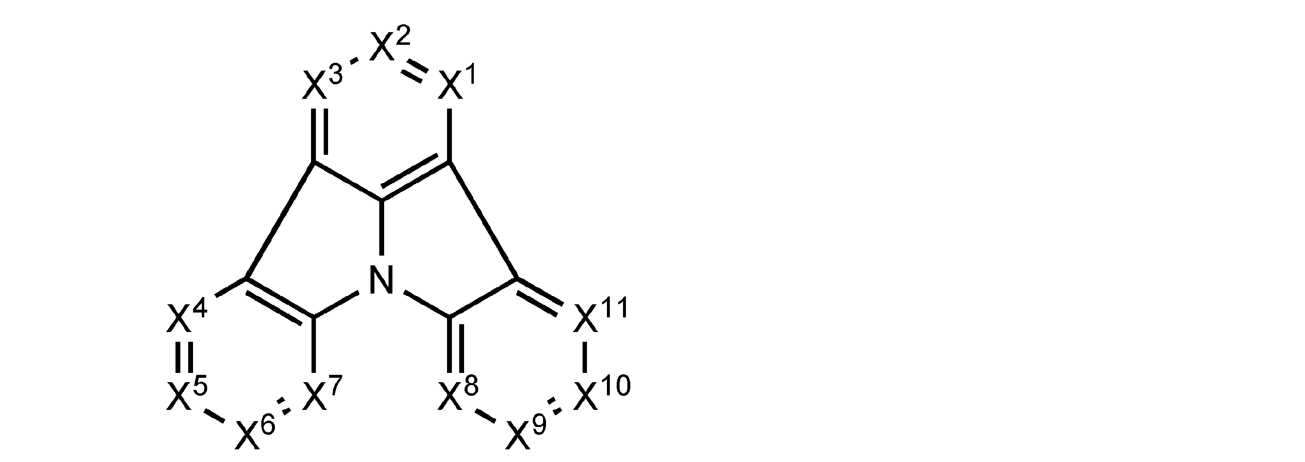
[2] [1]に記載の有機電界発光素子は、前記一般式(1)において、R0どうしが互いに結合して環を形成する前記隣接する2つのCR0の一方のR0が、6員環のアリール基またはヘテロアリール基を表すことが好ましい。
[3] [1]または[2]に記載の有機電界発光素子は、前記一般式(1)で表される化合物が、下記一般式(2)~(9)のいずれかで表される化合物であることが好ましい。


[4] [1]または[2]に記載の有機電界発光素子は、前記一般式(1)で表される化合物が、下記一般式(10)~(17)のいずれかで表される化合物であることが好ましい。
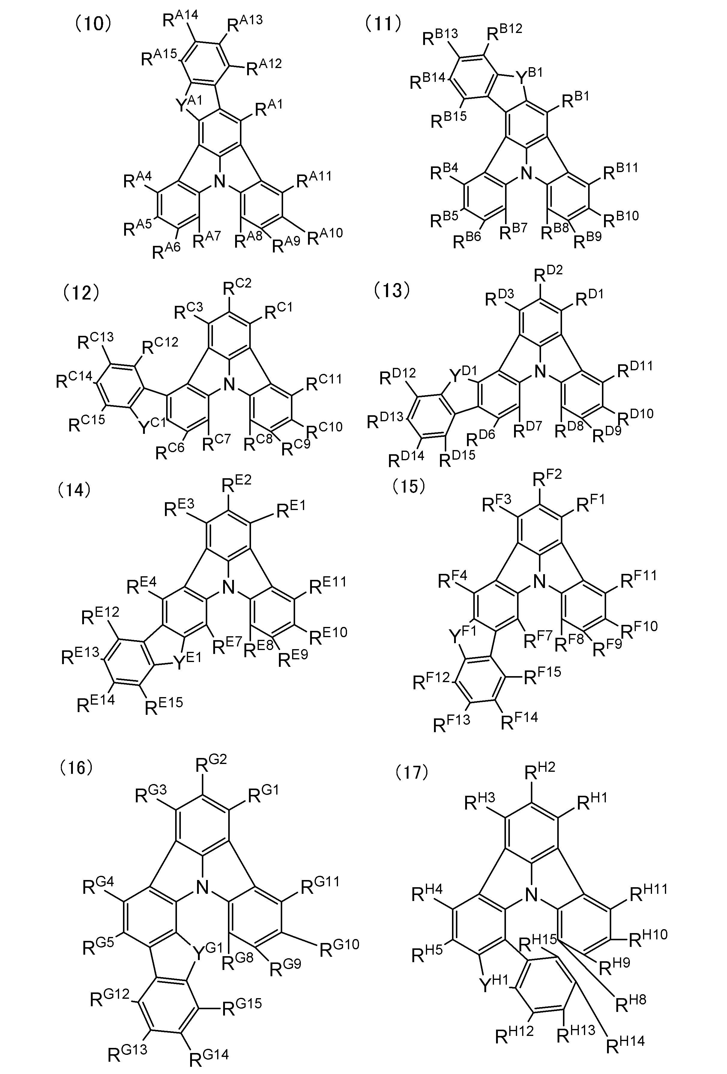
[5] [1]~[4]のいずれか一項に記載の有機電界発光素子は、前記一般式(1)で表される化合物のLUMOの値が、電子密度汎関数法(B3LYP/6-31G(d)レベル)で求めたとき、1.25よりも大きい化合物であることが好ましい。
[6] [1]~[5]のいずれか一項に記載の有機電界発光素子は、前記一般式(1)で表される化合物が、ピリジン環、ピリミジン環、トリアジン環、シアノ基およびカルボニル基のうち少なくとも1つを含む置換基を有する化合物であることが好ましい。
[7] [1]~[6]のいずれか一項に記載の有機電界発光素子は、前記発光層に燐光発光材料を少なくとも一種含むことが好ましい。
[8] [1]~[6]のいずれか一項に記載の有機電界発光素子は、前記燐光発光材料が、下記一般式(E-1)で表されるイリジウム錯体であることが好ましい。

A1はZ1と窒素原子と共に5又は6員のヘテロ環を形成する原子群を表す。
B1はZ2と炭素原子と共に5又は6員環を形成する原子群を表す。
(X-Y)はモノアニオン性の二座配位子を表す。
nE1は1~3の整数を表す。)
[9] [8]に記載の有機電界発光素子は、前記一般式(E-1)で表されるイリジウム錯体が下記一般式(E-2)で表されることが好ましい。
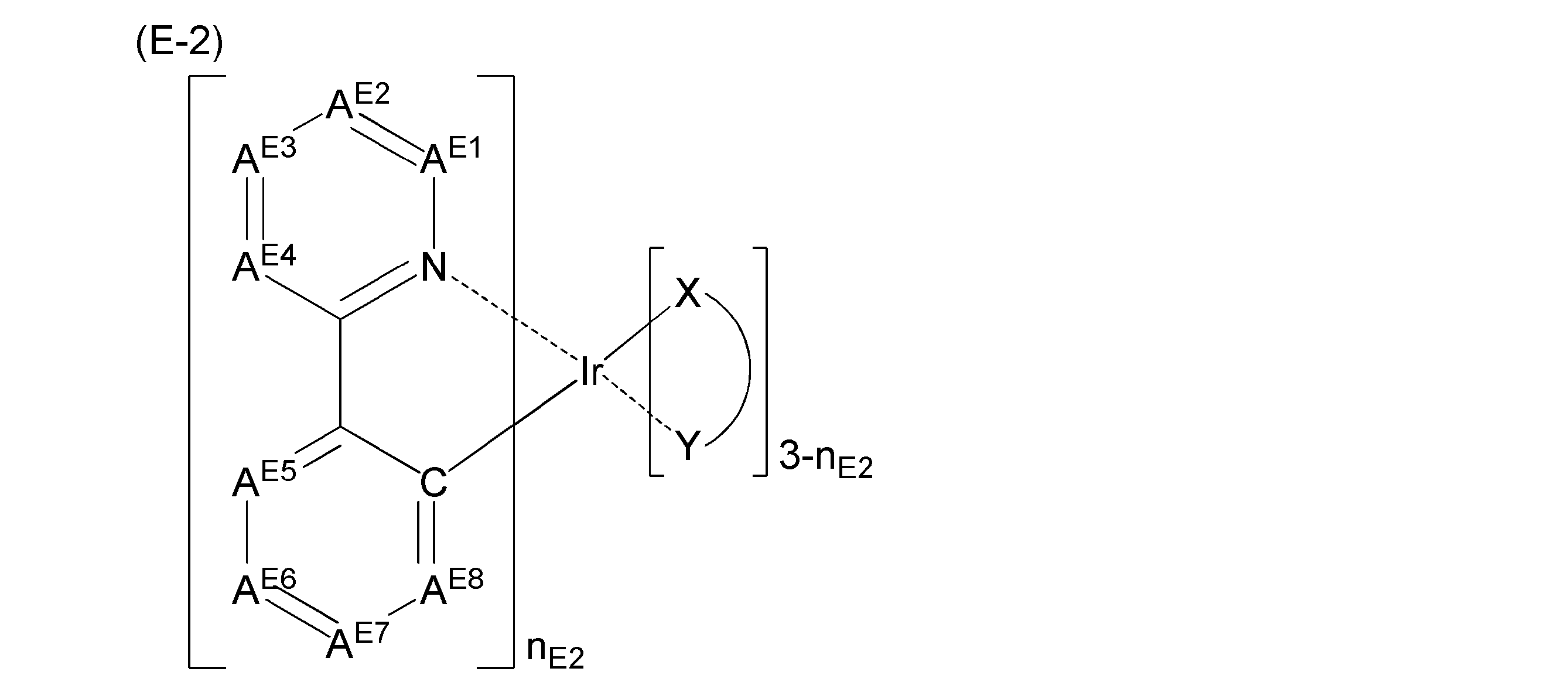
REは水素原子又は置換基を表す。
(X-Y)はモノアニオン性の二座配位子を表す。
nE2は1~3の整数を表す。)
[10] [1]~[9]のいずれか一項に記載の有機電界発光素子は、前記発光層が[1]~[6]のいずれかに記載の化合物を含有することが好ましい。
[11] [1]~[10]のいずれか一項に記載の有機電界発光素子を用いた発光装置。
[12] [1]~[10]のいずれか一項に記載の有機電界発光素子を用いた表示装置。
[13] [1]~[10]のいずれか一項に記載の有機電界発光素子を用いた照明装置。
[14] 下記一般式(1)で表される化合物。
一般式(1)

[15] [14]に記載の化合物は、下記一般式(2)~(9)のいずれかで表されることが好ましい。


[16] [14]または[15]に記載の化合物は、下記一般式(10)~(17)のいずれかで表されることが好ましい。

[17] 下記一般式(1)で表される有機電界発光素子用材料。
一般式(1)

[18] [17]に記載の有機電界発光素子用材料は、下記一般式(2)~(9)のいずれかで表されることが好ましい。

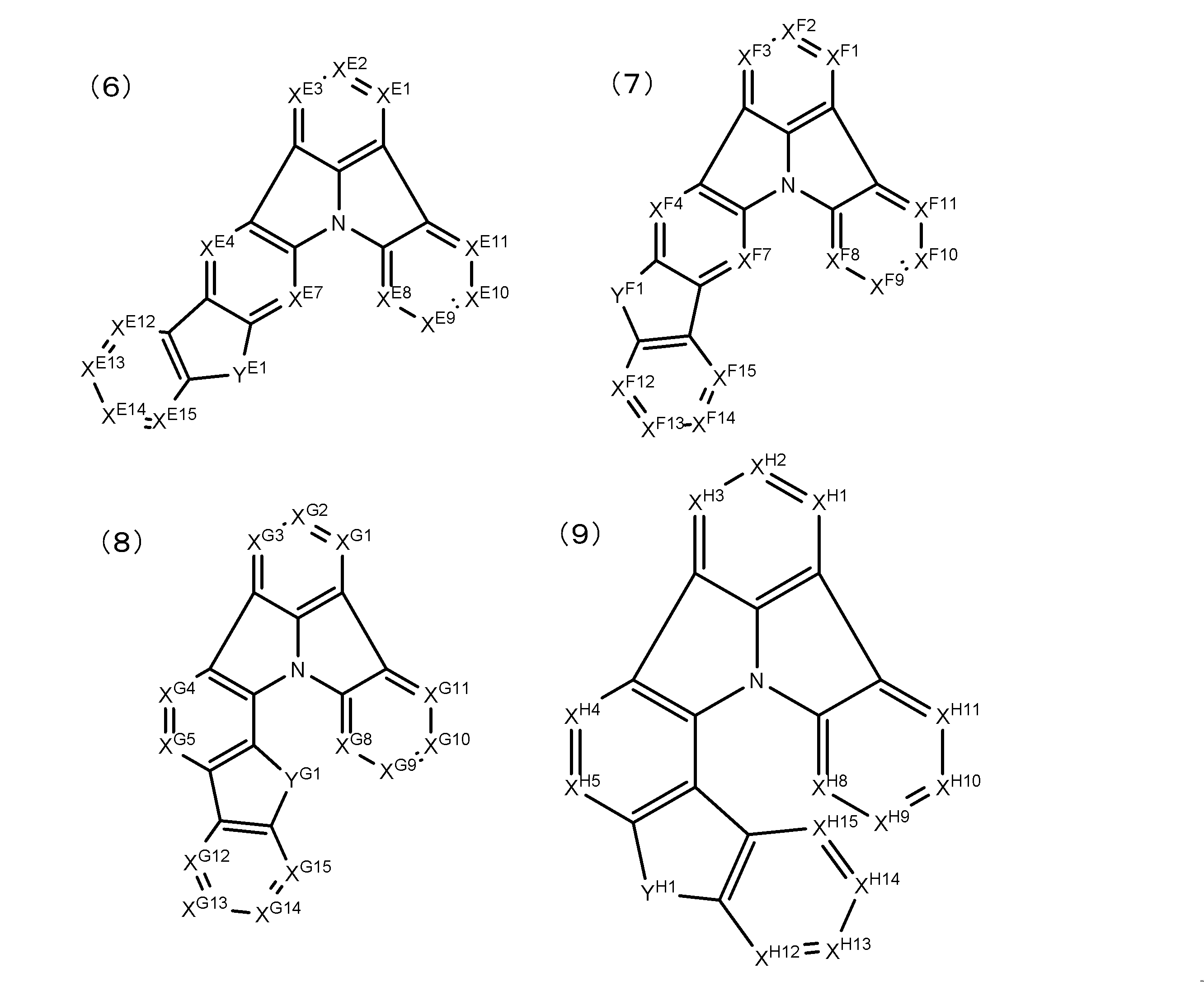
[19] [17]または[18]に記載の有機電界発光素子用材料は、下記一般式(10)~(17)のいずれかで表されることが好ましい。
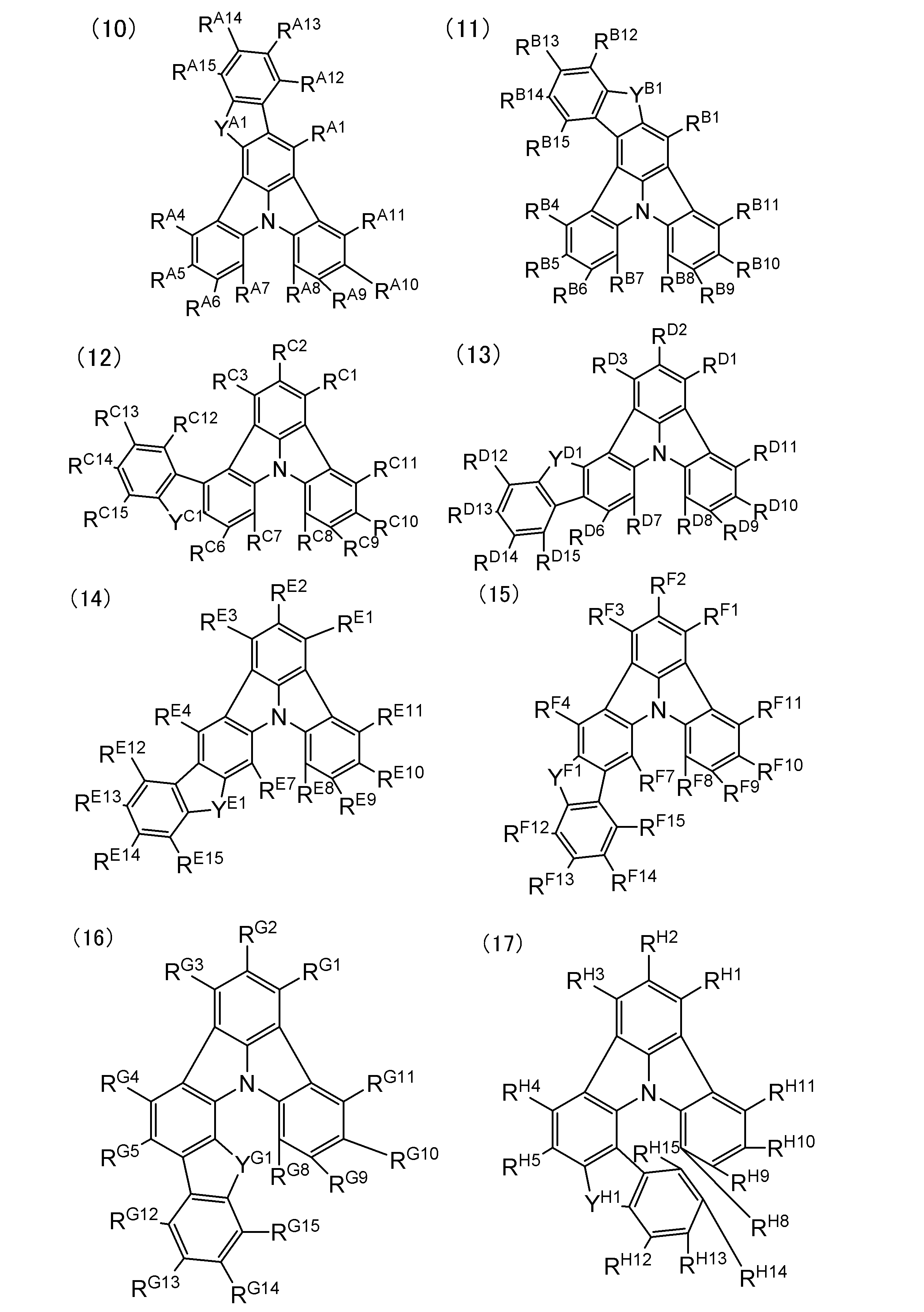
また、本発明によれば、更に、該有機電界発光素子を用いた発光装置、表示装置及び照明装置を提供することができる。
本発明の化合物および本発明の有機電界発光素子用材料は、前記一般式(1)で表されることを特徴とする。
本発明の有機電界発光素子は、基板と、該基板上に配置され、陽極及び陰極からなる一対の電極と、該電極間に配置され、発光層を含む少なくとも一層の有機層とを有し、前記有機層の少なくとも一層に前記一般式(1)で表される化合物を含むことを特徴とする。
有機電界発光素子の素子構成、基板、陰極及び陽極については、例えば、特開2008-270736号公報に詳述されており、該公報に記載の事項を本発明に適用することができる。
以下、本発明の有機電界発光素子の好ましい態様について、基板、電極、有機層、保護層、封止容器、駆動方法、発光波長、用途の順で詳細に説明する。
本発明の有機電界発光素子は、基板を有する。
本発明で使用する基板としては、有機層から発せられる光を散乱又は減衰させない基板であることが好ましい。有機材料の場合には、耐熱性、寸法安定性、耐溶剤性、電気絶縁性、及び加工性に優れていることが好ましい。
本発明の有機電界発光素子は、前記基板上に配置され、陽極及び陰極を含む一対の電極を有する。
発光素子の性質上、一対の電極である陽極及び陰極のうち少なくとも一方の電極は、透明若しくは半透明であることが好ましい。
陽極は、通常、有機層に正孔を供給する電極としての機能を有していればよく、その形状、構造、大きさ等については特に制限はなく、発光素子の用途、目的に応じて、公知の電極材料の中から適宜選択することができる。前述のごとく、陽極は、通常透明陽極として設けられる。
陰極は、通常、有機層に電子を注入する電極としての機能を有していればよく、その形状、構造、大きさ等については特に制限はなく、発光素子の用途、目的に応じて、公知の電極材料の中から適宜選択することができる。
本発明の有機電界発光素子は、前記電極間に配置された有機層を有し、前記有機層が、前記一般式(1)で表される化合物を含むことを特徴とする。
前記有機層は、特に制限はなく、有機電界発光素子の用途、目的に応じて適宜選択することができるが、前記透明電極上に又は前記半透明電極上に形成されるのが好ましい。この場合、有機層は、前記透明電極又は前記半透明電極上の全面又は一面に形成される。
有機層の形状、大きさ、及び厚み等については、特に制限はなく、目的に応じて適宜選択することができる。
以下、本発明の有機電界発光素子における、有機層の構成、有機層の形成方法、有機層を構成する各層の好ましい態様および各層に使用される材料について順に説明する。
本発明の有機電界発光素子では、前記有機層が、電荷輸送層を含むことが好ましい。前記電荷輸送層とは、有機電界発光素子に電圧を印加した際に電荷移動が起こる層をいう。具体的には正孔注入層、正孔輸送層、電子ブロック層、発光層、正孔ブロック層、電子輸送層又は電子注入層が挙げられる。
本発明の有機電界発光素子では、前記燐光発光材料を含む発光層とその他の有機層を有し、前記有機層が前記一般式(1)で表される化合物を含む。このとき、前記一般式(1)で表される化合物が含まれる場所に特に制限はないが、前記発光層が前記一般式(1)で表される化合物を含有することが好ましい。このとき、前記一般式(1)で表される化合物が、発光層のホスト化合物として用いられることが好ましい。さらに、本発明の有機電界発光素子では、前記有機層が、前記燐光発光材料を含む発光層とその他の有機層を有すことがより好ましい。但し、本発明の有機電界発光素子は、前記有機層が発光層とその他の有機層を有する場合であっても、必ずしも明確に層間が区別されなくてもよい。
これらの有機層は、それぞれ複数層設けてもよく、複数層設ける場合には同一の材料で形成してもよいし、層毎に異なる材料で形成してもよい。
本発明の有機電界発光素子において、各有機層は、蒸着法やスパッタ法等の乾式製膜法、転写法、印刷法、スピンコート法、バーコート法等の湿式製膜法(溶液塗布法)のいずれによっても好適に形成することができる。
本発明の有機電界発光素子は、前記一対の電極間に配置された有機層が、少なくとも一層の前記一般式(1)で表される化合物を含む組成物の蒸着により形成された層を含むことが好ましい。
前記発光層は、電界印加時に、陽極、正孔注入層又は正孔輸送層から正孔を受け取り、陰極、電子注入層又は電子輸送層から電子を受け取り、正孔と電子の再結合の場を提供して発光させる機能を有する層である。但し、本発明における前記発光層は、このようなメカニズムによる発光に必ずしも限定されるものではない。本発明の有機電界発光素子における発光層は、少なくとも一種の燐光発光材料を含有することが好ましい。
以下、前記発光層の材料として、前記一般式(1)で表される化合物、前記燐光発光材料、前記一般式(1)で表される化合物以外のその他のホスト材料について順に説明する。なお、前記一般式(1)で表される化合物は、本発明の有機電界発光素子において前記発光層以外に用いられてもよい。
WO2010/131855号公報などに記載のフェニルカルバゾールは、カルバゾールのNとフェニル基のCの間の結合が切れることが劣化素子後の分解物解析の結果、報告されている(J.Appl.Phys. 2007, 101, 024512)。これに対し、下記一般式(1)で表されるインドロカルバゾール骨格またはインドロカルバゾール骨格の炭素原子の特定の位置を窒素原子に置換した骨格を有する化合物は、得られる有機電界発光素子の耐久性を高めることができる。いかなる理由に拘泥するものでもないが、本発明者らは、上記の論文から示唆されるように、耐久性を悪化させる原因は上記の結合開裂にあると考えており、結合開裂の抑制または結合開裂後の再結合の促進により、下記一般式(1)で表されるインドロカルバゾール骨格またはインドロカルバゾール骨格の炭素原子の特定の位置を窒素原子に置換した骨格を有する化合物は耐久性が高いと考えられる。
ここで、従来よく知られていたインドロカルバゾール系化合物は、インドロカルバゾールにさらなる縮合環を有していなかった。このようなインドロカルバゾール系化合物はイオン化ポテンシャルが大きく(=HOMOの値が大きく)、ホール輸送層からのホール注入障壁が高く、実用レベルの素子駆動電圧までには至っていない。本発明では、インドロカルバゾール骨格を有する化合物または、インドロカルバゾール骨格の炭素原子の特定の位置を窒素原子に置換した骨格を有する化合物について、π平面を縮環させることで、素子駆動電圧が縮合環を有していないインドロカルバゾールに比べ低下させることができる。いかなる理由に拘泥するものでもないが、イオン化ポテンシャルを小さく(=HOMOの値が小さく)することができ、その結果、ホール輸送層からのホール注入障壁が緩和されたためと考えられる。
また、WO2011/042107号公報や特開2010-087496号公報に記載のインドロカルバゾール骨格を有する化合物は、インドロカルバゾール骨格がさらに縮環されることに言及しているが、具体的化合物の例示は一切なく、また、骨格を構成する環員数や、縮環の位置に問題があるため、耐久性と駆動電圧の低減の両立が困難であることがわかった。
以下、下記一般式(1)で表される化合物について説明する。

なお、本発明において、前記一般式(1)の説明における水素原子は同位体(重水素原子等)も含み、また更に置換基を構成する原子は、その同位体も含んでいることを表す。
本発明において、「置換基」というとき、その置換基は置換されていてもよい。例えば、本発明で「アルキル基」と言う時、フッ素原子で置換されたアルキル基(例えばトリフルオロメチル基)やアリール基で置換されたアルキル基(例えばトリフェニルメチル基)なども含むが、「炭素数1~6のアルキル基」と言うとき、置換されたものも含めた全ての基として炭素数が1~6であることを示す。
アルキル基(好ましくは炭素数1~30、より好ましくは炭素数1~20、特に好ましくは炭素数1~10であり、例えばメチル、エチル、n-プロピル、イソプロピル、t-ブチル、n-ヘキシル、n-オクチル、n-デシル、n-ヘキサデシル、シクロプロピル、シクロペンチル、シクロヘキシルなどが挙げられる。)、アルケニル基(好ましくは炭素数2~30、より好ましくは炭素数2~20、特に好ましくは炭素数2~10であり、例えばビニル、アリル、2-ブテニル、3-ペンテニルなどが挙げられる。)、アルキニル基(好ましくは炭素数2~30、より好ましくは炭素数2~20、特に好ましくは炭素数2~10であり、例えばプロパルギル、3-ペンチニルなどが挙げられる。)、アリール基(好ましくは炭素数6~30、より好ましくは炭素数6~20、特に好ましくは炭素数6~14であり、例えばフェニル、p-メチルフェニル、ナフチル、アントラニルなどが挙げられる。)、アミノ基(好ましくは炭素数0~30、より好ましくは炭素数0~20、特に好ましくは炭素数0~10であり、例えばアミノ、メチルアミノ、ジメチルアミノ、ジエチルアミノ、ジベンジルアミノ、フェニルアミノ、ジフェニルアミノ、ジトリルアミノなどが挙げられる。)、アルコキシ基(好ましくは炭素数1~30、より好ましくは炭素数1~20、特に好ましくは炭素数1~10であり、例えばメトキシ、エトキシ、ブトキシ、2-エチルヘキシロキシなどが挙げられる。)、アリールオキシ基(好ましくは炭素数6~30、より好ましくは炭素数6~20、特に好ましくは炭素数6~12であり、例えばフェニルオキシ、1-ナフチルオキシ、2-ナフチルオキシなどが挙げられる。)、ヘテロ環オキシ基(好ましくは炭素数1~30、より好ましくは炭素数1~20、特に好ましくは炭素数1~12であり、例えばピリジルオキシ、ピラジルオキシ、ピリミジルオキシ、キノリルオキシなどが挙げられる。)、アシル基(好ましくは炭素数2~30、より好ましくは炭素数2~20、特に好ましくは炭素数2~12であり、例えばアセチル、ベンゾイル、ホルミル、ピバロイルなどが挙げられる。)、アルコキシカルボニル基(好ましくは炭素数2~30、より好ましくは炭素数2~20、特に好ましくは炭素数2~12であり、例えばメトキシカルボニル、エトキシカルボニルなどが挙げられる。)、アリールオキシカルボニル基(好ましくは炭素数7~30、より好ましくは炭素数7~20、特に好ましくは炭素数7~12であり、例えばフェニルオキシカルボニルなどが挙げられる。)、アシルオキシ基(好ましくは炭素数2~30、より好ましくは炭素数2~20、特に好ましくは炭素数2~10であり、例えばアセトキシ、ベンゾイルオキシなどが挙げられる。)、アシルアミノ基(好ましくは炭素数2~30、より好ましくは炭素数2~20、特に好ましくは炭素数2~10であり、例えばアセチルアミノ、ベンゾイルアミノなどが挙げられる。)、アルコキシカルボニルアミノ基(好ましくは炭素数2~30、より好ましくは炭素数2~20、特に好ましくは炭素数2~12であり、例えばメトキシカルボニルアミノなどが挙げられる。)、アリールオキシカルボニルアミノ基(好ましくは炭素数7~30、より好ましくは炭素数7~20、特に好ましくは炭素数7~12であり、例えばフェニルオキシカルボニルアミノなどが挙げられる。)、スルホニルアミノ基(好ましくは炭素数1~30、より好ましくは炭素数1~20、特に好ましくは炭素数1~12であり、例えばメタンスルホニルアミノ、ベンゼンスルホニルアミノなどが挙げられる。)、スルファモイル基(好ましくは炭素数0~30、より好ましくは炭素数0~20、特に好ましくは炭素数0~12であり、例えばスルファモイル、メチルスルファモイル、ジメチルスルファモイル、フェニルスルファモイルなどが挙げられる。)、カルバモイル基(好ましくは炭素数1~30、より好ましくは炭素数1~20、特に好ましくは炭素数1~12であり、例えばカルバモイル、メチルカルバモイル、ジエチルカルバモイル、フェニルカルバモイルなどが挙げられる。)、アルキルチオ基(好ましくは炭素数1~30、より好ましくは炭素数1~20、特に好ましくは炭素数1~12であり、例えばメチルチオ、エチルチオなどが挙げられる。)、アリールチオ基(好ましくは炭素数6~30、より好ましくは炭素数6~20、特に好ましくは炭素数6~12であり、例えばフェニルチオなどが挙げられる。)、ヘテロ環チオ基(好ましくは炭素数1~30、より好ましくは炭素数1~20、特に好ましくは炭素数1~12であり、例えばピリジルチオ、2-ベンズイミゾリルチオ、2-ベンズオキサゾリルチオ、2-ベンズチアゾリルチオなどが挙げられる。)、スルホニル基(好ましくは炭素数1~30、より好ましくは炭素数1~20、特に好ましくは炭素数1~12であり、例えばメシル、トシルなどが挙げられる。)、スルフィニル基(好ましくは炭素数1~30、より好ましくは炭素数1~20、特に好ましくは炭素数1~12であり、例えばメタンスルフィニル、ベンゼンスルフィニルなどが挙げられる。)、ウレイド基(好ましくは炭素数1~30、より好ましくは炭素数1~20、特に好ましくは炭素数1~12であり、例えばウレイド、メチルウレイド、フェニルウレイドなどが挙げられる。)、リン酸アミド基(好ましくは炭素数1~30、より好ましくは炭素数1~20、特に好ましくは炭素数1~12であり、例えばジエチルリン酸アミド、フェニルリン酸アミドなどが挙げられる。)、ヒドロキシ基、メルカプト基、ハロゲン原子(例えばフッ素原子、塩素原子、臭素原子、ヨウ素原子)、スルホ基、カルボキシル基、ニトロ基、ヒドロキサム酸基、スルフィノ基、ヒドラジノ基、イミノ基、ヘテロ環基(芳香族ヘテロ環基も包含し、好ましくは炭素数1~30、より好ましくは炭素数1~12であり、ヘテロ原子としては、例えば窒素原子、酸素原子、硫黄原子、リン原子、ケイ素原子、セレン原子、テルル原子であり、具体的にはピリジル、ピラジニル、ピリミジル、ピリダジニル、ピロリル、ピラゾリル、トリアゾリル、イミダゾリル、オキサゾリル、チアゾリル、イソキサゾリル、イソチアゾリル、キノリル、フリル、チエニル、セレノフェニル、テルロフェニル、ピペリジル、ピペリジノ、モルホリノ、ピロリジル、ピロリジノ、ベンゾオキサゾリル、ベンゾイミダゾリル、ベンゾチアゾリル、カルバゾリル基、アゼピニル基、シロリル基などが挙げられる。)、シリル基(好ましくは炭素数3~40、より好ましくは炭素数3~30、特に好ましくは炭素数3~24であり、例えばトリメチルシリル、トリフェニルシリルなどが挙げられる。)、シリルオキシ基(好ましくは炭素数3~40、より好ましくは炭素数3~30、特に好ましくは炭素数3~24であり、例えばトリメチルシリルオキシ、トリフェニルシリルオキシなどが挙げられる。)、ホスホリル基(例えばジフェニルホスホリル基、ジメチルホスホリル基などが挙げられる。)が挙げられる。これらの置換基は更に置換されてもよく、更なる置換基としては、以上に説明した置換基群Aから選択される基を挙げることができる。
R0が表すヘテロアリール基は、好ましくは環員数5~30、より好ましくは環員数5~20、特に好ましくは環員数5~15であり、例えばピリジル基、ピリミジル基、トリアジル基、ピラジル基、ピリダジル基、カルバゾリル基、ジベンゾチオフェニル基、ジベンゾフラニル基などが挙げられる。
但し、前記R0が有していてもよいさらなる置換基どうしは、互いに連結して縮環を形成しないことが、緑燐光の発光効率を高める観点から好ましい。
前記R0が有していてもよいさらなる置換基は、またさらに置換されていてもよい。前記R0が有していてもよいさらなる置換基が、ピリジニル基、ピリミジニル基またはトリアジニル基である場合はいずれもジアリール置換(ジフェニル置換であることが好ましい)であることが好ましい。
このようなアリール基またはヘテロアリール基を表すR0と結合して形成される縮合環が5員環となる置換基としては、縮合環を形成したときの原子連結鎖長が1の連結基としてCR1R2、NR3(R1~R3はそれぞれ独立に置換基を表す)、O、SまたはSeを形成できる置換基が好ましく、CR1R2、NR3、OまたはSを形成できる置換基がより好ましく、OまたはSを形成できる置換基が特に好ましく、Oを形成できる置換基がより特に好ましい。
また、X1~X11のうちR0が置換基であるCR0の個数は、R0どうしが互いに結合して環を形成するR0を含めて、2~11個であり、3~8個であることが好ましく、3または4個であることがより好ましい。


XA1~XA15、XB1~XB15、XC1~XC15、XD1~XD15、XE1~XE15、XF1~XF15、XG1~XG15およびXH1~XH15はそれぞれ独立にCR4またはNを表し、CR4はそれぞれ独立に水素原子または置換基を表す。
前記炭素原子上の置換基R1およびR2が表す置換基としては、前述の置換基群Aを挙げることができ、炭素原子上の置換基として好ましくはアルキル基、ペルフルオロアルキル基、アリール基、ヘテロアリール基、ジアルキルアミノ基、ジアリールアミノ基、アルコキシ基、シアノ基、フッ素原子であり、アルキル基またはアリール基がより好ましく、メチル基またはフェニル基が特に好ましい。
前記窒素原子上の置換基R3が表す置換基としては、以下の置換基群Bを挙げることができる。
《置換基群B》
アルキル基(好ましくは炭素数1~30、より好ましくは炭素数1~20、特に好ましくは炭素数1~10であり、例えばメチル、エチル、イソプロピル、tert-ブチル、n-オクチル、n-デシル、n-ヘキサデシル、シクロプロピル、シクロペンチル、シクロヘキシルなどが挙げられる。)、アルケニル基(好ましくは炭素数2~30、より好ましくは炭素数2~20、特に好ましくは炭素数2~10であり、例えばビニル、アリル、2-ブテニル、3-ペンテニルなどが挙げられる。)、アルキニル基(好ましくは炭素数2~30、より好ましくは炭素数2~20、特に好ましくは炭素数2~10であり、例えばプロパルギル、3-ペンチニルなどが挙げられる。)、アリール基(好ましくは炭素数6~30、より好ましくは炭素数6~20、特に好ましくは炭素数6~12であり、例えばフェニル、p-メチルフェニル、ナフチル、アントラニルなどが挙げられる。)、シアノ基、ヘテロ環基(芳香族ヘテロ環基も包含し、好ましくは炭素数1~30、より好ましくは炭素数1~12であり、ヘテロ原子としては、例えば窒素原子、酸素原子、硫黄原子、リン原子、ケイ素原子、セレン原子、テルル原子であり、具体的にはピリジル、ピラジニル、ピリミジル、ピリダジニル、ピロリル、ピラゾリル、トリアゾリル、イミダゾリル、オキサゾリル、チアゾリル、イソキサゾリル、イソチアゾリル、キノリル、フリル、チエニル、セレノフェニル、テルロフェニル、ピペリジル、ピペリジノ、モルホリノ、ピロリジル、ピロリジノ、ベンゾオキサゾリル、ベンゾイミダゾリル、ベンゾチアゾリル、カルバゾリル基、アゼピニル基、シロリル基などが挙げられる。)などが挙げられる。これらの置換基は更に置換されてもよく、更なる置換基としては、以上に説明した置換基群Bから選択される基を挙げることができる。
R3が表す窒素原子上の置換基として好ましくは、アルキル基、アリール基、芳香族ヘテロ環基であり、アリール基がより好ましく、フェニル基またはフェニル基で置換されたフェニル基(ビフェニル基)が特に好ましい。
また、YA1のR3が表す窒素原子上の置換基とXA15が連結して環を形成してもよい。
XA1~XA11の好ましい範囲は、前記一般式(1)におけるX1~X11の好ましい範囲と同様である。
R4が表すヘテロアリール基は、好ましくは環員数5~30、より好ましくは環員数5~20、特に好ましくは環員数5~15であり、例えばピリジル基、ピリミジル基、トリアジル基、ピラジル基、ピリダジル基、カルバゾリル基、ジベンゾチオフェニル基、ジベンゾフラニル基などが挙げられる。
また、XA12~XA15のうちR4が置換基であるCR4の個数は、0または1個であることが好ましく、0個であることがより好ましい。
また、YB1のR3が表す窒素原子上の置換基とXB1またはXB12が連結して環を形成してもよい。
前記一般式(3)中、XB1~XB15はそれぞれ独立にCR4またはNを表し、CR4はそれぞれ独立に水素原子または置換基を表す。XB1~XB15の好ましい範囲は、前記一般式(2)におけるXA1~XA15の好ましい範囲と同様である。
前記一般式(3)におけるYB1とXB1~XB15の好ましい関係は、前記一般式(2)におけるYA1とXA1~XA15の好ましい関係と同様であり、すなわちXB12~XB15が置換基であるCR4を有する場合のCR4の位置は、YB1に隣接する位置(前記一般式(3)においては、XB12の位置)であることが好ましい。
前記一般式(3)は後述の一般式(11)で表されることがより好ましい。
また、YC1のR3が表す窒素原子上の置換基とXC6またはXC15が連結して環を形成してもよい。
前記一般式(4)中、XC1~XC15はそれぞれ独立にCR4またはNを表し、CR4はそれぞれ独立に水素原子または置換基を表す。XC1~XC15の好ましい範囲は、前記一般式(2)におけるXA1~XA15の好ましい範囲と同様である。
前記一般式(4)におけるYC1とXC1~XC15の好ましい関係は、前記一般式(2)におけるYA1とXA1~XA15の好ましい関係と同様であり、すなわちXC12~XC15が置換基であるCR4を有する場合のCR4の位置は、YC1に隣接する位置(前記一般式(4)においては、XC15の位置)であることが好ましい。
前記一般式(4)は後述の一般式(12)で表されることがより好ましい。
また、YD1のR3が表す窒素原子上の置換基とXD12が連結して環を形成してもよい。
前記一般式(5)中、XD1~XD15はそれぞれ独立にCR4またはNを表し、CR4はそれぞれ独立に水素原子または置換基を表す。XD1~XD15の好ましい範囲は、前記一般式(2)におけるXA1~XA15の好ましい範囲と同様である。
前記一般式(5)におけるYD1とXD1~XD15の好ましい関係は、前記一般式(2)におけるYA1とXA1~XA15の好ましい関係と同様であり、すなわちXD12~XD15が置換基であるCR4を有する場合のCR4の位置は、YD1に隣接する位置(前記一般式(5)においては、XD12の位置)であることが好ましい。
前記一般式(5)は後述の一般式(13)で表されることがより好ましい。
また、YE1のR3が表す窒素原子上の置換基とXE7またはXE15が連結して環を形成してもよい。
前記一般式(6)中、XE1~XE15はそれぞれ独立にCR4またはNを表し、CR4はそれぞれ独立に水素原子または置換基を表す。XE1~XE15の好ましい範囲は、前記一般式(2)におけるXA1~XA15の好ましい範囲と同様である。
前記一般式(6)におけるYE1とXE1~XE15の好ましい関係は、前記一般式(2)におけるYA1とXA1~XA15の好ましい関係と同様であり、すなわちXE12~XE15が置換基であるCR4を有する場合のCR4の位置は、YE1に隣接する位置(前記一般式(6)においては、XE15の位置)であることが好ましい。
前記一般式(6)は後述の一般式(14)で表されることがより好ましい。
また、YF1のR3が表す窒素原子上の置換基とXF4またはXE12が連結して環を形成してもよい。
前記一般式(7)中、XF1~XF15はそれぞれ独立にCR4またはNを表し、CR4はそれぞれ独立に水素原子または置換基を表す。XF1~XF15の好ましい範囲は、前記一般式(2)におけるXA1~XA15の好ましい範囲と同様である。
前記一般式(7)におけるYF1とXF1~XF15の好ましい関係は、前記一般式(2)におけるYA1とXA1~XA15の好ましい関係と同様であり、すなわちXF12~XF15が置換基であるCR4を有する場合のCR4の位置は、YF1に隣接する位置(前記一般式(7)においては、XF12の位置)であることが好ましい。
前記一般式(7)は後述の一般式(15)で表されることがより好ましい。
また、YG1のR3が表す窒素原子上の置換基とXG15が連結して環を形成してもよい。
前記一般式(8)中、XG1~XG15はそれぞれ独立にCR4またはNを表し、CR4はそれぞれ独立に水素原子または置換基を表す。XG1~XG15の好ましい範囲は、前記一般式(2)におけるXA1~XA15の好ましい範囲と同様である。
前記一般式(8)におけるYG1とXG1~XG15の好ましい関係は、前記一般式(2)におけるYA1とXA1~XA15の好ましい関係と同様であり、すなわちXG12~XG15が置換基であるCR4を有する場合のCR4の位置は、YG1に隣接する位置(前記一般式(8)においては、XG15の位置)であることが好ましい。
前記一般式(8)は後述の一般式(16)で表されることがより好ましい。
また、YH1のR3が表す窒素原子上の置換基とXH5またはXH12が連結して環を形成してもよい。
前記一般式(9)中、XH1~XH15はそれぞれ独立にCR4またはNを表し、CR4はそれぞれ独立に水素原子または置換基を表す。XH1~XH15の好ましい範囲は、前記一般式(2)におけるXA1~XA15の好ましい範囲と同様である。
前記一般式(9)におけるYH1とXH1~XH15の好ましい関係は、前記一般式(2)におけるYA1とXA1~XA15の好ましい関係と同様であり、すなわちXH12~XH15が置換基であるCR4を有する場合のCR4の位置は、YH1に隣接する位置(前記一般式(9)においては、XH12の位置)であることが好ましい。
前記一般式(9)は後述の一般式(17)で表されることがより好ましい。

また、YA1のR3が表す窒素原子上の置換基とRA15が連結して環を形成してもよい。
前記一般式(10)中、RA1~RA15はそれぞれ独立に水素原子または置換基を表し、RA1~RA15の好ましい範囲は、前記一般式(2)におけるXA1~XA15がすべてCR4を表す場合において各XA1~XA15が有するR4の好ましい範囲と同様である。
前記一般式(10)におけるYA1とRA1~RA15の好ましい関係は、前記一般式(2)におけるYA1と、前記一般式(2)におけるXA1~XA15がすべてCR4を表す場合において各XA1~XA15が有するR4との好ましい関係と同様であり、すなわちRA12~RA15が置換基を有する場合の置換基の位置は、YA1に隣接する位置(前記一般式(10)においては、RA15の位置)であることが好ましい。
また、YB1のR3が表す窒素原子上の置換基とRB1またはRB12が連結して環を形成してもよい。
前記一般式(11)中、RB1~RB15はそれぞれ独立に水素原子または置換基を表し、RB1~RB15の好ましい範囲は、前記一般式(3)におけるXB1~XB15がすべてCR4を表す場合において各XB1~XB15が有するR4の好ましい範囲と同様である。
前記一般式(11)におけるYB1とRB1~RB15の好ましい関係は、前記一般式(2)におけるYB1と、前記一般式(2)におけるXB1~XB15がすべてCR4を表す場合において各XB1~XB15が有するR4との好ましい関係と同様であり、すなわちRB12~RB15が置換基を有する場合の置換基の位置は、YB1に隣接する位置(前記一般式(11)においては、RB12の位置)であることが好ましい。
また、YC1のR3が表す窒素原子上の置換基とRC6またはRC15が連結して環を形成してもよい。
前記一般式(12)中、RC1~RC15はそれぞれ独立に水素原子または置換基を表し、RC1~RC15の好ましい範囲は、前記一般式(4)におけるXC1~XC15がすべてCR4を表す場合において各XC1~XC15が有するR4の好ましい範囲と同様である。
前記一般式(12)におけるYC1とRC1~RC15の好ましい関係は、前記一般式(4)におけるYC1と、前記一般式(4)におけるXC1~XC15がすべてCR4を表す場合において各XC1~XC15が有するR4との好ましい関係と同様であり、すなわちRC12~RC15が置換基を有する場合の置換基の位置は、YC1に隣接する位置(前記一般式(12)においては、RC15の位置)であることが好ましい。
また、YD1のR3が表す窒素原子上の置換基とRD12が連結して環を形成してもよい。
前記一般式(13)中、RD1~RD15はそれぞれ独立に水素原子または置換基を表し、RD1~RD15の好ましい範囲は、前記一般式(5)におけるXD1~XD15がすべてCR4を表す場合において各XD1~XD15が有するR4の好ましい範囲と同様である。
前記一般式(13)におけるYD1とRD1~RD15の好ましい関係は、前記一般式(2)におけるYD1と、前記一般式(5)におけるXD1~XD15がすべてCR4を表す場合において各XD1~XD15が有するR4との好ましい関係と同様であり、すなわちRD12~RD15が置換基を有する場合の置換基の位置は、YD1に隣接する位置(前記一般式(13)においては、RD12の位置)であることが好ましい。
また、YE1のR3が表す窒素原子上の置換基とRE7またはRE15が連結して環を形成してもよい。
前記一般式(14)中、RE1~RE15はそれぞれ独立に水素原子または置換基を表し、RE1~RE15の好ましい範囲は、前記一般式(6)におけるXE1~XE15がすべてCR4を表す場合において各XE1~XE15が有するR4の好ましい範囲と同様である。
前記一般式(14)におけるYE1とRE1~RE15の好ましい関係は、前記一般式(6)におけるYE1と、前記一般式(6)におけるXE1~XE15がすべてCR4を表す場合において各XE1~XE15が有するR4との好ましい関係と同様であり、すなわちRE12~RE15が置換基を有する場合の置換基の位置は、YE1に隣接する位置(前記一般式(14)においては、RE15の位置)であることが好ましい。
また、YF1のR3が表す窒素原子上の置換基とRF4またはRE12が連結して環を形成してもよい。
前記一般式(15)中、RF1~RF15はそれぞれ独立に水素原子または置換基を表し、RF1~RF15の好ましい範囲は、前記一般式(7)におけるXF1~XF15がすべてCR4を表す場合において各XF1~XF15が有するR4の好ましい範囲と同様である。
前記一般式(15)におけるYF1とRF1~RF15の好ましい関係は、前記一般式(7)におけるYF1と、前記一般式(7)におけるXF1~XF15がすべてCR4を表す場合において各XF1~XF15が有するR4との好ましい関係と同様であり、すなわちRF12~RF15が置換基を有する場合の置換基の位置は、YF1に隣接する位置(前記一般式(15)においては、RF12の位置)であることが好ましい。
また、YG1のR3が表す窒素原子上の置換基とXG15が連結して環を形成してもよい。
前記一般式(16)中、RG1~RG15はそれぞれ独立に水素原子または置換基を表し、RG1~RG15の好ましい範囲は、前記一般式(8)におけるXG1~XG15がすべてCR4を表す場合において各XG1~XG15が有するR4の好ましい範囲と同様である。
前記一般式(16)におけるYG1とRG1~RG15の好ましい関係は、前記一般式(8)におけるYG1と、前記一般式(8)におけるXG1~XG15がすべてCR4を表す場合において各XG1~XG15が有するR4との好ましい関係と同様であり、すなわちRG12~RG15が置換基を有する場合の置換基の位置は、YG1に隣接する位置(前記一般式(16)においては、RG15の位置)であることが好ましい。
また、YH1のR3が表す窒素原子上の置換基とRH5またはRH12が連結して環を形成してもよい。
前記一般式(17)中、RH1~RH15はそれぞれ独立に水素原子または置換基を表し、RH1~RH15の好ましい範囲は、前記一般式(9)におけるXH1~XH15がすべてCR4を表す場合において各XH1~XH15が有するR4の好ましい範囲と同様である。
前記一般式(17)におけるYH1とRH1~RH15の好ましい関係は、前記一般式(9)におけるYH1と、前記一般式(9)におけるXH1~XH15がすべてCR4を表す場合において各XH1~XH15が有するR4との好ましい関係と同様であり、すなわちRH12~RH15が置換基を有する場合の置換基の位置は、YH1に隣接する位置(前記一般式(17)においては、RH12の位置)であることが好ましい。
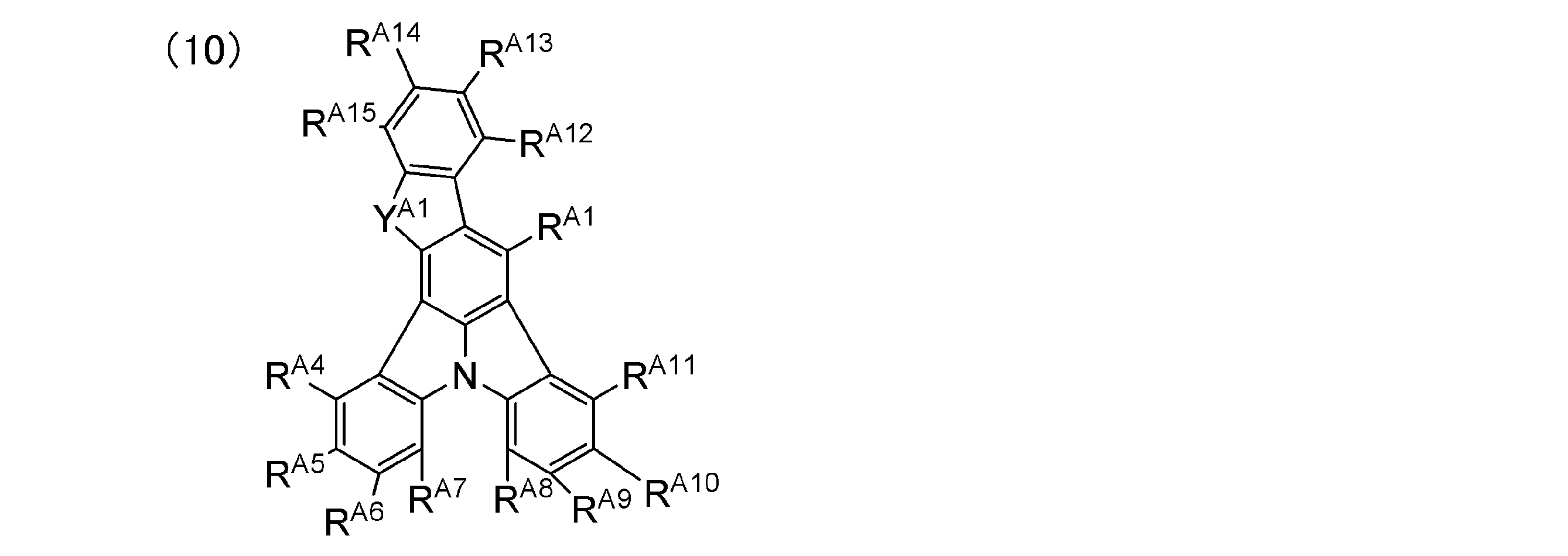

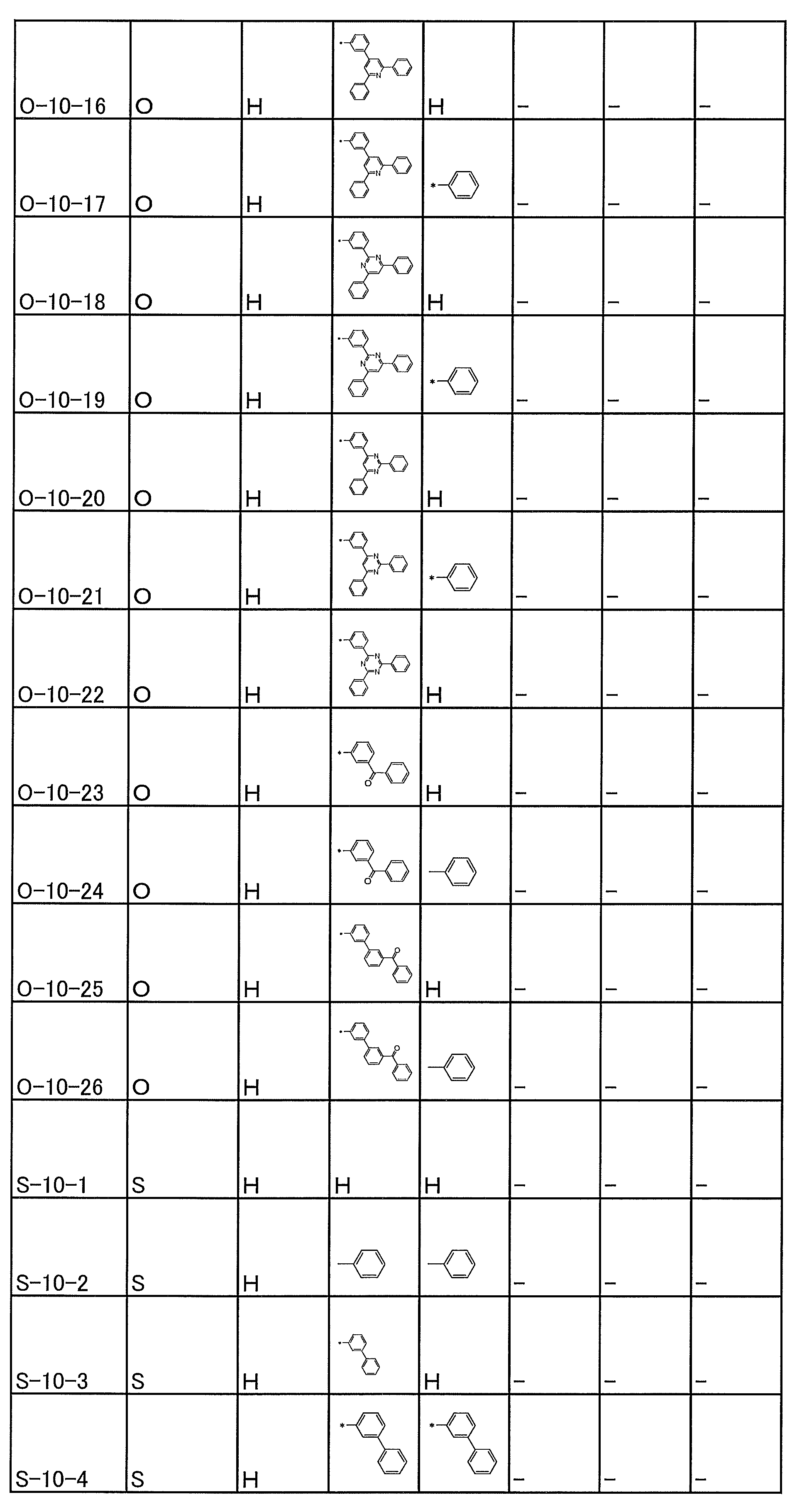


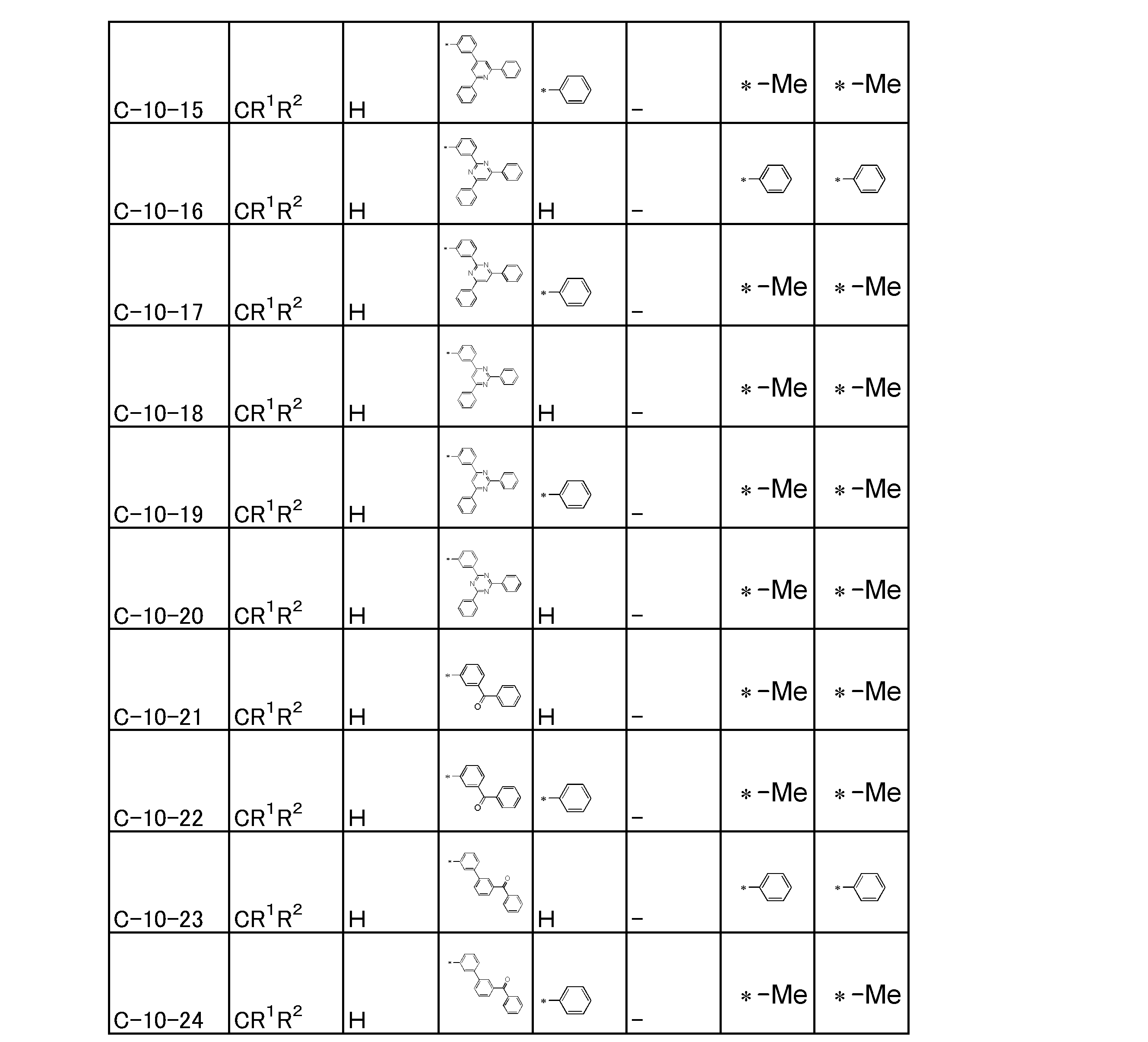

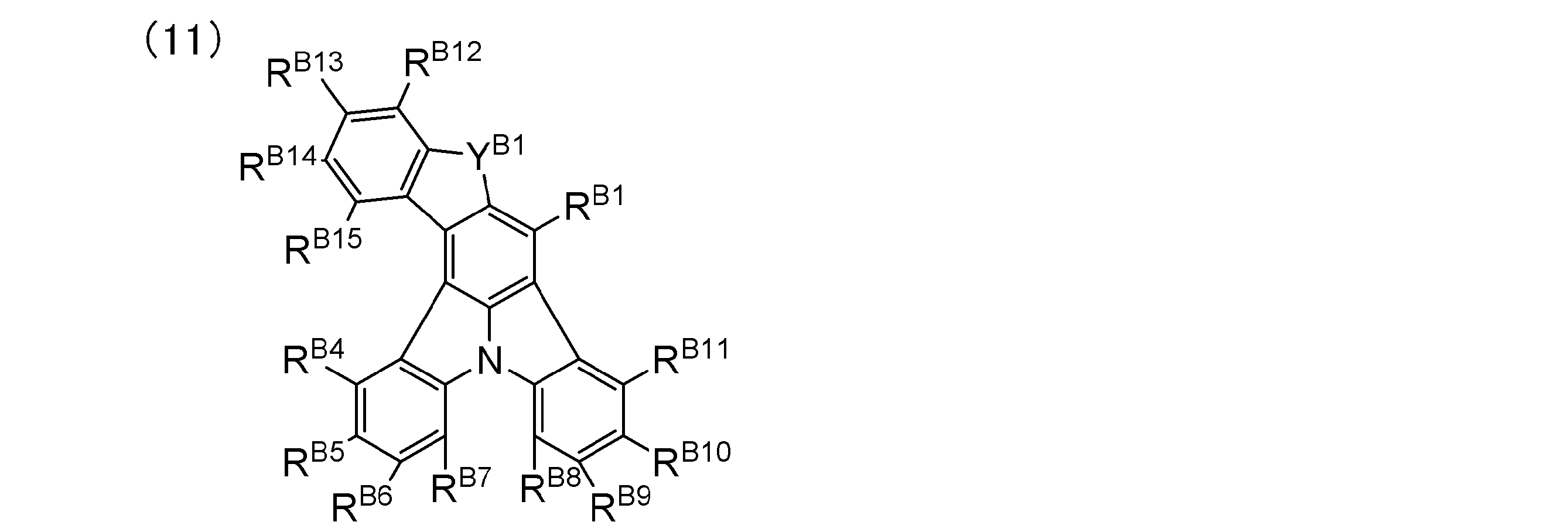
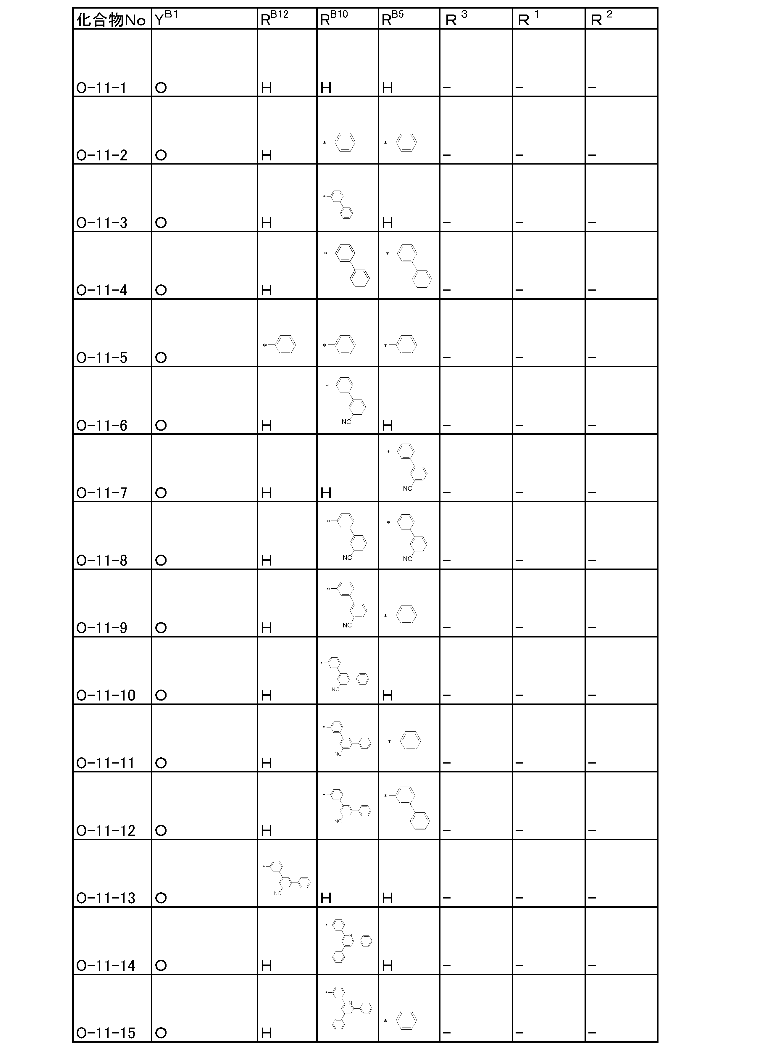

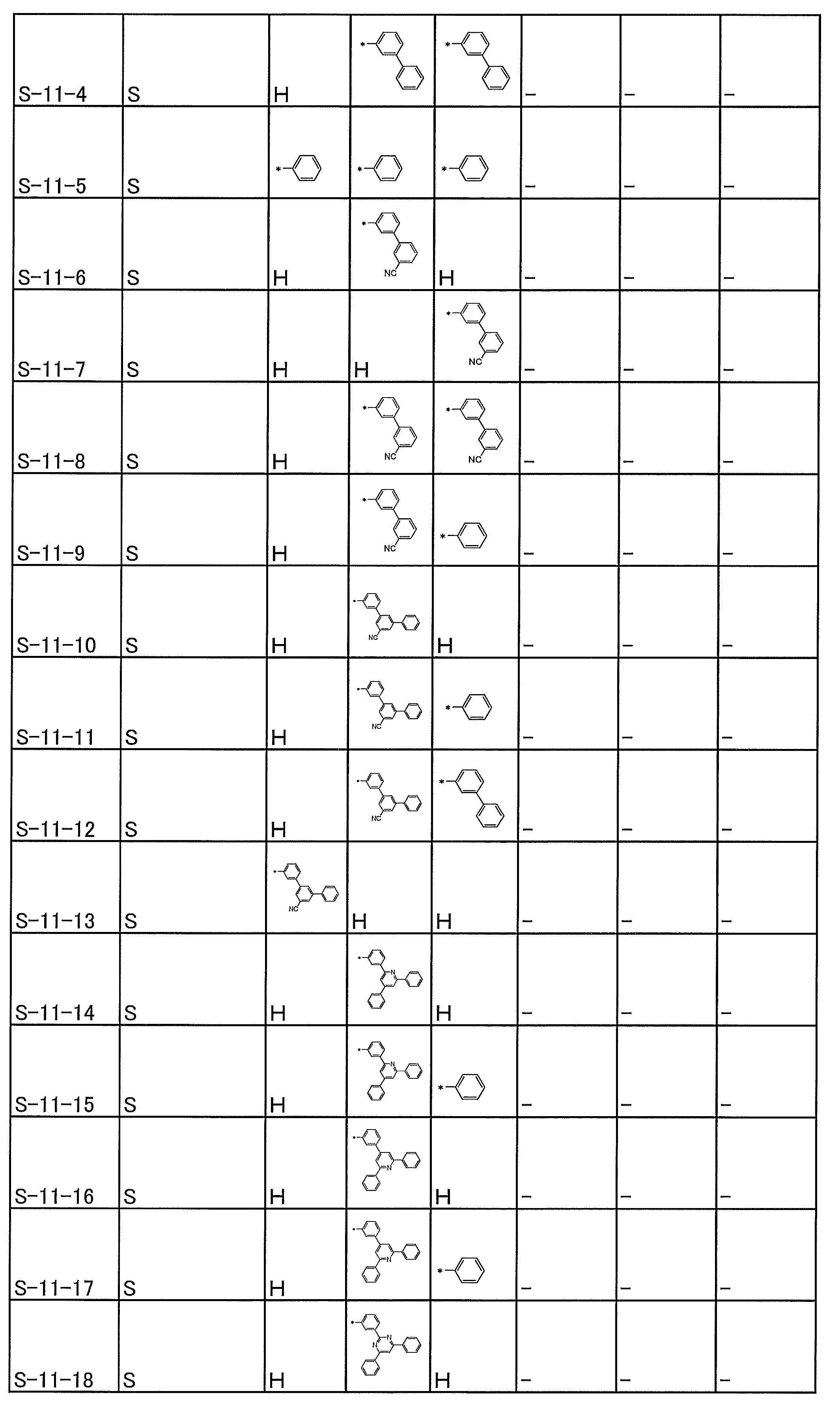
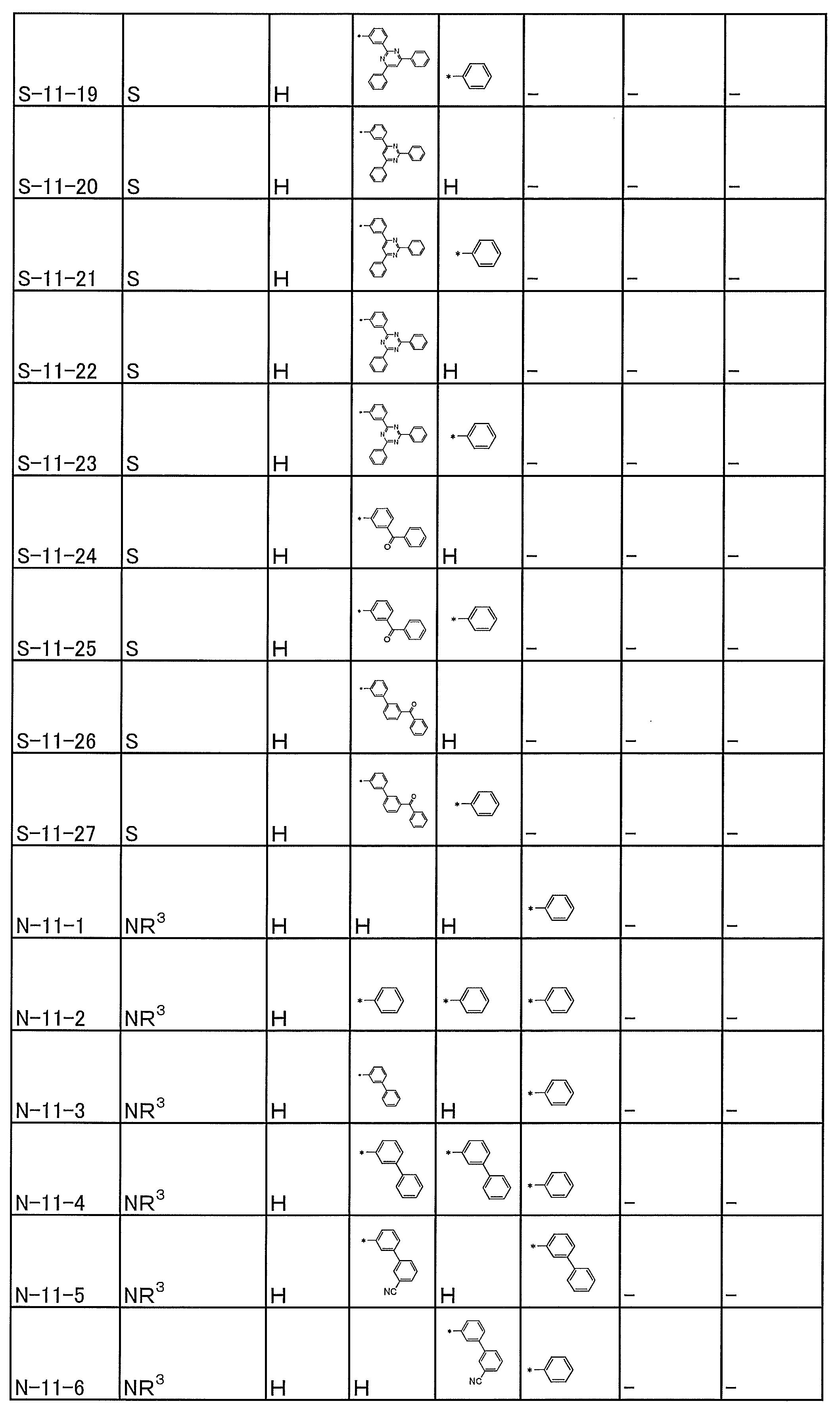
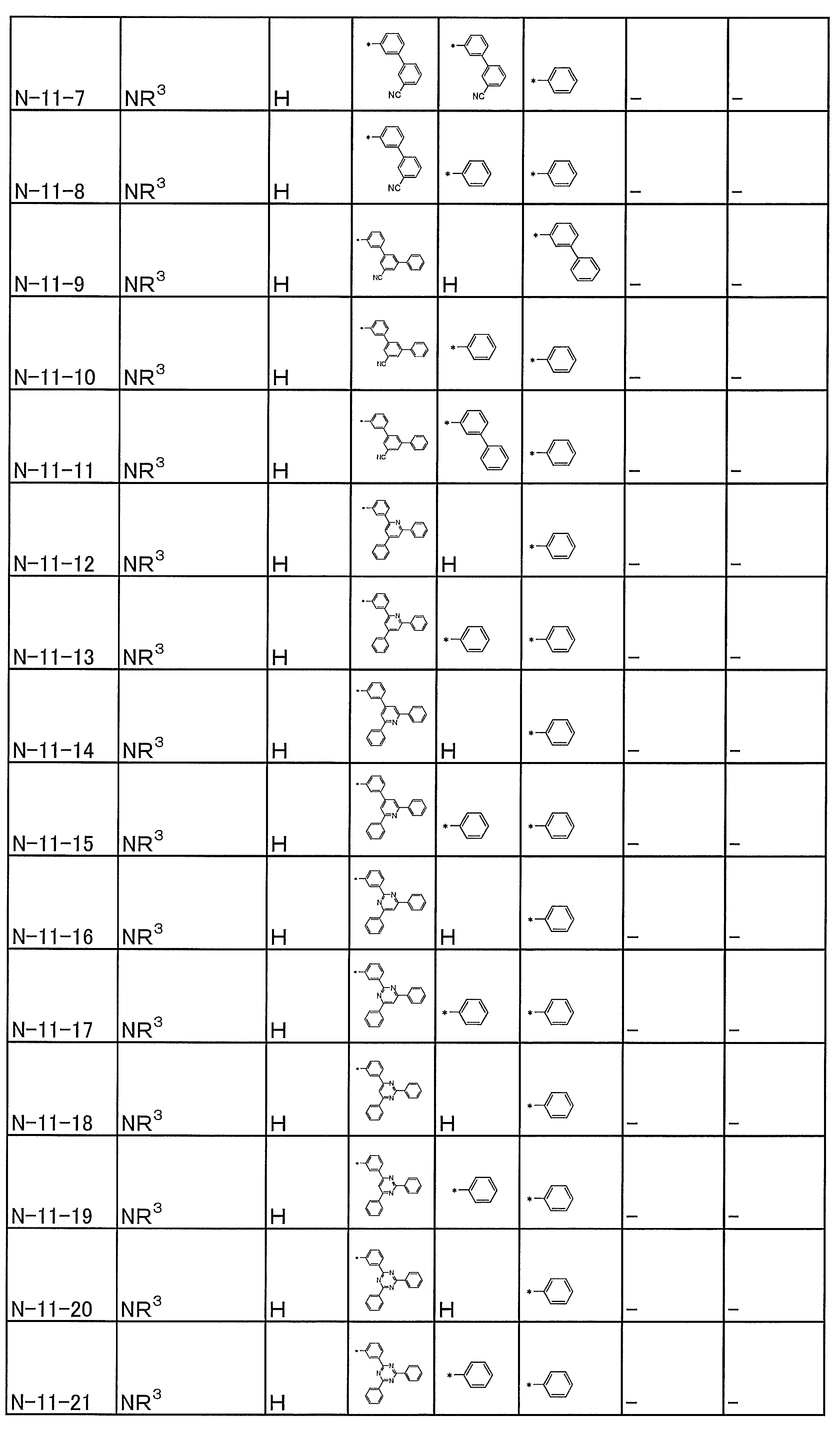
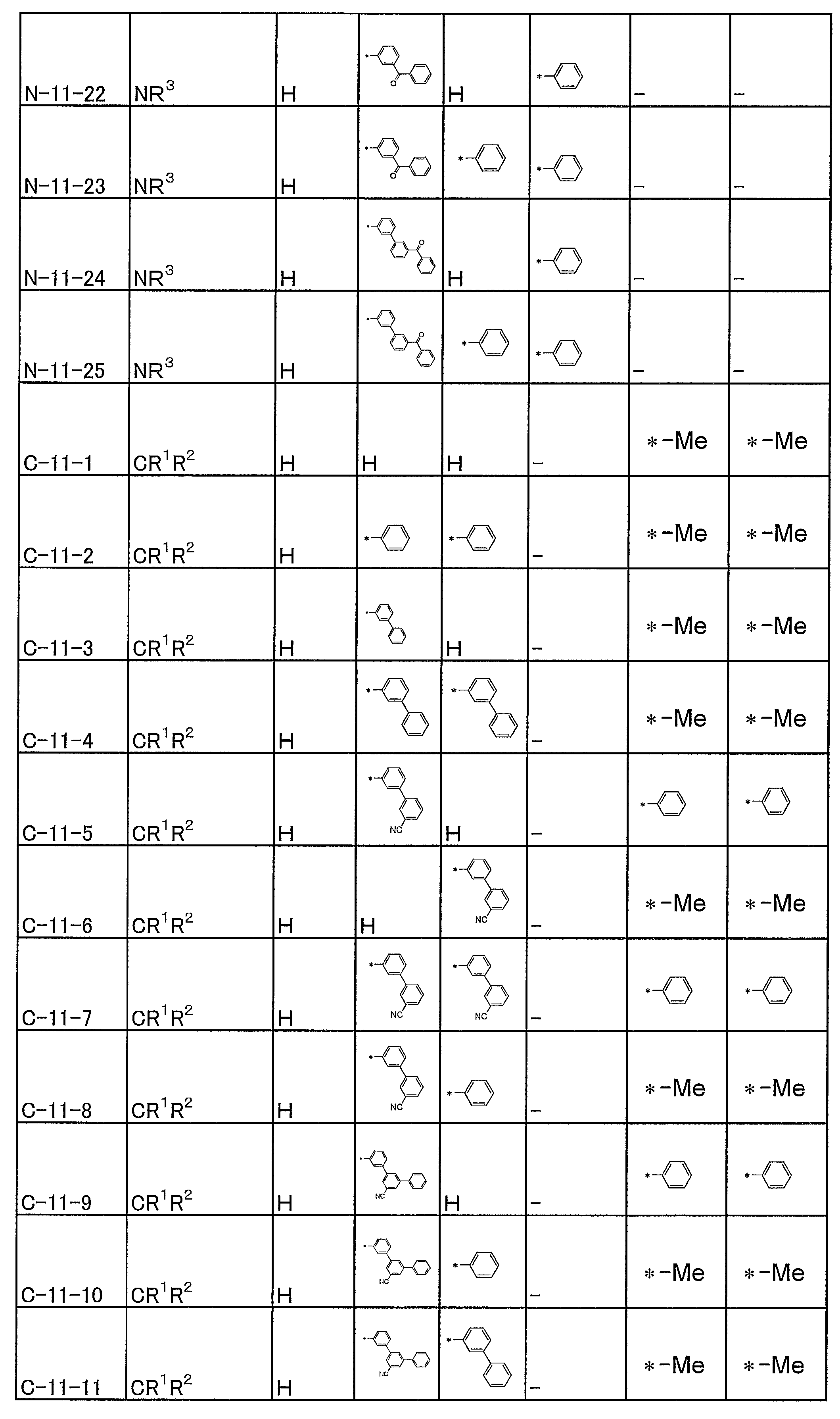

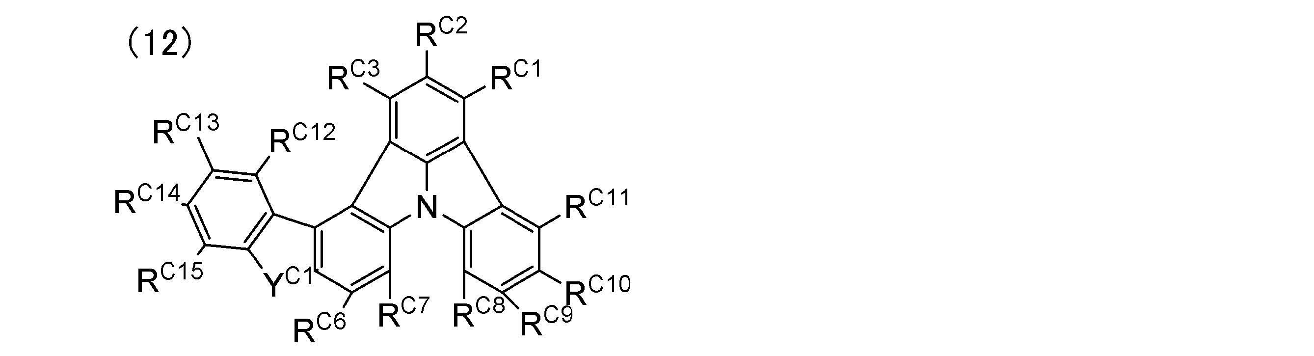
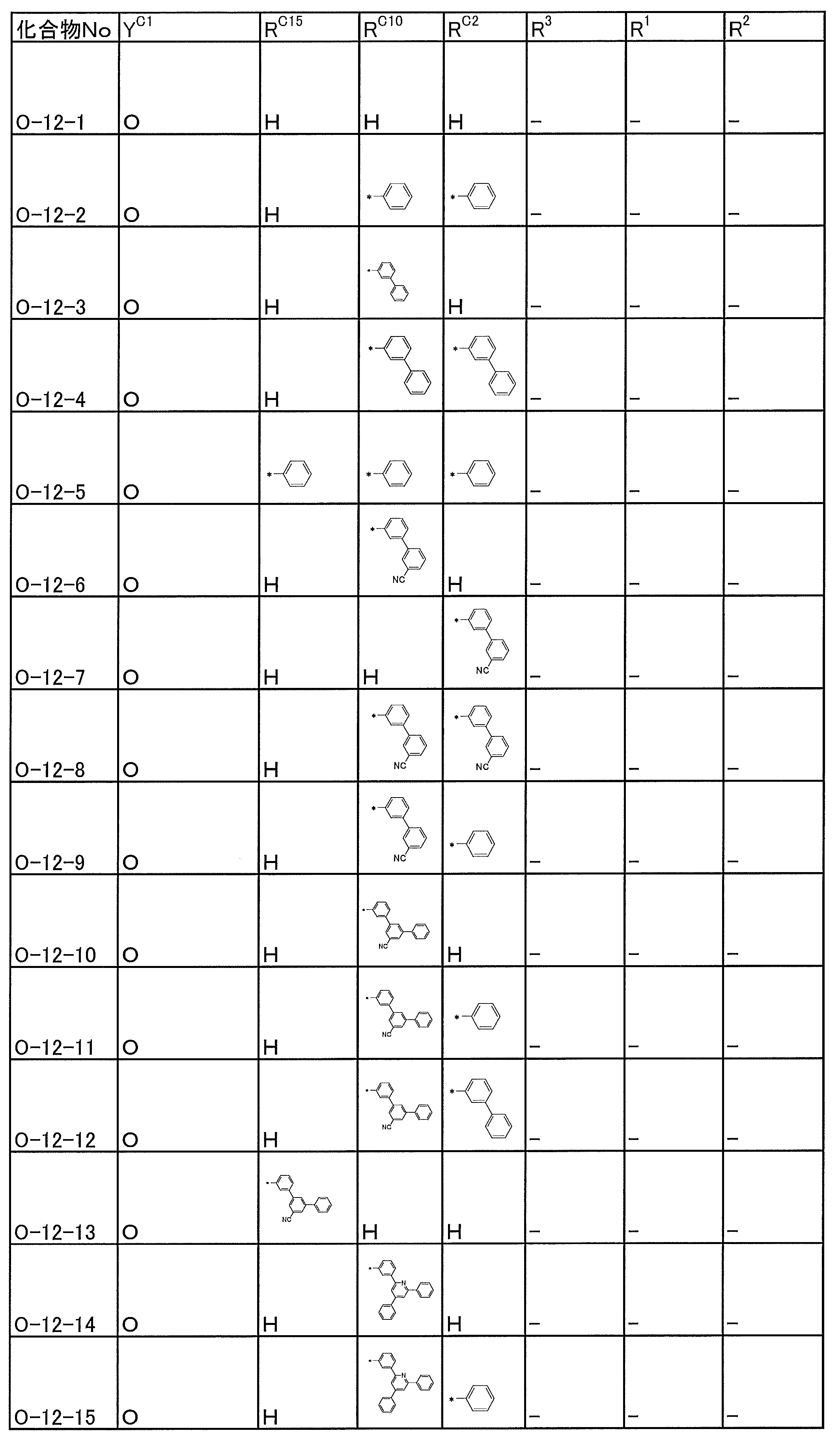


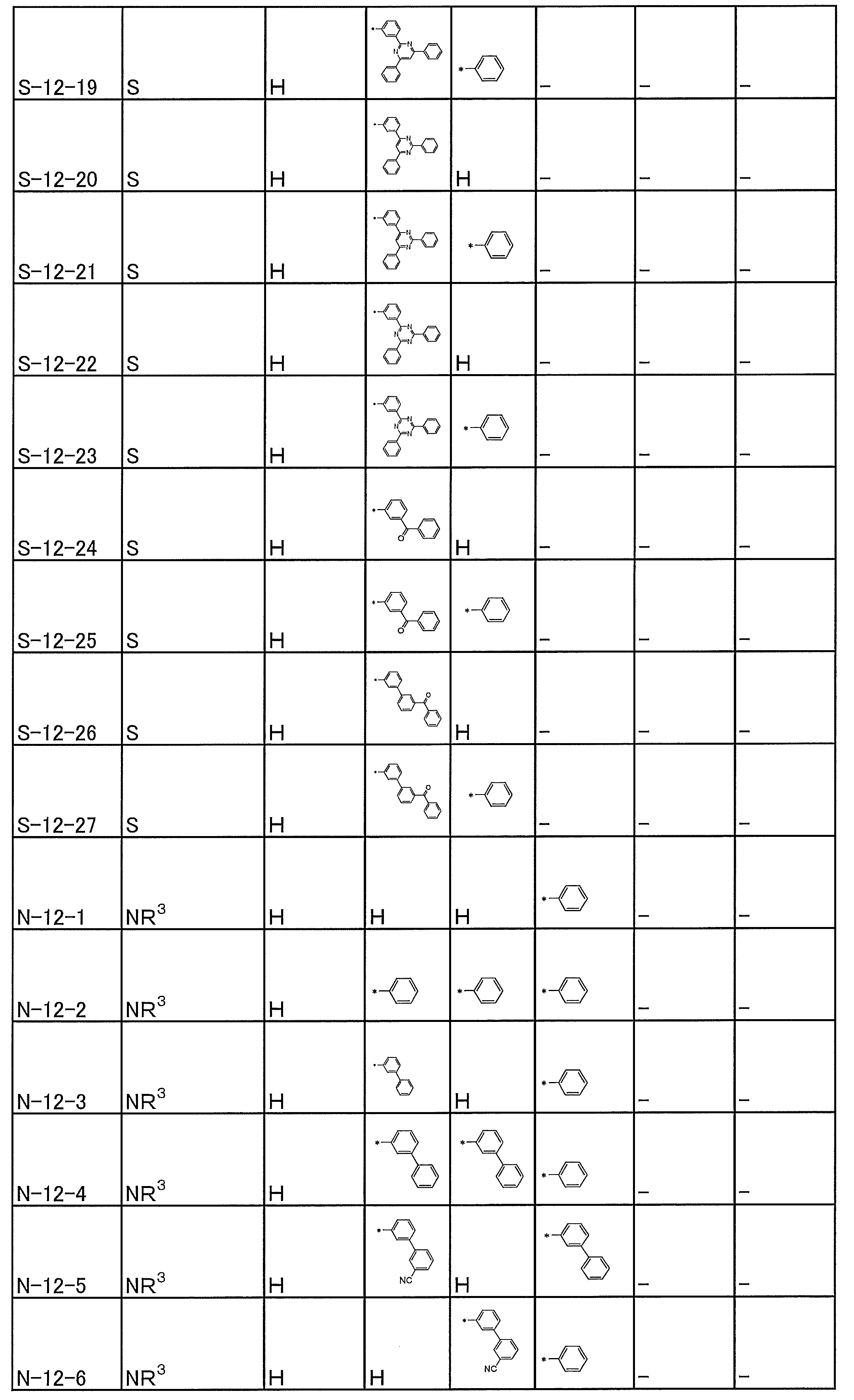
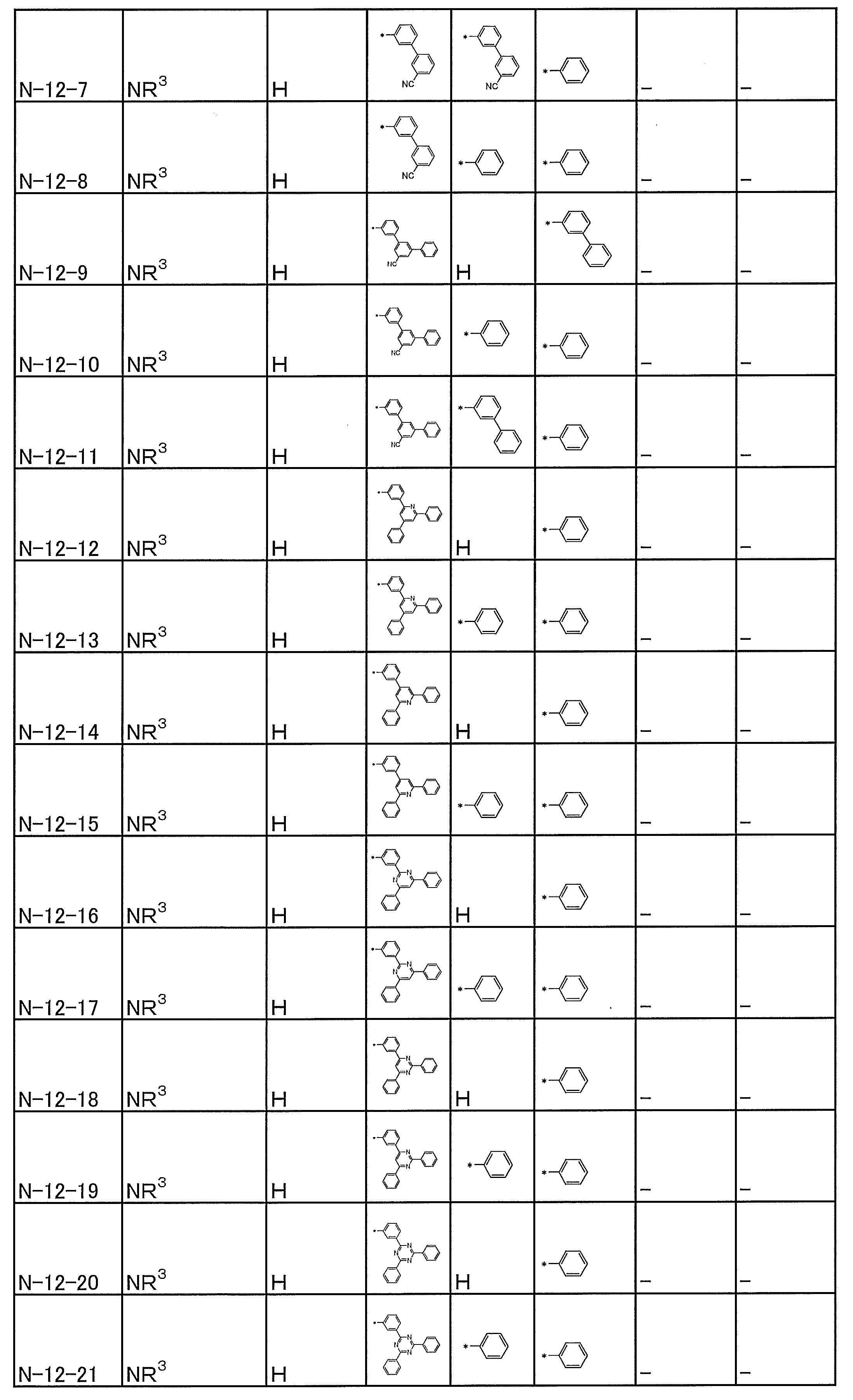
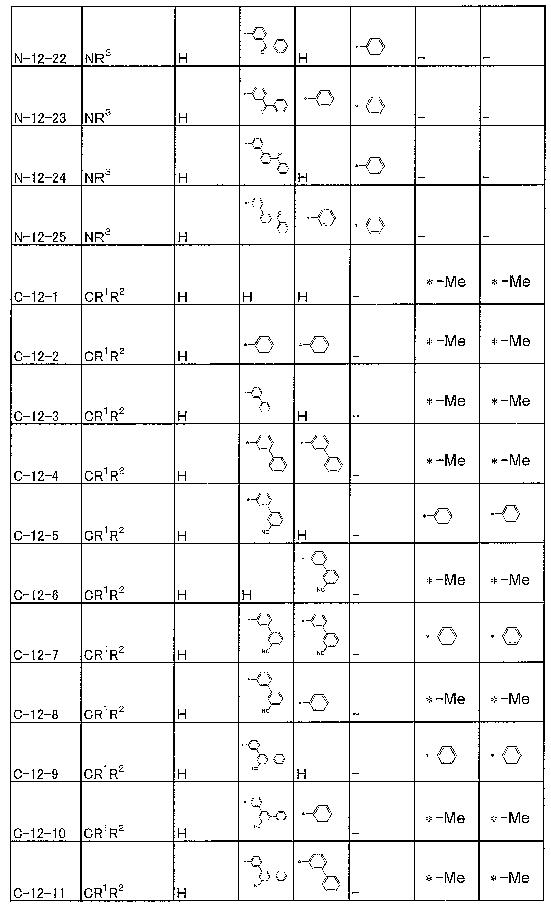
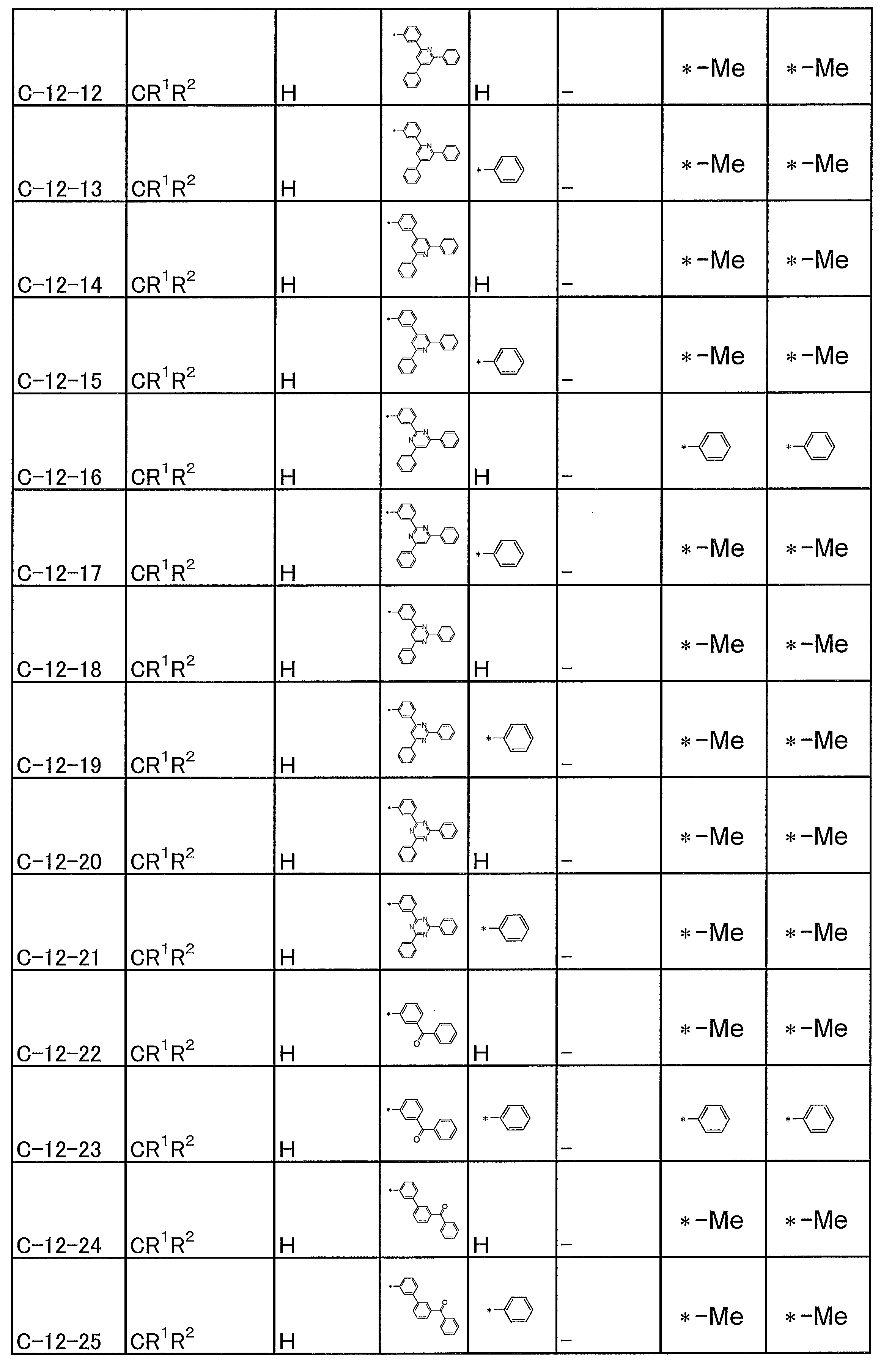


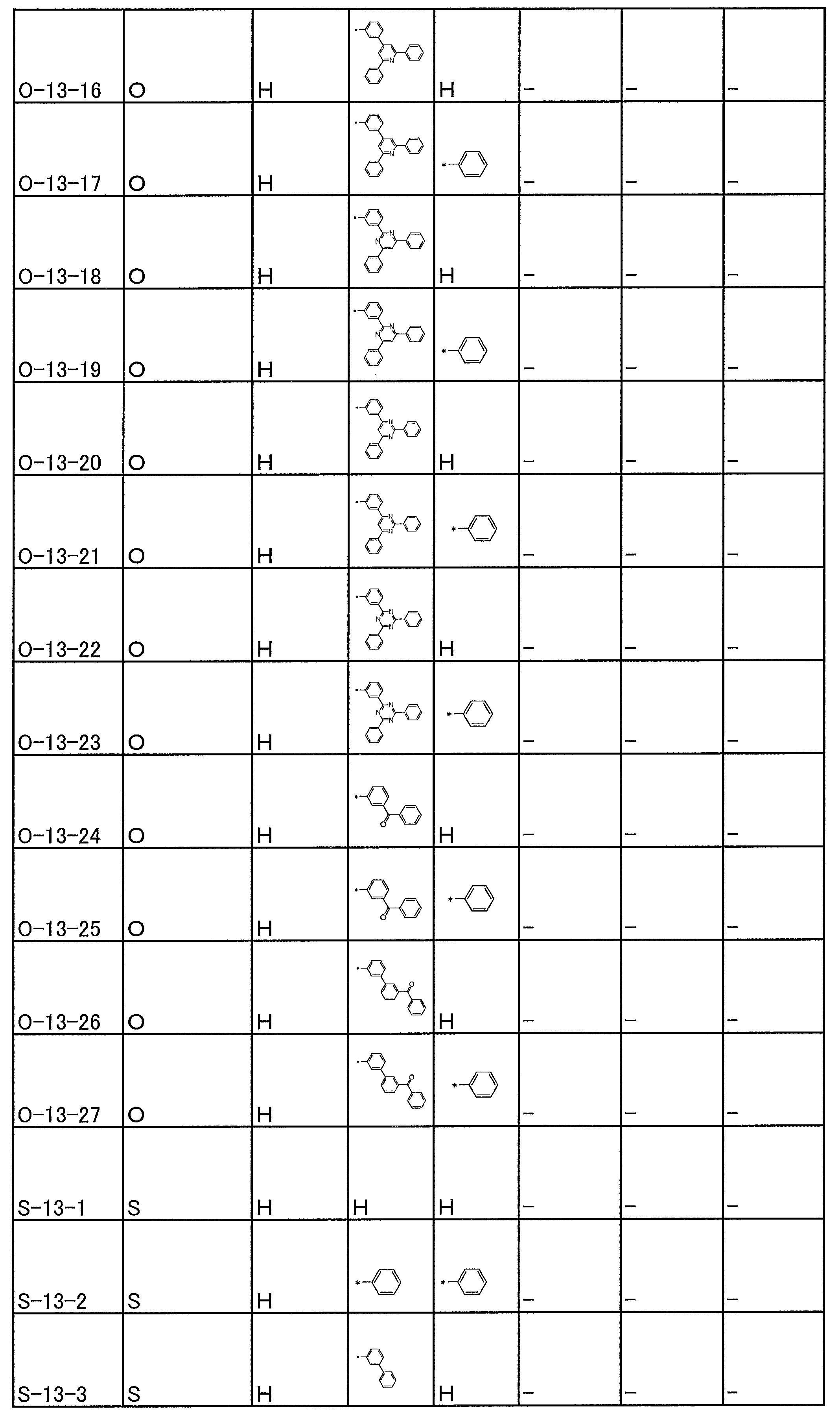
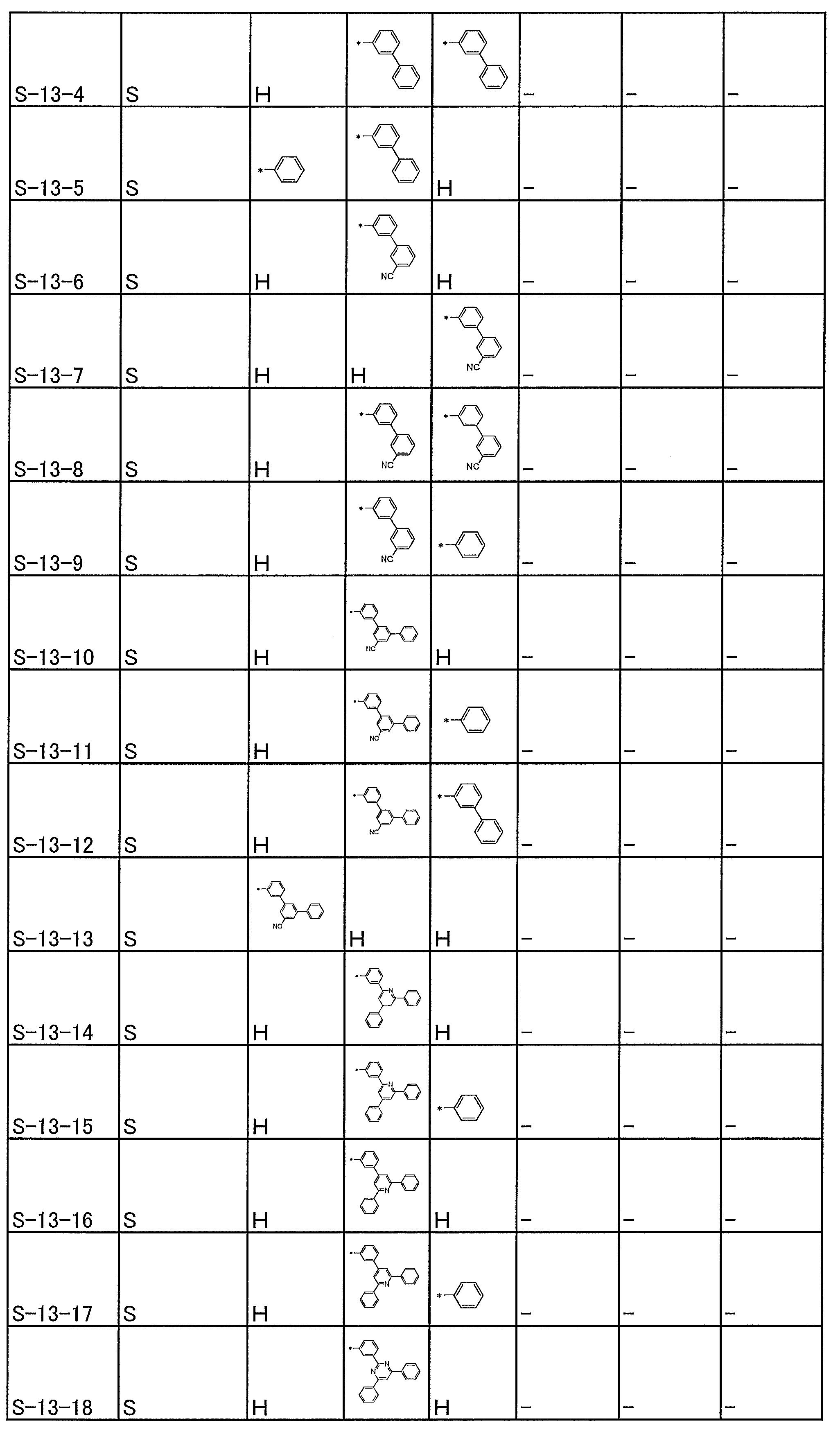
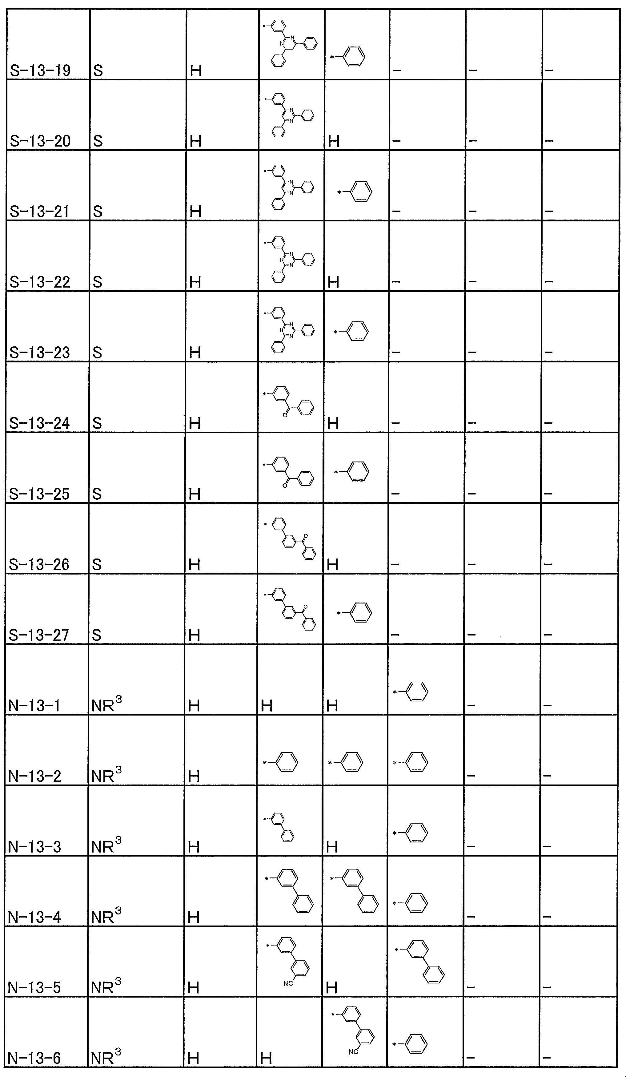

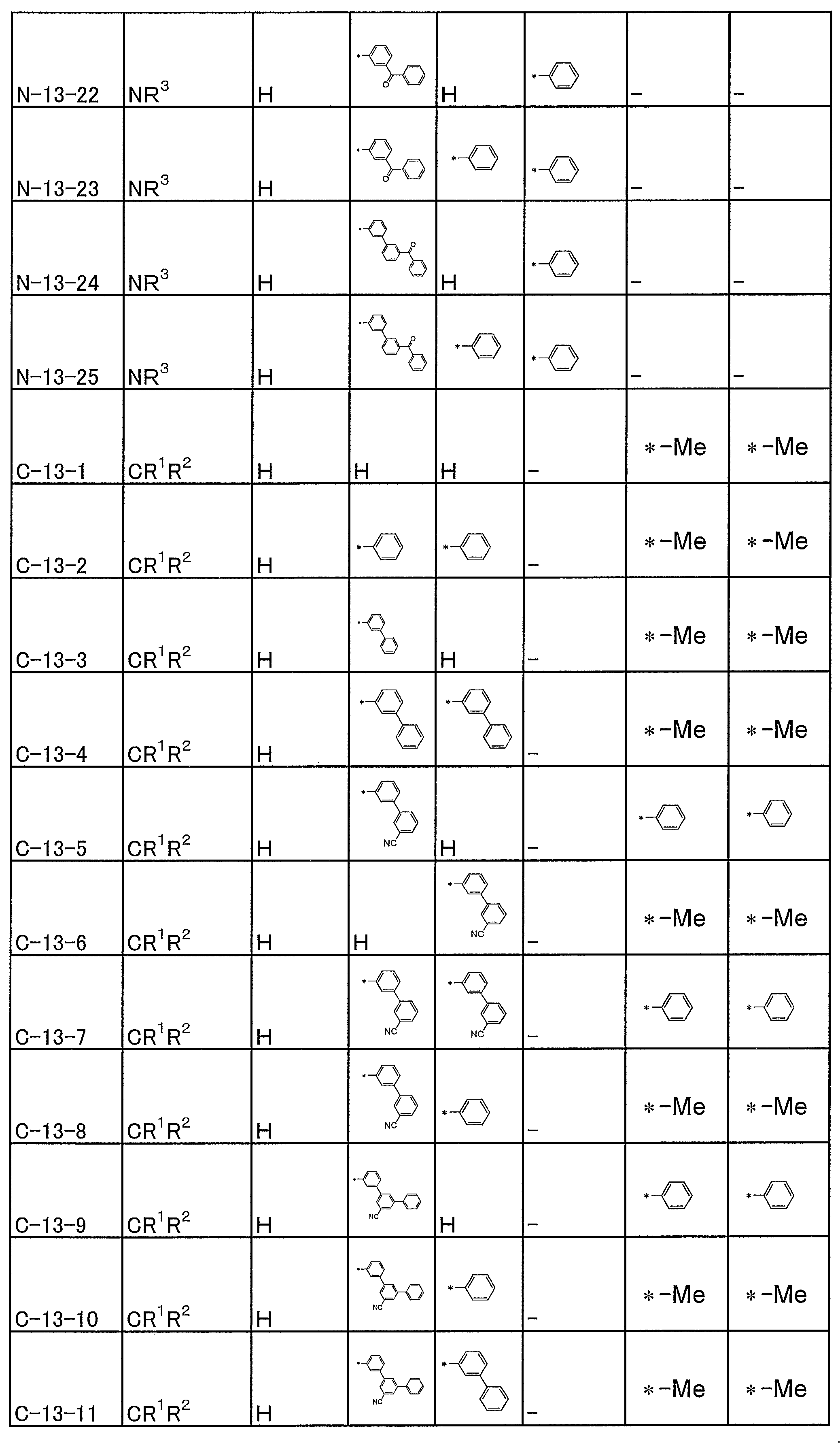
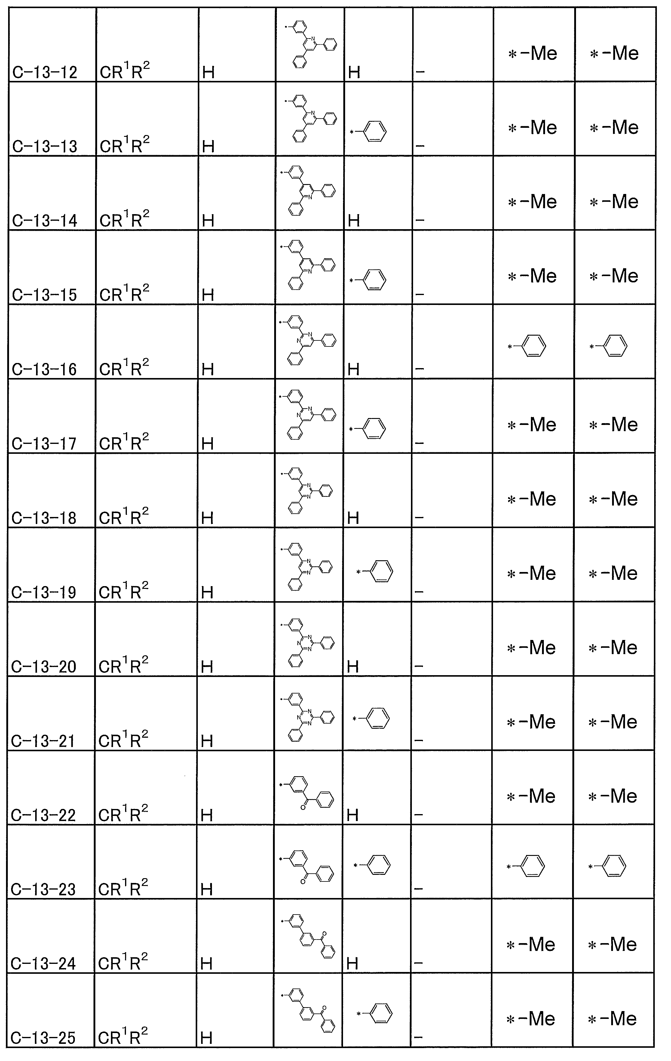

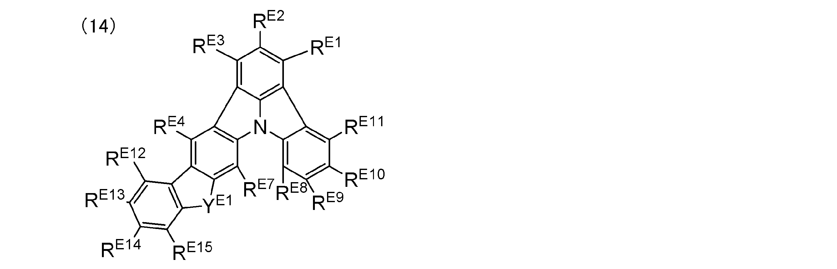
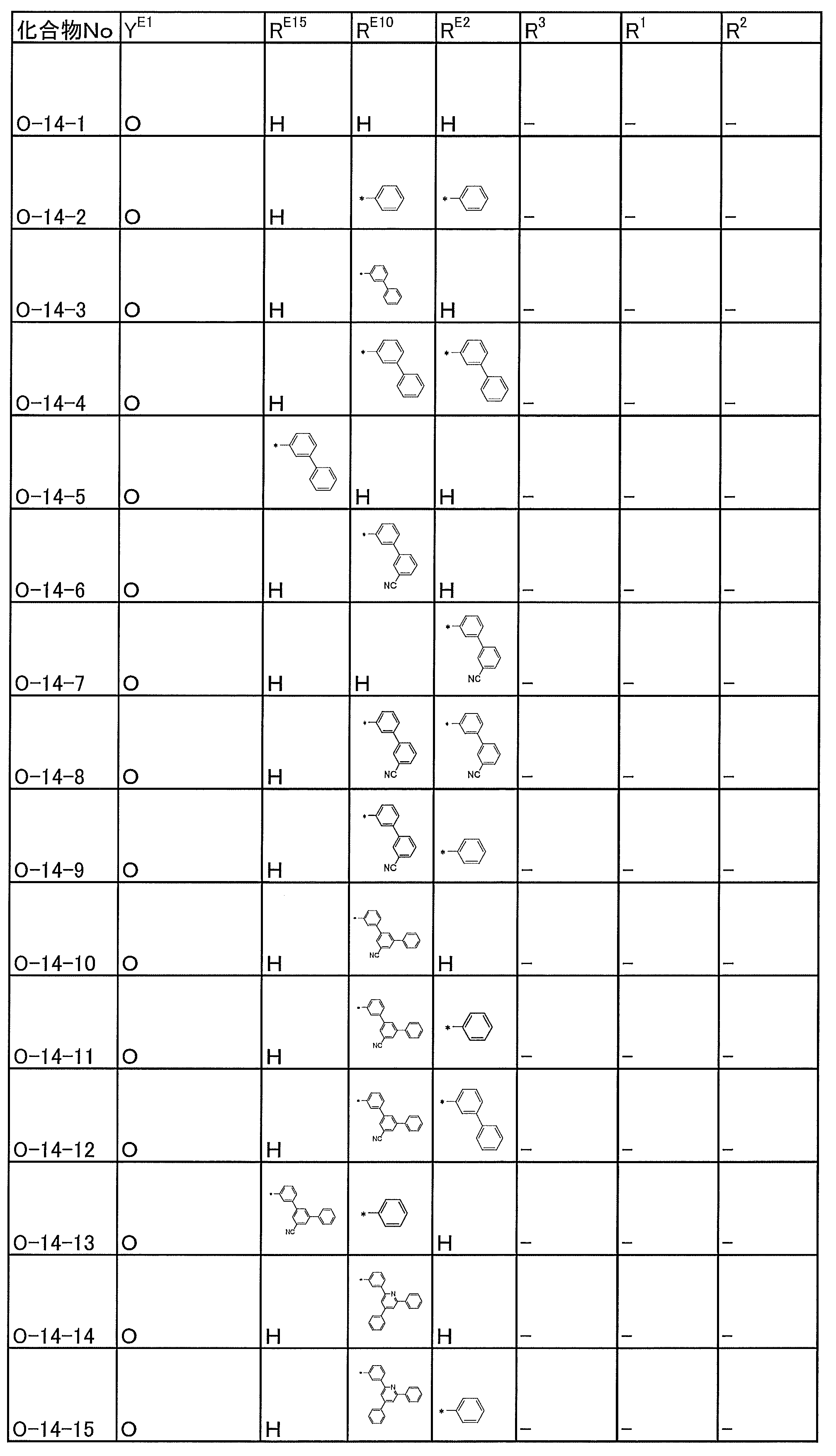
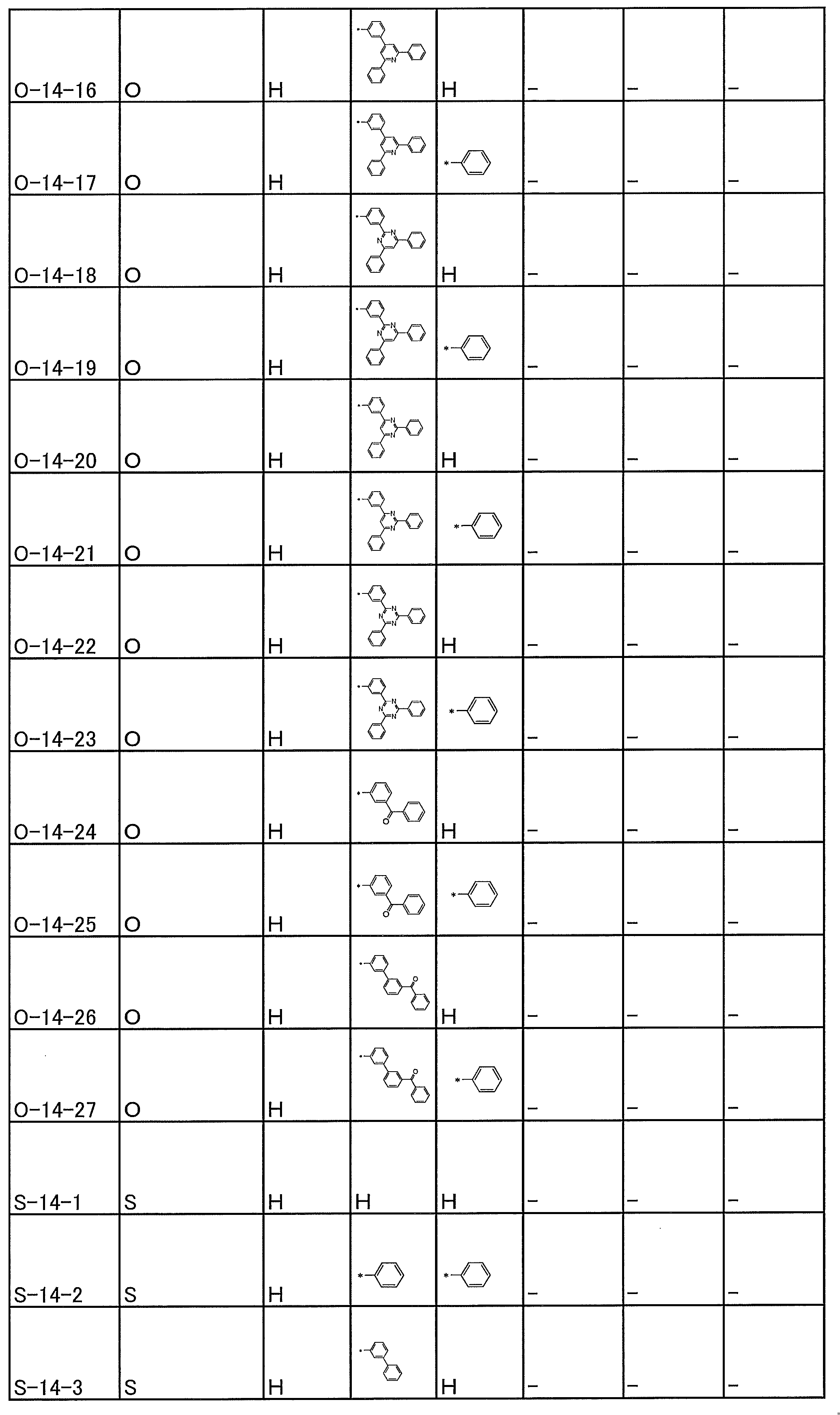


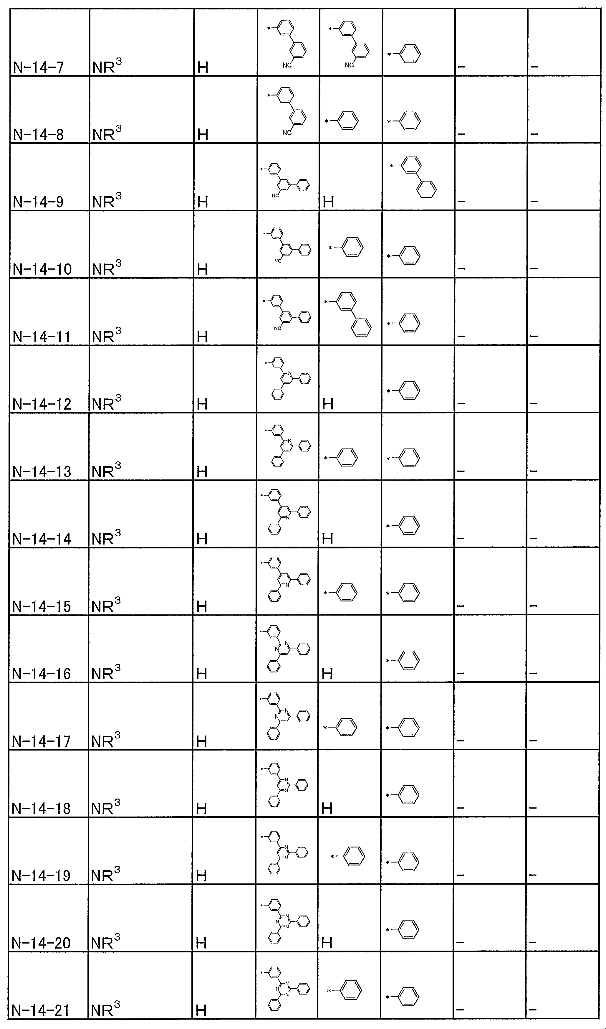
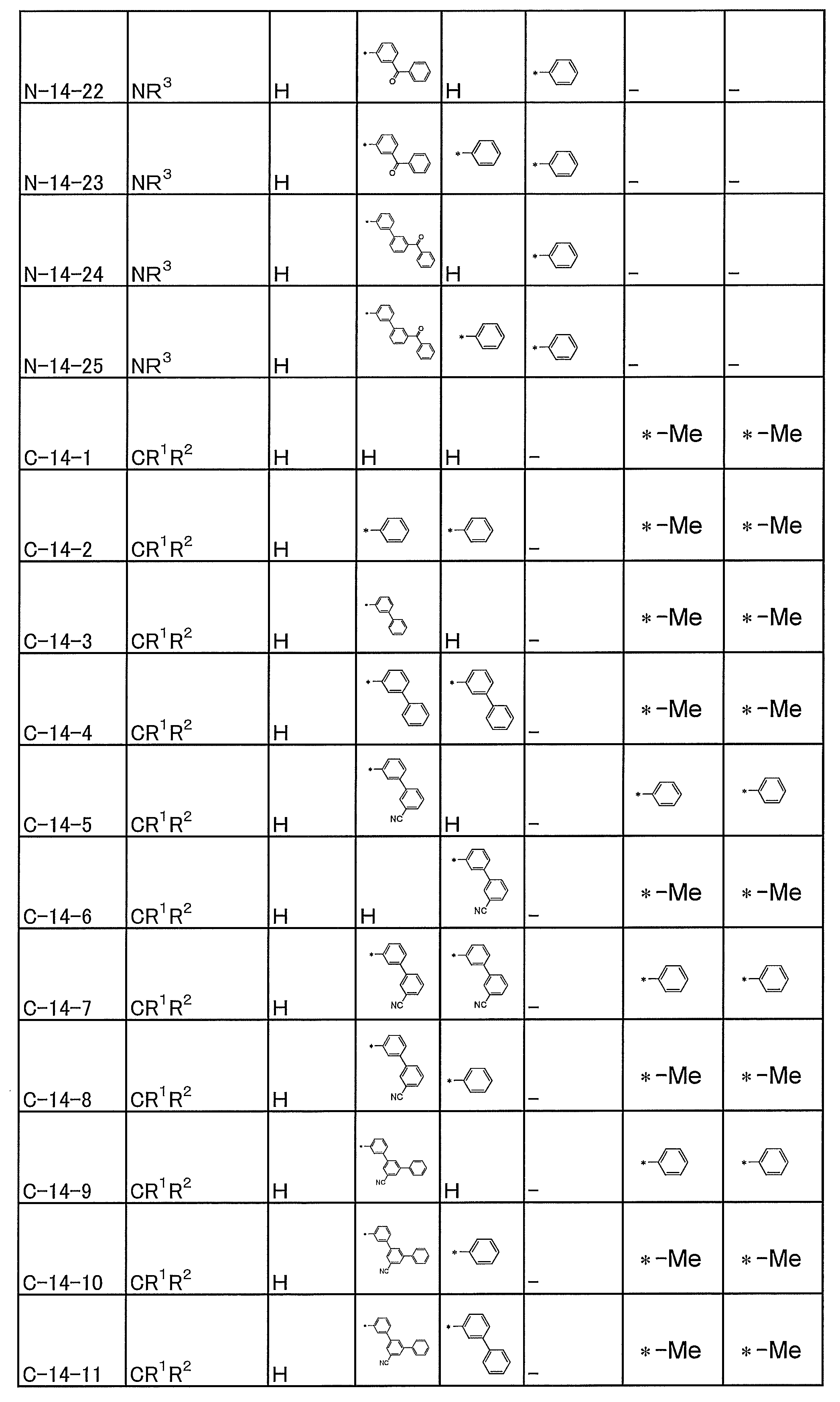

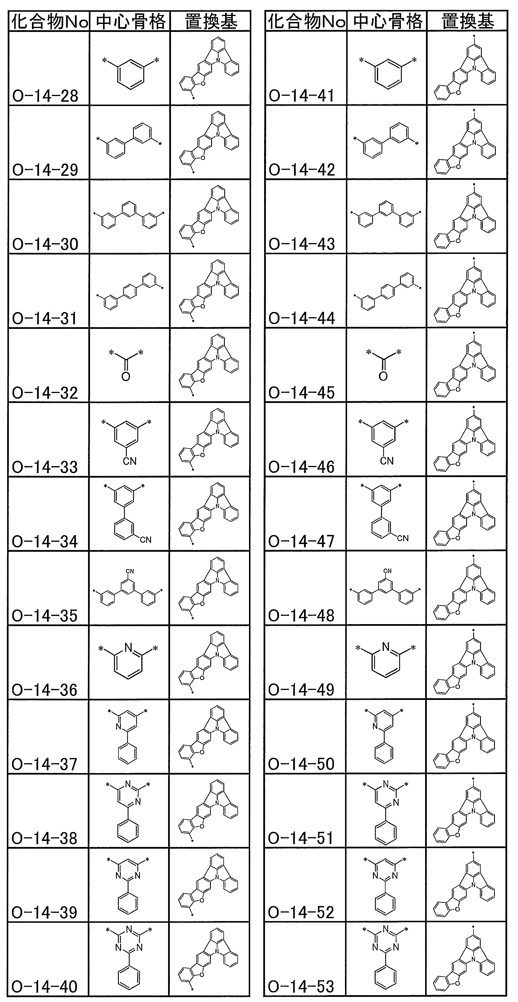

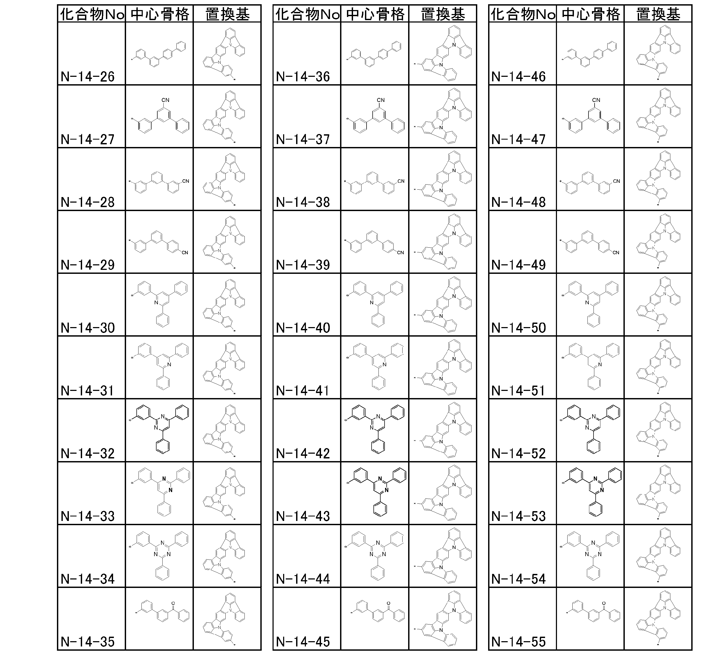
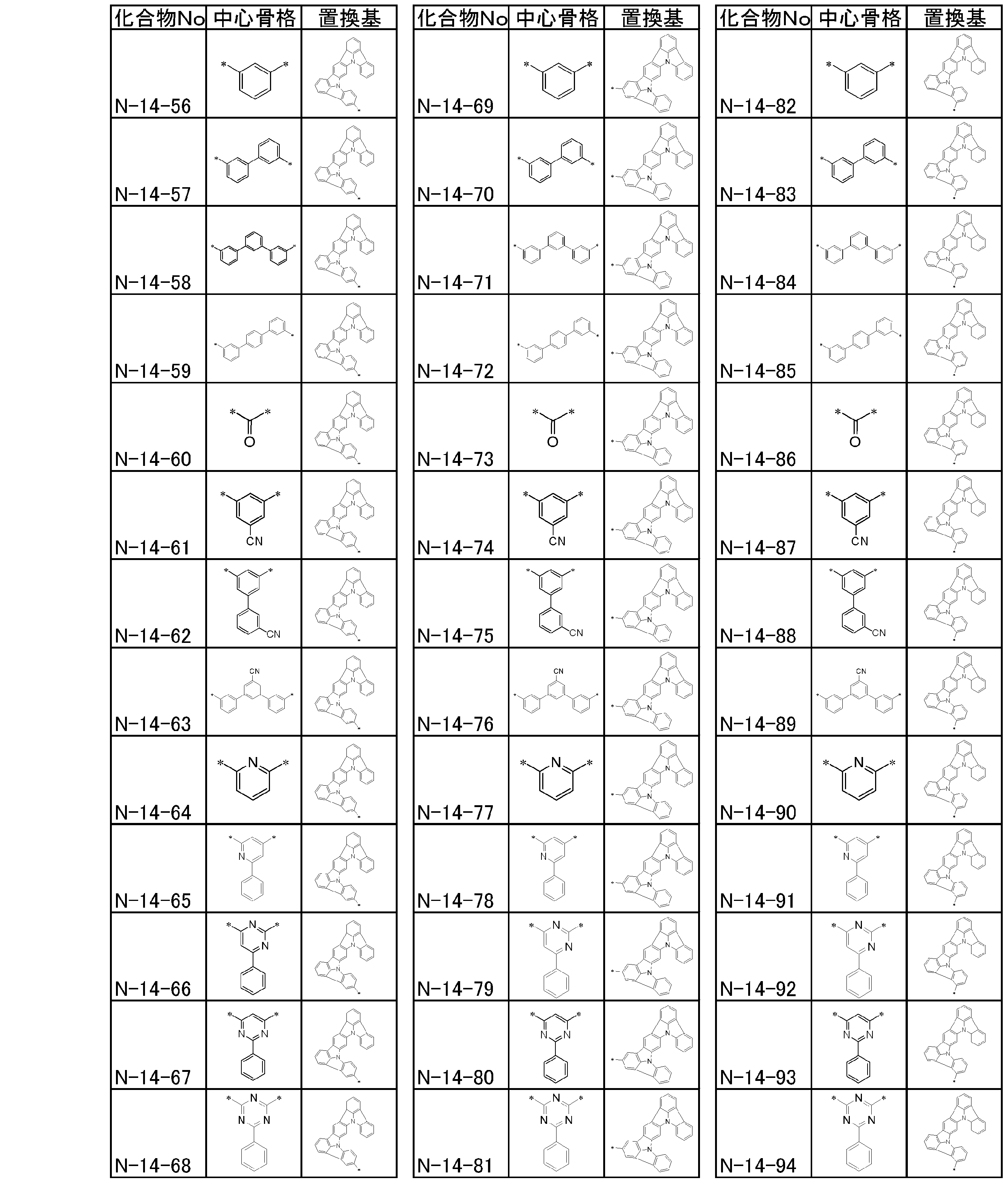
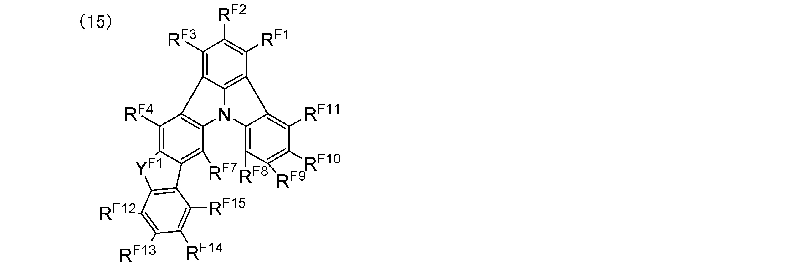
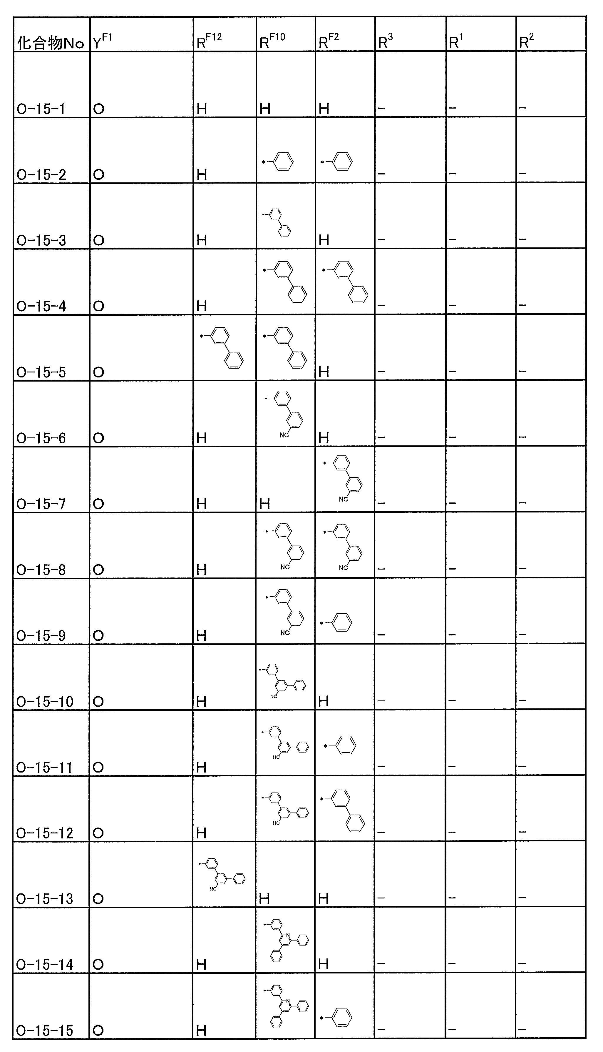
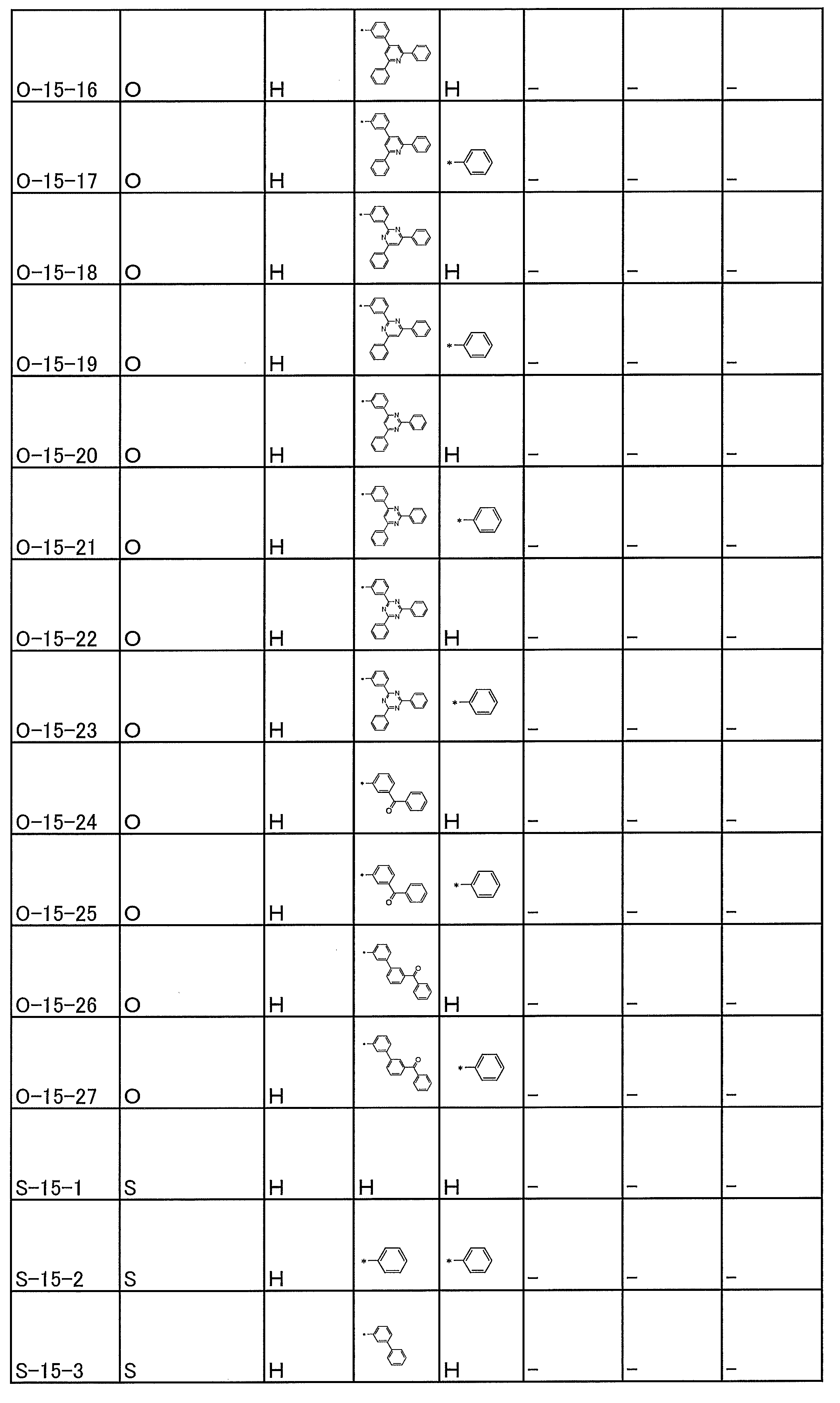
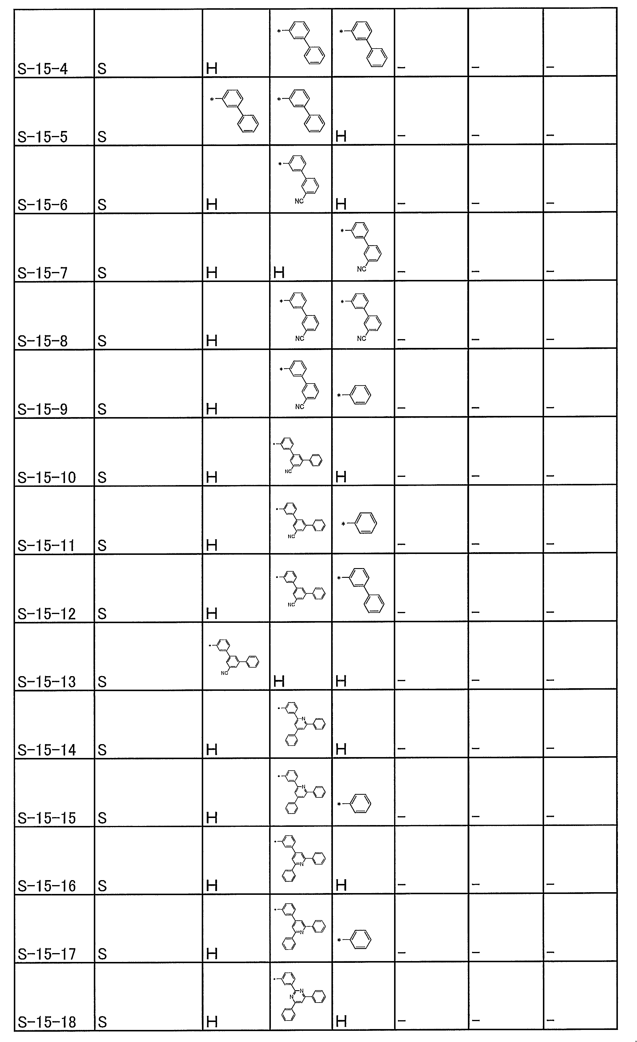

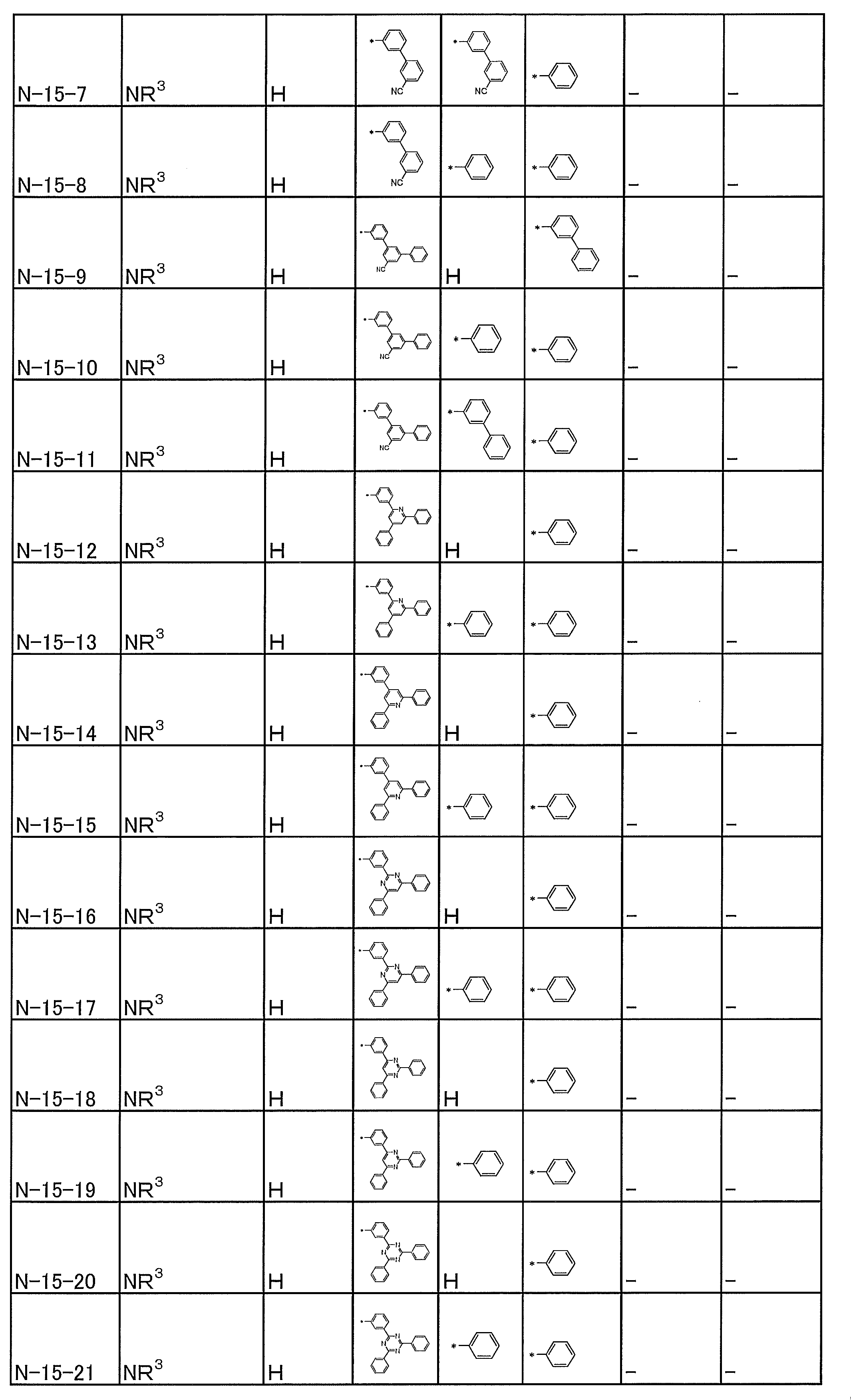

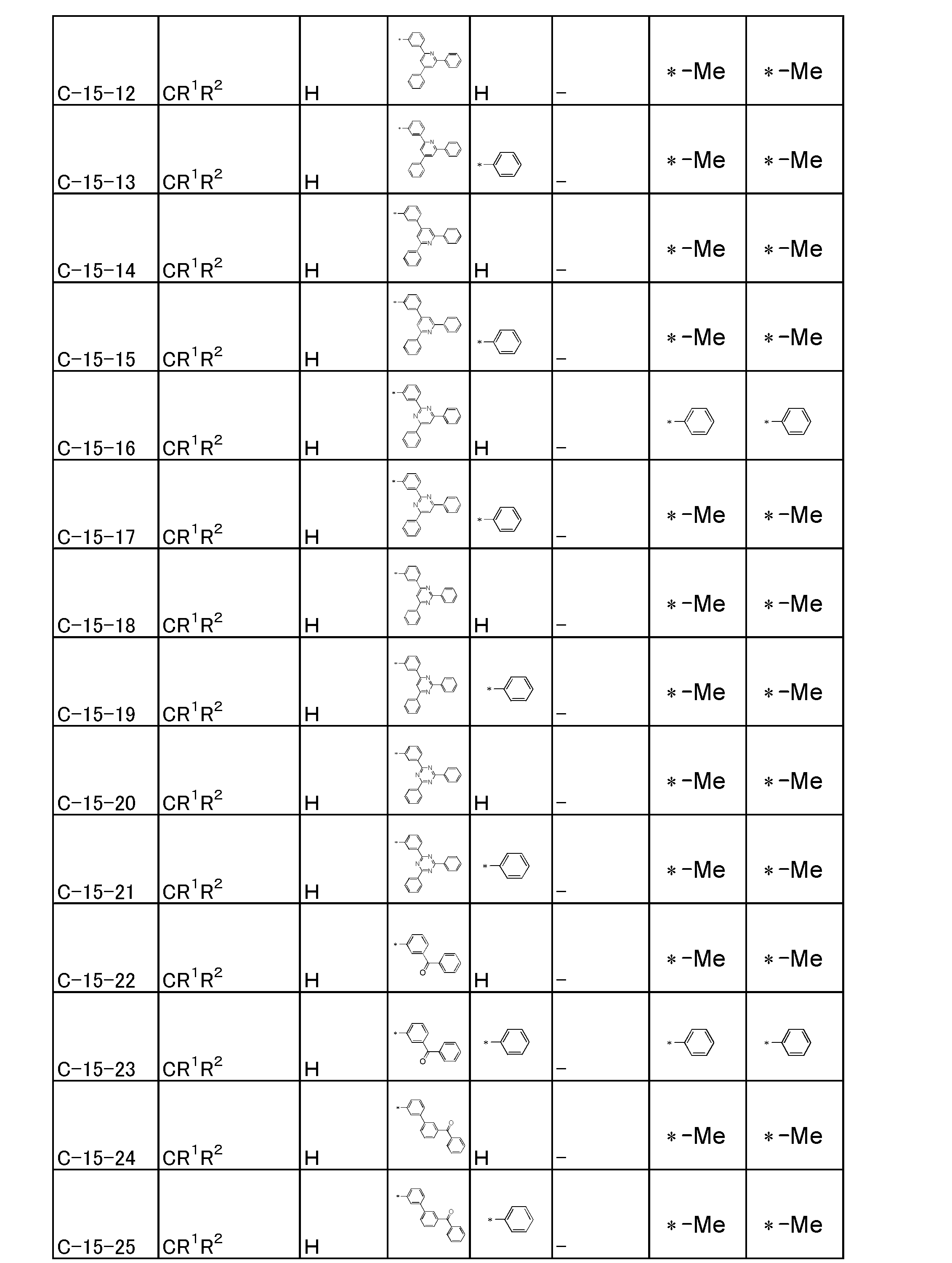
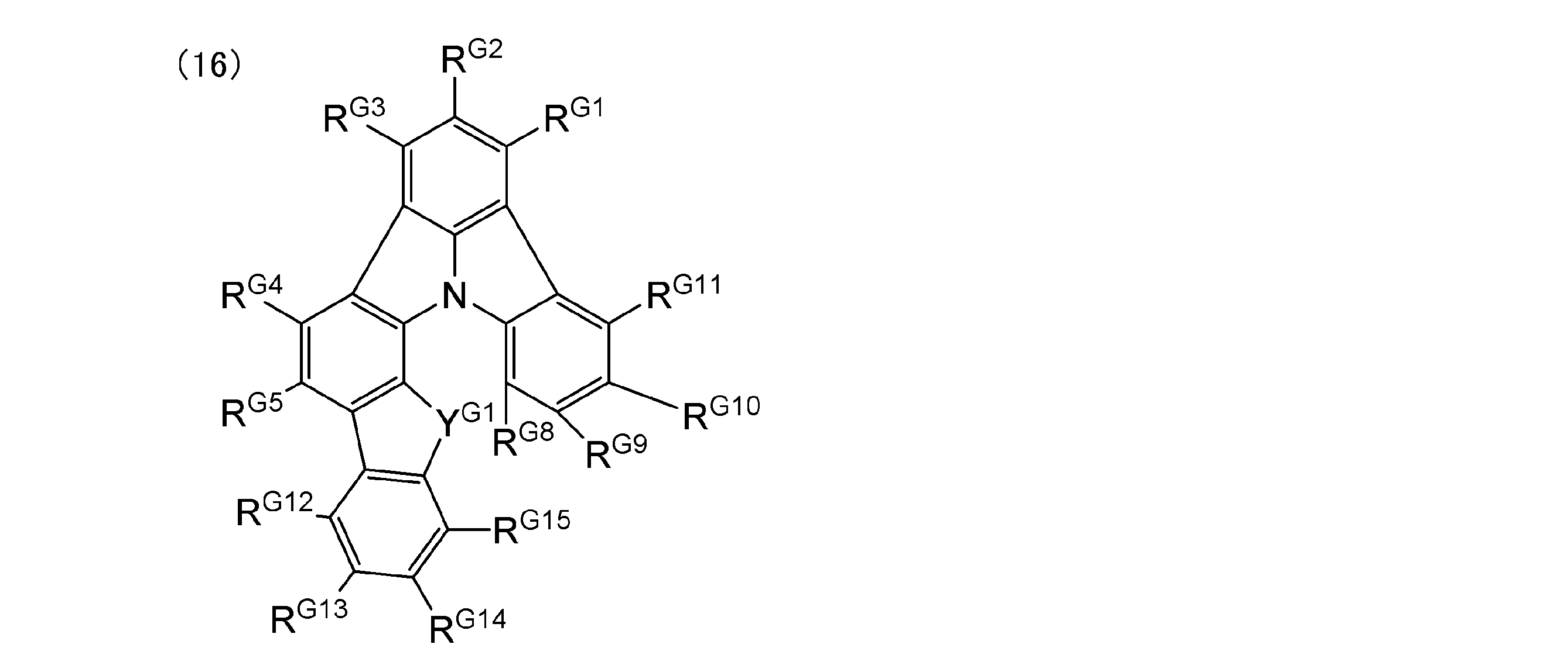
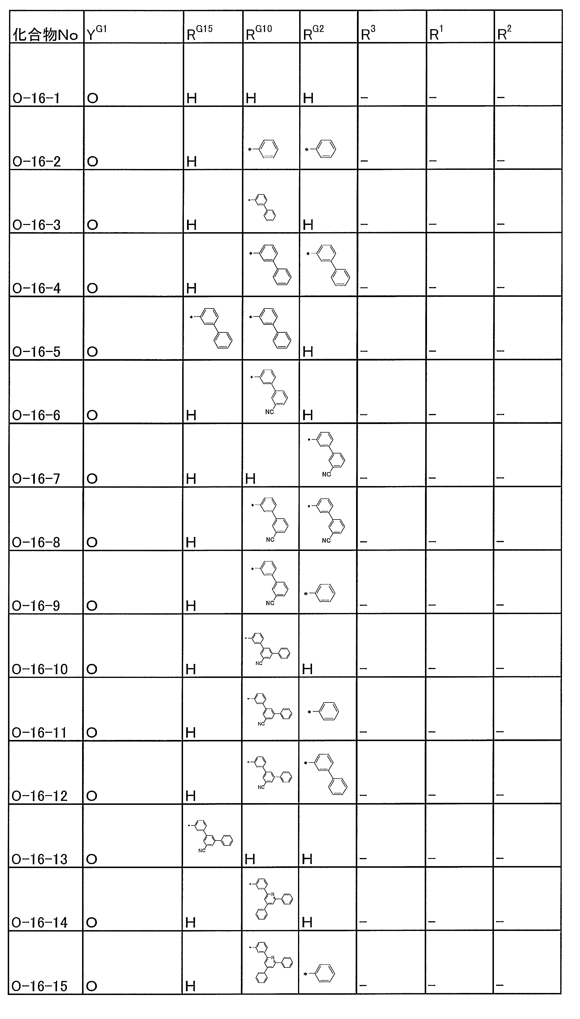

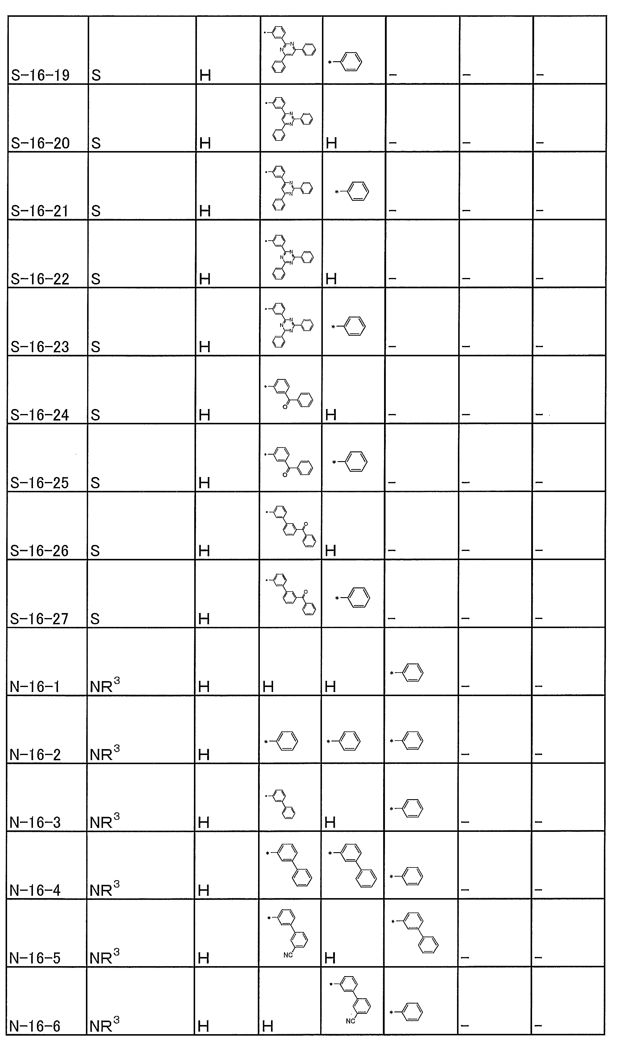

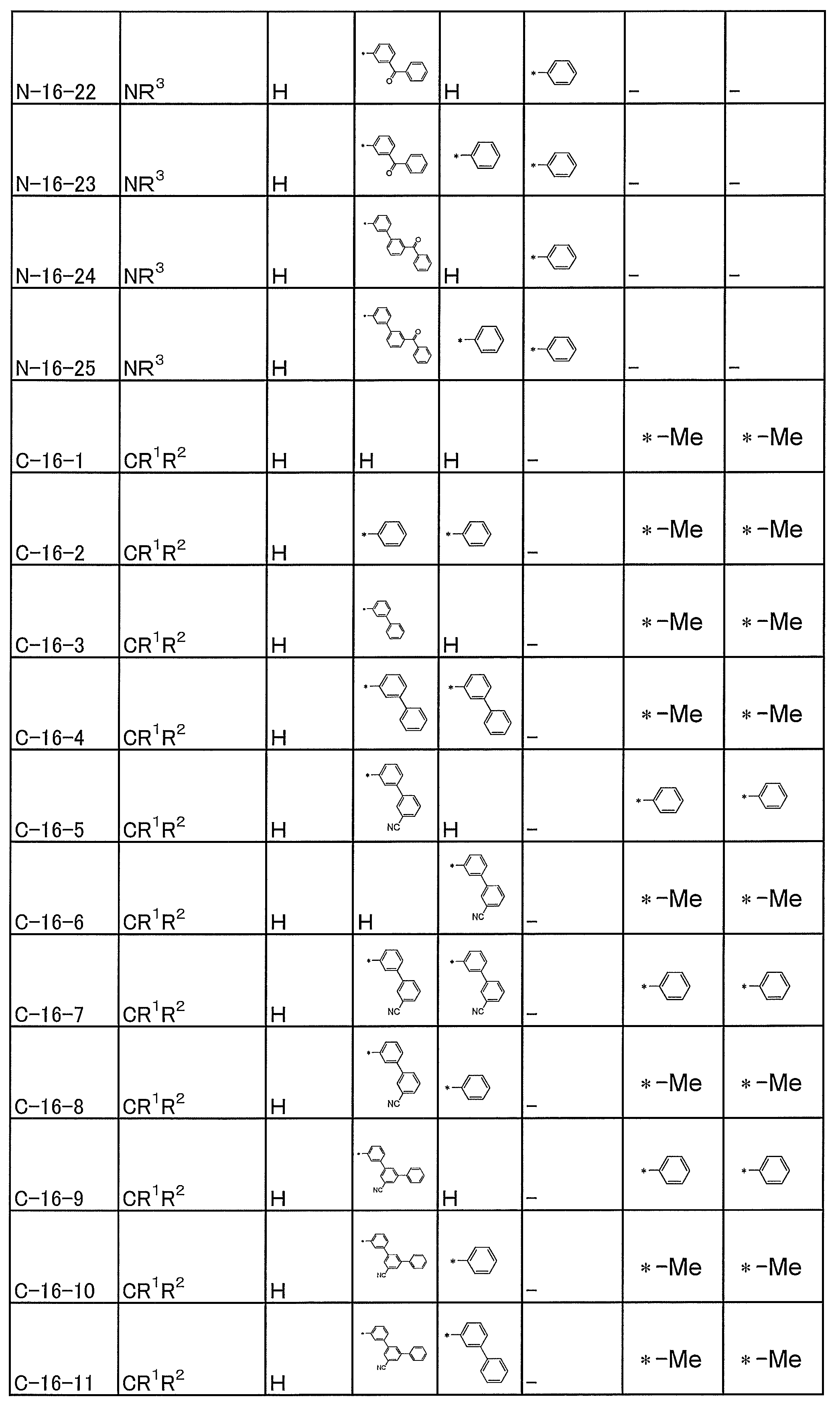
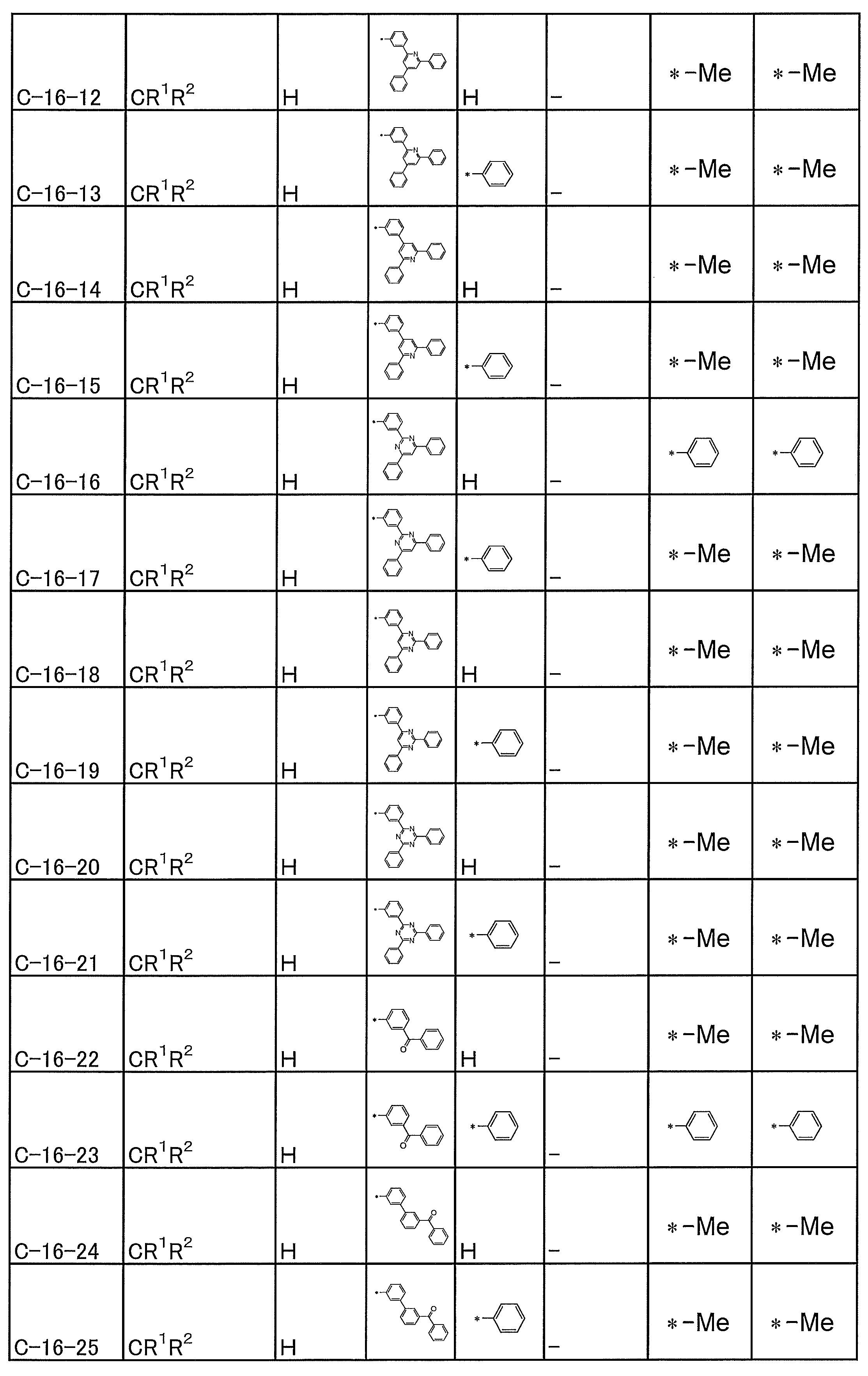
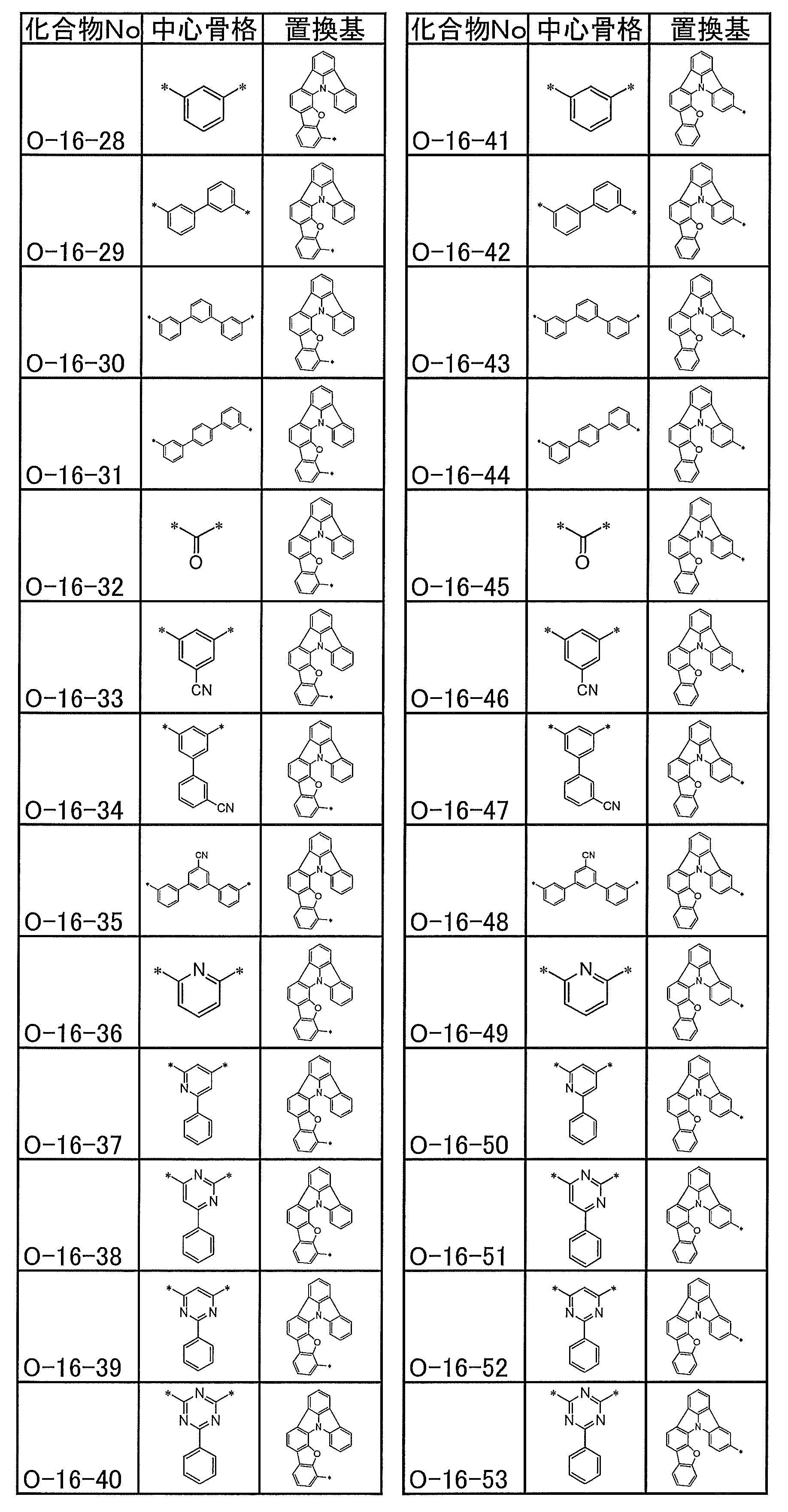
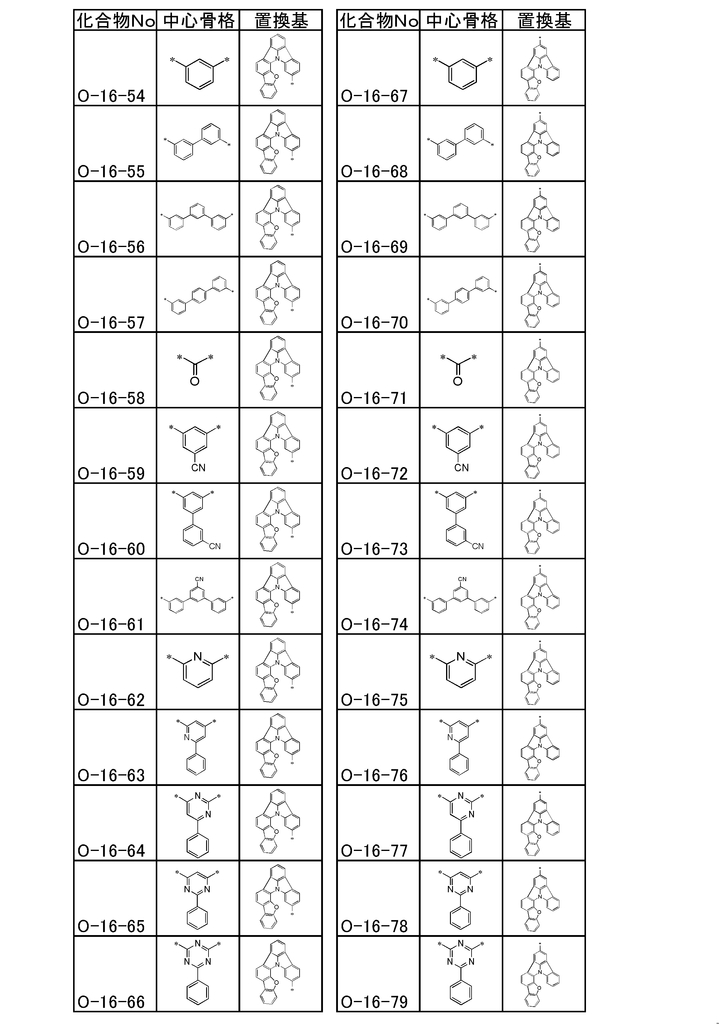
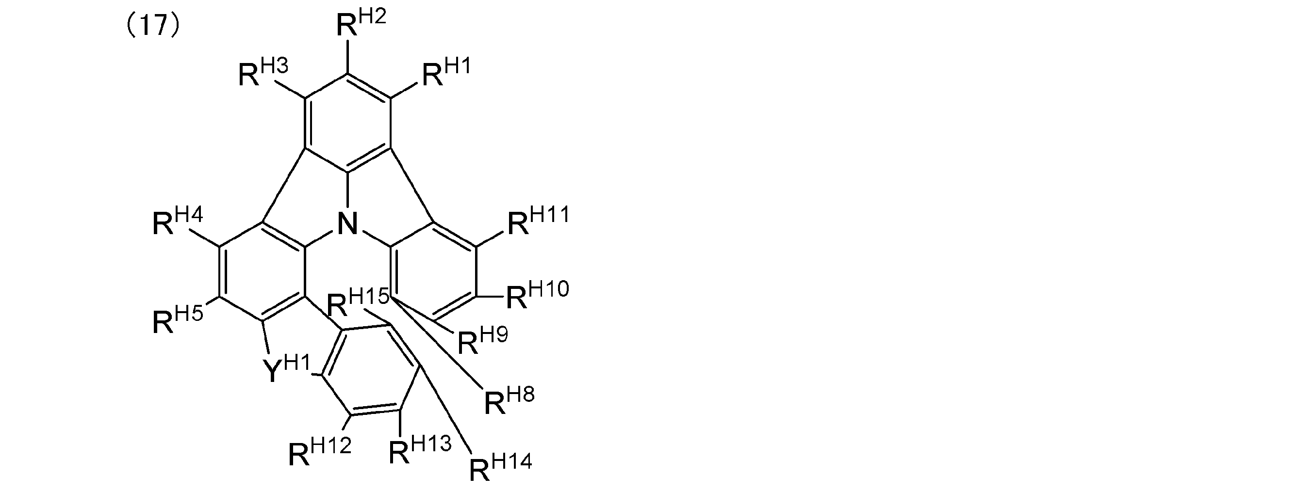
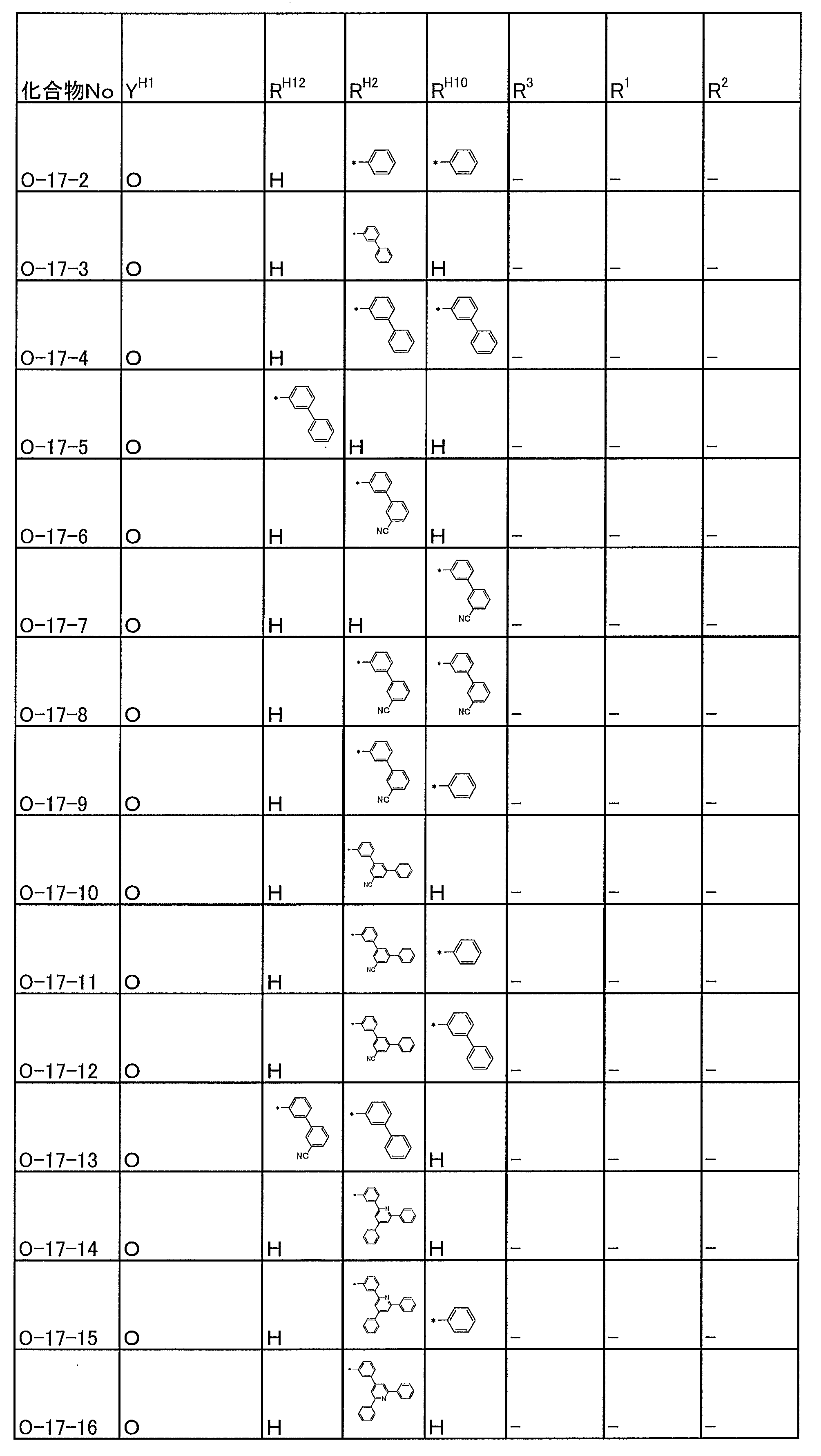
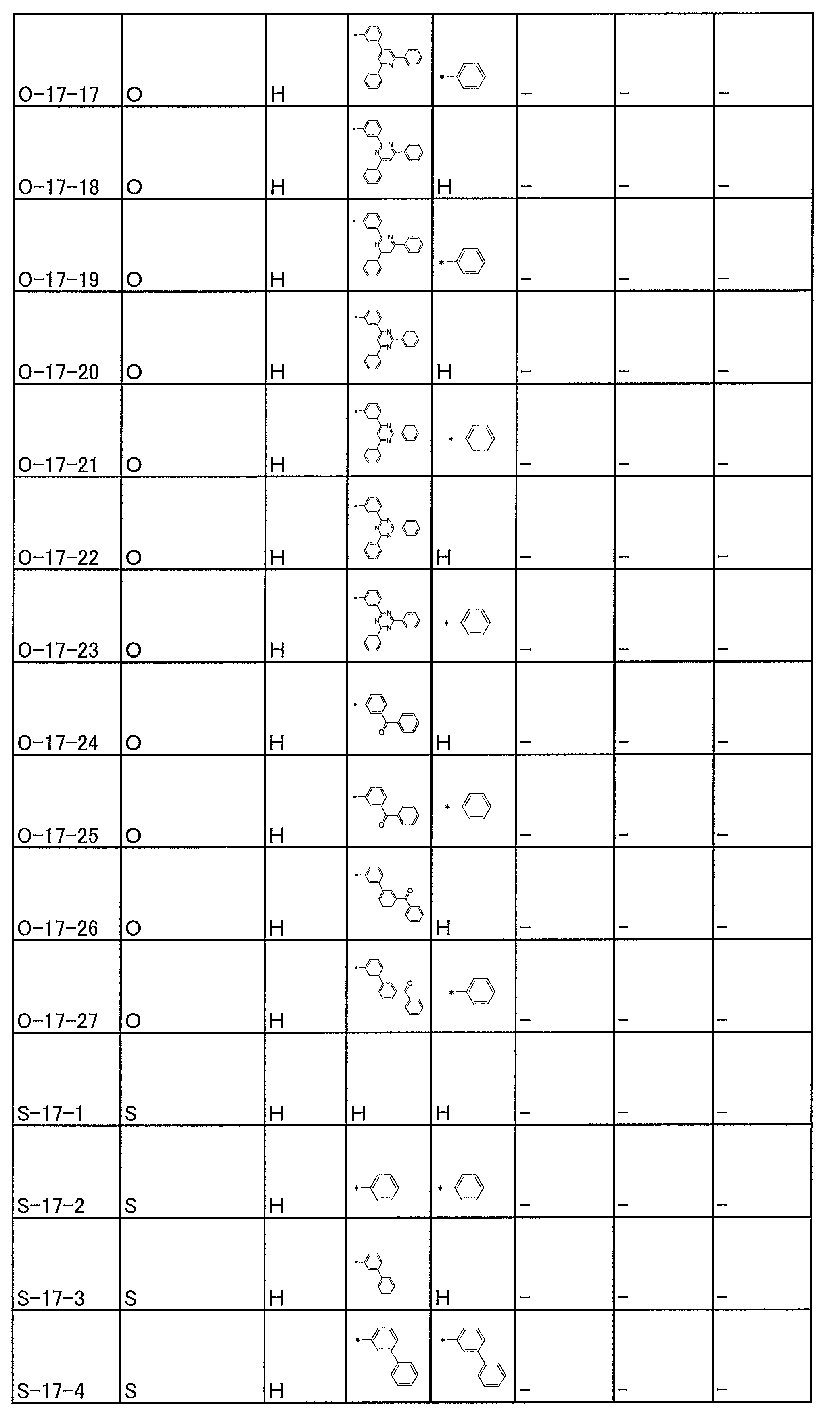

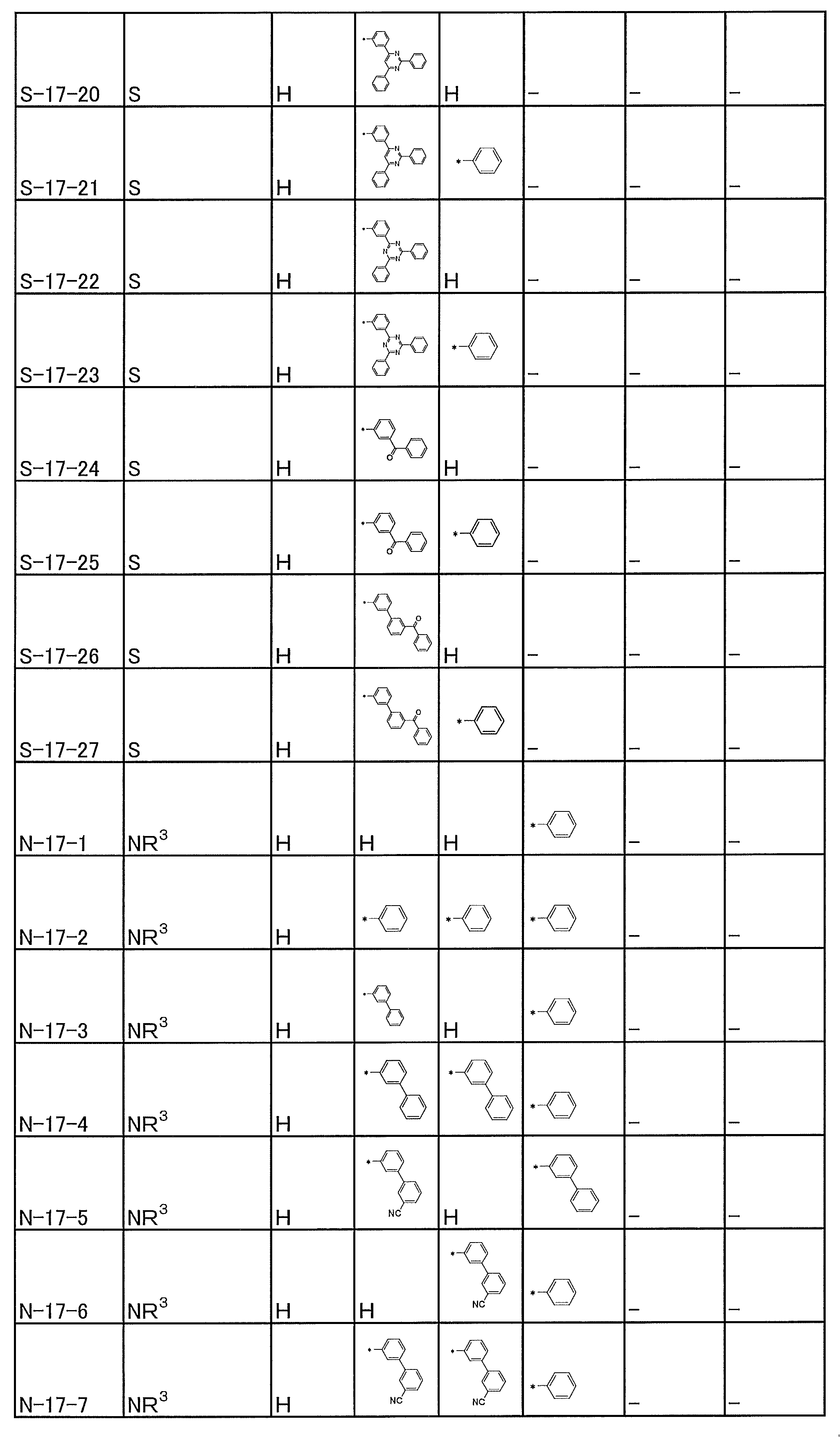
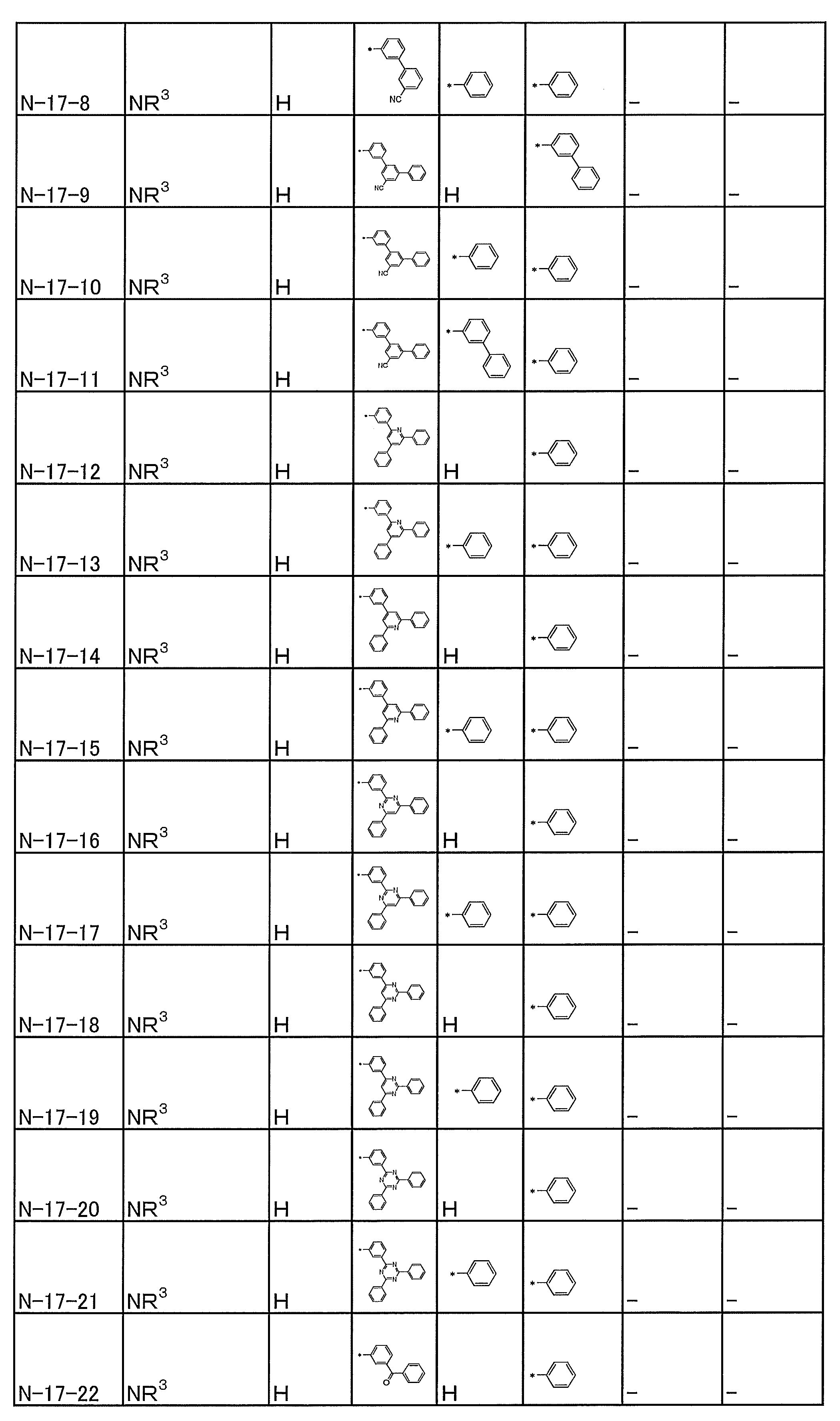
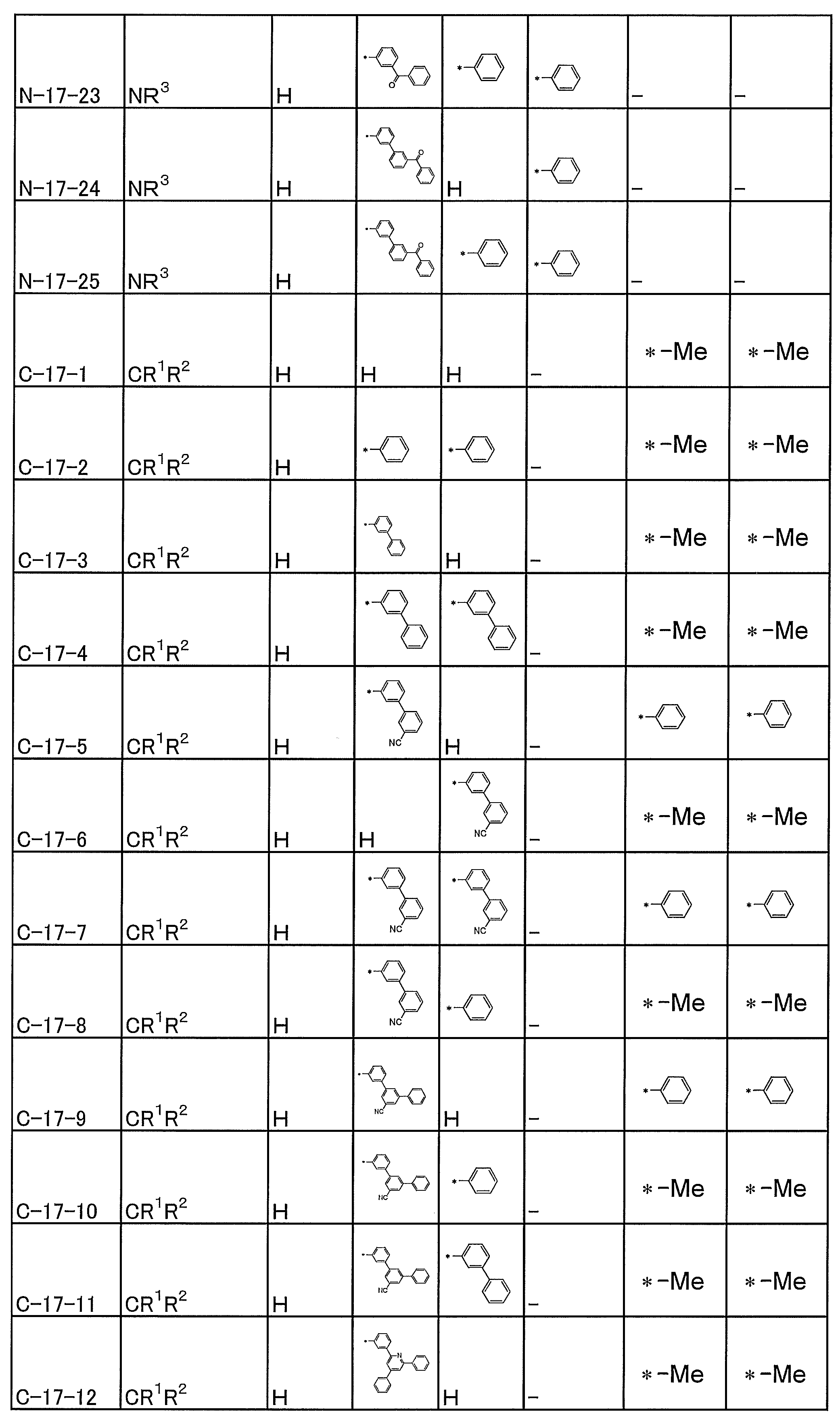
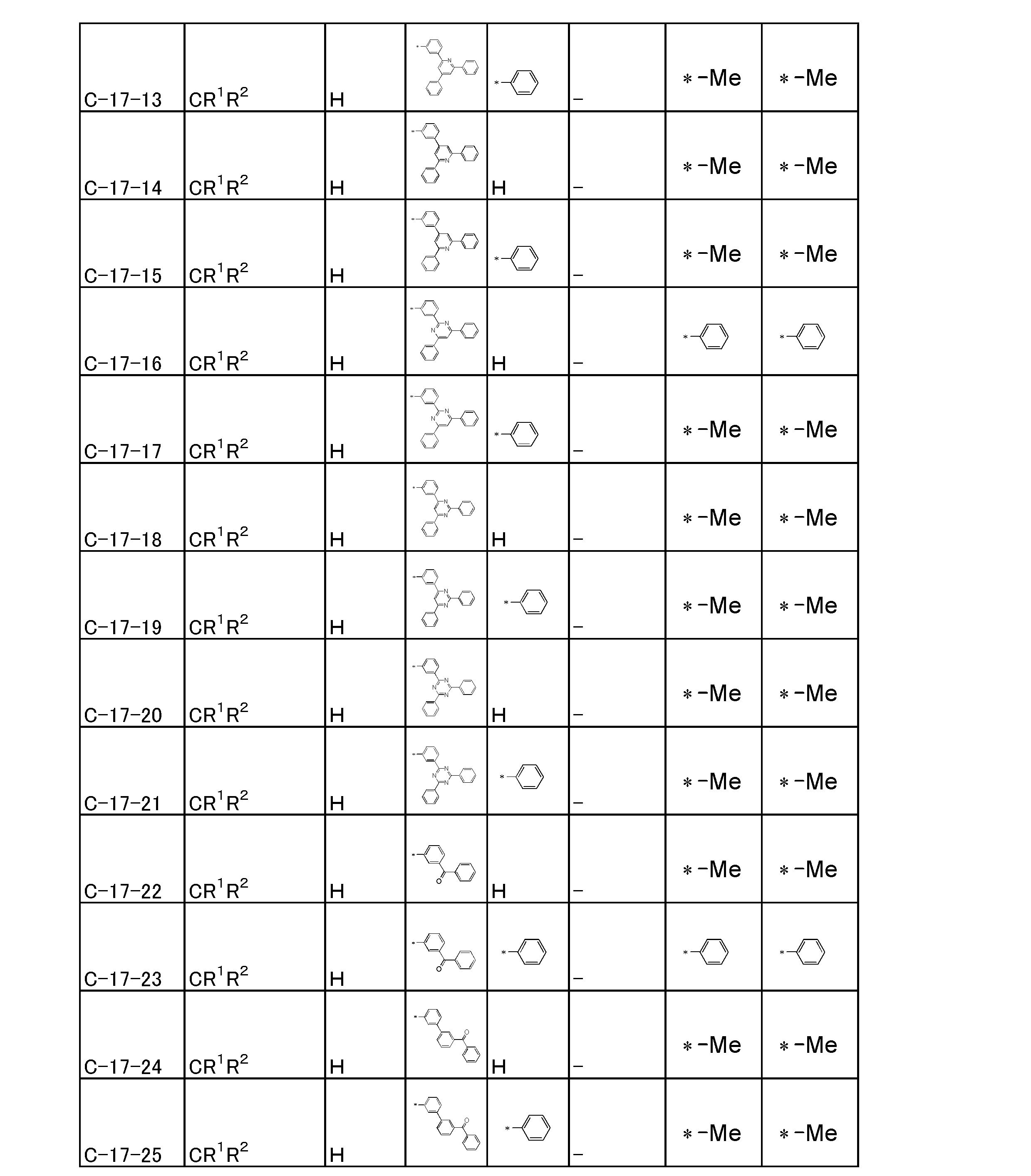
前記一般式(2)~(9)で表される化合物は、それぞれ以下のスキームによって好ましく合成することができる。但し、下記の合成スキームは合成の一例であり、別の公知の方法によっても合成することができる。
一般式(2)の合成ルート
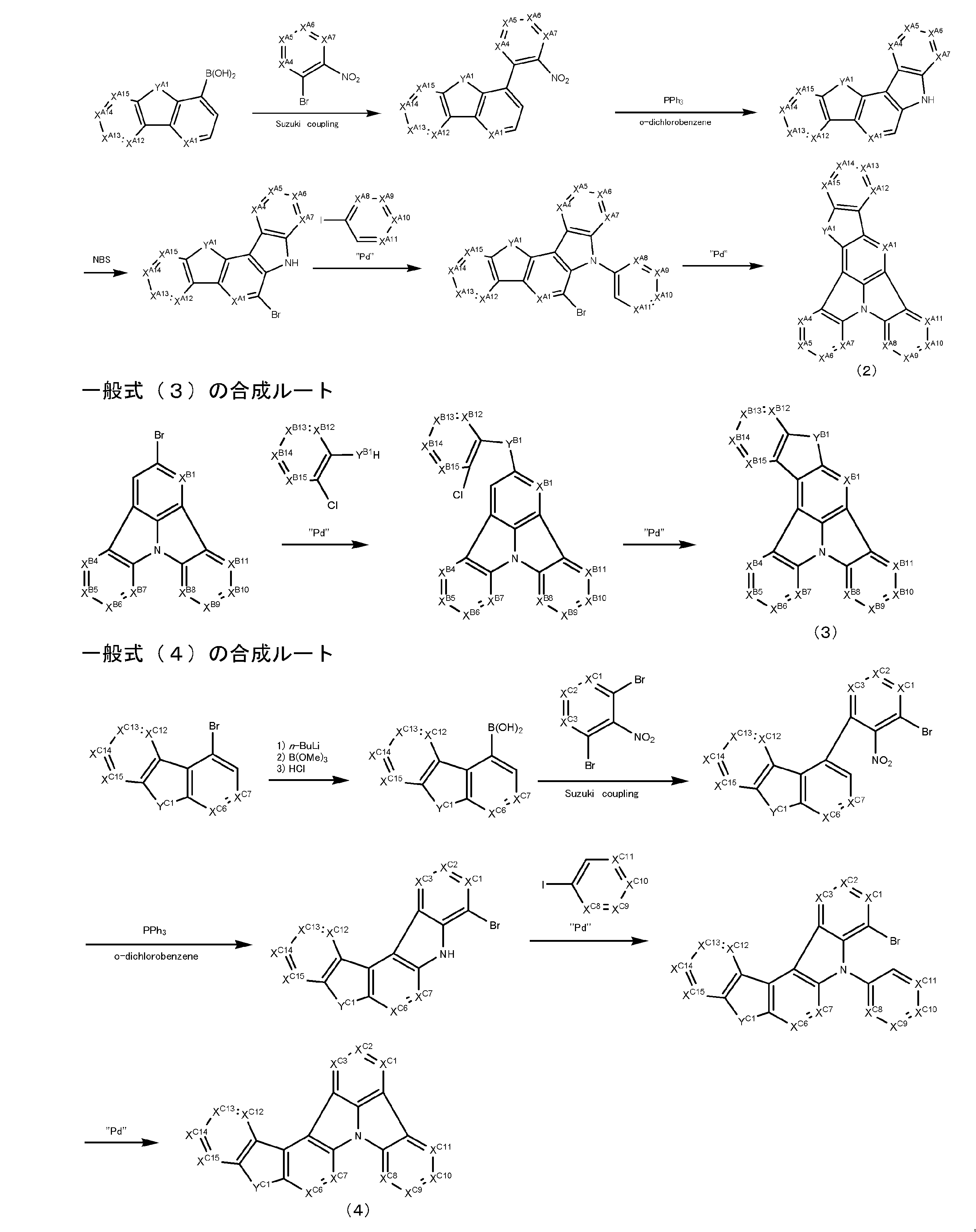
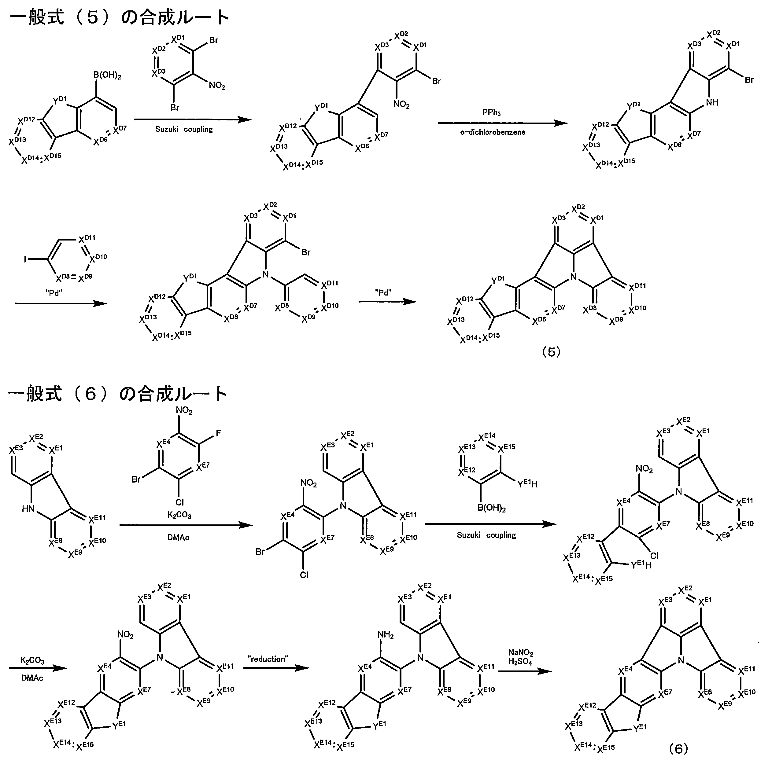
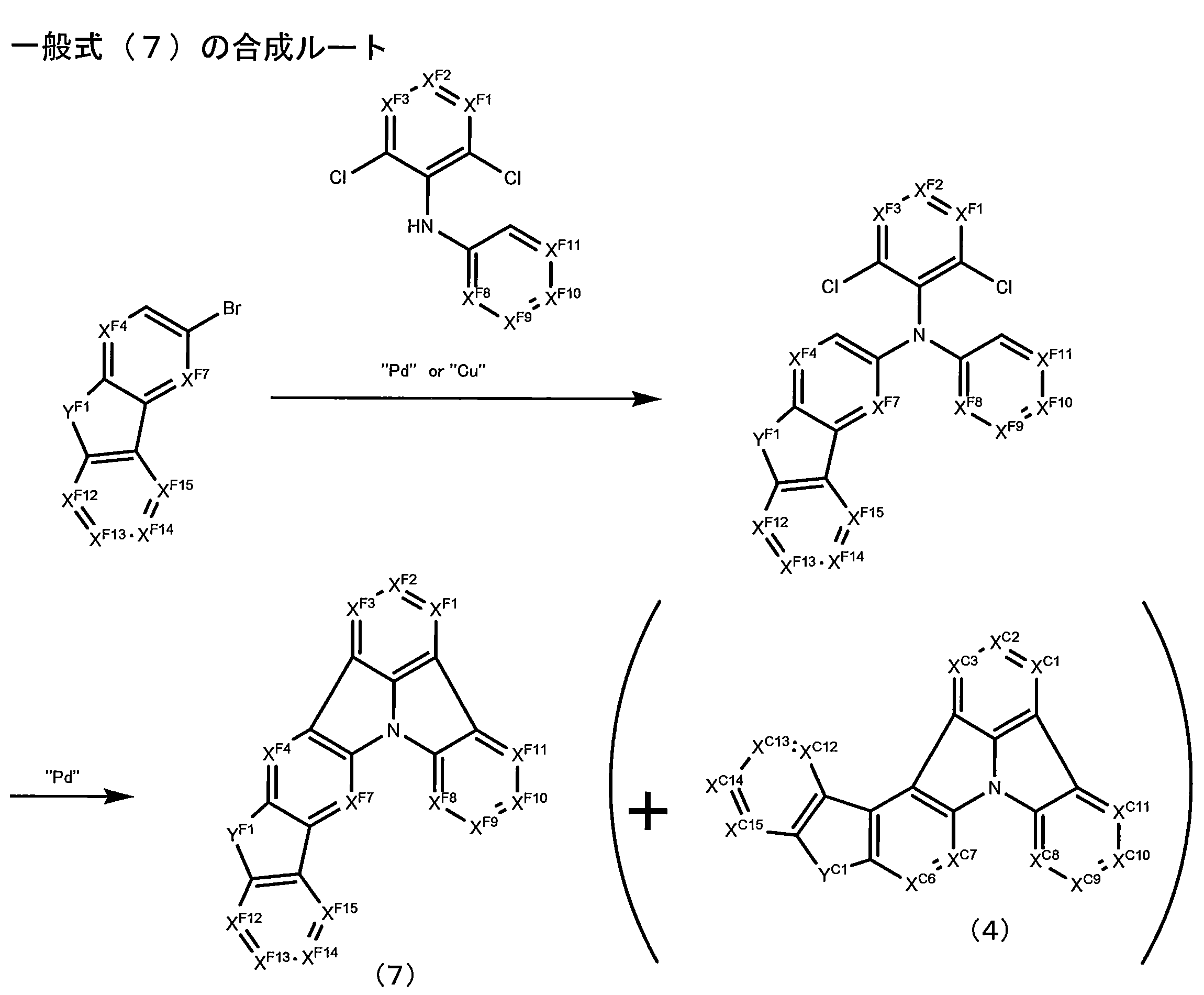
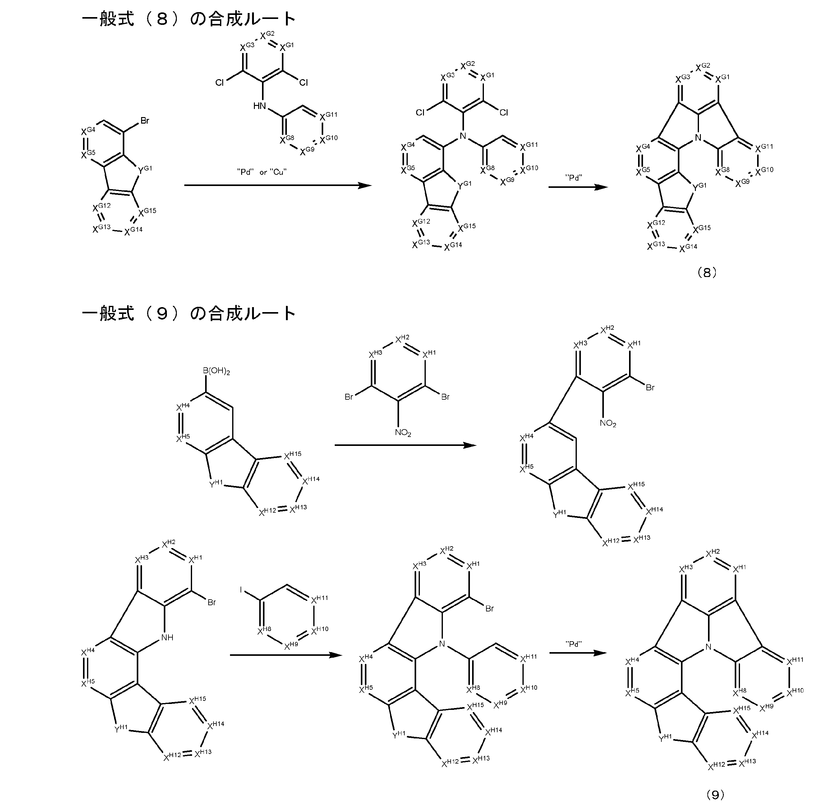
前記一般式(1)で表される化合物を発光層中に含有させる場合、前記一般式(1)で表される化合物は前記発光層の全質量に対して0.1~99質量%含ませることが好ましく、1~97質量%含ませることがより好ましく、10~96質量%含ませることが更に好ましい。前記一般式(1)で表される化合物を発光層以外の層に更に含有させる場合は、該発光層以外の層の全質量に対して50~100質量%含まれることが好ましく、85~100質量%含まれることがより好ましい。
本発明では、前記発光層に少なくとも一種の燐光発光材料を有することが好ましい。本発明では、前記燐光発光材料に加えて、発光材料として、蛍光発光材料や、発光層に含有される燐光発光材料とは異なる燐光発光材料を用いることができる。
これら蛍光発光材料や燐光発光材料については、例えば、特開2008-270736号公報の段落番号[0100]~[0164]、特開2007-266458号公報の段落番号[0088]~[0090]に詳述されており、これら公報の記載の事項を本発明に適用することができる。
これら燐光発光性金属錯体化合物は、発光層において、前記一般式(1)で表される化合物と共に含有されるのが好ましい。
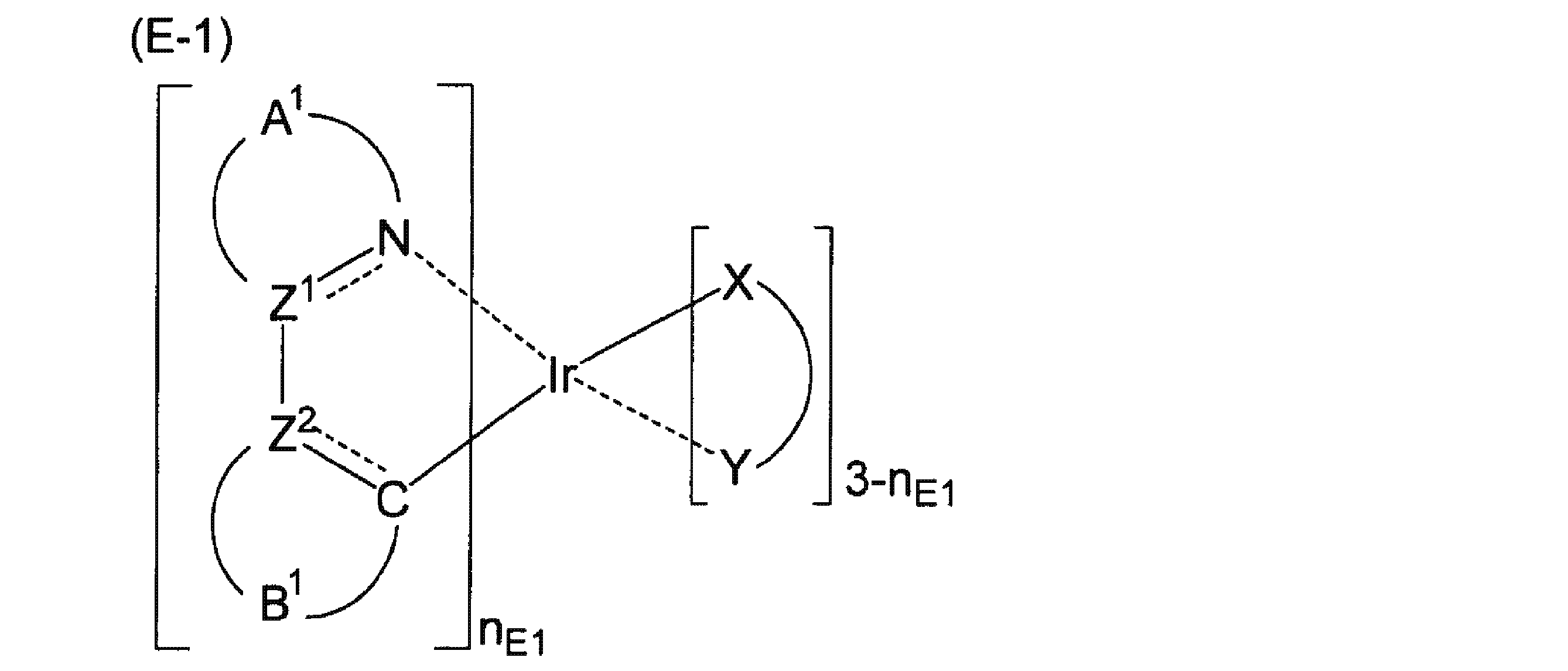
A1はZ1と窒素原子と共に5又は6員のヘテロ環を形成する原子群を表す。
B1はZ2と炭素原子と共に5又は6員環を形成する原子群を表す。
(X-Y)はモノアニオン性の二座配位子を表す。
nE1は1~3の整数を表す。
Z1及びZ2はそれぞれ独立に、炭素原子又は窒素原子を表す。Z1及びZ2として好ましくは炭素原子である。
錯体の安定性、発光波長制御及び発光量子収率の観点から、A1、Z1及び窒素原子で形成される5又は6員のヘテロ環として好ましくは、ピリジン環、ピラジン環、イミダゾール環、ピラゾール環であり、より好ましくはピリジン環、イミダゾール環、ピラジン環であり、更に好ましくはピリジン環、イミダゾール環であり、最も好ましくはピリジン環である。
前記置換基同士は連結して縮合環を形成していてもよく、形成される環としては、ベンゼン環、ピリジン環、ピラジン環、ピリダジン環、ピリミジン環、イミダゾール環、オキサゾール環、チアゾール環、ピラゾール環、チオフェン環、フラン環などが挙げられる。これら形成される環は置換基を有していてもよく、置換基としては前述の炭素原子上の置換基、窒素原子上の置換基が挙げられる。
錯体の安定性、発光波長制御及び発光量子収率の観点からB1、Z2及び炭素原子で形成される5又は6員環として好ましくは、ベンゼン環、ピリジン環、ピラジン環、イミダゾール環、ピラゾール環、チオフェン環であり、より好ましくはベンゼン環、ピリジン環、ピラゾール環であり、更に好ましくはベンゼン環、ピリジン環である。
炭素上の置換基として好ましくはアルキル基、ペルフルオロアルキル基、アリール基、ヘテロアリール基、ジアルキルアミノ基、ジアリールアミノ基、アルコキシ基、シアノ基、フッ素原子である。
また前記A1、Z1及び窒素原子で形成される5又は6員のヘテロ環の置換基と、前記B1、Z2及び炭素原子で形成される5又は6員環の置換基とが連結して、前述と同様の縮合環を形成していてもよい。
(X-Y)で表される二座のモノアニオン性配位子として好ましくは、下記一般式(L-1)で表される二座のモノアニオン配位子である。

RL3は水素原子、アルキル基、アリール基、又はヘテロアリール基を表す。
アルキル基(好ましくは炭素数1~10、より好ましくは炭素数1~6、更に好ましくは炭素数1~4であり、例えばメチル、エチル、イソプロピル、n-プロピル、tert-ブチル、イソブチル、n-ブチル、ネオペンチル、n-ペンチル、n-ヘキシル、シクロプロピル、シクロペンチル、シクロヘキシルなどが挙げられる)、アルケニル基(好ましくは炭素数2~8、より好ましくは炭素数2~5であり、例えばビニル等が挙げられる)、アリール基(炭素数6~30、より好ましくは炭素数6~20であり、例えばフェニル基、ナフチル基、アントラセニル基、テトラセニル基、ピレニル基、ペリレニル基、トリフェニレニル基、クリセニル基が挙げられる)、ヘテロアリール基(好ましくは炭素数4~30、より好ましくは炭素数4~20であり、例えばピリジン、ピラジン、ピリミジン、ピリダジン、トリアジン、チオフェン、フラン、オキサゾール、チアゾール、イミダゾール、ピラゾール、トリアゾール、オキサジアゾール、チアジアゾール等が挙げられる)、アルコキシ基(好ましくは炭素数1~8、より好ましくは炭素数1~5であり、例えばメトキシ基、エトキシ基、n-プロピルオキシ基、iso-プロピルオキシ基等が挙げられる)、フェノキシ基、ハロゲン原子(好ましくはフッ素原子)、シリル基(好ましくは炭素数4~30、より好ましくは炭素数4~20であり、トリメチルシリル基、トリエチルシリル基、トリフェニルシリル基などが挙げられる)、アミノ基(好ましくは炭素数2~60、より好ましくは炭素数2~40であり、ジメチルアミノ基、ジエチルアミノ基、ジフェニルアミノ基等が挙げられる)、シアノ基又はこれらを組み合わせて成る基を表し、複数の置換基Z'は互いに結合してアリール環を形成してもよい。複数の置換基Z'が互いに結合して形成するアリール環としては、フェニル環、ピリジン環等が挙げられ、フェニル環が好ましい。
RL1及びRL2で表されるアルキル基として、好ましくは総炭素原子数1~8のアルキル基であり、より好ましくは総炭素原子数1~5のアルキル基であり、例えばメチル基、エチル基、n-プロピル基、iso-プロピル基、iso-ブチル基、t-ブチル基、n-ブチル基、シクロヘキシル基等が挙げられ、メチル基、エチル基、iso-ブチル基、又はt-ブチル基が好ましく、メチル基が特に好ましい。
次に一般式(E-2)について説明する。
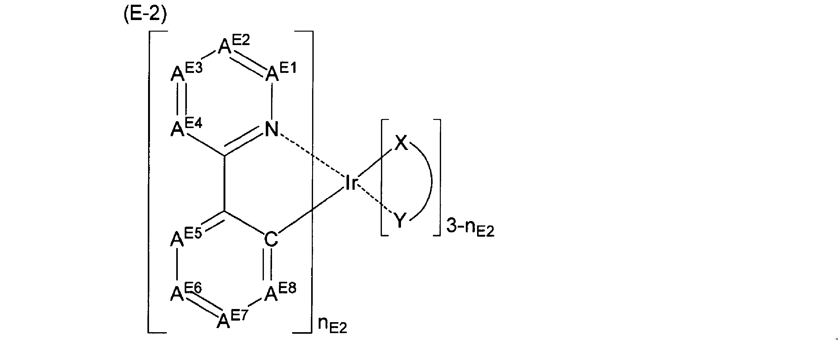
REは水素原子又は置換基を表す。
(X-Y)はモノアニオン性の二座配位子を表す。
nE2は1~3の整数を表す。
AE1~AE4として好ましくはC-REであり、AE1~AE4がC-REである場合に、AE3のREとして好ましくは水素原子、アルキル基、アリール基、アミノ基、アルコキシ基、アリールオキシ基、フッ素原子、又はシアノ基であり、より好ましくは水素原子、アルキル基、アミノ基、アルコキシ基、アリールオキシ基、又はフッ素原子であり、特に好ましく水素原子、又はフッ素原子であり、AE1、AE2及びAE4のREとして好ましくは水素原子、アルキル基、アリール基、アミノ基、アルコキシ基、アリールオキシ基、フッ素原子、又はシアノ基であり、より好ましくは水素原子、アルキル基、アミノ基、アルコキシ基、アリールオキシ基、又はフッ素原子であり、特に好ましく水素原子である。
(X-Y)、及びnE2は一般式(E-1)における(X-Y)、及びnE1と同義であり好ましい範囲も同様である。
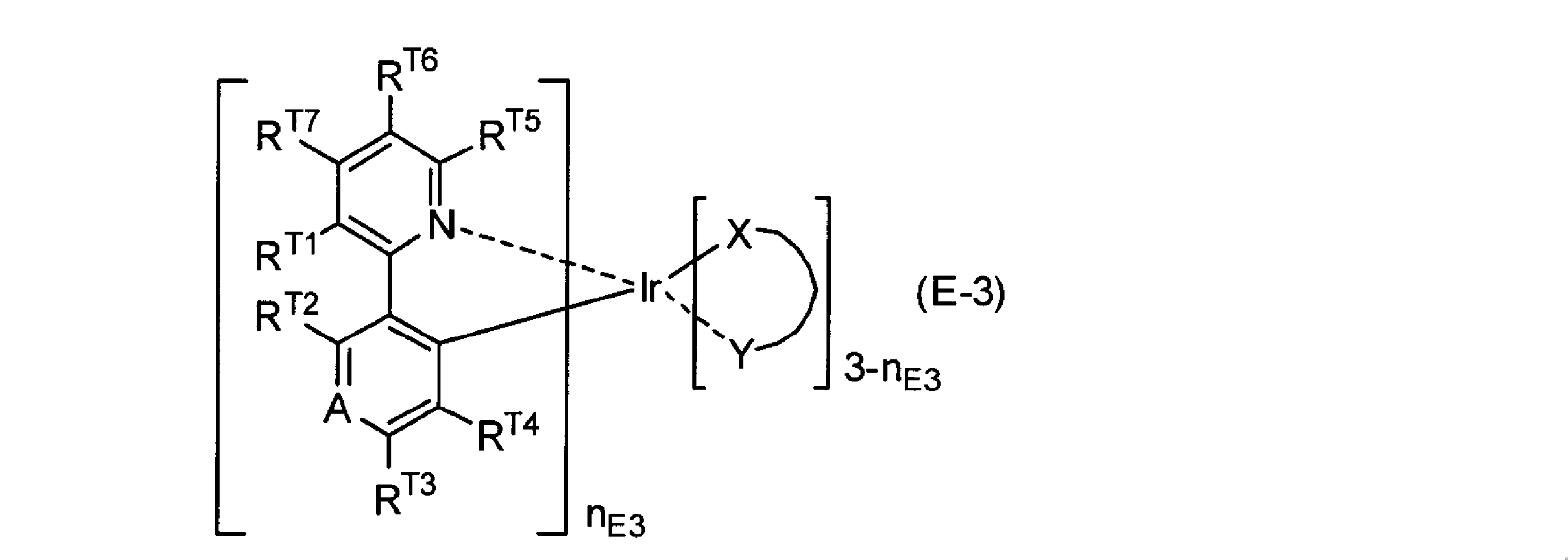
AはCR'又は窒素原子を表し、R'は水素原子、アルキル基、シクロアルキル基、アルケニル基、アルキニル基、-CN、ペルフルオロアルキル基、トリフルオロビニル基、-CO2R、-C(O)R、-NR2、-NO2、-OR、ハロゲン原子、アリール基又はヘテロアリール基を表し、更に置換基Zを有していてもよい。Rはそれぞれ独立に、水素原子、アルキル基、ペルハロアルキル基、アルケニル基、アルキニル基、ヘテロアルキル基、アリール基又はヘテロアリール基を表す。
RT1~RT7、及びR'は、任意の2つが互いに結合して縮合4~7員環を形成してもよく、該縮合4~7員環は、シクロアルキル、アリール又はヘテロアリールであり、該縮合4~7員環は更に置換基Zを有していてもよい。これらのうち、RT1とRT7、又はRT5とRT6で縮環してベンゼン環を形成する場合が好ましく、RT5とRT6で縮環してベンゼン環を形成する場合が特に好ましい。
Zはそれぞれ独立に、ハロゲン原子、-R"、-OR"、-N(R")2、-SR"、-C(O)R"、-C(O)OR"、-C(O)N(R")2、-CN、-NO2、-SO2、-SOR"、-SO2R"、又は-SO3R"を表し、R"はそれぞれ独立に、水素原子、アルキル基、ペルハロアルキル基、アルケニル基、アルキニル基、ヘテロアルキル基、アリール基又はヘテロアリール基を表す。
(X-Y)は、モノアニオン性の二座配位子を表す。nE3は1~3の整数を表す。
シクロアルキル基としては、置換基を有していてもよく、飽和であっても不飽和であってもよく、置換してもよい基としては、前述の置換基Zを挙げることができる。RT1~RT7、及びR'で表されるシクロアルキル基として、好ましくは環員数4~7のシクロアルキル基であり、より好ましくは総炭素原子数5~6のシクロアルキル基であり、例えばシクロペンチル基、シクロヘキシル基等が挙げられる。
RT1~RT7、及びR'で表されるアルケニル基としては好ましくは炭素数2~30、より好ましくは炭素数2~20、特に好ましくは炭素数2~10であり、例えばビニル、アリル、1-プロペニル、1-イソプロペニル、1-ブテニル、2-ブテニル、3-ペンテニルなどが挙げられる。
RT1~RT7、及びR'で表されるアルキニル基としては、好ましくは炭素数2~30、より好ましくは炭素数2~20、特に好ましくは炭素数2~10であり、例えばエチニル、プロパルギル、1-プロピニル、3-ペンチニルなどが挙げられる。
またAがCR'を表すと共に、RT1~RT7、及びR'のうち、0~2つがアルキル基又はフェニル基で、残りが全て水素原子である場合が特に好ましく、RT1~RT7、及びR'のうち、0~2つがアルキル基で、残りが全て水素原子である場合が特に好ましい。
(X-Y)は、一般式(E-1)における(X-Y)と同義であり好ましい範囲も同様である。
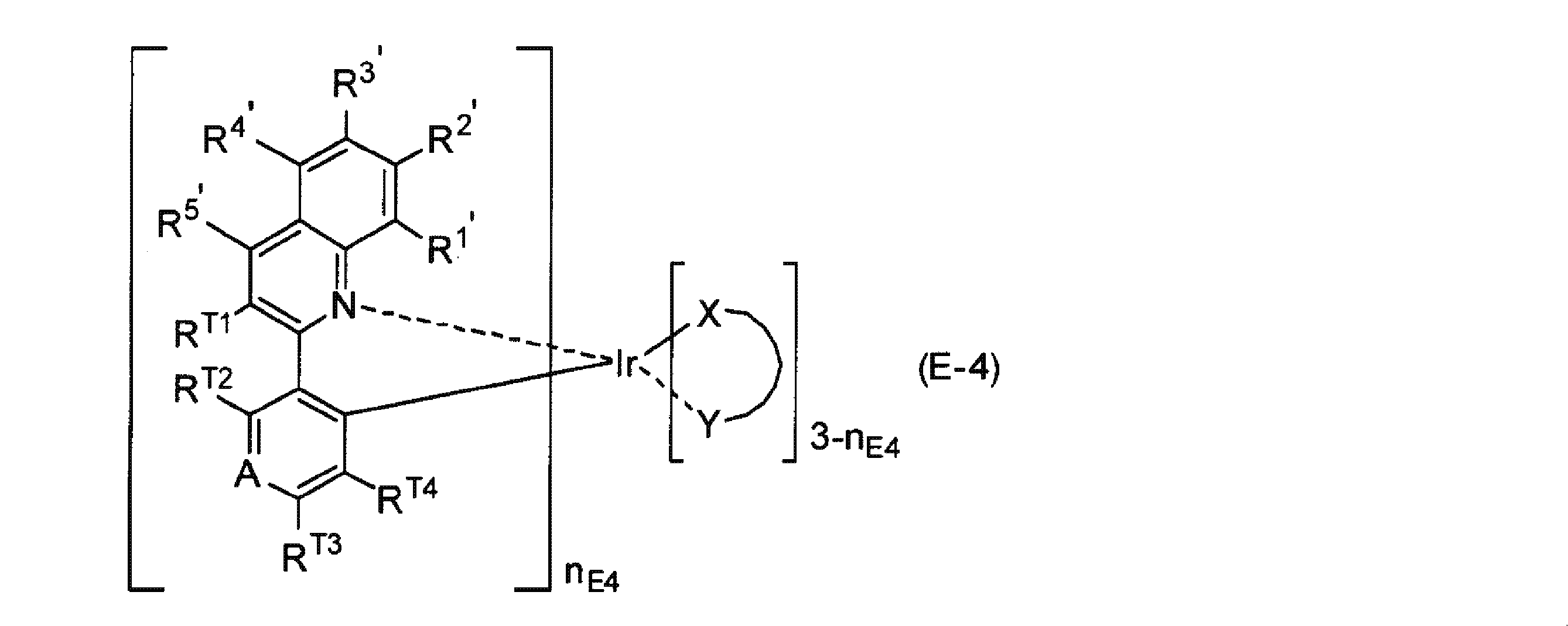
R1'~R5'は、任意の2つが互いに結合して縮合4~7員環を形成してもよく、該縮合4~7員環は、シクロアルキル、アリール又はヘテロアリールであり、該縮合4~7員環は更に置換基Zを有していてもよい。
Zはそれぞれ独立に、ハロゲン原子、-R"、-OR"、-N(R")2、-SR"、-C(O)R"、-C(O)OR"、-C(O)N(R")2、-CN、-NO2、-SO2、-SOR"、-SO2R"、又は-SO3R"を表し、R"はそれぞれ独立に、水素原子、アルキル基、ペルハロアルキル基、アルケニル基、アルキニル基、ヘテロアルキル基、アリール基又はヘテロアリール基を表す。
また、R1'~R5'における好ましい範囲は、一般式(E-3)におけるRT1~RT7、R'と同様である。またAがCR'を表すと共に、RT1~RT4、R'、及びR1'~R5'のうち、0~2つがアルキル基又はフェニル基で残りが全て水素原子である場合が特に好ましく、RT1~RT4、R'、及びR1'~R5'のうち、0~2つがアルキル基で残りが全て水素原子である場合が更に好ましい。

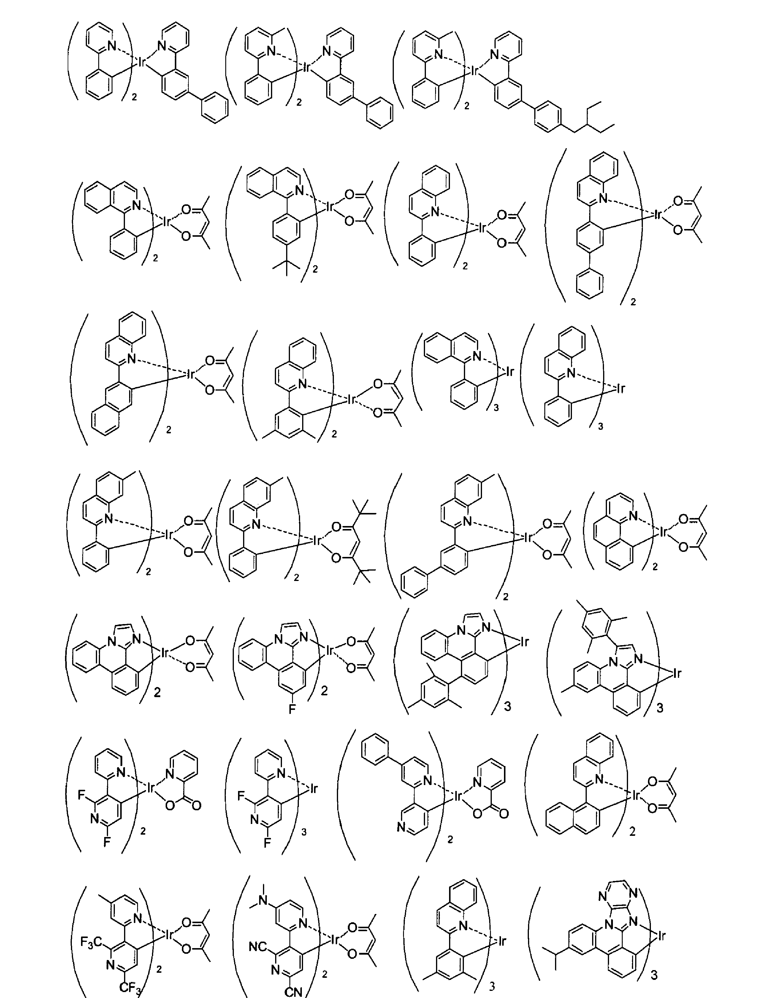

前記一般式(1)で表される化合物以外のその他の前記発光層に用いることのできるホスト材料としては、例えば、以下の構造を部分構造に持つ化合物を挙げることができる。
芳香族炭化水素、ピロール、インドール、カルバゾール、アザインドール、インドロカルバゾール、アザカルバゾール、トリアゾール、オキサゾール、オキサジアゾール、ピラゾール、イミダゾール、チオフェン、ポリアリールアルカン、ピラゾリン、ピラゾロン、フェニレンジアミン、アリールアミン、アミノ置換カルコン、スチリルアントラセン、ヒドラゾン、スチルベン、シラザン、芳香族第三級アミン化合物、スチリルアミン化合物、ポルフィリン系化合物、ポリシラン系化合物、ポリ(N-ビニルカルバゾール)、アニリン系共重合体、チオフェンオリゴマー、ポリチオフェン等の導電性高分子オリゴマー、有機シラン、カーボン膜、ピリジン、ピリミジン、トリアジン、フルオレノン、アントラキノジメタン、アントロン、ジフェニルキノン、チオピランジオキシド、カルボジイミド、フルオレニリデンメタン、ジスチリルピラジン、フッ素置換芳香族化合物、ナフタレンペリレン等の複素環テトラカルボン酸無水物、フタロシアニン、8-キノリノ-ル誘導体の金属錯体やメタルフタロシアニン、ベンゾオキサゾ-ルやベンゾチアゾ-ルを配位子とする金属錯体に代表される各種金属錯体及びそれらの誘導体(置換基や縮環を有していてもよい)等を挙げることができる。
本発明の有機電界発光素子は、前記発光層以外のその他の層を有していてもよい。
前記有機層が有していてもよい前記発光層以外のその他の有機層として、正孔注入層、正孔輸送層、ブロック層(正孔ブロック層、電子ブロック層、励起子ブロック層など)、電子輸送層などが挙げられる。前記具体的な層構成として、下記が挙げられるが本発明はこれらの構成に限定されるものではない。
・陽極/正孔輸送層/発光層/電子輸送層/陰極、
・陽極/正孔輸送層/発光層/ブロック層/電子輸送層/陰極、
・陽極/正孔輸送層/発光層/ブロック層/電子輸送層/電子注入層/陰極、
・陽極/正孔注入層/正孔輸送層/発光層/ブロック層/電子輸送層/陰極、
・陽極/正孔注入層/正孔輸送層/発光層/電子輸送層/電子注入層/陰極、
・陽極/正孔注入層/正孔輸送層/発光層/ブロック層/電子輸送層/電子注入層/陰極、
・陽極/正孔注入層/正孔輸送層/ブロック層/発光層/ブロック層/電子輸送層/電子注入層/陰極。
本発明の有機電界発光素子は、(A)前記陽極と前記発光層との間に好ましく配置される有機層を少なくとも一層含むことが好ましい。前記(A)前記陽極と前記発光層との間に好ましく配置される有機層としては、陽極側から正孔注入層、正孔輸送層、電子ブロック層を挙げることができる。
本発明の有機電界発光素子は、(B)前記陰極と前記発光層との間に好ましく配置される有機層少なくとも一層含むことが好ましい。前記(B)前記陰極と前記発光層との間に好ましく配置される有機層としては、陰極側から電子注入層、電子輸送層、正孔ブロック層を挙げることができる。
具体的には、本発明の有機電界発光素子の好ましい態様の一例は、図1に記載される態様であり、前記有機層として、陽極側3から正孔注入層4、正孔輸送層5、発光層6、正孔ブロック層7及び電子輸送層8がこの順に積層されている態様である。
以下、これら本発明の有機電界発光素子が有していてもよい前記発光層以外のその他の層について、説明する。
まず、(A)前記陽極と前記発光層との間に好ましく配置される有機層について説明する。
正孔注入層、正孔輸送層は、陽極又は陽極側から正孔を受け取り陰極側に輸送する機能を有する層である。これらの層に用いる正孔注入材料、正孔輸送材料は低分子化合物であっても高分子化合物であってもよい。
正孔注入層、正孔輸送層については、特開2008-270736号公報の段落番号〔0165〕~〔0167〕に記載の事項を本発明に適用することができる。
電子ブロック層は、陰極側から発光層に輸送された電子が、陽極側に通りぬけることを防止する機能を有する層である。本発明において、発光層と陽極側で隣接する有機層として、電子ブロック層を設けることができる。
電子ブロック層を構成する有機化合物の例としては、例えば前述の正孔輸送材料として挙げたものが適用できる。
電子ブロック層の厚さとしては、1nm~500nmであるのが好ましく、3nm~200nmであるのがより好ましく、5nm~100nmであるのが更に好ましい。
電子ブロック層は、上述した材料の一種又は二種以上からなる単層構造であってもよいし、同一組成又は異種組成の複数層からなる多層構造であってもよい。
電子ブロック層を構成する有機化合物の膜状態でのT1エネルギーは、発光層で生成する励起子のエネルギー移動を防止し、発光効率を低下させないために、発光材料のT1エネルギーよりも高いことが好ましい。
〔一般式(M-1)で表される化合物〕
本発明の有機電界発光素子は、前記(A)陽極と前記発光層との間に好ましく配置される有機層に特に好ましく用いられる材料として、少なくとも一種の下記一般式(M-1)で表される化合物を挙げることができる。
前記一般式(M-1)で表される化合物が含有される、発光層と陽極の間の発光層に隣接する有機層は、電子ブロック層又は正孔輸送層であることがより好ましい。
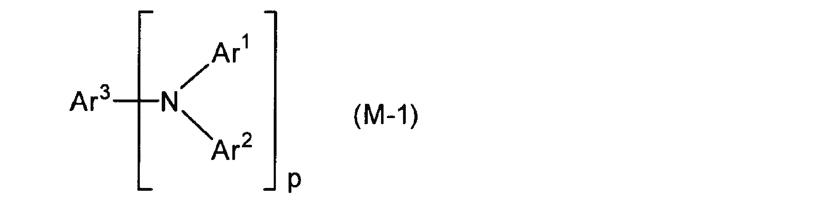
Ar3はP価のアルキル、アリール、ヘテロアリール、アリールアミノを表し、更に置換基Zを有していてもよい。
Zはそれぞれ独立に、ハロゲン原子、-R"、-OR"、-N(R")2、-SR"、-C(O)R"、-C(O)OR"、-C(O)N(R")2、-CN、-NO2、-SO2、-SOR"、-SO2R"、又は-SO3R"を表し、R"はそれぞれ独立に、水素原子、アルキル基、ペルハロアルキル基、アルケニル基、アルキニル基、ヘテロアルキル基、アリール基又はヘテロアリール基を表す。
pは1~4の整数であり、pが2以上のときAr1及びAr2はそれぞれ同一でも異なっていてもよい。
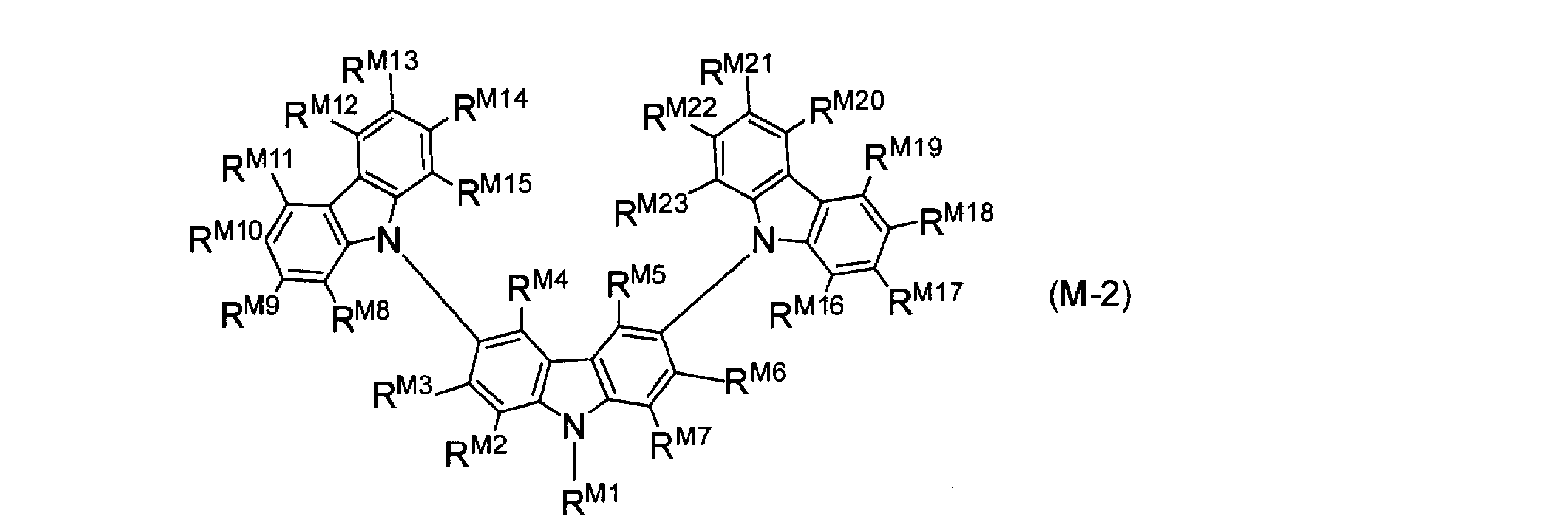
RM2~RM23はそれぞれ独立に、水素原子、アルキル基、アリール基、ヘテロアリール基、アルコキシ基、アリールオキシ基、アミノ基、シリル基、シアノ基、ニトロ基、又はフッ素原子を表す。
RM4、RM5、RM11、RM12、RM19及びRM20として好ましくは、水素原子、置換基Zを有していてもよいアルキル基若しくはアリール基、又はフッ素原子であり、更に好ましくは水素原子である。
RM3、RM6、RM9、RM14、RM17及びRM22として好ましくは、水素原子、置換基Zを有していてもよいアルキル基若しくはアリール基、フッ素原子、又はシアノ基であり、より好ましくは水素原子、又は置換基Zを有していてもよいアルキル基であり、更に好ましくは水素原子である。
RM10、RM13、RM18及びRM21として好ましくは、水素原子、置換基Zを有していてもよいアルキル基、アリール基、ヘテロアリール基若しくはアミノ基、ニトロ基、フッ素原子、又はシアノ基であり、より好ましくは水素原子、置換基Zを有していてもよいアルキル基若しくはアリール基、ニトロ基、フッ素原子、又はシアノ基であり、更に好ましくは水素原子、又は置換基Zを有していてもよいアルキル基である。アルキル基が置換基を有する場合の置換基としては、フッ素原子が好ましく、置換基Zを有していてもよいアルキル基の炭素数は好ましくは1~6であり、より好ましくは1~4である。
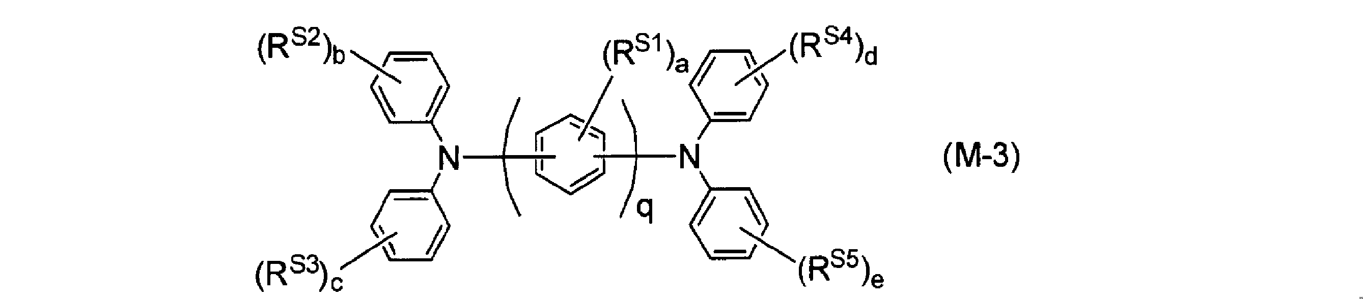
aは0~4の整数を表し、複数のRS1が存在するとき、それらは同一でも異なっていてもよく、互いに結合して環を形成してもよい。b~eはそれぞれ独立に0~5の整数を表し、それぞれ複数のRS2~RS5が存在するとき、それらは同一でも異なっていてもよく、任意の2つが結合し環を形成してもよい。
qは1~5の整数であり、qが2以上のとき複数のRS1は同一でも異なっていてもよく、互いに結合して環を形成していてもよい。
シクロアルキル基としては、置換基を有していてもよく、飽和であっても不飽和であってもよく、置換してもよい基としては、前述の置換基Zを挙げることができる。RS1~RS5で表されるシクロアルキル基として、好ましくは環員数4~7のシクロアルキル基であり、より好ましくは総炭素原子数5~6のシクロアルキル基であり、例えばシクロペンチル基、シクロヘキシル基等が挙げられる。
RS1~RS5で表されるアルケニル基としては好ましくは炭素数2~30、より好ましくは炭素数2~20、特に好ましくは炭素数2~10であり、例えばビニル、アリル、1-プロペニル、1-イソプロペニル、1-ブテニル、2-ブテニル、3-ペンテニルなどが挙げられる。
RS1~RS5で表されるアルキニル基としては、好ましくは炭素数2~30、より好ましくは炭素数2~20、特に好ましくは炭素数2~10であり、例えばエチニル、プロパルギル、1-プロピニル、3-ペンチニルなどが挙げられる。
また、前記一般式(M-1)で表される化合物を、複数の有機層に用いる場合はそれぞれの層において、上記の範囲で含有することが好ましい。
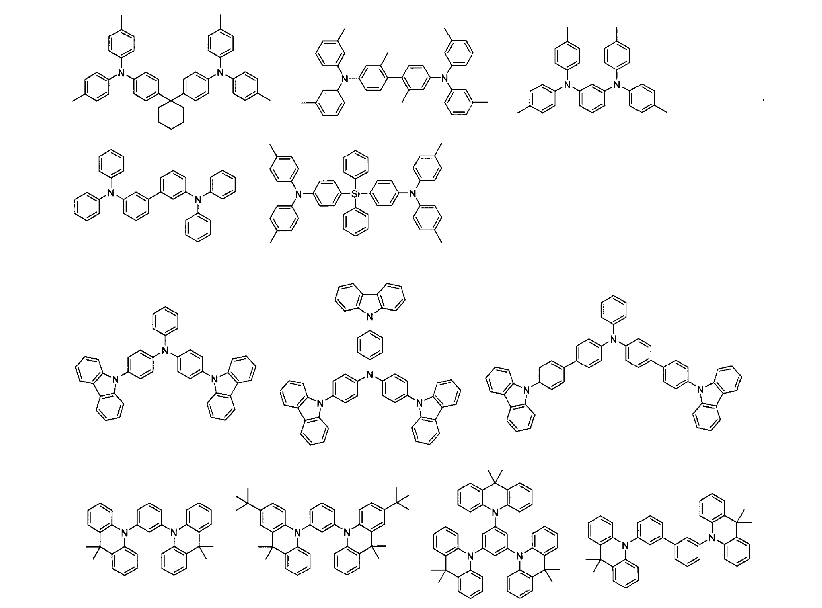
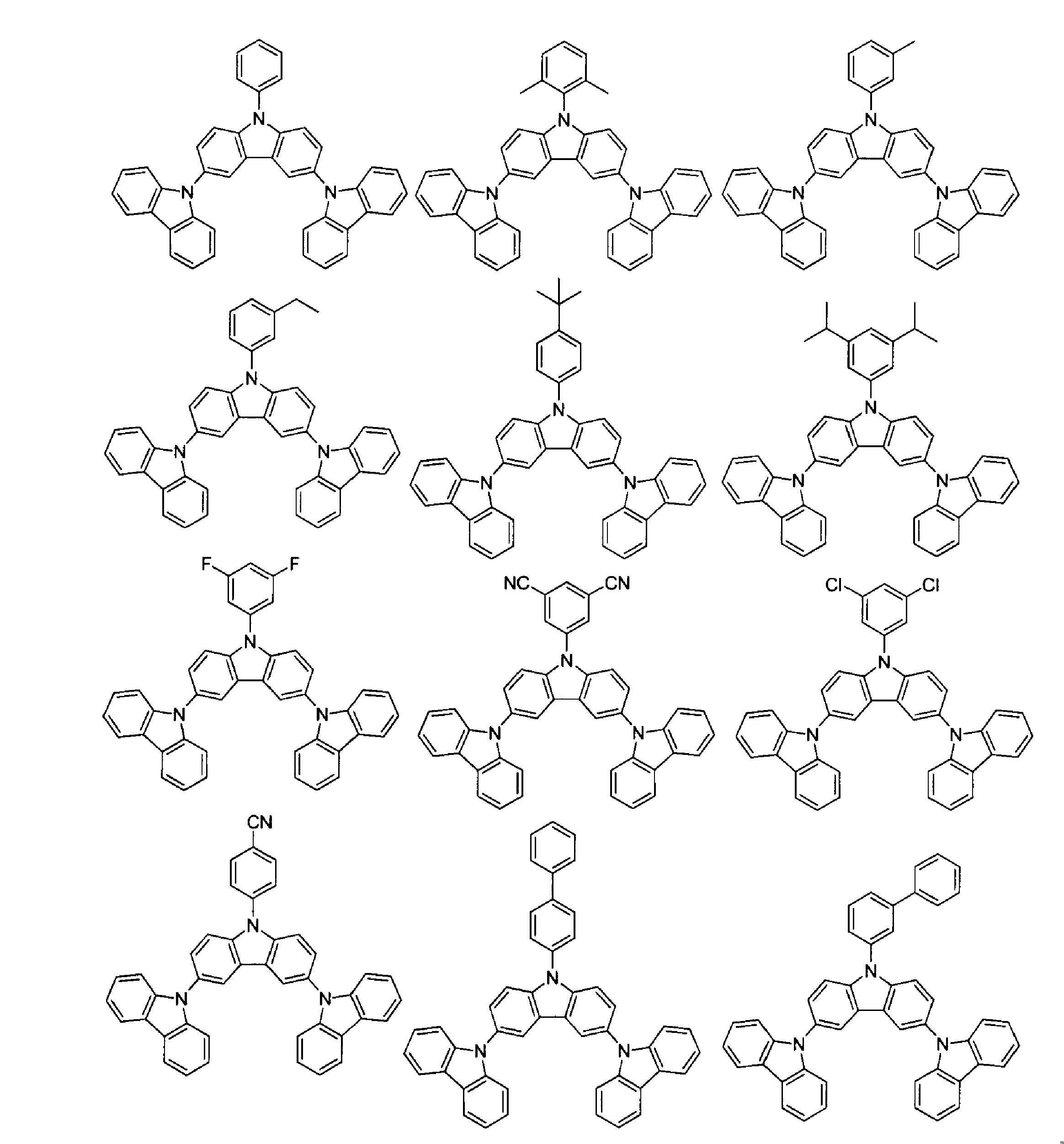
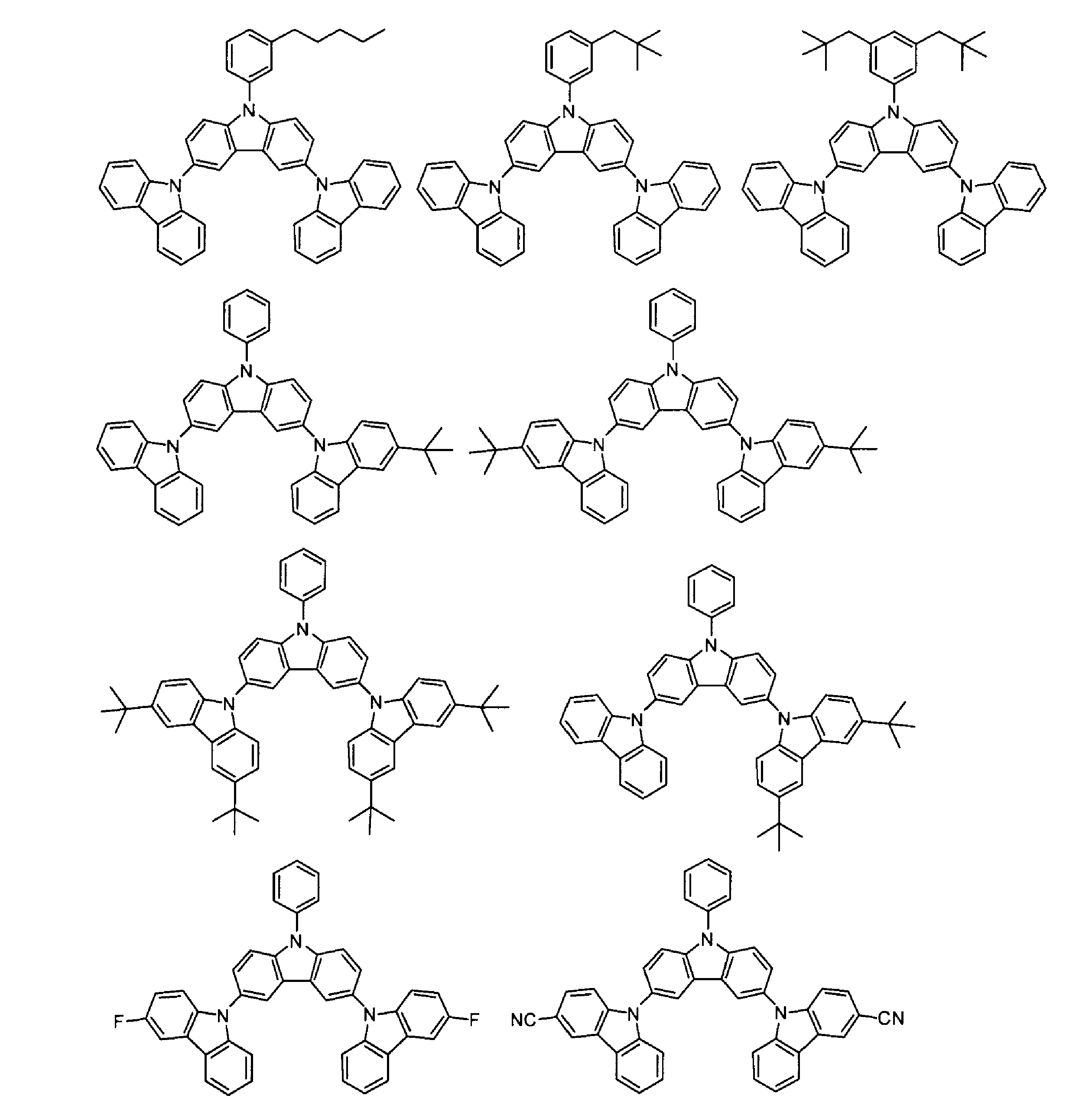

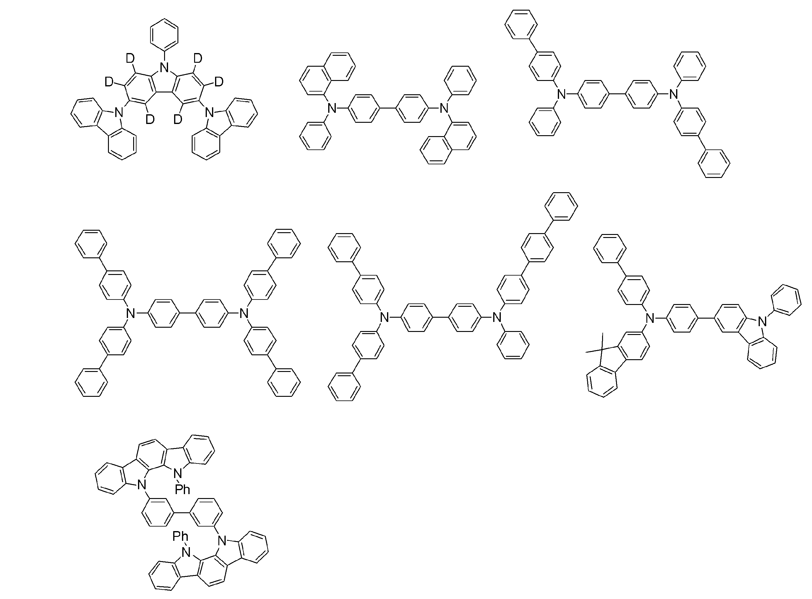
次に、前記(B)陰極と前記発光層との間に好ましく配置される有機層について説明する。
電子注入層、電子輸送層は、陰極又は陰極側から電子を受け取り陽極側に輸送する機能を有する層である。これらの層に用いる電子注入材料、電子輸送材料は低分子化合物であっても高分子化合物であってもよい。
電子輸送材料としては、前記一般式(1)で表される化合物を用いることができる。その他の電子輸送材料としては、ピリジン誘導体、キノリン誘導体、ピリミジン誘導体、ピラジン誘導体、フタラジン誘導体、フェナントロリン誘導体、トリアジン誘導体、トリアゾール誘導体、オキサゾール誘導体、オキサジアゾール誘導体、イミダゾール誘導体、ベンゾイミダゾール誘導体、イミダゾピリジン誘導体、フルオレノン誘導体、アントラキノジメタン誘導体、アントロン誘導体、ジフェニルキノン誘導体、チオピランジオキシド誘導体、カルボジイミド誘導体、フルオレニリデンメタン誘導体、ジスチリルピラジン誘導体、ナフタレン、ペリレン等の芳香環テトラカルボン酸無水物、フタロシアニン誘導体、8-キノリノール誘導体の金属錯体やメタルフタロシアニン、ベンゾオキサゾールやベンゾチアゾールを配位子とする金属錯体に代表される各種金属錯体、シロールに代表される有機シラン誘導体、ナフタレン、アントラセン、フェナントレン、トリフェニレン、ピレン等の縮環炭化水素化合物等をから選ばれることが好ましく、ピリジン誘導体、ベンゾイミダゾール誘導体、イミダゾピリジン誘導体、金属錯体、縮環炭化水素化合物のいずれかであることがより好ましい。
電子輸送層の厚さとしては、1nm~500nmであるのが好ましく、5nm~200nmであるのがより好ましく、10nm~100nmであるのが更に好ましい。また、電子注入層の厚さとしては、0.1nm~200nmであるのが好ましく、0.2nm~100nmであるのがより好ましく、0.5nm~50nmであるのが更に好ましい。
電子注入層、電子輸送層は、上述した材料の1種又は2種以上からなる単層構造であってもよいし、同一組成又は異種組成の複数層からなる多層構造であってもよい。
正孔ブロック層は、陽極側から発光層に輸送された正孔が、陰極側に通りぬけることを防止する機能を有する層である。本発明において、発光層と陰極側で隣接する有機層として、正孔ブロック層を設けることができる。
正孔ブロック層を構成する有機化合物の膜状態でのT1エネルギーは、発光層で生成する励起子のエネルギー移動を防止し、発光効率を低下させないために、発光材料のT1エネルギーよりも高いことが好ましい。
正孔ブロック層を構成する有機化合物の例としては、前記一般式(1)で表される化合物を用いることができる。
前記一般式(1)で表される化合物以外の、正孔ブロック層を構成するその他の有機化合物の例としては、アルミニウム(III)・トリス-8-ヒドロキシキノリン(Alqと略記する)、アルミニウム(III)ビス(2-メチル-8-キノリナト)4-フェニルフェノレート(Aluminum (III)bis(2-methyl-8-quinolinato)4-phenylphenolate(Balqと略記する))等のアルミニウム錯体、トリアゾール誘導体、2,9-ジメチル-4,7-ジフェニル-1,10-フェナントロリン(2,9-Dimethyl-4,7-diphenyl-1,10-phenanthroline(BCPと略記する))等のフェナントロリン誘導体、等が挙げられる。本発明において、正孔ブロック層は実際に正孔をブロックする機能に限定せず、発光層の励起子を電子輸送層に拡散させない、若しくはエネルギー移動消光をブロックする機能を有していてもよい。本発明の化合物は正孔ブロック層としても好ましく適用できる。
正孔ブロック層の厚さとしては、1nm~500nmであるのが好ましく、3nm~100nmであるのがより好ましく、5nm~50nmであるのが更に好ましい。
正孔ブロック層は、上述した材料の一種又は二種以上からなる単層構造であってもよいし、同一組成又は異種組成の複数層からなる多層構造であってもよい。
正孔ブロック層に用いる材料は、前記燐光発光材料のT1エネルギーより高いことが色純度、発光効率、駆動耐久性の点で好ましい。
本発明の有機電界発光素子は、前記(B)陰極と前記発光層との間に好ましく配置される有機層の材料に特に好ましく用いられる材料として、前記一般式(1)で表される化合物、芳香族炭化水素化合物(特に、下記一般式(Tp-1))および下記一般式(O-1)で表される化合物を挙げることができる。
以下、前記芳香族炭化水素化合物と、前記一般式(O-1)で表される化合物について説明する。
前記芳香族炭化水素化合物は、発光層と陰極の間の発光層に隣接する有機層に含有されることがより好ましいが、その用途が限定されることはなく、有機層内のいずれの層に更に含有されてもよい。前記芳香族炭化水素化合物の導入層としては、発光層、正孔注入層、正孔輸送層、電子輸送層、電子注入層、励起子ブロック層、電荷ブロック層のいずれか、若しくは複数に含有することができる。
前記芳香族炭化水素化合物が含有される、発光層と陰極の間の発光層に隣接する有機層はブロック層(正孔ブロック層、励起子ブロック層)又は電子輸送層であることが好ましく、電子輸送層であることがより好ましい。
前記芳香族炭化水素化合物としては、分子量が400~1200の範囲にあり、総炭素数13~22の縮合多環骨格を有する炭化水素化合物を用いることが好ましい。総炭素数13~22の縮合多環骨格としては、フルオレン、アントラセン、フェナントレン、テトラセン、クリセン、ペンタセン、ピレン、ペリレン、トリフェニレンのいずれかであることが好ましく、T1の観点からフルオレン、トリフェニレン、フェナントレンがより好ましく、化合物の安定性、電荷注入・輸送性の観点からトリフェニレンが更に好ましく、下記一般式(Tp-1)で表される化合物であることが特に好ましい。
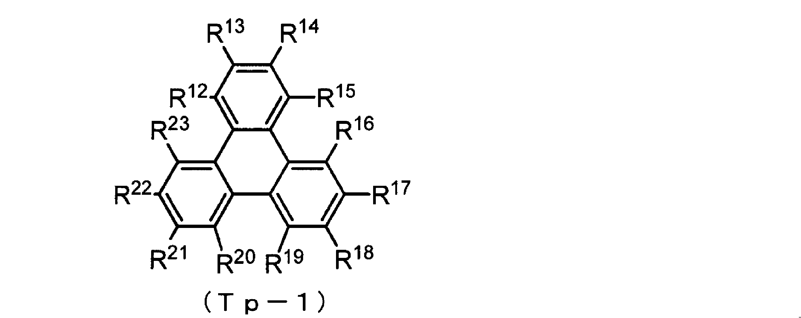
フェニル基、フルオレニル基、ナフチル基、若しくはトリフェニレニル基(これらは更にアルキル基、フェニル基、フルオレニル基、ナフチル基、若しくはトリフェニレニル基で置換されていてもよい)で置換されていてもよい、ベンゼン環であることが特に好ましい。
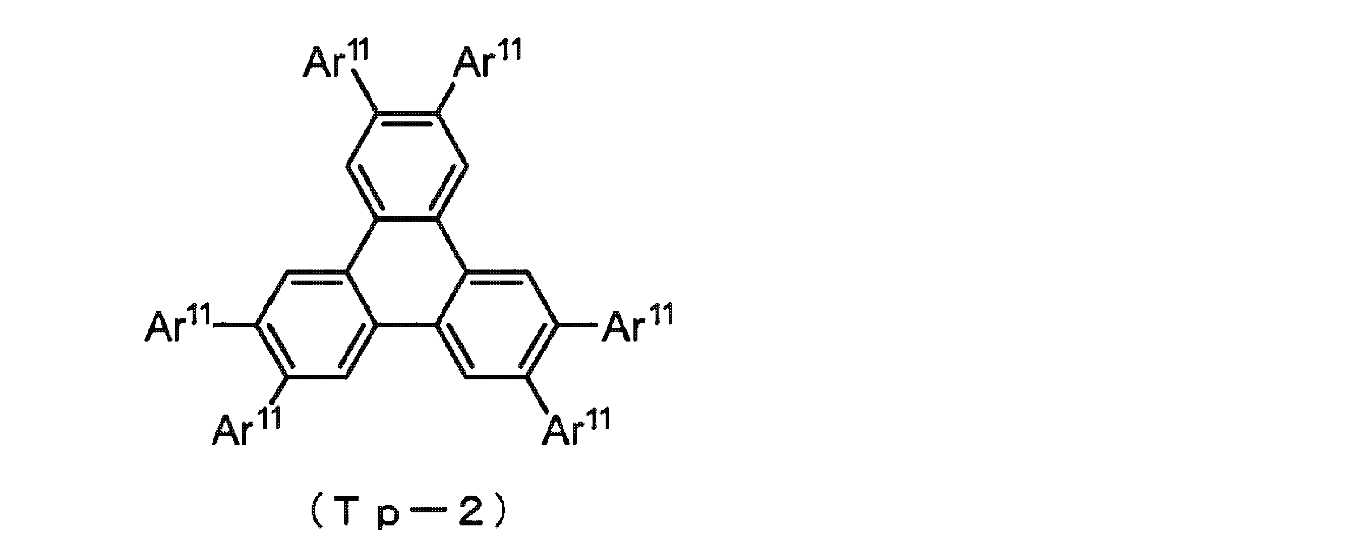
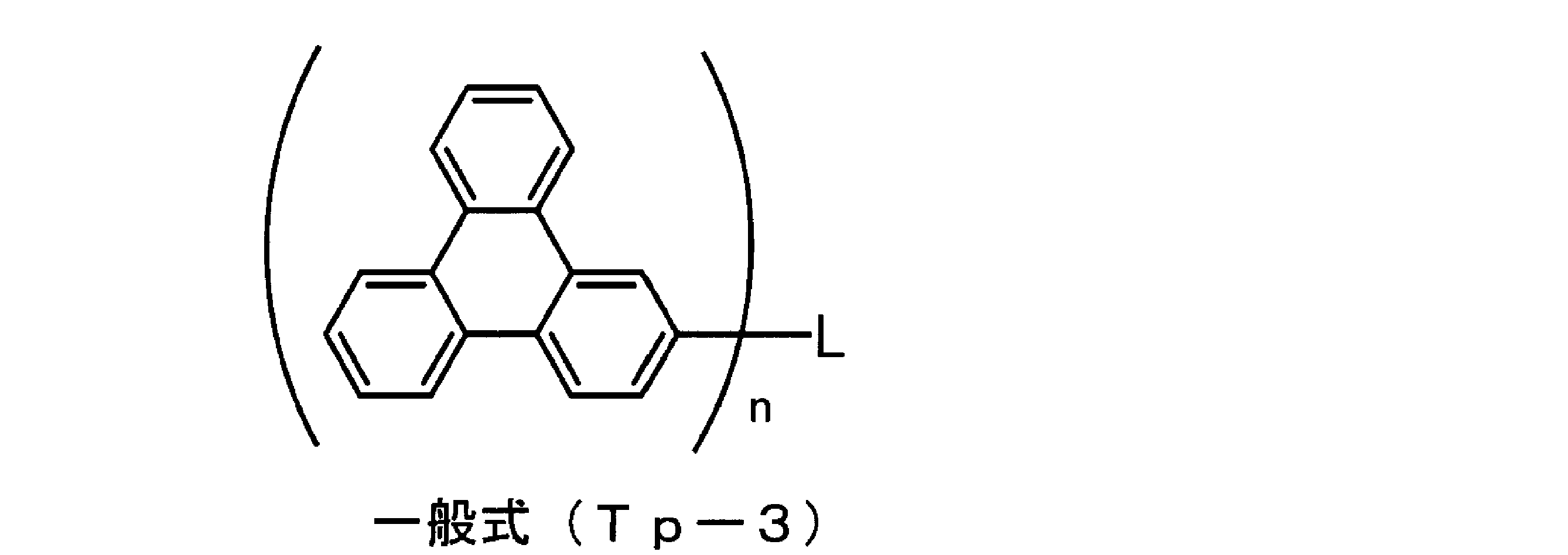
Lとして好ましくは、アルキル基又はベンゼン環で置換されていてもよいベンゼン環、フルオレン環、又はこれらを組み合わせて成るn価の連結基である。
以下にLの好ましい具体例を挙げるがこれらに限定されるものではない。なお具体例中*でトリフェニレン環と結合する。
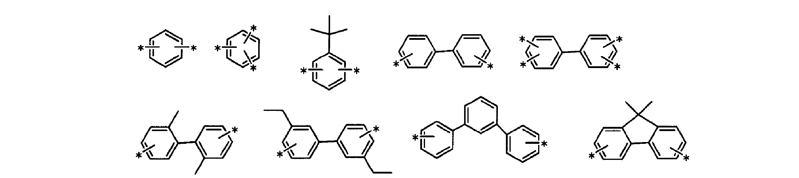
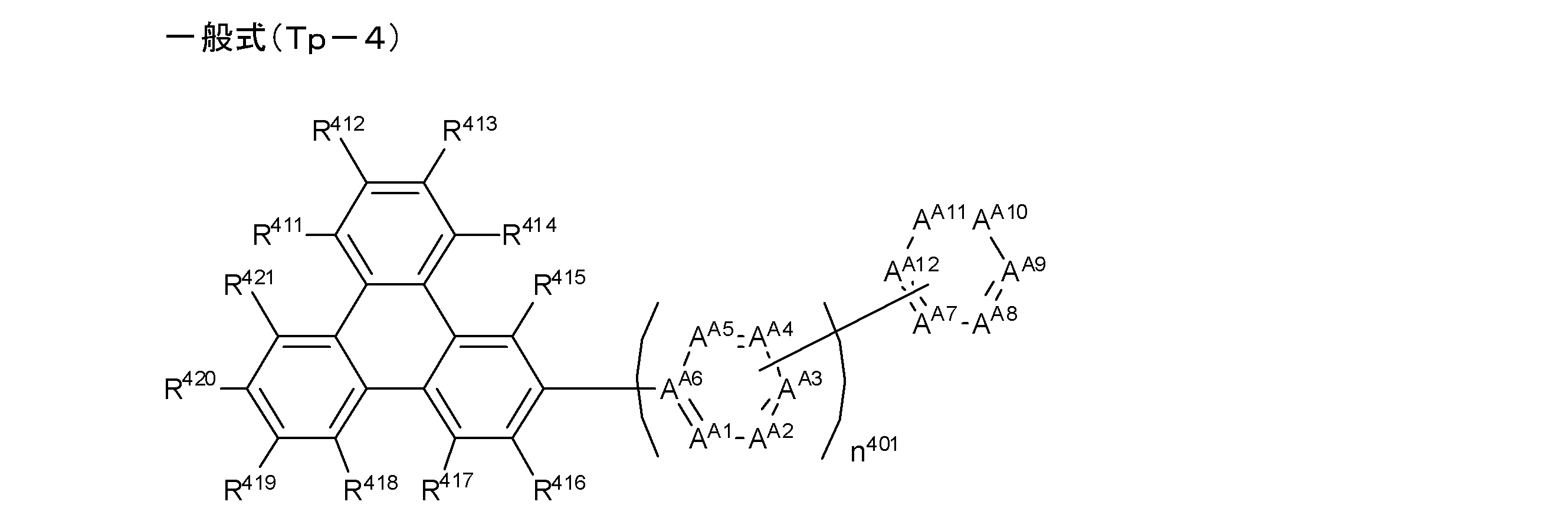
なお、本発明において、前記一般式(Tp-4)の説明における水素原子は同位体(重水素原子等)も含み、また更に置換基を構成する原子は、その同位体も含んでいることを表す。
前記一般式(Tp-4)において、R411~R421はそれぞれ独立に水素原子、アルキル基、フェニル基、フルオレニル基、ナフチル基、またはトリフェニレニル基(これらは更にアルキル基、フェニル基、フルオレニル基、ナフチル基、若しくはトリフェニレニル基で置換されていてもよい)を表す。
R411~R421として好ましくは、水素原子、炭素数1~4のアルキル基、フェニル基、フルオレニル基、ナフチル基、若しくはトリフェニレニル基(これらは更にアルキル基、フェニル基、フルオレニル基、ナフチル基、若しくはトリフェニレニル基で置換されていてもよい)であることが好ましく、水素原子、フェニル基(該フェニル基はアルキル基、フェニル基、フルオレニル基、ナフチル基、若しくはトリフェニレニル基で置換されていてもよい)であることが更に好ましく、水素原子であることが特に好ましい。
AA1~AA12として好ましくはCR400である。
前記一般式(Tp-4)中、R400が表す置換基としては、水素原子、炭素数1~4のアルキル基、フェニル基、フルオレニル基、ナフチル基、若しくはトリフェニレニル基(これらは更にアルキル基、フェニル基、フルオレニル基、ナフチル基、若しくはトリフェニレニル基で置換されていてもよい)を表す。複数存在するR400はそれぞれ異なっていてもよい。
R400として好ましくは、水素原子、炭素数1~4のアルキル基、フェニル基、フルオレニル基、ナフチル基、若しくはトリフェニレニル基(これらは更にアルキル基、フェニル基、フルオレニル基、ナフチル基、若しくはトリフェニレニル基で置換されていてもよい)であることが好ましく、水素原子、炭素数1~4のアルキル基、フェニル基(該フェニル基はアルキル基、フェニル基、フルオレニル基、ナフチル基、若しくはトリフェニレニル基で置換されていてもよい)であることが更に好ましく、水素原子、炭素数1~4のアルキル基、フェニル基(該フェニル基はアルキル基、フェニル基、フルオレニル基、ナフチル基、若しくはトリフェニレニル基で置換されていてもよい)であることが特に好ましい。
n401として好ましくは0~5の整数であり、1~5の整数であることがさらに好ましく、2~4であることが特に好ましい。
n401は1以上の整数であり、AA7~AA12で表される環と連結する位置がAA3である場合、発光効率の観点からAA4またはAA5で表される置換基はCR400であり、R400は炭素数1~4のアルキル基、フェニル基が好ましく、炭素数1~4のアルキル基が更に好ましく、メチル基であることが特に好ましい。
前記一般式(Tp-4)中、AA1~AA12によって構成される各6員環の芳香環のうち、窒素原子を含む環が1個以下であることが好ましく、0個であることがより好ましい。前記一般式(Tp-4)中、AA1~AA12によって構成される各6員環の芳香環の連結に制限はないが、メタ位またはパラ位で連結していることが好ましい。よりさらに、前記一般式(Tp-4)で表される化合物は、トリフェニレン環を構成する縮環の部分構造であるフェニル環を含め、パラ位で連続して連結している芳香環の個数が3個以下であることが好ましい。


合成後、カラムクロマトグラフィー、再結晶等による精製を行った後、昇華精製により精製することが好ましい。昇華精製により、有機不純物を分離できるだけでなく、無機塩や残留溶媒等を効果的に取り除くことができる。
前記(B)陰極と前記発光層との間に好ましく配置される有機層の材料に特に好ましく用いられる材料として、下記一般式(O-1)で表される化合物を用いることが、有機電界発光素子の効率や駆動電圧の観点から好ましい。以下に、一般式(O-1)について説明する。
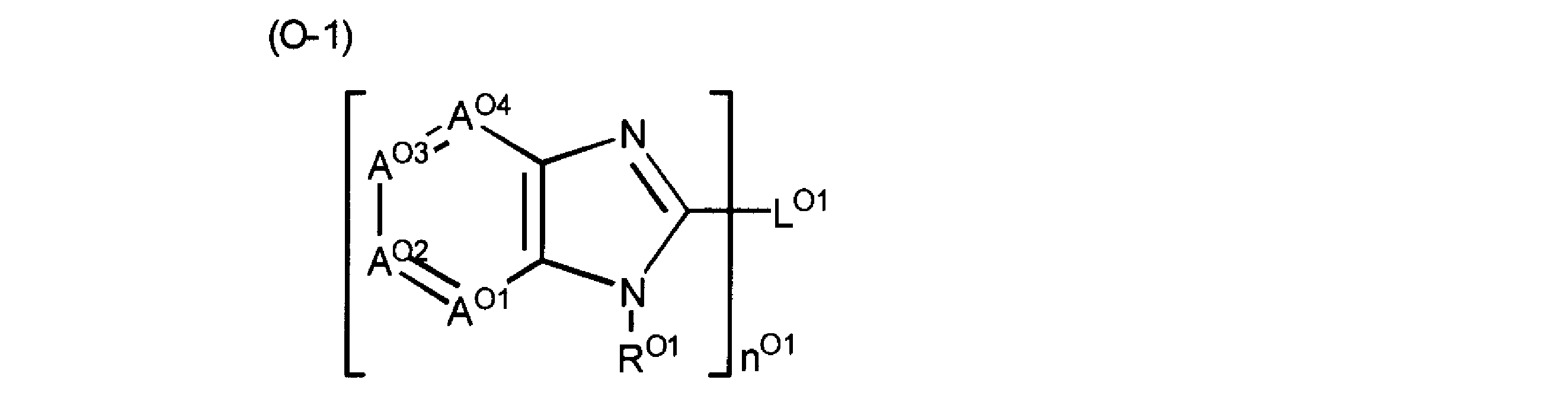
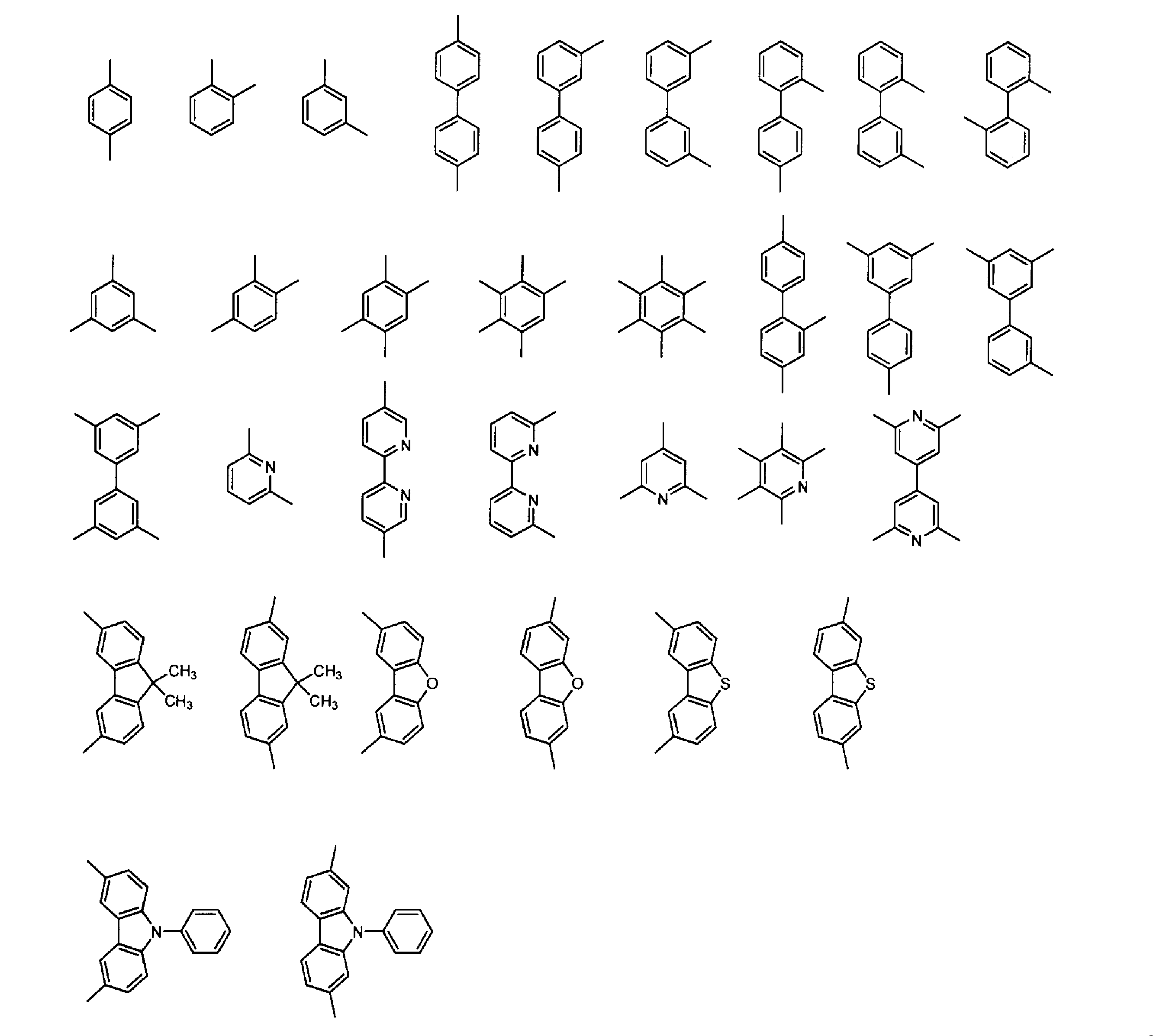
前記一般式(O-1)で表される化合物は、より好ましくは下記一般式(O-2)で表される化合物である。
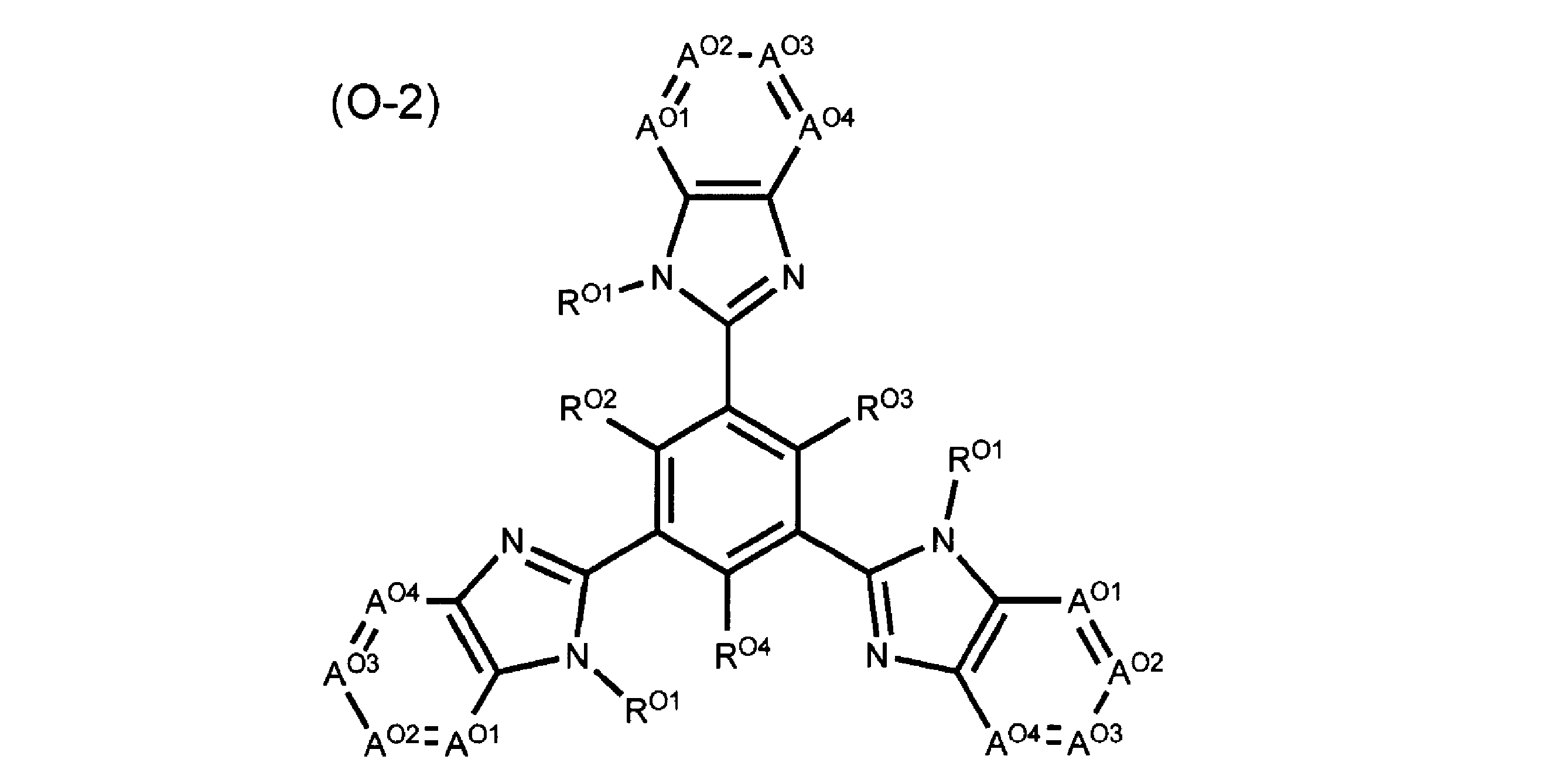
R02~R04はそれぞれ独立に、水素原子、アルキル基(好ましくは炭素数1~8)、アリール基(好ましくは炭素数6~30)、又はヘテロアリール基(好ましくは炭素数4~12)を表し、これらは前述の置換基群Aを有していてもよい。R02~R04として好ましくは水素原子、アルキル基、又はアリール基であり、より好ましくは水素原子、又はアリール基であり、最も好ましくは水素原子である。

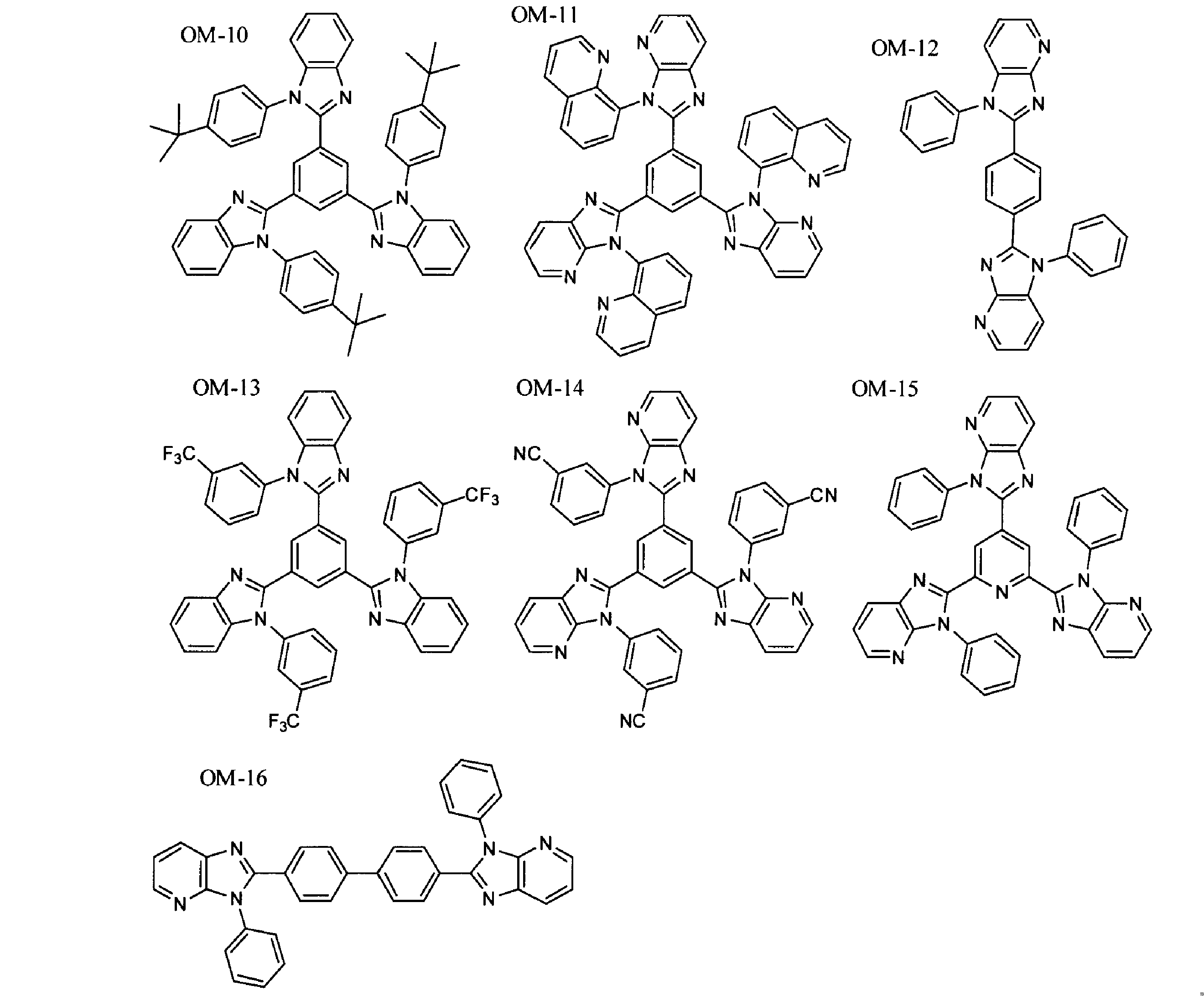
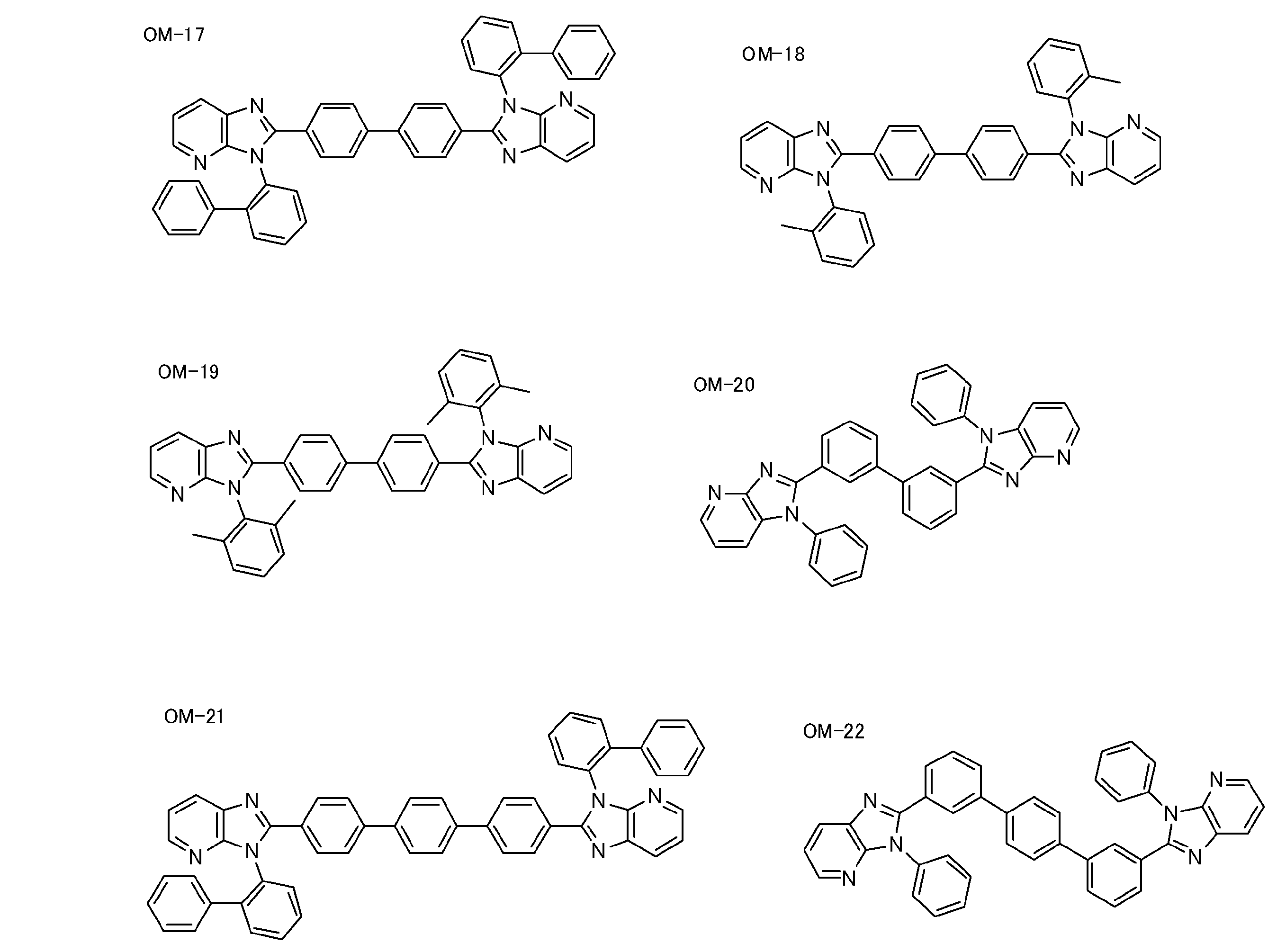
本発明において、有機電界発光素子全体は、保護層によって保護されていてもよい。
保護層については、特開2008-270736号公報の段落番号〔0169〕~〔0170〕に記載の事項を本発明に適用することができる。なお、保護層の材料は無機物であっても、有機物であってもよい。
本発明の有機電界発光素子は、封止容器を用いて素子全体を封止してもよい。
封止容器については、特開2008-270736号公報の段落番号〔0171〕に記載の事項を本発明に適用することができる。
本発明の有機電界発光素子は、陽極と陰極との間に直流(必要に応じて交流成分を含んでもよい)電圧(通常2ボルト~15ボルト)、又は直流電流を印加することにより、発光を得ることができる。
本発明の有機電界発光素子の駆動方法については、特開平2-148687号、同6-301355号、同5-29080号、同7-134558号、同8-234685号、同8-241047号の各公報、特許第2784615号、米国特許5828429号、同6023308号の各明細書等に記載の駆動方法を適用することができる。
本発明の有機電界発光素子は、その発光波長に制限はない。例えば、光の三原色のうち、赤色の発光に用いても、緑色の発光に用いても、青色の発光に用いてもよい。その中でも、本発明の有機電界発光素子は、発光ピーク波長が400~700nmであることが、前記一般式(1)で表される化合物の最低励起三重項(T1)エネルギーを考慮した発光効率の観点から好ましい。
具体的には、本発明の有機電界発光素子において、前記一般式(1)で表される化合物を発光層のホスト材料、電子輸送層または正孔ブロック層の電子輸送材料として用いる場合は、ゲスト材料の発光ピーク波長が400~700nmであることが好ましく、450~650nmであることがより好ましく、480~550nmであることが特に好ましい。
本発明の有機電界発光素子は、表示素子、ディスプレイ、バックライト、電子写真、照明光源、記録光源、露光光源、読み取り光源、標識、看板、インテリア、又は光通信等に好適に利用できる。特に、発光装置、照明装置、表示装置等の発光輝度が高い領域で駆動されるデバイスに好ましく用いられる。
本発明の発光装置は、本発明の有機電界発光素子を含むことを特徴とする。
次に、図2を参照して本発明の発光装置について説明する。
図2は、本発明の発光装置の一例を概略的に示した断面図である。図2の発光装置20は、透明基板(支持基板)2、有機電界発光素子10、封止容器16等により構成されている。
ここで、接着層14としては、エポキシ樹脂等の光硬化型接着剤や熱硬化型接着剤を用いることができ、例えば熱硬化性の接着シートを用いることもできる。
本発明の照明装置は、本発明の有機電界発光素子を含むことを特徴とする。
次に、図3を参照して本発明の照明装置について説明する。
図3は、本発明の照明装置の一例を概略的に示した断面図である。本発明の照明装置40は、図3に示すように、前述した有機EL素子10と、光散乱部材30とを備えている。より具体的には、照明装置40は、有機EL素子10の基板2と光散乱部材30とが接触するように構成されている。
光散乱部材30は、光を散乱できるものであれば特に制限されないが、図3においては、透明基板31に微粒子32が分散した部材とされている。透明基板31としては、例えば、ガラス基板を好適に挙げることができる。微粒子32としては、透明樹脂微粒子を好適に挙げることができる。ガラス基板及び透明樹脂微粒子としては、いずれも、公知のものを使用できる。このような照明装置40は、有機電界発光素子10からの発光が散乱部材30の光入射面30Aに入射されると、入射光を光散乱部材30により散乱させ、散乱光を光出射面30Bから照明光として出射するものである。
本発明の表示装置は、本発明の有機電界発光素子を含むことを特徴とする。
本発明の表示装置としては、例えば、テレビ、パーソナルコンピュータ、携帯電話、電子ペーパ等の表示装置とすることなどを挙げることができる。
(化合物No O-10-10の合成)

有機電界発光素子の作製に用いた材料は全て昇華精製を行った。比較例、及び実施例に用いた化合物を示す。

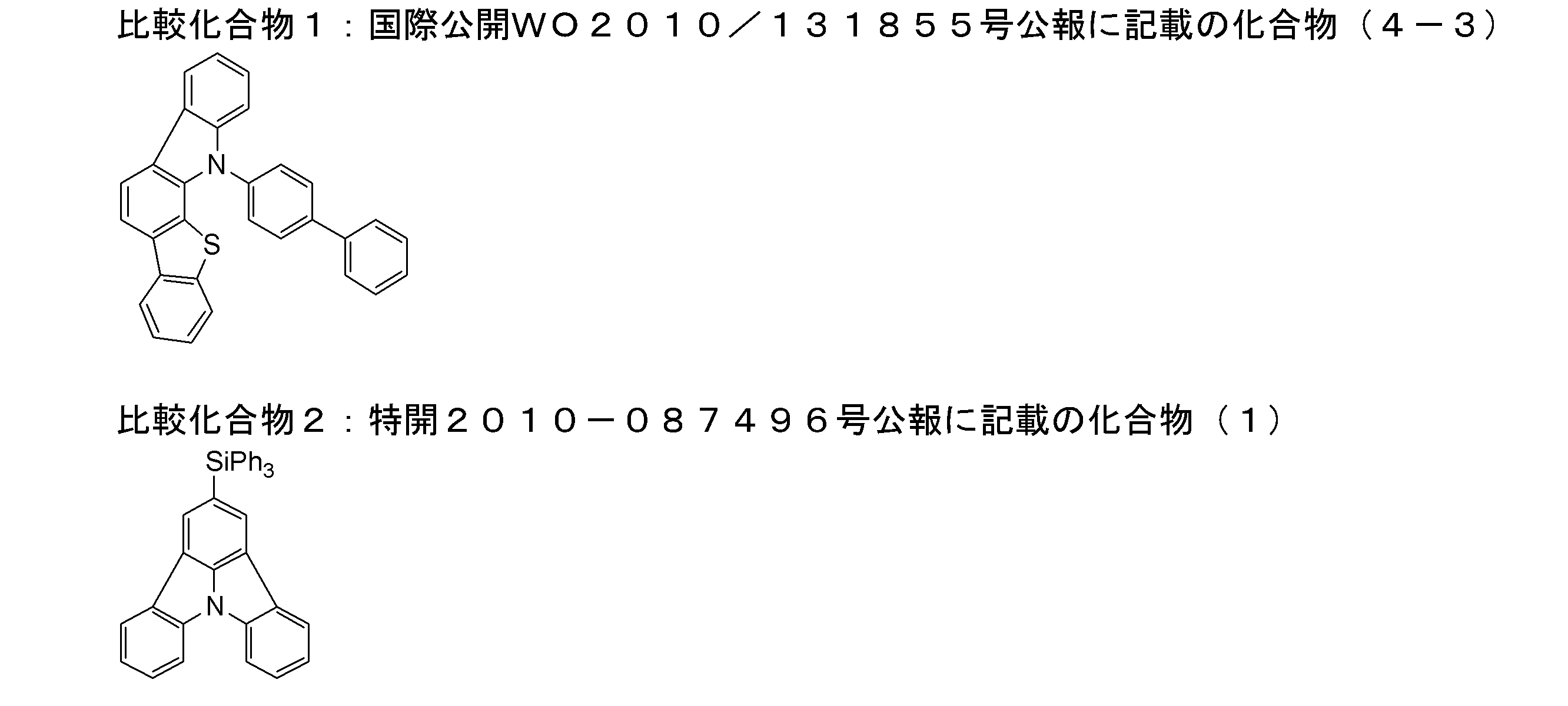
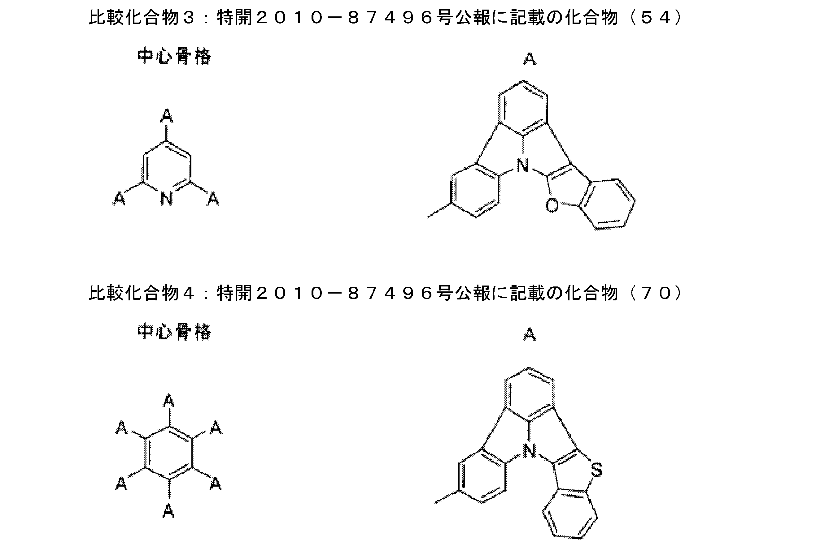
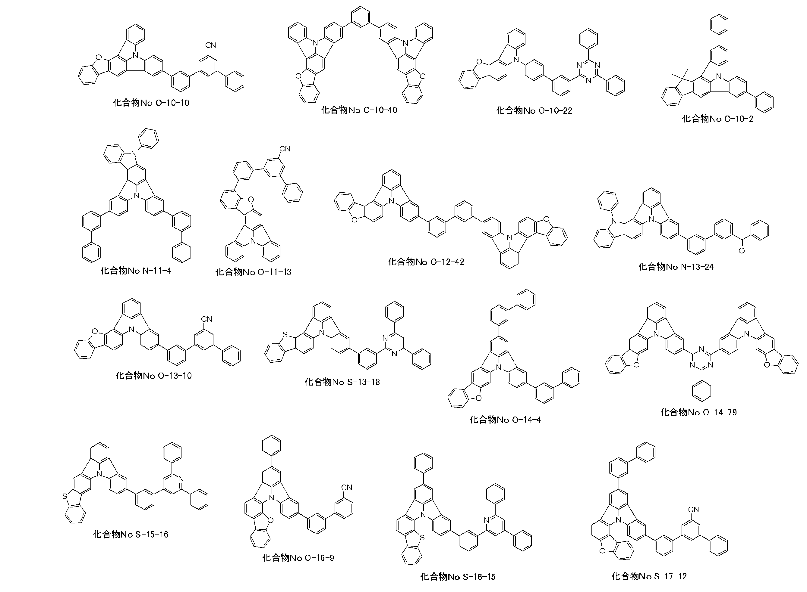
(陽極の作製)
厚み0.5mm、2.5cm角のITO膜を有するガラス基板(ジオマテック社製、表面抵抗10Ω/□)を洗浄容器に入れ、2-プロパノール中で超音波洗浄した後、30分間UV-オゾン処理を行った。
これを陽極(ITO膜、透明陽極)として用いた。
上記の陽極上に、真空蒸着法にて以下の化合物を用いて、第一層~第五層の有機層を順次蒸着した。あわせて、各層に用いた化合物の構造を示した。
第一層:LG101 :膜厚10nm
第二層:NPD :膜厚30nm
第三層:比較化合物1(ホスト材料)及び緑色燐光発光材料GD-1(ゲスト材料)(質量比85:15) :膜厚30nm
第四層:TpH-18 :膜厚10nm
第五層:Alq :膜厚40nm
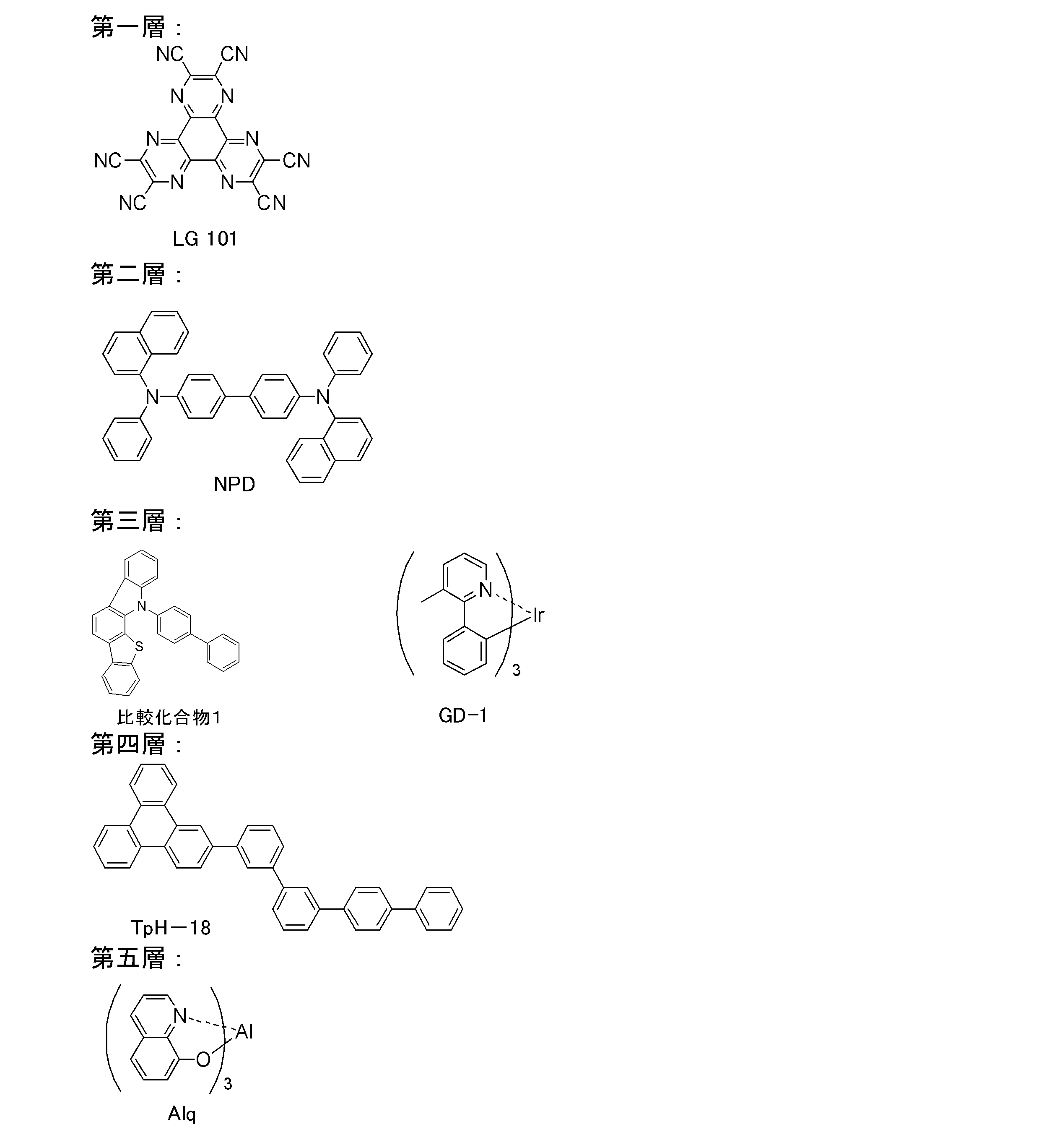
この上に、フッ化リチウム0.1nm及び金属アルミニウム200nmをこの順に蒸着し、陰極とした。
この陰極と陽極間に5層の有機層を有する積層体を、大気に触れさせることなく、窒素ガスで置換したグローブボックス内に入れ、ガラス製の封止缶及び紫外線硬化型の接着剤(XNR5516HV、長瀬チバ(株)製)を用いて封止し、比較例1の有機電界発光素子を得た。
(a) 耐久性
比較例1の有機電界発光素子を、室温で輝度が8000cd/m2になるように直流電圧を印加して発光させ続け、輝度が7200cd/m2になるまでに要した時間を測定した。この時間を、有機電界発光素子の耐久性の指標とした。
なお、後述の各実施例および比較例では、以下に記載する各表において、比較例1の有機電界発光素子を用いたときの耐久性を100とし、耐久性の相対値が100未満のものを×、100以上120未満のものを○、120以上のものを◎とした。
ここで、耐久性は数字が大きいほど好ましい。
比較例1の有機電界発光素子を輝度が1000cd/m2になるように、直流電圧を印加して発光させる。この時の印加電圧を駆動電圧評価の指標とした。
なお、後述の各実施例および比較例では、比較例1の有機電界発光素子の印加電圧を100とし、電圧の相対値が100以上のものを×、90以上100未満のものを○、90未満のものを◎とした。
ここで、駆動電圧は数字が小さいほど好ましい。
有機層の第3層の材料として、比較化合物1の代わりに本件の化合物または比較化合物2~4を用いた以外は比較例1と同様にして、実施例A1~A14及び比較例2の有機電界発光素子を得た。
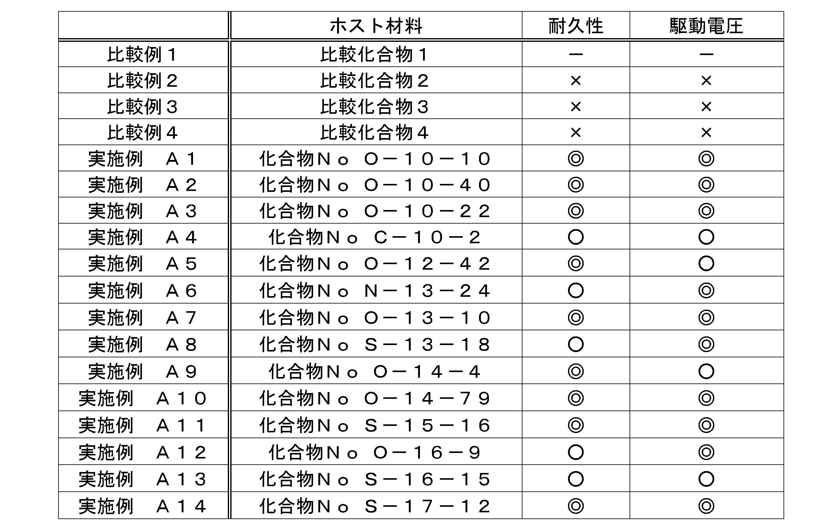
第二層に用いたNPDをHTL-1に、第三層に用いたGD-1をGD-2に、第四層に用いたTpH-18をOM-8に、第五層に用いたAlqをOM-8にかえた以外は比較例1と同様にして、比較例5の有機電界発光素子を作製した。比較例5における有機層の構成を下記に示す。
第一層:LG101 :膜厚10nm
第二層:HTL-1 :膜厚30nm
第三層:比較化合物1(ホスト材料)及び緑色燐光発光材料GD-2(ゲスト材料)(質量比85:15) :膜厚30nm
第四層:OM-8 :膜厚10nm
第五層:OM-8 :膜厚40nm
有機層の第3層の材料として、比較化合物1の代わりに本件の化合物または比較化合物2を用いた以外は比較例5と同様にして、実施例B1~B14及び比較例4の有機電界発光素子を得た。
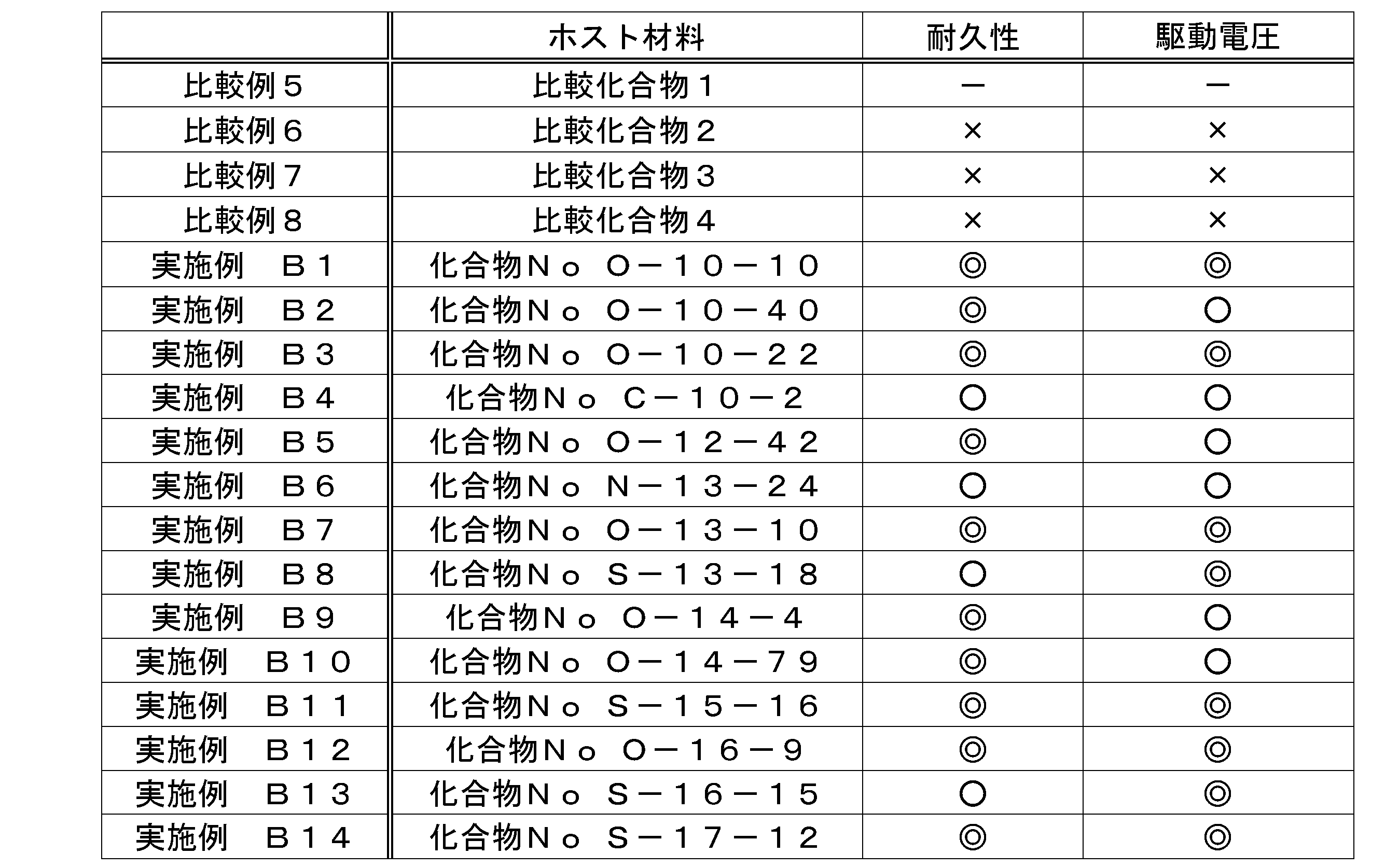
第一層に用いたLG101をGD-1に代え、第三層に用いたGD-1を赤色燐光発光材料RD-1に代え、第四層に用いたTpH-18をAlqにかえた以外は比較例1と同様にして、比較例9の有機電界発光素子を作製した。比較例9における有機層の構成を下記に示す。
第一層:GD-1 :膜厚10nm
第二層:NPD :膜厚30nm
第三層:比較化合物1(ホスト材料)及び赤色燐光発光材料RD-1(ゲスト材料)(質量比90:10) :膜厚30nm
第四層:Alq :膜厚10nm
第五層:Alq :膜厚40nm
有機層の第3層の材料として、比較化合物1の代わりに本件の化合物または比較化合物2を用いた以外は比較例9と同様にして、実施例C1~C10及び比較例10~12の有機電界発光素子を得た。

3・・・陽極
4・・・正孔注入層
5・・・正孔輸送層
6・・・発光層
7・・・正孔ブロック層
8・・・電子輸送層
9・・・陰極
10・・・有機電界発光素子(有機EL素子)
11・・・有機層
12・・・保護層
14・・・接着層
16・・・封止容器
20・・・発光装置
30・・・光散乱部材
30A・・・光入射面
30B・・・光出射面
31・・・透明基板
32・・・微粒子
40・・・照明装置
Claims (19)
- 基板と、
該基板上に配置され、陽極及び陰極からなる一対の電極と、
該電極間に配置され、発光層を含む少なくとも一層の有機層とを有し、
前記有機層の少なくとも一層に下記一般式(1)で表される化合物を含むことを特徴とする有機電界発光素子。
一般式(1)

- 前記一般式(1)において、R0どうしが互いに結合して環を形成する前記隣接する2つのCR0の一方のR0が、6員環のアリール基またはヘテロアリール基を表すことを特徴とする請求項1に記載の有機電界発光素子。
- 前記一般式(1)で表される化合物が、下記一般式(2)~(9)のいずれかで表される化合物であることを特徴とする請求項1または2に記載の有機電界発光素子。
 (一般式(2)~(9)中、YA1~YH1はそれぞれ独立にCR1R2、NR3、O、SまたはSeを表し、R1~R3はそれぞれ独立に置換基を表す。XA1~XA15、XB1~XB15、XC1~XC15、XD1~XD15、XE1~XE15、XF1~XF15、XG1~XG15およびXH1~XH15はそれぞれ独立にCR4またはNを表し、CR4はそれぞれ独立に水素原子または置換基を表す。)
- 前記一般式(1)で表される化合物が、下記一般式(10)~(17)のいずれかで表される化合物であることを特徴とする請求項1または2に記載の有機電界発光素子。

- 前記一般式(1)で表される化合物のLUMOの値が、電子密度汎関数法(B3LYP/6-31G(d)レベル)で求めたとき、1.25よりも大きい化合物であることを特徴とする請求項1~4のいずれか一項に記載の有機電界発光素子。
- 前記一般式(1)で表される化合物が、ピリジン環、ピリミジン環、トリアジン環、シアノ基およびカルボニル基のうち少なくとも1つを含む置換基を有する化合物であることを特徴とする請求項1~5のいずれか一項に記載の有機電界発光素子。
- 前記発光層に燐光発光材料を少なくとも一種含むことを特徴とする請求項1~6のいずれか一項に記載の有機電界発光素子。
- 前記燐光発光材料が、下記一般式(E-1)で表されるイリジウム錯体であることを特徴とする請求項1~6のいずれか一項に記載の有機電界発光素子。

A1はZ1と窒素原子と共に5又は6員のヘテロ環を形成する原子群を表す。
B1はZ2と炭素原子と共に5又は6員環を形成する原子群を表す。
(X-Y)はモノアニオン性の二座配位子を表す。
nE1は1~3の整数を表す。) - 前記一般式(E-1)で表されるイリジウム錯体が下記一般式(E-2)で表されることを特徴とする請求項8に記載の有機電界発光素子。

REは水素原子又は置換基を表す。
(X-Y)はモノアニオン性の二座配位子を表す。
nE2は1~3の整数を表す。) - 前記発光層が前記一般式(1)で表される化合物を含有することを特徴とする請求項1~9のいずれか一項に記載の有機電界発光素子。
- 請求項1~10のいずれか一項に記載の有機電界発光素子を用いた発光装置。
- 請求項1~10のいずれか一項に記載の有機電界発光素子を用いた表示装置。
- 請求項1~10のいずれか一項に記載の有機電界発光素子を用いた照明装置。
- 下記一般式(1)で表される化合物。
一般式(1)

- 下記一般式(2)~(9)のいずれかで表されることを特徴とする請求項14に記載の化合物。
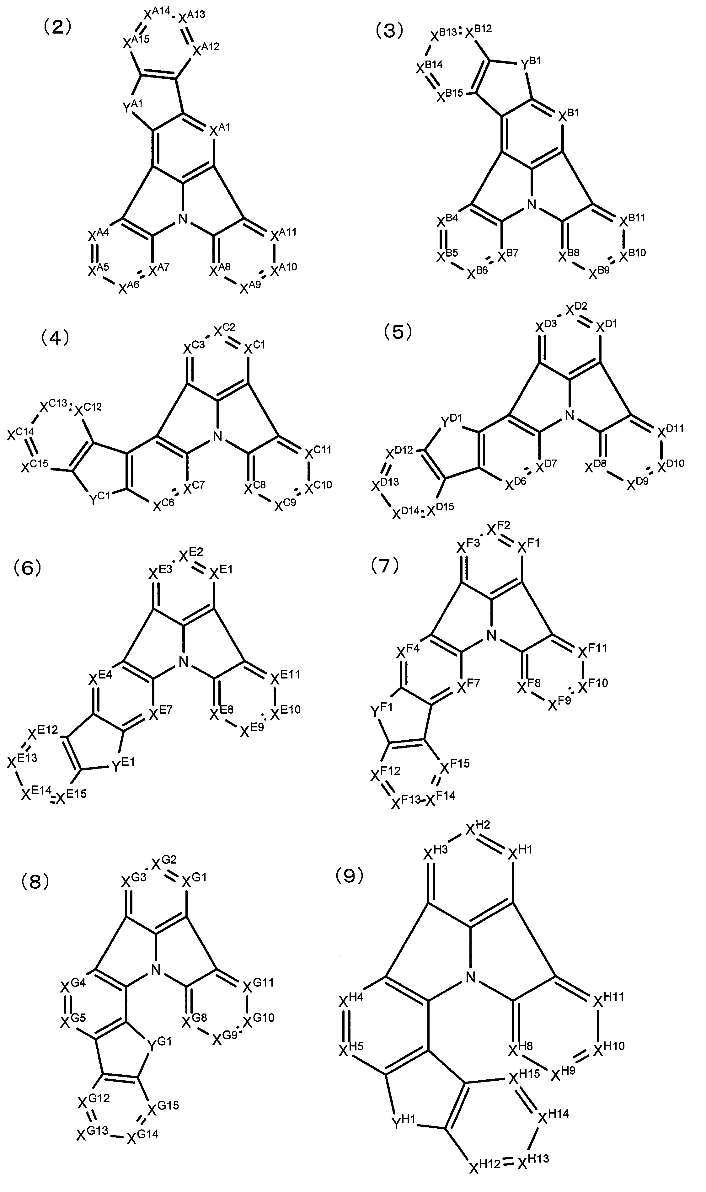
- 下記一般式(10)~(17)のいずれかで表されることを特徴とする請求項14または15に記載の化合物。

- 下記一般式(1)で表される有機電界発光素子用材料。
一般式(1)

- 下記一般式(2)~(9)のいずれかで表されることを特徴とする請求項17に記載の有機電界発光素子用材料。
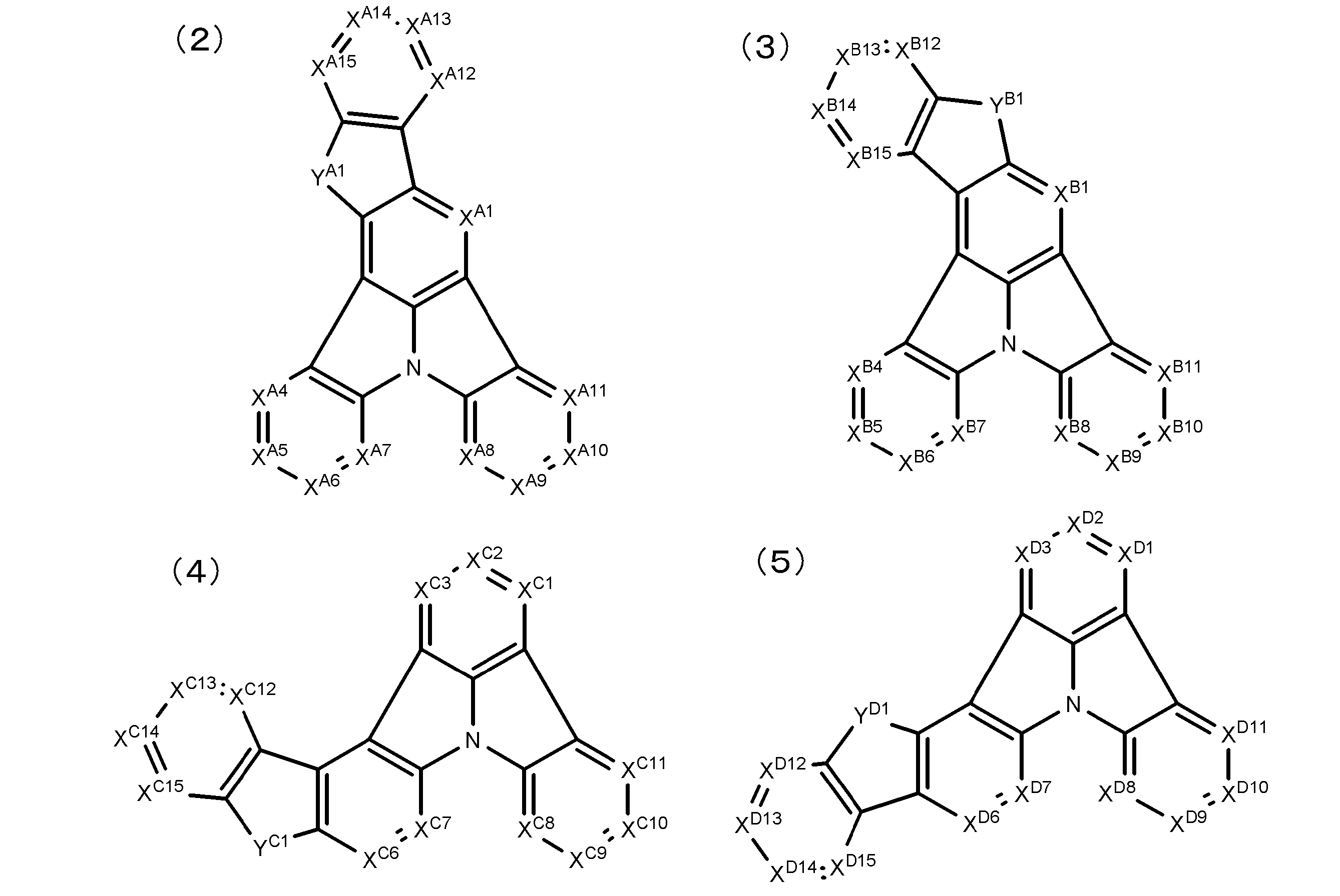 (一般式(2)~(9)中、YA1~YH1はそれぞれ独立にCR1R2、NR3、O、SまたはSeを表し、R1~R3はそれぞれ独立に置換基を表す。XA1~XA15、XB1~XB15、XC1~XC15、XD1~XD15、XE1~XE15、XF1~XF15、XG1~XG15およびXH1~XH15はそれぞれ独立にCR4またはNを表し、CR4はそれぞれ独立に水素原子または置換基を表す。)
- 下記一般式(10)~(17)のいずれかで表されることを特徴とする請求項17または18に記載の有機電界発光素子用材料。

Priority Applications (13)
| Application Number | Priority Date | Filing Date | Title |
|---|---|---|---|
| KR1020217039851A KR102428456B1 (ko) | 2011-11-22 | 2012-11-21 | 유기 전계 발광 소자, 유기 전계 발광 소자용 재료, 그리고 그 소자를 사용한 발광 장치, 표시 장치, 조명 장치 및 그 소자에 사용되는 화합물 |
| KR1020227026379A KR102529112B1 (ko) | 2011-11-22 | 2012-11-21 | 유기 전계 발광 소자, 유기 전계 발광 소자용 재료, 그리고 그 소자를 사용한 발광 장치, 표시 장치, 조명 장치 및 그 소자에 사용되는 화합물 |
| DE112012004870.9T DE112012004870B4 (de) | 2011-11-22 | 2012-11-21 | Organisches Elektrolumineszenzelement und in dem Element verwendete Verbindung |
| KR1020207032189A KR102337199B1 (ko) | 2011-11-22 | 2012-11-21 | 유기 전계 발광 소자, 유기 전계 발광 소자용 재료, 그리고 그 소자를 사용한 발광 장치, 표시 장치, 조명 장치 및 그 소자에 사용되는 화합물 |
| KR1020247035769A KR102846158B1 (ko) | 2011-11-22 | 2012-11-21 | 유기 전계 발광 소자, 유기 전계 발광 소자용 재료, 그리고 그 소자를 사용한 발광 장치, 표시 장치, 조명 장치 및 그 소자에 사용되는 화합물 |
| KR1020237042461A KR102723976B1 (ko) | 2011-11-22 | 2012-11-21 | 유기 전계 발광 소자, 유기 전계 발광 소자용 재료, 그리고 그 소자를 사용한 발광 장치, 표시 장치, 조명 장치 및 그 소자에 사용되는 화합물 |
| KR1020167032342A KR102052575B1 (ko) | 2011-11-22 | 2012-11-21 | 유기 전계 발광 소자, 유기 전계 발광 소자용 재료, 그리고 그 소자를 사용한 발광 장치, 표시 장치, 조명 장치 및 그 소자에 사용되는 화합물 |
| KR1020257026708A KR20250127173A (ko) | 2011-11-22 | 2012-11-21 | 유기 전계 발광 소자, 유기 전계 발광 소자용 재료, 그리고 그 소자를 사용한 발광 장치, 표시 장치, 조명 장치 및 그 소자에 사용되는 화합물 |
| KR1020147016395A KR20140101807A (ko) | 2011-11-22 | 2012-11-21 | 유기 전계 발광 소자, 유기 전계 발광 소자용 재료, 그리고 그 소자를 사용한 발광 장치, 표시 장치, 조명 장치 및 그 소자에 사용되는 화합물 |
| KR1020237014786A KR102613003B1 (ko) | 2011-11-22 | 2012-11-21 | 유기 전계 발광 소자, 유기 전계 발광 소자용 재료, 그리고 그 소자를 사용한 발광 장치, 표시 장치, 조명 장치 및 그 소자에 사용되는 화합물 |
| US14/351,151 US11171293B2 (en) | 2011-11-22 | 2012-11-21 | Organic electroluminescent element, material for organic electroluminescent element, light emitting device, display device and lighting device each using said element, and compound used for said element |
| KR1020197035479A KR102178240B1 (ko) | 2011-11-22 | 2012-11-21 | 유기 전계 발광 소자, 유기 전계 발광 소자용 재료, 그리고 그 소자를 사용한 발광 장치, 표시 장치, 조명 장치 및 그 소자에 사용되는 화합물 |
| US17/173,532 US12552803B2 (en) | 2011-11-22 | 2021-02-11 | Organic electroluminescent element, material for organic electroluminescent element, light emitting device, display device and lighting device each using said element, and compound used for said element |
Applications Claiming Priority (2)
| Application Number | Priority Date | Filing Date | Title |
|---|---|---|---|
| JP2011-254821 | 2011-11-22 | ||
| JP2011254821 | 2011-11-22 |
Related Child Applications (2)
| Application Number | Title | Priority Date | Filing Date |
|---|---|---|---|
| US14/351,151 A-371-Of-International US11171293B2 (en) | 2011-11-22 | 2012-11-21 | Organic electroluminescent element, material for organic electroluminescent element, light emitting device, display device and lighting device each using said element, and compound used for said element |
| US17/173,532 Continuation US12552803B2 (en) | 2011-11-22 | 2021-02-11 | Organic electroluminescent element, material for organic electroluminescent element, light emitting device, display device and lighting device each using said element, and compound used for said element |
Publications (1)
| Publication Number | Publication Date |
|---|---|
| WO2013077344A1 true WO2013077344A1 (ja) | 2013-05-30 |
Family
ID=48469786
Family Applications (1)
| Application Number | Title | Priority Date | Filing Date |
|---|---|---|---|
| PCT/JP2012/080131 Ceased WO2013077344A1 (ja) | 2011-11-22 | 2012-11-21 | 有機電界発光素子、有機電界発光素子用材料、並びに、該素子を用いた発光装置、表示装置、照明装置及び該素子に用いられる化合物 |
Country Status (6)
| Country | Link |
|---|---|
| US (2) | US11171293B2 (ja) |
| JP (5) | JPWO2013077344A1 (ja) |
| KR (10) | KR102052575B1 (ja) |
| DE (1) | DE112012004870B4 (ja) |
| TW (2) | TWI606051B (ja) |
| WO (1) | WO2013077344A1 (ja) |
Cited By (24)
| Publication number | Priority date | Publication date | Assignee | Title |
|---|---|---|---|---|
| JP2014232858A (ja) * | 2012-07-31 | 2014-12-11 | 株式会社半導体エネルギー研究所 | 発光素子、複素環化合物、ディスプレイモジュール、照明モジュール、発光装置、表示装置、照明装置及び電子機器 |
| KR20150135125A (ko) | 2014-05-23 | 2015-12-02 | 롬엔드하스전자재료코리아유한회사 | 유기 전계 발광 화합물 및 이를 포함하는 유기 전계 발광 소자 |
| WO2016013533A1 (ja) * | 2014-07-23 | 2016-01-28 | 日産化学工業株式会社 | 電荷輸送性材料 |
| JP2017521525A (ja) * | 2014-07-09 | 2017-08-03 | ローム・アンド・ハース・エレクトロニック・マテリアルズ・コリア・リミテッド | 有機電界発光化合物及びそれを含む有機電界発光デバイス |
| WO2017175690A1 (ja) | 2016-04-08 | 2017-10-12 | 出光興産株式会社 | 新規な化合物、有機エレクトロルミネッセンス素子及び電子機器 |
| JP2017199925A (ja) * | 2011-11-22 | 2017-11-02 | ユー・ディー・シー アイルランド リミテッド | 有機電界発光素子、有機電界発光素子用材料、並びに、該素子を用いた発光装置、表示装置、照明装置及び該素子に用いられる化合物 |
| CN107428769A (zh) * | 2015-08-27 | 2017-12-01 | 株式会社Lg化学 | 杂环化合物及包含其的有机发光元件 |
| JP2017538657A (ja) * | 2015-06-03 | 2017-12-28 | エルジー・ケム・リミテッド | 含窒素縮合環化合物およびそれを用いた有機発光素子 |
| US9954187B2 (en) | 2016-04-08 | 2018-04-24 | Idemitsu Kosan Co., Ltd. | Compound, organic electroluminescence device and electronic device |
| WO2018151065A1 (ja) | 2017-02-14 | 2018-08-23 | 出光興産株式会社 | 有機エレクトロルミネッセンス素子及び電子機器 |
| JP2018532688A (ja) * | 2016-07-20 | 2018-11-08 | エルジー・ケム・リミテッド | 新規なヘテロ環式化合物およびこれを利用した有機発光素子 |
| JP2019506399A (ja) * | 2016-02-11 | 2019-03-07 | エルジー・ケム・リミテッド | ヘテロ環化合物およびこれを含む有機電界発光素子 |
| US10249832B1 (en) | 2017-12-06 | 2019-04-02 | Idemitsu Kosan Co., Ltd. | Organic electroluminescence device and novel compound |
| WO2019070082A1 (ja) | 2017-10-06 | 2019-04-11 | 出光興産株式会社 | 化合物、有機エレクトロルミネッセンス素子用材料、有機エレクトロルミネッセンス素子、及び電子機器 |
| WO2019111971A1 (ja) | 2017-12-06 | 2019-06-13 | 出光興産株式会社 | 有機エレクトロルミネッセンス素子及び新規化合物 |
| KR20190132645A (ko) | 2017-04-03 | 2019-11-28 | 이데미쓰 고산 가부시키가이샤 | 유기 전기발광 소자 및 전자 기기 |
| KR20190132644A (ko) | 2017-04-03 | 2019-11-28 | 이데미쓰 고산 가부시키가이샤 | 유기 전기발광 소자 및 전자 기기 |
| KR20190132646A (ko) | 2017-04-03 | 2019-11-28 | 이데미쓰 고산 가부시키가이샤 | 유기 전기발광 소자 및 전자 기기 |
| WO2019240251A1 (ja) * | 2018-06-15 | 2019-12-19 | 出光興産株式会社 | 有機エレクトロルミネッセンス素子及びそれを用いた電子機器 |
| US10593889B1 (en) | 2018-09-26 | 2020-03-17 | Idemitsu Kosan Co., Ltd. | Compound and organic electroluminescence device |
| WO2020115933A1 (ja) * | 2018-12-05 | 2020-06-11 | 出光興産株式会社 | 有機エレクトロルミネッセンス素子及びそれを用いた電子機器 |
| US20210355085A1 (en) * | 2020-02-27 | 2021-11-18 | Idemitsu Kosan Co.,Ltd. | Compound, and organic electroluminescence device and electronic apparatus using the same |
| US11795185B2 (en) | 2017-12-13 | 2023-10-24 | Lg Display Co., Ltd. | Compound for electron-transport material and organic light emitting diode including the same |
| US12232419B2 (en) | 2020-02-27 | 2025-02-18 | Idemitsu Kosan Co., Ltd. | Compound, and organic electroluminescence device and electronic apparatus using the same |
Families Citing this family (19)
| Publication number | Priority date | Publication date | Assignee | Title |
|---|---|---|---|---|
| KR102420202B1 (ko) * | 2014-06-27 | 2022-07-14 | 롬엔드하스전자재료코리아유한회사 | 신규한 유기 전계 발광 화합물 및 이를 포함하는 유기 전계 발광 소자 |
| KR102025360B1 (ko) * | 2016-06-17 | 2019-09-25 | 삼성에스디아이 주식회사 | 유기 광전자 소자용 화합물, 유기 광전자 소자 및 표시 장치 |
| KR102574912B1 (ko) * | 2016-08-17 | 2023-09-07 | 덕산네오룩스 주식회사 | 유기전기 소자용 화합물, 이를 이용한 유기전기소자 및 그 전자 장치 |
| KR101877961B1 (ko) * | 2016-10-11 | 2018-07-12 | 주식회사 엘지화학 | 신규한 화합물 및 이를 포함하는 유기발광 소자 |
| KR102597556B1 (ko) * | 2016-10-14 | 2023-11-03 | 덕산네오룩스 주식회사 | 유기전기 소자용 화합물, 이를 이용한 유기전기소자 및 그 전자 장치 |
| KR102597559B1 (ko) * | 2016-10-14 | 2023-11-03 | 덕산네오룩스 주식회사 | 유기전기 소자용 화합물, 이를 이용한 유기전기소자 및 그 전자 장치 |
| KR102427493B1 (ko) | 2017-11-14 | 2022-08-01 | 덕산네오룩스 주식회사 | 유기전기소자용 화합물을 이용한 유기전기소자 및 그 전자 장치 |
| JP6924353B2 (ja) * | 2018-03-29 | 2021-08-25 | サミー株式会社 | 遊技機 |
| JP6924351B2 (ja) * | 2018-03-29 | 2021-08-25 | サミー株式会社 | 遊技機 |
| CN110845499B (zh) * | 2018-12-10 | 2023-08-22 | 广州华睿光电材料有限公司 | 含氮多环化合物、高聚物、混合物、组合物及有机电子器件 |
| US11325932B2 (en) * | 2019-02-08 | 2022-05-10 | Universal Display Corporation | Organic electroluminescent materials and devices |
| KR20210024923A (ko) | 2019-08-26 | 2021-03-08 | 솔브레인 주식회사 | 화합물 및 이를 포함하는 유기 발광 소자 |
| KR102465752B1 (ko) * | 2019-09-05 | 2022-11-09 | 주식회사 엘지화학 | 신규한 화합물 및 이를 이용한 유기 발광 소자 |
| EP4263544A1 (de) | 2020-12-18 | 2023-10-25 | Merck Patent GmbH | Indolo[3.2.1-jk]carbazole-6-carbonitril-derivate als blau fluoreszierende emitter zur verwendung in oleds |
| KR20230122093A (ko) * | 2020-12-18 | 2023-08-22 | 메르크 파텐트 게엠베하 | 유기 전계 발광 디바이스용 질소 함유 화합물 |
| JP2022106470A (ja) * | 2021-01-07 | 2022-07-20 | エスケーマテリアルズジェイエヌシー株式会社 | 有機電界発光素子および多環芳香族化合物 |
| CN116143789B (zh) * | 2021-11-18 | 2026-02-06 | 奥来德(上海)光电材料科技有限公司 | 一种蓝色荧光掺杂化合物、其制备方法及其应用 |
| CN114805390B (zh) * | 2022-05-11 | 2024-01-05 | 武汉天马微电子有限公司 | 一种有机化合物及其电致发光的应用 |
| WO2025185754A1 (zh) * | 2024-03-08 | 2025-09-12 | 浙江光昊光电科技有限公司 | 一种有机混合物,一种有机化合物及其在有机电子器件中的应用 |
Citations (6)
| Publication number | Priority date | Publication date | Assignee | Title |
|---|---|---|---|---|
| WO2011060867A1 (de) * | 2009-11-18 | 2011-05-26 | Merck Patent Gmbh | Stickstoffhaltige kondensierte heterozyklen für oleds |
| WO2011088877A1 (de) * | 2010-01-25 | 2011-07-28 | Merck Patent Gmbh | Verbindungen für elektronische vorrichtungen |
| WO2011128017A1 (de) * | 2010-04-14 | 2011-10-20 | Merck Patent Gmbh | Überbrückte triarylamine und -phosphine als materialien für elektronische vorrichtungen |
| JP2012049523A (ja) * | 2010-07-30 | 2012-03-08 | Fujifilm Corp | 有機電界発光素子、及びジベンゾチオフェン構造又はジベンゾフラン構造を有する有機電界発光素子用材料 |
| JP2012072099A (ja) * | 2010-09-29 | 2012-04-12 | Canon Inc | インドロ[3,2,1−jk]カルバゾール化合物及びこれを有する有機発光素子 |
| JP2012191031A (ja) * | 2011-03-11 | 2012-10-04 | Konica Minolta Holdings Inc | 有機エレクトロルミネッセンス素子、表示装置及び照明装置 |
Family Cites Families (12)
| Publication number | Priority date | Publication date | Assignee | Title |
|---|---|---|---|---|
| US20020121638A1 (en) | 2000-06-30 | 2002-09-05 | Vladimir Grushin | Electroluminescent iridium compounds with fluorinated phenylpyridines, phenylpyrimidines, and phenylquinolines and devices made with such compounds |
| EP2566302B1 (en) | 2000-08-11 | 2015-12-16 | The Trustees of Princeton University | Organometallic compounds and emission-shifting organic electrophosphorence |
| DE10345572A1 (de) | 2003-09-29 | 2005-05-19 | Covion Organic Semiconductors Gmbh | Metallkomplexe |
| WO2010131855A2 (ko) | 2009-05-13 | 2010-11-18 | 덕산하이메탈(주) | 오원자 헤테로고리를 포함하는 화합물 및 이를 이용한 유기전기소자, 그 단말 |
| WO2009136595A1 (ja) | 2008-05-08 | 2009-11-12 | 新日鐵化学株式会社 | 有機電界発光素子用化合物及び有機電界発光素子 |
| JP5483962B2 (ja) * | 2008-09-04 | 2014-05-07 | ユー・ディー・シー アイルランド リミテッド | 有機電界発光素子 |
| JP5457907B2 (ja) | 2009-08-31 | 2014-04-02 | ユー・ディー・シー アイルランド リミテッド | 有機電界発光素子 |
| DE102009048791A1 (de) | 2009-10-08 | 2011-04-14 | Merck Patent Gmbh | Materialien für organische Elektrolumineszenzvorrichtungen |
| DE102010010481A1 (de) | 2010-03-06 | 2011-09-08 | Merck Patent Gmbh | Organische Elektrolumineszenzvorrichtung |
| JP4781474B1 (ja) | 2010-03-31 | 2011-09-28 | キヤノン株式会社 | 有機発光素子 |
| TWI606051B (zh) * | 2011-11-22 | 2017-11-21 | Udc愛爾蘭有限公司 | 有機電場發光元件、有機電場發光元件用材料以及使用該元件之發光裝置、顯示裝置、照明裝置及用於該元件之化合物 |
| JP2017128415A (ja) | 2016-01-20 | 2017-07-27 | 日本電気株式会社 | 片面凹部付き柱体部品整列装置および片面凹部付き柱体部品整列方法 |
-
2012
- 2012-11-09 TW TW101141810A patent/TWI606051B/zh active
- 2012-11-09 TW TW106131260A patent/TWI642672B/zh active
- 2012-11-21 KR KR1020167032342A patent/KR102052575B1/ko active Active
- 2012-11-21 KR KR1020227026379A patent/KR102529112B1/ko active Active
- 2012-11-21 US US14/351,151 patent/US11171293B2/en active Active
- 2012-11-21 KR KR1020257026708A patent/KR20250127173A/ko active Pending
- 2012-11-21 KR KR1020237014786A patent/KR102613003B1/ko active Active
- 2012-11-21 KR KR1020207032189A patent/KR102337199B1/ko active Active
- 2012-11-21 KR KR1020237042461A patent/KR102723976B1/ko active Active
- 2012-11-21 KR KR1020247035769A patent/KR102846158B1/ko active Active
- 2012-11-21 KR KR1020147016395A patent/KR20140101807A/ko not_active Ceased
- 2012-11-21 WO PCT/JP2012/080131 patent/WO2013077344A1/ja not_active Ceased
- 2012-11-21 DE DE112012004870.9T patent/DE112012004870B4/de active Active
- 2012-11-21 KR KR1020217039851A patent/KR102428456B1/ko active Active
- 2012-11-21 KR KR1020197035479A patent/KR102178240B1/ko active Active
- 2012-11-21 JP JP2013545942A patent/JPWO2013077344A1/ja not_active Withdrawn
-
2017
- 2017-06-30 JP JP2017128415A patent/JP6582018B2/ja active Active
-
2019
- 2019-06-21 JP JP2019115225A patent/JP6830511B2/ja active Active
-
2021
- 2021-01-26 JP JP2021009941A patent/JP7135127B2/ja active Active
- 2021-02-11 US US17/173,532 patent/US12552803B2/en active Active
-
2022
- 2022-08-31 JP JP2022137507A patent/JP7379619B2/ja active Active
Patent Citations (6)
| Publication number | Priority date | Publication date | Assignee | Title |
|---|---|---|---|---|
| WO2011060867A1 (de) * | 2009-11-18 | 2011-05-26 | Merck Patent Gmbh | Stickstoffhaltige kondensierte heterozyklen für oleds |
| WO2011088877A1 (de) * | 2010-01-25 | 2011-07-28 | Merck Patent Gmbh | Verbindungen für elektronische vorrichtungen |
| WO2011128017A1 (de) * | 2010-04-14 | 2011-10-20 | Merck Patent Gmbh | Überbrückte triarylamine und -phosphine als materialien für elektronische vorrichtungen |
| JP2012049523A (ja) * | 2010-07-30 | 2012-03-08 | Fujifilm Corp | 有機電界発光素子、及びジベンゾチオフェン構造又はジベンゾフラン構造を有する有機電界発光素子用材料 |
| JP2012072099A (ja) * | 2010-09-29 | 2012-04-12 | Canon Inc | インドロ[3,2,1−jk]カルバゾール化合物及びこれを有する有機発光素子 |
| JP2012191031A (ja) * | 2011-03-11 | 2012-10-04 | Konica Minolta Holdings Inc | 有機エレクトロルミネッセンス素子、表示装置及び照明装置 |
Non-Patent Citations (1)
| Title |
|---|
| CLAUDE NIEBEL ET AL.: "Dibenzo[2,3:5,6] pyrrolizino[1,7-bc]indolo[1,2,3-1m]carbazole : a new electron donor", NEW JOURNAL OF CHEMISTRY, 8 April 2010 (2010-04-08), pages 1243 - 1246 * |
Cited By (51)
| Publication number | Priority date | Publication date | Assignee | Title |
|---|---|---|---|---|
| US12552803B2 (en) | 2011-11-22 | 2026-02-17 | Udc Ireland Limited | Organic electroluminescent element, material for organic electroluminescent element, light emitting device, display device and lighting device each using said element, and compound used for said element |
| JP2017199925A (ja) * | 2011-11-22 | 2017-11-02 | ユー・ディー・シー アイルランド リミテッド | 有機電界発光素子、有機電界発光素子用材料、並びに、該素子を用いた発光装置、表示装置、照明装置及び該素子に用いられる化合物 |
| US11171293B2 (en) | 2011-11-22 | 2021-11-09 | Udc Ireland Limited | Organic electroluminescent element, material for organic electroluminescent element, light emitting device, display device and lighting device each using said element, and compound used for said element |
| JP2014232858A (ja) * | 2012-07-31 | 2014-12-11 | 株式会社半導体エネルギー研究所 | 発光素子、複素環化合物、ディスプレイモジュール、照明モジュール、発光装置、表示装置、照明装置及び電子機器 |
| KR20150135125A (ko) | 2014-05-23 | 2015-12-02 | 롬엔드하스전자재료코리아유한회사 | 유기 전계 발광 화합물 및 이를 포함하는 유기 전계 발광 소자 |
| KR102397506B1 (ko) | 2014-05-23 | 2022-05-16 | 롬엔드하스전자재료코리아유한회사 | 유기 전계 발광 화합물 및 이를 포함하는 유기 전계 발광 소자 |
| JP2017521525A (ja) * | 2014-07-09 | 2017-08-03 | ローム・アンド・ハース・エレクトロニック・マテリアルズ・コリア・リミテッド | 有機電界発光化合物及びそれを含む有機電界発光デバイス |
| WO2016013533A1 (ja) * | 2014-07-23 | 2016-01-28 | 日産化学工業株式会社 | 電荷輸送性材料 |
| JPWO2016013533A1 (ja) * | 2014-07-23 | 2017-05-25 | 日産化学工業株式会社 | 電荷輸送性材料 |
| US20170213986A1 (en) * | 2014-07-23 | 2017-07-27 | Nissan Chemical Industries, Ltd. | Charge transport material |
| US10153439B2 (en) * | 2014-07-23 | 2018-12-11 | Nissan Chemical Industries, Ltd. | Charge transport material |
| JP2017538657A (ja) * | 2015-06-03 | 2017-12-28 | エルジー・ケム・リミテッド | 含窒素縮合環化合物およびそれを用いた有機発光素子 |
| CN107428769A (zh) * | 2015-08-27 | 2017-12-01 | 株式会社Lg化学 | 杂环化合物及包含其的有机发光元件 |
| CN107428769B (zh) * | 2015-08-27 | 2020-03-27 | 株式会社Lg化学 | 杂环化合物及包含其的有机发光元件 |
| JP2019506399A (ja) * | 2016-02-11 | 2019-03-07 | エルジー・ケム・リミテッド | ヘテロ環化合物およびこれを含む有機電界発光素子 |
| WO2017175690A1 (ja) | 2016-04-08 | 2017-10-12 | 出光興産株式会社 | 新規な化合物、有機エレクトロルミネッセンス素子及び電子機器 |
| US10230058B2 (en) | 2016-04-08 | 2019-03-12 | Idemitsu Kosan Co., Ltd. | Compound, organic electroluminescence device and electronic device |
| JP2018131430A (ja) * | 2016-04-08 | 2018-08-23 | 出光興産株式会社 | 新規な化合物、有機エレクトロルミネッセンス素子及び電子機器 |
| US12029119B2 (en) | 2016-04-08 | 2024-07-02 | Idemitsu Kosan Co., Ltd. | Organic electroluminescence element and electronic device |
| US11489123B2 (en) | 2016-04-08 | 2022-11-01 | Idemitsu Kosan Co., Ltd. | Compound, organic electroluminescence device and electronic device |
| JP2018131434A (ja) * | 2016-04-08 | 2018-08-23 | 出光興産株式会社 | 新規な化合物、有機エレクトロルミネッセンス素子及び電子機器 |
| US9954187B2 (en) | 2016-04-08 | 2018-04-24 | Idemitsu Kosan Co., Ltd. | Compound, organic electroluminescence device and electronic device |
| JP2018532688A (ja) * | 2016-07-20 | 2018-11-08 | エルジー・ケム・リミテッド | 新規なヘテロ環式化合物およびこれを利用した有機発光素子 |
| KR20190117524A (ko) | 2017-02-14 | 2019-10-16 | 이데미쓰 고산 가부시키가이샤 | 유기 전기발광 소자 및 전자 기기 |
| JPWO2018151065A1 (ja) * | 2017-02-14 | 2019-11-21 | 出光興産株式会社 | 有機エレクトロルミネッセンス素子及び電子機器 |
| WO2018151065A1 (ja) | 2017-02-14 | 2018-08-23 | 出光興産株式会社 | 有機エレクトロルミネッセンス素子及び電子機器 |
| KR20190132644A (ko) | 2017-04-03 | 2019-11-28 | 이데미쓰 고산 가부시키가이샤 | 유기 전기발광 소자 및 전자 기기 |
| KR20190132645A (ko) | 2017-04-03 | 2019-11-28 | 이데미쓰 고산 가부시키가이샤 | 유기 전기발광 소자 및 전자 기기 |
| KR20190132646A (ko) | 2017-04-03 | 2019-11-28 | 이데미쓰 고산 가부시키가이샤 | 유기 전기발광 소자 및 전자 기기 |
| JPWO2019070082A1 (ja) * | 2017-10-06 | 2020-12-03 | 出光興産株式会社 | 化合物、有機エレクトロルミネッセンス素子用材料、有機エレクトロルミネッセンス素子、及び電子機器 |
| WO2019070082A1 (ja) | 2017-10-06 | 2019-04-11 | 出光興産株式会社 | 化合物、有機エレクトロルミネッセンス素子用材料、有機エレクトロルミネッセンス素子、及び電子機器 |
| US11839153B2 (en) | 2017-10-06 | 2023-12-05 | Idemitsu Kosan Co.,Ltd. | Compound, material for organic electroluminescent element, organic electroluminescent element, and electronic device |
| KR20200064996A (ko) | 2017-10-06 | 2020-06-08 | 이데미쓰 고산 가부시키가이샤 | 화합물, 유기 전기발광 소자용 재료, 유기 전기발광 소자, 및 전자 기기 |
| WO2019111971A1 (ja) | 2017-12-06 | 2019-06-13 | 出光興産株式会社 | 有機エレクトロルミネッセンス素子及び新規化合物 |
| US10680181B2 (en) | 2017-12-06 | 2020-06-09 | Idemitsu Kosan Co., Ltd. | Organic electroluminescence device and novel compound |
| US10249832B1 (en) | 2017-12-06 | 2019-04-02 | Idemitsu Kosan Co., Ltd. | Organic electroluminescence device and novel compound |
| US10672989B2 (en) | 2017-12-06 | 2020-06-02 | Idemitsu Kosan Co., Ltd. | Organic electroluminescence device and novel compound |
| US11557730B2 (en) | 2017-12-06 | 2023-01-17 | Idemitsu Kosan Co., Ltd. | Organic electroluminescence device and novel compound |
| US11569449B2 (en) | 2017-12-06 | 2023-01-31 | Idemitsu Kosan Co., Ltd. | Organic electroluminescence device and novel compound |
| US10658594B2 (en) | 2017-12-06 | 2020-05-19 | Idemitsu Kosan Co., Ltd. | Organic electroluminescence device and novel compound |
| US12262634B2 (en) | 2017-12-06 | 2025-03-25 | Idemitsu Kosan Co., Ltd. | Organic electroluminescence device and novel compound |
| US11795185B2 (en) | 2017-12-13 | 2023-10-24 | Lg Display Co., Ltd. | Compound for electron-transport material and organic light emitting diode including the same |
| WO2019240251A1 (ja) * | 2018-06-15 | 2019-12-19 | 出光興産株式会社 | 有機エレクトロルミネッセンス素子及びそれを用いた電子機器 |
| US10593889B1 (en) | 2018-09-26 | 2020-03-17 | Idemitsu Kosan Co., Ltd. | Compound and organic electroluminescence device |
| KR20210065947A (ko) | 2018-09-26 | 2021-06-04 | 이데미쓰 고산 가부시키가이샤 | 신규 화합물 및 유기 일렉트로루미네센스 소자 |
| US12108666B2 (en) | 2018-09-26 | 2024-10-01 | Idemitsu Kosan Co., Ltd. | Compound and organic electroluminescence device |
| WO2020115933A1 (ja) * | 2018-12-05 | 2020-06-11 | 出光興産株式会社 | 有機エレクトロルミネッセンス素子及びそれを用いた電子機器 |
| US12063854B2 (en) | 2018-12-05 | 2024-08-13 | Idemitsu Kosan Co., Ltd. | Organic electroluminescence device and electronic apparatus using the same |
| US12098128B2 (en) * | 2020-02-27 | 2024-09-24 | Idemitsu Kosan Co., Ltd. | Compound, and organic electroluminescence device and electronic apparatus using the same |
| US12232419B2 (en) | 2020-02-27 | 2025-02-18 | Idemitsu Kosan Co., Ltd. | Compound, and organic electroluminescence device and electronic apparatus using the same |
| US20210355085A1 (en) * | 2020-02-27 | 2021-11-18 | Idemitsu Kosan Co.,Ltd. | Compound, and organic electroluminescence device and electronic apparatus using the same |
Also Published As
Similar Documents
| Publication | Publication Date | Title |
|---|---|---|
| JP7379619B2 (ja) | 有機電界発光素子、有機電界発光素子用材料、並びに、該素子を用いた発光装置、表示装置、照明装置及び該素子に用いられる化合物 | |
| JP5984450B2 (ja) | 有機電界発光素子、並びに、該素子を用いた発光装置、表示装置、照明装置及び該素子用の化合物 | |
| JP5926580B2 (ja) | 有機電界発光素子、有機電界発光素子用材料、並びに、該素子を用いた発光装置、表示装置、照明装置及び該素子に用いられる化合物 | |
| JP5814031B2 (ja) | 有機電界発光素子、及びジベンゾチオフェン構造又はジベンゾフラン構造を有する有機電界発光素子用材料 | |
| WO2012133649A1 (ja) | 電荷輸送材料、有機電界発光素子、発光装置、表示装置および照明装置 | |
| JP2013103918A (ja) | 電荷輸送材料、有機電界発光素子及び該素子を用いたことを特徴とする発光装置、表示装置または照明装置 | |
| WO2011086867A1 (ja) | 有機電界発光素子 | |
| WO2011132575A1 (ja) | 有機電界発光素子、並びにm-キンクフェニル構造を有する電荷輸送材料及び化合物 | |
| JP5563399B2 (ja) | 有機電界発光素子及びp−ジシアノベンゼン構造を有する化合物 | |
| JP5650961B2 (ja) | 有機電界発光素子、及びジベンゾチオフェン構造又はジベンゾフラン構造を有する有機電界発光素子用材料 | |
| JP5990385B2 (ja) | 化合物、有機電界発光素子用材料、電荷輸送材料、有機電界発光素子 | |
| JP6109137B2 (ja) | 有機電界発光素子、及びジベンゾチオフェン構造又はジベンゾフラン構造を有する有機電界発光素子用材 |
Legal Events
| Date | Code | Title | Description |
|---|---|---|---|
| 121 | Ep: the epo has been informed by wipo that ep was designated in this application |
Ref document number: 12851195 Country of ref document: EP Kind code of ref document: A1 |
|
| ENP | Entry into the national phase |
Ref document number: 2013545942 Country of ref document: JP Kind code of ref document: A |
|
| WWE | Wipo information: entry into national phase |
Ref document number: 1120120048709 Country of ref document: DE Ref document number: 112012004870 Country of ref document: DE |
|
| ENP | Entry into the national phase |
Ref document number: 20147016395 Country of ref document: KR Kind code of ref document: A |
|
| WWE | Wipo information: entry into national phase |
Ref document number: 14351151 Country of ref document: US |
|
| 32PN | Ep: public notification in the ep bulletin as address of the adressee cannot be established |
Free format text: NOTING OF LOSS OF RIGHTS PURSUANT TO RULE 112(1) EPC (EPO FORM 1205A DATED 28/08/2014) |
|
| 122 | Ep: pct application non-entry in european phase |
Ref document number: 12851195 Country of ref document: EP Kind code of ref document: A1 |
|
| WWD | Wipo information: divisional of initial pct application |
Ref document number: 1020257026708 Country of ref document: KR |
|
| WWP | Wipo information: published in national office |
Ref document number: 1020257026708 Country of ref document: KR |