WO2013077408A1 - モータの制御装置 - Google Patents
モータの制御装置 Download PDFInfo
- Publication number
- WO2013077408A1 WO2013077408A1 PCT/JP2012/080322 JP2012080322W WO2013077408A1 WO 2013077408 A1 WO2013077408 A1 WO 2013077408A1 JP 2012080322 W JP2012080322 W JP 2012080322W WO 2013077408 A1 WO2013077408 A1 WO 2013077408A1
- Authority
- WO
- WIPO (PCT)
- Prior art keywords
- inverter
- temperature
- motor
- control device
- dtc
- Prior art date
- Legal status (The legal status is an assumption and is not a legal conclusion. Google has not performed a legal analysis and makes no representation as to the accuracy of the status listed.)
- Ceased
Links
Images


Classifications
-
- B—PERFORMING OPERATIONS; TRANSPORTING
- B60—VEHICLES IN GENERAL
- B60L—PROPULSION OF ELECTRICALLY-PROPELLED VEHICLES; SUPPLYING ELECTRIC POWER FOR AUXILIARY EQUIPMENT OF ELECTRICALLY-PROPELLED VEHICLES; ELECTRODYNAMIC BRAKE SYSTEMS FOR VEHICLES IN GENERAL; MAGNETIC SUSPENSION OR LEVITATION FOR VEHICLES; MONITORING OPERATING VARIABLES OF ELECTRICALLY-PROPELLED VEHICLES; ELECTRIC SAFETY DEVICES FOR ELECTRICALLY-PROPELLED VEHICLES
- B60L3/00—Electric devices on electrically-propelled vehicles for safety purposes; Monitoring operating variables, e.g. speed, deceleration or energy consumption
- B60L3/0023—Detecting, eliminating, remedying or compensating for drive train abnormalities, e.g. failures within the drive train
- B60L3/003—Detecting, eliminating, remedying or compensating for drive train abnormalities, e.g. failures within the drive train relating to inverters
-
- B—PERFORMING OPERATIONS; TRANSPORTING
- B60—VEHICLES IN GENERAL
- B60K—ARRANGEMENT OR MOUNTING OF PROPULSION UNITS OR OF TRANSMISSIONS IN VEHICLES; ARRANGEMENT OR MOUNTING OF PLURAL DIVERSE PRIME-MOVERS IN VEHICLES; AUXILIARY DRIVES FOR VEHICLES; INSTRUMENTATION OR DASHBOARDS FOR VEHICLES; ARRANGEMENTS IN CONNECTION WITH COOLING, AIR INTAKE, GAS EXHAUST OR FUEL SUPPLY OF PROPULSION UNITS IN VEHICLES
- B60K17/00—Arrangement or mounting of transmissions in vehicles
- B60K17/04—Arrangement or mounting of transmissions in vehicles characterised by arrangement, location or kind of gearing
- B60K17/043—Transmission unit disposed in on near the vehicle wheel, or between the differential gear unit and the wheel
- B60K17/046—Transmission unit disposed in on near the vehicle wheel, or between the differential gear unit and the wheel with planetary gearing having orbital motion
-
- B—PERFORMING OPERATIONS; TRANSPORTING
- B60—VEHICLES IN GENERAL
- B60K—ARRANGEMENT OR MOUNTING OF PROPULSION UNITS OR OF TRANSMISSIONS IN VEHICLES; ARRANGEMENT OR MOUNTING OF PLURAL DIVERSE PRIME-MOVERS IN VEHICLES; AUXILIARY DRIVES FOR VEHICLES; INSTRUMENTATION OR DASHBOARDS FOR VEHICLES; ARRANGEMENTS IN CONNECTION WITH COOLING, AIR INTAKE, GAS EXHAUST OR FUEL SUPPLY OF PROPULSION UNITS IN VEHICLES
- B60K7/00—Disposition of motor in, or adjacent to, traction wheel
- B60K7/0007—Disposition of motor in, or adjacent to, traction wheel the motor being electric
-
- B—PERFORMING OPERATIONS; TRANSPORTING
- B60—VEHICLES IN GENERAL
- B60L—PROPULSION OF ELECTRICALLY-PROPELLED VEHICLES; SUPPLYING ELECTRIC POWER FOR AUXILIARY EQUIPMENT OF ELECTRICALLY-PROPELLED VEHICLES; ELECTRODYNAMIC BRAKE SYSTEMS FOR VEHICLES IN GENERAL; MAGNETIC SUSPENSION OR LEVITATION FOR VEHICLES; MONITORING OPERATING VARIABLES OF ELECTRICALLY-PROPELLED VEHICLES; ELECTRIC SAFETY DEVICES FOR ELECTRICALLY-PROPELLED VEHICLES
- B60L1/00—Supplying electric power to auxiliary equipment of vehicles
- B60L1/003—Supplying electric power to auxiliary equipment of vehicles to auxiliary motors, e.g. for pumps, compressors
-
- B—PERFORMING OPERATIONS; TRANSPORTING
- B60—VEHICLES IN GENERAL
- B60L—PROPULSION OF ELECTRICALLY-PROPELLED VEHICLES; SUPPLYING ELECTRIC POWER FOR AUXILIARY EQUIPMENT OF ELECTRICALLY-PROPELLED VEHICLES; ELECTRODYNAMIC BRAKE SYSTEMS FOR VEHICLES IN GENERAL; MAGNETIC SUSPENSION OR LEVITATION FOR VEHICLES; MONITORING OPERATING VARIABLES OF ELECTRICALLY-PROPELLED VEHICLES; ELECTRIC SAFETY DEVICES FOR ELECTRICALLY-PROPELLED VEHICLES
- B60L15/00—Methods, circuits, or devices for controlling the traction-motor speed of electrically-propelled vehicles
- B60L15/007—Physical arrangements or structures of drive train converters specially adapted for the propulsion motors of electric vehicles
-
- B—PERFORMING OPERATIONS; TRANSPORTING
- B60—VEHICLES IN GENERAL
- B60L—PROPULSION OF ELECTRICALLY-PROPELLED VEHICLES; SUPPLYING ELECTRIC POWER FOR AUXILIARY EQUIPMENT OF ELECTRICALLY-PROPELLED VEHICLES; ELECTRODYNAMIC BRAKE SYSTEMS FOR VEHICLES IN GENERAL; MAGNETIC SUSPENSION OR LEVITATION FOR VEHICLES; MONITORING OPERATING VARIABLES OF ELECTRICALLY-PROPELLED VEHICLES; ELECTRIC SAFETY DEVICES FOR ELECTRICALLY-PROPELLED VEHICLES
- B60L15/00—Methods, circuits, or devices for controlling the traction-motor speed of electrically-propelled vehicles
- B60L15/02—Methods, circuits, or devices for controlling the traction-motor speed of electrically-propelled vehicles characterised by the form of the current used in the control circuit
- B60L15/025—Methods, circuits, or devices for controlling the traction-motor speed of electrically-propelled vehicles characterised by the form of the current used in the control circuit using field orientation; Vector control; Direct Torque Control [DTC]
-
- B—PERFORMING OPERATIONS; TRANSPORTING
- B60—VEHICLES IN GENERAL
- B60L—PROPULSION OF ELECTRICALLY-PROPELLED VEHICLES; SUPPLYING ELECTRIC POWER FOR AUXILIARY EQUIPMENT OF ELECTRICALLY-PROPELLED VEHICLES; ELECTRODYNAMIC BRAKE SYSTEMS FOR VEHICLES IN GENERAL; MAGNETIC SUSPENSION OR LEVITATION FOR VEHICLES; MONITORING OPERATING VARIABLES OF ELECTRICALLY-PROPELLED VEHICLES; ELECTRIC SAFETY DEVICES FOR ELECTRICALLY-PROPELLED VEHICLES
- B60L15/00—Methods, circuits, or devices for controlling the traction-motor speed of electrically-propelled vehicles
- B60L15/20—Methods, circuits, or devices for controlling the traction-motor speed of electrically-propelled vehicles for control of the vehicle or its driving motor to achieve a desired performance, e.g. speed, torque, programmed variation of speed
- B60L15/2036—Electric differentials, e.g. for supporting steering vehicles
-
- B—PERFORMING OPERATIONS; TRANSPORTING
- B60—VEHICLES IN GENERAL
- B60L—PROPULSION OF ELECTRICALLY-PROPELLED VEHICLES; SUPPLYING ELECTRIC POWER FOR AUXILIARY EQUIPMENT OF ELECTRICALLY-PROPELLED VEHICLES; ELECTRODYNAMIC BRAKE SYSTEMS FOR VEHICLES IN GENERAL; MAGNETIC SUSPENSION OR LEVITATION FOR VEHICLES; MONITORING OPERATING VARIABLES OF ELECTRICALLY-PROPELLED VEHICLES; ELECTRIC SAFETY DEVICES FOR ELECTRICALLY-PROPELLED VEHICLES
- B60L15/00—Methods, circuits, or devices for controlling the traction-motor speed of electrically-propelled vehicles
- B60L15/20—Methods, circuits, or devices for controlling the traction-motor speed of electrically-propelled vehicles for control of the vehicle or its driving motor to achieve a desired performance, e.g. speed, torque, programmed variation of speed
- B60L15/2054—Methods, circuits, or devices for controlling the traction-motor speed of electrically-propelled vehicles for control of the vehicle or its driving motor to achieve a desired performance, e.g. speed, torque, programmed variation of speed by controlling transmissions or clutches
-
- B—PERFORMING OPERATIONS; TRANSPORTING
- B60—VEHICLES IN GENERAL
- B60L—PROPULSION OF ELECTRICALLY-PROPELLED VEHICLES; SUPPLYING ELECTRIC POWER FOR AUXILIARY EQUIPMENT OF ELECTRICALLY-PROPELLED VEHICLES; ELECTRODYNAMIC BRAKE SYSTEMS FOR VEHICLES IN GENERAL; MAGNETIC SUSPENSION OR LEVITATION FOR VEHICLES; MONITORING OPERATING VARIABLES OF ELECTRICALLY-PROPELLED VEHICLES; ELECTRIC SAFETY DEVICES FOR ELECTRICALLY-PROPELLED VEHICLES
- B60L3/00—Electric devices on electrically-propelled vehicles for safety purposes; Monitoring operating variables, e.g. speed, deceleration or energy consumption
- B60L3/0023—Detecting, eliminating, remedying or compensating for drive train abnormalities, e.g. failures within the drive train
- B60L3/0061—Detecting, eliminating, remedying or compensating for drive train abnormalities, e.g. failures within the drive train relating to electrical machines
-
- B—PERFORMING OPERATIONS; TRANSPORTING
- B60—VEHICLES IN GENERAL
- B60L—PROPULSION OF ELECTRICALLY-PROPELLED VEHICLES; SUPPLYING ELECTRIC POWER FOR AUXILIARY EQUIPMENT OF ELECTRICALLY-PROPELLED VEHICLES; ELECTRODYNAMIC BRAKE SYSTEMS FOR VEHICLES IN GENERAL; MAGNETIC SUSPENSION OR LEVITATION FOR VEHICLES; MONITORING OPERATING VARIABLES OF ELECTRICALLY-PROPELLED VEHICLES; ELECTRIC SAFETY DEVICES FOR ELECTRICALLY-PROPELLED VEHICLES
- B60L3/00—Electric devices on electrically-propelled vehicles for safety purposes; Monitoring operating variables, e.g. speed, deceleration or energy consumption
- B60L3/06—Limiting the traction current under mechanical overload conditions
-
- B—PERFORMING OPERATIONS; TRANSPORTING
- B60—VEHICLES IN GENERAL
- B60L—PROPULSION OF ELECTRICALLY-PROPELLED VEHICLES; SUPPLYING ELECTRIC POWER FOR AUXILIARY EQUIPMENT OF ELECTRICALLY-PROPELLED VEHICLES; ELECTRODYNAMIC BRAKE SYSTEMS FOR VEHICLES IN GENERAL; MAGNETIC SUSPENSION OR LEVITATION FOR VEHICLES; MONITORING OPERATING VARIABLES OF ELECTRICALLY-PROPELLED VEHICLES; ELECTRIC SAFETY DEVICES FOR ELECTRICALLY-PROPELLED VEHICLES
- B60L3/00—Electric devices on electrically-propelled vehicles for safety purposes; Monitoring operating variables, e.g. speed, deceleration or energy consumption
- B60L3/10—Indicating wheel slip ; Correction of wheel slip
- B60L3/102—Indicating wheel slip ; Correction of wheel slip of individual wheels
-
- B—PERFORMING OPERATIONS; TRANSPORTING
- B60—VEHICLES IN GENERAL
- B60L—PROPULSION OF ELECTRICALLY-PROPELLED VEHICLES; SUPPLYING ELECTRIC POWER FOR AUXILIARY EQUIPMENT OF ELECTRICALLY-PROPELLED VEHICLES; ELECTRODYNAMIC BRAKE SYSTEMS FOR VEHICLES IN GENERAL; MAGNETIC SUSPENSION OR LEVITATION FOR VEHICLES; MONITORING OPERATING VARIABLES OF ELECTRICALLY-PROPELLED VEHICLES; ELECTRIC SAFETY DEVICES FOR ELECTRICALLY-PROPELLED VEHICLES
- B60L50/00—Electric propulsion with power supplied within the vehicle
- B60L50/50—Electric propulsion with power supplied within the vehicle using propulsion power supplied by batteries or fuel cells
- B60L50/51—Electric propulsion with power supplied within the vehicle using propulsion power supplied by batteries or fuel cells characterised by AC-motors
-
- H—ELECTRICITY
- H02—GENERATION; CONVERSION OR DISTRIBUTION OF ELECTRIC POWER
- H02P—CONTROL OR REGULATION OF ELECTRIC MOTORS, ELECTRIC GENERATORS OR DYNAMO-ELECTRIC CONVERTERS; CONTROLLING TRANSFORMERS, REACTORS OR CHOKE COILS
- H02P29/00—Arrangements for regulating or controlling electric motors, appropriate for both AC and DC motors
- H02P29/02—Providing protection against overload without automatic interruption of supply
-
- H—ELECTRICITY
- H02—GENERATION; CONVERSION OR DISTRIBUTION OF ELECTRIC POWER
- H02P—CONTROL OR REGULATION OF ELECTRIC MOTORS, ELECTRIC GENERATORS OR DYNAMO-ELECTRIC CONVERTERS; CONTROLLING TRANSFORMERS, REACTORS OR CHOKE COILS
- H02P29/00—Arrangements for regulating or controlling electric motors, appropriate for both AC and DC motors
- H02P29/60—Controlling or determining the temperature of the motor or of the drive
- H02P29/68—Controlling or determining the temperature of the motor or of the drive based on the temperature of a drive component or a semiconductor component
-
- B—PERFORMING OPERATIONS; TRANSPORTING
- B60—VEHICLES IN GENERAL
- B60K—ARRANGEMENT OR MOUNTING OF PROPULSION UNITS OR OF TRANSMISSIONS IN VEHICLES; ARRANGEMENT OR MOUNTING OF PLURAL DIVERSE PRIME-MOVERS IN VEHICLES; AUXILIARY DRIVES FOR VEHICLES; INSTRUMENTATION OR DASHBOARDS FOR VEHICLES; ARRANGEMENTS IN CONNECTION WITH COOLING, AIR INTAKE, GAS EXHAUST OR FUEL SUPPLY OF PROPULSION UNITS IN VEHICLES
- B60K7/00—Disposition of motor in, or adjacent to, traction wheel
- B60K2007/0038—Disposition of motor in, or adjacent to, traction wheel the motor moving together with the wheel axle
-
- B—PERFORMING OPERATIONS; TRANSPORTING
- B60—VEHICLES IN GENERAL
- B60K—ARRANGEMENT OR MOUNTING OF PROPULSION UNITS OR OF TRANSMISSIONS IN VEHICLES; ARRANGEMENT OR MOUNTING OF PLURAL DIVERSE PRIME-MOVERS IN VEHICLES; AUXILIARY DRIVES FOR VEHICLES; INSTRUMENTATION OR DASHBOARDS FOR VEHICLES; ARRANGEMENTS IN CONNECTION WITH COOLING, AIR INTAKE, GAS EXHAUST OR FUEL SUPPLY OF PROPULSION UNITS IN VEHICLES
- B60K7/00—Disposition of motor in, or adjacent to, traction wheel
- B60K2007/0092—Disposition of motor in, or adjacent to, traction wheel the motor axle being coaxial to the wheel axle
-
- B—PERFORMING OPERATIONS; TRANSPORTING
- B60—VEHICLES IN GENERAL
- B60L—PROPULSION OF ELECTRICALLY-PROPELLED VEHICLES; SUPPLYING ELECTRIC POWER FOR AUXILIARY EQUIPMENT OF ELECTRICALLY-PROPELLED VEHICLES; ELECTRODYNAMIC BRAKE SYSTEMS FOR VEHICLES IN GENERAL; MAGNETIC SUSPENSION OR LEVITATION FOR VEHICLES; MONITORING OPERATING VARIABLES OF ELECTRICALLY-PROPELLED VEHICLES; ELECTRIC SAFETY DEVICES FOR ELECTRICALLY-PROPELLED VEHICLES
- B60L2220/00—Electrical machine types; Structures or applications thereof
- B60L2220/10—Electrical machine types
- B60L2220/14—Synchronous machines
-
- B—PERFORMING OPERATIONS; TRANSPORTING
- B60—VEHICLES IN GENERAL
- B60L—PROPULSION OF ELECTRICALLY-PROPELLED VEHICLES; SUPPLYING ELECTRIC POWER FOR AUXILIARY EQUIPMENT OF ELECTRICALLY-PROPELLED VEHICLES; ELECTRODYNAMIC BRAKE SYSTEMS FOR VEHICLES IN GENERAL; MAGNETIC SUSPENSION OR LEVITATION FOR VEHICLES; MONITORING OPERATING VARIABLES OF ELECTRICALLY-PROPELLED VEHICLES; ELECTRIC SAFETY DEVICES FOR ELECTRICALLY-PROPELLED VEHICLES
- B60L2220/00—Electrical machine types; Structures or applications thereof
- B60L2220/40—Electrical machine applications
- B60L2220/44—Wheel Hub motors, i.e. integrated in the wheel hub
-
- B—PERFORMING OPERATIONS; TRANSPORTING
- B60—VEHICLES IN GENERAL
- B60L—PROPULSION OF ELECTRICALLY-PROPELLED VEHICLES; SUPPLYING ELECTRIC POWER FOR AUXILIARY EQUIPMENT OF ELECTRICALLY-PROPELLED VEHICLES; ELECTRODYNAMIC BRAKE SYSTEMS FOR VEHICLES IN GENERAL; MAGNETIC SUSPENSION OR LEVITATION FOR VEHICLES; MONITORING OPERATING VARIABLES OF ELECTRICALLY-PROPELLED VEHICLES; ELECTRIC SAFETY DEVICES FOR ELECTRICALLY-PROPELLED VEHICLES
- B60L2220/00—Electrical machine types; Structures or applications thereof
- B60L2220/50—Structural details of electrical machines
-
- B—PERFORMING OPERATIONS; TRANSPORTING
- B60—VEHICLES IN GENERAL
- B60L—PROPULSION OF ELECTRICALLY-PROPELLED VEHICLES; SUPPLYING ELECTRIC POWER FOR AUXILIARY EQUIPMENT OF ELECTRICALLY-PROPELLED VEHICLES; ELECTRODYNAMIC BRAKE SYSTEMS FOR VEHICLES IN GENERAL; MAGNETIC SUSPENSION OR LEVITATION FOR VEHICLES; MONITORING OPERATING VARIABLES OF ELECTRICALLY-PROPELLED VEHICLES; ELECTRIC SAFETY DEVICES FOR ELECTRICALLY-PROPELLED VEHICLES
- B60L2240/00—Control parameters of input or output; Target parameters
- B60L2240/10—Vehicle control parameters
- B60L2240/12—Speed
-
- B—PERFORMING OPERATIONS; TRANSPORTING
- B60—VEHICLES IN GENERAL
- B60L—PROPULSION OF ELECTRICALLY-PROPELLED VEHICLES; SUPPLYING ELECTRIC POWER FOR AUXILIARY EQUIPMENT OF ELECTRICALLY-PROPELLED VEHICLES; ELECTRODYNAMIC BRAKE SYSTEMS FOR VEHICLES IN GENERAL; MAGNETIC SUSPENSION OR LEVITATION FOR VEHICLES; MONITORING OPERATING VARIABLES OF ELECTRICALLY-PROPELLED VEHICLES; ELECTRIC SAFETY DEVICES FOR ELECTRICALLY-PROPELLED VEHICLES
- B60L2240/00—Control parameters of input or output; Target parameters
- B60L2240/10—Vehicle control parameters
- B60L2240/24—Steering angle
-
- B—PERFORMING OPERATIONS; TRANSPORTING
- B60—VEHICLES IN GENERAL
- B60L—PROPULSION OF ELECTRICALLY-PROPELLED VEHICLES; SUPPLYING ELECTRIC POWER FOR AUXILIARY EQUIPMENT OF ELECTRICALLY-PROPELLED VEHICLES; ELECTRODYNAMIC BRAKE SYSTEMS FOR VEHICLES IN GENERAL; MAGNETIC SUSPENSION OR LEVITATION FOR VEHICLES; MONITORING OPERATING VARIABLES OF ELECTRICALLY-PROPELLED VEHICLES; ELECTRIC SAFETY DEVICES FOR ELECTRICALLY-PROPELLED VEHICLES
- B60L2240/00—Control parameters of input or output; Target parameters
- B60L2240/40—Drive Train control parameters
- B60L2240/42—Drive Train control parameters related to electric machines
- B60L2240/421—Speed
-
- B—PERFORMING OPERATIONS; TRANSPORTING
- B60—VEHICLES IN GENERAL
- B60L—PROPULSION OF ELECTRICALLY-PROPELLED VEHICLES; SUPPLYING ELECTRIC POWER FOR AUXILIARY EQUIPMENT OF ELECTRICALLY-PROPELLED VEHICLES; ELECTRODYNAMIC BRAKE SYSTEMS FOR VEHICLES IN GENERAL; MAGNETIC SUSPENSION OR LEVITATION FOR VEHICLES; MONITORING OPERATING VARIABLES OF ELECTRICALLY-PROPELLED VEHICLES; ELECTRIC SAFETY DEVICES FOR ELECTRICALLY-PROPELLED VEHICLES
- B60L2240/00—Control parameters of input or output; Target parameters
- B60L2240/40—Drive Train control parameters
- B60L2240/42—Drive Train control parameters related to electric machines
- B60L2240/423—Torque
-
- B—PERFORMING OPERATIONS; TRANSPORTING
- B60—VEHICLES IN GENERAL
- B60L—PROPULSION OF ELECTRICALLY-PROPELLED VEHICLES; SUPPLYING ELECTRIC POWER FOR AUXILIARY EQUIPMENT OF ELECTRICALLY-PROPELLED VEHICLES; ELECTRODYNAMIC BRAKE SYSTEMS FOR VEHICLES IN GENERAL; MAGNETIC SUSPENSION OR LEVITATION FOR VEHICLES; MONITORING OPERATING VARIABLES OF ELECTRICALLY-PROPELLED VEHICLES; ELECTRIC SAFETY DEVICES FOR ELECTRICALLY-PROPELLED VEHICLES
- B60L2240/00—Control parameters of input or output; Target parameters
- B60L2240/40—Drive Train control parameters
- B60L2240/42—Drive Train control parameters related to electric machines
- B60L2240/425—Temperature
-
- B—PERFORMING OPERATIONS; TRANSPORTING
- B60—VEHICLES IN GENERAL
- B60L—PROPULSION OF ELECTRICALLY-PROPELLED VEHICLES; SUPPLYING ELECTRIC POWER FOR AUXILIARY EQUIPMENT OF ELECTRICALLY-PROPELLED VEHICLES; ELECTRODYNAMIC BRAKE SYSTEMS FOR VEHICLES IN GENERAL; MAGNETIC SUSPENSION OR LEVITATION FOR VEHICLES; MONITORING OPERATING VARIABLES OF ELECTRICALLY-PROPELLED VEHICLES; ELECTRIC SAFETY DEVICES FOR ELECTRICALLY-PROPELLED VEHICLES
- B60L2240/00—Control parameters of input or output; Target parameters
- B60L2240/40—Drive Train control parameters
- B60L2240/48—Drive Train control parameters related to transmissions
- B60L2240/486—Operating parameters
-
- B—PERFORMING OPERATIONS; TRANSPORTING
- B60—VEHICLES IN GENERAL
- B60L—PROPULSION OF ELECTRICALLY-PROPELLED VEHICLES; SUPPLYING ELECTRIC POWER FOR AUXILIARY EQUIPMENT OF ELECTRICALLY-PROPELLED VEHICLES; ELECTRODYNAMIC BRAKE SYSTEMS FOR VEHICLES IN GENERAL; MAGNETIC SUSPENSION OR LEVITATION FOR VEHICLES; MONITORING OPERATING VARIABLES OF ELECTRICALLY-PROPELLED VEHICLES; ELECTRIC SAFETY DEVICES FOR ELECTRICALLY-PROPELLED VEHICLES
- B60L2240/00—Control parameters of input or output; Target parameters
- B60L2240/40—Drive Train control parameters
- B60L2240/52—Drive Train control parameters related to converters
- B60L2240/525—Temperature of converter or components thereof
-
- B—PERFORMING OPERATIONS; TRANSPORTING
- B60—VEHICLES IN GENERAL
- B60L—PROPULSION OF ELECTRICALLY-PROPELLED VEHICLES; SUPPLYING ELECTRIC POWER FOR AUXILIARY EQUIPMENT OF ELECTRICALLY-PROPELLED VEHICLES; ELECTRODYNAMIC BRAKE SYSTEMS FOR VEHICLES IN GENERAL; MAGNETIC SUSPENSION OR LEVITATION FOR VEHICLES; MONITORING OPERATING VARIABLES OF ELECTRICALLY-PROPELLED VEHICLES; ELECTRIC SAFETY DEVICES FOR ELECTRICALLY-PROPELLED VEHICLES
- B60L2240/00—Control parameters of input or output; Target parameters
- B60L2240/40—Drive Train control parameters
- B60L2240/52—Drive Train control parameters related to converters
- B60L2240/529—Current
-
- B—PERFORMING OPERATIONS; TRANSPORTING
- B60—VEHICLES IN GENERAL
- B60L—PROPULSION OF ELECTRICALLY-PROPELLED VEHICLES; SUPPLYING ELECTRIC POWER FOR AUXILIARY EQUIPMENT OF ELECTRICALLY-PROPELLED VEHICLES; ELECTRODYNAMIC BRAKE SYSTEMS FOR VEHICLES IN GENERAL; MAGNETIC SUSPENSION OR LEVITATION FOR VEHICLES; MONITORING OPERATING VARIABLES OF ELECTRICALLY-PROPELLED VEHICLES; ELECTRIC SAFETY DEVICES FOR ELECTRICALLY-PROPELLED VEHICLES
- B60L2250/00—Driver interactions
- B60L2250/16—Driver interactions by display
-
- B—PERFORMING OPERATIONS; TRANSPORTING
- B60—VEHICLES IN GENERAL
- B60L—PROPULSION OF ELECTRICALLY-PROPELLED VEHICLES; SUPPLYING ELECTRIC POWER FOR AUXILIARY EQUIPMENT OF ELECTRICALLY-PROPELLED VEHICLES; ELECTRODYNAMIC BRAKE SYSTEMS FOR VEHICLES IN GENERAL; MAGNETIC SUSPENSION OR LEVITATION FOR VEHICLES; MONITORING OPERATING VARIABLES OF ELECTRICALLY-PROPELLED VEHICLES; ELECTRIC SAFETY DEVICES FOR ELECTRICALLY-PROPELLED VEHICLES
- B60L2250/00—Driver interactions
- B60L2250/26—Driver interactions by pedal actuation
-
- B—PERFORMING OPERATIONS; TRANSPORTING
- B60—VEHICLES IN GENERAL
- B60L—PROPULSION OF ELECTRICALLY-PROPELLED VEHICLES; SUPPLYING ELECTRIC POWER FOR AUXILIARY EQUIPMENT OF ELECTRICALLY-PROPELLED VEHICLES; ELECTRODYNAMIC BRAKE SYSTEMS FOR VEHICLES IN GENERAL; MAGNETIC SUSPENSION OR LEVITATION FOR VEHICLES; MONITORING OPERATING VARIABLES OF ELECTRICALLY-PROPELLED VEHICLES; ELECTRIC SAFETY DEVICES FOR ELECTRICALLY-PROPELLED VEHICLES
- B60L2260/00—Operating Modes
- B60L2260/20—Drive modes; Transition between modes
- B60L2260/28—Four wheel or all wheel drive
-
- F—MECHANICAL ENGINEERING; LIGHTING; HEATING; WEAPONS; BLASTING
- F16—ENGINEERING ELEMENTS AND UNITS; GENERAL MEASURES FOR PRODUCING AND MAINTAINING EFFECTIVE FUNCTIONING OF MACHINES OR INSTALLATIONS; THERMAL INSULATION IN GENERAL
- F16H—GEARING
- F16H1/00—Toothed gearings for conveying rotary motion
- F16H1/28—Toothed gearings for conveying rotary motion with gears having orbital motion
- F16H1/32—Toothed gearings for conveying rotary motion with gears having orbital motion in which the central axis of the gearing lies inside the periphery of an orbital gear
- F16H2001/325—Toothed gearings for conveying rotary motion with gears having orbital motion in which the central axis of the gearing lies inside the periphery of an orbital gear comprising a carrier with pins guiding at least one orbital gear with circular holes
-
- H—ELECTRICITY
- H02—GENERATION; CONVERSION OR DISTRIBUTION OF ELECTRIC POWER
- H02M—APPARATUS FOR CONVERSION BETWEEN AC AND AC, BETWEEN AC AND DC, OR BETWEEN DC AND DC, AND FOR USE WITH MAINS OR SIMILAR POWER SUPPLY SYSTEMS; CONVERSION OF DC OR AC INPUT POWER INTO SURGE OUTPUT POWER; CONTROL OR REGULATION THEREOF
- H02M1/00—Details of apparatus for conversion
- H02M1/32—Means for protecting converters other than automatic disconnection
- H02M1/327—Means for protecting converters other than automatic disconnection against abnormal temperatures
-
- Y—GENERAL TAGGING OF NEW TECHNOLOGICAL DEVELOPMENTS; GENERAL TAGGING OF CROSS-SECTIONAL TECHNOLOGIES SPANNING OVER SEVERAL SECTIONS OF THE IPC; TECHNICAL SUBJECTS COVERED BY FORMER USPC CROSS-REFERENCE ART COLLECTIONS [XRACs] AND DIGESTS
- Y02—TECHNOLOGIES OR APPLICATIONS FOR MITIGATION OR ADAPTATION AGAINST CLIMATE CHANGE
- Y02T—CLIMATE CHANGE MITIGATION TECHNOLOGIES RELATED TO TRANSPORTATION
- Y02T10/00—Road transport of goods or passengers
- Y02T10/60—Other road transportation technologies with climate change mitigation effect
- Y02T10/64—Electric machine technologies in electromobility
-
- Y—GENERAL TAGGING OF NEW TECHNOLOGICAL DEVELOPMENTS; GENERAL TAGGING OF CROSS-SECTIONAL TECHNOLOGIES SPANNING OVER SEVERAL SECTIONS OF THE IPC; TECHNICAL SUBJECTS COVERED BY FORMER USPC CROSS-REFERENCE ART COLLECTIONS [XRACs] AND DIGESTS
- Y02—TECHNOLOGIES OR APPLICATIONS FOR MITIGATION OR ADAPTATION AGAINST CLIMATE CHANGE
- Y02T—CLIMATE CHANGE MITIGATION TECHNOLOGIES RELATED TO TRANSPORTATION
- Y02T10/00—Road transport of goods or passengers
- Y02T10/60—Other road transportation technologies with climate change mitigation effect
- Y02T10/70—Energy storage systems for electromobility, e.g. batteries
-
- Y—GENERAL TAGGING OF NEW TECHNOLOGICAL DEVELOPMENTS; GENERAL TAGGING OF CROSS-SECTIONAL TECHNOLOGIES SPANNING OVER SEVERAL SECTIONS OF THE IPC; TECHNICAL SUBJECTS COVERED BY FORMER USPC CROSS-REFERENCE ART COLLECTIONS [XRACs] AND DIGESTS
- Y02—TECHNOLOGIES OR APPLICATIONS FOR MITIGATION OR ADAPTATION AGAINST CLIMATE CHANGE
- Y02T—CLIMATE CHANGE MITIGATION TECHNOLOGIES RELATED TO TRANSPORTATION
- Y02T10/00—Road transport of goods or passengers
- Y02T10/60—Other road transportation technologies with climate change mitigation effect
- Y02T10/72—Electric energy management in electromobility
Definitions
- the present invention relates to a motor control device, and more particularly to a motor control device that drives wheels in an electric vehicle such as a battery-driven, fuel-cell-driven, or engine hybrid vehicle.
- a synchronous motor or an induction motor is generally used, and the motor is driven by converting a direct current of the battery into an alternating current by an inverter.
- the inverter is mainly composed of a plurality of semiconductor switching elements, but generates a large amount of heat for driving a motor and generates a large amount of heat. Since the semiconductor switching element has a large characteristic change due to temperature and may be damaged by overheating, the inverter is generally provided with a cooling means.
- the overload is monitored by measuring the temperature of wheel bearings, reducers, motors, etc., and the motor drive current is determined according to the measured temperature value.
- Patent Document 1 proposes that limit the motor speed and reduce the motor rotation speed.
- the cooling means is provided in the inverter of the electric vehicle as described above, and overheating is prevented in normal operation.
- the flowing current becomes large, which may cause the characteristics to change or be damaged due to overheating.
- the lifetime of an inverter may be reduced when the temperature of a semiconductor switching element rises excessively.
- Such inverter characteristic changes, damage, and inverter life reduction result in changes in motor drive control characteristics and inability to drive the motor.
- the inverter temperature is measured to monitor overload and the drive current of the motor is limited, there is a risk that the operation of the vehicle is abruptly hindered.
- An object of the present invention is to provide a motor control device capable of preventing characteristic changes and damage due to overheating of an inverter and preventing a decrease in inverter life without rapidly impeding vehicle operation, and capable of promptly taking appropriate measures. Is to provide.
- the outline of the present invention will be described using reference numerals in the drawings showing embodiments.
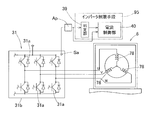
- the motor control device is a control device for controlling the motor 6 of an electric vehicle having a motor 6 for driving the wheel 2, and the electric vehicle is an ECU 21 that is an electric control unit for controlling the entire vehicle.
- a temperature sensor Sa that detects the temperature Tc of the inverter 31 is provided in the inverter 31, and a plurality of threshold values are set for the temperature Tc detected by the temperature sensor Sa, and are divided by each threshold value.
- the “electric vehicle” in the present invention includes a hybrid vehicle using an engine.
- the temperature sensor Sa always detects the temperature Tc of the inverter 31. For example, when an electric vehicle is operated in a state where high torque is continuously generated on a hill or the like, the temperature Tc of the inverter 31 rises and the temperature of the motor coil 78 rises. Since the temperature detection of the inverter 31 by the temperature sensor Sa has poor responsiveness, a plurality of threshold values are set for the temperature Tc, and different current limiting conditions are set for each temperature region divided by each threshold value. That is, when the detected temperature Tc is relatively low, the current limiting condition is relaxed, and the current limiting condition is more strongly regulated as the detected temperature Tc becomes higher.
- the inverter limiting means 95 performs control to limit the current command given to the inverter 31 in accordance with the current limiting condition in the temperature region including the detected temperature Tc. Specifically, control is performed to change one or both of the duty ratio and the number of pulses. For example, the duty ratio indicating the ON time of the pulse with respect to the switching period is made smaller than the set duty ratio to lower the effective voltage value, or the switching period is set to the same period to generate unequal width pulses. Thus, it is possible to limit the current command given to the inverter 31. In this way, by limiting the current command given to the inverter 31, it is possible to finely control the temperature of the inverter 31, and to prevent changes in characteristics of the inverter 31, damage, and a decrease in inverter life. As a result, it is possible to prevent the insulation performance of the motor coil from being deteriorated and to prevent the motor from being unable to be driven.
- the inverter limiting means 95 sets an allowable upper limit of the inverter temperature time change dTc / dt according to each divided temperature region. It may be changed.
- the allowable upper limit of the time variation dTc / dt of the inverter temperature according to each temperature region thus divided, the temperature of the inverter 31 can be finely managed. For example, when the detected temperature Tc is relatively low, even if the degree of change in the temperature Tc is steep, the inverter 31 will not be damaged immediately, so the allowable upper limit of dTc / dt is relaxed. .
- the inverter limiting means 95 decreases the allowable upper limit of the time change dTc / dt of the inverter temperature obtained by differentiating the temperature Tc with respect to time t from the low temperature side to the high temperature side for each temperature region including the detected temperature Tc. You may set so that it becomes.
- the time change dTc / dt of the inverter temperature the temperature of the inverter 31 can be easily and accurately controlled. That is, when the inverter temperature Tc is low, the semiconductor switching element will not be damaged immediately, so that even if the temperature detection response is poor, the temperature Tc can be allowed to rise sharply.
- the semiconductor switching element is likely to be damaged, so that the temperature Tc is strongly regulated so as not to increase rapidly. It is also possible to divide the temperature region divided by each threshold value more finely and reduce the allowable upper limit of dTc / dt linearly toward the high temperature side. In this case, the temperature control of the inverter 31 can be performed more finely.
- the inverter limiting means 95 may limit the dTc / dt by controlling the current value of the motor 6.
- the inverter limiting means 95 performs control to limit the current command given to the inverter 31 at a certain inverter temperature Tc
- the time change dTc / dt of the inverter temperature tends to be constant or decreased.
- the control for controlling the current command to the inverter 31 is released without waiting for the actual temperature Tc to decrease.
- the motor 6 is prevented from being suddenly restricted without excessively reducing the motor current.
- the inverter limiting means 95 includes a determination unit that determines whether or not the temperature Tc detected by the temperature sensor exceeds each threshold, and the detected temperature Tc exceeds a predetermined threshold among a plurality of thresholds.
- An abnormality reporting means for outputting an abnormality report of the inverter 31 to the ECU 21 when determined by the determination unit may be provided.
- the ECU 21 can appropriately control the entire vehicle by outputting an abnormality report of the inverter 31 to the ECU 21.
- the inverter limiting means 95 may be provided in the ECU 21.
- the motor 6 may be a motor 6 that individually drives the wheels 2 of the electric vehicle. A part or the whole of the motor 6 may constitute an in-wheel motor drive device 8 disposed in the wheel 2.
- the in-wheel motor drive device 8 may include the motor 6, the wheel bearing 4, and the speed reducer 7.
- the wheel bearing 4, the speed reducer 7, and the motor 6 are accompanied by a reduction in the amount of materials used and a high-speed rotation of the motor 6, so that reliability is ensured. Is an important issue.
- the current command given to the inverter 31 is appropriately limited. Can be controlled.
- a reduction gear 7 that reduces the rotation of the motor 6 is provided, and this reduction gear 7 may be a cycloid reduction gear having a high reduction ratio of 4 or more.
- the reduction gear 7 is a cycloid reduction gear and the reduction ratio is increased to 4 or more, for example, the motor 6 can be downsized and the apparatus can be downsized.
- the reduction ratio is increased, the motor 6 that rotates at high speed is used.
- the inverter 31 can be prevented from being damaged, and the control characteristics of the motor drive can be prevented and the motor drive can be disabled. it can.
- FIG. 1 is a block diagram of a conceptual configuration showing an electric vehicle according to a first embodiment of the present invention in a plan view. It is a block diagram which shows conceptual composition, such as a control apparatus of the drive motor of the same electric vehicle. It is a block diagram which shows schematic structure of the inverter of the same electric vehicle. It is a block diagram of the control system of the electric vehicle.
- FIG. 10 is a partial enlarged cross-sectional view of FIG. 9. It is a block diagram of conceptual composition, such as ECU of an electric vehicle concerning a 2nd embodiment of this invention.
- the motor control device is mounted on an electric vehicle.
- This electric vehicle is a four-wheeled vehicle in which the wheels 2 that are the left and right rear wheels of the vehicle body 1 are driving wheels and the wheels 3 that are the left and right front wheels are steering wheels of driven wheels.
- the wheels 2 and 3 serving as driving wheels and driven wheels both have tires and are supported by the vehicle body 1 via wheel bearings 4 and 5, respectively.
- the wheel bearings 4 and 5 are given the abbreviation “H / B” of the hub bearing in FIG.
- the left and right wheels 2, 2 serving as driving wheels are driven by independent traveling motors 6, 6, respectively.
- the rotation of the motor 6 is transmitted to the wheel 2 via the speed reducer 7 and the wheel bearing 4.
- the motor 6, the speed reducer 7, and the wheel bearing 4 constitute an in-wheel motor drive device 8 that is one assembly part, and the in-wheel motor drive device 8 is partially or entirely inside the wheel 2. Placed in.
- the in-wheel motor drive device 8 is also referred to as an in-wheel motor unit.
- the motor 6 may directly rotate and drive the wheels 2 without using the speed reducer 7.
- Each wheel 2, 3 is provided with an electric brake 9, 10.
- Wheels 3 and 3 which are steering wheels serving as left and right front wheels can be steered via a steering mechanism 11 and are steered by a steering mechanism 12.
- the steering mechanism 11 is a mechanism that changes the angle of the left and right knuckle arms 11b that hold the wheel bearings 5 by moving the tie rod 11a to the left and right.
- An EPS (electric power steering) motor 13 is driven by a command from the steering mechanism 12. It is driven and moved left and right via a rotation / linear motion conversion mechanism (not shown).
- the steering angle is detected by the steering angle sensor 15, and the sensor output is output to the ECU 21, and the information is used for acceleration / deceleration commands for the left and right wheels.
- the control device U ⁇ b> 1 includes an ECU 21 that is an electric control unit that controls the entire automobile, and an inverter device 22 that controls the traveling motor 6 in accordance with a command from the ECU 21.
- the ECU 21, the inverter device 22, and the brake controller 23 are mounted on the vehicle body 1.
- the ECU 21 includes a computer, a program executed by the computer, various electronic circuits, and the like.
- the ECU 21 is roughly divided into a drive control unit 21a and a general control unit 21b when classified roughly by function.
- the drive control unit 21a gives the left and right wheel motors 6 and 6 the acceleration command output from the accelerator operation unit 16, the deceleration command output from the brake operation unit 17, and the turning command output from the steering angle sensor 15.
- the given acceleration / deceleration command is generated and output to the inverter device 22.
- the drive control unit 21a outputs an acceleration / deceleration command to be output, information on the tire rotation speed obtained from the rotation sensor 24 provided on the wheel bearings 4 and 5 of the wheels 2 and 3, You may have the function to correct
- the accelerator operation unit 16 includes an accelerator pedal and a sensor 16a that detects the amount of depression and outputs the acceleration command.
- the brake operation unit 17 includes a brake pedal and a sensor 17a that detects the amount of depression and outputs the deceleration command.
- the general control unit 21b of the ECU 21 processes a function of outputting a deceleration command output from the brake operation unit 17 to the brake controller 23, a function of controlling various auxiliary machine systems 25, and an input command from the console operation panel 26.
- the auxiliary machine system 25 is, for example, an air conditioner, a light, a wiper, a GPS, an airbag or the like, and is shown here as a representative block.
- the brake controller 23 is means for giving a braking command to the brakes 9 and 10 of the wheels 2 and 3 according to the deceleration command output from the ECU 21.
- the braking command output from the ECU 21 includes a command generated by means for improving the safety of the ECU 21.
- the brake controller 23 includes an antilock brake system.
- the brake controller 23 is configured by an electronic circuit, a microcomputer, or the like.
- the inverter device 22 includes a power circuit unit 28 provided for each motor 6 and a motor control unit 29 that controls the power circuit unit 28.
- the motor control unit 29 may be provided in common for each power circuit unit 28 or may be provided separately, but even if provided in common, each power circuit unit 28. For example, can be controlled independently so that the motor torque is different from each other.
- the motor control unit 29 has a function of outputting information (referred to as “IWM system information”) such as detection values and control values related to the in-wheel motor 8 of the motor control unit 29 to the ECU.
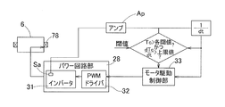
- FIG. 2 is a block diagram showing a conceptual configuration of a control device for a drive motor of the electric vehicle.
- the power circuit unit 28 includes an inverter 31 that converts the DC power of the battery 19 into three-phase AC power that is used to drive the motor 6, and a PWM driver 32 that controls the inverter 31.
- the motor 6 is composed of a three-phase synchronous motor or the like.
- the inverter 31 includes a plurality of semiconductor switching elements 31a, and the PWM driver 32 performs pulse width modulation on the input current command, and gives an on / off command to each of the semiconductor switching elements 31a.
- the motor control unit 29 includes a computer, a program executed on the computer, and an electronic circuit, and includes a motor drive control unit 33 as a basic control unit.
- the motor drive control unit 33 is a unit that converts the current command into a current command in accordance with an acceleration / deceleration command by a torque command or the like given from the ECU that is the host control unit, and gives the current command to the PWM driver 32 of the power circuit unit 28.
- the motor drive control unit 33 obtains a motor current value to be passed from the inverter 31 to the motor 6 from the current detection unit 35 and performs current feedback control.
- the motor drive control unit 33 obtains the rotation angle of the rotor of the motor 6 from the angle sensor 36 and performs vector control.
- the motor control unit 29 configured as described above is provided with the following inverter limiting means 95 and abnormality report means 41, and the ECU 21 is provided with an abnormality display means 42.
- the inverter 31 is provided with a temperature sensor Sa that detects the temperature Tc of the inverter 31.
- the inverter limiting means 95 limits the current command given to the inverter 31, and includes a determination unit 39 and a current control unit 40 which will be described later.
- a current control unit 40 As shown in FIG. 5A, is set a plurality of threshold values with temperature Tc detected by the temperature sensor Sa (Fig. 2) (T 1 In this example, T 2, T 3, T 4) is, the threshold values T 1 ⁇ T 4 for each temperature region Ar @ 1 ⁇ Ar4 segmented by being set different current limiting condition each other.
- the current control unit 40 of the inverter limiting means 95 limits the current command given to the inverter 31 according to the current limiting conditions of the temperature regions Ar1 to Ar4 including the detected temperature Tc.
- the current limiting condition in this example is to provide an upper limit (allowable upper limit) for the time change dTc / dt of the inverter temperature obtained by differentiating the temperature Tc with respect to time t.
- an allowable upper limit of dTc / dt is set for each of the divided temperature regions Ar1 to Ar4.
- the detection value detected by the temperature sensor Sa is amplified by the amplifier Ap.
- the time variation dTc / dt of the inverter temperature by the current control unit 40 can be limited by constantly monitoring dTc / dt based on the value input from the amplifier Ap.
- the threshold value is the threshold value T 1 of the low-temperature side is set.
- An upper limit value of dTc / dt is set in the temperature region Ar1 including the detected temperature Tc.
- the greater than T 1 T 2 temperatures below Tc is detected step, a small threshold T 2 is set to be larger than the threshold value T 3 than the threshold T 1.
- the upper limit value of dTc / dt in the temperature region Ar2 including the detected temperature Tc is set smaller than the upper limit value of dTc / dt in the temperature region Ar1.
- the inverter limiting means 95 changes the allowable upper limit of dTc / dt according to the divided temperature regions Ar1 to Ar4 when the time variation dTc / dt of the inverter temperature is positive.
- the inverter limiting means 95 increases the upper limit value of the time variation dTc / dt of the inverter temperature from the low temperature side to the high temperature side for each temperature region Ar1 to Ar4 including the detected temperature Tc. It is set to decrease step by step.
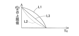
- the temperature region divided by each threshold value is divided more finely, and as shown by the curve L1 in FIG. 5B, the upper limit value of dTc / dt is increased to a convex quadratic function curve.
- the upper limit value of dTc / dt may be reduced to a concave quadratic function curve as shown by the curve L2.
- the upper limit value of dTc / dt may be decreased linearly toward the high temperature side. In these cases, the temperature management of the inverter 31 can be performed more finely than in the case of FIG. 5A.
- the upper limit value of dTc / dt is set as shown by the solid curve L1
- the inverter temperature Tc can be easily allowed to rise sharply until the high temperature side temperature Tc is reached. It becomes easy to perform current control without any trouble.
- a thermistor is used as the temperature sensor Sa.
- the temperature Tc of the inverter 31 can be detected by fixing this thermistor to a substrate 31 b on which a plurality of semiconductor switching elements 31 a are mounted.
- the thermistor may be fixed to the semiconductor switching element 31a itself.
- the detection value detected by the thermistor is amplified by the amplifier Ap, and this amplification value is determined by the determination unit 39.
- the determination unit 39 always determines whether or not the temperature Tc detected by the temperature sensor Sa has exceeded the upper limit value of the temperature region including the detected temperature Tc. It is always determined whether or not each of the threshold values T 1 to T 4 is exceeded. At the same time, the determination unit 39 always determines whether or not the time change dTc / dt of the inverter temperature exceeds the upper limit value of the temperature region including the detected temperature Tc.
- Each of the threshold values T 1 to T 4 may be divided according to the number of threshold values T 1 to T 4 by giving a range to the operation guarantee temperature of the semiconductor switching element 31a to be used, experiment, simulation, etc. Thus, it is appropriately determined based on the relationship between the temperature and time of the inverter 31 that causes the characteristic change of the inverter 31.
- the obtained threshold values are stored as a table in a rewritable storage means (not shown).
- the current control unit 40 is connected via the motor drive control unit 33 so as to limit the current command given to the inverter 31.
- the motor drive control unit 33 converts the current command into a current command in accordance with an acceleration / deceleration command from the ECU 21 and gives the current command to the PWM driver 32, but receives a command from the current control unit 40 and limits the current command. give.
- the current control unit 40 performs control to change either or both of the duty ratio and the number of pulses. For example, the duty ratio indicating the ON time of the pulse with respect to the switching period is lowered by several tens of percent from the set duty ratio to lower the effective voltage value, or the switching period is set to the same period and the unequal width pulse Can generate a restriction on the current command given to the inverter 31. Thereby, the time change dTc / dt of the inverter temperature tends to be constant or decreased.
- dTc / dt When such a tendency of dTc / dt is recognized, that is, when the time change dTc / dt of the inverter temperature becomes 0 or less, the current limitation to the inverter 31 is released without waiting for the actual temperature Tc to decrease. . For this reason, the motor 6 is prevented from being suddenly restricted without excessively reducing the motor current.
- the dTc / dt being 0 or less is synonymous with the fact that the gradient of the temperature Tc in an arbitrary minute time is 0 or less.
- the temperature of the inverter 31 does not drop suddenly, and if the current command to the inverter 31 is limited until the temperature drops to some extent and the motor current is reduced, the driving of the vehicle may be hindered due to the sudden drive limitation of the motor 6.
- the restriction of the motor current flowing to the motor 6 is released by detecting the sign of the temperature drop as described above and releasing the restriction of the current to the inverter 31, the problem due to the sudden drive restriction of the motor 6 is also avoided. Is done.
- the detected temperature Tc is then a temperature equal to or higher than a threshold value in a temperature region including the temperature Tc, and dTc / If dt exceeds the upper limit value of the temperature range in which the detected temperature Tc is included, control for limiting the current command to the inverter 31 again is performed. Therefore, when the time change dTc / dt of the inverter temperature becomes 0 or less, overload can be reliably prevented even if the control for limiting the current command to the inverter 31 is canceled.
- FIG. 6A and FIG. 6B are graphs showing the relationship between the temperature Tc of the inverter 31 of this electric vehicle and the time t, respectively.
- the determination unit 39 exceeds the thresholds T 1 temperature Tc of the inverter 31, and determines that dTc / dt exceeds the upper limit.
- the current control unit 40 commands the power circuit unit 28 via the motor drive control unit 33 so as to limit the current command to the inverter 31.
- the motor drive control unit 33 gives a current command to the PWM driver 32 of the power circuit unit 28 in accordance with the command given from the current control unit 40.
- the power circuit unit 28 reduces the current supplied to the motor 6.
- the current control unit 40 receives the determination result by the determination unit 39 and limits the current command to the inverter 31 via the motor drive control unit 33. Command to 28.
- the current control unit 40 commands the power circuit unit 28 via the motor drive control unit 33 so as to limit the current command to the inverter 31 as described above.
- dTc / dt becomes “0” (temperature Tc is constant) at time t ⁇ b> 4
- the current control unit 40 releases the current limitation to the inverter 31.
- the detected temperature Tc is at or above the threshold value in the temperature region including the temperature Tc, and dTc / dt is detected. If the upper limit value of the temperature range including the temperature Tc is exceeded, control for limiting the current command to the inverter 31 is performed again.
- the abnormality reporting unit 41 outputs abnormality occurrence information to the ECU 21 when the determination unit 39 determines that the temperature Tc exceeds a predetermined threshold value (for example, T 2 ) among a plurality of threshold values.
- a predetermined threshold value for example, T 2
- the abnormality display means 42 provided in the ECU 21 is means for receiving the abnormality occurrence information of the inverter 31 output from the abnormality report means 41 and causing the display device 27 in the driver's seat to perform a display notifying the abnormality.
- the display on the display device 27 is a display using characters or symbols, for example, an icon.
- the temperature sensor Sa constantly detects the temperature Tc of the inverter 31. For example, when an electric vehicle is operated in a state where high torque is generated continuously on a slope or the like, the temperature Tc of the inverter 31 rises and the temperature of the motor coil 78 (FIG. 7) rises. Since the temperature detection of the inverter 31 by the temperature sensor Sa has poor responsiveness, a plurality of threshold values are set for the temperature Tc, and different current limiting conditions are set for each temperature region divided by each threshold value.
- the current limit condition is relaxed, that is, the upper limit value of dTc / dt is increased, and the detected temperature Tc becomes higher as the detected temperature Tc becomes higher.
- the upper limit value of / dt is strongly regulated.
- the inverter limiting means 95 performs control to limit the current command given to the inverter 31 in accordance with the current limiting condition in the temperature region including the detected temperature Tc. For example, the duty ratio indicating the ON time of the pulse with respect to the switching period is made smaller than the set duty ratio to lower the effective voltage value, or the switching period is made the same period to generate unequal width pulses. Thus, it is possible to limit the current command given to the inverter 31. By limiting the current command given to the inverter 31 in this manner, the temperature of the inverter 31 can be finely controlled, and changes in characteristics of the inverter 31, damage, and a decrease in inverter life can be prevented. As a result, it is possible to prevent the insulation performance of the motor coil 78 (FIG. 7) from being deteriorated, and to prevent the motor 6 from being unable to be driven.
- the motor coil 78 FIG. 7
- the inverter limiting means 95 changes the allowable upper limit of the time change dTc / dt of the inverter temperature according to each divided temperature region when the time change dTc / dt of the inverter temperature obtained by differentiating the temperature Tc with respect to the time t is positive. I am going to do it.
- the allowable upper limit of the time variation dTc / dt of the inverter temperature according to each temperature region thus divided the temperature of the inverter 31 can be finely managed. For example, when the detected temperature Tc is relatively low, even if the degree of change in the temperature Tc is steep, the inverter 31 will not be damaged immediately, so the allowable upper limit of dTc / dt is relaxed. .
- the allowable upper limit of dTc / dt is set so that the allowable upper limit of dTc / dt is decreased from the low temperature side to the high temperature side for each temperature region in which the detected temperature Tc is included. can do. That is, when the inverter temperature Tc is low, the semiconductor switching element 31a is not immediately damaged, and therefore, it is possible to allow the temperature Tc to rise sharply even when the temperature detection response is poor. When the inverter temperature Tc is high, the semiconductor switching element 31a is liable to be damaged, so that the temperature Tc is strongly regulated so as not to increase rapidly. It is also possible to divide the temperature region divided by each threshold value more finely and reduce the allowable upper limit of dTc / dt linearly toward the high temperature side. In this case, the temperature control of the inverter 31 can be performed more finely.
- the inverter limiting means 95 is provided in the motor control unit 29 of the inverter device 22 and the detected temperature can be determined at a location close to the motor 6, it is advantageous in terms of wiring, and quicker control than in the case where it is provided in the ECU 21 can be performed. In this way, problems in running the vehicle can be avoided quickly. Further, it is possible to reduce the burden on the ECU 21 that is becoming more complicated due to higher functions.
- the ECU 21 is a device that controls the vehicle in general, when the inverter control means 95 in the inverter device 22 detects a temperature abnormality of the inverter 31, the ECU 21 outputs an abnormality report of the inverter 31 to the ECU 21. Thus, appropriate control of the entire vehicle can be performed. Further, the ECU 21 is a higher-level control unit that gives a drive command to the inverter device 22, and after the emergency control by the inverter device 22, the ECU 21 can perform more appropriate control of the subsequent drive.
- the in-wheel motor drive device 8 includes a reduction gear 7 interposed between the wheel bearing 4 and the motor 6, and the wheel 2 (drive wheel supported by the wheel bearing 4 ( The hub in FIG. 2) and the rotation output shaft 74 of the motor 6 (FIG. 7) are connected coaxially.
- the reduction gear 7 may have a reduction ratio of 4 or more.
- the speed reducer 7 is a cycloid speed reducer, in which eccentric portions 82a and 82b are formed on a rotational input shaft 82 that is coaxially connected to a rotational output shaft 74 of the motor 6, and bearings 85 are provided on the eccentric portions 82a and 82b, respectively.
- the curvilinear plates 84a and 84b are attached to the discs, and the eccentric motion of the curvilinear plates 84a and 84b is transmitted to the wheel bearing 4 as rotational motion.
- the side closer to the outer side in the vehicle width direction of the vehicle when attached to the vehicle is referred to as the outboard side, and the side closer to the center of the vehicle is referred to as the inboard side.
- the wheel bearing 4 includes an outer member 51 in which a double row rolling surface 53 is formed on the inner periphery, an inner member 52 in which a rolling surface 54 facing each of the rolling surfaces 53 is formed on the outer periphery, and these
- the outer member 51 and the inner member 52 are composed of double-row rolling elements 55 interposed between the rolling surfaces 53 and 54 of the inner member 52.
- the inner member 52 also serves as a hub for attaching the drive wheels.
- the wheel bearing 4 is a double-row angular ball bearing, and the rolling elements 55 are made of balls and are held by a cage 56 for each row.
- the rolling surfaces 53 and 54 have a circular arc cross section, and the rolling surfaces 53 and 54 are formed so that the contact angles are aligned with the back surface.
- An end on the outboard side of the bearing space between the outer member 51 and the inner member 52 is sealed with a seal member 57.
- the outer member 51 is a stationary raceway, has a flange 51a attached to the housing 83b on the outboard side of the speed reducer 7, and is formed as an integral part as a whole.
- the flange 51a is provided with bolt insertion holes 64 at a plurality of locations in the circumferential direction.
- the housing 83b is provided with a bolt screw hole 94 whose inner periphery is threaded at a position corresponding to the bolt insertion hole 64.
- the outer member 51 is attached to the housing 83b by screwing the mounting bolt 65 inserted into the bolt insertion hole 94 into the bolt screwing hole 94.
- the inner member 52 is a rotating raceway, and the outboard side member 59 having a hub flange 59a for wheel mounting and the outboard side member 59 are fitted to the inner periphery of the outboard side member 59.
- the inboard side material 60 is integrated with the outboard side material 59 by fastening.
- the rolling surface 54 of each row is formed in each of the outboard side material 59 and the inboard side material 60.
- a through hole 61 is provided in the center of the inboard side member 60.
- the hub flange 59a is provided with press-fit holes 67 for hub bolts 66 at a plurality of locations in the circumferential direction.
- a cylindrical pilot portion 63 that guides driving wheels and braking components (not shown) protrudes toward the outboard side.
- a cap 68 that closes the outboard side end of the through hole 61 is attached to the inner periphery of the pilot portion 63.
- the motor 6 is a radial gap type IPM motor (that is, an embedded magnet type synchronous motor) in which a radial gap is provided between a motor stator 73 fixed to a cylindrical motor housing 72 and a motor rotor 75 attached to the rotation output shaft 74. ).
- the rotation output shaft 74 is cantilevered by two bearings 76 on the cylindrical portion of the housing 83 a on the inboard side of the speed reducer 7.
- FIG. 8 shows a cross-sectional view of the motor (cross-section along VIII-VIII in FIG. 7).
- the rotor 75 of the motor 6 includes a core portion 79 made of a soft magnetic material and a permanent magnet 80 built in the core portion 79.
- the permanent magnets 80 are arranged so that two adjacent permanent magnets face each other in a cross-sectional shape on the same circumference in the rotor core portion 79.
- the permanent magnet 80 is a neodymium magnet.
- the stator 73 includes a core part 77 and a coil 78 made of a soft magnetic material.
- the core portion 77 has a ring shape with an outer peripheral surface having a circular cross section, and a plurality of teeth 77a protruding inward on the inner peripheral surface are formed side by side in the circumferential direction.
- the coil 78 is wound around the teeth 77 a of the stator core portion 77.
- the motor 6 is provided with an angle sensor 36 that detects a relative rotation angle between the motor stator 73 and the motor rotor 75.
- the angle sensor 36 detects and outputs a signal representing a relative rotation angle between the motor stator 73 and the motor rotor 75, and an angle calculation circuit 71 that calculates an angle from the signal output from the angle sensor body 70.
- the angle sensor main body 70 includes a detected portion 70a provided on the outer peripheral surface of the rotation output shaft 74, and a detecting portion 70b provided in the motor housing 72 and disposed in close proximity to the detected portion 70a, for example, in the radial direction. Become.
- the detected part 70a and the detecting part 70b may be arranged close to each other in the axial direction.
- the angle sensor 36 may be a resolver.
- each phase of each wave of alternating current flowing through the coil 78 of the motor stator 73 based on the relative rotation angle between the motor stator 73 and the motor rotor 75 detected by the angle sensor 36. Is controlled by the motor drive control unit 33 of the motor control unit 29.
- the motor current wiring of the in-wheel motor driving device 8 and various sensor system and command system wiring are collectively performed by a connector 99 provided in the motor housing 72 or the like.
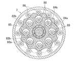
- the speed reducer 7 is a cycloid speed reducer as described above, and the two curved plates 84a and 84b formed by the wavy trochoid curve having a gentle outer shape as shown in FIG.
- the shaft 82 is attached to each eccentric part 82a, 82b.
- a plurality of outer pins 86 for guiding the eccentric movements of the curved plates 84a and 84b on the outer peripheral side are provided across the housing 83b, and a plurality of inner pins 88 attached to the inboard side member 60 of the inner member 2 are provided.
- the curved plates 84a and 84b are engaged with a plurality of circular through holes 89 provided in the inserted state.
- the rotation input shaft 82 is spline-coupled with the rotation output shaft 74 of the motor 6 and rotates integrally.
- the rotary input shaft 82 is supported at both ends by two bearings 90 on the inboard side housing 83a and the inner diameter surface of the inboard side member 60 of the inner member 52.
- the curved plates 84a and 84b attached to the rotation input shaft 82 that rotates together with the motor 6 perform an eccentric motion.
- the eccentric motions of the curved plates 84 a and 84 b are transmitted to the inner member 52 as rotational motion by the engagement of the inner pins 88 and the through holes 89.
- the rotation of the inner member 52 is decelerated with respect to the rotation of the rotation output shaft 74. For example, a reduction ratio of 10 or more can be obtained with a single-stage cycloid reducer.
- the two curved plates 84a and 84b are attached to the eccentric portions 82a and 82b of the rotary input shaft 82 so as to cancel out the eccentric motion with each other, and are mounted on both sides of the eccentric portions 82a and 82b.
- a counterweight 91 that is eccentric in the direction opposite to the eccentric direction of the eccentric portions 82a and 82b is mounted so as to cancel the vibration caused by the eccentric movement of the curved plates 84a and 84b.
- bearings 92 and 93 are mounted on the outer pins 86 and the inner pins 88, and outer rings 92a and 93a of the bearings 92 and 93 are respectively connected to the curved plates 84a and 84b. It comes into rolling contact with the outer periphery and the inner periphery of each through-hole 89. Therefore, the contact resistance between the outer pin 86 and the outer periphery of each curved plate 84a, 84b and the contact resistance between the inner pin 88 and the inner periphery of each through hole 89 are reduced, and the eccentric motion of each curved plate 84a, 84b is smooth. Can be transmitted to the inner member 52 as a rotational motion.
- the wheel bearing 4 of the in-wheel motor drive device 8 is attached to the vehicle body via a suspension device (not shown) such as a knuckle on the outer periphery of the housing 83b of the speed reducer 7 or the housing 72 of the motor 6. Fixed.
- the wheel bearing 4, the speed reducer 7, and the motor 6 are accompanied by a reduction in the amount of materials used and a high-speed rotation of the motor 6, so that reliability is ensured. Is an important issue.
- the current command given to the inverter 31 is appropriately limited. Can be controlled.
- the motor 6 can be downsized and the device can be downsized.
- the reduction ratio is increased, the motor 6 that rotates at high speed is used.
- the characteristic change or damage of the inverter 31 can be prevented, and the change of the motor drive control characteristic or the inability to drive the motor can be prevented. be able to.
- the inverter limiting means 95 may be provided in the ECU 21 that is an electric control unit that controls the entire vehicle.
Landscapes
- Engineering & Computer Science (AREA)
- Power Engineering (AREA)
- Mechanical Engineering (AREA)
- Transportation (AREA)
- Life Sciences & Earth Sciences (AREA)
- Sustainable Development (AREA)
- Sustainable Energy (AREA)
- Combustion & Propulsion (AREA)
- Chemical & Material Sciences (AREA)
- Electric Propulsion And Braking For Vehicles (AREA)
- Inverter Devices (AREA)
- Arrangement Or Mounting Of Propulsion Units For Vehicles (AREA)
- Retarders (AREA)
- Control Of Ac Motors In General (AREA)
Abstract
インバータ(31)に、このインバータ(31)の温度(Tc)を検出する温度センサ(Sa)を設ける。この温度センサ(Sa)で検出される温度(Tc)に対し複数の閾値が設定され、各閾値で区分される温度領域毎に、互いに異なる電流制限条件が設定され、検出される温度(Tc)の含まれる温度領域の電流制限条件に応じてインバータ(31)に与える電流指令に制限を加えるインバータ制限手段(95)を設けた。これにより、車両の運転を妨げることなく、インバータ(31)を温度管理して、その過熱による特性変化および損傷を防止すると共にインバータ(31)の寿命の低下を防止する。
Description
本出願は、2011年11月24日出願の特願2011-256140の優先権を主張するものであり、その全体を参照により本願の一部をなすものとして引用する。
この発明は、モータの制御装置に関し、バッテリ駆動、燃料電池駆動、エンジン併用のハイブリッド車等の電気自動車における車輪を駆動するモータの制御装置に関する。
電気自動車では、一般的に同期型のモータや誘導型のモータが用いられ、バッテリの直流電流をインバータで交流電流に変換してモータの駆動が行われる。インバータは、主に複数の半導体スイッチング素子で構成されるが、モータ駆動のための大電流を流すため、発熱が大きい。半導体スイッチング素子は、温度による特性変化が大きく、また、過熱により損傷することがあるため、インバータには一般的に冷却手段が設けられている。なお、従来、インホイールモータ駆動装置において、信頼性確保のために、車輪用軸受、減速機、およびモータ等の温度を測定して過負荷を監視し、温度測定値に応じてモータの駆動電流の制限や、モータ回転数を低下させるものが提案されている(例えば、特許文献1)。
電気自動車のインバータは、前記のように冷却手段が設けられていて、通常の運転では過昇温が防止される。しかし、坂道等において、連続して高トルク発生状態で運転した場合、流れる電流が大きくなるため、過熱により特性が変化したり、損傷したりする恐れがある。また半導体スイッチング素子の温度が過度に上昇することで、インバータの寿命を低下させる可能性がある。このようなインバータの特性変化、損傷、インバータ寿命の低下は、モータ駆動の制御特性の変化や、モータ駆動の不能を招く。また、インバータ温度を測定して過負荷を監視し、モータの駆動電流を駆動制限する場合、車両の運転が急激に妨げられるおそれがある。
この発明の目的は、車両の運転を急激に妨げることなく、インバータの過熱による特性変化および損傷を防止すると共にインバータ寿命の低下を防止することができ、適切な対処が迅速に行えるモータの制御装置を提供することである。以下、この発明の概要について、実施形態を示す図面中の符号を用いて説明する。
この発明のモータの制御装置は、車輪2を駆動するモータ6を有する電気自動車の前記モータ6を制御する制御装置であって、前記電気自動車は、車両全般を制御する電気制御ユニットであるECU21と、バッテリの直流電力を前記モータ6の駆動に用いる交流電力に変換するインバータ31を含むパワー回路部28と、前記ECU21の制御に従って少なくとも前記パワー回路部28を制御するモータコントロール部29とを有するインバータ装置22とを備え、前記インバータ31に、このインバータ31の温度Tcを検出する温度センサSaを設け、前記温度センサSaで検出される温度Tcに対し複数の閾値が設定され、各閾値で区分される温度領域毎に、互いに異なる電流制限条件を設定し、検出される温度Tcの含まれる前記温度領域の前記電流制限条件に応じてインバータ31に与える電流指令に制限を加えるインバータ制限手段95を有する。なお、この発明における「電気自動車」は、エンジン併用のハイブリッド車も含む。
この構成によると、温度センサSaは、インバータ31の温度Tcを常時検出する。例えば、坂道等において連続して高トルク発生状態で電気自動車を運転した場合、インバータ31の温度Tcが上昇すると共に、モータコイル78の温度が上昇する。温度センサSaによるインバータ31の温度検出は、応答性が悪いことから、温度Tcに対し複数の閾値が設定され、各閾値で区分けされる温度領域毎に、互いに異なる電流制限条件が設定される。つまり、検出される温度Tcが比較的低温のときは、電流制限条件を緩和し、検出される温度Tcが高温になる程、電流制限条件を強く規制する。
インバータ制限手段95は、検出される温度Tcの含まれる前記温度領域の前記電流制限条件に応じてインバータ31に与える電流指令に制限を加える制御を行う。具体的には、デューティ比とパルス数のいずれか一方または両方を変更する制御を行う。例えば、スイッチング周期に対するパルスのON時間を表す前記デューティ比を、設定されたデューティ比よりも小さくして電圧実効値を低くしたり、スイッチング周期を同一周期にしておいて不等幅パルスを発生させることで、インバータ31に与える電流指令に制限を加え得る。このように、インバータ31に与える電流指令に制限を加えることで、インバータ31を木目細かく温度管理することができ、インバータ31の特性変化、損傷、インバータ寿命の低下を防止することができる。これによりモータコイルの絶縁性能の劣化を防止でき、モータが駆動不能に陥ることを防止できるため、車両の運転が急激に妨げられることを回避することができる。
前記インバータ制限手段95は、温度Tcを時間tで微分したインバータ温度の時間変化dTc/dtが正のとき、区分された各温度領域に応じて、インバータ温度の時間変化dTc/dtの許容上限を変更するものとしても良い。このように区分された各温度領域に応じて、インバータ温度の時間変化dTc/dtの許容上限を変更することで、インバータ31を木目細かく温度管理することができる。例えば、検出される温度Tcが比較的低温のときは、温度Tcが変化する度合いが急峻であったとしても、インバータ31が直ぐに損傷等することはないため、dTc/dtの許容上限を緩和する。逆に、検出される温度Tcが高温になる程、温度Tcが変化する度合いが緩やかであっても、インバータ31の特性変化、損傷、インバータ寿命の低下に繋がる。したがって、区分された各温度領域に応じて、インバータ温度の時間変化dTc/dtの許容上限を変更し、インバータ31を温度管理することで、インバータ31の損傷等を防止することができる。
前記インバータ制限手段95は、温度Tcを時間tで微分したインバータ温度の時間変化dTc/dtの許容上限を、検出される温度Tcの含まれる各温度領域毎に低温側から高温側に向けて小さくなるように設定しても良い。このようにインバータ温度の時間変化dTc/dtを設定することで、インバータ31を容易に且つ精度良く温度管理することができる。すなわち、インバータ温度Tcが低いときには、半導体スイッチング素子が直ぐに損傷等することはないため、温度検出の応答性が悪い場合であっても温度Tcが急峻に上昇することを許容できる。インバータ温度Tcが高いときには、半導体スイッチング素子の損傷等が起き易いため、温度Tcが急激に上昇しないように強く規制する。各閾値で区分される温度領域をより細かく区分し、dTc/dtの許容上限を高温側に向けて直線的に減少させることも可能である。この場合、インバータ31の温度管理をさらに木目細かく行うことができる。
前記インバータ制限手段95は、モータ6の電流値を制御することにより、前記dTc/dtを制限するようにしても良い。あるインバータ温度Tcのとき、インバータ制限手段95がインバータ31に与える電流指令に制限を加える制御を行うと、インバータ温度の時間変化dTc/dtは一定または低下する傾向を示す。このようなdTc/dtの傾向が認識されたとき、つまりインバータ温度の時間変化が0以下になると、実際の温度Tcが下がるのを待つことなく、インバータ31への電流指令を制御する制御を解除するので、モータ電流を低減し過ぎることがなくモータ6の急激な駆動制限が防止される。
インバータ制限手段95の制御解除によって、インバータ31の温度Tcが上がり始めても、そのときは、検出される温度Tcが、この温度Tcの含まれる温度領域における閾値以上であり、且つ、dTc/dtが、検出される前記温度Tcの含まれる温度領域の上限値を超えれば、再度インバータ31への電流指令を制限する制御を行う。そのため、インバータ温度の時間変化dTc/dtが0以下になったときに、インバータ31への電流指令を制限する制御を解除しても過負荷の確実な防止が行える。したがって、インバータ31の過熱による損傷等を防止し、モータ駆動の制御特性の変化や、モータ駆動の不能を防止することができる。
前記インバータ制限手段95は、温度センサで検出される温度Tcが各閾値を超えるか否かを判定する判定部を有し、検出される温度Tcが複数の閾値のうち定められた閾値を超えたと判定部で判定されたとき、ECU21にインバータ31の異常報告を出力する異常報告手段を設けても良い。この場合、ECU21にインバータ31の異常報告を出力することで、ECU21により車両全体の適切な制御が行える。場合によっては、インバータ制限手段95がECU21内に有するものであっても良い。
前記モータ6は、前記電気自動車の車輪2を個別に駆動するモータ6であっても良い。前記モータ6の一部または全体が車輪2内に配置されるインホイールモータ駆動装置8を構成するものであっても良い。前記インホイールモータ駆動装置8は、前記モータ6と車輪用軸受4と減速機7とを含むものであっても良い。インホイールモータ駆動装置8の場合、コンパクト化を図る結果、車輪用軸受4、減速機7、およびモータ6は、材料使用量の削減、モータ6の高速回転化を伴うため、これらの信頼性確保が重要な課題となる。特に、インバータ31の温度Tcを検出し、インバータ31の過熱による異常、例えば、半導体スイッチング素子が過熱することに起因する熱暴走等を常時監視することで、インバータ31に与える電流指令を適切に制限する制御を行うことができる。
前記モータ6の回転を減速する減速機7を備え、この減速機7は、4以上の高減速比を有するサイクロイド減速機であっても良い。減速機7をサイクロイド減速機として減速比を例えば4以上に高くした場合、モータ6の小型化を図り、装置のコンパクト化を図ることができる。減速比を高くした場合、モータ6は高速回転するものが用いられる。モータ6が高速回転状態のとき、インバータ31の損傷等を防止し、モータ駆動の制御特性の変化や、モータ駆動の不能を防止できるため、車両が急激に走行不能に陥ることを回避することができる。
請求の範囲および/または明細書および/または図面に開示された少なくとも2つの構成のどのような組合せも、本発明に含まれる。特に、請求の範囲の各請求項の2つ以上のどのような組合せも、本発明に含まれる。
この発明は、添付の図面を参考にした以下の好適な実施形態の説明から、より明瞭に理解されるであろう。しかしながら、実施形態および図面は単なる図示および説明のためのものであり、この発明の範囲を定めるために利用されるべきものではない。この発明の範囲は添付の請求の範囲によって定まる。添付図面において、複数の図面における同一の符号は、同一または相当する部分を示す。
この発明の第1実施形態に係る電気自動車を平面図で示す概念構成のブロック図である。
同電気自動車の駆動モータの制御装置等の概念構成を示すブロック図である。
同電気自動車のインバータの概略構成を示すブロック図である。
同電気自動車の制御系のブロック図である。
インバータ温度と、dTc/dtの上限値との関係を示すグラフである。
各閾値で区分される温度領域をより細かく区分した場合のインバータ温度と、dTc/dtの上限値との関係を示すグラフである。
同電気自動車のインバータ装置のインバータ温度と時間との関係を示すグラフである。
同電気自動車のインバータ装置のインバータ温度と時間との関係を示すグラフである。
同電気自動車におけるインホイールモータ駆動装置の破断正面図である。
図7のVIII-VIII 線断面となるモータ部分の断面図である
図7のIX-IX線断面となる減速機部分の断面図である。
図9の部分拡大断面図である。
この発明の第2実施形態に係る電気自動車のECU等の概念構成のブロック図である。
この発明の第1実施形態を図1ないし図10と共に説明する。この実施形態に係るモータの制御装置は、電気自動車に搭載されている。この電気自動車は、車体1の左右の後輪となる車輪2が駆動輪とされ、左右の前輪となる車輪3が従動輪の操舵輪とされた4輪の自動車である。駆動輪および従動輪となる車輪2,3は、いずれもタイヤを有し、それぞれ車輪用軸受4,5を介して車体1に支持されている。車輪用軸受4,5は、図1ではハブベアリングの略称「H/B」を付してある。駆動輪となる左右の車輪2,2は、それぞれ独立の走行用のモータ6,6により駆動される。モータ6の回転は、減速機7および車輪用軸受4を介して車輪2に伝達される。これらモータ6、減速機7、および車輪用軸受4は、互いに一つの組立部品であるインホイールモータ駆動装置8を構成しており、インホイールモータ駆動装置8は、一部または全体が車輪2内に配置される。インホイールモータ駆動装置8は、インホイールモータユニットとも称される。モータ6は、減速機7を介さずに直接に車輪2を回転駆動するものであっても良い。各車輪2,3には、電動式のブレーキ9,10が設けられている。
左右の前輪となる操舵輪である車輪3,3は、転舵機構11を介して転舵可能であり、操舵機構12により操舵される。転舵機構11は、タイロッド11aを左右移動させることで、車輪用軸受5を保持した左右のナックルアーム11bの角度を変える機構であり、操舵機構12の指令によりEPS(電動パワーステアリング)モータ13を駆動させ、回転・直線運動変換機構(図示せず)を介して左右移動させられる。操舵角は操舵角センサ15で検出し、このセンサ出力はECU21に出力され、その情報は左右輪の加速・減速指令等に使用される。
制御系を説明する。図1に示すように、制御装置U1は、自動車全般の制御を行う電気制御ユニットであるECU21と、このECU21の指令に従って走行用のモータ6の制御を行うインバータ装置22とを有する。前記ECU21と、インバータ装置22と、ブレーキコントローラ23とが、車体1に搭載されている。ECU21は、コンピュータとこれに実行されるプログラム、並びに各種の電子回路等で構成される。
ECU21は、機能別に大別すると駆動制御部21aと一般制御部21bとに分けられる。駆動制御部21aは、アクセル操作部16の出力する加速指令と、ブレーキ操作部17の出力する減速指令と、操舵角センサ15の出力する旋回指令とから、左右輪の走行用モータ6,6に与える加速・減速指令を生成し、インバータ装置22へ出力する。駆動制御部21aは、上記の他に、出力する加速・減速指令を、各車輪2,3の車輪用軸受4,5に設けられた回転センサ24から得られるタイヤ回転数の情報や、車載の各センサの情報を用いて補正する機能を有していても良い。アクセル操作部16は、アクセルペダルとその踏み込み量を検出して前記加速指令を出力するセンサ16aとでなる。ブレーキ操作部17は、ブレーキペダルとその踏み込み量を検出して前記減速指令を出力するセンサ17aとでなる。
ECU21の一般制御部21bは、前記ブレーキ操作部17の出力する減速指令をブレーキコントローラ23へ出力する機能、各種の補機システム25を制御する機能、コンソールの操作パネル26からの入力指令を処理する機能、表示手段27に表示を行う機能などを有する。前記補機システム25は、例えば、エアコン、ライト、ワイパー、GPS、エアバッグ等であり、ここでは代表して一つのブロックとして示す。
ブレーキコントローラ23は、ECU21から出力される減速指令に従って、各車輪2,3のブレーキ9,10に制動指令を与える手段である。ECU21から出力される制動指令には、ブレーキ操作部17の出力する減速指令によって生成される指令の他に、ECU21の持つ安全性向上のための手段によって生成される指令がある。ブレーキコントローラ23は、この他にアンチロックブレーキシステムを備える。ブレーキコントローラ23は、電子回路やマイコン等により構成される。
インバータ装置22は、各モータ6に対して設けられたパワー回路部28と、このパワー回路部28を制御するモータコントロール部29とで構成される。モータコントロール部29は、各パワー回路部28に対して共通して設けられていても、別々に設けられていても良いが、共通して設けられた場合であっても、各パワー回路部28を、例えば互いにモータトルクが異なるように独立して制御可能なものとされる。モータコントロール部29は、このモータコントロール部29が持つインホイールモータ8に関する各検出値や制御値等の各情報(「IWMシステム情報」と称す)をECUに出力する機能を有する。
図2は、この電気自動車の駆動モータの制御装置等の概念構成を示すブロック図である。パワー回路部28は、バッテリ19の直流電力をモータ6の駆動に用いる3相の交流電力に変換するインバータ31と、このインバータ31を制御するPWMドライバ32とで構成される。モータ6は3相の同期モータ等からなる。図3に示すように、インバータ31は、複数の半導体スイッチング素子31aで構成され、PWMドライバ32は、入力された電流指令をパルス幅変調し、前記各半導体スイッチング素子31aにオンオフ指令を与える。
図2に示すように、モータコントロール部29は、コンピュータとこれに実行されるプログラム、および電子回路により構成され、その基本となる制御部としてモータ駆動制御部33を有している。モータ駆動制御部33は、上位制御手段であるECUから与えられるトルク指令等による加速・減速指令に従い、電流指令に変換して、パワー回路部28のPWMドライバ32に電流指令を与える手段である。モータ駆動制御部33は、インバータ31からモータ6に流すモータ電流値を電流検出手段35から得て、電流フィードバック制御を行う。また、モータ駆動制御部33は、モータ6のロータの回転角を角度センサ36から得て、ベクトル制御を行う。
この実施形態では、上記構成のモータコントロール部29に、次のインバータ制限手段95、および異常報告手段41を設け、ECU21に異常表示手段42を設けている。また、インバータ31に、このインバータ31の温度Tcを検出する温度センサSaを設けている。
図2に示すように、インバータ制限手段95は、インバータ31に与える電流指令に制限を加えるものであり、後述する判定部39と、電流制御部40とを有する。図5Aに示すように、温度センサSa(図2)で検出される温度Tcに対し複数の閾値(この例ではT1,T2,T3,T4)が設定され、各閾値T1~T4で区分される温度領域Ar1~Ar4毎に、互いに異なる電流制限条件が設定されている。インバータ制限手段95の電流制御部40は、検出される温度Tcの含まれる前記温度領域Ar1~Ar4の前記電流制限条件に応じてインバータ31に与える電流指令に制限を与える。この例の前記電流制限条件は、温度Tcを時間tで微分したインバータ温度の時間変化dTc/dtに上限値(許容上限)を設けることである。電流制限条件として、区分される温度領域Ar1~Ar4毎に、dTc/dtの許容上限が設定されている。温度センサSaで検出された検出値は、アンプApで増幅される。電流制御部40によるインバータ温度の時間変化dTc/dtの制限は、前記アンプApから入力される値によりdTc/dtを常時監視することで行える。
具体的には、T1以下の温度Tcが検出された段階では、閾値は低温側の閾値T1が設定される。この検出された前記温度Tcの含まれる温度領域Ar1における、dTc/dtの上限値が設定されている。T1より大きくT2以下の温度Tcが検出された段階では、閾値T1よりも大きく閾値T3よりも小さい閾値T2が設定される。この検出された前記温度Tcの含まれる温度領域Ar2における、dTc/dtの上限値は、温度領域Ar1のdTc/dtの上限値よりも小さく設定されている。このようにインバータ制限手段95は、インバータ温度の時間変化dTc/dtが正のとき、区分される温度領域Ar1~Ar4に応じて、dTc/dtの許容上限を変更するものとしている。
図5Aの例では、インバータ制限手段95は、インバータ温度の時間変化dTc/dtの上限値を、検出される温度Tcの含まれる各温度領域Ar1~Ar4毎に低温側から高温側に向けて、段階的に小さくなるように設定している。なお、図5Bに示すように、各閾値で区分される温度領域をより細かく区分し、同図の曲線L1で示すように、dTc/dtの上限値を凸となる二次関数曲線状に高温側に向けて減少させても良いし、曲線L2で示すように、dTc/dtの上限値を凹となる二次関数曲線状に減少させても良い。また、直線L3で示すように、dTc/dtの上限値を高温側に向けて直線状に減少させても良い。これらの場合、インバータ31の温度管理を図5Aの場合よりもさらに木目細かく行うことができる。実線の曲線L1のようにdTc/dtの上限値を設定すると、高温側の温度Tcに至るまではインバータ温度Tcが急峻に上昇することを許容し易くできるため、電流制御部40は、運転に支障がない電流制御を行うことが容易になる。
前記温度センサSaとして例えばサーミスタが使用される。このサーミスタを、図3に示すように、複数の半導体スイッチング素子31aが実装される基板31bに固着することで、インバータ31の温度Tcを検出し得る。なおサーミスタを半導体スイッチング素子31a自体に固着しても良い。この例では、図2および図4に示すように、サーミスタで検出された検出値はアンプApで増幅され、この増幅値が判定部39にて判定される。
判定部39は、温度センサSaで検出される温度Tcが、この検出される温度Tcの含まれる温度領域の上限値を超えたか否かを常時判定する。前記各閾値T1~T4を超えるか否かを常時判定する。これと共に、判定部39は、インバータ温度の時間変化dTc/dtが、検出される温度Tcの含まれる温度領域の上限値を超えたか否かも常時判定する。前記各閾値T1~T4は、例えば、使用する半導体スイッチング素子31aの動作保証温度に幅を持たせて閾値T1~T4の数に応じて区分けしても良いし、実験、シミュレーション等により、インバータ31の特性変化を生じさせる、インバータ31の温度および時間の関係に基づいて適宜に求められる。求められた閾値は、テーブルとして図示外の記憶手段に書換え可能に記憶されている。
図2、図4に示すように、検出されるインバータ31の温度Tcが、検出される温度Tcの含まれる温度領域で定められた各閾値を超えたと判定部39で判定され、且つ、dTc/dtが、検出される温度Tcの含まれる温度領域の上限値を超えたと判定されたとき、電流制御部40は、インバータ31に与える電流指令に制限を与えるように、モータ駆動制御部33を介してパワー回路部28に指令する。前記モータ駆動制御部33は、ECU21からの加速・減速指令に従い、電流指令に変換してPWMドライバ32に電流指令を与えるが、前記電流制御部40からの指令を受けて前記電流指令に制限を与える。
具体的には、電流制御部40はデューティ比とパルス数のいずれか一方または両方を変更する制御を行う。例えば、スイッチング周期に対するパルスのON時間を表す前記デューティ比を、設定されたデューティ比よりも数10%低くして電圧実効値を低くしたり、スイッチング周期を同一周期にしておいて不等幅パルスを発生させることで、インバータ31に与える電流指令に制限を加え得る。これにより、インバータ温度の時間変化dTc/dtは一定または低下する傾向を示す。
このようなdTc/dtの傾向が認識されたとき、つまりインバータ温度の時間変化dTc/dtが0以下になると、実際の温度Tcが下がるのを待つことなく、インバータ31への電流制限を解除する。このため、モータ電流を低減し過ぎることがなくモータ6の急激な駆動制限が防止される。dTc/dtが0以下になるとは、任意の微小時間における温度Tcの傾きが0以下になることと同義である。インバータ31の温度は、急には下がらず、温度がある程度下がるまでインバータ31への電流指令を制限し、モータ電流を低減すると、モータ6の急激な駆動制限によって車両の運転が妨げられることがあるが、上記のように温度低下の兆候をとらえてインバータ31への電流制限を解除することで、モータ6に流すモータ電流の制限が解除されるため、モータ6の急激な駆動制限による問題も回避される。
インバータ制限手段95の制限解除によって、インバータ31の温度Tcが上がり始めても、そのときは、検出される温度Tcが、この温度Tcの含まれる温度領域における閾値以上の温度であり、且つ、dTc/dtが、検出される前記温度Tcの含まれる温度領域の上限値を超えれば、再度インバータ31への電流指令を制限する制御を行う。そのため、インバータ温度の時間変化dTc/dtが0以下になったときに、インバータ31への電流指令を制限する制御を解除しても過負荷の確実な防止が行える。したがって、インバータ31の過熱による損傷等を防止し、モータ駆動の制御特性の変化や、モータ駆動の不能を防止することができる。具体的に、図6A、図6Bは、それぞれこの電気自動車のインバータ31の温度Tcと時間tとの関係を示すグラフである。
図6Aでは、インバータ31の温度Tcが上昇し時間t1のとき、判定部39は、インバータ31の温度Tcが閾値T1を超え、且つ、dTc/dtが上限値を超えたと判定する。電流制御部40は、この判定結果を受けて、インバータ31への電流指令を制限するように、モータ駆動制御部33を介してパワー回路部28に指令する。モータ駆動制御部33は、電流制御部40から与えられる指令に従い、パワー回路部28のPWMドライバ32に電流指令を与える。パワー回路部28は、モータ6へ供給する電流を低減させる。
時間t2においてdTc/dtが「0」(温度Tcが一定)となることで、電流制御部40は、インバータ31への電流指令を制限する制御を解除する。この図6Aの例では、時間t2以後dTc/dtがマイナス(温度Tcが低下)となるため、インバータ温度Tcが閾値T1以上であっても、実際の温度Tcが下がるのを待つことなく電流制御部40は、電流指令を制限する制御の解除を続行する。
図6Bの例では、時間t1のとき、電流制御部40は、判定部39による判定結果を受けて、インバータ31への電流指令を制限するように、モータ駆動制御部33を介してパワー回路部28に指令する。時間t2以後、インバータ制限手段95の制御解除によって、インバータ31の温度Tcが再度上昇し時間t3のとき、判定部39は、インバータ31の温度Tcが閾値T2を超え、且つ、dTc/dtが上限値を超えたと判定する。電流制御部40は、この判定結果を受けて、前記と同様にインバータ31への電流指令を制限するように、モータ駆動制御部33を介してパワー回路部28に指令する。時間t4においてdTc/dtが「0」(温度Tcが一定)となることで、電流制御部40は、インバータ31への電流制限を解除する。
この図6Bの例では、時間t4以後dTc/dtが「0」となるため、温度Tcが閾値T2を超えていても、実際の温度Tcが下がるのを待つことなく電流制御部40は、インバータ31への電流制限の解除を続行する。なお、インバータ制限手段95の制御解除によって、インバータ31の温度Tcが再度上昇し始めた場合、次の閾値T3による判定、およびdTc/dtによる判定結果に基づき、電流制御部40は、インバータ31への電流指令を制限する制御を行う。
図6A,図6Bに示すいずれの例の場合にも、インバータ制限手段95がインバータ31への電流指令を制限する制御を行うと、インバータ温度Tcの時間変化dTc/dtは一定または低下する傾向を示す。このようなdTc/dtの傾向が認識されたとき、つまりインバータ温度Tcの時間変化dTc/dtが0以下になると、実際の温度Tcが下がるのを待つことなく、インバータ31への電流制限を解除する。このため、モータ電流を低減し過ぎることがなくモータ6の急激な駆動制限が防止される。インバータ制限手段95の制御解除によって、インバータ温度Tcが上がり始めても、そのときは、検出される温度Tcが、この温度Tcの含まれる温度領域における閾値以上であり、且つ、dTc/dtが、検出される前記温度Tcの含まれる温度領域の上限値を超えれば、再度インバータ31への電流指令を制限する制御を行う。
図2に示すように、異常報告手段41は、判定部39により温度Tcが複数の閾値のうち定められた閾値(例えばT2)を超えたと判定したときに、ECU21に異常発生情報を出力する手段である。ECU21に設けられた異常表示手段42は、異常報告手段41から出力されたインバータ31の異常発生情報を受けて、運転席の表示装置27に、異常を知らせる表示を行わせる手段である。表示装置27における表示は、文字や記号による表示、例えばアイコンによる表示とされる。
作用効果について図2を参照しながら説明する。この構成によると、温度センサSaは、インバータ31の温度Tcを常時検出する。例えば、坂道等において連続して高トルク発生状態で電気自動車を運転した場合、インバータ31の温度Tcが上昇すると共に、モータコイル78(図7)の温度が上昇する。温度センサSaによるインバータ31の温度検出は、応答性が悪いことから、温度Tcに対し複数の閾値が設定され、各閾値で区分けされる温度領域毎に、互いに異なる電流制限条件が設定される。つまり、検出される温度Tcが比較的低温のときは、電流制限条件を緩和つまりdTc/dtの上限値を高くし、検出される温度Tcが高温になる程、電流制限条件を強く規制つまりdTc/dtの上限値を強く規制する。
インバータ制限手段95は、検出される温度Tcの含まれる前記温度領域の前記電流制限条件に応じてインバータ31に与える電流指令に制限を加える制御を行う。例えば、スイッチング周期に対するパルスのON時間を表す前記デューティ比を、設定されたデューティ比よりも小さくして電圧実効値を低くしたり、スイッチング周期を同一周期にしておいて不等幅パルスを発生させることで、インバータ31に与える電流指令に制限を加え得る。このようにインバータ31に与える電流指令に制限を加えることで、インバータ31を木目細かく温度管理することができ、インバータ31の特性変化、損傷、インバータ寿命の低下を防止することができる。これによりモータコイル78(図7)の絶縁性能の劣化を防止でき、モータ6が駆動不能に陥ることを防止できるため、車両の運転が急激に妨げられることを回避することができる。
インバータ制限手段95は、温度Tcを時間tで微分したインバータ温度の時間変化dTc/dtが正のとき、区分された各温度領域に応じて、インバータ温度の時間変化dTc/dtの許容上限を変更するものとしている。このように区分された各温度領域に応じて、インバータ温度の時間変化dTc/dtの許容上限を変更することで、インバータ31を木目細かく温度管理することができる。例えば、検出される温度Tcが比較的低温のときは、温度Tcが変化する度合いが急峻であったとしても、インバータ31が直ぐに損傷等することはないため、dTc/dtの許容上限を緩和する。逆に、検出される温度Tcが高温になる程、温度Tcが変化する度合いが緩やかであっても、インバータ31の特性変化、損傷、インバータ寿命の低下に繋がる。したがって、区分された各温度領域に応じて、インバータ温度の時間変化dTc/dtの許容上限を変更し、インバータ31を温度管理することで、インバータ31の損傷等を防止することができる。
また、dTc/dtの許容上限を、検出される温度Tcの含まれる各温度領域毎に低温側から高温側に向けて小さくなるように設定することで、インバータ31を容易に且つ精度良く温度管理することができる。すなわち、インバータ温度Tcが低いときには、半導体スイッチング素子31aが直ぐに損傷等することはないため、温度検出の応答性が悪い場合であっても温度Tcが急峻に上昇することを許容できる。インバータ温度Tcが高いときには、半導体スイッチング素子31aの損傷等が起き易いため、温度Tcが急激に上昇しないように強く規制する。各閾値で区分される温度領域をより細かく区分し、dTc/dtの許容上限を高温側に向けて直線的に減少させることも可能である。この場合、インバータ31の温度管理をさらに木目細かく行うことができる。
インバータ制限手段95を、インバータ装置22のモータコントロール部29に設け、モータ6に近い部位で検出温度の判定等を行えるため、配線上有利であり、ECU21に設ける場合に比べて迅速な制御が行え、車両走行上の問題を迅速に回避することができる。また高機能化により煩雑化が進むECU21の負担を軽減することができる。
ECU21は、車両全般を統括して制御する装置であるため、インバータ装置22におけるインバータ制御手段95により、インバータ31の温度異常を検出したとき、ECU21にインバータ31の異常報告を出力することで、ECU21により車両全体の適切な制御が行える。また、ECU21はインバータ装置22に駆動の指令を与える上位制御手段であり、インバータ装置22による応急的な制御の後、ECU21により、その後の駆動のより適切な制御を行うことも可能となる。
図7に一例を示すように、インホイールモータ駆動装置8は、車輪用軸受4とモータ6との間に減速機7を介在させ、車輪用軸受4で支持される駆動輪である車輪2(図2)のハブとモータ6(図7)の回転出力軸74とを同軸上で連結してある。減速機7は、減速比が4以上のものであるのが良い。この減速機7は、サイクロイド減速機であって、モータ6の回転出力軸74に同軸に連結される回転入力軸82に偏心部82a,82bを形成し、偏心部82a,82bにそれぞれ軸受85を介して曲線板84a,84bを装着し、曲線板84a,84bの偏心運動を車輪用軸受4へ回転運動として伝達する構成である。なお、この明細書において、車両に取り付けた状態で車両の車幅方向の外側寄りとなる側をアウトボード側と呼び、車両の中央寄りとなる側をインボード側と呼ぶ。
車輪用軸受4は、内周に複列の転走面53を形成した外方部材51と、これら各転走面53に対向する転走面54を外周に形成した内方部材52と、これら外方部材51および内方部材52の転走面53,54間に介在した複列の転動体55とで構成される。内方部材52は、駆動輪を取り付けるハブを兼用する。この車輪用軸受4は、複列のアンギュラ玉軸受とされていて、転動体55はボールからなり、各列毎に保持器56で保持されている。上記転走面53,54は断面円弧状であり、各転走面53,54は接触角が背面合わせとなるように形成されている。外方部材51と内方部材52との間の軸受空間のアウトボード側端は、シール部材57でシールされている。
外方部材51は静止側軌道輪となるものであって、減速機7のアウトボード側のハウジング83bに取り付けるフランジ51aを有し、全体が一体の部品とされている。フランジ51aには、周方向の複数箇所にボルト挿通孔64が設けられている。また、ハウジング83bには,ボルト挿通孔64に対応する位置に、内周にねじが切られたボルト螺着孔94が設けられている。ボルト挿通孔94に挿通した取付ボルト65をボルト螺着孔94に螺着させることにより、外方部材51がハウジング83bに取り付けられる。
内方部材52は回転側軌道輪となるものであって、車輪取付用のハブフランジ59aを有するアウトボード側材59と、このアウトボード側材59の内周にアウトボード側が嵌合して加締めによってアウトボード側材59に一体化されたインボード側材60とでなる。これらアウトボード側材59およびインボード側材60に、前記各列の転走面54が形成されている。インボード側材60の中心には貫通孔61が設けられている。ハブフランジ59aには、周方向複数箇所にハブボルト66の圧入孔67が設けられている。アウトボード側材59のハブフランジ59aの根元部付近には、駆動輪および制動部品(図示せず)を案内する円筒状のパイロット部63がアウトボード側に突出している。このパイロット部63の内周には、前記貫通孔61のアウトボード側端を塞ぐキャップ68が取り付けられている。
モータ6は、円筒状のモータハウジング72に固定したモータステータ73と、回転出力軸74に取り付けたモータロータ75との間にラジアルギャップを設けたラジアルギャップ型のIPMモータ(すなわち埋込磁石型同期モータ)である。回転出力軸74は、減速機7のインボード側のハウジング83aの筒部に2つの軸受76で片持ち支持されている。
図8は、モータの断面図(図7のVIII-VIII 断面)を示す。モータ6のロータ75は、軟質磁性材料からなるコア部79と、このコア部79に内蔵される永久磁石80から構成される。永久磁石80は、隣り合う2つの永久磁石がロータコア部79内の同一円周上で断面ハ字状に向き合うように配列される。永久磁石80にはネオジウム系磁石が用いられている。ステータ73は軟質磁性材料からなるコア部77とコイル78で構成される。コア部77は外周面が断面円形とされたリング状で、その内周面に内径側に突出する複数のティース77aが円周方向に並んで形成されている。コイル78は、ステータコア部77の前記各ティース77aに巻回されている。
図7に示すように、モータ6には、モータステータ73とモータロータ75の間の相対回転角度を検出する角度センサ36が設けられる。角度センサ36は、モータステータ73とモータロータ75の間の相対回転角度を表す信号を検出して出力する角度センサ本体70と、この角度センサ本体70の出力する信号から角度を演算する角度演算回路71とを有する。角度センサ本体70は、回転出力軸74の外周面に設けられる被検出部70aと、モータハウジング72に設けられ前記被検出部70aに例えば径方向に対向して近接配置される検出部70bとでなる。被検出部70aと検出部70bは軸方向に対向して近接配置されるものであっても良い。角度センサ36はレゾルバであっても良い。このモータ6では、その効率を最大にするため、角度センサ36の検出するモータステータ73とモータロータ75の間の相対回転角度に基づき、モータステータ73のコイル78へ流す交流電流の各波の各相の印加タイミングを、モータコントロール部29のモータ駆動制御部33によってコントロールするようにされている。なお、インホイールモータ駆動装置8のモータ電流の配線や各種センサ系,指令系の配線は、モータハウジング72等に設けられたコネクタ99により纏めて行われる。
減速機7は、上記したようにサイクロイド減速機であり、図9のように外形がなだらかな波状のトロコイド曲線で形成された2枚の曲線板84a,84bが、それぞれ軸受85を介して回転入力軸82の各偏心部82a,82bに装着してある。これら各曲線板84a,84bの偏心運動を外周側で案内する複数の外ピン86を、それぞれハウジング83bに差し渡して設け、内方部材2のインボード側材60に取り付けた複数の内ピン88を、各曲線板84a,84bの内部に設けられた複数の円形の貫通孔89に挿入状態に係合させてある。回転入力軸82は、モータ6の回転出力軸74とスプライン結合されて一体に回転する。なお、回転入力軸82はインボード側のハウジング83aと内方部材52のインボード側材60の内径面とに2つの軸受90で両持ち支持されている。
モータ6の回転出力軸74が回転すると、これと一体回転する回転入力軸82に取り付けられた各曲線板84a,84bが偏心運動を行う。この各曲線板84a,84bの偏心運動が、内ピン88と貫通孔89との係合によって、内方部材52に回転運動として伝達される。回転出力軸74の回転に対して内方部材52の回転は減速されたものとなる。例えば、1段のサイクロイド減速機で10以上の減速比を得ることができる。
前記2枚の曲線板84a,84bは、互いに偏心運動が打ち消されるように180°位相をずらして回転入力軸82の各偏心部82a,82bに装着され、各偏心部82a,82bの両側には、各曲線板84a,84bの偏心運動による振動を打ち消すように、各偏心部82a,82bの偏心方向と逆方向へ偏心させたカウンターウエイト91が装着されている。
図10に拡大して示すように、前記各外ピン86と内ピン88には軸受92,93が装着され、これらの軸受92,93の外輪92a,93aが、それぞれ各曲線板84a,84bの外周と各貫通孔89の内周とに転接するようになっている。したがって、外ピン86と各曲線板84a,84bの外周との接触抵抗、および内ピン88と各貫通孔89の内周との接触抵抗を低減し、各曲線板84a,84bの偏心運動をスムーズに内方部材52に回転運動として伝達することができる。
図7において、このインホイールモータ駆動装置8の車輪用軸受4は、減速機7のハウジング83bまたはモータ6のハウジング72の外周部で、ナックル等の懸架装置(図示せず)を介して車体に固定される。
インホイールモータ駆動装置8の場合、コンパクト化を図る結果、車輪用軸受4、減速機7、およびモータ6は、材料使用量の削減、モータ6の高速回転化を伴うため、これらの信頼性確保が重要な課題となる。特に、インバータ31の温度を検出し、インバータ31の過熱による異常、例えば、半導体スイッチング素子31aが過熱することに起因する熱暴走等を常時監視することで、インバータ31に与える電流指令を適切に制限する制御を行うことができる。
インホイールモータ駆動装置8における減速機7をサイクロイド減速機として減速比を例えば4以上に高くした場合、モータ6の小型化を図り、装置のコンパクト化を図ることができる。減速比を高くした場合、モータ6は高速回転するものが用いられる。モータ6が高速回転状態のとき、インバータ31の特性変化や損傷を防止し、モータ駆動の制御特性の変化や、モータ駆動の不能を防止できるため、車両が急激に走行不能に陥ることを回避することができる。図11に示すように、インバータ制限手段95を、車両全般を制御する電気制御ユニットであるECU21に設けても良い。
以上のとおり、図面を参照しながら好適な実施形態および応用形態を説明したが、当業者であれば、本件明細書を見て、自明な範囲内で種々の変更および修正を容易に想定するであろう。したがって、そのような変更および修正は、請求の範囲から定まる発明の範囲内のものと解釈される。
2…車輪
4…車輪用軸受
6…モータ
7…減速機
8…インホイールモータ駆動装置
21…ECU
39…判定部
40…電流制御部
41…異常報告手段
95…インバータ制限手段
Sa…温度センサ
U1…制御装置
4…車輪用軸受
6…モータ
7…減速機
8…インホイールモータ駆動装置
21…ECU
39…判定部
40…電流制御部
41…異常報告手段
95…インバータ制限手段
Sa…温度センサ
U1…制御装置
Claims (9)
- 車輪を駆動するモータを有する電気自動車の前記モータを制御する制御装置であって、
前記電気自動車は、車両全般を制御する電気制御ユニットであるECUと、バッテリの直流電力を前記モータの駆動に用いる交流電力に変換するインバータを含むパワー回路部
と、前記ECUの制御に従って少なくとも前記パワー回路部を制御するモータコントロール部とを有するインバータ装置とを備え、
前記インバータに、このインバータの温度Tcを検出する温度センサを設け、
前記温度センサで検出される温度Tcに対し複数の閾値が設定され、
さらに、各閾値で区分される温度領域毎に、互いに異なる電流制限条件を設定し、検出される温度Tcの含まれる前記温度領域の前記電流制限条件に応じてインバータに与える電流指令に制限を加えるインバータ制限手段を有するモータの制御装置。 - 請求項1において、前記インバータ制限手段は、温度Tcを時間tで微分したインバータ温度の時間変化dTc/dtが正のとき、区分された各温度領域に応じて、インバータ温度の時間変化dTc/dtの許容上限を変更するものとしたモータの制御装置。
- 請求項2において、前記インバータ制限手段は、温度Tcを時間tで微分したインバータ温度の時間変化dTc/dtの許容上限を、検出される温度Tcの含まれる各温度領域毎に低温側から高温側に向けて小さくなるように設定したモータの制御装置。
- 請求項2において、前記インバータ制限手段は、モータの電流値を制御することにより、前記dTc/dtを制限するモータの制御装置。
- 請求項1において、前記インバータ制限手段は、温度センサで検出される温度Tcが各閾値を超えるか否かを判定する判定部を有し、検出される温度Tcが複数の閾値のうち定められた閾値を超えたと判定部で判定されたとき、ECUにインバータの異常報告を出力する異常報告手段を設けたモータの制御装置。
- 請求項1において、前記モータは、前記電気自動車の車輪を個別に駆動するモータであるモータの制御装置。
- 請求項6において、前記モータの一部または全体が車輪内に配置されるインホイールモータ駆動装置を構成するモータの制御装置。
- 請求項7において、前記インホイールモータ駆動装置は、前記モータと車輪用軸受と減速機とを含むモータの制御装置。
- 請求項1において、前記モータの回転を減速する減速機を備え、この減速機は、4以上の高減速比を有するサイクロイド減速機であるモータの制御装置。
Priority Applications (3)
| Application Number | Priority Date | Filing Date | Title |
|---|---|---|---|
| US14/359,736 US9321353B2 (en) | 2011-11-24 | 2012-11-22 | Motor control device |
| CN201280057381.6A CN103958259B (zh) | 2011-11-24 | 2012-11-22 | 电动机的控制装置 |
| EP12851524.4A EP2783896B1 (en) | 2011-11-24 | 2012-11-22 | Motor control device |
Applications Claiming Priority (2)
| Application Number | Priority Date | Filing Date | Title |
|---|---|---|---|
| JP2011256140A JP5893361B2 (ja) | 2011-11-24 | 2011-11-24 | モータの制御装置 |
| JP2011-256140 | 2011-11-24 |
Publications (1)
| Publication Number | Publication Date |
|---|---|
| WO2013077408A1 true WO2013077408A1 (ja) | 2013-05-30 |
Family
ID=48469850
Family Applications (1)
| Application Number | Title | Priority Date | Filing Date |
|---|---|---|---|
| PCT/JP2012/080322 Ceased WO2013077408A1 (ja) | 2011-11-24 | 2012-11-22 | モータの制御装置 |
Country Status (5)
| Country | Link |
|---|---|
| US (1) | US9321353B2 (ja) |
| EP (1) | EP2783896B1 (ja) |
| JP (1) | JP5893361B2 (ja) |
| CN (1) | CN103958259B (ja) |
| WO (1) | WO2013077408A1 (ja) |
Cited By (1)
| Publication number | Priority date | Publication date | Assignee | Title |
|---|---|---|---|---|
| CN108859860A (zh) * | 2017-05-09 | 2018-11-23 | 郑州宇通客车股份有限公司 | 一种防过温控制方法及系统 |
Families Citing this family (22)
| Publication number | Priority date | Publication date | Assignee | Title |
|---|---|---|---|---|
| US9027682B2 (en) * | 2013-02-01 | 2015-05-12 | Daniel James LAMBERT | Self charging electric vehicle |
| GB2511348A (en) * | 2013-02-28 | 2014-09-03 | Control Tech Ltd | Thermal Model |
| JP5991305B2 (ja) | 2013-12-05 | 2016-09-14 | 株式会社豊田自動織機 | 電動圧縮機 |
| JP5975017B2 (ja) | 2013-12-05 | 2016-08-23 | 株式会社豊田自動織機 | 電動圧縮機 |
| JP5975016B2 (ja) * | 2013-12-05 | 2016-08-23 | 株式会社豊田自動織機 | 電動圧縮機 |
| JP2017017889A (ja) * | 2015-07-02 | 2017-01-19 | Ntn株式会社 | モータ駆動装置 |
| JP6531705B2 (ja) * | 2016-04-21 | 2019-06-19 | 株式会社デンソー | 回転電機の制御装置 |
| JP2018026919A (ja) * | 2016-08-09 | 2018-02-15 | 李魁杓 | 電動車の温度による速度制御方法 |
| JP6897328B2 (ja) * | 2017-05-30 | 2021-06-30 | 株式会社デンソー | インバータ制御装置 |
| US10908624B2 (en) * | 2018-11-09 | 2021-02-02 | Hamilton Sunstrand Corporation | Method for managing over-temperature excursions in a failed-fixed control system |
| JP2020167829A (ja) * | 2019-03-29 | 2020-10-08 | Ntn株式会社 | インバータ装置および車両制御装置 |
| CN113994579A (zh) | 2019-05-20 | 2022-01-28 | 日立能源瑞士股份公司 | 用于操作电力电子转换器的方法及电力电子转换器 |
| JP7394883B2 (ja) * | 2019-06-05 | 2023-12-08 | エーヴィーエル パワートレイン エンジニアリング インコーポレイテッド | 車両の車軸アセンブリ |
| EP3980289A1 (en) | 2019-06-05 | 2022-04-13 | AVL Powertrain Engineering, Inc. | Vehicle frame and power supply assembly and related systems and methods |
| CN110319153A (zh) * | 2019-06-13 | 2019-10-11 | 惠州市工藤智能技术有限公司 | 高精密耐磨损齿轮减速器 |
| US11843097B2 (en) | 2019-09-10 | 2023-12-12 | Avl Powertrain Engineering, Inc. | Power supply control systems and methods |
| US11728757B2 (en) | 2019-11-07 | 2023-08-15 | Carrier Corporation | System and method for controlling temperature inside electrical and electronics system |
| JP7792600B2 (ja) * | 2021-02-22 | 2025-12-26 | パナソニックIpマネジメント株式会社 | 故障予測システム、故障予測方法、および故障予測プログラム |
| CN114633628B (zh) * | 2022-03-21 | 2023-12-15 | 潍柴动力股份有限公司 | 一种过温保护方法、装置、电子设备及存储介质 |
| CN114750865A (zh) * | 2022-05-07 | 2022-07-15 | 天津爱玛车业科技有限公司 | 电动车的提速控制系统和方法 |
| US12139019B2 (en) * | 2022-06-17 | 2024-11-12 | Dana Limited | Electric wheel end driveline systems and methods |
| US12255567B2 (en) * | 2022-11-10 | 2025-03-18 | GM Global Technology Operations LLC | System and method estimating temperature of a direct current bus bar and direct current connector in a power inverter and providing control based upon the temperature |
Citations (7)
| Publication number | Priority date | Publication date | Assignee | Title |
|---|---|---|---|---|
| JPH10210790A (ja) * | 1997-01-27 | 1998-08-07 | Toyota Motor Corp | 電力変換器の過熱保護装置、その機能を有する電気自動車のインバータ制御装置およびインバータ冷却装置 |
| JPH11252932A (ja) * | 1998-03-02 | 1999-09-17 | Toyota Motor Corp | インバータ熱保護装置及び導電性発熱体の熱保護方法 |
| JP2000032768A (ja) * | 1998-07-09 | 2000-01-28 | Denso Corp | 負荷駆動装置の過熱保護装置 |
| JP2003304604A (ja) * | 2002-04-09 | 2003-10-24 | Nissan Motor Co Ltd | モータ制御装置および方法 |
| JP2005341701A (ja) * | 2004-05-26 | 2005-12-08 | Toyota Motor Corp | インホイールモータの温度検出装置およびインホイールモータ制御装置 |
| JP2007244072A (ja) * | 2006-03-07 | 2007-09-20 | Toyota Motor Corp | モータ駆動制御装置およびそれを搭載する電動車両ならびにモータ駆動制御方法 |
| JP2008168790A (ja) | 2007-01-12 | 2008-07-24 | Ntn Corp | インホイールモータ駆動装置 |
Family Cites Families (10)
| Publication number | Priority date | Publication date | Assignee | Title |
|---|---|---|---|---|
| JP3489285B2 (ja) * | 1995-08-15 | 2004-01-19 | アイシン・エィ・ダブリュ株式会社 | 電動車両用モータ制御装置 |
| JP2001169401A (ja) * | 1999-12-02 | 2001-06-22 | Honda Motor Co Ltd | 電気自動車の制御装置 |
| JP4165093B2 (ja) * | 2002-03-12 | 2008-10-15 | トヨタ自動車株式会社 | 車両 |
| JP2007060866A (ja) * | 2005-08-26 | 2007-03-08 | Mitsubishi Electric Corp | 車載用電動機制御装置 |
| JP4735481B2 (ja) * | 2006-09-01 | 2011-07-27 | 株式会社デンソー | 車両用交流発電機の制御装置の温度保護装置 |
| JP2008206338A (ja) * | 2007-02-21 | 2008-09-04 | Toyota Motor Corp | 回転電機の駆動制御装置および車両 |
| JP4830927B2 (ja) * | 2007-03-15 | 2011-12-07 | トヨタ自動車株式会社 | インバータ過熱警告装置付電動車両 |
| JP5550891B2 (ja) * | 2009-12-11 | 2014-07-16 | Ntn株式会社 | 電動車両の制御装置および制御方法 |
| WO2011118696A1 (ja) * | 2010-03-25 | 2011-09-29 | Ntn株式会社 | インホイールモータ駆動装置 |
| WO2011138827A1 (ja) * | 2010-05-06 | 2011-11-10 | トヨタ自動車株式会社 | 電源制御システム |
-
2011
- 2011-11-24 JP JP2011256140A patent/JP5893361B2/ja not_active Expired - Fee Related
-
2012
- 2012-11-22 EP EP12851524.4A patent/EP2783896B1/en active Active
- 2012-11-22 CN CN201280057381.6A patent/CN103958259B/zh not_active Expired - Fee Related
- 2012-11-22 US US14/359,736 patent/US9321353B2/en not_active Expired - Fee Related
- 2012-11-22 WO PCT/JP2012/080322 patent/WO2013077408A1/ja not_active Ceased
Patent Citations (7)
| Publication number | Priority date | Publication date | Assignee | Title |
|---|---|---|---|---|
| JPH10210790A (ja) * | 1997-01-27 | 1998-08-07 | Toyota Motor Corp | 電力変換器の過熱保護装置、その機能を有する電気自動車のインバータ制御装置およびインバータ冷却装置 |
| JPH11252932A (ja) * | 1998-03-02 | 1999-09-17 | Toyota Motor Corp | インバータ熱保護装置及び導電性発熱体の熱保護方法 |
| JP2000032768A (ja) * | 1998-07-09 | 2000-01-28 | Denso Corp | 負荷駆動装置の過熱保護装置 |
| JP2003304604A (ja) * | 2002-04-09 | 2003-10-24 | Nissan Motor Co Ltd | モータ制御装置および方法 |
| JP2005341701A (ja) * | 2004-05-26 | 2005-12-08 | Toyota Motor Corp | インホイールモータの温度検出装置およびインホイールモータ制御装置 |
| JP2007244072A (ja) * | 2006-03-07 | 2007-09-20 | Toyota Motor Corp | モータ駆動制御装置およびそれを搭載する電動車両ならびにモータ駆動制御方法 |
| JP2008168790A (ja) | 2007-01-12 | 2008-07-24 | Ntn Corp | インホイールモータ駆動装置 |
Cited By (2)
| Publication number | Priority date | Publication date | Assignee | Title |
|---|---|---|---|---|
| CN108859860A (zh) * | 2017-05-09 | 2018-11-23 | 郑州宇通客车股份有限公司 | 一种防过温控制方法及系统 |
| CN108859860B (zh) * | 2017-05-09 | 2021-03-02 | 郑州宇通客车股份有限公司 | 一种防过温控制方法及系统 |
Also Published As
| Publication number | Publication date |
|---|---|
| US9321353B2 (en) | 2016-04-26 |
| JP2013110926A (ja) | 2013-06-06 |
| CN103958259A (zh) | 2014-07-30 |
| CN103958259B (zh) | 2016-02-03 |
| JP5893361B2 (ja) | 2016-03-23 |
| EP2783896B1 (en) | 2020-10-14 |
| EP2783896A1 (en) | 2014-10-01 |
| EP2783896A4 (en) | 2016-04-20 |
| US20140330471A1 (en) | 2014-11-06 |
Similar Documents
| Publication | Publication Date | Title |
|---|---|---|
| JP5893361B2 (ja) | モータの制御装置 | |
| JP5985178B2 (ja) | モータの制御装置 | |
| WO2012114902A1 (ja) | 電気自動車 | |
| JP5705585B2 (ja) | 電気自動車 | |
| JP5886008B2 (ja) | 電気自動車のモータ制御装置 | |
| JP5731233B2 (ja) | 電気自動車 | |
| JP6199454B2 (ja) | モータの制御装置 | |
| JP5735305B2 (ja) | 電気自動車 | |
| JP5731593B2 (ja) | 電気自動車 | |
| JP5731234B2 (ja) | 電気自動車 | |
| JP5731594B2 (ja) | 電気自動車 | |
| JP5781326B2 (ja) | 電気自動車 |
Legal Events
| Date | Code | Title | Description |
|---|---|---|---|
| 121 | Ep: the epo has been informed by wipo that ep was designated in this application |
Ref document number: 12851524 Country of ref document: EP Kind code of ref document: A1 |
|
| NENP | Non-entry into the national phase |
Ref country code: DE |
|
| WWE | Wipo information: entry into national phase |
Ref document number: 2012851524 Country of ref document: EP |