WO2013080128A1 - Separation of simultaneous source data - Google Patents
Separation of simultaneous source data Download PDFInfo
- Publication number
- WO2013080128A1 WO2013080128A1 PCT/IB2012/056768 IB2012056768W WO2013080128A1 WO 2013080128 A1 WO2013080128 A1 WO 2013080128A1 IB 2012056768 W IB2012056768 W IB 2012056768W WO 2013080128 A1 WO2013080128 A1 WO 2013080128A1
- Authority
- WO
- WIPO (PCT)
- Prior art keywords
- data
- source
- sources
- frequency
- space domain
- Prior art date
- Legal status (The legal status is an assumption and is not a legal conclusion. Google has not performed a legal analysis and makes no representation as to the accuracy of the status listed.)
- Ceased
Links
Classifications
-
- G—PHYSICS
- G01—MEASURING; TESTING
- G01V—GEOPHYSICS; GRAVITATIONAL MEASUREMENTS; DETECTING MASSES OR OBJECTS; TAGS
- G01V1/00—Seismology; Seismic or acoustic prospecting or detecting
- G01V1/28—Processing seismic data, e.g. for interpretation or for event detection
- G01V1/36—Effecting static or dynamic corrections on records, e.g. correcting spread; Correlating seismic signals; Eliminating effects of unwanted energy
- G01V1/364—Seismic filtering
-
- G—PHYSICS
- G01—MEASURING; TESTING
- G01V—GEOPHYSICS; GRAVITATIONAL MEASUREMENTS; DETECTING MASSES OR OBJECTS; TAGS
- G01V1/00—Seismology; Seismic or acoustic prospecting or detecting
- G01V1/38—Seismology; Seismic or acoustic prospecting or detecting specially adapted for water-covered areas
- G01V1/3808—Seismic data acquisition, e.g. survey design
Definitions
- This disclosure relates to seismic exploration for oil and gas and, in particular but not by way of limitation, relates to seismic data processing for the separation of data recorded from different sources.
- Seismic exploration involves surveying subterranean geological formations for hydrocarbon deposits.
- a survey may involve deploying seismic source(s) and seismic sensors at predetermined locations.
- the sources generate seismic waves, which propagate into the geological formations, creating pressure changes and vibrations along the way. Changes in elastic properties of the geological formation scatter the seismic waves, changing their direction of propagation and other properties. Part of the energy emitted by the sources reaches the seismic sensors.
- Some seismic sensors are sensitive to pressure changes (hydrophones), others are sensitive to particle motion (e.g., geophones); industrial surveys may deploy one type of sensor or both types.
- the sensors In response to the detected seismic events, the sensors generate electrical signals to produce seismic data. Analysis of the seismic data can then indicate the presence or absence of probable locations of hydrocarbon deposits.
- Some surveys are known as “marine” surveys because they are conducted in marine environments. However, “marine” surveys may not only be conducted in saltwater environments, but also in fresh and brackish waters.
- a "towed-array” survey an array of seismic sensor-containing streamers and sources is towed behind a survey vessel.
- Other surveys are known as “land” surveys because they are conducted on land environments.
- Land surveys may use dynamite or seismic vibrators as sources. Arrays of seismic sensor-containing cables are laid on the ground to receive seismic signals. The seismic signals may be converted, digitized, stored or transmitted by sensors to data storage and/or processing facilities nearby, e.g. a recording truck. Land surveys may also use wireless receivers to avoid the limitations of cables. Seismic surveys may be conducted in areas between land and sea, which is referred to as the "transition zone”. Other surveys, incorporating both hydrophones and geophones, may be conducted on the seabed.
- This disclosure relates to methods and apparatuses for processing composite seismic data obtained by using two or more seismic sources.
- the methods or apparatuses separate the composite seismic data derived from the two or more sources into individual data sets, each set containing responses to/data relating to an individual source.
- the methods may work with both aliased and un-aliased data.
- the methods use the combination of array responses or steering vectors at different frequencies to suppress the spatial aliasing and convert the data separation problem into a one-norm (li) or zero-norm (lo) optimization problem, the solution of which is the decomposed data associated with each source.
- Figure 1 illustrates a seismic acquisition system in a marine environment.
- Figure 2 illustrates a flow diagram of an example method used to separate simultaneous source data by a frequency diverse de-aliasing filter.
- Figures 3a - 3h illustrate an example of synthetic composite data, the separated data, and comparisons in a space-time domain and an associated wavenumber-frequency domain.
- Figures 4a - 4f illustrate separated data for the example as in Figure 3.
- Figures 5a - 5d illustrate an example of actual acquired raw composite data from simultaneous sources and the separated data.
- Figure 6 illustrates a schematic view of a computer system where some methods disclosed can be implemented.
- first, second, etc. may be used herein to describe various elements, these elements should not be limited by these terms. These terms are only used to distinguish one element from another.
- a first object or step could be termed a second object or step, and, similarly, a second object or step could be termed a first object or step.
- the first object or step, and the second object or step are both objects or steps, respectively, but they are not to be considered the same object or step.
- the term “if may be construed to mean “when” or “upon” or “in response to determining” or “in response to detecting,” depending on the context.
- the phrase “if it is determined” or “if [a stated condition or event] is detected” may be construed to mean “upon determining” or “in response to determining” or “upon detecting [the stated condition or event]” or “in response to detecting [the stated condition or event],” depending on the context.
- the embodiments may be described as a process which is depicted as a flowchart, a flow diagram, a data flow diagram, a structure diagram, or a block diagram. Although a flowchart may describe the operations as a sequential process, many of the operations can be performed in parallel or concurrently. In addition, the order of the operations may be re-arranged. A process is terminated when its operations are completed, but could have additional steps not included in the figure. A process may correspond to a method, a function, a procedure, a subroutine, a subprogram, etc. When a process corresponds to a function, its termination corresponds to a return of the function to the calling function or the main function.
- the term “storage medium” may represent one or more devices for storing data, including read only memory (ROM), random access memory (RAM), magnetic RAM, core memory, magnetic disk storage mediums, optical storage mediums, flash memory devices and/or other machine readable mediums for storing information.
- ROM read only memory
- RAM random access memory
- magnetic RAM magnetic RAM
- core memory magnetic disk storage mediums
- optical storage mediums flash memory devices and/or other machine readable mediums for storing information.
- computer-readable medium includes, but is not limited to portable or fixed storage devices, optical storage devices, wireless channels and various other mediums capable of storing, containing or carrying instruction(s) and/or data.
- embodiments may be implemented by hardware, software, firmware, middleware, microcode, hardware description languages, or any combination thereof.
- the program code or code segments to perform the necessary tasks may be stored in a machine readable medium such as storage medium.
- a processor(s) may perform the necessary tasks.
- a code segment may represent a procedure, a function, a subprogram, a program, a routine, a subroutine, a module, a software package, a class, or any combination of instructions, data structures, or program statements.
- a code segment may be coupled to another code segment or a hardware circuit by passing and/or receiving information, data, arguments, parameters, or memory contents. Information, arguments, parameters, data, etc.
- FIG. 1 depicts an embodiment 10 of a marine -based seismic data acquisition system.
- a survey vessel 20 tows one or more seismic streamers 30 (one streamer 30 being depicted in Figure 1) behind the vessel 20.
- the streamers 30 may be arranged in a spread in which multiple streamers 30 are towed in approximately the same plane at the same depth.
- the streamers may be towed at multiple depths, such as in an over/under spread, for example.
- the seismic streamers 30 may be several thousand meters long and may contain various support cables (not shown), as well as wiring and/or circuitry (not shown) that may be used to support communication along the streamers 30.
- each streamer 30 includes a primary cable into which are mounted seismic sensors that record seismic signals.
- the streamers 30 contain seismic sensors 58, which may be hydrophones to acquire pressure data or multi-component sensors.
- sensors 58 may be multi-component sensors, each sensor may be capable of detecting a pressure wavefield and at least one component of a particle motion that is associated with acoustic signals that are proximate to the sensor.
- Examples of particle motions include one or more components of a particle displacement, one or more components (inline (x), crossline (y) and vertical (z) components (see axes 59, for example)) of a particle velocity and one or more components of a particle acceleration.
- the multi-component seismic sensor may include one or more hydrophones, geophones, particle displacement sensors, particle velocity sensors, accelerometers, pressure gradient sensors, or combinations thereof.
- the marine seismic data acquisition system 10 includes one or more seismic sources 40 (two seismic sources 40 being depicted in Figure 1), such as air guns and the like.
- the seismic sources 40 may be coupled to, or towed by, the survey vessel 20.
- the seismic sources 40 may operate independently of the survey vessel 20, in that the sources 40 may be coupled to other vessels or buoys, as just a few examples.
- acoustic signals 42 (an acoustic signal 42 being depicted in Figure 1), often referred to as “shots,” are produced by the seismic sources 40 and are directed down through a water column 44 into strata 62 and 68 beneath a water bottom surface 24.
- the acoustic signals 42 are reflected from the various subterranean geological formations, such as a formation 65 that is depicted in Figure 1.
- the incident acoustic signals 42 that are generated by the sources 40 produce corresponding reflected acoustic signals, or pressure waves 60, which are sensed by the seismic sensors 58.
- the pressure waves that are received and sensed by the seismic sensors 58 include "up going” pressure waves that propagate to the sensors 58 without reflection from the air- water boundary 31 , as well as “down going” pressure waves that are produced by reflections of the pressure waves 60 from an air- water boundary 31.
- the seismic sensors 58 generate signals (digital signals, for example), called “traces," which indicate the acquired measurements of the pressure wavefield and particle motion. It is noted that while the physical wavefield is continuous in space and time, traces are recorded at discrete points in space which may result in spatial aliasing. The traces are recorded and may be at least partially processed by a signal processing unit 23 that is deployed on the survey vessel 20, in accordance with some embodiments. For example, a particular seismic sensor 58 may provide a trace, which corresponds to a measure of a pressure wavefield by its hydrophone; and the sensor 58 may provide (depending the sensor configurations) one or more traces that correspond to one or more components of particle motion.
- the goal of the seismic acquisition is to build up an image of a survey area for purposes of identifying subterranean geological formations, such as the geological formation 65.
- Subsequent analysis of the representation may reveal probable locations of hydrocarbon deposits in subterranean geological formations.
- portions of the analysis of the representation may be performed on the seismic survey vessel 20, such as by the signal processing unit 23.
- the representation may be processed by a seismic data processing system (such as a seismic data processing system 600 in Figure 6 and is further described below) that may be, for example, located on land or on the vessel 20.
- a particular seismic source 40 may be formed from an array of seismic source elements (such as air guns, for example) that may be arranged in strings (gun strings, for example) of the array.
- a particular seismic source 40 may also be formed from one or a predetermined number of air guns of an array, or may be formed from multiple arrays, etc. Regardless of the particular composition of the seismic sources, the sources may be fired in a particular time sequence during the survey. [0029] The seismic sources 40 may be fired in a sequence such that multiple seismic sources 40 may be fired simultaneously or near-simultaneously in a short interval of time so that a composite energy signal that is sensed by the seismic sensors 58 contains a significant amount of energy from more than one seismic source 40.
- the seismic sources interfere with each other such that the composite energy signal is not easily separable into signals that are attributable to the specific sources.
- This type of seismic survey is referred to as simultaneous sources survey.
- the composite data that are acquired by the seismic sensors 58 may be separated, as described below, into datasets that are each associated with one of the seismic sources 40 so that each dataset indicates the component of the composite seismic energy signal that is attributable to the associated seismic source 40.
- a delay is introduced between the firing of one seismic source and the firing of the next seismic source, and the delay is sufficient to permit the energy that is created by the firing of one seismic source to decay to an acceptable level before the energy that is associated with the next seismic source firing arrives.
- the use of such delays imposes constraints on the rate at which the seismic data may be acquired. For a towed marine survey, these delays also imply a minimum inline shot interval because the minimum speed of the survey vessel is a constraint.
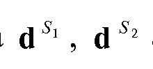
- the seismic data vector d is acquired due to the near- simultaneous firing of two seismic sources called "Si" and "S 2 .”
- the seismic sources Si and S 2 are fired pursuant to a timing sequence, which may be based on a predetermined timing pattern or may be based on random or pseudo-random time delays. Regardless of the particular timing scheme, it is assumed for this example that the seismic source Si is fired before the seismic source S 2 for relevant traces, and it is further assumed that the zero times of the traces correspond to the firing times for Si (Sl-time).
- the zero times of the traces are in “Si time.”
- the offsets, or vectors, to the seismic sources Si and S 2 are called “x 1 " and “x 2 ,” respectively.
- the timing delays, denoted by “t” for the seismic source S 2 are known for each trace.
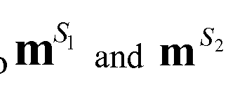
- the recorded energy for the seismic source Si may be modeled by applying a linear operator called "Li” (which represents the physics of the seismic source Si, the wave propagation associated with the source Si and the survey geometry associated with the seismic source Si) to an unknown model called "mi", which describes the geology that affects the energy that propagates from the seismic source Si.
- the model mi contains one element for each parameter in the model space.
- the model space may be parameterized by slowness or by its square, corresponding to linear or hyperbolic/parabolic Radon transforms, respectively.
- the linear operator Li is a function of the offsets to the source Si, the parameters that characterize the model space, and time or frequency.
- a seismic data vector di contains one element for each trace (at each time or frequency) and is the component of the seismic data d, which is associated with the seismic source Si.
- the seismic data vector di represents the dataset attributable to the seismic source Si.
- the seismic data vector di may be described as follows:
- s can be 1 or 2, referring to source 1 or source 2; j and k are the j'th row and k'th column of linear operator L s ; C IS the j 'th offset to source s;
- P sk is the k'th slowness of source s; ⁇ is angular frequency; and i (in the exponent) is the square root of -1.
- the energy that is associated with the seismic source S 2 appears incoherent in the seismic data vector d.
- the energy is related to a coherent dataset in which the firing times for the seismic source S 2 are at time zero (i.e., seismic source S 2 time) by the application of time shifts t; to the traces.
- a diagonal linear operator called “D 2 " may be used for purposes of describing these time shifts, such that the component of the seismic data vector d, which is associated with the seismic source S 2 and which is called "d 2 M may be described as follows:
- s is 2 referring source 2; j and k are the j'th row and k'th column of linear operator L s ;
- $ j is the j'th offset to source s; the k'th slowness of source s; ⁇ is angular frequency; and i (in the exponent) is the square root of -1; all of which are similar to L l s and where is the Kronecker delta
- a linear operator called “L2” represents the physics of the seismic source S 2 , the wave propagation associated with the seismic source S 2 and the survey geometry associated with the seismic source S 2 .
- a model called “m 2 " describes the geology that affects the energy that propagates from the seismic source S 2 .
- the composite seismic energy signal that is recorded by the seismic sensors is attributable to both seismic sources Si and S 2 .
- the seismic data vector d i.e., the recorded data
- the seismic data vectors di and d 2 are a combination of the seismic data vectors di and d 2 , as described below:
- the seismic data vector d may be represented as the following linear system:
- Eq. 4 may be solved (i.e., jointly inverted) for the model vector m (i.e., (mi; m 2 )) using standard techniques, such as the least squares algorithm; after the model vector m is known, Eqs. 1 and 2 may be applied with the models mi and m 2 for purposes of separating the seismic data vector d into the seismic data vectors di and d 2 , i.e., into the datasets that indicate the measurements attributable to each seismic source.
- the simultaneous sources are source 1 and source 2 etc. There may be more than two sources, but for simplicity, only two sources are discussed. It is straightforward to include more than two sources.
- the linear operator Li for source 1 and D 2 L 2 for source 2 may be represented by their basis functions, b, as in Eq. 5, below.
- the position vector can be the offset to the source location; are 2L+l frequencies;
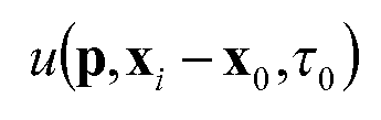
- T 0 is the intercept time which represents the arrival time at position x 0 of an event or seismic wavefront with slowness p; and is called the phase function, which is a function of slowness p, the relative
- frequencies and positions are spread around a central frequency or position.
- the actual frequencies or positions do not need to be arranged in a symmetric fashion. Any arrangement is acceptable for the methods described here.
- phase function may be a linear function, a hyperbolic
- phase function or another type of function, depending on the event refiected by subsurface structure.
- the phase function is assumed to be a linear function, which is a good first order approximation. If an event is linear, the phase function may be expressed as:
- phase function may be written as:
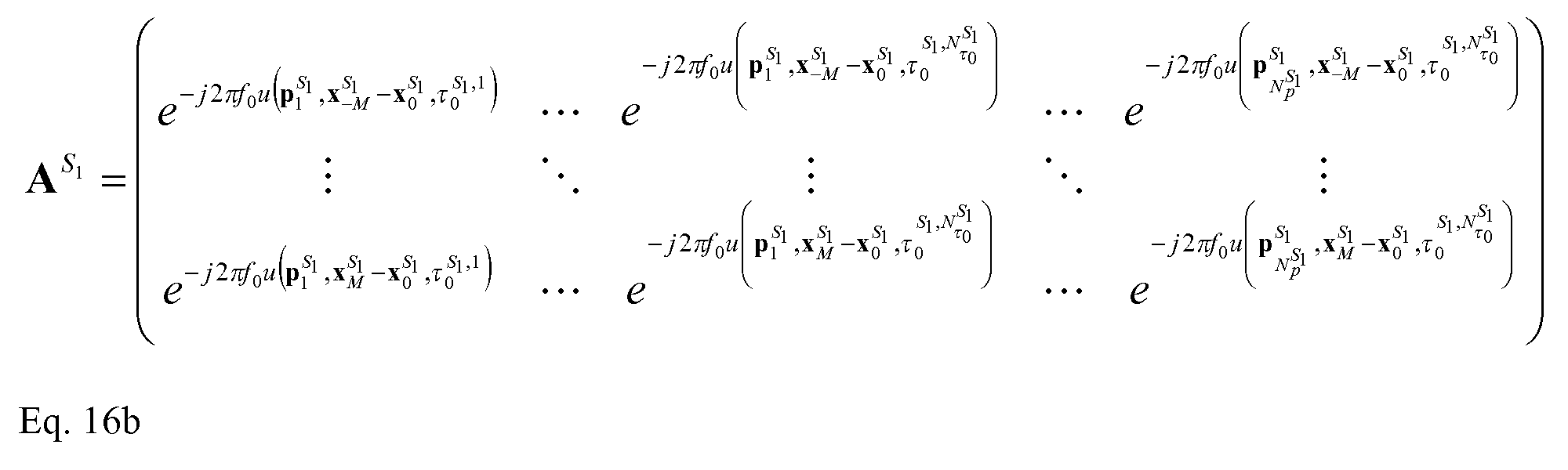
- the frequency-diverse array response or steering vector at slowness, p, and frequency, fo for modeling the coherent source (Si) can be written as in Eq. 8.
- the random delay time of S 2 the random delay time of S 2 .
- Equation 9 modeling the incoherent source (S 2 ) can be written as in Equation 9, below.
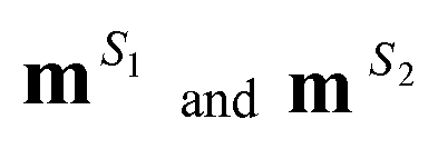
- the recorded data, d can be modeled by using a set of basis functions for the coherent source (Si) defined as Eq. 8 with different slownesses and different arrival times at sensor, x 0 , for each slowness, and another set of basis functions for the incoherent source (S 2 ), defined as Eq. 9 with different slownesses and different arrival times at sensor x 0 for each slowness.
- the linear operator matrix A may be constructed as shown in Eq. 14: where are defined in Eq. 8 and Eq. 9, respectively.
- the data separation problem may be converted to an optimization problem, e.g. a one-norm or zero-norm optimization problem, similar to that as in '402 application, as written in Eq. 4. More specifically, the decomposition problem may be written as
- the basis functions are expanded to include multiple frequencies. This is equivalent to filtering the central frequency fo by using the frequencies around the central frequency, hence the phrase "frequency diverse" in referring to this method.
- the model space may include multiple slownesses between the maximum and minimum slowness P max to P min an d multiple times between a range of intercept time maximum
- the model space m is related to both slowness p and intercept time ⁇ 0 at the reference trace x 0 .
- the multiple intercept time ⁇ 0 included is used to correct the phases of the multiple frequencies in the basis function as defined in Eq. 5.
- this method can process data regardless whether the data are aliased or not. This property makes this method very useful for aliased data, because most other separation methods have difficulties in separating data if the data are aliased as a result of spatial sampling limitations.
- the phase function may be selectable based on the targeted events reflected from the subsurface structures. More appropriate phase functions, e.g. linear or hyperbolic, may be used to closely conform to the event curvature to avoid data loss during the data separation process, e.g. for events from high-dip structures.
- phase functions e.g. linear or hyperbolic
- the one-norm or zero-norm optimization problem is constructed for each frequency (also referred to as reference frequency fo) in the acquired composite data. Once the data in one frequency are separated, the data with another frequency are selected. The central frequency (or the reference frequency) is shifted and the process repeated until relevant frequencies in the dataset are filtered. Separated frequency-space data at relevant frequencies may be combined, and then transformed back to the time-space domain to form the separated data in the time-space domain.
- basis functions are localized in time and frequency or in time, frequency and space. There is no assumption on source signatures. In general, it is not equivalent to applying a band-pass filter or source signature to the time domain Radon transform, because the sidelobes of the filter or mismatch of the source signature may make the model less sparse.
- the simultaneous source separation method 200 may proceed as follows: • sort the composite data into a gather where one of the sources appears to be coherent and the other to be incoherent (210);
- the separated data from the method 200 are dataset 1 , due to source 1 at source 1 time (Sl), and dataset 2, due to source 2 at source 1 time (Sl).
- Dataset 1 is in its native time, i.e. dataset 1 is coherent. It may be useful to realign the dataset 2 to source 2 time (S2) such that the dataset 2 is coherent as well.
- This method 200 converts a data separation problem for simultaneous sources into a standard one-norm or zero-norm optimization problem.
- the one-norm or zero-norm optimization problem is well known, well researched, and well developed. There are many efficient and cost effective algorithms that can be used.
- the cost of the method 200 is mainly the cost of solving the one-norm or zero-norm optimization problem in (260) described above.
- the method 200 is used to separate data from two sources.
- the method 200 can be extended readily to more than two sources by simply making the matrix A and model m contain more basis functions corresponding to additional sources.
- the model vector m and the operator matrix A may have greater dimensions.
- the dataset due to other sources may also need to be re-aligned to their native source times to make the dataset coherent.
- the method of separation is identical, whether there are two sources or more.
- Figures 3a-3h illustrate an example of a synthetic dataset used to test a separation method described above.
- the combined recorded data (pcsl) as in Figure 3a for the separation process were created by adding two synthetic aliasing linear events corresponding to each of the two sources (plsl and p2sl).
- the source interval of the synthetic data is 75 m and the frequency range is 3-80 Hz.
- the f-k spectra of the composite data (fk-pcsl) are illustrated in Figure 3b.
- the source 1 data in time-space domain (plsl) and its corresponding data in frequency-wavenumber domain in Si -time (fk-plsl) are shown in Figures 3c and 3d respectively.
- the source 2 data in time-space domain (p2s2) and its corresponding data in frequency-wavenumber domain in S2-time (fk-p2s2) are shown in Figures 3g and 3h respectively.
- S2 time the data recorded from source S2 are coherent.
- the source 2 data, in time-space domain (p2sl) but in SI time, and its corresponding data in frequency-wavenumber domain in Sl-time (fk-p2sl), are shown in Figures 3e and 3f respectively.
- 3e and 3f due to the timing that is aligned to SI time, the shooting time of source 2 at each trace has a time delay which appears to be random. It may be seen in the frequency-wavenumber domain, as in Figures 3b, 3d and 3h that the two linear events in source 1 and source 2 are aliasing.
- Figures 5 a - 5d illustrate another example with an actual acquired seismic marine dataset.
- Figure 5a shows the raw data in si time.
- the shot interval in this example dataset is 75 m.
- the amplitude varies greatly because of the complex geological structure.
- Figure 5b shows the separated source 1 in SI -time
- Figure 5 c shows the separated source 2 in Si -time
- Figure 5d shows the separated source 2 in S2-time.
- the separated datasets Figures 5b and 5d at their respectively times show wavefields from subsurface structures.
- FIG. 6 Portions of methods described above may be implemented in a computer system 600, one of which is shown in Figure 6.
- the system computer 630 may be in communication with disk storage devices 629, 631, 633 and 635, which may be external hard disk storage devices and measurement sensors (not shown). It is contemplated that disk storage devices 629, 631, 633 and 635 are conventional hard disk drives, and as such, may be implemented by way of a local area network or by remote access. While disk storage devices are illustrated as separate devices, a single disk storage device may be used to store any and all of the program instructions, measurement data, and results as desired.
- real-time data from the sensors may be stored in disk storage device 631.
- Various non-real-time data from different sources may be stored in disk storage device 633.
- the system computer 630 may retrieve the appropriate data from the disk storage devices 631 or 633 to process data according to program instructions that correspond to implementations of various techniques described herein.
- the program instructions may be written in a computer programming language, such as C++, Java and the like.
- the program instructions may be stored in a computer-readable medium, such as program disk storage device 635.
- Such computer-readable media may include computer storage media.
- Computer storage media may include volatile and non- volatile media, and removable and non-removable media implemented in any method or technology for storage of information, such as computer-readable instructions, data structures, program modules or other data.
- Computer storage media may further include RAM, ROM, erasable programmable read-only memory (EPROM), electrically erasable programmable read-only memory (EEPROM), flash memory or other solid state memory technology, CD-ROM, digital versatile disks (DVD), or other optical storage, magnetic cassettes, magnetic tape, magnetic disk storage or other magnetic storage devices, or any other medium which can be used to store the desired information and which can be accessed by the system computer 630. Combinations of any of the above may also be included within the scope of computer readable media.
- the system computer 630 may present output primarily onto graphics display 627, or via printer 628 (not shown).
- the system computer 630 may store the results of the methods described above on disk storage 629, for later use and further analysis.
- the keyboard 626 and the pointing device (e.g., a mouse, trackball, or the like) 625 may be provided with the system computer 630 to enable interactive operation.
- the system computer 630 may be located on-site, e.g. as part of processing unit 23 on-board a vessel 20 as in Figure 1 or at a data center remote from the field.
- the system computer 630 may be in communication with equipment on site to receive data of various measurements.
- Such data after conventional formatting and other initial processing, may be stored by the system computer 630 as digital data in the disk storage 631 or 633 for subsequent retrieval and processing in the manner described above.
- Figure 6 illustrates the disk storage, e.g. 631 as directly connected to the system computer 630, it is also contemplated that the disk storage device may be accessible through a local area network or by remote access.
- disk storage devices 629, 631 are illustrated as separate devices for storing input data and analysis results, the disk storage devices 629, 631 may be implemented within a single disk drive (either together with or separately from program disk storage device 633), or in any other conventional manner as will be fully understood by one of skill in the art having reference to this specification.
Landscapes
- Life Sciences & Earth Sciences (AREA)
- Physics & Mathematics (AREA)
- Remote Sensing (AREA)
- Engineering & Computer Science (AREA)
- Geology (AREA)
- Environmental & Geological Engineering (AREA)
- Acoustics & Sound (AREA)
- General Life Sciences & Earth Sciences (AREA)
- General Physics & Mathematics (AREA)
- Geophysics (AREA)
- Oceanography (AREA)
- Geophysics And Detection Of Objects (AREA)
- Image Processing (AREA)
Abstract
Description


















Claims




Priority Applications (6)
| Application Number | Priority Date | Filing Date | Title |
|---|---|---|---|
| EP12854310.5A EP2786176B1 (en) | 2011-11-28 | 2012-11-27 | Separation of simultaneous source data |
| AU2012345565A AU2012345565B2 (en) | 2011-11-28 | 2012-11-27 | Separation of simultaneous source data |
| BR112014012550A BR112014012550A2 (en) | 2011-11-28 | 2012-11-27 | A method for separating composite data from simultaneous sources containing data responses to at least two sources, apparatus for acquiring and separating simultaneous source data by a diverse frequency filter, where composite simultaneous source data contains responses to at least two sources, and system data processing to separate simultaneous source composite data by diverse frequency filtering, where simultaneous source composite data contains responses to at least two sources |
| CA2856335A CA2856335A1 (en) | 2011-11-28 | 2012-11-27 | Separation of simultaneous source data |
| MX2014005898A MX2014005898A (en) | 2011-11-28 | 2012-11-27 | Separation of simultaneous source data. |
| RU2014126340A RU2014126340A (en) | 2011-11-28 | 2012-11-27 | SEPARATING DATA FROM SIMULTANEOUS SOURCES |
Applications Claiming Priority (2)
| Application Number | Priority Date | Filing Date | Title |
|---|---|---|---|
| US13/305,234 | 2011-11-28 | ||
| US13/305,234 US9091787B2 (en) | 2011-11-28 | 2011-11-28 | Separation of simultaneous source data |
Publications (1)
| Publication Number | Publication Date |
|---|---|
| WO2013080128A1 true WO2013080128A1 (en) | 2013-06-06 |
Family
ID=48466791
Family Applications (1)
| Application Number | Title | Priority Date | Filing Date |
|---|---|---|---|
| PCT/IB2012/056768 Ceased WO2013080128A1 (en) | 2011-11-28 | 2012-11-27 | Separation of simultaneous source data |
Country Status (8)
| Country | Link |
|---|---|
| US (1) | US9091787B2 (en) |
| EP (1) | EP2786176B1 (en) |
| AU (1) | AU2012345565B2 (en) |
| BR (1) | BR112014012550A2 (en) |
| CA (1) | CA2856335A1 (en) |
| MX (1) | MX2014005898A (en) |
| RU (1) | RU2014126340A (en) |
| WO (1) | WO2013080128A1 (en) |
Cited By (3)
| Publication number | Priority date | Publication date | Assignee | Title |
|---|---|---|---|---|
| US9618636B2 (en) | 2013-03-15 | 2017-04-11 | Westerngeco L.L.C. | Seismic acquisition using phase-shifted sweeps |
| US10557955B2 (en) | 2014-03-20 | 2020-02-11 | Westerngeco L.L.C. | Reconstructing impulsive source seismic data from time distributed firing airgun array data |
| US11385372B2 (en) | 2015-12-22 | 2022-07-12 | Shell Usa, Inc. | Method and system for generating a seismic gather |
Families Citing this family (19)
| Publication number | Priority date | Publication date | Assignee | Title |
|---|---|---|---|---|
| US9075159B2 (en) * | 2011-06-08 | 2015-07-07 | Chevron U.S.A., Inc. | System and method for seismic data inversion |
| US9103943B2 (en) * | 2011-11-28 | 2015-08-11 | Fugro-Geoteam As | Acquisition and processing of multi-source broadband marine seismic data |
| US20150066374A1 (en) * | 2012-04-04 | 2015-03-05 | Westerngeco L.L.C. | Seismic data processing with frequency diverse de-aliasing filtering |
| WO2015168130A1 (en) * | 2014-04-28 | 2015-11-05 | Westerngeco Llc | Wavefield reconstruction |
| US9851463B2 (en) | 2014-07-01 | 2017-12-26 | Pgs Geophysical As | Interference attenuation of a residual portion of seismic data |
| US10094944B2 (en) | 2014-09-05 | 2018-10-09 | Westerngeco L.L.C. | Separating survey data for a plurality of survey sources |
| US10928535B2 (en) | 2015-05-01 | 2021-02-23 | Reflection Marine Norge As | Marine vibrator directive source survey |
| WO2016179206A1 (en) | 2015-05-05 | 2016-11-10 | Schlumberger Technology Corporation | Removal of acquisition effects from marine seismic data |
| WO2017096081A1 (en) | 2015-12-02 | 2017-06-08 | Westerngeco Llc | Land seismic sensor spread with adjacent multicomponent seismic sensor pairs on average at least twenty meters apart |
| US11143774B2 (en) | 2015-12-22 | 2021-10-12 | Shell Oil Company | Method and system for separating blended seismic data |
| GB2547940A (en) * | 2016-03-04 | 2017-09-06 | Robertsson Johan | Source separation method |
| GB2553257A (en) * | 2016-03-28 | 2018-03-07 | Seismic Apparition Gmbh | De-aliased source separation method |
| GB2550181A (en) * | 2016-05-12 | 2017-11-15 | Seismic Apparition Gmbh | Simultaneous source acquisition and separation on general related sampling grids |
| US20170363756A1 (en) | 2016-06-15 | 2017-12-21 | Schlumerger Technology Corporation | Systems and methods for acquiring seismic data with gradient data |
| GB2555820B (en) | 2016-11-10 | 2021-10-27 | Apparition Geoservices Gmbh | Simultaneous source acquisition and separation method |
| GB2558630A (en) * | 2017-01-12 | 2018-07-18 | Seismic Apparition Gmbh | Method for dealiasing data |
| GB2560991B (en) | 2017-03-31 | 2021-12-29 | Apparition Geoservices Gmbh | Method for seismic acquisition and processing |
| US10871586B2 (en) | 2017-05-17 | 2020-12-22 | Cgg Services Sas | Device and method for multi-shot wavefield reconstruction |
| AU2020405157A1 (en) | 2019-12-20 | 2022-05-26 | Dug Technology (Australia) Pty Ltd. | Deconvolution of down-going seismic wavefields |
Citations (6)
| Publication number | Priority date | Publication date | Assignee | Title |
|---|---|---|---|---|
| US5764516A (en) | 1995-12-29 | 1998-06-09 | Atlantic Richfield Company | Method and system for surface-consistent phase and time lag correction of seismic data |
| EP0884608B1 (en) * | 1997-06-09 | 2008-12-31 | Westerngeco Seismic Holdings Limited | Seismic surveying |
| US20100039894A1 (en) * | 2008-08-15 | 2010-02-18 | Abma Raymond L | Method for separating independent simultaneous sources |
| US20100182873A1 (en) * | 2009-01-20 | 2010-07-22 | Tilman Kluver | Method for wavefield separation for dual-sensor data using kirchhoff-type datuming and migration |
| US20100271904A1 (en) * | 2009-04-24 | 2010-10-28 | Ian Moore | Separating seismic signals produced by interfering seismic sources |
| US20110141848A1 (en) * | 2008-07-16 | 2011-06-16 | Beasley Craig J | Optimizing a Seismic Survey for Source Separation |
Family Cites Families (6)
| Publication number | Priority date | Publication date | Assignee | Title |
|---|---|---|---|---|
| US5986973A (en) * | 1997-09-04 | 1999-11-16 | Western Atlas International, Inc. | Energy minimization in surface multiple attenuation |
| US7599798B2 (en) * | 2006-09-11 | 2009-10-06 | Westerngeco L.L.C. | Migrating composite seismic response data to produce a representation of a seismic volume |
| US8248886B2 (en) * | 2007-04-10 | 2012-08-21 | Exxonmobil Upstream Research Company | Separation and noise removal for multiple vibratory source seismic data |
| US20090168600A1 (en) | 2007-12-26 | 2009-07-02 | Ian Moore | Separating seismic signals produced by interfering seismic sources |
| US8902697B2 (en) | 2008-10-22 | 2014-12-02 | Westerngeco L.L.C. | Removing seismic interference using simultaneous or near simultaneous source separation |
| WO2010080366A1 (en) * | 2009-01-09 | 2010-07-15 | Exxonmobil Upstream Research Company | Hydrocarbon detection with passive seismic data |
-
2011
- 2011-11-28 US US13/305,234 patent/US9091787B2/en not_active Expired - Fee Related
-
2012
- 2012-11-27 BR BR112014012550A patent/BR112014012550A2/en not_active IP Right Cessation
- 2012-11-27 RU RU2014126340A patent/RU2014126340A/en not_active Application Discontinuation
- 2012-11-27 CA CA2856335A patent/CA2856335A1/en not_active Abandoned
- 2012-11-27 WO PCT/IB2012/056768 patent/WO2013080128A1/en not_active Ceased
- 2012-11-27 AU AU2012345565A patent/AU2012345565B2/en not_active Ceased
- 2012-11-27 EP EP12854310.5A patent/EP2786176B1/en not_active Not-in-force
- 2012-11-27 MX MX2014005898A patent/MX2014005898A/en active IP Right Grant
Patent Citations (6)
| Publication number | Priority date | Publication date | Assignee | Title |
|---|---|---|---|---|
| US5764516A (en) | 1995-12-29 | 1998-06-09 | Atlantic Richfield Company | Method and system for surface-consistent phase and time lag correction of seismic data |
| EP0884608B1 (en) * | 1997-06-09 | 2008-12-31 | Westerngeco Seismic Holdings Limited | Seismic surveying |
| US20110141848A1 (en) * | 2008-07-16 | 2011-06-16 | Beasley Craig J | Optimizing a Seismic Survey for Source Separation |
| US20100039894A1 (en) * | 2008-08-15 | 2010-02-18 | Abma Raymond L | Method for separating independent simultaneous sources |
| US20100182873A1 (en) * | 2009-01-20 | 2010-07-22 | Tilman Kluver | Method for wavefield separation for dual-sensor data using kirchhoff-type datuming and migration |
| US20100271904A1 (en) * | 2009-04-24 | 2010-10-28 | Ian Moore | Separating seismic signals produced by interfering seismic sources |
Non-Patent Citations (1)
| Title |
|---|
| See also references of EP2786176A4 * |
Cited By (4)
| Publication number | Priority date | Publication date | Assignee | Title |
|---|---|---|---|---|
| US9618636B2 (en) | 2013-03-15 | 2017-04-11 | Westerngeco L.L.C. | Seismic acquisition using phase-shifted sweeps |
| US10345461B2 (en) | 2013-03-15 | 2019-07-09 | Westerngeco L.L.C. | Seismic data apparition from phase shifted sources |
| US10557955B2 (en) | 2014-03-20 | 2020-02-11 | Westerngeco L.L.C. | Reconstructing impulsive source seismic data from time distributed firing airgun array data |
| US11385372B2 (en) | 2015-12-22 | 2022-07-12 | Shell Usa, Inc. | Method and system for generating a seismic gather |
Also Published As
| Publication number | Publication date |
|---|---|
| RU2014126340A (en) | 2016-01-27 |
| MX2014005898A (en) | 2014-06-19 |
| US20130135965A1 (en) | 2013-05-30 |
| BR112014012550A2 (en) | 2017-06-13 |
| EP2786176A4 (en) | 2015-11-25 |
| CA2856335A1 (en) | 2013-06-06 |
| US9091787B2 (en) | 2015-07-28 |
| AU2012345565A1 (en) | 2014-05-22 |
| EP2786176B1 (en) | 2016-12-21 |
| EP2786176A1 (en) | 2014-10-08 |
| AU2012345565B2 (en) | 2015-12-10 |
Similar Documents
| Publication | Publication Date | Title |
|---|---|---|
| US9091787B2 (en) | Separation of simultaneous source data | |
| EP2422221B1 (en) | Separating seismic signals produced by interfering seismic sources | |
| US8339896B2 (en) | Method for separating seismic sources in marine seismic surveys | |
| CN101556339B (en) | Method for deghosting marine seismic streamer data with irregular receiver positions | |
| US9541659B2 (en) | Noise removal from 3D seismic representation | |
| CN110770608B (en) | Compressive sensing imaging | |
| EP2375268B1 (en) | Method for separating up and down propagating pressure and vertical velocity fields from pressure and three-axial motion sensors in towed streamers | |
| CA2648682C (en) | Method for wavefield separation in 3d dual sensor towed streamer data with aliased energy in cross-streamer direction | |
| US20090168600A1 (en) | Separating seismic signals produced by interfering seismic sources | |
| EP2491430A2 (en) | Methods to process seismic data contaminated by coherent energy radiated from more than one source | |
| EP2180345A1 (en) | Removing seismic interference using simultaneous or near simultaneous source separation | |
| US10996359B2 (en) | Removal of acquisition effects from marine seismic data | |
| CA2801531A1 (en) | Method and system for determining source signatures after source ghost removal | |
| US20150066374A1 (en) | Seismic data processing with frequency diverse de-aliasing filtering |
Legal Events
| Date | Code | Title | Description |
|---|---|---|---|
| 121 | Ep: the epo has been informed by wipo that ep was designated in this application |
Ref document number: 12854310 Country of ref document: EP Kind code of ref document: A1 |
|
| REEP | Request for entry into the european phase |
Ref document number: 2012854310 Country of ref document: EP |
|
| WWE | Wipo information: entry into national phase |
Ref document number: 2012854310 Country of ref document: EP |
|
| WWE | Wipo information: entry into national phase |
Ref document number: MX/A/2014/005898 Country of ref document: MX |
|
| ENP | Entry into the national phase |
Ref document number: 2856335 Country of ref document: CA |
|
| ENP | Entry into the national phase |
Ref document number: 2012345565 Country of ref document: AU Date of ref document: 20121127 Kind code of ref document: A |
|
| NENP | Non-entry into the national phase |
Ref country code: DE |
|
| ENP | Entry into the national phase |
Ref document number: 2014126340 Country of ref document: RU Kind code of ref document: A |
|
| REG | Reference to national code |
Ref country code: BR Ref legal event code: B01A Ref document number: 112014012550 Country of ref document: BR |
|
| ENP | Entry into the national phase |
Ref document number: 112014012550 Country of ref document: BR Kind code of ref document: A2 Effective date: 20140523 |