WO2013080340A1 - 車体構造 - Google Patents
車体構造 Download PDFInfo
- Publication number
- WO2013080340A1 WO2013080340A1 PCT/JP2011/077704 JP2011077704W WO2013080340A1 WO 2013080340 A1 WO2013080340 A1 WO 2013080340A1 JP 2011077704 W JP2011077704 W JP 2011077704W WO 2013080340 A1 WO2013080340 A1 WO 2013080340A1
- Authority
- WO
- WIPO (PCT)
- Prior art keywords
- wall
- floor
- width direction
- vehicle width
- vehicle body
- Prior art date
- Legal status (The legal status is an assumption and is not a legal conclusion. Google has not performed a legal analysis and makes no representation as to the accuracy of the status listed.)
- Ceased
Links
Images


Classifications
-
- B—PERFORMING OPERATIONS; TRANSPORTING
- B62—LAND VEHICLES FOR TRAVELLING OTHERWISE THAN ON RAILS
- B62D—MOTOR VEHICLES; TRAILERS
- B62D27/00—Connections between superstructure or understructure sub-units
- B62D27/02—Connections between superstructure or understructure sub-units rigid
- B62D27/023—Assembly of structural joints
-
- B—PERFORMING OPERATIONS; TRANSPORTING
- B62—LAND VEHICLES FOR TRAVELLING OTHERWISE THAN ON RAILS
- B62D—MOTOR VEHICLES; TRAILERS
- B62D25/00—Superstructure or monocoque structure sub-units; Parts or details thereof not otherwise provided for
- B62D25/20—Floors or bottom sub-units
- B62D25/2009—Floors or bottom sub-units in connection with other superstructure subunits
- B62D25/2036—Floors or bottom sub-units in connection with other superstructure subunits the subunits being side panels, sills or pillars
-
- B—PERFORMING OPERATIONS; TRANSPORTING
- B62—LAND VEHICLES FOR TRAVELLING OTHERWISE THAN ON RAILS
- B62D—MOTOR VEHICLES; TRAILERS
- B62D21/00—Understructures, i.e. chassis frame on which a vehicle body may be mounted
- B62D21/15—Understructures, i.e. chassis frame on which a vehicle body may be mounted having impact absorbing means, e.g. a frame designed to permanently or temporarily change shape or dimension upon impact with another body
- B62D21/157—Understructures, i.e. chassis frame on which a vehicle body may be mounted having impact absorbing means, e.g. a frame designed to permanently or temporarily change shape or dimension upon impact with another body for side impacts
-
- B—PERFORMING OPERATIONS; TRANSPORTING
- B62—LAND VEHICLES FOR TRAVELLING OTHERWISE THAN ON RAILS
- B62D—MOTOR VEHICLES; TRAILERS
- B62D27/00—Connections between superstructure or understructure sub-units
- B62D27/06—Connections between superstructure or understructure sub-units readily releasable
-
- B—PERFORMING OPERATIONS; TRANSPORTING
- B62—LAND VEHICLES FOR TRAVELLING OTHERWISE THAN ON RAILS
- B62D—MOTOR VEHICLES; TRAILERS
- B62D29/00—Superstructures, understructures, or sub-units thereof, characterised by the material thereof
- B62D29/04—Superstructures, understructures, or sub-units thereof, characterised by the material thereof predominantly of synthetic material
- B62D29/043—Superstructures
-
- B—PERFORMING OPERATIONS; TRANSPORTING
- B62—LAND VEHICLES FOR TRAVELLING OTHERWISE THAN ON RAILS
- B62D—MOTOR VEHICLES; TRAILERS
- B62D29/00—Superstructures, understructures, or sub-units thereof, characterised by the material thereof
- B62D29/04—Superstructures, understructures, or sub-units thereof, characterised by the material thereof predominantly of synthetic material
- B62D29/048—Connections therefor, e.g. joints
Definitions
- the vehicle body structure according to the third aspect of the present invention is the vehicle body structure according to the first or second aspect, and is stretched between the pillar and the floor outside the connecting member in the vehicle width direction. A tension member.
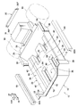
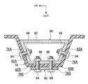
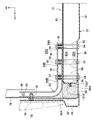
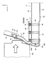
- FIG. 5 is a sectional view taken along line XX in FIG. 4. It is a perspective view which shows the connection member which concerns on this embodiment. It is side sectional drawing which shows the vehicle body structure which concerns on this embodiment before a side collision. It is side sectional drawing which shows the vehicle body structure which concerns on this embodiment after a side collision. It is side sectional drawing which shows the vehicle body structure which concerns on this embodiment after a side collision.
- an arrow FR appropriately shown in the drawing indicates a forward direction in the vehicle longitudinal direction
- an arrow UP indicates an upward direction in the vehicle vertical direction
- an arrow OUT indicates an outside in the vehicle width direction.
- the front-rear direction and the up-down direction when using the front-rear direction and the up-down direction unless otherwise specified, the front-rear direction of the vehicle body and the vertical direction of the vehicle body are indicated.
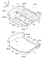
- the floor portion 22 has a flat lower wall 32 substantially along a horizontal plane.
- An outer wall 34 is erected upward from both sides of the lower wall 32 in the vehicle width direction.
- a pair of left and right rockers 36 and a center skeleton forming portion 38 are provided on the upper side of the vehicle body of the lower wall 32 as a skeleton structure in which the longitudinal direction is the longitudinal direction.
- the left and right rockers 36 include a lower wall 32, an upper wall 40 that faces the lower wall 32 in the vertical direction, an outer wall 34, and an inner wall 42 that faces the outer wall 34 in the vehicle width direction. It has a frame-like closed cross-sectional structure.
- the center skeleton forming portion 38 is configured as a rectangular frame-like closed cross-sectional structure in a front cross-sectional view by a lower wall 32, an upper wall 44 facing the lower wall 32 in the vertical direction, and a pair of center side walls 46 facing each other. ing.
- the inclined wall 50S is inclined with respect to the front / rear (horizontal) direction so that the rear end side is located below the front end side, and the front upper end thereof is the lower end of the upper / lower wall 50V substantially along the vertical direction of the rear wall 50. It is continuous.
- the vertical position of the front upper end (boundary portion with the vertical wall 50V) of the inclined wall 50S is substantially the vertical position of the center line CL (line passing through the centroid) CL of the front EA member 16 in a side view. Have been matched.
- the rear lower end of the inclined wall 50 ⁇ / b> S is continuous with the upper walls 40 and 44 facing the lower wall 32 in the formation portion of the rocker 36 and the center skeleton forming portion 38 in the floor portion 22. Further, the rear lower end of the inclined wall 50 ⁇ / b> S is continuous with an upper flange 12 ⁇ / b> UF (described later) joined to the lower wall 32 in a portion where the rocker 36 and the center skeleton forming portion 38 are not formed in the floor portion 22.
- the lower back portion 26 includes a rear wall 54 and a front wall 56 that are opposed to each other in the front-rear direction, and an upper wall 58 that is opposed to the lower wall 32. That is, the lower back portion 26 is configured by the lower wall 32, the rear wall 54, the front wall 56, and the upper wall 58 in a closed cross-sectional structure in a side sectional view.
- the front wall 56 is inclined with respect to the front-rear (horizontal) direction as a whole so that the front end side is positioned below the rear end side.
- the upper panel 12U includes an upper wall 40 and an inner wall 42 (skeleton forming portion) of the rocker 36, an upper wall 44 and a pair of center side walls 46 (skeleton forming portion) of the center skeleton forming portion 38, and a dash lower portion 24.
- Rear wall 50 (upper and lower walls 50V, inclined wall 50S) and upper wall 52, front wall 56 and upper wall 58 of lower back portion 26, upper wall 62, front wall 64 and rear wall 66 of center cross portion 60, It includes an inner wall 28B of the front side wall 28, an inner wall 30B of the rear side wall 30, and an upper flange 12UF projecting outward from the peripheral edge portion in plan view.
- the upper flange 12UF includes an inner side wall 42, a center side wall 46, an inclined wall 50S (a rocker 36, a non-formation part of the center skeleton formation part 38), and a front wall 56 (a rocker 36, a non-formation part of the center skeleton formation part 38). Further, it is also formed at each lower end of the front wall 64 and the rear wall 66.
- the front suspension module 14 includes at least a suspension member 70 and a pair of left and right front suspensions (not shown).
- the suspension member 70 has a closed cross-sectional structure as seen in a side cross-sectional view of FIG.
- the rear suspension module 18 includes at least a suspension member 74 and a pair of left and right rear suspensions (not shown).
- the left and right rear suspensions are assembled as a whole to the suspension member 74, and the suspension member 74 is configured to rotatably support the rear wheel Wr via each rear suspension. That is, each rear suspension is supported by the suspension member 74 so as to function independently without depending on other parts constituting the vehicle body of the automobile V.
- the rear suspension member 74 is fixed to the lower back portion 26 by fastening. Specifically, the suspension member 74 is fastened and fixed via a connection plate 72 to an inclined wall 54A that is integrally formed on the rear wall 54 of the lower back portion 26 so as to protrude rearward of the vehicle body.
- the front EA member 16 has a box shape (substantially rectangular) having a length along the vehicle width direction substantially equal to the length of the suspension member 70 in the vehicle width direction (interval between the left and right front suspensions). It is formed in a box shape.
- the front EA member 16 is fastened and fixed to the suspension member 70 at a flange 16F protruding from its rear end.
- the side EA member 68 extends along the longitudinal direction of the vehicle body substantially equal to the length of the rocker 36 in the longitudinal direction of the vehicle body (the distance between the front side wall 28 and the rear side wall 30). It is formed in a box shape (substantially rectangular box shape) having a length.
- the side EA member 68 has slits 68A formed on its inner side in the vehicle width direction and extending in the front-rear direction at a substantially central portion in the vertical direction.
- the slits 68A are formed in the upper flange 12UF and the lower flange 12LF in the rocker 36. They are fixed to the rocker 36 by being bonded so as to sandwich them from above and below.
- the center pillar 78 in the automobile V is made of resin. That is, the center pillar 78 is formed of a fiber reinforced resin material containing reinforcing fibers such as carbon fibers, glass fibers, and aramid fibers.
- the front pillar and the rear pillar which are not shown in figure are also made from resin, in this embodiment, the center pillar 78 is demonstrated.
- the center pillar 78 is formed in a substantially hat shape with a cross section along the horizontal direction.
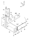
- the center pillar 78 is connected (joined) to the floor portion 22 of the underbody 12 by a connecting member 80.
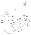
- the connecting member 80 is made of a highly ductile metal material such as aluminum or an alloy thereof, and is bent into a substantially “L” shape when viewed from the front as shown in FIGS. It is formed in a rectangular tube shape (closed cross-sectional shape) having a bent portion 80A.
- the connecting member 80 is further pressed inward in the vehicle width direction. Then, as shown in FIG. 9, since the collar member 76 is not fixed to the connecting member 80, the fragile portion 86 is broken by being pressed outward in the vehicle width direction relative to the bolt 94, and the connecting member 80.
- the floor fastening portion 84 slides (translates) inward in the vehicle width direction (until the bolt 94 is disposed in the through hole 84B).
Landscapes
- Engineering & Computer Science (AREA)
- Chemical & Material Sciences (AREA)
- Combustion & Propulsion (AREA)
- Transportation (AREA)
- Mechanical Engineering (AREA)
- Architecture (AREA)
- Structural Engineering (AREA)
- Body Structure For Vehicles (AREA)
Abstract
Description
樹脂製のアンダーボディ12は、平面視で略矩形状とされたフロア部22と、フロア部22の前端から上向きに立設されたダッシュロア部24と、フロア部22の後端から上向きに立設されたロアバック部26と、を含んで構成されている。ダッシュロア部24及びロアバック部26は、フロア部22の略全幅に亘る長さを有しており、正面視では車幅方向が長手方向とされた略矩形状に構成されている。
図1で示すように、フロントサスペンションモジュール14は、サスペンションメンバ70と、図示しない左右一対のフロントサスペンションとを少なくとも含んで構成されている。サスペンションメンバ70は、車幅方向が長手方向とされるとともに、図1の側断面視で閉断面構造とされている。
図1で示すように、フロントEA部材16は、サスペンションメンバ70の車幅方向の長さ(左右のフロントサスペンションの間隔)と略同等の車幅方向に沿った長さを有するボックス形状(略矩形箱状)に形成されている。そして、このフロントEA部材16は、その後端から張り出されたフランジ16Fにおいて、サスペンションメンバ70に締結固定されている。
図4で示すように、この自動車Vにおけるセンターピラー78は、樹脂製とされている。すなわち、このセンターピラー78は、例えば炭素繊維、ガラス繊維、アラミド繊維などの強化繊維を含有する繊維強化樹脂材料で成形されている。なお、図示しないフロントピラー及びリアピラーも樹脂製とされているが、本実施形態では、センターピラー78について説明する。
Claims (5)
- 車体下方側に配置された樹脂製のフロアと、
前記フロアの車幅方向外側で車体上下方向に延在するように配置された樹脂製のピラーと、
前記ピラー及び前記フロアよりも延性の高い材料で構成され、前記ピラーと前記フロアとを連結する連結部材と、
を有する車体構造。 - 前記連結部材は、金属材料で構成されている請求項1に記載の車体構造。
- 前記連結部材の車幅方向外側で、前記ピラーと前記フロアとの間に張設されたテンション部材を有する請求項1又は請求項2に記載の車体構造。
- 前記連結部材の下端部側は、車幅方向内側へ延在されて前記フロアにボルト締結されるフロア締結部とされており、
前記フロア締結部は、車幅方向外側から荷重が入力されて車幅方向内側へ押圧されたときに、ボルトによって破断される脆弱部を有する請求項1~請求項3の何れか1項に記載の車体構造。 - 前記脆弱部は、ボルト挿通孔と該ボルト挿通孔の車幅方向外側に形成された貫通孔との間とされている請求項4に記載の車体構造。
Priority Applications (5)
| Application Number | Priority Date | Filing Date | Title |
|---|---|---|---|
| PCT/JP2011/077704 WO2013080340A1 (ja) | 2011-11-30 | 2011-11-30 | 車体構造 |
| CN201180075105.8A CN103974875A (zh) | 2011-11-30 | 2011-11-30 | 车身结构 |
| EP11876598.1A EP2786918B1 (en) | 2011-11-30 | 2011-11-30 | Vehicle body structure |
| JP2013546907A JP5696793B2 (ja) | 2011-11-30 | 2011-11-30 | 車体構造 |
| US14/360,341 US9045164B2 (en) | 2011-11-30 | 2011-11-30 | Vehicle body structure |
Applications Claiming Priority (1)
| Application Number | Priority Date | Filing Date | Title |
|---|---|---|---|
| PCT/JP2011/077704 WO2013080340A1 (ja) | 2011-11-30 | 2011-11-30 | 車体構造 |
Publications (1)
| Publication Number | Publication Date |
|---|---|
| WO2013080340A1 true WO2013080340A1 (ja) | 2013-06-06 |
Family
ID=48534858
Family Applications (1)
| Application Number | Title | Priority Date | Filing Date |
|---|---|---|---|
| PCT/JP2011/077704 Ceased WO2013080340A1 (ja) | 2011-11-30 | 2011-11-30 | 車体構造 |
Country Status (5)
| Country | Link |
|---|---|
| US (1) | US9045164B2 (ja) |
| EP (1) | EP2786918B1 (ja) |
| JP (1) | JP5696793B2 (ja) |
| CN (1) | CN103974875A (ja) |
| WO (1) | WO2013080340A1 (ja) |
Cited By (7)
| Publication number | Priority date | Publication date | Assignee | Title |
|---|---|---|---|---|
| WO2015022389A1 (de) * | 2013-08-15 | 2015-02-19 | Bombardier Transportation Gmbh | Gehäuse zum aufnehmen von gegenständen |
| DE102014202799A1 (de) * | 2014-02-17 | 2015-08-20 | Bayerische Motoren Werke Aktiengesellschaft | Kraftfahrzeug mit B-Säulenfuß |
| JP2015182586A (ja) * | 2014-03-24 | 2015-10-22 | 本田技研工業株式会社 | 自動車の車体構造 |
| JP2015182587A (ja) * | 2014-03-24 | 2015-10-22 | 本田技研工業株式会社 | 自動車の車体構造 |
| WO2016031337A1 (ja) * | 2014-08-26 | 2016-03-03 | 本田技研工業株式会社 | 自動車車体および自動車車体の製造方法 |
| JP2018052390A (ja) * | 2016-09-30 | 2018-04-05 | マツダ株式会社 | フレーム部材 |
| JP2018052391A (ja) * | 2016-09-30 | 2018-04-05 | マツダ株式会社 | フレーム部材 |
Families Citing this family (14)
| Publication number | Priority date | Publication date | Assignee | Title |
|---|---|---|---|---|
| WO2012033000A1 (ja) * | 2010-09-06 | 2012-03-15 | 東レ株式会社 | 乗用車車室用構造体およびその製造方法 |
| IN2014DN07214A (ja) * | 2012-03-01 | 2015-04-24 | Toyota Motor Co Ltd | |
| CN104349971A (zh) * | 2012-06-08 | 2015-02-11 | 本田技研工业株式会社 | 汽车的frp制舱室 |
| DE102012021493A1 (de) * | 2012-10-31 | 2014-04-30 | Daimler Ag | Querträgeranordnung und Herstellungsverfahren |
| US9821852B2 (en) * | 2016-02-03 | 2017-11-21 | Ford Global Technologies Llc | Pressurized air insert for side impacts |
| US11077812B2 (en) | 2018-02-27 | 2021-08-03 | GM Global Technology Operations LLC | Composite energy-absorbing assembly |
| DE102018205826A1 (de) * | 2018-04-17 | 2019-10-17 | Röchling Automotive SE & Co. KG | Kfz-Karosserie mit Rohkarosse und Fahrzeugboden sowie einem Sicherungsstrukturbauteil |
| JP7063193B2 (ja) * | 2018-08-23 | 2022-05-09 | トヨタ自動車株式会社 | 車両前部構造 |
| DE102018215364B4 (de) * | 2018-09-11 | 2022-12-22 | Volkswagen Aktiengesellschaft | Karosseriestruktur für ein Fahrzeug |
| US10661840B1 (en) | 2018-11-28 | 2020-05-26 | GM Global Technology Operations LLC | Interlocking body and floor pan assembly for below floor energy stored vehicles |
| JP6950871B2 (ja) * | 2019-01-23 | 2021-10-13 | Jfeスチール株式会社 | 車体骨格部品 |
| JP7172669B2 (ja) | 2019-02-01 | 2022-11-16 | トヨタ自動車株式会社 | モノコック車両構造 |
| CN116946263B (zh) * | 2022-04-17 | 2026-06-09 | 北京车和家汽车科技有限公司 | 下车体框架总成和车辆 |
| JP7885699B2 (ja) * | 2023-01-31 | 2026-07-07 | トヨタ自動車株式会社 | ロッカ構造 |
Citations (6)
| Publication number | Priority date | Publication date | Assignee | Title |
|---|---|---|---|---|
| JP2007190992A (ja) * | 2006-01-18 | 2007-08-02 | Toyota Motor Corp | センタピラー下部構造 |
| JP2007237896A (ja) * | 2006-03-08 | 2007-09-20 | Toyota Auto Body Co Ltd | 自動車の車体下部構造 |
| JP2008213539A (ja) * | 2007-02-28 | 2008-09-18 | Honda Motor Co Ltd | 車体制振構造 |
| JP2008260334A (ja) * | 2007-04-10 | 2008-10-30 | Toyota Motor Corp | Frp製ボデー構造 |
| JP2008265416A (ja) * | 2007-04-17 | 2008-11-06 | Toyota Motor Corp | 車体構造 |
| JP2011088495A (ja) | 2009-10-20 | 2011-05-06 | Mazda Motor Corp | 車両の車体構造 |
Family Cites Families (11)
| Publication number | Priority date | Publication date | Assignee | Title |
|---|---|---|---|---|
| US5046778A (en) * | 1990-06-29 | 1991-09-10 | The Standard Products Company | Reduced weight vehicle door pillar |
| JPH05185960A (ja) * | 1992-01-10 | 1993-07-27 | Toyota Motor Corp | 車両の車体側部構造 |
| US6206458B1 (en) * | 1999-09-13 | 2001-03-27 | Daimlerchrysler Corporation | Vehicle body structure |
| DE10229401A1 (de) * | 2002-06-29 | 2004-01-22 | Dr.Ing.H.C. F. Porsche Ag | Aufbaustruktur für ein Fahrzeug, insbesondere einen Personenkraftwagen |
| DE10248661B4 (de) * | 2002-10-18 | 2004-11-25 | Daimlerchrysler Ag | Fahrgastzelle aus Steckrahmen und Flächenbauteil |
| JP2005324653A (ja) | 2004-05-13 | 2005-11-24 | Nissan Motor Co Ltd | 車体構造 |
| JP4555210B2 (ja) * | 2005-11-04 | 2010-09-29 | 本田技研工業株式会社 | 自動車の車体構造 |
| JP2007145110A (ja) * | 2005-11-25 | 2007-06-14 | Daikyoo Nishikawa Kk | フレーム構造体及び自動車のパワーユニット支持構造 |
| KR100971873B1 (ko) * | 2008-01-31 | 2010-07-22 | 주식회사 한국화이바 | 운송차량용 일체형 복합소재 차체 및 그 제조방법 |
| JP5131065B2 (ja) * | 2008-07-14 | 2013-01-30 | トヨタ自動車株式会社 | 車両のピラー構造及びその製造方法。 |
| JP5185960B2 (ja) | 2010-03-04 | 2013-04-17 | 三菱電機株式会社 | 回転電機及び回転電機の製造方法 |
-
2011
- 2011-11-30 WO PCT/JP2011/077704 patent/WO2013080340A1/ja not_active Ceased
- 2011-11-30 EP EP11876598.1A patent/EP2786918B1/en not_active Not-in-force
- 2011-11-30 CN CN201180075105.8A patent/CN103974875A/zh active Pending
- 2011-11-30 US US14/360,341 patent/US9045164B2/en not_active Expired - Fee Related
- 2011-11-30 JP JP2013546907A patent/JP5696793B2/ja not_active Expired - Fee Related
Patent Citations (6)
| Publication number | Priority date | Publication date | Assignee | Title |
|---|---|---|---|---|
| JP2007190992A (ja) * | 2006-01-18 | 2007-08-02 | Toyota Motor Corp | センタピラー下部構造 |
| JP2007237896A (ja) * | 2006-03-08 | 2007-09-20 | Toyota Auto Body Co Ltd | 自動車の車体下部構造 |
| JP2008213539A (ja) * | 2007-02-28 | 2008-09-18 | Honda Motor Co Ltd | 車体制振構造 |
| JP2008260334A (ja) * | 2007-04-10 | 2008-10-30 | Toyota Motor Corp | Frp製ボデー構造 |
| JP2008265416A (ja) * | 2007-04-17 | 2008-11-06 | Toyota Motor Corp | 車体構造 |
| JP2011088495A (ja) | 2009-10-20 | 2011-05-06 | Mazda Motor Corp | 車両の車体構造 |
Non-Patent Citations (1)
| Title |
|---|
| See also references of EP2786918A4 |
Cited By (12)
| Publication number | Priority date | Publication date | Assignee | Title |
|---|---|---|---|---|
| WO2015022389A1 (de) * | 2013-08-15 | 2015-02-19 | Bombardier Transportation Gmbh | Gehäuse zum aufnehmen von gegenständen |
| CN105473421A (zh) * | 2013-08-15 | 2016-04-06 | 庞巴迪运输有限公司 | 用于接收物品的壳体 |
| CN105473421B (zh) * | 2013-08-15 | 2018-03-30 | 庞巴迪运输有限公司 | 用于接收物品的壳体 |
| DE102014202799A1 (de) * | 2014-02-17 | 2015-08-20 | Bayerische Motoren Werke Aktiengesellschaft | Kraftfahrzeug mit B-Säulenfuß |
| DE102014202799B4 (de) | 2014-02-17 | 2023-01-26 | Bayerische Motoren Werke Aktiengesellschaft | Kraftfahrzeug mit B-Säulenfuß |
| JP2015182586A (ja) * | 2014-03-24 | 2015-10-22 | 本田技研工業株式会社 | 自動車の車体構造 |
| JP2015182587A (ja) * | 2014-03-24 | 2015-10-22 | 本田技研工業株式会社 | 自動車の車体構造 |
| WO2016031337A1 (ja) * | 2014-08-26 | 2016-03-03 | 本田技研工業株式会社 | 自動車車体および自動車車体の製造方法 |
| JPWO2016031337A1 (ja) * | 2014-08-26 | 2017-04-27 | 本田技研工業株式会社 | 自動車車体および自動車車体の製造方法 |
| US10167019B2 (en) | 2014-08-26 | 2019-01-01 | Honda Motor Co., Ltd. | Automobile vehicle body and automobile vehicle body manufacturing method |
| JP2018052390A (ja) * | 2016-09-30 | 2018-04-05 | マツダ株式会社 | フレーム部材 |
| JP2018052391A (ja) * | 2016-09-30 | 2018-04-05 | マツダ株式会社 | フレーム部材 |
Also Published As
| Publication number | Publication date |
|---|---|
| EP2786918A1 (en) | 2014-10-08 |
| CN103974875A (zh) | 2014-08-06 |
| US9045164B2 (en) | 2015-06-02 |
| US20140319874A1 (en) | 2014-10-30 |
| EP2786918A4 (en) | 2015-06-24 |
| JPWO2013080340A1 (ja) | 2015-04-27 |
| EP2786918B1 (en) | 2016-04-06 |
| JP5696793B2 (ja) | 2015-04-08 |
Similar Documents
| Publication | Publication Date | Title |
|---|---|---|
| JP5696793B2 (ja) | 車体構造 | |
| JP5321750B2 (ja) | 車体下部構造 | |
| US20180370577A1 (en) | Vehicle lower portion structure | |
| JP5761444B2 (ja) | 車体構造 | |
| JP5929256B2 (ja) | 車体構造 | |
| JP2013248898A (ja) | 車体前部構造 | |
| US20150183468A1 (en) | Vehicle front section structure | |
| WO2013183359A1 (ja) | 自動車のfrp製キャビン | |
| JP5577237B2 (ja) | 車体構造 | |
| JP5637057B2 (ja) | 車体構造 | |
| JP5527178B2 (ja) | 車体構造 | |
| KR101304803B1 (ko) | 전기 자동차 차체 | |
| JP2013216201A (ja) | 自動車のcfrp製キャビン | |
| JP2014000858A (ja) | 車体前部構造 | |
| JP5668583B2 (ja) | 車体下部構造 | |
| JP5768917B2 (ja) | 車体構造 | |
| JP5692043B2 (ja) | 車体構造 | |
| JP2016060472A (ja) | 自動車のピラーとサイドシルとの接続部構造 | |
| JP5941898B2 (ja) | 車体後部構造 | |
| JP5513904B2 (ja) | 車両の前部車体構造 | |
| JP5699966B2 (ja) | 車体構造 | |
| CN106573650A (zh) | 机动车辆结构的前部部分 | |
| JP5807706B2 (ja) | 車体構造 | |
| JP5839088B2 (ja) | 車体構造 | |
| JP5597684B2 (ja) | 車両のニーボルスター構造 |
Legal Events
| Date | Code | Title | Description |
|---|---|---|---|
| 121 | Ep: the epo has been informed by wipo that ep was designated in this application |
Ref document number: 11876598 Country of ref document: EP Kind code of ref document: A1 |
|
| ENP | Entry into the national phase |
Ref document number: 2013546907 Country of ref document: JP Kind code of ref document: A |
|
| WWE | Wipo information: entry into national phase |
Ref document number: 14360341 Country of ref document: US |
|
| WWE | Wipo information: entry into national phase |
Ref document number: 2011876598 Country of ref document: EP |
|
| NENP | Non-entry into the national phase |
Ref country code: DE |