WO2013084273A1 - 内燃機関 - Google Patents
内燃機関 Download PDFInfo
- Publication number
- WO2013084273A1 WO2013084273A1 PCT/JP2011/006900 JP2011006900W WO2013084273A1 WO 2013084273 A1 WO2013084273 A1 WO 2013084273A1 JP 2011006900 W JP2011006900 W JP 2011006900W WO 2013084273 A1 WO2013084273 A1 WO 2013084273A1
- Authority
- WO
- WIPO (PCT)
- Prior art keywords
- internal combustion
- combustion engine
- engine
- power generation
- amount
- Prior art date
- Legal status (The legal status is an assumption and is not a legal conclusion. Google has not performed a legal analysis and makes no representation as to the accuracy of the status listed.)
- Ceased
Links
Images


Classifications
-
- F—MECHANICAL ENGINEERING; LIGHTING; HEATING; WEAPONS; BLASTING
- F02—COMBUSTION ENGINES; HOT-GAS OR COMBUSTION-PRODUCT ENGINE PLANTS
- F02D—CONTROLLING COMBUSTION ENGINES
- F02D31/00—Use of speed-sensing governors to control combustion engines, not otherwise provided for
- F02D31/001—Electric control of rotation speed
- F02D31/002—Electric control of rotation speed controlling air supply
- F02D31/003—Electric control of rotation speed controlling air supply for idle speed control
-
- F—MECHANICAL ENGINEERING; LIGHTING; HEATING; WEAPONS; BLASTING
- F02—COMBUSTION ENGINES; HOT-GAS OR COMBUSTION-PRODUCT ENGINE PLANTS
- F02D—CONTROLLING COMBUSTION ENGINES
- F02D29/00—Controlling engines, such controlling being peculiar to the devices driven thereby, the devices being other than parts or accessories essential to engine operation, e.g. controlling of engines by signals external thereto
- F02D29/02—Controlling engines, such controlling being peculiar to the devices driven thereby, the devices being other than parts or accessories essential to engine operation, e.g. controlling of engines by signals external thereto peculiar to engines driving vehicles; peculiar to engines driving variable pitch propellers
-
- B—PERFORMING OPERATIONS; TRANSPORTING
- B60—VEHICLES IN GENERAL
- B60K—ARRANGEMENT OR MOUNTING OF PROPULSION UNITS OR OF TRANSMISSIONS IN VEHICLES; ARRANGEMENT OR MOUNTING OF PLURAL DIVERSE PRIME-MOVERS IN VEHICLES; AUXILIARY DRIVES FOR VEHICLES; INSTRUMENTATION OR DASHBOARDS FOR VEHICLES; ARRANGEMENTS IN CONNECTION WITH COOLING, AIR INTAKE, GAS EXHAUST OR FUEL SUPPLY OF PROPULSION UNITS IN VEHICLES
- B60K6/00—Arrangement or mounting of plural diverse prime-movers for mutual or common propulsion, e.g. hybrid propulsion systems comprising electric motors and internal combustion engines
- B60K6/20—Arrangement or mounting of plural diverse prime-movers for mutual or common propulsion, e.g. hybrid propulsion systems comprising electric motors and internal combustion engines the prime-movers consisting of electric motors and internal combustion engines, e.g. HEVs
- B60K6/22—Arrangement or mounting of plural diverse prime-movers for mutual or common propulsion, e.g. hybrid propulsion systems comprising electric motors and internal combustion engines the prime-movers consisting of electric motors and internal combustion engines, e.g. HEVs characterised by apparatus, components or means specially adapted for HEVs
- B60K6/24—Arrangement or mounting of plural diverse prime-movers for mutual or common propulsion, e.g. hybrid propulsion systems comprising electric motors and internal combustion engines the prime-movers consisting of electric motors and internal combustion engines, e.g. HEVs characterised by apparatus, components or means specially adapted for HEVs characterised by the combustion engines
-
- B—PERFORMING OPERATIONS; TRANSPORTING
- B60—VEHICLES IN GENERAL
- B60K—ARRANGEMENT OR MOUNTING OF PROPULSION UNITS OR OF TRANSMISSIONS IN VEHICLES; ARRANGEMENT OR MOUNTING OF PLURAL DIVERSE PRIME-MOVERS IN VEHICLES; AUXILIARY DRIVES FOR VEHICLES; INSTRUMENTATION OR DASHBOARDS FOR VEHICLES; ARRANGEMENTS IN CONNECTION WITH COOLING, AIR INTAKE, GAS EXHAUST OR FUEL SUPPLY OF PROPULSION UNITS IN VEHICLES
- B60K6/00—Arrangement or mounting of plural diverse prime-movers for mutual or common propulsion, e.g. hybrid propulsion systems comprising electric motors and internal combustion engines
- B60K6/20—Arrangement or mounting of plural diverse prime-movers for mutual or common propulsion, e.g. hybrid propulsion systems comprising electric motors and internal combustion engines the prime-movers consisting of electric motors and internal combustion engines, e.g. HEVs
- B60K6/22—Arrangement or mounting of plural diverse prime-movers for mutual or common propulsion, e.g. hybrid propulsion systems comprising electric motors and internal combustion engines the prime-movers consisting of electric motors and internal combustion engines, e.g. HEVs characterised by apparatus, components or means specially adapted for HEVs
- B60K6/32—Arrangement or mounting of plural diverse prime-movers for mutual or common propulsion, e.g. hybrid propulsion systems comprising electric motors and internal combustion engines the prime-movers consisting of electric motors and internal combustion engines, e.g. HEVs characterised by apparatus, components or means specially adapted for HEVs characterised by the fuel cells
-
- B—PERFORMING OPERATIONS; TRANSPORTING
- B60—VEHICLES IN GENERAL
- B60L—PROPULSION OF ELECTRICALLY-PROPELLED VEHICLES; SUPPLYING ELECTRIC POWER FOR AUXILIARY EQUIPMENT OF ELECTRICALLY-PROPELLED VEHICLES; ELECTRODYNAMIC BRAKE SYSTEMS FOR VEHICLES IN GENERAL; MAGNETIC SUSPENSION OR LEVITATION FOR VEHICLES; MONITORING OPERATING VARIABLES OF ELECTRICALLY-PROPELLED VEHICLES; ELECTRIC SAFETY DEVICES FOR ELECTRICALLY-PROPELLED VEHICLES
- B60L50/00—Electric propulsion with power supplied within the vehicle
- B60L50/50—Electric propulsion with power supplied within the vehicle using propulsion power supplied by batteries or fuel cells
- B60L50/70—Electric propulsion with power supplied within the vehicle using propulsion power supplied by batteries or fuel cells using power supplied by fuel cells
- B60L50/71—Arrangement of fuel cells within vehicles specially adapted for electric vehicles
-
- B—PERFORMING OPERATIONS; TRANSPORTING
- B60—VEHICLES IN GENERAL
- B60W—CONJOINT CONTROL OF VEHICLE SUB-UNITS OF DIFFERENT TYPE OR DIFFERENT FUNCTION; CONTROL SYSTEMS SPECIALLY ADAPTED FOR HYBRID VEHICLES; ROAD VEHICLE DRIVE CONTROL SYSTEMS FOR PURPOSES NOT RELATED TO THE CONTROL OF A PARTICULAR SUB-UNIT
- B60W30/00—Purposes of road vehicle drive control systems not related to the control of a particular sub-unit, e.g. of systems using conjoint control of vehicle sub-units
- B60W30/18—Propelling the vehicle
- B60W30/18009—Propelling the vehicle related to particular drive situations
- B60W30/18018—Start-stop drive, e.g. in a traffic jam
-
- F—MECHANICAL ENGINEERING; LIGHTING; HEATING; WEAPONS; BLASTING
- F02—COMBUSTION ENGINES; HOT-GAS OR COMBUSTION-PRODUCT ENGINE PLANTS
- F02D—CONTROLLING COMBUSTION ENGINES
- F02D13/00—Controlling the engine output power by varying inlet or exhaust valve operating characteristics, e.g. timing
- F02D13/08—Controlling the engine output power by varying inlet or exhaust valve operating characteristics, e.g. timing for rendering engine inoperative or idling
-
- F—MECHANICAL ENGINEERING; LIGHTING; HEATING; WEAPONS; BLASTING
- F02—COMBUSTION ENGINES; HOT-GAS OR COMBUSTION-PRODUCT ENGINE PLANTS
- F02D—CONTROLLING COMBUSTION ENGINES
- F02D17/00—Controlling engines by cutting out individual cylinders; Rendering engines inoperative or idling
- F02D17/04—Controlling engines by cutting out individual cylinders; Rendering engines inoperative or idling rendering engines inoperative or idling, e.g. caused by abnormal conditions
-
- F—MECHANICAL ENGINEERING; LIGHTING; HEATING; WEAPONS; BLASTING
- F02—COMBUSTION ENGINES; HOT-GAS OR COMBUSTION-PRODUCT ENGINE PLANTS
- F02D—CONTROLLING COMBUSTION ENGINES
- F02D41/00—Electrical control of supply of combustible mixture or its constituents
- F02D41/02—Circuit arrangements for generating control signals
- F02D41/04—Introducing corrections for particular operating conditions
- F02D41/042—Introducing corrections for particular operating conditions for stopping the engine
-
- F—MECHANICAL ENGINEERING; LIGHTING; HEATING; WEAPONS; BLASTING
- F02—COMBUSTION ENGINES; HOT-GAS OR COMBUSTION-PRODUCT ENGINE PLANTS
- F02D—CONTROLLING COMBUSTION ENGINES
- F02D41/00—Electrical control of supply of combustible mixture or its constituents
- F02D41/02—Circuit arrangements for generating control signals
- F02D41/04—Introducing corrections for particular operating conditions
- F02D41/06—Introducing corrections for particular operating conditions for engine starting or warming up
- F02D41/062—Introducing corrections for particular operating conditions for engine starting or warming up for starting
- F02D41/065—Introducing corrections for particular operating conditions for engine starting or warming up for starting at hot start or restart
-
- F—MECHANICAL ENGINEERING; LIGHTING; HEATING; WEAPONS; BLASTING
- F02—COMBUSTION ENGINES; HOT-GAS OR COMBUSTION-PRODUCT ENGINE PLANTS
- F02N—STARTING OF COMBUSTION ENGINES; STARTING AIDS FOR SUCH ENGINES, NOT OTHERWISE PROVIDED FOR
- F02N19/00—Starting aids for combustion engines, not otherwise provided for
-
- H—ELECTRICITY
- H01—ELECTRIC ELEMENTS
- H01M—PROCESSES OR MEANS, e.g. BATTERIES, FOR THE DIRECT CONVERSION OF CHEMICAL ENERGY INTO ELECTRICAL ENERGY
- H01M8/00—Fuel cells; Manufacture thereof
- H01M8/04—Auxiliary arrangements, e.g. for control of pressure or for circulation of fluids
- H01M8/04082—Arrangements for control of reactant parameters, e.g. pressure or concentration
- H01M8/04089—Arrangements for control of reactant parameters, e.g. pressure or concentration of gaseous reactants
- H01M8/04111—Arrangements for control of reactant parameters, e.g. pressure or concentration of gaseous reactants using a compressor turbine assembly
-
- B—PERFORMING OPERATIONS; TRANSPORTING
- B60—VEHICLES IN GENERAL
- B60K—ARRANGEMENT OR MOUNTING OF PROPULSION UNITS OR OF TRANSMISSIONS IN VEHICLES; ARRANGEMENT OR MOUNTING OF PLURAL DIVERSE PRIME-MOVERS IN VEHICLES; AUXILIARY DRIVES FOR VEHICLES; INSTRUMENTATION OR DASHBOARDS FOR VEHICLES; ARRANGEMENTS IN CONNECTION WITH COOLING, AIR INTAKE, GAS EXHAUST OR FUEL SUPPLY OF PROPULSION UNITS IN VEHICLES
- B60K1/00—Arrangement or mounting of electrical propulsion units
- B60K2001/003—Arrangement or mounting of electrical propulsion units with means for cooling the electrical propulsion units
- B60K2001/005—Arrangement or mounting of electrical propulsion units with means for cooling the electrical propulsion units the electric storage means
-
- B—PERFORMING OPERATIONS; TRANSPORTING
- B60—VEHICLES IN GENERAL
- B60W—CONJOINT CONTROL OF VEHICLE SUB-UNITS OF DIFFERENT TYPE OR DIFFERENT FUNCTION; CONTROL SYSTEMS SPECIALLY ADAPTED FOR HYBRID VEHICLES; ROAD VEHICLE DRIVE CONTROL SYSTEMS FOR PURPOSES NOT RELATED TO THE CONTROL OF A PARTICULAR SUB-UNIT
- B60W2510/00—Input parameters relating to a particular sub-units
- B60W2510/28—Fuel cells
-
- B—PERFORMING OPERATIONS; TRANSPORTING
- B60—VEHICLES IN GENERAL
- B60Y—INDEXING SCHEME RELATING TO ASPECTS CROSS-CUTTING VEHICLE TECHNOLOGY
- B60Y2306/00—Other features of vehicle sub-units
- B60Y2306/05—Cooling
-
- B—PERFORMING OPERATIONS; TRANSPORTING
- B60—VEHICLES IN GENERAL
- B60Y—INDEXING SCHEME RELATING TO ASPECTS CROSS-CUTTING VEHICLE TECHNOLOGY
- B60Y2400/00—Special features of vehicle units
- B60Y2400/43—Engines
- B60Y2400/435—Supercharger or turbochargers
-
- B—PERFORMING OPERATIONS; TRANSPORTING
- B60—VEHICLES IN GENERAL
- B60Y—INDEXING SCHEME RELATING TO ASPECTS CROSS-CUTTING VEHICLE TECHNOLOGY
- B60Y2400/00—Special features of vehicle units
- B60Y2400/87—Auxiliary drives
- B60Y2400/89—Cooling systems, e.g. fan drives
-
- F—MECHANICAL ENGINEERING; LIGHTING; HEATING; WEAPONS; BLASTING
- F02—COMBUSTION ENGINES; HOT-GAS OR COMBUSTION-PRODUCT ENGINE PLANTS
- F02B—INTERNAL-COMBUSTION PISTON ENGINES; COMBUSTION ENGINES IN GENERAL
- F02B37/00—Engines characterised by provision of pumps driven at least for part of the time by exhaust
- F02B37/12—Control of the pumps
- F02B37/18—Control of the pumps by bypassing exhaust from the inlet to the outlet of turbine or to the atmosphere
-
- F—MECHANICAL ENGINEERING; LIGHTING; HEATING; WEAPONS; BLASTING
- F02—COMBUSTION ENGINES; HOT-GAS OR COMBUSTION-PRODUCT ENGINE PLANTS
- F02B—INTERNAL-COMBUSTION PISTON ENGINES; COMBUSTION ENGINES IN GENERAL
- F02B37/00—Engines characterised by provision of pumps driven at least for part of the time by exhaust
- F02B37/12—Control of the pumps
- F02B37/24—Control of the pumps by using pumps or turbines with adjustable guide vanes
-
- F—MECHANICAL ENGINEERING; LIGHTING; HEATING; WEAPONS; BLASTING
- F02—COMBUSTION ENGINES; HOT-GAS OR COMBUSTION-PRODUCT ENGINE PLANTS
- F02D—CONTROLLING COMBUSTION ENGINES
- F02D2200/00—Input parameters for engine control
- F02D2200/02—Input parameters for engine control the parameters being related to the engine
- F02D2200/10—Parameters related to the engine output, e.g. engine torque or engine speed
- F02D2200/101—Engine speed
-
- F—MECHANICAL ENGINEERING; LIGHTING; HEATING; WEAPONS; BLASTING
- F02—COMBUSTION ENGINES; HOT-GAS OR COMBUSTION-PRODUCT ENGINE PLANTS
- F02D—CONTROLLING COMBUSTION ENGINES
- F02D41/00—Electrical control of supply of combustible mixture or its constituents
- F02D41/0002—Controlling intake air
- F02D41/0007—Controlling intake air for control of turbo-charged or super-charged engines
-
- H—ELECTRICITY
- H01—ELECTRIC ELEMENTS
- H01M—PROCESSES OR MEANS, e.g. BATTERIES, FOR THE DIRECT CONVERSION OF CHEMICAL ENERGY INTO ELECTRICAL ENERGY
- H01M8/00—Fuel cells; Manufacture thereof
- H01M8/10—Fuel cells with solid electrolytes
- H01M8/12—Fuel cells with solid electrolytes operating at high temperature, e.g. with stabilised ZrO2 electrolyte
- H01M2008/1293—Fuel cells with solid oxide electrolytes
-
- H—ELECTRICITY
- H01—ELECTRIC ELEMENTS
- H01M—PROCESSES OR MEANS, e.g. BATTERIES, FOR THE DIRECT CONVERSION OF CHEMICAL ENERGY INTO ELECTRICAL ENERGY
- H01M2250/00—Fuel cells for particular applications; Specific features of fuel cell system
- H01M2250/20—Fuel cells in motive systems, e.g. vehicle, ship, plane
-
- H—ELECTRICITY
- H01—ELECTRIC ELEMENTS
- H01M—PROCESSES OR MEANS, e.g. BATTERIES, FOR THE DIRECT CONVERSION OF CHEMICAL ENERGY INTO ELECTRICAL ENERGY
- H01M2250/00—Fuel cells for particular applications; Specific features of fuel cell system
- H01M2250/40—Combination of fuel cells with other energy production systems
- H01M2250/407—Combination of fuel cells with mechanical energy generators
-
- Y—GENERAL TAGGING OF NEW TECHNOLOGICAL DEVELOPMENTS; GENERAL TAGGING OF CROSS-SECTIONAL TECHNOLOGIES SPANNING OVER SEVERAL SECTIONS OF THE IPC; TECHNICAL SUBJECTS COVERED BY FORMER USPC CROSS-REFERENCE ART COLLECTIONS [XRACs] AND DIGESTS
- Y02—TECHNOLOGIES OR APPLICATIONS FOR MITIGATION OR ADAPTATION AGAINST CLIMATE CHANGE
- Y02E—REDUCTION OF GREENHOUSE GAS [GHG] EMISSIONS, RELATED TO ENERGY GENERATION, TRANSMISSION OR DISTRIBUTION
- Y02E60/00—Enabling technologies; Technologies with a potential or indirect contribution to GHG emissions mitigation
- Y02E60/30—Hydrogen technology
- Y02E60/50—Fuel cells
-
- Y—GENERAL TAGGING OF NEW TECHNOLOGICAL DEVELOPMENTS; GENERAL TAGGING OF CROSS-SECTIONAL TECHNOLOGIES SPANNING OVER SEVERAL SECTIONS OF THE IPC; TECHNICAL SUBJECTS COVERED BY FORMER USPC CROSS-REFERENCE ART COLLECTIONS [XRACs] AND DIGESTS
- Y02—TECHNOLOGIES OR APPLICATIONS FOR MITIGATION OR ADAPTATION AGAINST CLIMATE CHANGE
- Y02T—CLIMATE CHANGE MITIGATION TECHNOLOGIES RELATED TO TRANSPORTATION
- Y02T10/00—Road transport of goods or passengers
- Y02T10/60—Other road transportation technologies with climate change mitigation effect
- Y02T10/62—Hybrid vehicles
-
- Y—GENERAL TAGGING OF NEW TECHNOLOGICAL DEVELOPMENTS; GENERAL TAGGING OF CROSS-SECTIONAL TECHNOLOGIES SPANNING OVER SEVERAL SECTIONS OF THE IPC; TECHNICAL SUBJECTS COVERED BY FORMER USPC CROSS-REFERENCE ART COLLECTIONS [XRACs] AND DIGESTS
- Y02—TECHNOLOGIES OR APPLICATIONS FOR MITIGATION OR ADAPTATION AGAINST CLIMATE CHANGE
- Y02T—CLIMATE CHANGE MITIGATION TECHNOLOGIES RELATED TO TRANSPORTATION
- Y02T90/00—Enabling technologies or technologies with a potential or indirect contribution to GHG emissions mitigation
- Y02T90/10—Technologies relating to charging of electric vehicles
- Y02T90/16—Information or communication technologies improving the operation of electric vehicles
-
- Y—GENERAL TAGGING OF NEW TECHNOLOGICAL DEVELOPMENTS; GENERAL TAGGING OF CROSS-SECTIONAL TECHNOLOGIES SPANNING OVER SEVERAL SECTIONS OF THE IPC; TECHNICAL SUBJECTS COVERED BY FORMER USPC CROSS-REFERENCE ART COLLECTIONS [XRACs] AND DIGESTS
- Y02—TECHNOLOGIES OR APPLICATIONS FOR MITIGATION OR ADAPTATION AGAINST CLIMATE CHANGE
- Y02T—CLIMATE CHANGE MITIGATION TECHNOLOGIES RELATED TO TRANSPORTATION
- Y02T90/00—Enabling technologies or technologies with a potential or indirect contribution to GHG emissions mitigation
- Y02T90/40—Application of hydrogen technology to transportation, e.g. using fuel cells
Definitions
- the present invention relates to an internal combustion engine provided with a system that automatically stops the internal combustion engine and then automatically restarts the internal combustion engine.
- the internal combustion engine described in Patent Document 1 automatically stops the internal combustion engine when a predetermined stop condition is satisfied, and automatically operates when the predetermined release condition is satisfied while the engine is stopped.
- a control unit for performing control and restarting the engine is provided.
- Patent Document 2 when it is determined that the internal combustion engine is started in order to eliminate the turbo lag, the electric motor is operated by the supply of electric power from the battery before the internal combustion engine is started.
- pre-assist control in which is forcibly driven. According to the description in Patent Document 2, pre-assist control can be performed in a vehicle that automatically stops the internal combustion engine when the vehicle stops and restarts it when starting.
- the above-described pre-assist control is performed at the time of restart, so that the operation response of the internal combustion engine can be improved.
- a general internal combustion engine has a system that generates power using the power of the internal combustion engine, for example, the compressor of the turbocharger is forcibly driven by the supply of electricity from the battery while the internal combustion engine is stopped. There is room for improvement in terms of power consumption.
- an object of the present invention is to provide an internal combustion engine that is excellent in terms of power consumption and can enhance an operation response when the engine is restarted.
- the first aspect of the present invention is: A system that automatically stops the internal combustion engine when a predetermined stop condition is satisfied, and automatically restarts the internal combustion engine when a predetermined restart condition is satisfied after the predetermined stop condition is satisfied;
- a turbocharger comprising a compressor provided in an intake passage of the internal combustion engine and a turbine provided in an exhaust passage of the internal combustion engine; and Power generation having a power generation main body connected to an air introduction passage connected to an intake passage so that air passed through the compressor can be introduced and a gas discharge passage connected to an exhaust passage so that gas can be supplied to the turbine
- An internal combustion engine comprising a power generator configured to operate at least when the internal combustion engine is stopped by the system.
- the power generation device is configured as a fuel cell system
- the power generation main body is configured as a fuel cell main body.
- a cooling device is provided in the intake passage downstream of the connection portion between the air introduction passage and the intake passage.
- a valve is provided at a connection portion between the air introduction passage and the intake passage so that when the internal combustion engine is stopped by the system, the whole air having passed through the compressor is introduced into the air introduction passage. Actuated.
- the oil supply device configured to supply oil in the turbocharger and the coolant supply device configured to cool the turbocharger are operable by electricity from a battery connected to the power generator. Yes, it works when the internal combustion engine is stopped by the system.
- At least one of the oil supply device and the coolant supply device operates to control the charge amount of the battery.
- the gas from the power generator is smaller than when there is no acceleration request. It is preferable that a discharge amount increase control means for increasing the discharge amount is further provided.
- the emission amount increase control means increases the gas emission amount by executing at least one of an increase control of the air supply amount to the air introduction passage and an increase control of the fuel supply amount to the power generation main body.
- a valve mechanism for adjusting an inflow amount of exhaust gas to the turbine is further provided, and the exhaust amount increase control means is provided to the turbine when there is an acceleration request, compared to a case where the acceleration request is not received.
- the valve mechanism can be controlled to increase the inflow amount of the exhaust gas, or the increase control of the fuel supply amount to the power generation main body can be executed.
- the turbocharger further includes a variable nozzle mechanism for changing the opening area of the turbine blade of the turbine, and the emission increase control means is more effective when there is an acceleration request than when there is no acceleration request.
- the variable nozzle mechanism can be controlled so as to increase the rotational speed of the turbine blade, and the increase control of the fuel supply amount to the power generation main body can be executed.
- the second aspect of the present invention provides a vehicle equipped with the internal combustion engine as described above.
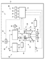
- FIG. 1 is a conceptual diagram of an internal combustion engine and a vehicle equipped with the internal combustion engine according to the first embodiment of the present invention.
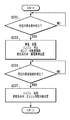
- FIG. 2 is a flowchart of the first embodiment.
- FIG. 3 is a schematic diagram illustrating the flow of electricity, gas, fuel, cooling water, and oil by the operation of the power generation apparatus in a state where the internal combustion engine of FIG. 1 is stopped.
- FIG. 4 is a flowchart of the second embodiment of the present invention.
- FIG. 5 is a conceptual diagram of an internal combustion engine and a vehicle equipped with the same according to a third embodiment of the present invention.
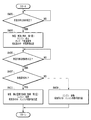
- FIG. 6 is a flowchart of the third embodiment.
- An internal combustion engine (hereinafter simply referred to as an engine) 10 is mounted on a vehicle 12.
- the engine 10 includes an engine main body 14, an intake passage 16 and an exhaust passage 18 connected to the engine main body 14, and a fuel injection device 22 that supplies fuel in a fuel tank (not shown) by operation of a fuel pump 20. .
- the fuel injected from a fuel injection valve (not shown) of the fuel injection device 22 forms an air-fuel mixture with the air guided through the intake passage 16 and is burned in the cylinder of the engine body 14, thereby The exhaust is discharged through the exhaust passage 18.
- an air cleaner and an intake throttle valve are sequentially provided in the intake passage 16 on the upstream end side (both not shown) in order from the upstream side.
- the engine 10 further includes a turbocharger 24.
- a turbine 26 of a turbocharger 24 is disposed in the exhaust passage 18, and a compressor 28 of the turbocharger 24 that accommodates a compressor wheel that is coaxially connected to the turbine wheel of the turbine 26 is disposed in the intake passage 16. Therefore, when the turbine wheel of the turbine 26 is rotationally driven by the exhaust gas guided through the exhaust passage 18, the compressor wheel of the compressor 28 can be rotated and thereby supercharged.
- An intercooler 30 as a cooling device is provided in the intake passage downstream of the compressor 28 to cool the intake air that has been pressurized by the compressor 28 and has risen in temperature.
- valve mechanism 28 for adjusting the amount of exhaust flowing into the turbine 26 of the turbocharger 24 is provided.
- the valve mechanism 28 includes a valve 32, and the valve 32 is provided in a bypass path 34 formed so as to bypass the turbine 26.
- This valve mechanism 28 or valve 32 may typically be referred to as a wastegate valve.
- the valve 32 or the valve mechanism 28 in this embodiment has a mechanical configuration such that when the exhaust pressure becomes equal to or higher than a predetermined pressure, the valve 32 or the valve mechanism 28 is opened by the spring being compressed and the spring is contracted. Is generally closed.
- valve 32 or the valve mechanism 28 may have various other mechanical configurations such as a configuration in which the diaphragm of the actuator is pushed and opened by the supercharging pressure when the supercharging pressure exceeds a predetermined pressure, or It can also be configured as an electromagnetically driven valve.
- the exhaust gas purification device 36 is provided in the exhaust passage 18 so that the exhaust gas that has passed through the turbine 26 and the valve 32 is guided to the exhaust gas purification device 36.
- the exhaust purification device 36 can have various configurations.
- the exhaust purification device 36 can include an oxidation catalyst so that unburned components such as HC and CO react with O 2 to form CO, CO 2 , H 2 O, and the like, or as a so-called three-way catalyst. It can also be configured.
- the exhaust purification device 36 can also have a filter structure such as a particulate filter (DPF) so as to collect particulates (PM; particulates) such as soot in the exhaust, and in this case, an oxidation catalyst is further provided. Can also be provided.
- DPF particulate filter
- the catalyst material of the oxidation catalyst for example, Pt / CeO 2 , Mn / CeO 2 , Fe / CeO 2 , Ni / CeO 2 , Cu / CeO 2 and the like can be used.
- the exhaust purification device 36 may include a NOx catalyst in order to purify NOx (nitrogen oxide) in the exhaust. 1 shows only one exhaust purification device 36, but two or more exhaust purification devices may be provided in series or in parallel. When a plurality of exhaust purification devices are provided, the configurations of the exhaust purification devices may be the same or different.
- the engine 10 includes a power generation device 40.
- the power generation device 40 of the present embodiment is configured as a fuel cell system, and is configured to generate power by an electrochemical reaction between air and fuel.
- the power generation device 40 has a configuration as a solid oxide fuel cell (SOFC).
- SOFC solid oxide fuel cell
- the power generation device 40 is operable when the engine 10 is in an operating state, but is configured to be operable even when the engine 10 is in an inoperative state, as will be described in detail later. Note that the function of the power generation device 40 as a control device or control means is carried out by a part of the ECU described later.
- the power generation device 40 has a power generation main body configured as a fuel cell main body 42.
- An air introduction passage (intake passage of the power generator) 44 is connected to the fuel cell main body 42.
- the air introduction passage 44 is connected to the fuel cell main body 42 so that air is introduced into the fuel cell main body 42.
- a fuel supply passage 46 is connected to the fuel cell main body 42.
- the fuel supply passage 46 is included in a fuel supply device 48, and the device 48 is provided for supplying fuel to the fuel cell main body 42.
- a gas discharge passage (exhaust passage of the power generator) 50 is connected to the fuel cell main body 42.
- the gas discharge passage 50 is connected to the fuel cell main body 42 in order to discharge gas from the fuel cell main body 42.
- the fuel cell main body 42 can be referred to as a cell stack, and has a structure in which a fuel cell as an anode, an air electrode as a cathode, and a single cell made of an electrolyte are connected.
- a fuel cell as an anode
- an air electrode as a cathode
- a single cell made of an electrolyte are connected.
- an oxide ion conductor that is a ceramic is used.
- this invention does not exclude that the fuel cell main-body part 42 does not have a some cell but has only a single cell.
- the fuel supply device 48 includes the pump 20 for supplying fuel in a fuel tank (not shown).
- the fuel supply device 48 is configured integrally with the fuel injection device 22 and includes the fuel tank of the fuel injection device 22 and the fuel pump 20.
- the fuel supply device 48 may have a configuration completely independent of the fuel injection device 22, and in this case, the engine fuel and the power generation fuel may be the same or different.
- the power generation fuel fuels other than fuels such as gasoline and light oil can be used.
- natural gas or propane gas can also be used.
- the power generation device 40 has a configuration as an SOFC and operates at a relatively high temperature (for example, 800 to 1000 ° C.). As a result, internal reforming of the fuel is possible using the high temperature. It is.
- the power generator 40 does not include a fuel reformer.
- the fuel supply device 48 of the power generation device 40 may include a fuel reformer.
- the power generation device 40 may be fabricated to have a configuration as, for example, a polymer electrolyte fuel cell (PEFC), a molten carbonate fuel cell (MCFC), or a phosphoric acid fuel cell (PAFC).
- the supply device 48 may be provided with a necessary type of fuel reformer as required.
- the air introduction passage 44 in the power generation device 40 is connected to the intake passage 16 of the engine 10 so that air that has passed through the compressor 28 can be introduced.
- the air introduction passage 44 is connected to the intake passage downstream of the compressor 28.
- a valve 52 is provided at a connection portion between the air introduction passage 44 and the intake passage 16.
- the valve 52 is configured as an electromagnetically driven valve.
- the valve 52 is a three-way valve, the valve position I allows air to flow to the engine main body 14 and the fuel cell main body 42, and the air flows to the engine main body 14 but the air flows to the fuel cell main body 42.
- valve position II where the air introduction passage 44 is blocked so as not to flow, and the air introduction passage 44 is opened so that air flows to the fuel cell main body 42, but air does not flow to the engine main body 14.
- Valve position I and valve position II may be referred to as engine ready positions, while valve position III may be referred to as a power generation dedicated position.
- the air introduction passage 44 may be directly connected to the compressor 28, and in this case, the air introduction passage 44 is located at the position of the compressor 28 where the air passing through the compressor wheel of the compressor 24 can flow to the air introduction passage 44. Should be connected.
- the intercooler 30 is arranged in the intake passage downstream of the connection portion between the air introduction passage 44 and the intake passage 16. Accordingly, air having a relatively high temperature can be supplied to the fuel cell main body 42, whereas air having a relatively low temperature passing through the intercooler 30 can be supplied to the engine main body 14. Can do.
- the present invention does not exclude that the intercooler 30 is disposed in the intake passage on the upstream side of the connection portion between the air introduction passage 44 and the intake passage 16, but preferably the intake air on the downstream side of the connection portion. Located in the passage. This is because it is preferable to guide warm or hot air to the fuel cell main body 42.
- the gas discharge passage 50 in the power generation apparatus 40 is connected to the exhaust passage 18 of the engine 10 so that exhaust, that is, gas can be supplied to the turbine 26.
- the gas discharge passage 50 is connected to the exhaust passage upstream of the turbine 26.
- the gas exhaust passage 50 may be provided with a valve such as a check valve so that the exhaust gas of the engine 10 does not flow into the gas exhaust passage 50, for example, but such a valve is not provided here.
- a connection portion between the gas discharge passage 50 and the exhaust passage 18 is positioned in the exhaust passage on the upstream side of the bypass passage 34 and the valve 32. Therefore, in addition to being able to pass through the turbine 26, the gas that is the exhaust gas from the gas discharge passage 50 to the exhaust passage 18 can pass through the valve 32 when the valve 32 is opened.
- the gas discharge passage 50 is provided with a reformer 54 for adjusting the gas component.
- the reformer 54 is configured to decompose hydrocarbon components, and has a configuration including an oxidation catalyst as in the exhaust purification device 36, but any other configuration is used. For example, it may have a structure for electrolysis. However, this reformer 54 may not be provided.
- the electricity generated by the power generation apparatus 40 having the above configuration is stored (charged) in the battery 60 (not shown in FIG. 1 but shown in FIG. 3).
- the engine 10 does not include a power generator, specifically an alternator, that converts mechanical kinetic energy transmitted from the engine into electric energy. Therefore, in the engine 10 of the vehicle 12, the power generation device is only the power generation device 40, and the electricity stored in the battery 60 depends only on the power generation device 40.
- the present invention allows a power generation device such as an alternator widely provided in conventional engines to be provided in the engine 10 in addition to the power generation device 40, and is also provided in a so-called hybrid vehicle. It is also permitted to provide a simple power generation device (regenerative power generation device).
- the operation of the starter motor 62 of the engine 10, the operation of the valve 52, and the operation of the fuel pump 20 are performed using electricity stored in the battery 60.
- the electricity of the battery 60 is also used for the operation of the water pump 64 of the coolant supply apparatus configured to cool the turbocharger 24.
- the electricity of the battery 60 is also used for the operation of an oil pump 66 of an oil supply device configured to supply oil, that is, lubricating oil, in the turbocharger 20.
- the power generation device 40 has a configuration as an SOFC, and the temperature control of the stack of the fuel cell main body 42 is not described, but is performed using process air. No water system is needed.
- the power generation apparatus 40 may be provided with a cooling water system, in which case the pump for supplying the cooling water can be driven using the electricity of the battery 60.
- Such operations of the starter motor 62, the valve 52, the fuel pump 20, the water pump 64, and the oil pump 66 are electronic control units (hereinafter referred to as the control device or control means) of the engine 10 and the vehicle 12.
- ECU 70 is configured mainly by a computer or the computer, and includes a storage device such as a CPU, a ROM, and a RAM, an A / D converter, an input interface, an output interface, and the like.
- Various control programs and data are stored in the storage device.
- Various sensors including sensors described later are electrically connected to the input interface.
- the ECU 70 Based on the outputs (detection signals) from these various sensors, the ECU 70 is electrically connected from the output interface so that the engine 10 or the vehicle 12 can be operated or operated smoothly according to a preset program (including data). In response, an operation signal (drive signal) is output.
- the engine 10 and the vehicle 12 include a sensor that electrically outputs signals for detecting (including estimating) various values in the ECU 70. Here, some of them will be specifically described.
- An air flow meter 72 for detecting the amount of intake air is provided in the intake passage 16.
- an accelerator opening sensor 74 for detecting a position corresponding to a depression amount of an accelerator pedal (not shown) operated by the driver, that is, an accelerator opening is provided.
- a crank position sensor 76 for detecting a crank rotation signal of the crankshaft of the engine 10 is attached.
- the crank position sensor 76 is also used as an engine speed sensor for detecting the engine speed.
- a vehicle speed sensor 78 for detecting the speed (vehicle speed) of the vehicle 12 on which the engine 10 is mounted is also provided.
- a stop lamp switch 80 is provided as a brake request detection sensor that outputs a signal corresponding to an operation state of a brake pedal (not shown). The stop lamp switch 80 is turned on when the brake pedal is depressed. Furthermore, a capacity detection sensor 82 for detecting the capacity or remaining capacity of the battery 60 is provided. The capacitance detection sensor 82 is, for example, a current sensor.
- the engine 10 is automatically stopped when a predetermined stop condition is satisfied, and the engine 10 is stopped when a predetermined restart condition (predetermined release condition) is satisfied after the predetermined stop condition is satisfied.
- a stop / restart system 84 is provided to automatically restart 10.
- a function as a control unit or control means in the system 84 is carried by a part of the ECU 70. For example, when the vehicle 12 is running, the engine 10 is temporarily and automatically stopped at a predetermined timing when the vehicle 12 is temporarily stopped based on a traffic light stop display or the like and the engine 10 is in an idling state.
- the ECU 70 performs control to stop and then restart the engine 10 at a predetermined timing, that is, idle reduction control (which may be referred to as idle stop control in Japan).
- the stop condition satisfaction determining means for determining whether a predetermined stop condition is satisfied in the idle reduction control includes a part of the ECU 70. Further, the restart condition satisfaction determining means for determining whether a predetermined restart condition is satisfied includes a part of the ECU 70. Further, the engine stop control means for executing control for stopping the engine 10 such as prohibiting fuel injection from the fuel injection valve is configured to include a part of the ECU 70, and performs control for restarting the engine 10. The engine restart control means to be executed includes a part of the ECU 70. These means are directly or indirectly related to each other.
- the temporary stop of the engine 10 in such idle reduction control is executed by the ECU 70 when a predetermined stop condition is satisfied.
- a predetermined condition a predetermined condition is set such that the vehicle is stopped and a braking operation is being performed. Whether or not the vehicle is stopped is determined based on the output from the vehicle speed sensor 78, and this determination corresponds to determination of whether or not the vehicle speed is zero. Whether or not a braking operation is being performed is determined based on an output from a stop lamp switch 80 serving as a braking operation detection unit. Specifically, this determination corresponds to whether or not the stop lamp switch 80 is ON. .
- the braking operation is being performed when the ECU 70 determines that the accelerator pedal is not depressed based on the output from the accelerator opening sensor 74 as the acceleration request detecting means.
- the starting or restarting of the engine 10 after such a stop of the engine 10 is executed by the ECU 70 when a predetermined restart condition is satisfied.
- a predetermined restart condition a predetermined condition that at least one of the stop conditions is not satisfied is set. For example, when the brake operation is released, that is, when the stop lamp switch 80 is turned from ON to OFF, it is determined that a predetermined restart condition is satisfied. Further, for example, when the accelerator pedal is depressed when the engine 10 is stopped by the idle reduction control, it is determined that a predetermined restart condition is satisfied.
- the engine 10 when the engine 10 is temporarily stopped by such idle reduction control and the engine 10 is restarted, it is desired to improve the operation response of the engine 10. For example, when the engine 10 is restarted because the driver depresses the accelerator pedal, the engine 10 has been stopped until then, so that the engine output corresponding to the depression of the accelerator pedal is changed from the depression of the accelerator pedal. There is a time lag before getting. In addition, even when the driver's foot is simply released from the brake pedal and the vehicle is gradually started, especially when the vehicle 12 includes an automatic transmission, the engine 10 is returned to the state immediately before the engine is stopped. It takes a certain amount of time. In consideration of the driver's sense of maneuvering the vehicle 12, such a time is preferably as short as possible. Therefore, it would be technically very valuable to increase the operating response of the engine 10 when the engine 10 is restarted.
- the power generation device 40 operates until the engine 10 is temporarily stopped by the idle reduction control and the engine 10 is restarted.
- the operation of the power generation device 40 relating to the idle reduction control will be described based on the flowchart of FIG.
- the turbocharger 24 is driven by the operation of the power generation device 40. Therefore, the water pump 64 and the oil pump 66 are electric pumps as described above. Specifically, regardless of the operating state of the engine 10, from when the engine operation start request is received from the driver (for example, after the engine ignition switch is turned ON), until the engine stop request is received from the driver (for example, The water pump 64 and the oil pump 66 are both actuated to facilitate proper driving of the turbocharger 24 (until the engine ignition switch is turned off).
- the flows of gas (including air), fuel, cooling water, and oil when the engine 10 and the power generation device 40 are in an operating state are schematically represented by arrows.
- step S201 of FIG. 2 it is determined whether or not a predetermined stop condition in the idle reduction control is satisfied.
- the predetermined stop condition is as described above.
- engine 10 is maintained in an operating state, that is, an operating state.
- step S201 If an affirmative determination is made in step S201 that a predetermined stop condition has been established, the engine 10 is stopped in step S203, and the power generation apparatus 40 enters an operating state. If the power generation device 40 has been in an operating state, the operation state is maintained, or if the power generation device 40 is in a stopped state at that time, the power generation device 40 is in an operation state.
- the valve (intake system valve) 52 is operatively controlled to introduce all the air that has passed through the compressor 28 into the air introduction passage 44 when the engine 10 is stopped by the system 84.
- the valve 52 is controlled to the power generation dedicated position, that is, the valve position III.
- an intake throttle valve (not shown) is also opened, for example, fully opened.
- the pump 20 may be controlled so that the supply air amount and the supply fuel amount in the power generation device 40 are balanced, or the fuel amount is smaller than the air amount.
- the fuel 20 is supplied to the fuel cell main body 42 by operating the pump 20 of the fuel supply device 48.
- the pump 20 of the fuel supply device 48 As a result, power is generated in the fuel cell main body 42 and gas is discharged through the gas discharge passage 50.
- the valve 32 is basically closed, as shown by an arrow B in FIG. 3, the gas is guided to the turbine 26 and rotationally drives the turbine wheel.
- the turbocharger 24 is driven by operating the power generation device 40.
- FIG. 3 the flow of electricity, the flow of gas, fuel, cooling water, and oil due to the operation of the power generation device 40 in a state where the engine 10 is stopped in this manner is schematically shown by a line C and an arrow. It is represented.
- a line C and an arrow As can be understood from FIG. 3 and the above description, when the engine 10 is stopped by the idle reduction control, electricity is generated by the operation of the power generation device 40, while electricity is consumed. The amount of electricity generated and used is limited by the capacity of the battery 60, it is necessary to prevent overcharging of the battery 60, and the remaining battery capacity needs to be kept above a predetermined amount. Adjusted.
- the part responsible for the function of the ECU 70 as a control device for the oil supply device and the part responsible for the function of the ECU 70 as a control device for the coolant supply device In accordance with the capacity, the operation of both the water pump 64 and the oil pump 66 is controlled so as to control the amount of power, that is, the battery charge amount (operation amount adjustment control). For this purpose, the operation of at least one of the water pump 64 and the oil pump 66 may be controlled.
- step S205 it is determined whether or not a predetermined restart condition in the idle reduction control is satisfied.
- the predetermined restart condition is as described above.
- engine 10 is maintained in the stopped state and power generation device 40 is maintained in the operating state.
- step S207 If it is affirmed in step S205 that the predetermined restart condition is satisfied, the engine 10 is restarted in step S207. At this time, the valve 52 is controlled so that air flows through the engine main body 14 so that the engine 10 is appropriately operated.
- the power generation device 40 When the engine 10 is restarted, the power generation device 40 is maintained in an operating state for at least a certain period. However, when the engine 10 is restarted, the power generation device 40 can be immediately shifted to a stopped state.
- step S205 when the engine 10 is started, the turbocharger 24 is driven as described above.
- the valve 52 is switched to the engine operable position, that is, the valve position I or the valve position II, and the air whose pressure is increased by the compressor 28 is quickly supplied to the engine main body 14. Therefore, the start-up at the restart of the engine 10 can be accelerated, and the operation response of the engine 10 can be enhanced.
- the power generation device 40 is operated, so that the exhaust gas from the power generation device 40 flows into the exhaust purification device 36. Therefore, even when the engine is stopped by the idle reduction control, the exhaust gas purification device 36 can warm up the catalyst. Therefore, the engine stop by the idle reduction control can be allowed even when it is cold.
- the configuration of the engine according to the second embodiment of the present invention and the vehicle on which the engine is mounted are substantially the same as the configuration of the engine 10 according to the first embodiment and the vehicle 12 on which the engine 10 is mounted. Therefore, in the following, the engine and the vehicle according to the second embodiment are not illustrated, and the components corresponding to the components already described are similarly denoted by the reference numerals used in the above description, and the components The duplicate description of is omitted.
- the engine 10 mounted on the vehicle 12 includes a turbocharger 24 and a power generator 40. Then, during the period from the stop of the engine 10 to the restart by the system 84, the power generation device 40 is operated to bring the turbocharger 24 into a driving state, and the operation response of the engine 10 at the time of restart is increased. 12 is configured. This has already been explained.
- the predetermined restart condition in the idle reduction control is satisfied when any of the predetermined stop conditions is not satisfied as described above. For example, when the engine 10 is stopped by the system 84, when the brake operation is released, or when the accelerator pedal is depressed, it is determined that a predetermined restart condition is satisfied. And when the accelerator pedal is depressed, the time when there is a request for acceleration is included.
- steps S401 to S405 and S409 in the flowchart of FIG. 4 generally correspond to steps S201 to S207 of the flowchart of FIG. Therefore, the description of these steps can be largely omitted below.
- step S401 If an affirmative determination is made in step S401 that a predetermined stop condition has been established, the engine 10 is stopped in step S403, and the power generation apparatus 40 enters an operating state. At this time, the fuel supply device 48 of the power generation device 40 operates so that the fuel supply amount becomes the first amount.
- the valve 32 is basically closed. Therefore, the amount of power generated by the power generation device 40 and the amount of gas discharged from the power generation device 40 at this time are determined by the amount of fuel supplied to the fuel cell main body 42. Therefore, here, when the power generation device 40 operates in step S403, in the power generation device 40, the fuel supply is controlled by the portion that functions as a discharge amount increasing means of the ECU 70. In particular, here, based on the output of the air flow meter 72, the fuel supply amount is controlled to the first fuel amount so that the gas discharge amount from the power generation device 40 becomes the first discharge amount.
- the fuel supply in the power generation device 40 can be controlled based on at least one of the air flow meter 72 and an intake pressure sensor provided in the intake passage.
- step S407 it is determined in step S407 whether or not there is an acceleration request.
- the acceleration request means that the driver is required to increase the output of the engine 10.
- the presence / absence of an acceleration request is determined by a portion that functions as an acceleration request determination unit of the ECU 70 in accordance with an output of an accelerator opening sensor 74 as an acceleration request detection unit.
- a predetermined restart condition is satisfied when the engine 10 is in a stopped state by idle reduction control, and the change in the accelerator opening at this time (accelerator opening change speed) is greater than a predetermined amount. When it is determined that there is an acceleration request.
- a predetermined restart condition is established when the driver removes his / her foot from the brake pedal (affirmative determination in step S405). Immediately thereafter, or within a predetermined period from the time when the driver is satisfied, the driver depresses the accelerator pedal. It is also possible to determine in step S407 that there is an acceleration request even when the accelerator opening becomes larger than a predetermined value by stepping on or when the accelerator opening changing speed is larger than a predetermined amount. Thus, when it is determined that there is an acceleration request, the case where the engine 10 is not in a stopped state is included. This is because turbo lag may occur even when there is an acceleration request within a predetermined period after a predetermined restart condition is established.
- the predetermined period is a period in which turbo lag is expected to occur, and may be set by experiment. This predetermined period can be measured by a portion that functions as a timer means of the ECU 70.
- step S407 If there is no acceleration request and a negative determination is made in step S407, the engine 10 is restarted in step S409 as in step S207. That is, in this case, the engine 10 is restarted in a state where the first fuel amount of fuel is supplied and the power generation device 40 is operating. Therefore, the operation response of the engine 10 is based on the supercharging effect by the turbocharger corresponding to the first emission amount gas corresponding to the first fuel amount.
- step S411 When a predetermined restart condition is satisfied, or when there is an acceleration request within a predetermined period after the predetermined restart condition is satisfied, when an affirmative determination is made in step S407, in step S411, The engine 10 is restarted along with the emission increase control by the portion serving as the emission increase means of the ECU 70.
- the part responsible for the function of the emission increase control means of the ECU 70 increases the fuel supply amount in the power generation device 40 from the first fuel amount to the second fuel amount larger than the first fuel amount. Therefore, the amount of gas discharged from the gas discharge passage 50 of the power generation device 40 becomes a second discharge amount that is larger than the first discharge amount when the first fuel amount of fuel is supplied to the power generation device 40.
- step S411 the valve 52 is controlled to the engine operable position.
- the valve 32 when the predetermined stop condition is satisfied, the valve 32 is substantially closed. After that, when there is an acceleration request and the predetermined restart condition is satisfied, the generator 40 The amount of fuel was increased compared to when there was no acceleration request. However, when there is an acceleration request by other control, the amount of gas discharge may be increased.
- the valve 32 when a predetermined stop condition is satisfied, the valve 32 can be controlled to be opened to a predetermined opening (not a closed opening) in step S403.
- the valve 32 may be an electromagnetically driven valve.
- the valve 32 or the valve mechanism 28 is completely closed as the discharge amount increase control, and the amount of air supplied to the air introduction passage 44 is increased. (Air supply increase control).
- the amount of air in the power generation device 40 can be increased as emission amount increase control. Note that it is not necessary to increase the amount of fuel in the power generation device 40 due to the increase in the amount of air.
- the power generation device 40 continues to operate at least until the restart of the engine 10 is completed when an acceleration request is made (Yes in step S407).
- FIG. 1 An engine 110 according to a third embodiment of the present invention and a vehicle 112 on which the engine 110 is mounted are shown in FIG.
- constituent elements corresponding to the constituent elements already described are denoted by reference numerals used in the above description or related reference numerals, and redundant description of those constituent elements is omitted.
- the engine 110 mounted on the vehicle 112 according to the third embodiment is different from the engine 10 mounted on the vehicle 12 in terms of the configuration of the turbocharger 124. Due to this difference in configuration, the configuration of ECU 170 is partially different from the configuration of ECU 70. In other respects, the engine 110 and the vehicle 112 generally have the same configuration as the engine 10 and the vehicle 12, respectively, except for the control described below.
- the turbocharger 124 includes a turbine 126 disposed in the exhaust passage 18 and a compressor 128 disposed in the intake passage 16 that accommodates a compressor wheel coaxially connected to the turbine wheel of the turbine 126. Prepare.
- the turbocharger 124 further includes a variable nozzle mechanism 126 a for changing the opening area of the turbine blade of the turbine wheel of the turbine 126.
- the turbocharger 124 does not include the valve 32 and the bypass path 34.
- the variable nozzle mechanism 126a includes a plurality of nozzle vanes 126b and a drive mechanism 126c.
- the angles of the plurality of nozzle vanes 126b are variable, and the nozzle opening degree can be adjusted by changing the angles by the operation of the drive mechanism 126c.
- the drive mechanism 126c includes a motor whose operation is controlled by the ECU 70. Therefore, in the turbocharger 124, the supercharging pressure can be adjusted by adjusting the nozzle opening degree of the variable nozzle mechanism 126a. Note that during normal travel, the nozzle opening of the variable nozzle mechanism 126a is controlled by a portion serving as a nozzle opening control means of the ECU 70 based on at least one of the engine rotation speed and the engine load.
- an acceleration request is issued when a predetermined restart condition is satisfied or within a predetermined period after the predetermined restart condition is satisfied.
- control is performed to make the operation response of the engine 10 different from that when there is no acceleration request. Such control will be described below based on the flowchart of FIG.
- steps S601 to S611 in the flowchart in FIG. 6 correspond to steps S401 to S411 in the flowchart in FIG. 4 respectively except for parts of steps S603 and S611. Therefore, in the following, the control of the third embodiment will be described by paying attention to the difference between the steps while partially omitting the overlapping description.
- step S601 If an affirmative determination is made in step S601 that a predetermined stop condition has been established, the engine 110 is stopped in step S603, and the power generation apparatus 40 enters an operating state.
- the nozzle opening degree of the variable nozzle mechanism 126a of the turbocharger 124 is set to the first opening degree, and accordingly, a predetermined amount of fuel is supplied to the fuel cell main body 42 with respect to the amount of air introduced from the air introduction passage.
- the fuel supply amount in the power generation device 40 is controlled based on the output of the air flow meter 72, but based on at least one of the air flow meter 72 and an intake pressure sensor provided in the intake passage. The fuel supply amount can also be controlled.
- step S605 when the engine 110 is in a stopped state after the predetermined stop condition is satisfied, if an affirmative determination is made in step S605 that the predetermined restart condition is satisfied, an acceleration request is issued in step S607 as in step S407 above. It is determined whether or not.
- step S607 If there is no acceleration request and a negative determination is made in step S607, the engine 110 is restarted in step S609 as in steps S207 and S409. That is, in this case, the engine 110 is restarted in a state where the nozzle opening of the variable nozzle mechanism 126a is set to the first opening and the power generation apparatus 40 is operated. Therefore, the operation response of the engine 10 is based on the supercharging effect by the turbocharger 124 corresponding to the third emission amount gas corresponding to the nozzle opening.
- step S611 since there is an acceleration request, when an affirmative determination is made in step S607, the engine 110 is restarted in step S611 with the emission increase control.
- the part responsible for the function of the ECU 170 as the emission increase control means controls the nozzle opening degree of the variable nozzle mechanism 126a to the second opening degree that is closer to the throttle side than the first opening degree.
- the fuel supply amount at 40 is also controlled to increase. Therefore, the amount of gas discharged from the gas discharge passage 50 of the power generation device 40 becomes larger than when the nozzle opening of the variable nozzle mechanism 126a is set to the first opening.
- the supercharging effect at the engine 110 by the turbocharger 124 can be enhanced. Therefore, the operation response of the engine 110 can be improved when the engine 110 is restarted at step S611 than when the engine 110 is restarted at step S609.
- step S611 as in step S609, the valve 52 is controlled to the engine operable position.
- the power generation device 40 continues to operate at least until the restart of the engine 110 is completed when an acceleration request is made (Yes in step S607).
- the power generation device 40 is configured as a fuel cell system, but the present invention allows the case where the power generation device has a configuration other than the fuel cell system, and uses various devices as the power generation device. Can do.
Landscapes
- Engineering & Computer Science (AREA)
- Mechanical Engineering (AREA)
- Chemical & Material Sciences (AREA)
- Combustion & Propulsion (AREA)
- General Engineering & Computer Science (AREA)
- Sustainable Development (AREA)
- Life Sciences & Earth Sciences (AREA)
- Sustainable Energy (AREA)
- Transportation (AREA)
- Automation & Control Theory (AREA)
- Power Engineering (AREA)
- Manufacturing & Machinery (AREA)
- Chemical Kinetics & Catalysis (AREA)
- Electrochemistry (AREA)
- General Chemical & Material Sciences (AREA)
- Supercharger (AREA)
- Output Control And Ontrol Of Special Type Engine (AREA)
- Control Of Vehicle Engines Or Engines For Specific Uses (AREA)
Abstract
Description
所定の停止条件が成立したときに内燃機関を自動的に停止させ、該所定の停止条件の成立後に所定の再始動条件が成立したときに同内燃機関を自動的に再始動させるシステム、
該内燃機関の吸気通路に設けられたコンプレッサと該内燃機関の排気通路に設けられたタービンとを備えたターボチャージャ、および、
該コンプレッサを経た空気を導入可能なように吸気通路につなげられた空気導入通路と、該タービンにガスを供給可能なように排気通路につなげられたガス排出通路とがつながる発電本体部を有する発電装置であって、上記システムにより内燃機関が停止されているときに少なくとも作動するように構成された、発電装置
を備えた、内燃機関を提供する。
Claims (11)
- 所定の停止条件が成立したときに内燃機関を自動的に停止させ、該所定の停止条件の成立後に所定の再始動条件が成立したときに同内燃機関を自動的に再始動させるシステム、
該内燃機関の吸気通路に設けられたコンプレッサと該内燃機関の排気通路に設けられたタービンとを備えたターボチャージャ、および、
該コンプレッサを経た空気を導入可能なように前記吸気通路につなげられた空気導入通路と、該タービンにガスを供給可能なように前記排気通路につなげられたガス排出通路とがつながる発電本体部を有する発電装置であって、前記システムにより前記内燃機関が停止されているときに少なくとも作動するように構成された、発電装置
を備えた、内燃機関。 - 前記発電装置は燃料電池システムとして構成され、前記発電本体部は燃料電池本体部として構成されている、請求項1に記載の内燃機関。
- 前記空気導入通路と前記吸気通路との接続部よりも下流側の吸気通路に冷却装置が備えられている、請求項1または2に記載の内燃機関。
- 前記空気導入通路と前記吸気通路との接続部には弁が設けられ、
該弁は、前記システムにより前記内燃機関が停止されているときに、前記コンプレッサを経た全空気を前記空気導入通路に導入するように作動される、
請求項1から3のいずれかに記載の内燃機関。 - 前記ターボチャージャにおいてオイルを供給するように構成されたオイル供給装置、および、前記ターボチャージャを冷却するように構成された冷却液供給装置は、前記発電装置につながれたバッテリからの電気で作動可能であり、前記システムにより前記内燃機関が停止されているときに作動する、請求項1から4のいずれかに記載の内燃機関。
- 前記オイル供給装置および前記冷却液供給装置の少なくとも一方は、前記バッテリの充電量を制御するように作動する、請求項5に記載の内燃機関。
- 前記所定の再始動条件が成立したときに、または、該所定の再始動条件の成立後の所定期間内に、加速要求があったとき、該加速要求が無い場合に比べて、前記発電装置からのガスの排出量を増大させる排出量増大制御手段をさらに備える、請求項1から6のいずれかに記載の内燃機関。
- 前記排出量増大制御手段は、前記空気導入通路への空気供給量の増量制御および前記発電本体部への燃料供給量の増量制御のうちの少なくとも一方を実行することにより、ガスの排出量を増大させる、請求項7に記載の内燃機関。
- 前記タービンへの排気の流入量を調節するための弁機構をさらに備え、
前記排出量増大制御手段は、加速要求があったとき、該加速要求が無い場合に比べて、前記タービンへの排気の流入量を増やすように前記弁機構を制御するか、または、前記発電本体部への燃料供給量の増量制御を実行する、請求項8に記載の内燃機関。 - 前記ターボチャージャは前記タービンのタービンブレードの開口面積を変化させるための可変ノズル機構をさらに備え、
前記排出量増大制御手段は、加速要求があったとき、該加速要求が無い場合に比べて、前記タービンブレードの回転速度を高めるように前記可変ノズル機構を制御し、かつ、前記発電本体部への燃料供給量の増量制御を実行する、請求項8に記載の内燃機関。 - 請求項1から10のいずれかに記載の内燃機関を備えた、車両。
Priority Applications (6)
| Application Number | Priority Date | Filing Date | Title |
|---|---|---|---|
| RU2014123317/06A RU2566092C1 (ru) | 2011-12-09 | 2011-12-09 | Двигатель внутреннего сгорания |
| CN201180075371.0A CN103975147B (zh) | 2011-12-09 | 2011-12-09 | 内燃机 |
| US14/363,317 US20140350824A1 (en) | 2011-12-09 | 2011-12-09 | Internal combustion engine |
| EP11877163.3A EP2789832A4 (en) | 2011-12-09 | 2011-12-09 | COMBUSTION ENGINE |
| PCT/JP2011/006900 WO2013084273A1 (ja) | 2011-12-09 | 2011-12-09 | 内燃機関 |
| JP2013547970A JP5768897B2 (ja) | 2011-12-09 | 2011-12-09 | 内燃機関 |
Applications Claiming Priority (1)
| Application Number | Priority Date | Filing Date | Title |
|---|---|---|---|
| PCT/JP2011/006900 WO2013084273A1 (ja) | 2011-12-09 | 2011-12-09 | 内燃機関 |
Publications (1)
| Publication Number | Publication Date |
|---|---|
| WO2013084273A1 true WO2013084273A1 (ja) | 2013-06-13 |
Family
ID=48573684
Family Applications (1)
| Application Number | Title | Priority Date | Filing Date |
|---|---|---|---|
| PCT/JP2011/006900 Ceased WO2013084273A1 (ja) | 2011-12-09 | 2011-12-09 | 内燃機関 |
Country Status (6)
| Country | Link |
|---|---|
| US (1) | US20140350824A1 (ja) |
| EP (1) | EP2789832A4 (ja) |
| JP (1) | JP5768897B2 (ja) |
| CN (1) | CN103975147B (ja) |
| RU (1) | RU2566092C1 (ja) |
| WO (1) | WO2013084273A1 (ja) |
Cited By (1)
| Publication number | Priority date | Publication date | Assignee | Title |
|---|---|---|---|---|
| WO2025009234A1 (ja) * | 2023-07-05 | 2025-01-09 | 株式会社Ihi | 電動過給機 |
Families Citing this family (13)
| Publication number | Priority date | Publication date | Assignee | Title |
|---|---|---|---|---|
| FR3013683B1 (fr) * | 2013-11-27 | 2017-07-07 | Microturbo | Procede et systeme pour la production optimisee d'energie non propulsive |
| SE540370C2 (en) * | 2014-04-29 | 2018-08-21 | Scania Cv Ab | Förfarande samt system för styrning av ett överladdningssystem vid ett motorfordon |
| US10128516B2 (en) * | 2014-07-24 | 2018-11-13 | Nissan Motor Co., Ltd. | Fuel cell system |
| CN104564343A (zh) * | 2015-01-09 | 2015-04-29 | 哈尔滨东安发动机(集团)有限公司 | 微型燃机超功率快速补偿装置 |
| DE102015002596A1 (de) * | 2015-02-28 | 2016-09-01 | Man Truck & Bus Ag | Verfahren und Vorrichtung zur Ansteuerung eines Antriebssystems eines Kraftfahrzeugs mit einem Nebenabtrieb |
| JP6038271B1 (ja) * | 2015-12-24 | 2016-12-07 | 三菱電機株式会社 | 内燃機関の制御装置および内燃機関の制御方法 |
| JP7014126B2 (ja) * | 2018-10-17 | 2022-02-01 | トヨタ自動車株式会社 | 電池冷却システム |
| CN109681334B (zh) * | 2018-11-02 | 2022-01-21 | 浙江吉利新能源商用车有限公司 | 双燃料发动机启停的控制方法、装置及车辆 |
| US20210207540A1 (en) * | 2020-01-02 | 2021-07-08 | United Technologies Corporation | Systems and methods for fuel cell auxiliary power in secondary fuel applications |
| CN111946454A (zh) * | 2020-07-24 | 2020-11-17 | 江苏大学 | 内燃机与燃料电池联合发电装置及控制方法 |
| EP3961084A1 (en) * | 2020-08-27 | 2022-03-02 | Ecole Polytechnique Fédérale de Lausanne (EPFL) | Compressed natural gas (cng) power system with co2 emissions capture and storage |
| US11156179B1 (en) * | 2020-09-30 | 2021-10-26 | GM Global Technology Operations LLC | System and method for controlling airflow through cylinders of an engine during a deceleration fuel cutoff event |
| FR3144068B1 (fr) * | 2022-12-21 | 2024-11-08 | Renault Sas | Procédé de gestion d’un groupe motopropulseur hybride pour véhicule automobile à hydrogène et groupe motopropulseur associé |
Citations (6)
| Publication number | Priority date | Publication date | Assignee | Title |
|---|---|---|---|---|
| JP2006177171A (ja) * | 2004-12-20 | 2006-07-06 | Toyota Motor Corp | 電動機付き過給機の制御装置及びその制御装置を備えた自動車 |
| JP2006183629A (ja) | 2004-12-28 | 2006-07-13 | Nissan Motor Co Ltd | 内燃機関及びその制御方法 |
| JP2007016641A (ja) * | 2005-07-06 | 2007-01-25 | Toyota Motor Corp | ハイブリッドシステム |
| JP2008095669A (ja) | 2006-10-16 | 2008-04-24 | Toyota Motor Corp | 車両の制御装置 |
| JP2008513285A (ja) * | 2004-09-17 | 2008-05-01 | イートン コーポレーション | クリーンな動力システム |
| JP2010129293A (ja) * | 2008-11-26 | 2010-06-10 | Honda Motor Co Ltd | 燃料電池車両 |
Family Cites Families (12)
| Publication number | Priority date | Publication date | Assignee | Title |
|---|---|---|---|---|
| US5929595A (en) * | 1997-11-21 | 1999-07-27 | Lockheed Martin Corporation | Hybrid electric vehicle with traction motor drive allocated between battery and auxiliary source depending upon battery charge state |
| DE19913794C2 (de) * | 1999-03-26 | 2002-11-14 | Xcellsis Gmbh | Fahrzeug mit einem Antriebsstrang für wenigstens zwei Antriebsräder und mit einem Brennkraftmaschinen-Antrieb sowie mit einem Brennstoffzellensystem |
| US7818959B2 (en) * | 2004-09-17 | 2010-10-26 | Eaton Corporation | Clean power system |
| EP2267286A1 (de) * | 2005-09-01 | 2010-12-29 | AVL List GmbH | Verfahren zum Betreiben einer Brennkraftmaschine |
| RU2392142C2 (ru) * | 2007-11-20 | 2010-06-20 | Федеральное государственное унитарное предприятие "Центральный ордена Трудового Красного Знамени научно-исследовательский автомобильный и автомоторный институт "НАМИ" | Способ управления комбинированной энергоустановкой |
| US8397499B2 (en) * | 2009-08-24 | 2013-03-19 | Ford Global Technologies, Llc | Methods and systems for turbocharger control |
| DE102010043920B4 (de) * | 2010-11-15 | 2014-09-11 | Ford Global Technologies, Llc | Verfahren zum Vermeiden von Turboladerschäden |
| JP2013161616A (ja) * | 2012-02-03 | 2013-08-19 | Toyota Motor Corp | 内燃機関 |
| JP2013185506A (ja) * | 2012-03-08 | 2013-09-19 | Toyota Motor Corp | 内燃機関 |
| JP5724935B2 (ja) * | 2012-04-19 | 2015-05-27 | トヨタ自動車株式会社 | エンジンシステム |
| JP2014072144A (ja) * | 2012-10-01 | 2014-04-21 | Toyota Motor Corp | 内燃機関 |
| JP5831430B2 (ja) * | 2012-11-14 | 2015-12-09 | トヨタ自動車株式会社 | 内燃機関 |
-
2011
- 2011-12-09 JP JP2013547970A patent/JP5768897B2/ja not_active Expired - Fee Related
- 2011-12-09 WO PCT/JP2011/006900 patent/WO2013084273A1/ja not_active Ceased
- 2011-12-09 US US14/363,317 patent/US20140350824A1/en not_active Abandoned
- 2011-12-09 EP EP11877163.3A patent/EP2789832A4/en not_active Withdrawn
- 2011-12-09 RU RU2014123317/06A patent/RU2566092C1/ru not_active IP Right Cessation
- 2011-12-09 CN CN201180075371.0A patent/CN103975147B/zh not_active Expired - Fee Related
Patent Citations (6)
| Publication number | Priority date | Publication date | Assignee | Title |
|---|---|---|---|---|
| JP2008513285A (ja) * | 2004-09-17 | 2008-05-01 | イートン コーポレーション | クリーンな動力システム |
| JP2006177171A (ja) * | 2004-12-20 | 2006-07-06 | Toyota Motor Corp | 電動機付き過給機の制御装置及びその制御装置を備えた自動車 |
| JP2006183629A (ja) | 2004-12-28 | 2006-07-13 | Nissan Motor Co Ltd | 内燃機関及びその制御方法 |
| JP2007016641A (ja) * | 2005-07-06 | 2007-01-25 | Toyota Motor Corp | ハイブリッドシステム |
| JP2008095669A (ja) | 2006-10-16 | 2008-04-24 | Toyota Motor Corp | 車両の制御装置 |
| JP2010129293A (ja) * | 2008-11-26 | 2010-06-10 | Honda Motor Co Ltd | 燃料電池車両 |
Non-Patent Citations (1)
| Title |
|---|
| See also references of EP2789832A4 |
Cited By (1)
| Publication number | Priority date | Publication date | Assignee | Title |
|---|---|---|---|---|
| WO2025009234A1 (ja) * | 2023-07-05 | 2025-01-09 | 株式会社Ihi | 電動過給機 |
Also Published As
| Publication number | Publication date |
|---|---|
| RU2566092C1 (ru) | 2015-10-20 |
| US20140350824A1 (en) | 2014-11-27 |
| CN103975147B (zh) | 2017-05-24 |
| CN103975147A (zh) | 2014-08-06 |
| EP2789832A4 (en) | 2016-06-08 |
| EP2789832A1 (en) | 2014-10-15 |
| JP5768897B2 (ja) | 2015-08-26 |
| JPWO2013084273A1 (ja) | 2015-04-27 |
Similar Documents
| Publication | Publication Date | Title |
|---|---|---|
| JP5768897B2 (ja) | 内燃機関 | |
| JP5601362B2 (ja) | 内燃機関 | |
| JP4325704B2 (ja) | 内燃機関の排気浄化システム | |
| US8468801B2 (en) | Method and system for warming up catalytic converter for cleaning up exhaust gas | |
| US20160137187A1 (en) | Control apparatus for hybrid vehicle | |
| JP6288131B2 (ja) | 気体燃料エンジンの制御装置 | |
| JP2013161616A (ja) | 内燃機関 | |
| JP2013185506A (ja) | 内燃機関 | |
| JP2014141934A (ja) | 内燃機関 | |
| CN111749767B (zh) | 混合动力车辆 | |
| CN111794839B (zh) | 混合动力车辆 | |
| JP2014125898A (ja) | 駆動システム | |
| JP2003020981A (ja) | 内燃機関の始動時制御装置 | |
| JP2014072144A (ja) | 内燃機関 | |
| JP2014139425A (ja) | 内燃機関 | |
| JP5831430B2 (ja) | 内燃機関 | |
| JP4635913B2 (ja) | エンジンの排気浄化装置 | |
| JP2007239468A (ja) | エンジンの排気浄化装置 | |
| JP2014163239A (ja) | 内燃機関 | |
| JP2007278252A (ja) | ターボチャージャ制御装置 | |
| JP2017214893A (ja) | 排気駆動発電機を備えたエンジン | |
| JP7831440B2 (ja) | 内燃機関の異常判定装置、及び内燃機関の異常判定プログラム | |
| JP6183384B2 (ja) | 多種燃料エンジンの燃料制御装置 | |
| JP2007332822A (ja) | 過給機付き内燃機関の制御装置 | |
| JP2021139330A (ja) | 内燃機関の制御装置 |
Legal Events
| Date | Code | Title | Description |
|---|---|---|---|
| 121 | Ep: the epo has been informed by wipo that ep was designated in this application |
Ref document number: 11877163 Country of ref document: EP Kind code of ref document: A1 |
|
| ENP | Entry into the national phase |
Ref document number: 2013547970 Country of ref document: JP Kind code of ref document: A |
|
| REEP | Request for entry into the european phase |
Ref document number: 2011877163 Country of ref document: EP |
|
| WWE | Wipo information: entry into national phase |
Ref document number: 14363317 Country of ref document: US Ref document number: 2011877163 Country of ref document: EP |
|
| NENP | Non-entry into the national phase |
Ref country code: DE |
|
| ENP | Entry into the national phase |
Ref document number: 2014123317 Country of ref document: RU Kind code of ref document: A |