WO2013084755A1 - 検査用照明装置及び検査用照明方法 - Google Patents
検査用照明装置及び検査用照明方法 Download PDFInfo
- Publication number
- WO2013084755A1 WO2013084755A1 PCT/JP2012/080648 JP2012080648W WO2013084755A1 WO 2013084755 A1 WO2013084755 A1 WO 2013084755A1 JP 2012080648 W JP2012080648 W JP 2012080648W WO 2013084755 A1 WO2013084755 A1 WO 2013084755A1
- Authority
- WO
- WIPO (PCT)
- Prior art keywords
- inspection
- diaphragm
- light source
- lens
- solid angle
- Prior art date
- Legal status (The legal status is an assumption and is not a legal conclusion. Google has not performed a legal analysis and makes no representation as to the accuracy of the status listed.)
- Ceased
Links
Images





Classifications
-
- G—PHYSICS
- G01—MEASURING; TESTING
- G01B—MEASURING LENGTH, THICKNESS OR SIMILAR LINEAR DIMENSIONS; MEASURING ANGLES; MEASURING AREAS; MEASURING IRREGULARITIES OF SURFACES OR CONTOURS
- G01B11/00—Measuring arrangements characterised by the use of optical techniques
- G01B11/30—Measuring arrangements characterised by the use of optical techniques for measuring roughness or irregularity of surfaces
-
- G—PHYSICS
- G01—MEASURING; TESTING
- G01N—INVESTIGATING OR ANALYSING MATERIALS BY DETERMINING THEIR CHEMICAL OR PHYSICAL PROPERTIES
- G01N21/00—Investigating or analysing materials by the use of optical means, i.e. using sub-millimetre waves, infrared, visible or ultraviolet light
- G01N21/84—Systems specially adapted for particular applications
- G01N21/88—Investigating the presence of flaws or contamination
- G01N21/8806—Specially adapted optical and illumination features
-
- G—PHYSICS
- G01—MEASURING; TESTING
- G01N—INVESTIGATING OR ANALYSING MATERIALS BY DETERMINING THEIR CHEMICAL OR PHYSICAL PROPERTIES
- G01N21/00—Investigating or analysing materials by the use of optical means, i.e. using sub-millimetre waves, infrared, visible or ultraviolet light
- G01N21/84—Systems specially adapted for particular applications
- G01N21/88—Investigating the presence of flaws or contamination
- G01N21/8806—Specially adapted optical and illumination features
- G01N2021/8809—Adjustment for highlighting flaws
-
- G—PHYSICS
- G01—MEASURING; TESTING
- G01N—INVESTIGATING OR ANALYSING MATERIALS BY DETERMINING THEIR CHEMICAL OR PHYSICAL PROPERTIES
- G01N21/00—Investigating or analysing materials by the use of optical means, i.e. using sub-millimetre waves, infrared, visible or ultraviolet light
- G01N21/84—Systems specially adapted for particular applications
- G01N21/88—Investigating the presence of flaws or contamination
- G01N21/8806—Specially adapted optical and illumination features
- G01N2021/8835—Adjustable illumination, e.g. software adjustable screen
-
- G—PHYSICS
- G01—MEASURING; TESTING
- G01N—INVESTIGATING OR ANALYSING MATERIALS BY DETERMINING THEIR CHEMICAL OR PHYSICAL PROPERTIES
- G01N2201/00—Features of devices classified in G01N21/00
- G01N2201/06—Illumination; Optics
- G01N2201/068—Optics, miscellaneous
Definitions
- the present invention relates to an inspection illumination device and an inspection illumination method used to irradiate a product to be inspected with inspection light and inspect the appearance, scratches, defects, etc. of the product.
- an inspection illumination device used for an appearance inspection of a product there is a coaxial illumination in which the image capturing direction and the direction to illuminate the inspection object are matched as shown in Patent Document 1.
- the coaxial illumination is provided to be inclined between a light source that emits inspection light in a horizontal direction, the inspection object, and an imaging device provided above the inspection object, and the inspection light is supplied to the inspection object.
- a half mirror arranged so that the reflected light from the inspection object is transmitted to the imaging device side.
- the inspection object may be a flat surface, or may be slightly convex or concave, and the inclination of the irradiation solid angle at each point of the inspection object is not in a form suitable for the inspection object.
- this may cause failure in defect detection.
- the present invention has been made in view of the above-described problems. For example, even when illumination conditions are severe or feature points such as defects are very small and fine, light at the feature points is detected by inspection light. It is an object of the present invention to provide an inspection illumination device and an inspection illumination method capable of making a difference such as a light / dark difference appear depending on the amount of change in. More specifically, most of the emitted inspection light can be made to reach the inspection object, the inclination of the irradiation solid angle of the inspection light at each point of the inspection object, and the size of the irradiation solid angle Provided are an inspection illumination device and an inspection illumination method that can be adjusted and inspected according to the shape and characteristics of an inspection object.
- the inspection illumination device of the present invention includes a surface light source that emits inspection light, a lens that is on the optical axis of the inspection light emitted from the surface light source, and is provided between the inspection object and the surface light source.
- a first diaphragm provided between the surface light source and the lens or between the lens and the inspection object, and the positions of the surface light source and the lens with respect to the inspection object are connected to the surface light source.
- the imaging plane to be imaged is set to be in the vicinity of the inspection target, and the central axis of the irradiation solid angle defined by the inspection light incident on the outer edge portion of the imaging plane is relative to the optical axis.
- the position of the first diaphragm with respect to the lens is set so as to be parallel or shifted from the optical axis and tilted by a predetermined amount.
- the inspection illumination method of the present invention includes a surface light source that emits inspection light, a lens that is on the optical axis of the inspection light emitted from the surface light source, and is provided between the inspection object and the surface light source.
- An inspection illumination method used in an inspection illumination device comprising: a first diaphragm provided between the surface light source and the lens or between the lens and the inspection object, the surface light source and An imaging position setting step for setting the position of the lens with respect to the inspection object so that an imaging surface on which the surface light source forms an image is in the vicinity of the inspection object, and an inspection that enters the outer edge of the imaging surface Irradiation that sets the position of the first diaphragm with respect to the lens so that the central axis of the illumination solid angle defined by light is parallel to the optical axis or is deviated from the optical axis and tilted by a predetermined amount Solid angle tilt adjustment step, And said that there were pictures.
- the surface light source and the position of the lens with respect to the inspection object are set so that the imaging surface on which the surface light source forms an image is in the vicinity of the inspection object, the surface The inspection light emitted from the light source can be limited to only the inspection object without being blocked.
- the central axis of the irradiation solid angle defined by the inspection light incident on the outer edge portion of the imaging plane with respect to the position of the first diaphragm with respect to the lens is parallel to the optical axis, or the optical axis Since they are arranged so as to be deviated and tilted by a predetermined amount, the solid angle of the inspection light applied to each point to be inspected can be set to an inclination suitable for detecting a feature point such as a defect. Further, since the first diaphragm is disposed in a state where the imaging plane is in the vicinity of the inspection object, the range irradiated with the inspection light is changed with the size of the imaging plane being changed. The size of the irradiation solid angle can be changed.
- the inspection light irradiation range and irradiation solid angle can be adjusted independently.
- the inspection light irradiation can be performed according to the feature point such as a defect that occurs in the inspection object and the size and shape characteristics of the location to be inspected.
- the irradiation solid angle of the inspection light can be adjusted to be small. Therefore, the solid angle of the reflected light generated by the inspection light reflected from the inspection object can be reduced, and the solid angle of the reflected light is small even if the reflection direction of the reflected light changes only slightly due to feature points such as defects. For this reason, most of the solid angle of the reflected light deviates from the observation solid angle of the image pickup device, and it is easy to detect a feature point such as a defect as a difference in brightness.
- the inspection target has a convex surface
- the direction of the solid angle of the reflected light at each point of the convex surface of the inspection target is substantially parallel to the optical axis
- the first diaphragm is disposed outside the focal point of the lens so that the central axis of the irradiation solid angle is inclined from the outer edge side to the center side of the imaging plane.
- the central axis of the irradiation solid angle is disposed inside the focal point of the lens so that is inclined from the center side to the outer edge side of the imaging plane.
- the center axis of the irradiation solid angle is parallel to the optical axis to facilitate defect inspection and the like. It is sufficient that the first diaphragm is disposed at the focal point of the lens so that
- the position of the first diaphragm is an angle formed by the central axis of the irradiation solid angle and the optical axis. As long as the surface light source is set based on the magnification of the imaging surface formed by the lens.
- the light is emitted from the surface light source. What is necessary is just to provide the 2nd aperture_diaphragm
- the reflected light from the inspection object can prevent stray light such as reflection from a part unrelated to the inspection, and the irradiation range of the inspection light to the inspection object and the solid angle of the reflected light are suitable for the inspection.
- a third diaphragm is further provided between the inspection object and an imaging device that images the inspection object.
- the third diaphragm, the imaging device, A fourth diaphragm may be further provided between the two.
- the inspection light emitted from the light source is reflected to the inspection object, and the reflected light from the inspection object is reflected.
- a reflection mirror including an irradiation optical path that is an optical path from the light source to the inspection object and at least an optical path from the inspection object to the half mirror; What is necessary is just to arrange
- the size of the solid angle of the inspection light irradiated on the inspection target and the inclination with respect to the optical axis are appropriately adjusted by the first diaphragm.
- the solid angle of the reflected light from the inspection object can be changed as appropriate. Therefore, it is a feature point such as a minute defect, and the inclusion relationship between the solid angle of the reflected light and the observation solid angle of the imaging device etc. is optimal even if it was difficult to show the contrast in the captured image in the past. Therefore, a difference in brightness can be generated.
- the irradiation range of the inspection light irradiated to the inspection object can be appropriately set independently of the control of the irradiation solid angle. In other words, since the inspection light irradiation range and the solid angle of irradiation at each point in the irradiation range can be controlled independently, it is possible to easily detect objects and defects that were difficult to inspect by machine vision etc. Become.
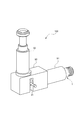
- the typical perspective view which shows the external appearance of the illuminating device for a test
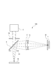
- the schematic diagram which simplifies and shows the optical path of the illuminating device for a test
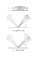
- the schematic diagram which shows the example of a change of the irradiation solid angle by the 1st aperture_diaphragm
- the schematic diagram which shows the example of the illuminating device for a test
- the schematic diagram which simplifies and shows the optical path of the illuminating device for a test
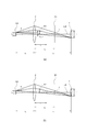
- the schematic diagram which shows the image formation state of the inspection illuminating device in 2nd Embodiment, and the change by arrangement
- the schematic diagram which shows that the magnitude
- restriction of the inspection illuminating device in 2nd Embodiment The schematic diagram which shows the inclination distribution of the irradiation solid angle by the position of the 1st aperture_diaphragm
- the inspection illumination device 100 is so-called coaxial illumination in which the direction in which the inspection target W is imaged by the imaging device C matches the direction in which the inspection target W is illuminated. This is used to cause a defect to appear as a light / dark difference in an image picked up by the image pickup apparatus C.
- the feature points such as defects of the inspection target W include various defects such as scratches on the surface, appearance shape, presence / absence of holes, and other feature quantities.
- the inspection illumination device 100 has a substantially L-shaped housing, and inspects the inspection light from the light source 1 to the inspection object W.
- An irradiation light path L1 for irradiating the light beam and a reflection light path L2 until the reflected light from the inspection object W reaches the imaging device C are formed. More specifically, a first cylindrical body 91 extending in the horizontal direction and a second cylindrical body 92 extending in the vertical direction are respectively connected to the box body 93, and the second cylindrical body extending in the vertical direction.
- the imaging device C is attached to the upper surface opening side of 92, and the inspection object W is placed on the lower surface opening of the box 93.
- the irradiation optical path L1 is formed in an L shape, and the first optical path L11 in which the inspection light travels in the horizontal direction and reflected downward.
- the second optical path L12 travels.
- the light source 1 that emits the inspection light, the second diaphragm 32 provided in the vicinity of the light source 1, and the inspection light emitted from the light source 1 are arranged in the order in which the inspection light travels.
- the condensing lens 2, the first diaphragm 31 provided in the vicinity of the light incident side of the lens 2, and the inclined light path L2 and the irradiation light path L1 are provided so as to reflect the inspection light downward.
- the half mirror 4 is disposed. Furthermore, a third diaphragm 33 through which the inspection light reflected by the half mirror 4 passes is provided on the second optical path L12. Then, the inspection light that has passed through the third diaphragm 33 from inside the box 93 is irradiated onto the inspection object W.
- the third diaphragm 33, the half mirror 4, and the fourth attached to the upper surface of the box 93 are arranged in the order in which the reflected light reflected from the inspection object W proceeds.
- a diaphragm 34 is provided up to the imaging device C. That is, the half mirror 4 and the third diaphragm 33 are arranged in a portion where the irradiation light path L1 and the reflection light path L2 overlap.
- the first diaphragm 31, the second diaphragm 32, the third diaphragm 33, and the fourth diaphragm 34 described above are variable diaphragms, and the amount of diaphragm can be changed as appropriate. Further, a fixed aperture with a fixed aperture amount may be used depending on the use mode.
- the surface light source 1 has a light emission surface 11 formed of, for example, a chip-type LED, and heat radiating fins 12 are discharged toward the outside. As shown in the sectional view of FIG. 2, the surface light source 1 is attached so as to be able to advance and retreat in the axial direction in the first cylindrical body 91 so that the irradiation start position of the inspection light can be adjusted. . That is, independent of the control of the irradiation solid angle by the first diaphragm 31 to be described later, the positional relationship among the surface light source 1, the lens 2, and the inspection target W is changed, so that the inspection light in the inspection target W is changed. The irradiation range can be controlled.
- the second diaphragm 32 is provided in the vicinity of the light emission surface 11 of the surface light source 1, and the irradiation area of the inspection light of the surface light source 1 is changed by adjusting the amount of the diaphragm, and the inspection object The irradiation range of the inspection light at W can be changed.
- the lens 2 is attached to a side opening of the box 93, and is arranged so that an image forming surface, which is an image forming position of the light source, is positioned in the vicinity of the surface of the inspection object W.
- the first diaphragm 31 is provided on the light emission side of the lens 2 and is equally irradiated with the inspection light focused on each point within the irradiation range with respect to the surface of the inspection object W by the lens 2. It is for adjusting the angle. That is, by changing the aperture amount of the first diaphragm, any irradiation solid angle that is smaller than the maximum irradiation solid angle determined by the aperture diameter of the lens 2 as shown in the schematic diagram of FIG.
- the inspection light W can be irradiated with inspection light at a solid angle.
- the half mirror 4 is a circular thin wall supported by a substantially square frame 41.
- a portion where reflection or transmission of the half mirror 4 occurs can be formed thin, and a minute amount generated when reflected light from the inspection object W passes through the half mirror 4.
- An imaging error due to refraction or the like can be minimized.
- the third diaphragm 33 is attached to the opening on the lower surface of the box 93 and is disposed between the half mirror 4 and the inspection object W. With the third diaphragm 33, fine adjustment can be further performed from the irradiation solid angle determined by the first diaphragm 31. In addition, the third diaphragm 33 prevents stray light from entering the inspection light irradiation device when inspection light that has passed through the third diaphragm 33 is reflected by the inspection object W and becomes reflected light. Can do. In addition, the aperture allows the illumination solid angle and the observation solid angle to be precisely the same size on the same axis, and changes the tilt variation of the reflected light as the density information of the observation light observed by the imaging device C. It is possible to change the sensitivity characteristic and the light / dark profile.
- the fourth diaphragm 34 is attached to the upper surface opening of the box 93 and is disposed between the half mirror 4 and the imaging device C.
- the fourth diaphragm 34 is for further adjusting the observation solid angle for observing the reflected light incident on the imaging device C.
- the second cylindrical body 92 is attached to be extendable and contractible so that the distance between the fourth diaphragm 34 and the imaging device C can be adjusted. As a result, it is possible to optimize the light and shade profile with respect to the tilt variation of the reflected light more precisely.
- the irradiation solid angle indicated by the dotted line in FIG. 5 is a conventional example when the irradiation solid angle cannot be adjusted without the first diaphragm 31, and the solid line indicates the irradiation in the inspection illumination device 100 of the present embodiment. An example in which the solid angle is reduced is shown.
- the inspection light and the reflected light appear as mirror image symmetry by specular reflection.
- the reflection direction of the reflected light slightly changes. At this time, if the defect is minute, the change in the direction of the reflected light also becomes small. Therefore, when the inspection light is irradiated with the irradiation solid angle of the conventional example indicated by the dotted line, the solid angle of the reflected light also increases accordingly. Thus, the reflected light does not deviate from the observation solid angle C1 of the imaging device C.
- the observation solid angle of the imaging device C is changed even when the inclination of the reflected light is slightly changed.
- C1 is arranged outside the solid angle of the reflected light and is imaged darkly.
- the irradiation solid angle and the solid angle of the reflected light can be appropriately set by the first diaphragm 31, so that a defect or the like that could not be detected conventionally can be recognized as a light / dark difference in machine vision.
- this variation in shade is based on the size of each of the solid angle and the observation solid angle of the reflected light returned from the object, and its inclusion relationship, and the variation range, variation start point, variation end point, variation variation. The degree is determined. Since the solid angle of the reflected light can be controlled by the solid angle of the irradiating light, the present invention, which can be controlled uniformly in the field of view, can be used to obtain a desired tone profile for feature points such as defects on the object surface. Can be obtained.
- the inclination of the solid angle of the reflected light is adjusted in accordance with the inclination change of the observation solid angle in the visual field range. By controlling it, it becomes possible to obtain uniform shading fluctuations for defects and the like.
- Optimal control of the inclination of the solid angle of the reflected light within the visual field range can be realized by appropriately selecting the position of the first diaphragm 31 on the optical axis.
- the inspection light irradiation device is configured as coaxial illumination.
- the inspection light irradiation device is configured separately so that the irradiation light path L1 and the reflected light path L2 do not have overlapping portions. It doesn't matter.
- the inspection light emitted from the surface light source 1 is condensed by the lens 2 having a focal point set on the inspection object W, and the inspection light is irradiated by the first diaphragm 31 provided in the vicinity of the lens 2. Any device can be used as long as the solid solid angle can be adjusted.
- the second diaphragm 32, the third diaphragm 33, and the fourth diaphragm 34 may be used as necessary.
- the focal position of the lens is not limited to the surface to be inspected, and may be slightly shifted back and forth from the surface as long as it is in the vicinity.
- inspection objects, defects, and the like are not limited to specific ones, and the inspection illumination device of the present invention can be used for various applications.
- the inspection illumination device 100 includes a position of the first diaphragm 31 between the surface light source 1 and the lens 2, and The point which is comprised so that change of the installation position of the 1st aperture_diaphragm
- restriction 31 is different from 1st Embodiment.
- the position of the surface light source 1 and the lens 2 with respect to the inspection target W is determined by the imaging plane IM on which the surface light source 1 forms an image. It is set to be on W.
- the position of the first diaphragm 31 with respect to the lens 2 and the aperture diameter T are changed as appropriate in the imaging plane IM.
- the size of the irradiation solid angle ⁇ O and the inclination with respect to the optical axis LX can be adjusted. That is, as shown in FIGS.
- the irradiation solid angle ⁇ O at each point of the imaging plane IM is reduced as the opening diameter T of the first diaphragm 31 is reduced. Can do. Further, as shown in FIG. 9, it can be seen that the size of the imaging plane IM does not change even if the aperture diameter T of the first diaphragm 31 is changed. Therefore, such a structure, the range of the inspection light irradiated on the inspection object W without changing, can adjust the size of the illumination solid angle omega O at each point equally freely. If the aperture diameter T can be reduced, the solid angle of the reflected light from the inspection object W can also be reduced.
- the shade does not change up to a certain range of the degree of defects or the like, and when it exceeds the certain range, a shade difference can be given. .
- a detection threshold value for a defect or the like so as to change the shading when the threshold is exceeded without changing the shading up to a certain threshold depending on the degree of the defect or the like.
- the gradation change after the threshold value may be changed slowly or suddenly, or the gradation change may be made sensitive only in a specific direction. It is possible to optimize the density profile of the density image acquired for various feature points.
- Inspection illumination device 100 of the second embodiment the shape of the test object W, so that the irradiation state of optimum inspection light depending on the configuration of the imaging device C, and set position S 3 of the first diaphragm 31 It can be changed. That is, the position of the first diaphragm 31 with respect to the lens 2 is such that the central axis of the irradiation solid angle ⁇ O defined by the inspection light incident on the outer edge of the imaging plane IM is parallel to the optical axis LX. Or is set so as to be deviated from the optical axis and tilted by a predetermined amount.
- the inclination state of the irradiation solid angle ⁇ O can be changed to three states depending on the position of the first diaphragm 31 with respect to the focal point of the lens 2.
- the first diaphragm 31 is formed by the lens 2. Place outside the focal point.
- FIG. 10B when it is desired that the central axis of the irradiation solid angle ⁇ O is inclined from the center side of the imaging plane IM to the outer edge side, the first diaphragm 31 is moved to the lens. Place inside the two focal points.
- the first diaphragm 31 is disposed at the focal point of the lens 2. To do.
- the irradiation solid angle ⁇ O except for the center of the image plane IM as shown in FIG. Is inclined from the outer edge side to the center side of the imaging surface IM, and the inclination increases toward the outer side.
- the irradiation solid angle ⁇ O except for the center of the image plane IM as shown in FIG. Is inclined from the center side of the imaging plane IM to the outer edge side, and the inclination increases toward the outer side as shown in FIG.
- the center of the irradiation solid angle ⁇ O is obtained at all points on the image plane IM as shown in FIG. 11C.
- the axis is parallel to the optical axis LX.
- the state of the irradiation solid angle ⁇ O suitable for the shape of the inspection object W can be created according to the position of the first diaphragm 31. Moreover, even if the irradiation solid angle ⁇ O is adjusted, there is no influence on the irradiation range of the inspection light, and the same region can be continuously irradiated with the inspection light.
- the tilt of the radiating solid angle omega O i.e., when it is desired to adjust the size of the angle between the central axis and the optical axis LX of the illumination solid angle omega O
- the The position of the first diaphragm 31 is an angle ⁇ H to be set with respect to the angle formed by the central axis of the irradiation solid angle ⁇ O and the optical axis LX, and the imaging surface on which the surface light source 1 is imaged by the lens 2 What is necessary is just to set based on the magnification M of IM.
- S1 and S2 can be determined according to the imaging conditions and the range in which the inspection object W is desired to be irradiated. For example if the diameter Y 1 of the surface light source 1 is determined in advance, Sadamari diameter Y 2 image plane IM from range to be irradiated, the magnification M is also determined. Therefore, S 1 and S 2 can be determined based on Equations 1 and 2 from the irradiation range. Next, how to determine the inclination of the irradiation solid angle ⁇ O will be described.
- ⁇ H is the angle formed by the central axis of the irradiation solid angle ⁇ O and the optical axis LX, and is negative when the central axis intersects the optical axis LX from the outer edge side to the central side. When crossing the edge side, it is set to be positive.
- Y 2 radius of the imaging plane IM
- H / 2 distance from the center of the lens 2 to the position through which the principal ray of the inspection light reaching the outermost edge of the imaging plane IM passes
- S 2 center of the lens 2 To the imaging plane IM.
- H S 3 Y 1 / (S 1 -S 3 )
- S 1 is the distance between the surface light source 1 and the center of the lens 2
- S 3 is the distance between the first diaphragm 31 and the center of the lens 2
- Y 1 is the diameter of the surface light source 1.
- Y 1 is the diameter of the surface light source 1, it is a value determined by the size of the surface light source 1 to be used, and S 1 and S 2 are determined by the desired magnification M and the focal length f as described above. Therefore, S 3 that is the position of the first diaphragm 31 can be determined based on the inclination angle ⁇ H desired to be set and the magnification M desired to be set according to Equation 5.
- Equation 8 Equation 8 using planar half angle theta O of the irradiated solid angle omega O by definition.
- Formula 8 ⁇ O 2 ⁇ (1-cos ⁇ O )
- Equation 9 2 ⁇ [1-cos ⁇ tan ⁇ 1 (S 1 T / 2S 2 ( S 1 ⁇ S 3 )) ⁇ ]
- the irradiation solid angle ⁇ O is determined by the opening diameter T of the first diaphragm 31 and its installation position S3.
- the position S3 of the first stop 31 to define in advance a predetermined angle inclination theta H radiating solid angle omega O is determined by changing only the opening diameter T of the first diaphragm 31
- only the size of the irradiation solid angle ⁇ O can be independently set to a desired value.
- the irradiation range of inspection light to the inspection object W in the inspection illumination device 100 of this embodiment, the outer edge and the overall illumination solid angle omega O of the tilt of the irradiation range, the size of the illumination solid angle omega O is as follows.
- the magnification M is set based on the size of the surface light source 1 being used and the size of the imaging plane IM that is the range in which the inspection light is desired to be irradiated. Based on the magnification M and the focal length f of the lens 2 being used, a separation distance S1 between the surface light source 1 and the lens 2 and a separation distance S2 between the lens 2 and the inspection object W are set.
- the first diaphragm 31 has a tilt distribution and an inclination of the irradiation solid angle ⁇ O suitable for the inspection.
- a position S3 is set. That is, if it is a convex surface, the first diaphragm 31 is disposed inside the focal point, if it is a concave surface, the first diaphragm 31 is disposed outside the focal point, and if it is a flat surface, it is disposed on the focal point. What is necessary is just to set based on Formula 5 about exact inclination.
- the irradiation solid angle ⁇ O is adjusted with S1, S2, and ⁇ H determined.
- the inclination distribution of the irradiation solid angle ⁇ O is changed by the position S3 of the first diaphragm 31 without changing the size of the imaging plane IM that is the irradiation range. Only the magnitude of the irradiation solid angle ⁇ O can be adjusted independently by the opening diameter T.
- the size of the surface light source and the focal length of the lens are handled as predetermined values, but these values may be appropriately changed according to the inspection object.
- the size of the surface light source can be reduced by adjusting the aperture diameter of the second diaphragm provided in the vicinity of the surface light source.
- lenses having different focal lengths and numerical apertures may be appropriately selected.
- the size of the imaging plane is from 0 to infinity
- the irradiation solid angle is 2 ⁇
- the inclination of the irradiation solid angle at the outer edge of the imaging plane can be changed up to ⁇ 90 degrees, but in order to keep the size of the lens and the separation distance of each member to a realistic value, the size of the imaging plane is about 10 m in diameter
- the size of the irradiation solid angle may be set to about 70 degrees in a plane half angle
- the inclination of the irradiation solid angle may be set to about ⁇ 70 degrees as a setting value.
- the present invention most of the emitted inspection light can be made to reach the inspection object, the inclination of the irradiation solid angle of the inspection light at each point of the inspection object, and the size of the irradiation solid angle It is possible to provide an inspection illumination device and an inspection illumination method that can be adjusted and inspected according to the shape and characteristics of the inspection object.
Landscapes
- Physics & Mathematics (AREA)
- General Physics & Mathematics (AREA)
- Health & Medical Sciences (AREA)
- Life Sciences & Earth Sciences (AREA)
- Chemical & Material Sciences (AREA)
- Analytical Chemistry (AREA)
- Biochemistry (AREA)
- General Health & Medical Sciences (AREA)
- Immunology (AREA)
- Pathology (AREA)
- Investigating Materials By The Use Of Optical Means Adapted For Particular Applications (AREA)
- Length Measuring Devices By Optical Means (AREA)
Abstract
Description
1 ・・・光源
2 ・・・レンズ
31 ・・・第1絞り
32 ・・・第2絞り
33 ・・・第3絞り
34 ・・・第4絞り
4 ・・・ハーフミラー
C ・・・撮像装置
W ・・・検査対象
式1 1/S1+1/S2=1/f
式2 M=S1/S2
式3 tanθH=(H/2-Y2/2)S2=(H-Y2)/2S2
ここで、θH:照射立体角ωOの中心軸と前記光軸LXのなす角であり、中心軸が光軸LXに対して外縁側から中心側に交差する場合は負、中心側から外縁側に交差する場合は正となるように設定してある。また、Y2:結像面IMの半径、H/2:レンズ2中心から、結像面IMの最外縁に到達する検査光の主光線が通過する位置までの距離、S2:レンズ2中心から結像面IMまでの距離である。
式4 H=S3Y1/(S1―S3)
式5 tanθH=(S3Y1/(S1―S3)-MY1)/2S2
式6 tanθO=(K/2)/S2θO=tan-1(K/2S2)
式7 K=S1T/(S1-S3)
式8 ωO=2π(1-cosθO)
式9 ωO=2π[1-cos{tan-1(S1T/2S2(S1-S3))}]
Claims (11)
- 検査光を射出する面光源と、
前記面光源から射出される検査光の光軸上であり、検査対象と前記面光源との間に設けられるレンズと、
前記面光源及び前記レンズの間、又は、前記レンズ及び前記検査対象の間に設けられる第1絞りと、を備え、
前記面光源及び前記レンズの前記検査対象に対する位置が、前記面光源の結像する結像面が前記検査対象の近傍にあるように設定されており、
前記結像面の外縁部に入射する検査光で規定される照射立体角の中心軸が、前記光軸に対して平行となる、又は、光軸からずれるとともに所定量だけ傾くように、前記第1絞りの前記レンズに対する位置が設定されることを特徴とする検査用照明装置。 - 前記照射立体角の中心軸が前記結像面の外縁側から中心側へと傾くように、前記第1絞りが前記レンズの焦点の外側に配置されている請求項1記載の検査用照明装置。
- 前記照射立体角の中心軸が前記結像面の中心側から外縁側へと傾くように、前記第1絞りが前記レンズの焦点の内側に配置されている請求項1記載の検査用照明装置。
- 前記照射立体角の中心軸が前記光軸と平行となるように、前記第1絞りが前記レンズの焦点に配置されている請求項1記載の検査用照明装置。
- 前記第1絞りの位置が、前記照射立体角の中心軸と前記光軸のなす角と、前記面光源が前記レンズにより結像される前記結像面の倍率に基づいて設定される請求項1記載の検査用照明装置。
- 前記面光源から射出される検査光の射出面積を調節する第2絞りが、前記光源の近傍に設けられている請求項1記載の検査用照明装置。
- 前記検査対象と、当該検査対象を撮像する撮像装置との間に第3絞りが、更に設けられている請求項1記載の検査用照明装置。
- 前記第3絞りと、前記撮像装置との間に第4絞りが、更に設けられている請求項7記載の検査用照明装置。
- 前記面光源から射出された検査光を前記検査対象へ反射するとともに、前記検査対象からの反射光を透過するように配置されたハーフミラーを更に備え、
前記検査光が前記光源から前記検査対象に至るまでの光路である照射光路と、少なくとも前記検査対象から前記ハーフミラーに至るまでの光路を含む反射光路と、が重複している部分に前記第3絞りが配置されている請求項7記載の検査用照明装置。 - 検査光を射出する面光源と、前記面光源から射出される検査光の光軸上であり、検査対象と前記面光源との間に設けられるレンズと、前記面光源及び前記レンズの間、又は、前記レンズ及び前記検査対象の間に設けられる第1絞りと、を備えた検査用照明装置に用いた検査用照明方法であって、
前記面光源及び前記レンズの前記検査対象に対する位置を、前記面光源の結像する結像面が前記検査対象の近傍にあるように設定する結像位置設定ステップと、
前記結像面の外縁部に入射する検査光で規定される照射立体角の中心軸が、前記光軸に対して平行となる、又は、光軸からずれるとともに所定量だけ傾くように、前記第1絞りの前記レンズに対する位置を設定する照射立体角傾き調節ステップと、
を備えたことを特徴とする検査用照明方法。 - 前記結像面の大きさを前記検査対象の大きさと略同じになるように前記第1絞りの絞り量を調節する第1絞り量調節ステップを更に備えた請求項10記載の検査用照明方法。
Priority Applications (4)
| Application Number | Priority Date | Filing Date | Title |
|---|---|---|---|
| US14/362,874 US9494422B2 (en) | 2011-12-06 | 2012-11-27 | Lighting device for inspection and lighting method for inspection |
| KR1020147015724A KR20140096115A (ko) | 2011-12-06 | 2012-11-27 | 검사용 조명 장치 및 검사용 조명 방법 |
| EP12855609.9A EP2790012B1 (en) | 2011-12-06 | 2012-11-27 | Lighting device for inspection and lighting method for inspection |
| CN201280060038.7A CN104040322A (zh) | 2011-12-06 | 2012-11-27 | 检查用照明装置以及检查用照明方法 |
Applications Claiming Priority (2)
| Application Number | Priority Date | Filing Date | Title |
|---|---|---|---|
| JP2011267321A JP5895305B2 (ja) | 2011-12-06 | 2011-12-06 | 検査用照明装置及び検査用照明方法 |
| JP2011-267321 | 2011-12-06 |
Publications (1)
| Publication Number | Publication Date |
|---|---|
| WO2013084755A1 true WO2013084755A1 (ja) | 2013-06-13 |
Family
ID=48574128
Family Applications (1)
| Application Number | Title | Priority Date | Filing Date |
|---|---|---|---|
| PCT/JP2012/080648 Ceased WO2013084755A1 (ja) | 2011-12-06 | 2012-11-27 | 検査用照明装置及び検査用照明方法 |
Country Status (6)
| Country | Link |
|---|---|
| US (1) | US9494422B2 (ja) |
| EP (1) | EP2790012B1 (ja) |
| JP (1) | JP5895305B2 (ja) |
| KR (1) | KR20140096115A (ja) |
| CN (1) | CN104040322A (ja) |
| WO (1) | WO2013084755A1 (ja) |
Cited By (2)
| Publication number | Priority date | Publication date | Assignee | Title |
|---|---|---|---|---|
| US10598603B2 (en) | 2015-09-22 | 2020-03-24 | Machine Vision Lighting Inc. | Lighting device for inspection and inspection system |
| JP2021085815A (ja) * | 2019-11-29 | 2021-06-03 | シーシーエス株式会社 | 光照射装置、検査システム、及び、光照射方法 |
Families Citing this family (14)
| Publication number | Priority date | Publication date | Assignee | Title |
|---|---|---|---|---|
| JP6300158B2 (ja) * | 2014-05-30 | 2018-03-28 | シーシーエス株式会社 | 検査用照明方法、及び、検査用照明装置 |
| JP5866573B1 (ja) | 2015-03-23 | 2016-02-17 | マシンビジョンライティング株式会社 | 検査用照明装置及び検査システム |
| US20170177964A1 (en) * | 2015-12-18 | 2017-06-22 | Industrial Technology Research Institute | Optical inspection system and optical inspection method thereof |
| JP6667927B2 (ja) * | 2016-03-04 | 2020-03-18 | 国立研究開発法人理化学研究所 | 光検出装置、及び、生体情報取得装置 |
| JP7103354B2 (ja) * | 2017-05-24 | 2022-07-20 | ソニーグループ株式会社 | 情報処理装置、情報処理方法、及びプログラム |
| JP6451821B1 (ja) * | 2017-12-05 | 2019-01-16 | マシンビジョンライティング株式会社 | 検査システム及び検査方法 |
| JP6956063B2 (ja) * | 2018-12-07 | 2021-10-27 | ファナック株式会社 | 加工品の表面損傷検査システム |
| CN110068534A (zh) * | 2019-05-17 | 2019-07-30 | 北京领邦智能装备股份公司 | 检测用精准出光装置和测量仪 |
| KR102020878B1 (ko) * | 2019-08-12 | 2019-09-11 | 주식회사 에이치비테크놀러지 | Pi막이 도포된 측정물의 결함 검사를 위한 광학계용 조명장치 |
| JP7396876B2 (ja) * | 2019-11-27 | 2023-12-12 | ファナック株式会社 | 内面画像検査装置及び内面画像検査システム |
| EP4067811A4 (en) | 2019-11-29 | 2023-12-27 | Machine Vision Lighting Inc. | SHAPE RECONSTRUCTION METHOD AND IMAGE MEASURING DEVICE |
| US11630070B2 (en) * | 2020-06-14 | 2023-04-18 | Machine Vision Lighting Inc. | Inspection and measurement system, and inspection and measurement method |
| JP7206020B2 (ja) * | 2020-11-17 | 2023-01-17 | マシンビジョンライティング株式会社 | 画像観察装置及びその照明光学系 |
| FR3154808B1 (fr) * | 2023-10-27 | 2025-10-24 | Sidel Participations | Dispositif d’imagerie pour un dispositif d’inspection de récipients |
Citations (8)
| Publication number | Priority date | Publication date | Assignee | Title |
|---|---|---|---|---|
| JPH10261839A (ja) | 1997-03-19 | 1998-09-29 | Nippon Telegr & Teleph Corp <Ntt> | 半導体薄膜及びその製造方法 |
| JP2005148296A (ja) * | 2003-11-13 | 2005-06-09 | Olympus Corp | 顕微鏡の光源装置 |
| JP2006046946A (ja) * | 2004-07-30 | 2006-02-16 | Shinshu Univ | 同軸落射照明装置及び同軸落射照明方法 |
| JP2006258472A (ja) * | 2005-03-15 | 2006-09-28 | Nikon Corp | 欠陥検査装置 |
| JP2007133435A (ja) * | 2007-02-13 | 2007-05-31 | Hayashi Soken:Kk | 顕微鏡 |
| JP2008076962A (ja) * | 2006-09-25 | 2008-04-03 | Okano Denki Kk | 光学検査装置 |
| JP2009019882A (ja) * | 2007-07-10 | 2009-01-29 | Nikon Corp | 照明用アダプタ、照明装置、及び撮像素子検査用照明装置 |
| JP2011028249A (ja) * | 2009-06-25 | 2011-02-10 | Olympus Corp | 照明光学系及びそれを用いた蛍光顕微鏡 |
Family Cites Families (15)
| Publication number | Priority date | Publication date | Assignee | Title |
|---|---|---|---|---|
| US5737074A (en) | 1995-12-05 | 1998-04-07 | New Creation Co., Ltd. | Surface inspection method and apparatus |
| JP3445722B2 (ja) | 1997-05-14 | 2003-09-08 | 出光石油化学株式会社 | 表面検査装置および表面検査方法 |
| US6690469B1 (en) | 1998-09-18 | 2004-02-10 | Hitachi, Ltd. | Method and apparatus for observing and inspecting defects |
| CN1146724C (zh) | 2000-12-08 | 2004-04-21 | 中国科学院上海光学精密机械研究所 | 检测光盘物镜小光斑的装置 |
| FR2818376B1 (fr) | 2000-12-18 | 2003-03-28 | Centre Nat Rech Scient | Dispositif de visualisation bidimensionnelle ellipsometrique d'un echantillon, procede de visualisation et procede de mesure ellipsometrique avec resolution spatiale |
| CN1126649C (zh) | 2001-02-27 | 2003-11-05 | 河北工业大学 | 基于小波变换光学实现机器人视觉传感器 |
| WO2003025656A1 (en) * | 2001-09-03 | 2003-03-27 | Kabushiki Kaisha Hayashi Soken | Digital control scanning method and apparatus |
| CN2698097Y (zh) | 2004-05-12 | 2005-05-11 | 上海恒尚自动化设备有限公司 | 用于烟草行业的圆周在线光学投影检测机构 |
| US7609373B2 (en) * | 2005-05-31 | 2009-10-27 | Kla-Tencor Technologies Corporation | Reducing variations in energy reflected from a sample due to thin film interference |
| JP5182090B2 (ja) | 2006-08-02 | 2013-04-10 | 株式会社ニコン | 欠陥検出装置及び欠陥検出方法 |
| CN201273879Y (zh) | 2008-01-29 | 2009-07-15 | 中国科学院安徽光学精密机械研究所 | 一种成像法荧光检测农药残留的装置 |
| CN201273878Y (zh) | 2008-09-12 | 2009-07-15 | 深圳迈瑞生物医疗电子股份有限公司 | 光度计装置 |
| DE102008049365A1 (de) * | 2008-09-26 | 2010-04-01 | Carl Zeiss Sms Gmbh | Maskeninspektionsmikroskop mit variabler Beleuchtungseinstellung |
| CN201331494Y (zh) | 2009-01-08 | 2009-10-21 | 苏州大学 | 单脉冲测量材料非线性折射的装置 |
| JP5097912B2 (ja) | 2009-05-08 | 2012-12-12 | シーシーエス株式会社 | 光照射装置 |
-
2011
- 2011-12-06 JP JP2011267321A patent/JP5895305B2/ja active Active
-
2012
- 2012-11-27 CN CN201280060038.7A patent/CN104040322A/zh active Pending
- 2012-11-27 EP EP12855609.9A patent/EP2790012B1/en active Active
- 2012-11-27 US US14/362,874 patent/US9494422B2/en active Active
- 2012-11-27 WO PCT/JP2012/080648 patent/WO2013084755A1/ja not_active Ceased
- 2012-11-27 KR KR1020147015724A patent/KR20140096115A/ko not_active Withdrawn
Patent Citations (8)
| Publication number | Priority date | Publication date | Assignee | Title |
|---|---|---|---|---|
| JPH10261839A (ja) | 1997-03-19 | 1998-09-29 | Nippon Telegr & Teleph Corp <Ntt> | 半導体薄膜及びその製造方法 |
| JP2005148296A (ja) * | 2003-11-13 | 2005-06-09 | Olympus Corp | 顕微鏡の光源装置 |
| JP2006046946A (ja) * | 2004-07-30 | 2006-02-16 | Shinshu Univ | 同軸落射照明装置及び同軸落射照明方法 |
| JP2006258472A (ja) * | 2005-03-15 | 2006-09-28 | Nikon Corp | 欠陥検査装置 |
| JP2008076962A (ja) * | 2006-09-25 | 2008-04-03 | Okano Denki Kk | 光学検査装置 |
| JP2007133435A (ja) * | 2007-02-13 | 2007-05-31 | Hayashi Soken:Kk | 顕微鏡 |
| JP2009019882A (ja) * | 2007-07-10 | 2009-01-29 | Nikon Corp | 照明用アダプタ、照明装置、及び撮像素子検査用照明装置 |
| JP2011028249A (ja) * | 2009-06-25 | 2011-02-10 | Olympus Corp | 照明光学系及びそれを用いた蛍光顕微鏡 |
Non-Patent Citations (1)
| Title |
|---|
| See also references of EP2790012A4 * |
Cited By (2)
| Publication number | Priority date | Publication date | Assignee | Title |
|---|---|---|---|---|
| US10598603B2 (en) | 2015-09-22 | 2020-03-24 | Machine Vision Lighting Inc. | Lighting device for inspection and inspection system |
| JP2021085815A (ja) * | 2019-11-29 | 2021-06-03 | シーシーエス株式会社 | 光照射装置、検査システム、及び、光照射方法 |
Also Published As
| Publication number | Publication date |
|---|---|
| KR20140096115A (ko) | 2014-08-04 |
| US9494422B2 (en) | 2016-11-15 |
| JP5895305B2 (ja) | 2016-03-30 |
| EP2790012A1 (en) | 2014-10-15 |
| EP2790012A4 (en) | 2015-07-08 |
| JP2013120099A (ja) | 2013-06-17 |
| CN104040322A (zh) | 2014-09-10 |
| EP2790012B1 (en) | 2020-06-10 |
| US20140355003A1 (en) | 2014-12-04 |
Similar Documents
| Publication | Publication Date | Title |
|---|---|---|
| JP5895305B2 (ja) | 検査用照明装置及び検査用照明方法 | |
| JP6086362B2 (ja) | 検査システム及び検査用照明装置 | |
| KR101857539B1 (ko) | 검사용 조명 장치 및 검사 시스템 | |
| US10883944B2 (en) | Inspection system and method of inspection | |
| KR101120226B1 (ko) | 표면 검사 장치 | |
| JP5866573B1 (ja) | 検査用照明装置及び検査システム | |
| US20160305893A1 (en) | Defect inspection method and device using same | |
| JP6895768B2 (ja) | 欠陥検査装置、および欠陥検査方法 | |
| WO2012042943A1 (ja) | 投光ビームの調整方法 | |
| CN106971387A (zh) | 检查装置、检查系统和制造物品的方法 | |
| CN110044849A (zh) | 半封闭腔体内部缺陷检测装置 | |
| JP5920816B2 (ja) | 検査方法及び検査装置 | |
| KR20150066425A (ko) | 조명 장치 및 이를 이용한 광학 검사 장치와 광학 현미경 | |
| JP2018189517A (ja) | 計測装置、および物品製造方法 | |
| JP2011134687A (ja) | 照明装置 | |
| JP7692265B2 (ja) | 同軸照明装置 | |
| JP2018119958A (ja) | 光伝送体、外観検査装置、及び外観検査方法 | |
| JP2018125769A (ja) | 撮像装置、撮像方法、プログラム及び記録媒体 | |
| CN105190227A (zh) | 能够检测颜色信息的三维形状检测装置 |
Legal Events
| Date | Code | Title | Description |
|---|---|---|---|
| 121 | Ep: the epo has been informed by wipo that ep was designated in this application |
Ref document number: 12855609 Country of ref document: EP Kind code of ref document: A1 |
|
| WWE | Wipo information: entry into national phase |
Ref document number: 14362874 Country of ref document: US |
|
| NENP | Non-entry into the national phase |
Ref country code: DE |
|
| ENP | Entry into the national phase |
Ref document number: 20147015724 Country of ref document: KR Kind code of ref document: A |
|
| WWE | Wipo information: entry into national phase |
Ref document number: 2012855609 Country of ref document: EP |