WO2013084988A1 - 微多孔膜捲回体およびその製造方法 - Google Patents
微多孔膜捲回体およびその製造方法 Download PDFInfo
- Publication number
- WO2013084988A1 WO2013084988A1 PCT/JP2012/081636 JP2012081636W WO2013084988A1 WO 2013084988 A1 WO2013084988 A1 WO 2013084988A1 JP 2012081636 W JP2012081636 W JP 2012081636W WO 2013084988 A1 WO2013084988 A1 WO 2013084988A1
- Authority
- WO
- WIPO (PCT)
- Prior art keywords
- microporous membrane
- core
- microporous
- winding
- film
- Prior art date
- Legal status (The legal status is an assumption and is not a legal conclusion. Google has not performed a legal analysis and makes no representation as to the accuracy of the status listed.)
- Ceased
Links
Images


Classifications
-
- B—PERFORMING OPERATIONS; TRANSPORTING
- B65—CONVEYING; PACKING; STORING; HANDLING THIN OR FILAMENTARY MATERIAL
- B65H—HANDLING THIN OR FILAMENTARY MATERIAL, e.g. SHEETS, WEBS, CABLES
- B65H75/00—Storing webs, tapes, or filamentary material, e.g. on reels
- B65H75/02—Cores, formers, supports, or holders for coiled, wound, or folded material, e.g. reels, spindles, bobbins, cop tubes, cans, mandrels or chucks
- B65H75/04—Kinds or types
- B65H75/08—Kinds or types of circular or polygonal cross-section
- B65H75/10—Kinds or types of circular or polygonal cross-section without flanges, e.g. cop tubes
-
- H—ELECTRICITY
- H01—ELECTRIC ELEMENTS
- H01M—PROCESSES OR MEANS, e.g. BATTERIES, FOR THE DIRECT CONVERSION OF CHEMICAL ENERGY INTO ELECTRICAL ENERGY
- H01M50/00—Constructional details or processes of manufacture of the non-active parts of electrochemical cells other than fuel cells, e.g. hybrid cells
- H01M50/40—Separators; Membranes; Diaphragms; Spacing elements inside cells
- H01M50/403—Manufacturing processes of separators, membranes or diaphragms
-
- H—ELECTRICITY
- H01—ELECTRIC ELEMENTS
- H01M—PROCESSES OR MEANS, e.g. BATTERIES, FOR THE DIRECT CONVERSION OF CHEMICAL ENERGY INTO ELECTRICAL ENERGY
- H01M50/00—Constructional details or processes of manufacture of the non-active parts of electrochemical cells other than fuel cells, e.g. hybrid cells
- H01M50/40—Separators; Membranes; Diaphragms; Spacing elements inside cells
- H01M50/409—Separators, membranes or diaphragms characterised by the material
- H01M50/411—Organic material
- H01M50/414—Synthetic resins, e.g. thermoplastics or thermosetting resins
- H01M50/417—Polyolefins
-
- H—ELECTRICITY
- H01—ELECTRIC ELEMENTS
- H01M—PROCESSES OR MEANS, e.g. BATTERIES, FOR THE DIRECT CONVERSION OF CHEMICAL ENERGY INTO ELECTRICAL ENERGY
- H01M50/00—Constructional details or processes of manufacture of the non-active parts of electrochemical cells other than fuel cells, e.g. hybrid cells
- H01M50/40—Separators; Membranes; Diaphragms; Spacing elements inside cells
- H01M50/409—Separators, membranes or diaphragms characterised by the material
- H01M50/449—Separators, membranes or diaphragms characterised by the material having a layered structure
- H01M50/451—Separators, membranes or diaphragms characterised by the material having a layered structure comprising layers of only organic material and layers containing inorganic material
-
- H—ELECTRICITY
- H01—ELECTRIC ELEMENTS
- H01M—PROCESSES OR MEANS, e.g. BATTERIES, FOR THE DIRECT CONVERSION OF CHEMICAL ENERGY INTO ELECTRICAL ENERGY
- H01M50/00—Constructional details or processes of manufacture of the non-active parts of electrochemical cells other than fuel cells, e.g. hybrid cells
- H01M50/40—Separators; Membranes; Diaphragms; Spacing elements inside cells
- H01M50/463—Separators, membranes or diaphragms characterised by their shape
- H01M50/469—Separators, membranes or diaphragms characterised by their shape tubular or cylindrical
-
- H—ELECTRICITY
- H01—ELECTRIC ELEMENTS
- H01M—PROCESSES OR MEANS, e.g. BATTERIES, FOR THE DIRECT CONVERSION OF CHEMICAL ENERGY INTO ELECTRICAL ENERGY
- H01M50/00—Constructional details or processes of manufacture of the non-active parts of electrochemical cells other than fuel cells, e.g. hybrid cells
- H01M50/40—Separators; Membranes; Diaphragms; Spacing elements inside cells
- H01M50/489—Separators, membranes, diaphragms or spacing elements inside the cells, characterised by their physical properties, e.g. swelling degree, hydrophilicity or shut down properties
-
- H—ELECTRICITY
- H01—ELECTRIC ELEMENTS
- H01M—PROCESSES OR MEANS, e.g. BATTERIES, FOR THE DIRECT CONVERSION OF CHEMICAL ENERGY INTO ELECTRICAL ENERGY
- H01M50/00—Constructional details or processes of manufacture of the non-active parts of electrochemical cells other than fuel cells, e.g. hybrid cells
- H01M50/40—Separators; Membranes; Diaphragms; Spacing elements inside cells
- H01M50/489—Separators, membranes, diaphragms or spacing elements inside the cells, characterised by their physical properties, e.g. swelling degree, hydrophilicity or shut down properties
- H01M50/491—Porosity
-
- B—PERFORMING OPERATIONS; TRANSPORTING
- B65—CONVEYING; PACKING; STORING; HANDLING THIN OR FILAMENTARY MATERIAL
- B65H—HANDLING THIN OR FILAMENTARY MATERIAL, e.g. SHEETS, WEBS, CABLES
- B65H2701/00—Handled material; Storage means
- B65H2701/50—Storage means for webs, tapes, or filamentary material
- B65H2701/52—Integration of elements inside the core or reel
-
- H—ELECTRICITY
- H01—ELECTRIC ELEMENTS
- H01G—CAPACITORS; CAPACITORS, RECTIFIERS, DETECTORS, SWITCHING DEVICES, LIGHT-SENSITIVE OR TEMPERATURE-SENSITIVE DEVICES OF THE ELECTROLYTIC TYPE
- H01G11/00—Hybrid capacitors, i.e. capacitors having different positive and negative electrodes; Electric double-layer [EDL] capacitors; Processes for the manufacture thereof or of parts thereof
- H01G11/52—Separators
-
- H—ELECTRICITY
- H01—ELECTRIC ELEMENTS
- H01M—PROCESSES OR MEANS, e.g. BATTERIES, FOR THE DIRECT CONVERSION OF CHEMICAL ENERGY INTO ELECTRICAL ENERGY
- H01M50/00—Constructional details or processes of manufacture of the non-active parts of electrochemical cells other than fuel cells, e.g. hybrid cells
- H01M50/40—Separators; Membranes; Diaphragms; Spacing elements inside cells
- H01M50/403—Manufacturing processes of separators, membranes or diaphragms
- H01M50/406—Moulding; Embossing; Cutting
-
- H—ELECTRICITY
- H01—ELECTRIC ELEMENTS
- H01M—PROCESSES OR MEANS, e.g. BATTERIES, FOR THE DIRECT CONVERSION OF CHEMICAL ENERGY INTO ELECTRICAL ENERGY
- H01M8/00—Fuel cells; Manufacture thereof
- H01M8/02—Details
- H01M8/0289—Means for holding the electrolyte
-
- Y—GENERAL TAGGING OF NEW TECHNOLOGICAL DEVELOPMENTS; GENERAL TAGGING OF CROSS-SECTIONAL TECHNOLOGIES SPANNING OVER SEVERAL SECTIONS OF THE IPC; TECHNICAL SUBJECTS COVERED BY FORMER USPC CROSS-REFERENCE ART COLLECTIONS [XRACs] AND DIGESTS
- Y02—TECHNOLOGIES OR APPLICATIONS FOR MITIGATION OR ADAPTATION AGAINST CLIMATE CHANGE
- Y02E—REDUCTION OF GREENHOUSE GAS [GHG] EMISSIONS, RELATED TO ENERGY GENERATION, TRANSMISSION OR DISTRIBUTION
- Y02E60/00—Enabling technologies; Technologies with a potential or indirect contribution to GHG emissions mitigation
- Y02E60/10—Energy storage using batteries
-
- Y—GENERAL TAGGING OF NEW TECHNOLOGICAL DEVELOPMENTS; GENERAL TAGGING OF CROSS-SECTIONAL TECHNOLOGIES SPANNING OVER SEVERAL SECTIONS OF THE IPC; TECHNICAL SUBJECTS COVERED BY FORMER USPC CROSS-REFERENCE ART COLLECTIONS [XRACs] AND DIGESTS
- Y02—TECHNOLOGIES OR APPLICATIONS FOR MITIGATION OR ADAPTATION AGAINST CLIMATE CHANGE
- Y02E—REDUCTION OF GREENHOUSE GAS [GHG] EMISSIONS, RELATED TO ENERGY GENERATION, TRANSMISSION OR DISTRIBUTION
- Y02E60/00—Enabling technologies; Technologies with a potential or indirect contribution to GHG emissions mitigation
- Y02E60/30—Hydrogen technology
- Y02E60/50—Fuel cells
-
- Y—GENERAL TAGGING OF NEW TECHNOLOGICAL DEVELOPMENTS; GENERAL TAGGING OF CROSS-SECTIONAL TECHNOLOGIES SPANNING OVER SEVERAL SECTIONS OF THE IPC; TECHNICAL SUBJECTS COVERED BY FORMER USPC CROSS-REFERENCE ART COLLECTIONS [XRACs] AND DIGESTS
- Y02—TECHNOLOGIES OR APPLICATIONS FOR MITIGATION OR ADAPTATION AGAINST CLIMATE CHANGE
- Y02P—CLIMATE CHANGE MITIGATION TECHNOLOGIES IN THE PRODUCTION OR PROCESSING OF GOODS
- Y02P70/00—Climate change mitigation technologies in the production process for final industrial or consumer products
- Y02P70/50—Manufacturing or production processes characterised by the final manufactured product
-
- Y—GENERAL TAGGING OF NEW TECHNOLOGICAL DEVELOPMENTS; GENERAL TAGGING OF CROSS-SECTIONAL TECHNOLOGIES SPANNING OVER SEVERAL SECTIONS OF THE IPC; TECHNICAL SUBJECTS COVERED BY FORMER USPC CROSS-REFERENCE ART COLLECTIONS [XRACs] AND DIGESTS
- Y10—TECHNICAL SUBJECTS COVERED BY FORMER USPC
- Y10T—TECHNICAL SUBJECTS COVERED BY FORMER US CLASSIFICATION
- Y10T29/00—Metal working
- Y10T29/49—Method of mechanical manufacture
- Y10T29/49002—Electrical device making
Definitions
- the present invention relates to a wound body in which a microporous membrane is wound around a core and a method for producing the wound body.
- the present invention relates to a wound body obtained by winding a polyolefin microporous film useful as a battery separator on a core and a method for producing the wound body.
- Microporous membranes are widely used as various separation membranes and separation membranes, and specific applications include separators for batteries and capacitors, in addition to filters such as filtration membranes and dialysis membranes.
- separators for batteries and capacitors in addition to filters such as filtration membranes and dialysis membranes.
- polyolefin microporous membranes are widely used as separators for fuel cells and secondary batteries.
- Such a microporous film is continuously formed, and then supplied as a wound body wound around a core.
- the battery manufacturer (user) unwinds the microporous membrane from the microporous membrane roll and processes it into a battery.
- the microporous membrane is charged by static electricity, there is a concern that winding defects may occur due to the influence of static electricity, discomfort due to static electricity during handling, and problems may occur.
- the microporous membrane winding body is in a state where the microporous membranes are overlapped, the potential gradually increases as the unwinding proceeds, and inconvenience may occur due to static electricity. Especially in the manufacture of batteries, the improvement was urgent.
- Such static electricity problems are not limited to microporous membranes, but also exist in general films.
- various technologies have been developed to prevent electrification of the film itself during production and to neutralize the charged film, as well as technology to suppress static electricity by improving the core that winds the film. It is disclosed.
- Patent Document 1 discloses the use of a resin core having a conductive portion and an insulating portion in order to suppress static electricity when a magnetic recording medium film is wound around the core.
- Patent Document 2 uses a core coated with an antistatic treatment agent on the surface layer and the entire surface for preventing static charge of a polyimide film or a liquid crystal polymer film used as a flexible circuit board, and the electric power of the wound film surface. It is disclosed that the resistance value is 1 ⁇ 10 15 ⁇ or more.
- JP 2001-302820 A Japanese Patent Laid-Open No. 2007-176034 International publication WO2011 / 024849
- Such a microporous membrane roll with an increased surface potential has poor handling properties. For example, when the user unwinds the microporous membrane, if the user releases the microporous membrane, the microporous membrane is attracted by static electricity to the microporous membrane winding body and surrounding devices, and sticks to the “pica”. As a result, not only the handling property (workability) is lowered, but also discomfort may occur. Therefore, there is a need for a technique that suppresses the increase in wound body potential.
- Patent Document 3 is a prior art document relating to a microporous membrane roll used for a separator for a lithium ion secondary battery, and a microporous membrane roll capable of obtaining a microporous membrane with good thickness uniformity is disclosed. Furthermore, a preferable static electricity amount of the wound body is described. However, in this document, it is only described that if the ratio of the winding length to the number of laminations (number of laminations / winding length) is reduced, the amount of static electricity of the wound body tends to decrease. It's just a matter of increasing the core diameter, and it's not a fundamental solution.
- an object of the present invention is to provide a microporous membrane wound body in which an increase in potential is suppressed and a decrease in handling property due to static electricity is suppressed when the microporous membrane is unwound, and a method for manufacturing the same.
- the present invention mainly comprises the following configuration in order to solve such a problem. That is, the microporous membrane roll is characterized in that the microporous membrane is wound around a core, and a part or all of the core is made of a conductive member.
- the capacitance between the outermost surface of the microporous membrane and the inner periphery of the core is preferably 50 pF or more and 1000 pF or less.
- the front surface and the back surface of the microporous membrane are charged in equal amounts with opposite polarities.
- the polarity of the front surface and the back surface is reversed at a rate within 25% of the total length along the longitudinal direction, and the absolute value of the back surface equilibrium potential of the front surface and the back surface is More preferably, it is 3 V or more and 150 V or less.
- the method for producing a microporous membrane roll according to the present invention is a method for producing a microporous membrane roll comprising a microporous membrane wound around a core and a part or all of the core made of a conductive member.
- a method for producing a microporous membrane wound body comprising winding the microporous membrane so that the surface potential of the wound body during winding is ⁇ 2 kV to +2 kV.
- the wound body refers to a roll obtained by winding a microporous film having a certain width on a winding surface of a core by a predetermined length.
- the core refers to a cylindrical or columnar tube or core for winding the microporous membrane, that is, for winding.
- an increase in the surface potential of the microporous membrane roll can be suppressed. That is, a microporous membrane roll with a low surface potential can be provided, and an increase in surface potential when unwinding the microporous membrane from the microporous membrane roll can be suppressed. Therefore, when unwinding the microporous membrane from the microporous membrane winding body, the unrolled microporous membrane is prevented from adsorbing to the winding body or surrounding equipment / devices due to static electricity, thereby improving handling properties. be able to. Moreover, since the surface potential of the microporous membrane roll can be kept low, adhesion of foreign matters due to static electricity can be suppressed, and the quality of the microporous membrane can be improved.
- schematic shape of the general core is shown, (a) is a front view, (b) is a side view.
- the relationship between the length of the wound microporous membrane (unwinding length) and the surface potential of the wound microporous membrane (rolled body potential) when unwinding the microporous membrane from the wound body of the microporous membrane is shown. It is a correlation diagram.
- the other example of the core used in the Example is shown, (a) is a front view, (b) is a side view.
- the outline of a surface potential measuring method is shown, (a) is a front view at the time of unwinding, and (b) is a front view at the time of winding.
- the microporous membrane wound around the core is preferably a polyolefin microporous membrane.
- the polyolefin microporous membrane will be described in particular.
- the mass average molecular weight (Mw) of the polyolefin constituting the microporous membrane is not particularly limited, but is usually 1 ⁇ 10 4 to 1 ⁇ 10 7 , preferably 1 ⁇ 10 5 to 5 ⁇ 10 6 .
- the polyolefin preferably contains polyethylene (PE).
- PE polyethylene
- examples of polyethylene include ultra high molecular weight polyethylene (UHMWPE), high density polyethylene (HDPE), medium density polyethylene (MDPE), and low density polyethylene (LDPE). These polyethylenes may be not only ethylene homopolymers but also copolymers containing a small amount of other ⁇ -olefins.
- Polyethylene may be a single material, but is preferably a composition comprising two or more types of polyethylene.
- a composition of two or more UHMWPEs having different Mw, a composition of similar HDPEs, a composition of similar MDPEs, or a composition of similar LDPEs may be used.
- a mixed composition of polyethylene selected from the group consisting of HDPE, MDPE and LDPE may be used.
- the polyethylene composition is preferably a polyethylene composition comprising UHMWPE having an Mw of 5 ⁇ 10 5 or more and polyethylene having a Mw of 1 ⁇ 10 4 or more to less than 5 ⁇ 10 5 .
- the Mw of UHMWPE is preferably in the range of 5 ⁇ 10 5 to 1 ⁇ 10 7 , particularly preferably in the range of 1 ⁇ 10 6 to 5 ⁇ 10 6 .
- any of HDPE, MDPE and LDPE can be used, but HDPE is particularly preferable.
- polyethylene having Mw of 1 ⁇ 10 4 or more and less than 5 ⁇ 10 5 may be used as polyethylene having Mw of 1 ⁇ 10 4 or more and less than 5 ⁇ 10 5, or two or more types having different densities may be used. Moreover, the thing of multistage polymerization may be used. By making the upper limit of Mw of the polyethylene composition 15 ⁇ 10 6 or less, melt extrusion can be facilitated.
- the content of UHMWPE in the polyethylene composition is preferably 1% by mass or more, more preferably in the range of 2 to 80% by mass, based on 100% by mass of the entire polyethylene composition.
- the ratio (Mw / Mn) of Mw and number average molecular weight (Mn) of polyolefin is not particularly limited, but is preferably in the range of 5 to 300, and more preferably in the range of 6 to 100. If the Mw / Mn is less than 5, the amount of the high molecular weight component is too large to extrude the polyolefin solution, and if the Mw / Mn is more than 300, the low molecular weight component is too much to reduce the strength of the resulting microporous film. Mw / Mn is used as a measure of molecular weight distribution, and the larger the value, the greater the spread of the molecular weight distribution.
- Mw / Mn shows an increase in the molecular weight distribution, and the larger the value, the wider the molecular weight distribution.
- the Mw / Mn of a single polyolefin can be adjusted as appropriate by preparing the polyolefin by multistage polymerization.
- the multistage polymerization method is preferably a two-stage polymerization in which a high molecular weight component is polymerized in the first stage and a low molecular weight component is polymerized in the second stage.
- Mw / Mn of the polyolefin composition can be appropriately set by adjusting the molecular weight and mixing ratio of each component.
- polypropylene may be included in the polyolefin together with polyethylene in order to improve the meltdown temperature and improve the high-temperature storage characteristics of the battery.
- the Mw of polypropylene is preferably in the range of 1 ⁇ 10 4 to 4 ⁇ 10 6 .
- polypropylene in addition to a homopolymer, a block copolymer and / or a random copolymer containing other ⁇ -olefins can also be used.
- the amount of polypropylene added is preferably 80 parts by mass or less based on 100 parts by mass of the entire polyolefin composition (polyethylene + polypropylene).
- the polyolefin may contain a polyolefin imparting a shutdown function.
- LDPE can be used as the polyolefin imparting the shutdown function.
- LDPE branched LDPE, linear LDPE (LLDPE), ethylene / ⁇ -olefin copolymer produced by a single site catalyst, and low Mw in the range of 1 ⁇ 10 3 to 4 ⁇ 10 3
- the at least 1 type chosen from the group which consists of molecular weight PE is mentioned.
- Polybutene-1, polyethylene wax, ethylene / ⁇ -olefin copolymer and the like may be added as optional components to the polyethylene composition containing UHMWPE.
- the method for producing a microporous polyolefin membrane is as follows: (1) a step of adding a film-forming solvent to the above polyolefin and then melt-kneading to prepare a polyolefin solution; (2) extruding the polyolefin solution from a die lip and then cooling. A step of forming a gel-like molded product, (3) a step of stretching the gel-like molded product in at least a uniaxial direction (primary stretching step), (4) a step of removing a film-forming solvent, and (5) an obtained film.
- a step of drying, and (6) a step of stretching the dried film again in at least a uniaxial direction (secondary stretching step). Further, after the steps (1) to (6), if necessary, (7) a heat treatment step, (8) a crosslinking treatment step by ionizing radiation, (9) a hydrophilization treatment step, (10) a surface coating treatment step, etc. It may be provided.
- Preparation process of polyolefin solution First, after adding a suitable film-forming solvent to polyolefin, it is melt-kneaded to prepare a polyolefin solution.
- Various additives such as an antioxidant, an ultraviolet absorber, an anti-blocking agent, a pigment, a dye, and an inorganic filler can be added to the polyolefin solution as necessary within a range that does not impair the effects of the present invention.
- Either a liquid solvent or a solid solvent can be used as the film-forming solvent.
- the liquid solvent include nonane, decane, decalin, paraxylene, undecane, dodecane, aliphatic hydrocarbons such as liquid paraffin, and mineral oil fractions having boiling points corresponding to these.
- a non-volatile liquid solvent such as liquid paraffin.
- a liquid solvent and a solid solvent may be used in combination.
- the viscosity of the liquid solvent is preferably in the range of 30 to 500 cSt, more preferably in the range of 50 to 200 cSt at a temperature of 25 ° C. If this viscosity is less than 30 cSt, the discharge of the PO solution from the die lip is uneven and kneading is difficult. On the other hand, if it exceeds 500 cSt, it is difficult to remove the liquid solvent.
- the melt kneading method is not particularly limited, but a method of uniformly kneading in an extruder is preferable. This method is suitable for preparing highly concentrated solutions of polyolefins.
- the melting temperature is preferably within the range of the melting point of polyolefin + 10 ° C. to + 100 ° C.
- the melting point is a value obtained by differential scanning calorimetry (DSC) based on JIS K7121.
- the film-forming solvent may be added before the start of kneading, or may be added from the middle of the extruder during kneading, but the latter half-way addition is preferred.
- an antioxidant is preferably added to prevent oxidation of the polyolefin.
- the blending ratio of the polyolefin and the film-forming solvent in the polyolefin solution is, for example, 1 to 50% by mass of polyolefin, preferably 20 to 40% by mass, with the total of both being 100% by mass. If the proportion of polyolefin is less than 1% by mass, swell and neck-in will increase at the die outlet when extruding the polyolefin solution, and the moldability and self-supporting property of the gel-like molded product may be lowered. On the other hand, if the proportion of polyolefin exceeds 50% by mass, the moldability of the gel-like molded product may be lowered.
- melt-kneaded polyolefin solution is extruded from a die directly from an extruder or via another extruder, or once cooled and pelletized, and then again from the die via an extruder.
- a die lip As the die lip, a sheet die lip having a rectangular base shape is usually used, but other die lips can also be used.
- a multi-layered gel-like molded product can also be obtained using a die lip for coextrusion.
- the extrusion rate of the heated solution is preferably in the range of 0.2 to 15 m / min.
- Cooling is preferably performed at a rate of 50 ° C./min or more until at least the gelation temperature or less. By performing such cooling, it is possible to fix a structure in which a polyolefin phase is microphase-separated by a film forming solvent (a gel structure comprising a polyolefin phase and a film forming solvent phase). Cooling is preferably performed to 25 ° C. or lower. In general, when the cooling rate is slowed down, the pseudo cell unit becomes large and the higher-order structure of the resulting gel-like molded product becomes rough, but when the cooling rate is fasted, it becomes a dense cell unit.
- the cooling rate is less than 50 ° C./minute, the degree of crystallinity increases, and it is difficult to obtain a gel-like product suitable for stretching.
- a method of contacting with a refrigerant such as cold air or cooling water, a method of contacting with a cooling roll, or the like can be used.
- the obtained sheet-like gel-like molded product is stretched at least in a uniaxial direction. Stretching causes cleavage between polyolefin crystal lamella layers, the polyolefin phase becomes finer, and a large number of fibrils are formed. The obtained fibrils form a three-dimensional network structure (a network structure that is irregularly connected three-dimensionally). Since the gel-like molded product contains a film-forming solvent, it can be stretched uniformly.
- the primary stretching can be performed at a predetermined magnification by heating the gel-like molded product and then using a normal tenter method, roll method, inflation method, rolling method, or a combination of these methods.
- the primary stretching may be uniaxial stretching or biaxial stretching, but biaxial stretching is preferred. In the case of biaxial stretching, either simultaneous biaxial stretching or sequential stretching may be used, but simultaneous biaxial stretching is preferred.
- the draw ratio varies depending on the thickness of the gel-like molded product, it is preferably 2 times or more, more preferably 3 to 30 times in uniaxial stretching.
- biaxial stretching it is preferable to increase at least 3 times in any direction, that is, 9 times or more in area magnification because the puncture strength is improved. If the area magnification is less than 9 times, the stretching is insufficient, and a polyolefin microporous membrane having high elasticity and high strength may not be obtained. On the other hand, when the area magnification exceeds 400 times, there is a possibility that restrictions may occur in terms of a stretching apparatus, a stretching operation, and the like.
- the primary stretching temperature is preferably the melting point of the polyolefin + 10 ° C. or less, more preferably within the range of the crystal dispersion temperature and below the melting point. If the stretching temperature is higher than the melting point + 10 ° C., the resin melts, and there is a possibility that molecular chains cannot be oriented by stretching. On the other hand, if the temperature is lower than the crystal dispersion temperature, the resin is not sufficiently softened, and the film is likely to be broken by stretching.
- the crystal dispersion temperature was determined by measuring the dynamic viscoelastic temperature characteristics based on ASTM D 4065. When PE is used as the polyolefin, the crystal dispersion temperature is generally 90 to 100 ° C. Therefore, when the polyolefin is made of PE, the stretching temperature is usually in the range of 90 to 140 ° C., preferably in the range of 100 to 130 ° C.
- a cleaning solvent is used to remove (wash) the film forming solvent. Since the polyolefin phase is phase-separated from the film-forming solvent, a porous film can be obtained by removing the film-forming solvent.
- the washing solvent may be a known one, for example, chlorinated hydrocarbons such as methylene chloride and carbon tetrachloride, hydrocarbons such as pentane, hexane and heptane, fluorinated hydrocarbons such as ethane trifluorofluoride, diethyl ether, dioxane and the like. Easily volatile solvents such as ether and methyl ethyl ketone are listed.
- Washing can be performed by a method of immersing the stretched film in a cleaning solvent, a method of showering the cleaning solvent on the stretched film, or a combination thereof.
- the washing solvent is preferably used at a ratio of 300 to 30,000 parts by mass with respect to 100 parts by mass of the membrane.
- the washing temperature may usually be 15 to 30 ° C. and may be heated and washed as necessary.
- the cleaning is preferably performed until the concentration of the remaining film-forming solvent is reduced to less than 1% by mass with respect to the amount added.
- the microporous membrane roll of the present invention can be particularly effectively applied to a microporous membrane having a solvent removal step in the production process.
- Drying process of film The film obtained by stretching and removing the solvent for film formation is dried by a heat drying method, an air drying method or the like.
- the drying temperature is preferably a temperature not higher than the crystal dispersion temperature of polyolefin, and particularly preferably a temperature lower by 5 ° C. or more than the crystal dispersion temperature.
- the content ratio of the cleaning solvent remaining in the microporous membrane by the drying treatment is preferably 5% by mass or less, and more preferably 3% by mass or less with respect to 100% by mass of the membrane after the drying treatment.
- Secondary stretching step The dried film is stretched again in at least a uniaxial direction.
- the secondary stretching can be performed by a tenter method or the like in the same manner as the primary stretching while heating the film. Secondary stretching may be uniaxial stretching or biaxial stretching. In the case of biaxial stretching, either simultaneous biaxial stretching or sequential stretching may be used, but simultaneous biaxial stretching is preferred.
- the temperature of the secondary stretching is preferably the crystal dispersion temperature of the polyolefin constituting the microporous film + 20 ° C. or less, more preferably the crystal dispersion temperature + 15 ° C. or less.
- the lower limit of the secondary stretching temperature is preferably the polyolefin crystal dispersion temperature. If the secondary stretching temperature is higher than the crystal dispersion temperature + 20 ° C., the compression resistance may be reduced, or the physical property variation in the sheet width direction may increase when the sheet is stretched in the TD direction. There is a risk that variations in the width direction will increase.
- the stretching temperature is usually in the range of 90 ° C to 120 ° C, preferably in the range of 95 to 115 ° C.
- the secondary stretching speed is preferably 3% / second or more in the stretching axis direction.
- it is set to 3% / second or more in the longitudinal direction (machine direction; MD direction) or in the lateral direction (width direction; TD direction).
- biaxial stretching it is 3% / second or more in the MD direction and TD direction, respectively.
- Biaxial stretching may be simultaneous biaxial stretching, sequential stretching, or multistage stretching (for example, a combination of simultaneous biaxial stretching and sequential stretching).
- the stretching speed (% / second) in the stretching axis direction is the length stretched per second with the length in the stretching axis direction before secondary stretching as 100% in the region where the film (sheet) is secondarily stretched.
- the speed of secondary stretching is preferably 5% / second or more, and more preferably 10% / second or more. In the case of biaxial stretching, each stretching speed in the MD direction and the TD direction may be different from each other in the MD direction and the TD direction as long as it is 3% / second or more, but is preferably equal to each other.
- the upper limit of the secondary stretching speed is not particularly limited, but is preferably 50% / second or less from the viewpoint of preventing breakage.
- the magnification in the uniaxial direction of the secondary stretching is preferably 1.1 to 2.5 times.
- it is preferably 1.1 to 2.5 times in the MD direction or TD direction
- biaxial stretching it is 1.1 to 2.5 times in the MD direction and TD direction, respectively.
- each stretching ratio in the MD direction and the TD direction may be different from each other in the MD direction and the TD direction as long as it is 1.1 to 2.5 times, but is preferably equal to each other. If this magnification is less than 1.1 times, compression resistance may be insufficient. On the other hand, if the magnification is more than 2.5, there is a risk that the film may be easily broken or the heat shrinkability may be reduced.
- the secondary stretching ratio is more preferably 1.1 to 2.0 times.
- Heat treatment process It is preferable to heat-treat the secondary stretched film.
- the crystal of the microporous membrane is stabilized by the heat treatment, and the lamellar layer becomes uniform.
- heat treatment method heat setting treatment and / or heat relaxation treatment may be used, and heat setting treatment is more preferable.
- the heat setting treatment is performed by a tenter method, a roll method or a rolling method.
- the heat setting treatment is performed within the temperature range of the melting point of the polyolefin constituting the polyolefin microporous membrane + 10 ° C. or less, preferably the crystal dispersion temperature or more and the melting point or less.
- the thermal relaxation treatment is performed by a tenter method, a roll method, a rolling method, a belt conveyor method or a floating method.
- the thermal relaxation treatment is carried out at a temperature below the melting point of the polyolefin microporous membrane, preferably within a temperature range of 60 ° C. or higher and melting point ⁇ 5 ° C. or lower.
- the shrinkage due to the thermal relaxation treatment is preferably limited to 91% or more, more preferably 95% or more, before the secondary stretching in the direction of secondary stretching. If this shrinkage is less than 91%, the physical property balance in the width direction of the sheet after secondary stretching, particularly the permeability balance, may be deteriorated.
- the heat relaxation treatment as described above, the balance between permeability and strength is further improved. Moreover, you may combine many heat setting processes and heat relaxation processes.
- Crosslinking treatment step of membrane A cross-linking treatment by ionizing radiation may be performed on the microporous membrane that has been secondarily stretched.
- the microporous membrane that has been secondarily stretched may be subjected to a hydrophilic treatment.
- a hydrophilic treatment monomer graft treatment, surfactant treatment, corona discharge treatment, plasma treatment, or the like is used.
- the obtained hydrophilic microporous membrane is dried.
- it is preferable to perform heat treatment while preventing shrinkage at a temperature below the melting point of the polyolefin microporous membrane As a method of performing heat treatment while preventing shrinkage, for example, a method of performing the above heat treatment on a hydrophilic microporous membrane can be mentioned.
- the secondary stretched microporous membrane is coated with a fluororesin porous material such as polypropylene, polyvinylidene fluoride, or polytetrafluoroethylene, or a porous material such as polyimide or polyphenylene sulfide.
- a fluororesin porous material such as polypropylene, polyvinylidene fluoride, or polytetrafluoroethylene, or a porous material such as polyimide or polyphenylene sulfide.
- the microporous membrane suitably used in the present invention has the following physical properties.
- the air permeability (Gurley value obtained by the air permeability test method of JIS P8117) is 20 to 800 seconds / 100 cm 3 (converted to a film thickness of 20 ⁇ m).
- the air permeability is likely to shut down when the temperature is elevated in the batteries is not sufficiently less than 20 seconds / 100cm 3 / 20 ⁇ m.
- the porosity is 25 to 80%, preferably 30 to 60%. If the porosity is less than 25%, good air permeability may not be obtained. On the other hand, if it exceeds 80%, the strength when the microporous membrane is used as a battery separator is insufficient, and there is a great risk that the electrode is short-circuited.
- the puncture strength is 1,500 mN (film thickness 20 ⁇ m conversion) or more. If the puncture strength is less than 1,500 mN (converted to a film thickness of 20 ⁇ m), when the microporous membrane is incorporated in a battery as a battery separator, an electrode short circuit may occur.
- the puncture strength is preferably 3,000 mN (film thickness 20 ⁇ m equivalent) or more.
- the tensile rupture strength is 20,000 kPa or more in both the MD direction and the TD direction. This eliminates the worry of rupture.
- the tensile strength at break is preferably 50,000 kPa or more in both the MD direction and the TD direction.
- the tensile elongation at break is 100% or more in both the MD direction and the TD direction. This eliminates the worry of rupture.
- the thermal shrinkage after exposure for 8 hours at a temperature of 105 ° C. is 15% or less in both the MD and TD directions.
- the thermal shrinkage rate exceeds 15%, when the microporous membrane is used as a lithium battery separator, the end of the separator shrinks during heat generation, and there is a high possibility that a short circuit of the electrode occurs.
- the thermal shrinkage rate is preferably 10% or less in both the MD direction and the TD direction.
- the friction coefficient especially the friction coefficient between microporous membranes, is preferably small, but the friction coefficient of microporous membranes is affected by the formulation of the polymer used as the raw material and the surface state of the microporous membrane, so adjustment may be difficult. Many.
- the larger the friction coefficient the stronger the peeling charge when unwinding, but the microporous membrane roll of the present invention can further suppress the potential rise even when a microporous membrane with a large friction coefficient is used. An effect can be expected, and a particularly remarkable effect is obtained when the static friction coefficient is 0.8 or more and the dynamic friction coefficient is 0.3 or more.
- the thickness of the microporous membrane can be appropriately selected depending on the application, but for example, when used as a battery separator, it is preferably 5 to 50 ⁇ m, more preferably 10 to 35 ⁇ m.
- the microporous film may be a single film or a laminated film in which a plurality of layers are laminated.
- the charge amount on the front and back of the microporous membrane is low, but it is difficult to control in the manufacturing process.
- the front surface of the microporous membrane is referred to as a first surface
- the back surface is referred to as a second surface.
- the first surface 100 is positively or negatively charged
- the second surface 200 is negatively or positively charged as shown in FIG. 6.
- the step of charging the first surface and the second surface with opposite polarities is, for example, in a state where the first surface is positively or negatively charged and neutralizing by providing ions from the second surface side, It can be formed by applying a negative or positive reverse polarity charge to the second surface.
- FIG. 6 illustrates an example of a charged state in which the negative electrostatic charge 102 is on the first surface 100 and the positive electrostatic charge 201 is the same amount, that is, the same charge density, on the second surface 200. Further, negative electrostatic charges are present almost uniformly on the first surface, and positive electrostatic charges are present substantially uniformly on the second surface.
- the surface potential of the microporous membrane in the charged state shown in FIG. 6 is measured, it is substantially zero and the surface potential is ⁇ 2 kV or more and +2 kV or less. This is because the negative charge 102 on the first surface 100 and the positive charge 201 on the second surface 200 are paired in opposite polarities, and the sum of the charged charges on the two surfaces is almost zero. It is.
- FIG. 1 when the film having the opposite surfaces of the first surface 100 and the second surface 200 charged with opposite polarity is wound around the winding portion 2 of the core 1 (the figure shows a part), FIG. As shown in (b), the inner surface of the second surface 200 is wound around the outer surface of the first surface 100, so that charges of opposite polarity are formed on the front surface of the first surface and the rear surface of the second surface. By repeating this, the electric double layer is laminated, and a large potential difference is developed between the surface of the first surface of the innermost layer and the back surface of the second surface of the outermost layer.
- a potential of ⁇ nV (n is arbitrary) is generated in the outermost layer, and + nV (n is arbitrary) is generated in the innermost surface of the inner layer.
- the potential of the microporous membrane due to the electric double layer increases as the number of layers increases and the back surface equilibrium potential (described later) of each layer increases.
- the mechanism is presumed as follows.
- the balanced positive / negative charges move, and electrostatic charges are transferred to and from the inner layer of the microporous membrane to be unwound.
- the membrane is charged.
- the transfer of electrostatic charge between the layers is proportional to the strength of a potential difference (electric field) between the outer surface of the outermost layer and the inner surface (core side surface) of the film to be unwound and peeled. That is, it is proportional to the magnitude of the absolute value of the backside equilibrium potential on the front and back of the microporous membrane.
- the wound outer surface has a negative polarity as shown in FIG. If so, the negative potential increases as the potential of the microporous membrane roll is unwound.
- the back surface equilibrium potential in the present invention will be described.
- the “back surface equilibrium potential” of the first surface of the microporous membrane means that the grounding conductor is brought closer to the opposite surface (back surface) closer to 20% of the thickness of the microporous membrane or 10 ⁇ m, whichever is smaller, or closely adhered Then, a charge having the opposite polarity to the charge on the back surface is induced in the ground conductor, whereby the potential on the first surface is set in a state where the potential on the back surface is substantially 0 potential (equilibrium state).
- a surface electrometer measurement probe (measurement aperture diameter of a few millimeters or less, such as Monroe probe 1017, aperture diameter 1.75mm or 1017EH, aperture diameter 0.5mm, etc.) Measured in the state of being close to the microporous membrane from about 0.5 mm to 2 mm from the surface side.
- the back surface equilibrium potential of the second surface can be obtained by the same measurement with the microporous membrane turned over. Since the measurement of the back surface equilibrium potential is a non-destructive confirmation method, the back surface equilibrium potential V [V] of each surface of the microporous membrane can be known by reversing the surface to be in close contact with the conductor. it can.
- the deposited layer functions in the same manner as a metal roll, and the back surface equilibrium potential of the microporous film surface can be measured. .
- the state of charge distribution on the first surface 100 is determined by using either a surface electrometer probe or a moving means such as an XY stage that can adjust the position of a sheet with a ground conductor in close contact with the back surface. It is obtained by measuring the back surface equilibrium potential sequentially while moving at low speed (about 5 [mm / sec]) and mapping the obtained data two-dimensionally.
- the back surface equilibrium potential of the second surface can be measured similarly.
- the front and back surfaces are equally charged with opposite polarities, and the positive and negative charge distributions on the first surface and the second surface are as follows. 75% is one polarity (positive or negative) and the other less than 25% is the other polarity (negative or positive).
- the front and back are equally charged means that the sum of the back surface equilibrium potential of the first surface and the back surface equilibrium potential of the second surface in a portion in the in-plane direction of the electrical insulating sheet. Means almost the same thing.
- the sum of the back surface equilibrium potentials of the first surface and the second surface is ⁇ 10 [V] or higher and +10 [V] or lower.
- the state in which the front surface and the back surface are charged almost uniformly with the same polarity is the maximum value of the absolute value of the back surface equilibrium potential at 0.5 m before and after each part in the in-plane distribution of the back surface equilibrium potentials on the front and back surfaces.
- the difference between the minimum values is 20V or less.
- the average value of the back surface equilibrium potential of the first surface and the back surface equilibrium potential of the second surface is not limited.
- the surface potential that is normally measured is measured in a state where the sheet is floated in the air (a state where there is no conductor in close contact with or close to the back surface). If the charges existing on the front and back surfaces of the microporous film are opposite in polarity and have exactly the same charge amount, that is, in the state of being charged with equal amounts of opposite polarity, the surface potential is theoretically almost 0 [V]. On the other hand, when there is an imbalance between the front and back charges, the surface potential has a large value (for example, kV order). The surface potential usually measured is long from the ground, so it is easily affected by the presence of surrounding conductors. Generally, the reproducibility is low, but the back surface potential is measured with the ground on the opposite side of the film. So it is generally highly reproducible.
- the first surface 100 has There may be a positive charge 101 and a negative charge 202 on the second surface 200.
- the ratio of the polarity reversal is 25% or less (1/4 or less) in terms of area.
- the polarity reversal may be reversed in the winding length direction or may be reversed in the width direction of the microporous film. This means that a final charge ratio of 1/2 is allowed, but if the charge polarity is reversed at half of the charge ratio, that is, a ratio of 1/4, half of the whole is canceled and the charge is suppressed. Because it can.
- the areas of ⁇ 15 to +15 V, which are substantially zero and oppositely charged with substantially opposite polarity are not said to have reversed polarity, and the area is calculated as the same polarity. .
- the inventors have found that the absolute value of the back surface equilibrium potential of the first surface and the second surface is 3 V or more and 150 V or less. If it exists, it turned out that this invention is effective and can suppress electrification. When the absolute value of the back surface equilibrium potential exceeds 150 V, there is a problem that discharge easily occurs, and the unwound film may be charged.
- a film for a magnetic recording material is in a charged state, and as shown in FIG. 7A, either the first surface or the second surface / Or both are considered to be charged to the same polarity. This is because the polarity of triboelectric charging by the film is usually constant. In the case of FIG. 7A, all have the same positive or negative charge from the inner layer to the outer layer. Therefore, the potential V of the wound body in which the film is wound around the core has a positive or negative potential.
- FIG. 7A has a potential of ⁇ nV.
- the technology for suppressing static electricity by winding a resin core having a conductive portion and an insulating portion in at least one location in Patent Document 1 increases the capacitance and reduces the potential.
- the capacitance to the ground is a configuration in which a core and a resin film (or a microporous membrane) are connected in series, and a synthetic capacitance. Is determined by the smallest capacitance. Then, the electrostatic capacity of the insulating part of the resin core and the electrostatic capacity of the film become dominant.
- the conductive portion in the resin core is formed on the outermost surface of the resin core and grounded so that the capacitance of the insulating portion of the resin core is not present. This state is shown in FIG. This is because if the conductive portion of the resin core exists in a floating state without being grounded, the electrostatic capacity with respect to the ground does not increase.
- Patent Document 1 there are a winding drive device that is grounded and a winding drive device that is not grounded, but the core receiving shaft and the winding drive device of the “winding device” are located on the ground. It is assumed that the resin core is grounded (which is sufficiently equivalent to the ground even if not grounded), and the conductive portion of the resin core is grounded to the ground via the grounded bearing shaft and the winding drive device.
- the technology in this patent is suitably used for a film in which an electric double layer is formed by reverse polarity charging on the front and back sides, and has a capacitance of 50 pF to 1 nF, and an external potential is generated by the formation of the electric double layer. Therefore, the effect of hardly raising the potential of the microporous wound body when unwound can be obtained. That is, the inventors have grounded a part of the core or the inside when the wound body is a film in which the first surface and the second surface of the microporous film are charged with equal amounts of opposite polarities. It has been found that the formation of an electric double layer can be suppressed by disposing no conductive part. This is shown in FIG.
- the state of the film charged with reverse polarity on the front and back has the above-mentioned problems when unrolled, but also has an advantage.
- the frictional resistance can be increased by the Coulomb force between the electrostatic charge of the film and the substrate, and the upper surface of the film By rubbing with a cloth or the like, a large adhesion can be expressed.
- the electrostatic charge of the first surface on the outer surface of the lower layer is opposite to the electrostatic charge of the second surface on the inner surface of the upper layer.
- microporous membrane is used as a separator for a secondary battery such as lithium ion, which leads to stabilization of the stacking and handling of the element firing process.
- a charged state in which the front and back sides of the film are charged in equal amounts with opposite polarities can be created by charging at least one side positively or negatively and then removing the charge from the other side.
- the winding shape improves due to the Coulomb force between the films caused by the difference in charge polarity between the front and back sides, and further, the user contacts the transport roll when used by the user. This is because an effect of suppressing charging and the like can be expected.
- the shape of the core may be a known shape.
- a cylindrical one in which a winding portion 2 for winding a microporous membrane and a bearing portion 3 for passing a shaft are connected by a connecting portion (spoke) 4 is given as an example of the core 1. It is done.
- the winding surface 5 in FIG. 1 is the outer peripheral surface of the winding unit 2 around which the microporous membrane is wound. In this case, the outer diameter is 100 mm or more, and the width is 0 to 50 mm wider than the width of the microporous membrane to be wound.
- a core having an outer diameter of 200 mm, an inner diameter of the bearing portion 3 of 75 mm, and a width of 60 mm can be cited.
- membrane) which gave coatings, such as heat resistance is a core of a dimension with a coating raw fabric and a coated raw fabric being wide, and a width of 300 mm or more and 1500 mm.
- ⁇ Part or all of the core is made of conductive material. All of the cores may be formed of a conductive member, or a part of the conductive member may be used. It is not necessary that the conductive member is exposed on the surface of the core, and a mode in which the conductive member is embedded in the core may be used. In addition, a plurality of conductive portions by the conductive member are present in a discontinuous manner, that is, they may not be electrically connected to each other, and the electrical grounding of the conductive member is not limited.
- the conductive member may be formed on the outer surface of the core by lamination, coating, pasting, or vapor deposition, or the conductive member may be used as a core material.
- the conductive member may be kneaded into an insulating resin and molded, or the conductive member may be insert-molded inside.
- An embodiment in which a conductive member is laminated, applied, and pasted on the winding surface of the core is also mentioned as a preferred embodiment.
- part or all of the core is required to be made of a conductive member. That is, as a countermeasure against static electricity of the microporous membrane roll, it is necessary to reduce the surface potential of the microporous membrane roll, and specifically, a portion that is conductive in at least one place as a winding core This is because it is particularly effective to wind up using resin cores each having a portion that is insulative.
- resin cores each having a portion that is insulative.
- paper and resin used as the core material have insulating properties, but by having a conductive part, the capacitance to the ground increases, and the front and back of the film (or microporous film) have reverse polarity, etc.
- the electric double layer charged in a quantity is balanced in one film, and as a result, the surface potential of the wound body is suppressed.
- the conductive member includes a conductive material, and examples of the conductive material include various metals and conductive resins, and conductive resin compositions in which a conductive material such as carbon black is mixed with the resin.
- the surface resistance value of the conductive member is preferably 10 8 ⁇ cm or less, more preferably 10 6 ⁇ cm or less. This is because if it exceeds 10 8 ⁇ cm, it is difficult to obtain the effect of the present invention in which the front and back of one film (or microporous film) balances the electric double layer that is charged in an equal amount with opposite polarity.
- the portion other than the conductive member is made of a non-conductive material, and is typically made of an electrically insulating member such as paper, a thermoplastic resin, or a resin (plastic) such as a thermosetting resin. From the viewpoint of properties, it is preferable to be composed of various resins, particularly ABS resin.
- the area A occupied by the conductive member on the surface of the winding surface of the core is 50% or more of the contact area B where the microporous membrane is in contact with the core (that is, the relational expression (A / B) ⁇ 100 ⁇ 50 is satisfied). It is preferable that More preferably, (A / B) is 80% or more, and more preferably 90% or more.
- the contact area where the microporous membrane is in contact with the core and the entire surface of the winding surface are substantially equal. Therefore, the larger the area of the conductive member occupying the surface of the winding surface, the better.
- a thin metal layer may be formed on the entire winding surface of an ABS resin core.
- the metal layer may be formed, for example, by vapor deposition, formed by applying a metal-containing paste or the like, or a metal foil attached.
- an embodiment in which a conductive member is embedded inside an electrically insulating member, for example, a metal layer or a conductive resin layer inside the winding portion may be mentioned.
- Still another embodiment includes a core formed of a conductive member, for example, a core formed of an ABS resin containing conductive particles such as carbon black. Most preferably, the core is molded from a resin composition containing a functional component).
- the surface roughness of the winding surface is small.
- the surface roughness referred to here is Ra (arithmetic mean roughness) measured according to JIS B0601, specifically 5.0 ⁇ m or less, preferably 3.0 ⁇ m or less, and more preferably 2.0 ⁇ m or less. If it is 5.0 micrometers or less, it can prevent affecting a microporous film by the unevenness
- the thermal expansion coefficient of the core is preferably 100 ⁇ 10 ⁇ 6 / K or less in absolute value. More preferably, it is 50 ⁇ 10 ⁇ 6 / K or less.
- the thermal expansion coefficient is within the above numerical range, the core is less likely to expand or contract due to the influence of the outside air temperature when transporting or storing the microporous membrane roll for a long period of time. , Deterioration of characteristics can be suppressed.
- the microporous membrane After forming the microporous membrane as described above, the microporous membrane is wound (wound up) around the core.
- the microporous membrane (raw material) as produced by the production apparatus is from several hundred mm to Since it has a width of several thousand mm, a slit (cutting) step for achieving a desired width is performed.
- a final microporous membrane wound body wound around a core using a conductive member (a microporous membrane wound body supplied as a product) is obtained through several slit processes.
- a known apparatus can be used in the winding and slitting process of the microporous film.
- the slitting process it is preferable to wind the microporous membrane slit to a predetermined width while controlling the winding tension.
- controlling the take-up tension it is preferable that the tension at the time of unwinding (feeding out) from the wound body before the slit is substantially equal to the take-up tension, and the take-up tension is in a range of about ⁇ 30% of the unwind tension. It is preferable to control to be within the range.
- the final winding of the microporous membrane winding body is performed while individually adjusting the tension according to a predetermined value by a winding device capable of individually adjusting the tension.
- the wound body is wound so that the surface potential of the wound body is in the range of ⁇ 2 kV to +2 kV. This is because the potential of the original wound body needs to be lowered in order to suppress an increase in potential due to peeling charging when the microporous film is unwound from the wound body. Further, by controlling the surface potential of one microporous membrane from which the wound body is unwound within a range of ⁇ 5 kV to +5 kV, it is possible to prevent discomfort during handling and deterioration of handling properties.
- the surface potential can be adjusted by a known method.
- the self-discharge type static eliminator, DC and / or AC needle electrode type static eliminator or air blower type static eliminator is used alone, plural or in combination to adjust the surface potential of the wound body.
- the static eliminator is installed at a location where the microporous membrane is wound or in a location where one microporous membrane is not in contact with the roll and is floating in the air. More preferably, the static electricity is removed from the outside and / or from the inside toward the winding point (contact point with the tangent) when the microporous film is wound around the wound body.
- the winding speed when winding (winding) the microporous membrane while discharging the core from the core using the conductive member is not particularly limited, but is preferably about 30 to 200 m / min.
- the surface potential when unwinding the microporous membrane is preferably in the range of ⁇ 2 kV to +2 kV.
- the surface potential when unwinding the microporous membrane here refers to the surface potential of the microporous membrane roll when the microporous membrane is unrolled 500 m from the microporous membrane roll.
- the reason for setting 500 m unwinding as an evaluation criterion is that when unwinding reaches several hundred m, the potential rise becomes remarkable as shown in FIG. Since there are many microporous membrane rolls whose winding length does not exceed 1000 m, the surface potential was evaluated at the time of 500 m unwinding where the unwinding length is relatively small and surface potential can be measured with high accuracy.
- the width and length (winding length) of the wound microporous membrane are not particularly limited, and the length is several tens to several thousand meters, and the width is several mm to several meters.
- the winding length is 50 m to 5000 m, preferably 100 m to 3000 m, and the width is 10 mm to 1500 mm, preferably 20 mm to 500 mm.
- the microporous film may be a film whose surface is coated with a heat-resistant coating or a laminated film.
- the ratio (number of times of lamination / winding length) of the length (winding length: m) of the microporous film wound around the core to the number of laminations (number of times of winding: times) is smaller, specifically 2.0. The following is preferred.
- microporous membrane roll of the present invention and the microporous membrane roll obtained by the production method of the microporous membrane roll of the present invention are those in which the increase in potential is suppressed. Even if the microporous membrane is unwound when the membrane is unwound, it does not return to the microporous membrane wound body or surrounding devices to be adsorbed, reducing discomfort and handling. (Workability) can be improved.
- Measurement of potential Regarding the measurement of the surface potential of the microporous membrane and the microporous membrane roll, measure the surface potential during winding of the microporous membrane roll and the surface potential when the microporous membrane roll is unwound by 500 m did. The measurement is based on the following method.
- the surface potential up to 20 kV was measured at a position 30 mm away from the sample using a TREK electrometer MODEL 523, and at a position 100 mm away from the sample using KSD1000 (manufactured by Kasuga Denki Co., Ltd.) when exceeding 20 kV. .
- the outline is shown in FIG.
- the surface resistance value of the core was measured using a surface resistance meter ST-4 manufactured by Simco.
- a probe 1017 manufactured by Monroe, an aperture diameter of 1.75 [mm] or 1017EH, an aperture diameter) 0.5 [mm] or the like) is a potential (V) measured in a state of being sufficiently close to the sheet from the first surface side to about 0.5 to 2 [mm].
- the back surface equilibrium potential of the second surface can be obtained by the same measurement with the microporous membrane turned over. Since the measurement of the back surface equilibrium potential is a nondestructive confirmation method, the back surface equilibrium potential V [V] of each surface of the microporous membrane was measured by reversing the surface to be in close contact with the conductor. Note that the polarities of the first surface and the second surface were opposite, and their absolute values were equivalent.
- the electrostatic capacity of the microporous membrane roll is measured as follows.
- An electrode made of metal such as aluminum foil is wound around the surface around the outermost layer of the microporous membrane roll.
- an electrode made of metal such as aluminum foil is wound around the inner surface of the innermost layer of the wound body reel that is fixed by the winding drive shaft.
- the capacitance between both electrodes is read at a frequency of 1 kHz using an impedance analyzer LF41924A (manufactured by Hewlett Packard).
- a 25 mm (TD) ⁇ 200 mm (MD) sample is placed on a flat surface.
- a sample of 18 mm width (TD) wound around a 5 mm ⁇ cylinder in the MD direction is placed under a load of 30 g. This is moved over a sample placed on a flat surface at 50 mm / min, and the static friction coefficient and the dynamic friction coefficient are measured.
- Microporous membrane A 30% by mass of ultra high molecular weight polyethylene PE1 (Mw / Mn: 8.0) with Mw of 2.0 ⁇ 10 6 and high density polyethylene PE2 with Mw of 3.0 ⁇ 10 5 (Mw / Mn: 8.6) Tetrakis [methylene-3- (3,5-ditertiarybutyl-4-hydroxyphenyl) -propionate] methane was added as an antioxidant to polyethylene (melting point: 135 ° C., crystal dispersion temperature: 100 ° C.) consisting of 70% by mass. Then, dry blending was performed at a ratio of 0.2 part by mass per 100 parts by mass of polyethylene to prepare a polyethylene composition.
- the obtained polyethylene solution was extruded from a T-die installed at the tip of the twin-screw extruder, and taken up with a cooling roll whose temperature was adjusted to 40 ° C., thereby forming a gel-like molded product.
- the obtained gel-like molded product was subjected to simultaneous biaxial stretching (first stretching) 5 ⁇ 5 times at a temperature of 118 ° C. using a tenter stretching machine, and subjected to heat setting treatment at 95 ° C.
- the stretched sheet-like gel-like molded product was immersed in a methylene chloride washing tank and washed to remove liquid paraffin.
- the washed membrane is air-dried and then heated to a temperature of 126 ° C, stretched again 1.4 times in the TD direction by the tenter stretching machine (second stretching), and heat-fixed at 126 ° C while being held by the tenter
- a polyethylene microporous membrane was obtained by treatment (a total of 26 seconds of the second stretching and heat setting treatment).
- the resin Mw and Mw / Mn were measured by gel permeation chromatography (GPC) [measuring instrument: GPC-150C manufactured by Waters Corporation, temperature: 135 ° C., solvent: o-dichlorobenzene, concentration: 0.1% by mass. (Injection amount: 500 ⁇ l), column: Shodex UT806M manufactured by Showa Denko KK, solvent flow rate: 1.0 ml / min, dissolution condition: 135 ° C./1 h].
- the fixed value of measurement conditions is a polyethylene standard.
- the thickness was 16 ⁇ m
- the air permeability (Gurley value) was 80 seconds / 100 cm 3 (20 ⁇ m conversion)
- the porosity was 53%
- the puncture strength was 3432 mN (20 ⁇ m conversion).
- the tensile strength at break was 73,553 kPa (MD direction) and 93,167 kPa (TD direction).
- the back surface equilibrium potential of the obtained microporous membrane was ⁇ 45V on the first surface and + 45V on the second surface.
- Microporous membranes B to J were produced in the same manner as microporous membrane A except that the raw polyethylene composition and production conditions were changed as shown in Table 2.
- the back surface equilibrium potential of the obtained microporous membrane was ⁇ 10 V or more and ⁇ 149 V or less on the first surface, and +5 V or more and +145 V or less on the second surface.
- Comparative Example 1 A core made of an insulating resin (ABS resin) having the shape shown in FIG. 1 was used.
- the outer diameter of the core is 200 mm (8 inches), the width is 50 mm, and the surface resistance value is 10 13 ⁇ / ⁇ .
- the capacitance was 10 pF.
- the microporous membrane A was wound around this core.
- the microporous membrane A has a winding length of 1000 m and a width of 50 mm, and the winding condition is a winding speed of 50 m / min.
- the coil was wound while performing static elimination at an installation distance of 50 mm, and simultaneously the surface potential was measured.
- the unwinding speed was 50 m / min, and the surface potential was measured as shown in FIG.
- Comparative Example 2 The core used in Comparative Example 1 was used after being subjected to antistatic treatment.
- an antistatic agent (“COLCOAT 200” manufactured by KOLCOAT Co., Ltd.) was applied to the winding surface of the core, so that the surface resistance value was 10 9 ⁇ / ⁇ .
- the microporous membrane A was wound around this core in the same manner as in Comparative Example 1.
- the surface potential was measured in the same manner as in Comparative Example 1.
- the capacitance was 22 pF.
- Example 1 A core made of a conductive resin (polyethylene kneaded with carbon black, carbon black content 16 wt%) having the shape shown in FIG. 1 was used. Each dimension of the core was the same as that of Comparative Example 1, and the surface resistance value was 10 6 ⁇ / ⁇ . The capacitance was 400 pF. The microporous membrane A was wound around this core in the same manner as in Comparative Example 1. The surface potential was measured in the same manner as in Comparative Example 1.
- Example 2 A core made of a conductive resin (polyethylene kneaded with carbon black, carbon black content 19% by weight) having the shape shown in FIG. 1 was used. Each dimension of the core was the same as that of Comparative Example 1, and the surface resistance value was 10 4 ⁇ / ⁇ . The capacitance was 670 pF. The microporous membrane A was wound around this core in the same manner as in Comparative Example 1. The surface potential was measured in the same manner as in Comparative Example 1.
- Example 3 An aluminum core having the shape shown in FIG. 1 was used. Each dimension of the core was the same as that of Comparative Example 1, and the surface resistance value was 10 0 ⁇ / ⁇ . The microporous membrane A was wound around this core in the same manner as in Comparative Example 1. The surface potential was measured in the same manner as in Comparative Example 1.
- Example 4 An aluminum core having the shape shown in FIG. 1 was used. Each dimension of the core was the same as that of Comparative Example 1, and the surface resistance value was 10 0 ⁇ / ⁇ .
- the microporous membrane A was wound around this core in the same manner as in Comparative Example 1 except that the core was grounded. The surface potential was measured in the same manner as in Comparative Example 1.
- the surface resistance value of the aluminum tape portion of the core was 10 0 ⁇ / ⁇ .
- the capacitance was 88 pF.
- the microporous membrane A was wound around this core in the same manner as in Comparative Example 1. The surface potential was measured in the same manner as in Comparative Example 1.
- Example 7 The one in which an aluminum strip (thickness: 100 ⁇ m) having the same width as that of the winding portion was embedded in the winding portion of the core made of the insulating resin (ABS resin) shown in FIG. 3 was used. Each dimension of the core was the same as that of Comparative Example 1, and the surface resistance value was 10 0 ⁇ / ⁇ . The capacitance was 130 pF. The microporous membrane A was wound around this core in the same manner as in Comparative Example 1. The surface potential was measured in the same manner as in Comparative Example 1.
- Example 8 The thing which has the conductive resin layer (thickness 1mm) of the width
- Example 9 A microporous membrane wound body was prepared in the same manner as in Example 2 except that no static elimination was performed during winding, and the evaluation was performed in the same manner.
- Examples 10-18 A microporous membrane roll was prepared in the same manner as in Example 2 except that the microporous membranes B to J were used as the microporous membrane to be wound, and the evaluation was performed in the same manner.
- Table 1 shows the evaluation results of Examples and Comparative Examples.
- the handling property the case where the wound body potential at the time of unwinding was within ⁇ 5 kV was evaluated as ⁇ , and the other case was evaluated as ⁇ .
- the microporous membrane wound body wound around the core without the conductive member Comparative Examples 1 and 2
- the microporous membrane wound body wound around the core having the conductive member is unwound It can be seen that the surface potential of the film is suppressed to a small level and the handling property is excellent. Moreover, it turns out that there exists an effect by static elimination at the time of winding from the comparison of Example 2 and Example 9.
- microporous membrane roll according to the present invention can be used as various separation membranes such as filtration membranes and dialysis membranes, and various separation membranes such as separators for batteries and capacitors.
- Microporous membrane 35 Static eliminator 100 First surface 101 of microporous membrane Positive electrostatic charge 102 of first surface of microporous membrane Microporous Negative electrostatic charge 200 on the first surface of the membrane Second surface 201 of the microporous membrane Positive electrostatic charge 202 on the first surface of the microporous membrane Negative electrostatic charge D on the first surface of the microporous membrane Outer diameter W Core width S Microporous membrane
Landscapes
- Chemical & Material Sciences (AREA)
- Chemical Kinetics & Catalysis (AREA)
- Electrochemistry (AREA)
- General Chemical & Material Sciences (AREA)
- Inorganic Chemistry (AREA)
- Engineering & Computer Science (AREA)
- Manufacturing & Machinery (AREA)
- Manufacture Of Porous Articles, And Recovery And Treatment Of Waste Products (AREA)
- Cell Separators (AREA)
- Storage Of Web-Like Or Filamentary Materials (AREA)
- Rolls And Other Rotary Bodies (AREA)
Abstract
Description
コアに捲回される微多孔膜はポリオレフィン微多孔膜であることが好適である。以下においては、とくにポリオレフィン微多孔膜について説明する。
微多孔膜を構成するポリオレフィンの質量平均分子量(Mw)は特に制限されないが、通常1×10⁴~1×10⁷であり、好ましくは1×10⁵~5×10⁶である。
ポリオレフィン微多孔膜の製造方法は、(1)上記ポリオレフィンに成膜用溶剤を添加した後、溶融混練し、ポリオレフィン溶液を調製する工程、(2)ポリオレフィン溶液をダイリップより押し出した後、冷却してゲル状成形物を形成する工程、(3)ゲル状成形物を少なくとも一軸方向に延伸する工程(一次延伸工程)、(4)成膜用溶剤を除去する工程、(5)得られた膜を乾燥する工程、及び(6)乾燥した膜を再び少なくとも一軸方向に延伸する工程(二次延伸工程)を含む。更に(1)~(6)の工程の後、必要に応じて(7)熱処理工程、(8)電離放射による架橋処理工程、(9)親水化処理工程、(10)表面被覆処理工程等を設けてもよい。
まず、ポリオレフィンに適当な成膜用溶剤を添加した後、溶融混練し、ポリオレフィン溶液を調製する。ポリオレフィン溶液には必要に応じて酸化防止剤、紫外線吸収剤、アンチブロッキング剤、顔料、染料、無機充填材等の各種添加剤を本発明の効果を損なわない範囲で添加することができる。
溶融混練したポリオレフィン溶液を押出機から直接に又は別の押出機を介してダイから押し出すか、一旦冷却してペレット化した後に再度押出機を介してダイから押し出す。ダイリップとしては、通常は長方形の口金形状をしたシート用ダイリップを用いるが、他のダイリップも使用可能である。共押出用のダイリップを用いて複数層のゲル状成形物を得ることもできる。加熱溶液の押し出し速度は0.2~15m/分の範囲内であるのが好ましい。
得られたシート状のゲル状成形物を少なくとも一軸方向に延伸する。延伸によりポリオレフィン結晶ラメラ層間の開裂が起こり、ポリオレフィン相が微細化し、多数のフィブリルが形成される。得られるフィブリルは三次元網目構造(三次元的に不規則に連結したネットワーク構造)を形成する。ゲル状成形物は成膜用溶剤を含むので、均一に延伸できる。一次延伸は、ゲル状成形物を加熱後、通常のテンター法、ロール法、インフレーション法、圧延法又はこれらの方法の組合せにより所定の倍率で行うことができる。一次延伸は一軸延伸でも二軸延伸でもよいが、二軸延伸が好ましい。二軸延伸の場合、同時二軸延伸又は逐次延伸のいずれでもよいが、同時二軸延伸が好ましい。
成膜用溶剤の除去(洗浄)には洗浄溶媒を用いる。ポリオレフィン相は成膜用溶剤と相分離しているので、成膜用溶剤を除去すると多孔質の膜が得られる。洗浄溶媒は公知のものでよく、例えば塩化メチレン、四塩化炭素等の塩素化炭化水素、ペンタン、ヘキサン、ヘプタン等の炭化水素、三フッ化エタン等のフッ化炭化水素、ジエチルエーテル、ジオキサン等のエーテル、メチルエチルケトン等の易揮発性溶媒が挙げられる。
延伸及び成膜用溶剤除去により得られた膜を、加熱乾燥法、風乾法等により乾燥する。乾燥温度は、ポリオレフィンの結晶分散温度以下の温度であるのが好ましく、特に結晶分散温度より5℃以上低い温度であるのが好ましい。
乾燥後の膜を、再び少なくとも一軸方向に延伸する。二次延伸は、膜を加熱しながら、一次延伸と同様にテンター法等により行うことができる。二次延伸は一軸延伸でも二軸延伸でもよい。二軸延伸の場合、同時二軸延伸又は逐次延伸のいずれでもよいが、同時二軸延伸が好ましい。
二次延伸した膜を熱処理するのが好ましい。熱処理により微多孔膜の結晶が安定化し、ラメラ層が均一化する。熱処理方法としては、熱固定処理及び/又は熱緩和処理を用いればよく、熱固定処理がより好ましい。熱固定処理は、テンター方式、ロール方式又は圧延方式により行う。熱固定処理はポリオレフィン微多孔膜を構成するポリオレフィンの融点+10℃以下、好ましくは結晶分散温度以上かつ融点以下の温度範囲内で行う。
二次延伸した微多孔膜に対して、電離放射による架橋処理を施してもよい。
二次延伸した微多孔膜を親水化処理してもよい。親水化処理としては、モノマーグラフト処理、界面活性剤処理、コロナ放電処理、プラズマ処理等を用いる。得られた親水化微多孔膜は乾燥する。乾燥に際しては透過性を向上させるため、ポリオレフィン微多孔膜の融点以下の温度で収縮を防止しながら熱処理するのが好ましい。収縮を防止しながら熱処理する方法としては、例えば親水化微多孔膜に上記熱処理を施す方法が挙げられる。
二次延伸した微多孔膜は、ポリプロピレンやポリビニリデンフルオライド、ポリテトラフルオロエチレン等のフッ素系樹脂多孔質体、またポリイミド、ポリフェニレンスルフィド等の多孔質体等で表面を被覆することにより、電池用セパレータとして用いた場合のメルトダウン特性が向上する。
本発明において好適に用いられる微多孔膜は、次の物性を有する。
コアの形状は公知の形状でかまわない。例えば、図1のように微多孔膜を捲回する巻取部2および軸を通すための軸受部3を連結部(スポ-ク)4で連結した円筒形のものがコア1の例として挙げられる。図1の巻取面5とは微多孔膜が捲回される巻取部2の外周面である。この場合、外径は100mm以上であり、幅は巻き取る微多孔膜の幅よりも0~50mm広くなる。具体的な一実施態様として、外径が200mm、軸受部3の内径が75mm、幅が60mmといった寸法のコアが挙げられる。さらに、耐熱などのコーティングを施したフィルム(あるいは微多孔膜)を巻き取るコアは、コーティングの原反、ならびにコーティング済み原反が広幅であり、幅が300mm以上1500mmといった寸法のコアが挙げられる。
上記のように微多孔膜を製膜した後、微多孔膜をコアに捲回する(巻き取る)が、通常、製造装置により製造されたままの微多孔膜(原反)は数百mm~数千mmの幅を有するため、所望の幅とするためのスリット(裁断)工程が実施される。場合によっては数回のスリット工程を経て、導電性部材を用いたコアに捲回された最終的な微多孔膜捲回体(製品として供給される微多孔膜捲回体)が得られる。
微多孔膜および微多孔膜捲回体の表面電位の測定については、微多孔膜捲回体の巻き取り中の表面電位、および微多孔膜捲回体を500m巻き出した時の表面電位を測定した。なお、測定は以下の方法による。
コアの表面抵抗値はシムコ製表面抵抗計ST-4を用いて測定した。
あらかじめ微多孔膜捲回体から膜を引き出し、微多孔膜の第1の面の「背面平衡電位」とは、反対の面(背面)に接地導体をシートの厚みの20%または10μmのいずれか小さいほうよりも近く近接させるか密着させて上記背面の電荷と等量逆極性の電荷を上記接地導体に誘導させ、これによって上記背面の電位を実質的に0電位とした状態において上記第1の面の電位を、表面電位計の測定プローブ(測定開口部直径が数[mm]以下の微小なもの。例えば、モンロー社製プローブ1017、開口部直径1.75[mm]や1017EH、開口部直径0.5[mm]等)を、第1の面側から0.5~2[mm]程度までシートに十分近接させた状態で測定した電位(V)をいう。第2の面の背面平衡電位は、微多孔膜を裏返して同様の測定により得られる。この背面平衡電位の測定は非破壊での確認方法であるため、導体に密着させる面を表裏反対にすることにより、微多孔膜の各面それぞれの背面平衡電位V[V]を測定した。なお、第1の面と第2の面の極性は逆極性で、その絶対値は同等であった。
本発明において、微多孔膜捲回体の静電容量は、次のように測定する。微多孔膜捲回体の最表層にアルミニウム箔など金属からなる電極を表面に一周ぐるりと巻きつける。さらに、巻回体リールの最内層で巻取り駆動軸で固定される内周にもアルミニウム箔など金属からなる電極を内面に一周巻きつける。両電極間の静電容量は、インピーダンスアナライザーLF41924A(ヒューレットパッカード社製)を用いて、周波数1kHzのときの値を読み取る。
25mm(TD)×200mm(MD)のサンプルを平面に置く。その上に、18mm幅(TD)のサンプルを5mmφの円柱にMD方向に巻いたものを荷重30gをかけた状態で置く。これを50mm/分で平面に置いたサンプルの上を移動させ、静止摩擦係数と動摩擦係数を測定する。
ミツトヨ製マイクロゲージで、10×10cmのサンプルの4角を10Rの測定子を用い測定し、平均することにより求めた。
透気度(秒/100cm3;20μm換算)を求めるにあたっては、膜厚TAVの微多孔膜に対してJIS P8117に準拠して測定した透気度P1を、P2=P1/TAVの式を用いて、膜厚を20μmとしたときの透気度P2に換算した。
空孔率は、微多孔膜の質量w1と、微多孔膜と同じポリエチレン組成物からなる同サイズの空孔のない膜の質量w2から、空孔率(%)=(w2-w1)/w2×100の式により算出した。
先端に球面(曲率半径R:0.5mm)を有する直径1mmの針を、膜厚TAVの微多孔膜に2mm/秒の速度で突刺して最大荷重S(貫通する直前の荷重[mN])を測定し、膜厚を20μmとしたときの荷重S’をS’=S/TAVの式により求め、突刺強度(mN;20μm換算)とした。
幅10mmの短冊状試験片を用いてASTM D882により測定した。
(微多孔膜A)
Mwが2.0×106の超高分子量ポリエチレンPE1(Mw/Mn:8.0)30質量%、及びMwが3.0×105の高密度ポリエチレンPE2(Mw/Mn:8.6)70質量%からなるポリエチレン(融点:135℃、結晶分散温度:100℃)に、酸化防止剤としてテトラキス[メチレン-3-(3,5-ジターシャリーブチル-4-ヒドロキシフェニル)-プロピオネート]メタンを、ポリエチレン100質量部当たり0.2質量部の割合でドライブレンドし、ポリエチレン組成物を調製した。得られたポリエチレン組成物40質量部を二軸押出機(シリンダ内径:58mm、スクリュの長さ(L)と直径(D)の比L/D:42、強混練タイプ)に投入し、この二軸押出機のサイドフィーダーから60質量部の流動パラフィン[50cst(40℃)]を供給し、210℃及び390rpmの条件で溶融混練して、二軸押出機中でポリエチレン溶液を調製した。得られたポリエチレン溶液を二軸押出機の先端に設置されたTダイから押し出し、40℃に温度調節した冷却ロールで引き取りながら、ゲル状成形物を形成した。得られたゲル状成形物に対して、テンター延伸機を用いて、118℃の温度で5×5倍の同時二軸延伸(第一の延伸)を施し、95℃で熱固定処理をした。次いで延伸したシート状のゲル状成形物を塩化メチレンの洗浄槽中に浸漬し、洗浄して流動パラフィンを除去した。洗浄した膜を風乾し、次に126℃の温度に加熱しながら、テンター延伸機によりTD方向に1.4倍に再び延伸(第二の延伸)し、テンターに保持しながら126℃で熱固定処理して(第二の延伸と熱固定処理の合計26秒)ポリエチレン微多孔膜を得た。
原料のポリエチレン組成物および製造条件を表2のとおりに変更した以外は上記微多孔膜Aと同様の方法で微多孔膜B~Jを製造した。得られた微多孔膜の背面平衡電位は、第1の面が-10V以上―149V以下、第2の面が+5V以上+145V以下であった。
図1に示す形状の絶縁性樹脂(ABS樹脂)製のコアを用いた。コアの外径は200mm(8インチ)、幅50mm、表面抵抗値は1013Ω/□である。静電容量は10pFであった。
比較例1で用いたコアに帯電防止処理を施して使用した。帯電防止処理のためにコアの巻取面に帯電防止剤(コルコート社製“コルコート200”)を塗布し、これにより表面抵抗値は109Ω/□となた。このコアに、比較例1と同様に微多孔膜Aを捲回した。表面電位の測定も比較例1と同様にして行った。静電容量は22pFであった。
図1に示す形状の導電性樹脂(カーボンブラックを混練したポリエチレン、カーボンブラック含量16重量%)製のコアを用いた。コアの各寸法は比較例1と同様であり、表面抵抗値は106Ω/□であった。静電容量は400pFであった。このコアに、比較例1と同様に微多孔膜Aを捲回した。表面電位の測定も比較例1と同様にして行った。
図1に示す形状の導電性樹脂(カーボンブラックを混練したポリエチレン、カーボンブラック含量19重量%)製のコアを用いた。コアの各寸法は比較例1と同様であり、表面抵抗値は104Ω/□であった。静電容量は670pFであった。このコアに、比較例1と同様に微多孔膜Aを捲回した。表面電位の測定も比較例1と同様にして行った。
図1に示す形状のアルミ製のコアを用いた。コアの各寸法は比較例1と同様であり、表面抵抗値は100Ω/□であった。このコアに、比較例1と同様に微多孔膜Aを捲回した。表面電位の測定も比較例1と同様にして行った。
図1に示す形状のアルミ製のコアを用いた。コアの各寸法は比較例1と同様であり、表面抵抗値は100Ω/□であった。このコアに、コアを接地した以外は比較例1と同様に微多孔膜Aを捲回した。表面電位の測定も比較例1と同様にして行った。
図4に示した絶縁性樹脂(ABS樹脂)製のコア(外径200mm=8インチ、幅50mm)の巻取面(外周面)の全面にアルミテープ(厚み100μm)を貼付したものを用いた。アルミテープは接地しなかった。コアの表面抵抗値は100Ω/□であった。静電容量は120pFであった。このコアに、比較例1と同様に微多孔膜Aを捲回した。表面電位の測定も比較例1と同様にして行った。
図4に示した絶縁性樹脂(ABS樹脂)製のコア(外径は200mm=8インチ、幅50mm)の巻取面(外周面)に、外周面の半分の幅のアルミテープ(厚み100μm)を外周面と金属テープの中心線が重なるように貼付したものを用いた。コアのアルミテープ部分の表面抵抗値は100Ω/□であった。静電容量は88pFであった。このコアに、比較例1と同様に微多孔膜Aを捲回した。表面電位の測定も比較例1と同様にして行った。
図3に示した絶縁性樹脂(ABS樹脂)製のコアの巻取部内部に巻取部と同一の幅のアルミ製帯(厚み100μm)を埋め込んだものを用いた。コアの各寸法は比較例1と同様であり、表面抵抗値は100Ω/□であった。静電容量は130pFであった。このコアに、比較例1と同様に微多孔膜Aを捲回した。表面電位の測定も比較例1と同様にして行った。
図3に示した絶縁性樹脂(ABS樹脂)製のコアの巻取部内部に巻取部と同一の幅の導電性樹脂層(厚み1mm)を有するものを用いた。コアの各寸法は比較例1と同様であり、表面抵抗値は104Ω/□であった。静電容量は210pFであった。このコアに、比較例1と同様に微多孔膜Aを捲回した。表面電位の測定も比較例1と同様にして行った。
巻き取り時に除電を行わなかった以外は実施例2と同様にして微多孔膜捲回体を作製し、評価も同様にして行った。
捲回する微多孔膜として微多孔膜B~Jを使用した以外は実施例2と同様にして微多孔膜捲回体を作製し、評価も同様にして行った。

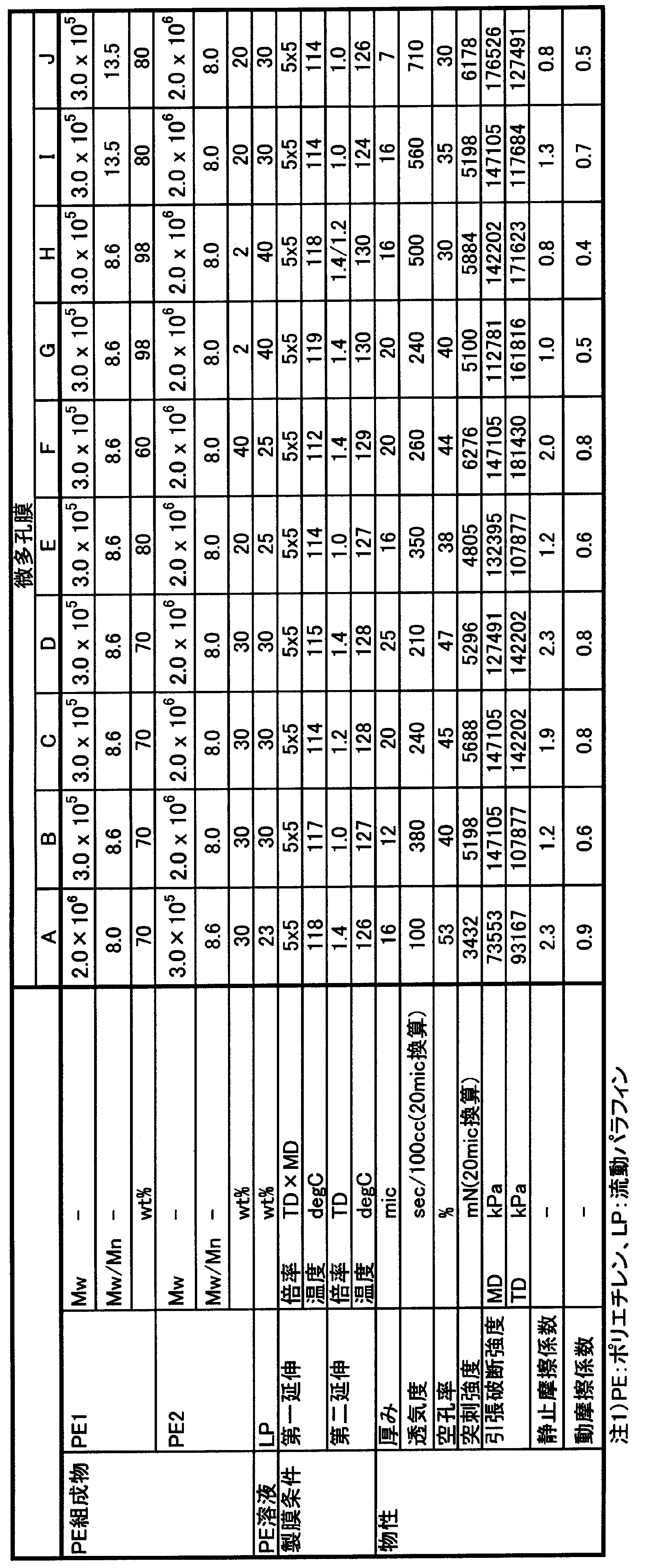
2 巻取部
3 軸受部
4 連結部(スポーク)
5 巻取面
12、13 導電性部材
32 電位計
33 捲回体
34 微多孔膜
35 除電器
100 微多孔膜の第1の面
101 微多孔膜の第1の面の正の静電荷
102 微多孔膜の第1の面の負の静電荷
200 微多孔膜の第2の面
201 微多孔膜の第1の面の正の静電荷
202 微多孔膜の第1の面の負の静電荷
D コア外径
W コア幅
S 微多孔膜
Claims (14)
- 微多孔膜がコアに捲回され、該コアの一部または全部が導電性部材よりなることを特徴とする微多孔膜捲回体。
- 前記微多孔膜の最表面の外周と前記コアの内周の間の静電容量が50pF以上、1000pF以下である、請求項1に記載の微多孔膜捲回体。
- 前記微多孔膜のおもて面と裏面が、互いに逆極性に等量帯電している、請求項1または2に記載の微多孔膜捲回体。
- 長手方向に沿って全長の25%以内の割合で前記おもて面と前記裏面の極性が反転している、請求項3に記載の微多孔膜捲回体。
- 前記おもて面と前記裏面の背面平衡電位が3V以上、150V以下である、請求項3または4に記載の微多孔膜捲回体。
- 前記導電性部材の表面抵抗値が108Ω/□以下である、請求項1~5のいずれかに記載の微多孔膜捲回体。
- 前記導電性部材がコアの巻取面表面に占める面積Aが、微多孔膜とコアとの接触面積Bの50%以上であることを特徴とする請求項1~6のいずれかに記載の微多孔膜捲回体。
- 前記導電性部材の一部または全部が電気絶縁性部材の内部に埋め込まれている、請求項1~7のいずれかに記載の微多孔膜捲回体。
- 前記導電性部材が導電性樹脂からなる、請求項1~8のいずれかに記載の微多孔膜捲回体。
- 前記微多孔膜の静止摩擦係数が0.7以上であり、前記微多孔膜の動摩擦係数が0.3以上である、請求項1~9のいずれかに記載の微多孔膜捲回体。
- 前記微多孔膜の透気度が、膜厚20μm換算で20~800秒/100cm3であり、空孔率が25~80%であり、突刺強度が膜厚20μm換算で1500mN以上である、請求項1~10のいずれかに記載の微多孔膜捲回体。
- 微多孔膜を巻き出した際の表面電位が-5kV~+5kVである、請求項1~11のいずれかに記載の微多孔膜捲回体。
- 前記微多孔膜が電池用セパレータ用途に用いられる、請求項1~12のいずれかに記載の微多孔膜捲回体。
- 微多孔膜がコアに捲回され、該コアの一部または全部が導電性部材よりなる微多孔膜捲回体の製造方法であって、巻取り中の捲回体の表面電位が-2kV~+2kVになるように前記微多孔膜に向けてコロナ放電による除電を行い、前記微多孔膜を巻き取ることを特徴とする微多孔膜捲回体の製造方法。
Priority Applications (5)
| Application Number | Priority Date | Filing Date | Title |
|---|---|---|---|
| KR1020147017134A KR101935081B1 (ko) | 2011-12-07 | 2012-12-06 | 미다공막 권회체 및 그의 제조 방법 |
| EP12856348.3A EP2789560B1 (en) | 2011-12-07 | 2012-12-06 | Microporous membrane roll and method of manufacturing same |
| PL12856348T PL2789560T3 (pl) | 2011-12-07 | 2012-12-06 | Mikroporowata rolka membranowa i sposób jej wytwarzania |
| US14/363,210 US20140322585A1 (en) | 2011-12-07 | 2012-12-06 | Microporous membrane roll and method of manufacturing same |
| CN201280060317.3A CN103974886B (zh) | 2011-12-07 | 2012-12-06 | 微多孔膜卷绕体及其制备方法 |
Applications Claiming Priority (2)
| Application Number | Priority Date | Filing Date | Title |
|---|---|---|---|
| JP2011267661 | 2011-12-07 | ||
| JP2011-267661 | 2011-12-07 |
Publications (1)
| Publication Number | Publication Date |
|---|---|
| WO2013084988A1 true WO2013084988A1 (ja) | 2013-06-13 |
Family
ID=48574343
Family Applications (1)
| Application Number | Title | Priority Date | Filing Date |
|---|---|---|---|
| PCT/JP2012/081636 Ceased WO2013084988A1 (ja) | 2011-12-07 | 2012-12-06 | 微多孔膜捲回体およびその製造方法 |
Country Status (9)
| Country | Link |
|---|---|
| US (1) | US20140322585A1 (ja) |
| EP (1) | EP2789560B1 (ja) |
| JP (1) | JP6149266B2 (ja) |
| KR (1) | KR101935081B1 (ja) |
| CN (1) | CN103974886B (ja) |
| HU (1) | HUE036149T2 (ja) |
| MY (1) | MY169624A (ja) |
| PL (1) | PL2789560T3 (ja) |
| WO (1) | WO2013084988A1 (ja) |
Cited By (5)
| Publication number | Priority date | Publication date | Assignee | Title |
|---|---|---|---|---|
| CN105733017A (zh) * | 2014-12-29 | 2016-07-06 | 东丽电池隔膜株式会社 | 聚烯烃微多孔薄膜的表面处理方法、表面带电装置及聚烯烃微多孔薄膜 |
| JP2016171070A (ja) * | 2015-03-13 | 2016-09-23 | 住友化学株式会社 | セパレータ捲回体、電池の製造方法、及びセパレータ捲回体の製造方法 |
| US20160322622A1 (en) * | 2015-04-30 | 2016-11-03 | Sumitomo Chemical Company, Limited | Separator roll and method of producing same |
| US10115947B2 (en) | 2015-03-13 | 2018-10-30 | Sumitomo Chemical Company, Limited | Separator roll, method for producing battery, and method for producing separator roll |
| WO2020110643A1 (ja) * | 2018-11-30 | 2020-06-04 | 株式会社クラレ | フィルムロール及びその製造方法 |
Families Citing this family (20)
| Publication number | Priority date | Publication date | Assignee | Title |
|---|---|---|---|---|
| JP2017078852A (ja) * | 2015-10-21 | 2017-04-27 | 富士フイルム株式会社 | ドライフィルムレジスト、回路配線の製造方法、回路配線、入力装置および表示装置 |
| JP6105776B1 (ja) | 2016-02-24 | 2017-03-29 | 住友化学株式会社 | コア、セパレータ捲回体、およびセパレータ捲回体の製造方法 |
| KR101807445B1 (ko) | 2016-04-15 | 2017-12-08 | 스미또모 가가꾸 가부시키가이샤 | 다공질 세퍼레이터 장척, 그의 제조 방법, 권회체 및 리튬 이온 전지 |
| JP3206330U (ja) * | 2016-06-30 | 2016-09-08 | 住友化学株式会社 | セパレータ巻芯およびセパレータ捲回体 |
| CN107565080B (zh) * | 2016-06-30 | 2022-06-07 | 住友化学株式会社 | 隔膜卷芯、隔膜卷绕体、以及隔膜卷绕体的制造方法 |
| CN107552493A (zh) * | 2016-06-30 | 2018-01-09 | 住友化学株式会社 | 隔膜卷芯的清洗方法、隔膜卷绕体及其制造方法 |
| KR101895159B1 (ko) | 2016-06-30 | 2018-09-04 | 스미또모 가가꾸 가부시키가이샤 | 세퍼레이터 권취 코어, 세퍼레이터 권회체, 및 세퍼레이터 권회체의 제조 방법 |
| JP3206329U (ja) * | 2016-06-30 | 2016-09-08 | 住友化学株式会社 | セパレータ巻芯、セパレータ捲回体 |
| JP7017853B2 (ja) * | 2016-06-30 | 2022-02-09 | 住友化学株式会社 | セパレータ巻芯の洗浄方法、セパレータ捲回体、およびセパレータ捲回体の製造方法 |
| KR101828741B1 (ko) * | 2016-07-21 | 2018-02-12 | 스미또모 가가꾸 가부시키가이샤 | 세퍼레이터 권취 코어 및 세퍼레이터 권회체 |
| CN107644967B (zh) | 2016-07-21 | 2020-05-05 | 住友化学株式会社 | 间隔件卷芯以及间隔件卷绕体 |
| WO2018025785A1 (ja) * | 2016-08-04 | 2018-02-08 | 帝人株式会社 | 巻芯、電極巻回体の製造装置及び電極巻回体の製造方法 |
| KR101888793B1 (ko) | 2016-08-29 | 2018-08-14 | 스미또모 가가꾸 가부시키가이샤 | 권취 코어, 세퍼레이터 권회체 |
| JP6770855B2 (ja) | 2016-08-31 | 2020-10-21 | 住友化学株式会社 | セパレータ捲回体、セパレータ捲回体の製造方法およびラベル検査方法 |
| US10581051B2 (en) | 2016-12-23 | 2020-03-03 | Sumitomo Chemical Company, Limited | Separator winding core, separator roll, and method of cleaning separator winding core |
| JP6636974B2 (ja) * | 2017-03-02 | 2020-01-29 | 住友化学株式会社 | コア、セパレータ捲回体、およびセパレータ捲回体の製造方法 |
| CN109390637B (zh) * | 2018-11-27 | 2024-08-13 | 深圳市万德自动化科技有限公司 | 一种锂电池电芯离子风除静电下料卷针机构 |
| WO2020163649A1 (en) * | 2019-02-06 | 2020-08-13 | Amtek Research International Llc | Friction enhancing core surface of battery separator roll and related methods |
| JP7533189B2 (ja) * | 2019-12-20 | 2024-08-14 | 東レ株式会社 | ポリオレフィン系微多孔膜、積層体、及びそれを用いた非水電解液二次電池 |
| CN113562535B (zh) * | 2021-07-22 | 2023-01-17 | 明基生物技术(上海)有限公司 | 全自动收丝装置 |
Citations (8)
| Publication number | Priority date | Publication date | Assignee | Title |
|---|---|---|---|---|
| JPS6210298Y2 (ja) * | 1981-07-07 | 1987-03-10 | ||
| JPS63225055A (ja) * | 1987-03-12 | 1988-09-20 | Toray Ind Inc | ポリエステルフイルムロ−ル |
| JPH0739912Y2 (ja) * | 1988-09-07 | 1995-09-13 | 東レ株式会社 | プラスチックフィルム用巻取コア |
| JPH10154501A (ja) * | 1996-11-21 | 1998-06-09 | Nitto Denko Corp | 電池用セパレータ及びこれを用いた非水系2次電池の製造方法 |
| JP2001302820A (ja) | 2000-04-20 | 2001-10-31 | Toray Ind Inc | フィルムロールとその製造方法、および樹脂コア |
| JP2005085556A (ja) * | 2003-09-05 | 2005-03-31 | Sanyo Electric Co Ltd | リチウムイオン電池およびその製造方法 |
| JP2007176034A (ja) | 2005-12-28 | 2007-07-12 | Du Pont Toray Co Ltd | フィルム原反の製造方法およびフィルム原反 |
| WO2011024849A1 (ja) | 2009-08-25 | 2011-03-03 | 旭化成イーマテリアルズ株式会社 | 微多孔膜捲回体及びその製造方法 |
Family Cites Families (18)
| Publication number | Priority date | Publication date | Assignee | Title |
|---|---|---|---|---|
| JPS63160199A (ja) * | 1986-12-23 | 1988-07-02 | 日東電工株式会社 | 静電防止ボビン |
| KR940001366B1 (ko) * | 1991-04-29 | 1994-02-19 | 주식회사 금성사 | 다중 tv의 색신호 화면처리장치 |
| JP3309463B2 (ja) * | 1993-01-21 | 2002-07-29 | 松下電器産業株式会社 | 円筒形ニッケル・水素蓄電池 |
| JP3536391B2 (ja) * | 1994-12-19 | 2004-06-07 | ソニー株式会社 | 巻回電極素子体及びその製造方法並びに巻回電極素子体を用いた電池の製造方法 |
| US6387561B1 (en) * | 1998-10-13 | 2002-05-14 | Ngk Insulators, Ltd. | Electrolyte-solution filling method and battery structure of lithium secondary battery |
| DE10015823A1 (de) * | 2000-03-30 | 2001-10-18 | Epcos Ag | Gehäuster Schichtstapel, Verfahren zur Herstellung des gehäusten Schichtstapels und Verwendung des Verfahrens |
| JP2004022295A (ja) * | 2002-06-14 | 2004-01-22 | Toyota Motor Corp | セパレータおよびその製造方法ならびに蓄電素子 |
| US20040086782A1 (en) * | 2002-11-01 | 2004-05-06 | Celgard Inc. | Explosion-proof separator for Li-ion secondary batteries |
| CA2563787C (en) * | 2004-04-22 | 2013-05-21 | Toray Industries, Inc. | Microporous polypropylene film having a .beta.-crystal activity and a low specific gravity |
| JP4967339B2 (ja) * | 2005-12-28 | 2012-07-04 | 横浜ゴム株式会社 | 空気入りタイヤ |
| KR100896553B1 (ko) * | 2007-04-13 | 2009-05-07 | 엘에스엠트론 주식회사 | 이방성 도전 필름용 릴 |
| US8323821B2 (en) * | 2007-11-09 | 2012-12-04 | Toray Battery Separator Film Co., Ltd. | Multi-layer microporous membrane, battery separator and battery |
| US20100297491A1 (en) * | 2007-11-30 | 2010-11-25 | Takeshi Ishihara | Microporous Polymeric Membrane, Battery Separator, and Battery |
| JP5062783B2 (ja) * | 2008-12-26 | 2012-10-31 | 旭化成イーマテリアルズ株式会社 | ポリオレフィン製微多孔膜 |
| JP5463154B2 (ja) * | 2009-03-19 | 2014-04-09 | 旭化成イーマテリアルズ株式会社 | 積層微多孔膜及び非水電解質二次電池用セパレータ |
| WO2010147149A1 (ja) * | 2009-06-19 | 2010-12-23 | 三菱樹脂株式会社 | 多孔性ポリプロピレンフィルム |
| JP2011014297A (ja) * | 2009-06-30 | 2011-01-20 | Panasonic Corp | 捲回型電極群および電池 |
| JP5232751B2 (ja) * | 2009-09-28 | 2013-07-10 | 日立ビークルエナジー株式会社 | リチウムイオン二次電池 |
-
2012
- 2012-12-06 KR KR1020147017134A patent/KR101935081B1/ko active Active
- 2012-12-06 WO PCT/JP2012/081636 patent/WO2013084988A1/ja not_active Ceased
- 2012-12-06 PL PL12856348T patent/PL2789560T3/pl unknown
- 2012-12-06 US US14/363,210 patent/US20140322585A1/en not_active Abandoned
- 2012-12-06 CN CN201280060317.3A patent/CN103974886B/zh active Active
- 2012-12-06 MY MYPI2014701486A patent/MY169624A/en unknown
- 2012-12-06 HU HUE12856348A patent/HUE036149T2/hu unknown
- 2012-12-06 EP EP12856348.3A patent/EP2789560B1/en active Active
- 2012-12-06 JP JP2012267041A patent/JP6149266B2/ja active Active
Patent Citations (8)
| Publication number | Priority date | Publication date | Assignee | Title |
|---|---|---|---|---|
| JPS6210298Y2 (ja) * | 1981-07-07 | 1987-03-10 | ||
| JPS63225055A (ja) * | 1987-03-12 | 1988-09-20 | Toray Ind Inc | ポリエステルフイルムロ−ル |
| JPH0739912Y2 (ja) * | 1988-09-07 | 1995-09-13 | 東レ株式会社 | プラスチックフィルム用巻取コア |
| JPH10154501A (ja) * | 1996-11-21 | 1998-06-09 | Nitto Denko Corp | 電池用セパレータ及びこれを用いた非水系2次電池の製造方法 |
| JP2001302820A (ja) | 2000-04-20 | 2001-10-31 | Toray Ind Inc | フィルムロールとその製造方法、および樹脂コア |
| JP2005085556A (ja) * | 2003-09-05 | 2005-03-31 | Sanyo Electric Co Ltd | リチウムイオン電池およびその製造方法 |
| JP2007176034A (ja) | 2005-12-28 | 2007-07-12 | Du Pont Toray Co Ltd | フィルム原反の製造方法およびフィルム原反 |
| WO2011024849A1 (ja) | 2009-08-25 | 2011-03-03 | 旭化成イーマテリアルズ株式会社 | 微多孔膜捲回体及びその製造方法 |
Non-Patent Citations (1)
| Title |
|---|
| See also references of EP2789560A4 |
Cited By (9)
| Publication number | Priority date | Publication date | Assignee | Title |
|---|---|---|---|---|
| CN105733017A (zh) * | 2014-12-29 | 2016-07-06 | 东丽电池隔膜株式会社 | 聚烯烃微多孔薄膜的表面处理方法、表面带电装置及聚烯烃微多孔薄膜 |
| JP2016124983A (ja) * | 2014-12-29 | 2016-07-11 | 東レバッテリーセパレータフィルム株式会社 | ポリオレフィン微多孔フィルムの表面処理方法、表面帯電装置及びポリオレフィン微多孔フィルム |
| CN105733017B (zh) * | 2014-12-29 | 2018-11-13 | 东丽株式会社 | 聚烯烃微多孔薄膜的表面处理方法、表面带电装置及聚烯烃微多孔薄膜 |
| JP2016171070A (ja) * | 2015-03-13 | 2016-09-23 | 住友化学株式会社 | セパレータ捲回体、電池の製造方法、及びセパレータ捲回体の製造方法 |
| US10115947B2 (en) | 2015-03-13 | 2018-10-30 | Sumitomo Chemical Company, Limited | Separator roll, method for producing battery, and method for producing separator roll |
| US20160322622A1 (en) * | 2015-04-30 | 2016-11-03 | Sumitomo Chemical Company, Limited | Separator roll and method of producing same |
| US10164234B2 (en) * | 2015-04-30 | 2018-12-25 | Sumitomo Chemical Company, Limited | Separator roll and method of producing same |
| WO2020110643A1 (ja) * | 2018-11-30 | 2020-06-04 | 株式会社クラレ | フィルムロール及びその製造方法 |
| JPWO2020110643A1 (ja) * | 2018-11-30 | 2021-10-14 | 株式会社クラレ | フィルムロール及びその製造方法 |
Also Published As
| Publication number | Publication date |
|---|---|
| CN103974886A (zh) | 2014-08-06 |
| CN103974886B (zh) | 2016-08-17 |
| KR20140102242A (ko) | 2014-08-21 |
| JP6149266B2 (ja) | 2017-06-21 |
| US20140322585A1 (en) | 2014-10-30 |
| MY169624A (en) | 2019-04-23 |
| KR101935081B1 (ko) | 2019-01-03 |
| EP2789560B1 (en) | 2018-01-31 |
| HUE036149T2 (hu) | 2018-06-28 |
| EP2789560A4 (en) | 2015-07-29 |
| EP2789560A1 (en) | 2014-10-15 |
| PL2789560T3 (pl) | 2018-06-29 |
| JP2013139340A (ja) | 2013-07-18 |
Similar Documents
| Publication | Publication Date | Title |
|---|---|---|
| JP6149266B2 (ja) | 微多孔膜捲回体およびその製造方法 | |
| JP6105185B1 (ja) | 積層ポリオレフィン微多孔膜、電池用セパレータおよびそれらの製造方法 | |
| CN102473886B (zh) | 微多孔膜卷绕物及其制造方法 | |
| JP6540806B2 (ja) | 電池用セパレータおよびその製造方法 | |
| JP5914789B1 (ja) | ポリオレフィン微多孔膜、電池用セパレータおよびその製造方法 | |
| JP6555128B2 (ja) | ポリオレフィン微多孔膜、非水電解液系二次電池用セパレータ、ポリオレフィン微多孔膜捲回体、非水電解液系二次電池およびポリオレフィン微多孔膜の製造方法 | |
| JP5914790B1 (ja) | ポリオレフィン微多孔膜、電池用セパレータおよびそれらの製造方法 | |
| KR20160065100A (ko) | 폴리올레핀 다공질 막, 이를 이용한 전지용 세퍼레이터 및 이들의 제조 방법 | |
| WO2013146403A1 (ja) | ポリオレフィン多層微多孔膜 | |
| WO2015190264A1 (ja) | 電池用セパレータ及びその製造方法 | |
| KR20190088567A (ko) | 전지용 세퍼레이터, 전극체 및 비수 전해질 이차전지 | |
| JP6624283B2 (ja) | ポリオレフィン微多孔膜、電池用セパレータおよびこれらの製造方法 | |
| JP2019143008A (ja) | ポリオレフィン微多孔膜 | |
| WO2017169488A1 (ja) | ポリオレフィン微多孔膜、電池用セパレータおよびそれらの製造方法 | |
| JP7375495B2 (ja) | フィルム捲回体のフィルムの伸び量を求める方法 | |
| JP2020164825A (ja) | 微多孔膜、非水電解液二次電池用セパレータ、微多孔膜捲回体及びその製造方法 | |
| WO2019151220A1 (ja) | ポリオレフィン微多孔膜、コーティングフィルム及び電池、並びにポリオレフィン微多孔膜の製造方法 | |
| KR102597797B1 (ko) | 적층체 및 그 제조 방법 | |
| TW201819198A (zh) | 積層聚烯烴微多孔膜、電池用隔膜及其製造方法以及積層聚烯烴微多孔膜捲繞體之製造方法 | |
| JP2024104359A (ja) | ポリオレフィン微多孔膜の製造方法 |
Legal Events
| Date | Code | Title | Description |
|---|---|---|---|
| 121 | Ep: the epo has been informed by wipo that ep was designated in this application |
Ref document number: 12856348 Country of ref document: EP Kind code of ref document: A1 |
|
| WWE | Wipo information: entry into national phase |
Ref document number: 14363210 Country of ref document: US |
|
| NENP | Non-entry into the national phase |
Ref country code: DE |
|
| ENP | Entry into the national phase |
Ref document number: 20147017134 Country of ref document: KR Kind code of ref document: A |
|
| WWE | Wipo information: entry into national phase |
Ref document number: 2012856348 Country of ref document: EP |