WO2013089248A1 - 発電機 - Google Patents
発電機 Download PDFInfo
- Publication number
- WO2013089248A1 WO2013089248A1 PCT/JP2012/082566 JP2012082566W WO2013089248A1 WO 2013089248 A1 WO2013089248 A1 WO 2013089248A1 JP 2012082566 W JP2012082566 W JP 2012082566W WO 2013089248 A1 WO2013089248 A1 WO 2013089248A1
- Authority
- WO
- WIPO (PCT)
- Prior art keywords
- rotor
- stator
- permanent magnet
- protrusions
- side permanent
- Prior art date
- Legal status (The legal status is an assumption and is not a legal conclusion. Google has not performed a legal analysis and makes no representation as to the accuracy of the status listed.)
- Ceased
Links
Images








Classifications
-
- H—ELECTRICITY
- H02—GENERATION; CONVERSION OR DISTRIBUTION OF ELECTRIC POWER
- H02K—DYNAMO-ELECTRIC MACHINES
- H02K1/00—Details of the magnetic circuit
- H02K1/06—Details of the magnetic circuit characterised by the shape, form or construction
- H02K1/22—Rotating parts of the magnetic circuit
- H02K1/27—Rotor cores with permanent magnets
- H02K1/2706—Inner rotors
- H02K1/272—Inner rotors the magnetisation axis of the magnets being perpendicular to the rotor axis
- H02K1/2726—Inner rotors the magnetisation axis of the magnets being perpendicular to the rotor axis the rotor consisting of a single magnet or two or more axially juxtaposed single magnets
- H02K1/2733—Annular magnets
-
- H—ELECTRICITY
- H02—GENERATION; CONVERSION OR DISTRIBUTION OF ELECTRIC POWER
- H02K—DYNAMO-ELECTRIC MACHINES
- H02K21/00—Synchronous motors having permanent magnets; Synchronous generators having permanent magnets
-
- H—ELECTRICITY
- H02—GENERATION; CONVERSION OR DISTRIBUTION OF ELECTRIC POWER
- H02K—DYNAMO-ELECTRIC MACHINES
- H02K21/00—Synchronous motors having permanent magnets; Synchronous generators having permanent magnets
- H02K21/02—Details
- H02K21/021—Means for mechanical adjustment of the excitation flux
- H02K21/028—Means for mechanical adjustment of the excitation flux by modifying the magnetic circuit within the field or the armature, e.g. by using shunts, by adjusting the magnets position, by vectorial combination of field or armature sections
-
- H—ELECTRICITY
- H02—GENERATION; CONVERSION OR DISTRIBUTION OF ELECTRIC POWER
- H02K—DYNAMO-ELECTRIC MACHINES
- H02K21/00—Synchronous motors having permanent magnets; Synchronous generators having permanent magnets
- H02K21/38—Synchronous motors having permanent magnets; Synchronous generators having permanent magnets with rotating flux distributors, and armatures and magnets both stationary
- H02K21/44—Synchronous motors having permanent magnets; Synchronous generators having permanent magnets with rotating flux distributors, and armatures and magnets both stationary with armature windings wound upon the magnets
-
- H—ELECTRICITY
- H02—GENERATION; CONVERSION OR DISTRIBUTION OF ELECTRIC POWER
- H02K—DYNAMO-ELECTRIC MACHINES
- H02K29/00—Motors or generators having non-mechanical commutating devices, e.g. discharge tubes or semiconductor devices
- H02K29/03—Motors or generators having non-mechanical commutating devices, e.g. discharge tubes or semiconductor devices with a magnetic circuit specially adapted for avoiding torque ripples or self-starting problems
Definitions
- the present invention relates to a generator.
- the power generation efficiency of the generator can be improved as the number of turns of the coil increases. However, when the number of turns of the coil is increased, the generator is increased in size.
- Patent Document 1 discloses a motor in which a rotor-side magnet and a stator-side coil are arranged in a predetermined positional relationship to reduce the size and improve the output. Therefore, it is considered that a generator with high power generation efficiency can be obtained by adopting the positional relationship between the magnet and coil of the motor in the generator.
- Patent Document 2 discloses means for suppressing the cogging by making the shape of the portion to which the magnet of the rotor is attached have a predetermined shape, so that the change in magnetic flux when the rotor rotates is moderated. ing.
- JP 2006-340425 A see abstract, etc.
- JP 2006-101695 A see abstract, etc.
- an object of the present invention is to provide a power generator that can sufficiently suppress cogging without having a complicated structure.
- the generator according to the present invention is made of a soft magnetic material, and includes a rotor yoke having a cylindrical nonmagnetic material portion and a multiple of 2 grooves toward the nonmagnetic material portion, and NS magnetizing in the axial direction.
- Ring-shaped rotor-side permanent magnets and a plurality of rotors that protrude toward the stator side of the rotor-side permanent magnets and that are arranged at a fixed pitch in a straight line at positions spaced apart from each other across the rotor-side permanent magnets
- a rotor portion comprising a side protrusion, a soft magnetic material, a stator yoke, a ring-shaped stator side permanent magnet opposed to the rotor side permanent magnet and oppositely magnetized in the axial direction, and a stator side permanent magnet And a stator side projecting portion arranged in a straight line at a constant pitch at positions spaced apart from each other across the stator side permanent magnet, and a stator side between adjacent stator members.
- Protrusion There are those having a stator part which is to be shifted half a pitch from each other.
- a non-magnetic body portion is installed in a multiple, and each non-magnetic body portion extends in the axial direction so as to connect two adjacent rotor-side permanent magnets, and the length of the non-magnetic body portions corresponds to the two rotors. It is preferable that the distance between the outer ends in the axial direction of the side permanent magnet is not less than the distance.
- Another generator of the present invention is made of a soft magnetic material, and includes a rotor non-magnetic material portion and a multiple of two grooves toward the non-magnetic material portion, and a rotor yoke disposed in each groove and axially Ring-shaped rotor-side permanent magnets which are magnetized in NS, and a plurality of rotor-side projecting portions which protrude toward the stator side with respect to the rotor-side permanent magnets and are spaced apart from each other across the rotor-side permanent magnets
- the rotor-side protruding portion disposed between the two rotor-side permanent magnets includes a rotor-side protruding portion that is shifted by a half pitch from each other at a position that bisects the axial length thereof.
- stator yoke a ring-shaped stator-side permanent magnet opposed to the rotor-side permanent magnet and oppositely magnetized in the axial direction, and projecting to the rotor portion side of the stator-side permanent magnet.
- stator side protrusions arranged in a straight line at a constant pitch at positions separated from each other are arranged so that the stator side protrusions are arranged in a straight line at a constant pitch between adjacent stator members.
- stator portion a stator portion.
- the nonmagnetic body portions are installed in multiples, and each nonmagnetic body portion extends in the axial direction so as to connect two adjacent rotor-side permanent magnets, and its length. Is preferably equal to or greater than the distance between both outer ends in the axial direction of the rotor-side permanent magnets.
- the area of the portion where the rotor side protruding portion and the stator side protruding portion face each other and the area of the portion which does not face each other are constant regardless of the positional relationship in the rotational direction between the rotor portion and the stator portion. It is preferably set.
- Still another generator according to the present invention may be configured to have a non-magnetic part instead of the stator-side permanent magnet.
- a generator capable of sufficiently suppressing cogging without having a complicated structure can be realized.
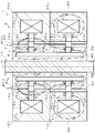
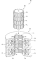
- FIG. 2 is a partially cutaway perspective view showing a configuration of a stator portion of the generator of FIG. 1, and also shows a rotor portion and its insertion direction.
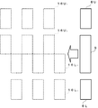
- FIG. 2 is a partially cutaway perspective view showing a configuration of a rotor portion of the generator of FIG. 1. It is a figure which shows the positional relationship of the circumferential direction (rotation direction) of the rotor side protrusion part (solid line) of the rotor part of FIG. 1, and the stator side protrusion part (broken line) of the stator part of FIG.
- FIG. 8 is a diagram schematically showing the state of the magnetic path in the generator in the state S2 in the predetermined positional relationship in FIG.
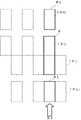
- FIG. 7 is cut along the line AA in FIG. It is a figure which shows state S3 which is the predetermined positional relationship of the rotor side protrusion part (solid line) of the rotor part of FIG. 1, and the stator side protrusion part (broken line) of the stator part of FIG. It is a figure which shows typically the state of the magnetic path in a generator in state S3 which is the predetermined positional relationship of FIG.
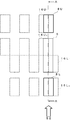
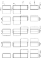
- FIG. 3 is a diagram showing a change in positional relationship with the passage of time (time t1 to t5) between a rotor-side protruding portion (solid line) of the rotor portion of FIG. 1 and a stator-side protruding portion (broken line) of the stator portion of FIG. FIG.
- FIG. 12 is a diagram schematically showing a current generation state in two winding portions in the generator over time (time t1 to t5) in FIG. It is a figure which shows typically the state of the magnetic path in a generator in case a bypass part is provided in the yoke by the side of a rotor part as a comparative example. It is a partially notched perspective view which shows the structure of the rotor part and stator part of the generator of other embodiment. It is a figure which shows the principal part of the generator of other embodiment by the cross section containing the central axis of a rotor part.
- the magnetic flux is a bundle of magnetic lines of force
- the magnetic path is a path of magnetic lines of force.
- the expression that a magnetic path is formed by magnetic flux may be replaced when a magnetic path is formed by magnetic lines of force.
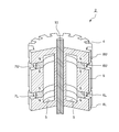
- the generator 1 has a rotor portion 2 and a stator portion 3 as shown in FIGS.
- the rotor unit 2 includes a rotor yoke 4 made of a cylindrical soft magnetic material.
- a cylindrical hollow portion 5 having a square cross section and two grooves 6U and 6L provided in the circumferential direction are provided from the outer peripheral surface a of the rotor yoke 4 to the hollow portion 5 serving as a nonmagnetic material portion. And are provided.
- a ring-shaped permanent magnet 7U is provided so as to be sandwiched between the wall surfaces of the groove 6U, and a ring-shaped permanent magnet 7L is also provided so as to be sandwiched between the wall surfaces of the groove 6L.
- the rotor yoke 4 has a plurality of rectangular parallelepiped protrusions 8U made of a magnetic material on the upper side in the axial direction of the permanent magnet 7U in FIGS. 1 to 3, and the lower side of the permanent magnet 7L in the axial direction in FIGS.
- a plurality of rectangular parallelepiped protrusions 8L made of a magnetic material are provided, and a plurality of rectangular parallelepiped protrusions 9 made of a magnetic material are provided between the permanent magnets 7U and 7L.
- the outer peripheral surfaces of the protrusions 8U, 9, 8L are the outer peripheral surface a of the rotor yoke 4.
- the protrusions 8U, 9, 8L are arranged so as to be equiangularly spaced with respect to the central axis C of the rotor yoke 4 and to be linear in the axial direction.
- each projecting portion 8U, 9, 8L has an arcuate cross section, and if the length of one outer peripheral surface a is L, the virtual outer peripheral surface of the adjacent projecting portions 8U, 9, 8L The distance on a is also L.
- a rotation shaft 10 is provided at the center of the rotor yoke 4. The portions where the rotor yoke 4 and the rotating shaft 10 are in contact are joined together, and the rotor yoke 4 also rotates as the rotating shaft 10 rotates.
- FIGS. 1 to 3 are omitted illustration of the housing of the generator 1, the housing, the protrusion 8U rotor portion 2, 9,8L and protrusions 16U 1 of the stator portion 3, which will be described later, 16U
- the rotor part 2 and the stator part 3 are accommodated so that 2 , 16L 1 and 16L 2 maintain a slight gap.
- the rotating shaft 10 protrudes directly from the casing or indirectly through a toothed wheel train, and when the rotating torque is applied to the rotating shaft 10 from the outside, the rotor portion 2 It rotates with the rotating shaft 10 inside the part 3.
- the protrusions 8U, 9, and 8L are manufactured by integral molding with the main body of the rotor yoke 4, and the protrusions 16U 1 , 16U 2 , 16L 1 , and 16L 2 described later are also integrally molded with the stator yokes 12U and 12L, respectively. It is manufactured.
- the rotor unit 2 has an upper end surface of the upper permanent magnet 7U having an N pole, a lower end surface having an S pole, and an upper end surface of the lower permanent magnet 7L having an S pole. Yes, and the lower end surface is an N pole. That is, the ring-shaped permanent magnets 7U and 7L are both subjected to NS magnetization in the axial direction, and are arranged so that the surfaces of the two permanent magnets 7U and 7L facing each other have the same polarity.
- the magnetic flux of the upper permanent magnet 7U flows from the lower end of the protruding part 8U through the outside of the rotor part 2 to the upper end of FIG. 1 of the protruding part 9, and returns to the S pole.
- the magnetic flux of the lower permanent magnet 7L flows from the upper end of the projecting portion 8L through the outside of the rotor portion 2 to the lower end in FIG. 1 of the projecting portion 9 and returns to the S pole.
- the magnetic flux is always radiated and incident from the protruding portions 8U, 9, 8L.
- the density of magnetic flux can be increased and the attractive force can be increased.
- the stator portion 3 has a two-stage stacked structure in which stator yokes 12U and 12L made of a cylindrical soft magnetic body having a columnar hole 11 for inserting the rotor portion 2 at the center are stacked in the axial direction. It has become.
- the stator yokes 12U and 12L are described as “two-layered structure”. However, in practice, a portion corresponding to the stator yoke 12U and the stator yoke 12L are connected to one yoke member. Corresponding portions may be formed, or two stator yokes 12U and stator yokes 12L formed separately may be actually joined in two stages.
- stator yokes 12U and 12L of the stator part 3 ring-shaped hollow parts 13U and 13L each having a square cross section, and through the inner peripheral surface (hole 11 side) of the stator yokes 12U and 12L to the hollow parts 13U and 13L
- ring-shaped grooves 14U and 14L provided in the circumferential direction are provided.
- a ring-shaped permanent magnet 15U is mounted in the groove 14U of the stator yoke 12U
- a ring-shaped permanent magnet 15L is mounted in the groove 14L of the stator yoke 12L.
- each protrusion 16U 1 , 16U 2 , 16L 1 , 16L 2 is opposed to the outer peripheral surface a of the rotor yoke 4, and each radial length thereof is the length L of each outer peripheral surface a. Further, it is configured to be slightly smaller.
- the protrusions 16U 1 and 16U 2 of the stator yoke 12U and the protrusions 16L 1 and 16L 2 of the stator yoke 12L are arranged so as to be shifted from each other by a half pitch in the circumferential direction with respect to the central axis of the stator yokes 12U and 12L. Yes.
- protrusions 16U 1 , 16U 2 , 16L 1 , 16L 2 are equiangularly spaced with respect to the central axes of the stator yokes 12U, 12L in the circumferential direction along the inner side surfaces of the stator yokes 12U, 12L, and each protrusion 16U 1, 16U 2, 16L 1 , 16L protrusions 16U 1 adjacent to have a spacing of width length and the same length of the inner circumferential surface b of 2, 16U 2, 16L 1, 16L 2 is formed Is arranged to be. Furthermore, in the hollow portions 13U and 13L, winding portions 17U and 17L around which wires are wound in the circumferential direction are provided, respectively.
- the winding portion 17U has multiple wires wound in the circumferential direction, and both ends (not shown) are drawn outward from the stator yoke 12U.
- the winding portion 17L is wound with multiple wires, and both ends (not shown) are drawn outward from the stator yoke 12L.
- the current generated in the generator 1 is led out from each wire.
- the upper end surface of the permanent magnet 15U of the stator yoke 12U is an S pole, and the lower end surface is an N pole.
- the stator yoke 12U usually passes from the N pole on the lower end surface of the permanent magnet 15U through the inner peripheral surface and the inside of the stator yoke 12U. Bent from the vicinity of the boundary between the stator yoke 12U and the stator yoke 12L, bent outward from the center of the stator yoke 12U, bent at a position on the outer peripheral side, along the outer peripheral surface, and inside the outer peripheral side.
- the lower end surface of the permanent magnet 15L of the stator yoke 12L is the S pole and the upper end surface is the N pole.
- the stator yoke 12L normally passes from the N pole on the upper end surface of the permanent magnet 15L through the inner peripheral surface and the inside of the stator yoke 12L.
- a part of the magnetic flux is emitted from the stator yoke 12L near the N pole of the permanent magnet 15L to the hole 11 side and forms a magnetic path that returns to the stator yoke 12L near the S pole of the permanent magnet 15L.
- the protruding portions 16U 1 and 16U 2 of the stator portion 3 shown in FIG. 1 do not face the protruding portions 8U and 9 of the rotor portion 2.
- the protruding portions 16L 1 and 16L 2 of the stator portion 3 shown in FIG. 1 are opposed to the protruding portions 9 and 8L of the rotor portion 2.
- the rotor portion 2 protrusion 8U, 9,8L, when you are completely opposed to the protrusion 16L 1, 16L 2 of the stator yoke 12L is protruded portion 16U 1 of the stator yoke 12U, There will be no state facing 16U 2 at all.
- the generator 1 rotates the rotor yoke 4 of the rotor portion 2 with the rotation of the rotary shaft 10, so that the protruding portions 8 U, 9, 8 L of the rotor portion 2 become the protruding portions 16 U of the stator portion 3. 1 , 16 U 2 , 16 L 1 , 16 L 2 passing through the circumferential direction. Due to the change in magnetic flux generated at this time, current flows through the winding portions 17U and 17L of the stator portion 3 to generate power. By appropriately taking out the current flowing through the winding portions 17U and 17L, the generator 1 can store electricity or drive a load.
- the protrusions 16U 1 , 16U 2 of the stator part 3 are not opposed to any of the protrusions 8U, 9, 8L of the rotor part 2, and are below the protrusions 9 of the rotor part 2.
- the protruding portion 8L of the rotor portion 2 and the state is opposed to the protrusion 16L 2 of the stator portion 3 S1.
- stator yoke 12U of the stator portion 3 is not significantly affected by the attractive force of the projecting portions 8U and 9 of the rotor portion 2, and thus the permanent magnet of the stator yoke 12U.
- Many magnetic fluxes of 15U form a magnetic path M1 (shown by a one-dot chain line) that returns from the N pole of the permanent magnet 15U to the S pole of the permanent magnet 15U through the periphery of the hollow portion 13U.
- the magnetic flux of the permanent magnet 7L of the rotor portion 2 is reduced. Most of the magnetic flux of the permanent magnet 15L of the stator portion 3 flows into the rotor portion 2 while almost flowing into the stator yoke 12L side from the protruding portions 9 and 8L of the rotor portion 2.
- the hollow part 5 circulates from the vicinity of the upper end part of the rotor yoke 4 from the N pole on the upper end surface of the permanent magnet 7 ⁇ / b> U, and the stator yoke 12 ⁇ / b> L side near the lower end part of the rotor yoke 4. Is formed, and a magnetic path M2 is formed near the upper end portion of the stator yoke 12L and again enters the rotor portion 2 side and returns to the S pole on the lower end surface of the permanent magnet 7U.
- the air flows into the rotor portion 2 and is radiated from the protruding portion 16U 2 of the stator portion 3 to the rotor portion 2 side.
- most of the magnetic flux of the permanent magnet 7U of the rotor part 2 flows into the stator part 3 side. That is, it flows into the stator portion 3 side from the protruding portion 8U on the rotor portion 2 side.
- the N pole of the permanent magnet 7U on the rotor part 2 side is directed to the S pole of the permanent magnet 15U on the stator part 3 side, and the N pole of the permanent magnet 15U on the stator part 3 side is changed to the permanent magnet 7U on the rotor part 2 side.
- a magnetic path M4 toward the S pole is formed. Along with this, the magnetic flux of the magnetic path M5 passing around the winding portion 17U is weakened compared to the magnetic path M1 in the state S1 (S1: thick one-dot chain line ⁇ S2: illustrated as a thin one-dot chain line).
- a part of the magnetic flux of the permanent magnet 7L of the rotor part 2 radiated to the stator yoke 12L side of the stator part 3 in the state S1 returns to the rotor part 2 side via the hollow part 5. Further, part of the magnetic flux of the permanent magnet 15L of the stator portion 3 also passes around the winding portion 17L. That is, compared with the state S1, the N magnetic pole of the permanent magnet 15L on the stator portion 3 side is directed from the N pole of the permanent magnet 7L on the rotor portion 2 side to the S pole of the permanent magnet 15L on the stator portion 3 side by weak magnetic lines of force. A magnetic path M6 is formed from the permanent magnet 7L toward the south pole of the rotor portion 2 side.
- the magnetic flux of the magnetic path M7 passing around the winding portion 17L is strengthened as compared with the state S1 (S1: no alternate long and short dashed line ⁇ S2: illustrated as a thin alternate long and short dashed line).
- S1 no alternate long and short dashed line
- ⁇ S2 illustrated as a thin alternate long and short dashed line.
- the magnetic path M2 is generated in the rotor portion 2 facing the projecting portions 16L 1 and 16L 2 of the stator portion 3, but its strength is weakened.
- a magnetic path M9 described later is generated, its strength is in the middle of gradually increasing.
- the protrusions 16L 1 , 16L 2 of the stator part 3 are not opposed to any of the protrusions 8U, 9, 8L of the rotor part 2, and the upper part of the protrusion part 9 of the rotor part 2 half facing the protrusion 16U 2 of the stator portion 3, the protrusion 8U of the rotor portion 2 and the state is opposed to the protrusion 16U 1 of the stator portion 3 S3.
- the magnetic flux of the permanent magnet 7L of the rotor portion 2 is more strongly affected by the protrusions 16U 1 and 16U 2 of the stator yoke 12U than the protrusions 16L 1 and 16L 2 of the stator yoke 12L of the stator portion 3. Most of the magnetic flux of the rotor part 2 is radiated to the stator yoke 12U side. Further, since the protrusions 16U 1 and 16U 2 of the stator part 3 and the protrusions 8U and 9 of the rotor part 2 are very close to each other, the magnetic flux of the permanent magnet 7U of the rotor part 2 is transferred from the protrusion part 8U of the rotor part 2 to the stator.
- the hollow portion 5 circulates from the vicinity of the lower end portion of the rotor yoke 4 from the N pole on the lower end surface of the permanent magnet 7L, and the stator yoke 12U side in the vicinity of the upper end portion of the rotor yoke 4 Is formed, and the magnetic path M9 is formed near the lower end portion of the stator yoke 12U and again enters the rotor portion 2 side and returns to the S pole on the upper end surface of the permanent magnet 7L.
- the magnetic flux of the permanent magnet 15U of the stator yoke 12U of the stator portion 3 flows into the protruding portion 9 of the rotor portion 2, and the magnetic flux of the permanent magnet 7U of the rotor portion 2 is changed from the protruding portion 8U of the rotor portion 2 to the stator portion 3.
- a magnetic path M10 that flows into the protrusion 16U 1 is formed.
- FIG. 11 shows the positional relationship between the protrusions 8U, 9, 8L of the rotor portion 2 and the protrusions 16U 1 , 16U 2 , 16L 1 , 16L 2 of the stator portion 3, and the above-described states S1, S2, S3 are S1 ⁇ The process of transition from S2 to S3 is shown along with the elapse of time t1 to t5.
- FIG. 12 shows the state of current generated in the winding portions 17U and 17L of the generator 1 at the respective times t1 to t5 shown in FIG. As shown in FIG. 12, when the rotor unit 2 rotates at a constant rotational speed, sinusoidal current waveforms are generated in the winding units 17U and 17L.
- FIG. 12 shows the example of FIG.
- time t1 corresponds to state S1 shown in FIG.
- the lower half of the protruding portion 9 of the rotor portion 2 and the protruding portion 8L and the protruding portions 16L 1 and 16L 2 of the stator portion 3 face each other, and the magnetic flux around the winding portion 17U becomes maximum, and then decreases. Therefore, a current that generates magnetic field lines in a direction that prevents the change starts to flow in a certain direction through the wire. If this direction is positive, positive current starts to flow. This point is shown as W11 in FIG. On the other hand, since the magnetic flux around the winding portion 17L is minimized and then increases, a current that generates magnetic lines in a direction that prevents the change flows through the wire.
- the flowing direction is opposite to the winding portion 17U. This direction is negative with respect to the above-mentioned positive. This point is shown as W21 in FIG. At this time, the lower portion of the rotor portion 2 generates the maximum suction force with the stator portion 3.
- the time t5 corresponds to the state S3 shown in FIG.
- the upper half of the protruding portion 9 of the rotor portion 2 and the protruding portion 8U and the protruding portions 16U 1 and 16U 2 of the stator portion 3 face each other , and the magnetic flux around the winding portion 17L becomes maximum, and then decreases. Therefore, a current that generates magnetic field lines in a direction that prevents the change starts to flow in a certain direction through the wire. This direction is negative according to the above criteria. This point is shown as W12 in FIG.
- Time t3 corresponds to state S2 shown in FIG.
- the circumferential half of the protrusions 8U, 9, and 8L of the rotor portion 2 and the circumferential half of the protrusions 16U 1 , 16U 2 , 16L 1 , and 16L 2 of the stator portion 3 face each other.
- Times t2 and t4 are processes of transition from state S1 to S2 and from S2 to S3, respectively. Therefore, at time t2, as shown in FIG. 12, a current having an intermediate value between the current value (0 amperes) generated in state S1 and the current value generated in state S2 is generated in winding parts 17U and 17L. To do. At time t4, as shown in FIG. 12, currents having intermediate values between the current value generated in state S2 and the current value (maximum value) generated in state S3 are generated in winding portions 17U and 17L, respectively. To do.
- the cause is that the attractive force or the repulsive force between the rotor side and the stator side changes depending on the position of the rotor.
- the protrusions 8U, 9, 8L of the rotor part 2 and the protrusions of the stator part 3 are in any positional relationship between the rotor part 2 and the stator part 3 at any time t1 to t5.
- the suction force between 16U 1 , 16U 2 , 16L 1 and 16L 2 is always constant.
- the lower half of the projecting portion 9 of the rotor portion 2 and the projecting portion 8L and the projecting portions 16L 1 and 16L 2 of the stator portion 3 face each other with the maximum suction force. I am inquiring.
- the protrusions 16U 1 and 16U 2 of the stator part 3 are not opposed to any of the protrusions 8U, 9 and 8L of the rotor part 2, and the mutual attractive force is minimum.
- the strength of the suction force between the protrusions 8U, 9, 8L on the rotor part 2 side and the protrusions 16U 1 , 16U 2 , 16L 1 , 16L 2 on the stator part 3 side is Considering that it depends on the sum of the strength of the opposing area portion and the strength of the non-opposing area portion between the protruding portions 8U, 9, 8L and the protruding portions 16U 1 , 16U 2 , 16L 1 , 16L 2 on the stator 3 side. Can do.
- protrusions 16U 1 of the stator portion 3, 16U 2, 16L 1, or 16L 2 are protrusions 8U rotor portion 2, the maximum value of the area at the time of facing the 9,8L and Qcm 2 (square centimeter), 1 cm 2
- the facing area between the lower half of the protrusion 9 of the rotor portion 2 and the protrusion 16L 1 of the stator portion 3 is Qcm 2 and the suction force is Q at time t1.
- Qcm 2 attraction opposing area between the projecting portions 16L 2 of the protruding portion 8L and the stator portion 3 of the rotor portion 2 becomes Q ⁇ P1.
- a quarter in the circumferential direction of the protruding portion 8U of the rotor portion 2 and a quarter in the circumferential direction of the protruding portion 16U 1 of the stator portion 3 face each other, and the rotor portion 2 A quarter in the circumferential direction of the upper half of the projecting portion 9 and a quarter in the circumferential direction of the projecting portion 16U 2 of the stator portion 3 are opposed to each other in the circumferential direction of the lower half of the projecting portion 9 of the rotor portion 2.
- a half in the circumferential direction of the protruding portion 8U of the rotor portion 2 and a half in the circumferential direction of the protruding portion 16U 1 of the stator portion 3 face each other, and the rotor portion 2 A half in the circumferential direction of the upper half of the protruding portion 9 and a half in the circumferential direction of the protruding portion 16U 2 of the stator portion 3 are opposed to each other in the circumferential direction of the lower half of the protruding portion 9 of the rotor portion 2.
- the projecting portion 16L 1 of the stator portion 3 and the facing areas between the projecting portion 8L of the rotor portion 2 and the projecting portion 16L 2 of the stator portion 3 are (1/2) Qcm 2 , respectively.
- the suction force of the non-opposing portion that is, the portion where the protrusions 16U 1 , 16U 2 , 16L 1 , 16L 2 of the stator 3 are not opposed to the protrusions 8U, 9, 8L of the rotor 2 Since its area is 2Qcm 2 , 2Qcm 2 ⁇ P2. Therefore, the total sum of the attractive forces at time t3 is 2Q (P1 + P2), similar to times t1 and t2.
- a quarter of the protrusion 8U of the rotor portion 2 3 and 4 minutes in the upper half of the protrusion 9 of the stator section three quarters of protrusions 16U 1 of 3 and the rotor part 2 3 and the stators 3
- the opposing areas between the projecting portions 16U 2 and three-quarters are (3/4) Qcm 2 , respectively, the lower half of the projecting portion 9 of the rotor portion 2 and the projecting portion of the stator portion 3
- the opposing areas between 1/4 of 16L 1 and 1/4 of the protrusion 8L of the rotor part 2 and 1/4 of the protrusion 16L2 of the stator part 3 are (1/4) Qcm 2 , respectively. is there.
- the area of the portion where the protrusions 8U, 9 and 8L of the rotor part 2 are opposed to the protrusions 16U 1 , 16U 2 , 16L 1 and 16L 2 of the stator part 3 is 2Qcm 2 , and the overall suction force is It is “2Q (P1 + P2)”, similar to the times t1, t2, and t3.
- the upper half of the protruding portion 9 of the rotor portion 2 and the protruding portion 8U and the protruding portions 16U 1 and 16U 2 of the stator portion 3 face each other and strongly attract each other.
- the protrusions 16L 1 and 16L 2 of the stator part 3 are not opposed to any of the protrusions 8U, 9 and 8L of the rotor part 2.
- the opposing area between the upper half of the protrusion 9 of the rotor 2 and the protrusion 16U 2 of the stator 3 and between the protrusion 8U of the rotor 2 and the protrusion 16U 1 of the stator 3 is Qcm 2. It is.
- the area of the portion where the protrusions 8U, 9 and 8L of the rotor part 2 are opposed to the protrusions 16U 1 , 16U 2 , 16L 1 and 16L 2 of the stator part 3 is 2Qcm 2 , and the overall suction force is Like time t1, t2, t3, t4, “2Q (P1 + P2)” is obtained.
- the current waveform generated at times t1 to t5 is a current waveform corresponding to one quarter of the sinusoidal current waveforms generated in the winding portions 17U and 17L.
- the sine wave is a quarter of this current waveform.
- the current waveform for a period is continuous while changing the increase / decrease direction and the positive / negative direction.
- the hollow part 5 of the rotor part 2 is connected over the two permanent magnets 7U and 7L.
- the magnetic fluxes of the two permanent magnets 7U and 7L of the rotor portion 2 are not divided, so that one magnetic path M2 or M9 is formed and integrated. Is incident on the stator portion 3, so that the magnetic flux passing through the winding portion 17U or the winding portion 17L is almost completely eliminated, and on the side not incident on the stator portion 3, the incidence is almost eliminated and the winding portion 17U or the winding portion.
- the magnetic flux passing around 17L can be made as close as possible. As a result, the power generation efficiency can be further increased.
- FIG. 13 shows a rotor portion 2A having two hollow portions 5U and 5L as a comparative example.
- FIG. 13 shows an example of the state S1 as in FIG. 6, but in the comparative example shown in FIG. 13, the loop by the magnetic flux of the permanent magnet 7U and the loop by the magnetic flux of the permanent magnet 7L of the rotor portion 2A are separated from each other. Magnetic paths M11 and M12, which are closed loops, are formed. Accordingly, a magnetic path M13 is generated around the winding part 17U, and a magnetic path M14 is generated around the winding part 17L. This hardly changes in any state from time t1 to time t5 shown in FIG.
- the hollow portion 5 may not be hollow and may be configured to embed a non-magnetic material such as aluminum or a resin material.
- each protrusion 8U, 9,8L is body and integrally molded of the yoke 4, each of the protrusions 16U 1, 16U 2, 16L 1 , 16L 2 yoke 12U, has been described as being integrally molded and 12L, Each projecting portion may not be integrally molded, but may be fixed to each main body by bonding or the like as a separate member.
- the rotor portion 2B has four protruding portions 8U 1 , 8U 2 , 8L 1 , 8L 2 in the axial direction.
- the protruding portions 8U 1 , 8U 2 and the protruding portions 8L 1 , 8L 2 are arranged so as to be shifted from each other by a half pitch in the axial direction.
- the stator portion 3B has three projecting portions 16U, 16M, and 16L having the same pitch in the axial direction. Even if such a generator 1B is configured, the generator 1B having the same function as the generator 1 in the above-described embodiment can be realized.
- the rotor portion 2B includes a rotor member having protrusions 8U 1 and 8U 2 having the same pitch in the central axis direction, and a rotor having protrusions 8L 1 and 8L 2 having a straight line in the central axis direction and the same pitch.
- the members can be configured by overlapping the protrusions 8U 1 , 8U 2 and the protrusions 8L 1 , 8L 2 in two stages so as to be shifted from each other by a half pitch.
- stator portion 3B is also straight in the central axis direction, and is a straight line in the central axis direction with the stator member having the protruding portions 16U and 16M 1 having the same pitch, and the protruding portion 16M 2 having the same pitch.
- the rotor member having the portion 16L can be configured by arranging the protruding portions 16U, 16M 1 , 16M 2 , and 16L in a straight line and overlapping each other in two steps.
- the generators 1 and 1B have been described as having the stator portion 3 composed of the stator yokes 12U and 12L having a two-stage stack structure, the number of stages to be stacked may be any number as long as it is an even number. In this case, it is preferable that the rotor portion 2 has a structure in which those shown in FIG. 14 are stacked in the axial direction.
- the generator 1B has been described as having the rotor part 2B made of a rotor member having a two-stage stack structure. However, it is preferable to stack the rotor parts 2B having the same structure, and the number of stages to be stacked is an even number. Any number of stages may be used.
- the generators 1 and 1B described above are of the inner rotor type, but may be of the outer rotor type.
- the rotor yoke 4 and the stator yokes 12U and 12L are preferably soft magnetic materials, but may be simple magnetic materials.
- the grooves 6U, 6L, 14U, and 14L are not formed when they are integrally formed with the permanent magnet, but are referred to as grooves including the case of such integral formation.
- the hollow portion 5 serving as the non-magnetic body portion has an axial length that is longer than the distance between the axial outer ends of the permanent magnet 7U and the permanent magnet 7L, but the distance between the axial outer ends. It may be the same, slightly longer, or slightly shorter. In order to make cogging zero, it is preferable that the width of the protruding portion and the width between the protruding portions are the same, but the widths of both may not be the same and may be slightly different due to other requirements.
- a generator 1 ⁇ / b> C including the stator yoke 3 ⁇ / b> CU and 12 ⁇ / b> CL that do not have the permanent magnets 15 ⁇ / b> U and 15 ⁇ / b> L can be configured in the stator portion 3 ⁇ / b> C. That is, the generator 1C uses the space after removing the permanent magnets 15U, 15L from the stator portion 3 of the generator 1 as a non-magnetic body portion. Note that the space after the permanent magnets 15U and 15L are removed from the stator portion 3 may be filled with a resin or aluminum which is a non-magnetic material.
- the generator 1C operates in the same manner as the generators 1 and 1B according to the above-described embodiment. However, since the stator 3C does not have the permanent magnets 15U and 15L, the current waveform shown in FIG. Inverted at the portions 17U and 17L.
- the state shown in FIG. 15 corresponds to the state S1 shown in FIG.
- the state of the generator 1 in the state S1 shown in FIG. 6 since the generator 1 has the permanent magnet 15L in the stator yoke 12L, the magnetic flux of the permanent magnet 15L is attracted to the rotor portion 2 side. Therefore, the magnetic flux around the winding portion 17L becomes weak.
- the generator 1C since there is no permanent magnet 15L in the stator yoke 12CL, the protrusions 9 and 8L and the protrusions 16L 1 and 16L 2 are opposed to each other by the magnetic flux of the permanent magnet 7L of the rotor portion 2. To enter the stator yoke 12CL side. Thereby, the magnetic path M15 is formed and the magnetic flux around the winding portion 17L becomes strong.
- the stator yoke 12U since the stator yoke 12U includes the permanent magnet 15U, in the state S1, the magnetic path M1 is formed around the winding portion 17U by the magnetic flux of the permanent magnet 15U, and thus the winding portion 17U. The magnetic flux around is strong.
- the stator yoke 12CU since the stator yoke 12CU does not have the permanent magnet 15U, the magnetic flux of the permanent magnet 7U of the rotor part 2 enters the stator yoke 12CU side to form the magnetic path M16, but the stator part 3C side Since the protruding portions 16U 1 and 16U 2 are not opposed to the protruding portions 8U and 9 of the rotor portion 2, the magnetic flux around the winding portion 17U becomes weak.
Landscapes
- Engineering & Computer Science (AREA)
- Power Engineering (AREA)
- Permanent Magnet Type Synchronous Machine (AREA)
- Permanent Field Magnets Of Synchronous Machinery (AREA)
- Iron Core Of Rotating Electric Machines (AREA)
Abstract
複雑な構造となることなく、また、コギングの抑制も十分に図られる発電機を提供すること。 永久磁石7U,7Lをはさんで互いに離れた位置に一直線状で定ピッチにて配置される複数の突出部8U,9,8Lと、からなるロータ部2と、ステータヨーク12U,12Lと、永久磁石7U,7Lと対向する永久磁石15U,15Lと、永久磁石15U,15Lよりもロータ部2側に突出し、永久磁石15U,15Lをはさんで互いに離れた位置に一直線状で定ピッチにて配置される突出部16U1,16U2,16L1,16L2と、からなるステータ部材を、隣接するステータ部材間で突出部16U1,16U2と突出部16L1,16L2とが互いに半ピッチずれるようにしたステータ部3と、を有する発電機1を構成する。なお、ステータ部3側ではなく、ロータ部2側を半ピッチずらすようにしてもよい。
Description
本発明は、発電機に関する。
永久磁石等の磁石を有するロータ(回転子)と、コイルを有するステータ(固定子)とを有する発電機においては、コイルの巻数が多いほど発電機の発電効率の向上を図ることができる。しかしながら、コイルの巻数を増やした場合には、発電機の大型化を招くことになる。
一方、たとえば、特許文献1には、ロータ側の磁石とステータ側のコイルとを所定の位置関係に配設することにより、小型化と出力の向上とが図られたモータが開示されている。したがって、かかるモータの磁石とコイルの位置関係を発電機に採用すれば、発電効率が高い発電機を得ることができると考えられる。
また、上記のような発電機においては、ロータが回転する際に、コアとの間にコギングトルクが発生することが知られている。このコギングトルクは、ロータとコアの磁極との間に生じている引力または斥力に起因するもので、ロータの回転にコギングを発生させる原因となるものである。したがって、コギングトルクによりロータの回転が不安定なものとなる。かかる点に関し、たとえば、特許文献2には、ロータの磁石を取り付ける部分の形状を所定の形状とすることにより、ロータが回転する際の磁束の変化を穏やかにし、コギングを抑制する手段が開示されている。
しかしながら、上述の従来技術は、いずれも構造が複雑であるとともに、コギングについてもその抑制は不十分なものであるという問題がある。
そこで、本発明は、複雑な構造となることなく、コギングの抑制も十分に図られる発電機を提供することを目的とする。
本発明の発電機は、軟磁性体からなり、円筒状の非磁性体部と非磁性体部に向かう2の倍数の溝とを備えるロータヨークと、各溝に配置され、軸方向にNS着磁がなされたリング状のロータ側永久磁石と、ロータ側永久磁石よりもステータ部側に突出し、ロータ側永久磁石をはさんで互いに離れた位置に一直線状で定ピッチにて配置される複数のロータ側突出部と、からなるロータ部と、軟磁性体からなり、ステータヨークと、ロータ側永久磁石と対向し軸方向に逆着磁されたリング状のステータ側永久磁石と、ステータ側永久磁石よりもロータ部側に突出し、ステータ側永久磁石をはさんで互いに離れた位置に一直線状で定ピッチにて配置されるステータ側突出部と、からなるステータ部材を、隣接するステータ部材間でステータ側突出部が互いに半ピッチずれるようにしたステータ部と、を有するものである。
本発明の発電機では、非磁性体部が倍数の数だけ設置され、各非磁性体部はロータ側永久磁石の隣接する2つの間を結ぶように軸方向に伸びその長さが当該両ロータ側永久磁石の軸方向両外端間の距離以上とすることが好ましい。
また、別の本発明の発電機は、軟磁性体からなり、円筒状の非磁性体部と非磁性体部に向かう2の倍数の溝とを備えるロータヨークと、各溝に配置され、軸方向にNS着磁がなされたリング状のロータ側永久磁石と、ロータ側永久磁石よりもステータ部側に突出し、ロータ側永久磁石をはさんで互いに離れた位置に配置される複数のロータ側突出部であって2つのロータ側永久磁石の間に配置されるロータ側突出部は、その軸方向の長さを2等分する位置で互いに半ピッチずれるようにしたロータ側突出部と、からなるロータ部と、軟磁性体からなり、ステータヨークと、ロータ側永久磁石と対向し軸方向に逆着磁されたリング状のステータ側永久磁石と、ステータ側永久磁石よりもロータ部側に突出し、ステータ側永久磁石をはさんで互いに離れた位置に一直線状で定ピッチにて配置されるステータ側突出部と、からなるステータ部材を、隣接するステータ部材間でステータ側突出部が一直線状で定ピッチにて配置されるようにしたステータ部と、を有するものである。
この別の本発明の発電機においても、非磁性体部が倍数の数だけ設置され、各非磁性体部はロータ側永久磁石の隣接する2つの間を結ぶように軸方向に伸びその長さが当該両ロータ側永久磁石の軸方向両外端間の距離以上とすることが好ましい。
このときに、ロータ側突出部とステータ側突出部とが対向する部分の面積と、対向しない部分の面積は、ロータ部とステータ部との回転方向の位置関係に係わらずそれぞれ一定であるように設定されることが好ましい。
さらに別の本発明の発電機は、ステータ側永久磁石に代えて、非磁性体部を有するように構成することもできる。
本発明によれば、複雑な構造となることなく、コギングの抑制も十分に図られる発電機を実現できる。
以下、本発明の実施の形態について図面を参照しながら説明する。なお、以下の説明において、磁束は、磁力線の束であり、磁路は、磁力線の通り道である。また、磁束によって磁路が形成されるという表記は、磁力線によって磁路が形成されると置き換えてもよい。
本発明の実施の形態に係る発電機1は、図1~図3に示すように、ロータ部2とステータ部3とを有している。ロータ部2は、円柱形状の軟磁性体からなるロータヨーク4を備えている。ロータヨーク4内には、断面四角の円筒状の中空部5と、ロータヨーク4の外周面aから非磁性体部分となる中空部5まで貫通すると共に、周方向に設けられた2つの溝6U,6Lとが設けられている。この溝6Uの壁面に挟まれるようにして、リング状の永久磁石7Uが設けられ、溝6Lの壁面に挟まれるようにして同じくリング状の永久磁石7Lが設けられている。
ロータヨーク4は、永久磁石7Uの図1~図3の各軸方向上側に磁性体からなる直方体状の複数の突出部8Uを有し、永久磁石7Lの図1~図3の各軸方向下側に磁性体からなる直方体状の複数の突出部8Lを有し、永久磁石7U,7Lの間に磁性体からなる直方体状の複数の突出部9を有している。突出部8U,9,8Lの各外周面は、このロータヨーク4の外周面aとなっている。突出部8U,9,8Lは、ロータヨーク4の中心軸Cに関してそれぞれ等角度間隔をなすように、かつ軸方向に直線状となるように配置されている。
各突出部8U,9,8Lの外周面aは断面円弧状になっており、その1つの外周面aの長さをLとすると、隣りの突出部8U,9,8Lとの仮想の外周面a上の距離もLとされている。また、ロータヨーク4の中心には、回転軸10が設けられている。ロータヨーク4と回転軸10とが接する部分は接合されており、回転軸10が回転するのに伴って、ロータヨーク4も一体的に回転する。
図1~図3では、発電機1の筐体の図示は省略するが、筐体内には、ロータ部2の突出部8U,9,8Lと、後述するステータ部3の突出部16U1,16U2,16L1,16L2とが僅かなギャップを保持するようにしてロータ部2とステータ部3が収容されている。また、筐体からは回転軸10が直接に、または歯車輪列などを介して間接的に外部に出ており、この回転軸10に外部から回転トルクが与えられと、ロータ部2は、ステータ部3の内部で回転軸10と共に回転する。なお、突出部8U,9,8Lは、ロータヨーク4の本体部と一体成形により製造され、また後述する突出部16U1,16U2,16L1,16L2もステータヨーク12U,12Lとそれぞれ一体成形により製造されている。
ロータ部2は、図1~図3の例においては、上側の永久磁石7Uの上端面がN極であり、下端面がS極であり、下側の永久磁石7Lの上端面がS極であり、下端面がN極となるように構成されている。すなわち、リング状の永久磁石7U,7Lは共に軸方向にNS着磁が施されているものであり、2つの永久磁石7U,7Lが対向する面が同極となるように配置されている。
ロータ部2が単体では、上側の永久磁石7Uの磁束は、突出部8Uの下端からロータ部2の外側を通り、突出部9の図1の上端に流れ、S極に戻るものである。また同時に、下側の永久磁石7Lの磁束は、突出部8Lの上端からロータ部2の外側を通り、突出部9の図1の下端に流れ、S極に戻るものである。
このような構成の本発明の実施の形態によるロータ部2においては、磁束は、常に突出部8U,9,8Lから放射され、入射する。このような突出部8U,9,8Lを形成することで、磁束の密度を上げ、吸引力を高めることができる。
また、ステータ部3は、ロータ部2を入れるための円柱状の孔部11を中心部に備えた円筒形状の軟磁性体からなるステータヨーク12U,12Lを軸方向に積み重ねた2段重ね構造となっている。なお、本明細書では、説明の便宜上、ステータヨーク12U,12Lを「2段重ねの構造」として説明するが、実際には、一つのヨーク部材からステータヨーク12Uに相当する部分とステータヨーク12Lに相当する部分を形成してもよいし、実際に、別体に形成された2つのステータヨーク12Uとステータヨーク12Lとを2段重ねに接合してもよい。
ステータ部3のステータヨーク12U,12L内には、それぞれ断面四角のリング状の中空部13U,13Lと、ステータヨーク12U,12Lの内周面(孔部11側)から中空部13U,13Lまで貫通するとともに周方向に設けられたリング状の溝14U,14Lとが設けられている。ステータヨーク12Uの溝14Uには、リング状の永久磁石15Uが装着され、ステータヨーク12Lの溝14Lには、リング状の永久磁石15Lが装着されている。孔部11、すなわち、ステータヨーク12U,12Lの内側面には、永久磁石15U,15Lを軸方向に挟み込むように、縦方向に2つずつ2段に並んだ磁性体からなる突出部16U1,16U2,16L1,16L2が設けられている。各突出部16U1,16U2,16L1,16L2の内周面bは、ロータヨーク4の外周面aと対向するように、かつその径方向の各長さが各外周面aの長さLより、わずかに小さくなるように構成されている。
ステータヨーク12Uの突出部16U1,16U2とステータヨーク12Lの突出部16L1,16L2とは、ステータヨーク12U,12Lの中心軸に対して周方向に、互いに半ピッチずれるように配置されている。また、突出部16U1,16U2,16L1,16L2は、ステータヨーク12U,12Lの内側面に沿って周方向にステータヨーク12U,12Lの中心軸に関して、等角度間隔をなすように、かつ各突出部16U1,16U2,16L1,16L2の内周面bの幅長と同一の長さの間隔を持つように隣接した突出部16U1,16U2,16L1,16L2が形成されるように、配置されている。さらに、中空部13U,13L内には、円周方向にワイヤが巻回された巻線部17U,17Lがそれぞれ設けられている。この巻線部17Uは、周方向にワイヤが多重巻きされ、その両端(図示省略)がステータヨーク12Uから外方に引き出される。巻線部17Lも同様に、ワイヤが多重に巻かれ、その両端(図示省略)がステータヨーク12Lから外方に引き出されている。各ワイヤからは発電機1で発生した電流が外部に導出される。
図1、図2の例においては、ステータヨーク12Uの永久磁石15Uの上端面がS極であり、下端面がN極となるように構成されている。仮に、ロータ部2が孔11に未挿入の状態におけるステータヨーク12Uにおいては、通常は、永久磁石15Uの下端面のN極から、ステータヨーク12Uの内周面および内部を通って、ステータヨーク12Uの下側に向かい、ステータヨーク12Uとステータヨーク12Lとの境目付近から折れ曲がって、ステータヨーク12Uの中心から外側に向かい、外周側の位置で折れ曲がって、外周面に沿って、および外周側の内部を通って上昇し、上端側の位置で折れ曲がって、上端面に沿って、および上端の内部を通って半径方向内側に向かい、内周側の位置で折れ曲がって再び下降し、永久磁石15UのS極に戻る磁路が形成されている(図示省略)。この磁路に加え、磁束の一部は、永久磁石15UのN極付近のステータヨーク12Uから孔11側に出射し、永久磁石15UのS極付近のステータヨーク12Uに戻っていく磁路を形成する。
また同時に、図1、図2の例においては、ステータヨーク12Lの永久磁石15Lの下端面がS極であり、上端面がN極となるように構成されている。仮に、ロータ部2が孔11に未挿入の状態におけるステータヨーク12Lにおいては、通常は、永久磁石15Lの上端面のN極から、ステータヨーク12Lの内周面および内部を通って、ステータヨーク12Lの上側に向かい、ステータヨーク12Lとステータヨーク12Uとの境目付近から折れ曲がって、ステータヨーク12Lの中心から外側に向かい、外周側の位置で折れ曲がって、外周面に沿って、および外周側の内部を通って下降し、下端側の位置で折れ曲がって、下端面に沿って、および下端の内部を通って半径方向内側に向かい、内周側の位置で折れ曲がって再び上昇し、永久磁石15LのS極に戻る磁路が形成されている(図示省略)。この磁路に加え、磁束の一部は、永久磁石15LのN極付近のステータヨーク12Lから孔11側に出射し、永久磁石15LのS極付近のステータヨーク12Lに戻っていく磁路を形成する。
図1において示したステータ部3の突出部16U1,16U2は、ロータ部2の突出部8U,9と対向していない。一方、図1において示したステータ部3の突出部16L1,16L2は、ロータ部2の突出部9,8Lと対向している。このように発電機1では、ロータ部2の突出部8U,9,8Lは、ステータヨーク12Lの突出部16L1,16L2と完全に対向しているときには、ステータヨーク12Uの突出部16U1,16U2とは対向している部分が全くない状態となる。
発電機1は、図4に示すように、ロータ部2のロータヨーク4が回転軸10の回転に伴い回転することにより、ロータ部2の突出部8U,9,8Lがステータ部3の突出部16U1,16U2,16L1,16L2を周方向に横切りながら通過する。この際に生じる磁束の変化によって、ステータ部3の巻線部17U,17Lにはそれぞれ電流が流れて発電が生ずる。巻線部17U,17Lに流れる電流を適宜取り出すことによって、発電機1は蓄電を行ったり、負荷を駆動させることができる。
たとえば、図5に示すように、ステータ部3の突出部16U1,16U2がロータ部2の突出部8U,9,8Lのいずれとも対向しておらず、ロータ部2の突出部9の下半分がステータ部3の突出部16L1と対向し、ロータ部2の突出部8Lがステータ部3の突出部16L2と対向している状態をS1とする。
このような状態S1のときには、図6に示すように、ステータ部3のステータヨーク12Uは、ロータ部2の突出部8U,9の吸引力の影響をさほど受けないので、ステータヨーク12Uの永久磁石15Uの多くの磁束は、永久磁石15UのN極から中空部13Uの周囲を通って永久磁石15UのS極に戻る磁路M1(一点鎖線で図示)を形成する。また、このときロータ部2の永久磁石7Uの磁束の多くは、ステータ部3のステータヨーク12Uの突出部16U1,16U2よりもロータ部2の外周面aにより近い位置となるステータ部3の内周面bを有するステータヨーク12Lの突出部16L1,16L2の影響を強く受けるので、ステータヨーク12LのS極側に流される。また、ステータ部3の突出部16L1,16L2の内周面bと、ロータ部2の突出部9,8Lの外周面aとが非常に近付くため、ロータ部2の永久磁石7Lの磁束のほとんどがロータ部2の突出部9,8Lからステータヨーク12L側に流れ込むと共に、ステータ部3の永久磁石15Lの磁束ほとんどがロータ部2に流れ込む。
これにより図6に示すように、ロータ部2側では、永久磁石7Uの上端面のN極から中空部5をロータヨーク4の上端部付近から周回してロータヨーク4の下端部付近でステータヨーク12L側にいったん入り、ステータヨーク12Lの上端部付近で再びロータ部2側に入って永久磁石7Uの下端面のS極に戻る磁路M2が形成される。また、ステータ部3のステータヨーク12Lの永久磁石15Lの磁束の多くは、ロータ部2の突出部9に流れ込むと共に、ロータ部2の永久磁石7Lの多くの磁束は、ステータ部3の突出部16L2に流れ込み磁路M3が形成される。このように磁路M2が形成されるので、ロータ部2の永久磁石7Uの磁束は、ステータ部3側にほとんど影響を与えず、またロータ部2の永久磁石7Lとステータ部3の永久磁石15Lとの間での磁路M3の流れが効率化される。
このように状態S1では、巻線部17U,17Lにおいて、状態S1の直前まで巻線部17Lの周囲を通っていた永久磁石15Lの磁束の多くがロータ部2側に吸引されて弱まる変化が生じ、また、状態S1の直前までロータ部2側に放射されていた永久磁石15Uの磁束がステータ部3の巻線部17Uに戻って強まる変化が生じる。これにより巻線部17U,17Lには、この変化を妨げる方向に磁力線を発生させる電流がそれぞれ流れる。なお、巻線部17U,17Lに流れる電流については詳しく後述する。
また、図7に示すように、ロータ部2の突出部8U,9,8Lの周方向からみた半分がステータ部3の突出部16U1,16U2,16L1,16L2の同じく周方向からみた半分とそれぞれ対向している状態をS2とする。このような状態S2のときには、図7のA-A線で切断した断面図である図8に示すように、状態S1に比べてステータヨーク12Uの永久磁石15Uの磁束の一部がロータ部2側に流れ込むと共に、ステータ部3の突出部16U2からロータ部2側に放射される。一方、ロータ部2の永久磁石7Uの磁束の多くがステータ部3側に流れ込む。すなわちロータ部2側の突出部8Uからステータ部3側に流れ込む。その結果、ロータ部2側の永久磁石7UのN極からステータ部3側の永久磁石15UのS極に向かい、ステータ部3側の永久磁石15UのN極からロータ部2側の永久磁石7UのS極に向かう磁路M4が形成される。また、これに伴って、巻線部17Uの周囲を通る磁路M5の磁束は状態S1の磁路M1に比べて弱められる(S1:太い一点鎖線→S2:細い一点鎖線として図示)。
また、状態S2のときには、状態S1でステータ部3のステータヨーク12L側に放射されていたロータ部2の永久磁石7Lの磁束の一部が中空部5を経由してロータ部2側に戻る。また、ステータ部3の永久磁石15Lの磁束も一部が巻線部17Lの周囲を通るものとなる。すなわち、状態S1のときに比べ、弱い磁力線によって、ロータ部2側の永久磁石7LのN極からステータ部3側の永久磁石15LのS極に向かい、ステータ部3側の永久磁石15LのN極からロータ部2側の永久磁石7LのS極に向かう磁路M6が形成される。また、巻線部17Lの周囲を通る磁路M7の磁束は状態S1に比べて強められる(S1:一点鎖線無し→S2:細い一点鎖線として図示)。なお、先ほどの磁路M2は、ステータ部3の突出部16L1,16L2と対向しているロータ部2で生じているが、その強さは弱くなっている。また、後述する磁路M9を発生しているが、その強さは徐々に強くなっていく途中となっている。
このように、状態S2では、状態S1と比べ、巻線部17Uの周囲を通っていた磁束が弱められる変化が生じ、巻線部17Lの周囲を通る磁束が強められる変化が生じるので、巻線部17U,17Lには、この変化を妨げる方向に磁力線を発生させる電流がそれぞれ流れる。なお、ロータ部2の永久磁石7U,7Lは、向かい合う部分が異極とされ、しかも中空部5が両者の間をつなぐようにされているので、状態S2では、各永久磁石7U,7Lの磁束が効率良くステータ部3に流れる。
また、図9に示すように、ステータ部3の突出部16L1,16L2がロータ部2の突出部8U,9,8Lのいずれとも対向しておらず、ロータ部2の突出部9の上半分がステータ部3の突出部16U2と対向し、ロータ部2の突出部8Uがステータ部3の突出部16U1と対向している状態をS3とする。
このような状態S3のときには、図10に示すように、図6に示した状態S1と上下が反転したような状態になる。すなわち、ステータ部3のステータヨーク12Lは、ロータ部2の突出部9,8Lの吸引力の影響をさほど受けないので、永久磁石15LのN極からの磁束は、中空部13Lの周囲を通って永久磁石15LのS極に戻る磁路M8(一点鎖線で図示)を形成する。また、このときロータ部2の永久磁石7Lの磁束は、ステータ部3のステータヨーク12Lの突出部16L1,16L2よりもステータヨーク12Uの突出部16U1,16U2の影響を強く受けるので、ロータ部2の磁束の多くがステータヨーク12U側に放射される。また、ステータ部3の突出部16U1,16U2とロータ部2の突出部8U,9とが非常に近づくので、ロータ部2の永久磁石7Uの磁束は、ロータ部2の突出部8Uからステータヨーク12U側にほとんどが流れ込む。これにより図10に示すように、ロータ部2側では、永久磁石7Lの下端面のN極から中空部5をロータヨーク4の下端部付近から周回してロータヨーク4の上端部付近でステータヨーク12U側にいったん入り、ステータヨーク12Uの下端部付近で再びロータ部2側に入って永久磁石7Lの上端面のS極に戻る磁路M9が形成される。
また、ステータ部3のステータヨーク12Uの永久磁石15Uの磁束は、ロータ部2の突出部9に流れ込み、ロータ部2の永久磁石7Uの磁束は、ロータ部2の突出部8Uからステータ部3の突出部16U1に流れ込むという磁路M10が形成される。
このように状態S3では、巻線部17U,17Lにおいて、状態S3の直前まで巻線部17Uの周囲を通っていた永久磁石15Uの磁束の多くがロータ部2側に吸引されて弱まる変化が生じ、また、状態S3の直前までロータ部2側に放射されていた永久磁石15Lの磁束がステータ部3の巻線部17Lの周囲を通る磁路に戻って強まり、磁路M8となる変化が生じる。これによれば巻線部17U,17Lには、この変化を妨げる方向に磁力線を発生させる電流がそれぞれ流れる。
図11は、ロータ部2の突出部8U,9,8Lとステータ部3の突出部16U1,16U2,16L1,16L2との位置関係を、上述した状態S1,S2,S3がS1→S2→S3と遷移する過程について時刻t1~t5の経過と共に示している。また、図12は、図11に示す時刻t1~t5のそれぞれの時点における発電機1の巻線部17U,17Lに発生する電流の状態を示している。図12に示すように、ロータ部2が一定の回転速度で回転することによって、巻線部17U,17Lには正弦波の電流波形が発生する。図12の例では、巻線部17U,17Lには互いに逆方向の電流が発生しているが、これは巻線部17U,17Lにおける巻線方向が同一であり、巻線部17U,17Lにおける磁力線の方向が互いに反対向きであるためである。たとえば、巻線部17U,17Lにおける巻線方向を互いに反対方向にすれば、巻線部17U,17Lには互いに同方向の電流を発生させることができる。
図12において、時刻t1は、図6に示す状態S1に対応している。時刻t1は、ロータ部2の突出部9の下半分および突出部8Lとステータ部3の突出部16L1,16L2とが対向し、巻線部17Uの周囲の磁束は最大となり、その後、減少していくため、その変化を妨げる方向の磁力線を発生させる電流がワイヤをある方向に流れ始める。この方向を仮にプラスとすると、プラス電流が流れ始める。この点は、図12では、W11として示される。一方、巻線部17Lの周囲の磁束は最小となり、その後は増加していくため、その変化を妨げる方向の磁力線を発生させる電流がワイヤを流れる。その流れる方向は巻線部17Uとは逆方向になる。この方向は上述のプラスに対してマイナスとなる。この点は、図12ではW21として示される。このとき、ロータ部2の下方部分はステータ部3との間で、最大の吸引力を発生させている。
よって、時刻t1では、図12に示すように、巻線部17U,17Lにおいて、電流の流れる方向の逆転が発生するため、交流曲線のプラス、マイナスの中間点となる。すなわち、時刻t1では、図12に示すように、巻線部17U,17Lにおいて、プラス側の電流もマイナス側の電流も発生しない(電流の最小値=0アンペア)。
また、図12において、時刻t5は、図10に示す状態S3に対応している。時刻t5は、ロータ部2の突出部9の上半分および突出部8Uとステータ部3の突出部16U1,16U2とが対向し、巻線部17Lの周囲の磁束は最大となり、その後、減少していくため、その変化を妨げる方向の磁力線を発生させる電流がワイヤをある方向に流れ始める。この方向は、上述の基準に従うとマイナスとなる。この点は、図12では、W12として示される。一方、巻線部17Uの周囲の磁束は最小となり、その後は増加していくため、その変化を妨げる方向の磁力線を発生させる電流がワイヤを流れる。その流れる方向は巻線部17Lとは逆方向になる。この方向は上述のマイナスに対してプラスとなる。この点は、図12ではW22として示される。このとき、ロータ部2の上方部分はステータ部3との間で、最大の吸引力を発生させている。
よって、時刻t5では、図12に示すように、巻線部17Uにおいて、プラス側の最大値(W12)の電流が発生し、巻線部17Lにおいて、マイナス側の最大値(W22)の電流が発生する。
時刻t3は、図8に示す状態S2に対応している。時刻t3は、ロータ部2の突出部8U,9,8Lの周方向の半分とステータ部3の突出部16U1,16U2,16L1,16L2の周方向の半分とが対向している。時刻t3は、状態S1からS5に遷移する過程の中間点である。よって、時刻t3では、図12に示すように、巻線部17U,17Lにおいて、正側および負側での最大値と最小値(=0アンペア)の中間の電流が発生している。
時刻t2,t4は、それぞれ状態S1からS2、S2からS3に遷移する過程である。よって、時刻t2では、図12に示すように、巻線部17U,17Lにおいて、それぞれ状態S1で発生する電流値(0アンペア)と状態S2で発生する電流値との中間の値の電流が発生する。また、時刻t4では、図12に示すように、巻線部17U,17Lにおいて、それぞれ状態S2で発生する電流値と状態S3で発生する電流値(最大値)との中間の値の電流が発生する。
このようにして、時刻t1~t5では、巻線部17U,17Lで発生する正弦波状の電流波形のうちの4分の1周期分の電流が発生する。すなわち、発電機1の回転軸10が一定の回転速度で回転している場合、時刻t1~t5の時間の4倍の時間で、巻線部17U,17Lで発生する正弦波状の電流波形の1周期分が終了する。
ここで、一般的な発電機でコギングが発生する原因を考えてみると、ロータ側とステータ側との間の吸引力もしくは反発力がロータの位置によって変化することが原因である。これに対し、発電機1では、時刻t1~t5のいずれの時刻に示すロータ部2とステータ部3との位置関係においてもロータ部2の突出部8U,9,8Lとステータ部3の突出部16U1,16U2,16L1,16L2との間の吸引力は常に一定になる。
たとえば、時刻t1(状態S1)においては、ロータ部2の突出部9の下半分および突出部8Lとステータ部3の突出部16L1,16L2とは全面的に対向して最大の吸引力で引き合っている。その一方で、ステータ部3の突出部16U1,16U2は、ロータ部2のいずれの突出部8U,9,8Lとも対向しておらず互いの吸引力は最小である。このことからロータ部2側の突出部8U,9,8Lとステータ部3側の突出部16U1,16U2,16L1,16L2との間の吸引力の強さは、ロータ部2側の突出部8U,9,8Lとステータ部3側の突出部16U1,16U2,16L1,16L2との間の対向面積部分の強さと非対向面積部分の強さの合計に依存すると考えることができる。
そこでステータ部3の突出部16U1,16U2,16L1、または16L2がロータ部2の突出部8U,9,8Lと対向する際の面積の最大値をQcm2(平方センチメートル)とし、1cm2単位当たりの吸引力の強さをP1とすると、時刻t1において、ロータ部2の突出部9の下半分とステータ部3の突出部16L1との間の対向面積はQcm2で吸引力はQ×P1となる。また、ロータ部2の突出部8Lとステータ部3の突出部16L2との間の対向面積もQcm2で吸引力はQ×P1となる。また、ロータ部2の突出部8Uとステータ部3の突出部16U1との間の非対向面積およびロータ部2の突出部9の上半分とステータ部3の突出部16U2との間の非対向面積はそれぞれQcm2で非対向部分の1cm2単位当たりの吸引力の強さをP2とすると吸引力はそれぞれQ×P2となる。よって、時刻t1におけるロータ部2とステータ部3との間の各突出部8U,9,8L,16U1,16U2,16L1,16L2の吸引力は「2Q×P1+2Q×P2=2Q(P1+P2)」である。
同じように、時刻t2においては、ロータ部2の突出部8Uの周方向の4分の1とステータ部3の突出部16U1の周方向の4分の1とが対向し、ロータ部2の突出部9の上半分の周方向の4分の1とステータ部3の突出部16U2の周方向の4分の1とが対向し、ロータ部2の突出部9の下半分の周方向の4分の3とステータ部3の突出部16L1の周方向の4分の3とが対向し、ロータ部2の突出部8Lの周方向の4分の3とステータ部3の突出部16L2の周方向の4分の3とが対向して互いに引き合っている。
ここで、ロータ部2の突出部8Uとステータ部3の突出部16U1およびロータ部2の突出部9の上半分とステータ部3の突出部16U2との間の対向面積はそれぞれ(1/4)Qcm2、ロータ部2の突出部9の下半分とステータ部3の突出部16L1およびロータ部2の突出部8Lとステータ部3の突出部16L2との間の対向面積はそれぞれ(3/4)Qcm2である。よって、時刻t2におけるロータ部2とステータ部3との間の各突出部8U,9,8L,16U1,16U2,16L1,16L2の対向する部分の吸引力の総和は、
(1/4)Qcm2×P1+(1/4)Qcm2×P1+(3/4)Qcm2×P1+(3/4)Qcm2×P1
=(8/4)Qcm2×P1
=2Qcm2×P1
である。一方、非対向部分の吸引力は、同様に計算して、2Qcm2×P2となる。よって時刻t2においても吸引力は、時刻t1と同じように「2Q×P1+2Q×P2=2Q(P1+P2)」となる。
(1/4)Qcm2×P1+(1/4)Qcm2×P1+(3/4)Qcm2×P1+(3/4)Qcm2×P1
=(8/4)Qcm2×P1
=2Qcm2×P1
である。一方、非対向部分の吸引力は、同様に計算して、2Qcm2×P2となる。よって時刻t2においても吸引力は、時刻t1と同じように「2Q×P1+2Q×P2=2Q(P1+P2)」となる。
同じように、時刻t3においては、ロータ部2の突出部8Uの周方向の2分の1とステータ部3の突出部16U1の周方向の2分の1とが対向し、ロータ部2の突出部9の上半分の周方向の2分の1とステータ部3の突出部16U2の周方向の2分の1とが対向し、ロータ部2の突出部9の下半分の周方向の2分の1とステータ部3の突出部16L1の周方向の2分の1とが対向し、ロータ部2の突出部8Lの周方向の2分の1とステータ部3の突出部16L2の周方向の2分の1とが対向して互いに強く引き合っている。
ここで、ロータ部2の突出部8Uとステータ部3の突出部16U1、ロータ部2の突出部9の上半分とステータ部3の突出部16U2、ロータ部2の突出部9の下半分とステータ部3の突出部16L1、およびロータ部2の突出部8Lとステータ部3の突出部16L2との間の対向面積は、それぞれ(1/2)Qcm2である。よって、時刻t3におけるロータ部2とステータ部3との間の各突出部8U,9,8L,16U1,16U2,16L1,16L2の対向する部分の吸引力の総和は、
(1/2)Qcm2×P1+(1/2)Qcm2×P1+(1/2)Qcm2×P1+(1/2)Qcm2×P1
=(4/2)Qcm2×P1
=2Qcm2×P1
である。一方、非対向部分、すなわちステータ部3の各突出部16U1,16U2,16L1,16L2ではない部分とロータ部2の各突出部8U,9,8Lが対向している部分の吸引力はその面積が2Qcm2となるので、2Qcm2×P2となる。よって、時刻t3においての吸引力の総和は時刻t1,t2と同じように2Q(P1+P2)となる。
(1/2)Qcm2×P1+(1/2)Qcm2×P1+(1/2)Qcm2×P1+(1/2)Qcm2×P1
=(4/2)Qcm2×P1
=2Qcm2×P1
である。一方、非対向部分、すなわちステータ部3の各突出部16U1,16U2,16L1,16L2ではない部分とロータ部2の各突出部8U,9,8Lが対向している部分の吸引力はその面積が2Qcm2となるので、2Qcm2×P2となる。よって、時刻t3においての吸引力の総和は時刻t1,t2と同じように2Q(P1+P2)となる。
同じように、時刻t4においては、ロータ部2の突出部8Uの周方向の4分の3とステータ部3の突出部16U1の周方向の4分の3とが対向し、ロータ部2の突出部9の上半分の周方向の4分の3とステータ部3の突出部16U2の周方向の4分の3とが対向し、ロータ部2の突出部9の下半分の周方向の4分の1とステータ部3の突出部16L1の周方向の4分の1とが対向し、ロータ部2の突出部8Lの周方向の4分の1とステータ部3の突出部16L2の周方向の4分の1とが対向して互いに強く引き合っている。
ここで、ロータ部2の突出部8Uの4分の3とステータ部3の突出部16U1の4分の3およびロータ部2の突出部9の上半分の4分の3とステータ部3の突出部16U2の4分の3との間の対向面積は、それぞれ(3/4)Qcm2であり、ロータ部2の突出部9の下半分の4分の1とステータ部3の突出部16L1の4分の1およびロータ部2の突出部8Lの4分の1とステータ部3の突出部16L2の4分の1との間の対向面積は、それぞれ(1/4)Qcm2である。よって、時刻t4におけるロータ部2とステータ部3との間の各突出部8U,9,8L,16U1,16U2,16L1,16L2の完全に対向している部分の面積の総和は、
(3/4)Qcm2+(3/4)Qcm2+(1/4)Qcm2+(1/4)Qcm2
=(8/4)Qcm2
=2Qcm2
である。このため突出部同士が対向していることによる吸引力は「2Q×P1」となる。一方、ロータ部2の突出部8U,9,8Lがステータ部3の突出部16U1,16U2,16L1,16L2と対向している部分の面積はやはり2Qcm2となり、全体の吸引力は時刻t1,t2,t3と同じく「2Q(P1+P2)」となる。
(3/4)Qcm2+(3/4)Qcm2+(1/4)Qcm2+(1/4)Qcm2
=(8/4)Qcm2
=2Qcm2
である。このため突出部同士が対向していることによる吸引力は「2Q×P1」となる。一方、ロータ部2の突出部8U,9,8Lがステータ部3の突出部16U1,16U2,16L1,16L2と対向している部分の面積はやはり2Qcm2となり、全体の吸引力は時刻t1,t2,t3と同じく「2Q(P1+P2)」となる。
同じように、時刻t5(状態S3)においては、ロータ部2の突出部9の上半分および突出部8Uとステータ部3の突出部16U1,16U2とは対向して互いに強く引き合っているが、ステータ部3の突出部16L1,16L2は、ロータ部2のいずれの突出部8U,9,8Lとも対向していない。このときのロータ部2の突出部9の上半分とステータ部3の突出部16U2およびロータ部2の突出部8Uとステータ部3の突出部16U1との間の対向面積は、それぞれQcm2である。よって、時刻kt5におけるロータ部2とステータ部3との間の各突出部8U,9,8L,16U1,16U2,16L1,16L2の完全に対向している部分の面積の総和は、
Qcm2+Qcm2=2Qcm2
である。このため突出部同士が対向していることによる吸引力は「2Q×P1」となる。一方、ロータ部2の突出部8U,9,8Lがステータ部3の突出部16U1,16U2,16L1,16L2と対向している部分の面積はやはり2Qcm2となり、全体の吸引力は時刻t1,t2,t3,t4と同じく「2Q(P1+P2)」となる。
Qcm2+Qcm2=2Qcm2
である。このため突出部同士が対向していることによる吸引力は「2Q×P1」となる。一方、ロータ部2の突出部8U,9,8Lがステータ部3の突出部16U1,16U2,16L1,16L2と対向している部分の面積はやはり2Qcm2となり、全体の吸引力は時刻t1,t2,t3,t4と同じく「2Q(P1+P2)」となる。
このように、図11、図12における時刻t1~t5のいずれの時刻においてもロータ部2とステータ部3との間の各突出部8U,9,8L,16U1,16U2,16L1,16L2での吸引力の総和は、「2Qcm2×(P1+P2)」であり変わらない。時刻t1~t5で発生する電流波形は、巻線部17U,17Lで発生する正弦波状の電流波形のうちの4分の1周期分の電流波形であるが、正弦波は、この4分の1周期分の電流波形が増減方向および正負方向を変えながら連続するものである。したがって、巻線部17U,17Lで発生する正弦波状の電流波形のいずれの部位においてもロータ部2の突出部8U,9,8Lとステータ部3の突出部16U1,16U2,16L1,16L2との間の吸引力は常に一定になることは自明である。このことは、ロータ部2とステータ部3との位置関係がどのようであってもロータ部2とステータ部3との間の吸引力は常に一定であることを意味している。これにより発電機1においては、コギングは発生しないことがわかる。
また、このようにコギングが発生しない発電機1では、外部から回転軸10に加えられる回転トルクが、コギングトルクによって減ぜられることなく、そのほとんどが発電のためのトルクとして使用されるため、効率の高い発電を行うことができる。
また、発電機1では、ロータ部2の中空部5が2つの永久磁石7U,7Lにわたって連通している。これによれば、図6、図10に示すように、ロータ部2の2つの永久磁石7U,7Lのそれぞれの磁束が分割されることなく、一つの磁路M2またはM9を形成し、一体的にステータ部3に入射するので巻線部17Uまたは巻線部17Lの周囲を通る磁束をほとんど完全に無くすと共にステータ部3に入射しない側では、その入射はほとんどなくなり巻線部17Uまたは巻線部17Lの周囲をとおる磁束を最大限近くにできる。この結果、発電の効率をさらに高めることができる。
図13に、比較例として、2つの中空部5U,5Lを有するロータ部2Aを示す。図13は、図6と同じく状態S1の例であるが、図13に示す比較例では、ロータ部2Aの永久磁石7Uの磁束によるループと永久磁石7Lの磁束によるループとが互いに分割されて別個の閉じたループである磁路M11,M12がそれぞれ形成される。これに伴い、巻線部17Uの周囲に磁路M13が発生し、巻線部17Lの周囲に磁路M14が発生する。これは図11に示す時刻t1~t5のいずれの状態でもほとんど変化しない。このため巻線部17U,17Lの周囲に発生する磁路の強さの最大と最小の差が小さくなり、発電機1Aは発電機として十分機能しないことがわかる。しかしながら、この構成においてもある程度の磁束は発生するので、この構成を採用してもよい。
(その他の実施の形態)
上述した実施の形態は、その要旨を逸脱しない限り、様々に変更が可能である。たとえば、中空部5は、中空とせず、非磁性体、たとえばアルミや樹脂材を埋め込む構成としてもよい。また、各突出部8U,9,8Lはヨーク4の本体と一体成形され、各突出部16U1,16U2,16L1,16L2はヨーク12U,12Lと一体成形されているとして説明したが、各突出部は一体成形とせず、別部材として各本体に接着などで固定するようにしてもよい。
上述した実施の形態は、その要旨を逸脱しない限り、様々に変更が可能である。たとえば、中空部5は、中空とせず、非磁性体、たとえばアルミや樹脂材を埋め込む構成としてもよい。また、各突出部8U,9,8Lはヨーク4の本体と一体成形され、各突出部16U1,16U2,16L1,16L2はヨーク12U,12Lと一体成形されているとして説明したが、各突出部は一体成形とせず、別部材として各本体に接着などで固定するようにしてもよい。
また、図14に示すように、ロータ部2Bとして軸方向に4つの突出部8U1,8U2,8L1,8L2を有し、この突出部8U1,8U2と突出部8L1,8L2とは、軸方向に互いに半ピッチずれて配置されている。これに対し、ステータ部3Bは、軸方向に同一ピッチの3つの突出部16U,16M,16Lを有する。このような発電機1Bを構成しても上述した実施の形態における発電機1と同様の機能を有する発電機1Bを実現することができる。
この場合、ロータ部2Bは、中心軸方向に同一ピッチの突出部8U1,8U2を有するロータ部材と、中心軸方向に一直線状となると共に同一ピッチの突出部8L1,8L2を有するロータ部材とを、突出部8U1,8U2と突出部8L1,8L2とが互いに半ピッチずれるように2段に重ねて配置することで構成することができる。また、ステータ部3Bについても中心軸方向に一直線状となると共に同一ピッチの突出部16Uと突出部16M1を有するステータ部材と中心軸方向に一直線状となると共に同一ピッチの突出部16M2と突出部16Lを有するロータ部材とを、突出部16U,16M1,16M2,16Lとが一直線状となると共に互いに同一ピッチになるように2段に重ねて配置することで構成することができる。なお、ロータ部2Bおよび/またはステータ部3Bを1つのヨーク部材から削り出しなどによって構成してもよい。
また、発電機1,1Bは、2段重ね構造のステータヨーク12U,12Lからなるステータ部3を有するとして説明したが、積み重ねる段数については偶数段であればどのような段数であってもよい。この場合、ロータ部2は、図14に示すものを軸方向に重ねる構造のものとするのが好ましい。また、同様に、発電機1Bは、2段重ね構造のロータ部材からなるロータ部2Bを有するとして説明したが、同じ構造のロータ部2Bを積み重ねるのが好ましく、積み重ねる段数については偶数段であればどのような段数であってもよい。
また、上述の発電機1,1Bは、インナーロータ型のものとしているが、アウターロータ型のものとしてもよい。また、ロータヨーク4、ステータヨーク12U,12Lは軟磁性体が好ましいが単なる磁性体としてもよい。また、溝6U,6L,14U,14Lはそれぞれ永久磁石と一体成形されるときは溝が形成されないが、そのような一体形成の場合を含めて溝と称する。また、非磁性体部となる中空部5は、その軸方向長さが永久磁石7Uと永久磁石7Lの軸方向両外端間の距離以上に長くされているが軸方向両外端間の距離と同一またはやや長くしたり、もしくはやや短くしたりしてもよい。また、コギングをゼロにするには突出部の幅と突出部間の幅とが同一であるのが好ましいが他の要請により両者の幅を同一とせず、わずかに異なるようにしてもよい。
また、図15に示すように、ステータ部3Cに、永久磁石15U,15Lを有さないステータヨーク12CU,12CLを備える発電機1Cを構成することもできる。すなわち、発電機1Cは、発電機1のステータ部3から永久磁石15U,15Lを取り去った後の空間を非磁性体部として利用するようにしたものである。なお、ステータ部3から永久磁石15U,15Lを取り去った後の空間には、樹脂を充填したり非磁性体であるアルミニュウムなどを充填してもよい。発電機1Cは、上述した実施の形態に係る発電機1,1Bと同様に動作するが、ステータ部3Cに永久磁石15U,15Lを有さないので、図12に示す電流の波形は、巻線部17U,17Lでそれぞれ反転する。
たとえば、図15に示す状態は、発電機1における図6に示した状態S1に対応している。発電機1において、図6に示した状態S1の場合を考えてみると、発電機1では、ステータヨーク12Lに永久磁石15Lを有するため、永久磁石15Lの磁束がロータ部2側に吸引されるので、巻線部17Lの周囲の磁束は弱くなる。これに対し、発電機1Cでは、ステータヨーク12CLに永久磁石15Lが無いため、ロータ部2の永久磁石7Lの磁束が対向している突出部9,8Lと突出部16L1,16L2とを介してステータヨーク12CL側に入り込む。これにより、磁路M15が形成されて巻線部17Lの周囲の磁束は強くなる。
同様に、発電機1では、ステータヨーク12Uに永久磁石15Uを有するため、状態S1の場合、永久磁石15Uの磁束によって巻線部17Uの周囲には磁路M1が形成されるので巻線部17Uの周囲の磁束は強くなっている。これに対し、発電機1Cでは、ステータヨーク12CUに永久磁石15Uが無いため、ロータ部2の永久磁石7Uの磁束がステータヨーク12CU側に入り込んで磁路M16を形成するものの、ステータ部3C側の突出部16U1,16U2は、ロータ部2の突出部8U,9と対向していないため、巻線部17Uの周囲の磁束は弱くなる。
このように、発電機1と発電機1Cとを比較すると、巻線部17U,17Lにおける磁束の強弱の状態が逆転していることがわかる。よって、発電機1と発電機1Cとでは、図12に示す電流の波形は、巻線部17U,17Lでそれぞれ反転する。
1,1A,1B,1C…発電機、2…ロータ部、3…ステータ部、4…ロータヨーク(ロータ部材)、5…中空部(非磁性体部)、6U,6L,14U,14L…溝、7U,7L…永久磁石(ロータ側永久磁石)、15U,15L…永久磁石(ステータ側永久磁石)、8U,9,8L,8U1,8U2,8L1,8L2…突出部(ロータ側突出部)、11…孔(ロータ部の挿入孔)、12U,12L…ステータヨーク(ステータ部材の一部)、13U,13L…中空部、16U1,16U2,16L1,16L2,16U,16M,16L…突出部(ステータ側突出部)、17U,17L…巻線部
Claims (6)
- 軟磁性体からなり、円筒状の非磁性体部と前記非磁性体部に向かう2の倍数の溝とを備えるロータヨークと、前記各溝に配置され、軸方向にNS着磁がなされたリング状のロータ側永久磁石と、前記ロータ側永久磁石よりもステータ部側に突出し、前記ロータ側永久磁石をはさんで互いに離れた位置に一直線状で定ピッチにて配置される複数のロータ側突出部と、からなるロータ部と、
軟磁性体からなり、ステータヨークと、前記ロータ側永久磁石と対向し軸方向に逆着磁されたリング状のステータ側永久磁石と、前記ステータ側永久磁石よりも前記ロータ部側に突出し、前記ステータ側永久磁石をはさんで互いに離れた位置に一直線状で定ピッチにて配置されるステータ側突出部と、からなるステータ部材を、隣接する前記ステータ部材間で前記ステータ側突出部が互いに半ピッチずれるようにしたステータ部と、
を有することを特徴とする発電機。 - 請求項1記載の発電機において、
前記非磁性体部が前記倍数の数だけ設置され、各非磁性体部は前記ロータ側永久磁石の隣接する2つの間を結ぶように軸方向に伸びその長さが当該両ロータ側永久磁石の軸方向両外端間の距離以上としたことを特徴とする発電機。 - 軟磁性体からなり、円筒状の非磁性体部と前記非磁性体部に向かう2の倍数の溝とを備えるロータヨークと、前記各溝に配置され、軸方向にNS着磁がなされたリング状のロータ側永久磁石と、前記ロータ側永久磁石よりもステータ部側に突出し、前記ロータ側永久磁石をはさんで互いに離れた位置に配置される複数のロータ側突出部であって2つの前記ロータ側永久磁石の間に配置される前記ロータ側突出部は、その軸方向の長さを2等分する位置で互いに半ピッチずれるようにしたロータ側突出部と、からなるロータ部と、
軟磁性体からなり、ステータヨークと、前記ロータ側永久磁石と対向し軸方向に逆着磁されたリング状のステータ側永久磁石と、前記ステータ側永久磁石よりも前記ロータ部側に突出し、前記ステータ側永久磁石をはさんで互いに離れた位置に一直線状で定ピッチにて配置されるステータ側突出部と、からなるステータ部材を、隣接する前記ステータ部材間で前記ステータ側突出部が一直線状で定ピッチにて配置されるようにしたステータ部と、
を有することを特徴とする発電機。 - 請求項3記載の発電機において、
前記非磁性体部が前記倍数の数だけ設置され、各非磁性体部は前記ロータ側永久磁石の隣接する2つの間を結ぶように軸方向に伸びその長さが当該両ロータ側永久磁石の軸方向両外端間の距離以上としたことを特徴とする発電機。 - 請求項1から4のいずれか1項に記載の発電機において、
前記ロータ側突出部と前記ステータ側突出部とが対向する部分の面積と、対向しない部分の面積は、前記ロータ部と前記ステータ部との回転方向の位置関係に係わらずそれぞれ一定であるように設定される、
ことを特徴とする発電機。 - 請求項1または3項に記載の発電機において、
前記ステータ側永久磁石に代えて、非磁性体部を有する、
ことを特徴とする発電機。
Priority Applications (3)
| Application Number | Priority Date | Filing Date | Title |
|---|---|---|---|
| EP12858195.6A EP2793379B1 (en) | 2011-12-16 | 2012-12-14 | Generator |
| US14/365,525 US9748805B2 (en) | 2011-12-16 | 2012-12-14 | Generator |
| CN201280068570.3A CN104137401B (zh) | 2011-12-16 | 2012-12-14 | 发电机 |
Applications Claiming Priority (2)
| Application Number | Priority Date | Filing Date | Title |
|---|---|---|---|
| JP2011275628A JP5789182B2 (ja) | 2011-12-16 | 2011-12-16 | 発電機 |
| JP2011-275628 | 2011-12-16 |
Publications (1)
| Publication Number | Publication Date |
|---|---|
| WO2013089248A1 true WO2013089248A1 (ja) | 2013-06-20 |
Family
ID=48612687
Family Applications (1)
| Application Number | Title | Priority Date | Filing Date |
|---|---|---|---|
| PCT/JP2012/082566 Ceased WO2013089248A1 (ja) | 2011-12-16 | 2012-12-14 | 発電機 |
Country Status (5)
| Country | Link |
|---|---|
| US (1) | US9748805B2 (ja) |
| EP (1) | EP2793379B1 (ja) |
| JP (1) | JP5789182B2 (ja) |
| CN (1) | CN104137401B (ja) |
| WO (1) | WO2013089248A1 (ja) |
Cited By (1)
| Publication number | Priority date | Publication date | Assignee | Title |
|---|---|---|---|---|
| US10679751B2 (en) | 2015-11-30 | 2020-06-09 | Wook-Bin IM | Cell abnormality diagnosis system using DNN learning, and diagnosis management method of the same |
Families Citing this family (4)
| Publication number | Priority date | Publication date | Assignee | Title |
|---|---|---|---|---|
| JP2015106976A (ja) * | 2013-11-29 | 2015-06-08 | 三菱マテリアル株式会社 | 電動機 |
| DE102016102151A1 (de) * | 2016-02-08 | 2017-08-10 | Rieter Ingolstadt Gmbh | Einzelantrieb für eine Auflösewalze einer Offenend-Spinnvorrichtung |
| US10714988B2 (en) * | 2017-08-24 | 2020-07-14 | Uchicago Argonne, Llc | Permanent magnet design to enable higher magnetic flux density |
| JP6491369B2 (ja) * | 2018-01-23 | 2019-03-27 | 三菱マテリアル株式会社 | 電動機 |
Citations (9)
| Publication number | Priority date | Publication date | Assignee | Title |
|---|---|---|---|---|
| JPS6152488U (ja) * | 1984-08-20 | 1986-04-09 | ||
| JPH08214519A (ja) * | 1995-02-06 | 1996-08-20 | Akira Chiba | 永久磁石を用いた両突極性電動発電機 |
| JP2002191160A (ja) * | 2000-12-21 | 2002-07-05 | Genesis:Kk | 磁気吸引部材及びそれを用いた磁気吸引装置 |
| JP2002247818A (ja) * | 2001-02-21 | 2002-08-30 | Genesis:Kk | 省電力化駆動システム |
| JP2006025559A (ja) * | 2004-07-09 | 2006-01-26 | Denso Corp | 交流モータおよびその制御装置 |
| JP2006101695A (ja) | 2005-11-14 | 2006-04-13 | Hitachi Ltd | 永久磁石回転電機および自動車 |
| JP2006340425A (ja) | 2005-05-31 | 2006-12-14 | Victor Co Of Japan Ltd | モータ |
| JP2009033930A (ja) * | 2007-07-30 | 2009-02-12 | Harada Hideo | 発電機 |
| WO2009136574A1 (ja) * | 2008-05-08 | 2009-11-12 | 三菱電機株式会社 | 回転電動機およびそれを用いた送風機 |
Family Cites Families (7)
| Publication number | Priority date | Publication date | Assignee | Title |
|---|---|---|---|---|
| JPH09131040A (ja) * | 1995-11-02 | 1997-05-16 | Denso Corp | 縦列配置vr型ステッピングモータ |
| JP3595955B2 (ja) * | 1999-05-28 | 2004-12-02 | 三四郎 荻野 | ベーシックファクターを用いた発電機能を有する電動機 |
| DE10036288A1 (de) | 2000-07-26 | 2002-02-07 | Bosch Gmbh Robert | Unipolar-Transversalflußmaschine |
| JP2002175913A (ja) * | 2000-12-07 | 2002-06-21 | Genesis:Kk | 磁気吸引部材及びそれを用いた磁気吸引装置 |
| JP4524110B2 (ja) | 2001-12-25 | 2010-08-11 | 敬司 平松 | 発電機 |
| US7057323B2 (en) | 2003-03-27 | 2006-06-06 | Emerson Electric Co. | Modular flux controllable permanent magnet dynamoelectric machine |
| WO2012067896A2 (en) | 2010-11-17 | 2012-05-24 | Motor Excellence, Llc | Transverse and/or commutated flux systems having laminated and powdered metal portions |
-
2011
- 2011-12-16 JP JP2011275628A patent/JP5789182B2/ja not_active Expired - Fee Related
-
2012
- 2012-12-14 EP EP12858195.6A patent/EP2793379B1/en active Active
- 2012-12-14 WO PCT/JP2012/082566 patent/WO2013089248A1/ja not_active Ceased
- 2012-12-14 US US14/365,525 patent/US9748805B2/en active Active
- 2012-12-14 CN CN201280068570.3A patent/CN104137401B/zh not_active Expired - Fee Related
Patent Citations (9)
| Publication number | Priority date | Publication date | Assignee | Title |
|---|---|---|---|---|
| JPS6152488U (ja) * | 1984-08-20 | 1986-04-09 | ||
| JPH08214519A (ja) * | 1995-02-06 | 1996-08-20 | Akira Chiba | 永久磁石を用いた両突極性電動発電機 |
| JP2002191160A (ja) * | 2000-12-21 | 2002-07-05 | Genesis:Kk | 磁気吸引部材及びそれを用いた磁気吸引装置 |
| JP2002247818A (ja) * | 2001-02-21 | 2002-08-30 | Genesis:Kk | 省電力化駆動システム |
| JP2006025559A (ja) * | 2004-07-09 | 2006-01-26 | Denso Corp | 交流モータおよびその制御装置 |
| JP2006340425A (ja) | 2005-05-31 | 2006-12-14 | Victor Co Of Japan Ltd | モータ |
| JP2006101695A (ja) | 2005-11-14 | 2006-04-13 | Hitachi Ltd | 永久磁石回転電機および自動車 |
| JP2009033930A (ja) * | 2007-07-30 | 2009-02-12 | Harada Hideo | 発電機 |
| WO2009136574A1 (ja) * | 2008-05-08 | 2009-11-12 | 三菱電機株式会社 | 回転電動機およびそれを用いた送風機 |
Cited By (1)
| Publication number | Priority date | Publication date | Assignee | Title |
|---|---|---|---|---|
| US10679751B2 (en) | 2015-11-30 | 2020-06-09 | Wook-Bin IM | Cell abnormality diagnosis system using DNN learning, and diagnosis management method of the same |
Also Published As
| Publication number | Publication date |
|---|---|
| US20150200573A1 (en) | 2015-07-16 |
| JP2013126355A (ja) | 2013-06-24 |
| US9748805B2 (en) | 2017-08-29 |
| JP5789182B2 (ja) | 2015-10-07 |
| EP2793379A1 (en) | 2014-10-22 |
| EP2793379B1 (en) | 2019-03-20 |
| CN104137401A (zh) | 2014-11-05 |
| CN104137401B (zh) | 2016-09-21 |
| EP2793379A4 (en) | 2016-05-11 |
Similar Documents
| Publication | Publication Date | Title |
|---|---|---|
| JP5491484B2 (ja) | スイッチドリラクタンスモータ | |
| US7595575B2 (en) | Motor/generator to reduce cogging torque | |
| JP5419478B2 (ja) | モータ | |
| CN103208872B (zh) | 转子和包括该转子的发动机 | |
| US8575810B2 (en) | Motor | |
| JP2007074776A (ja) | 回転電機 | |
| JP5789182B2 (ja) | 発電機 | |
| KR101407854B1 (ko) | 가변 자속 모터 | |
| US20220060070A1 (en) | Rotating electric machine | |
| US20060022553A1 (en) | Rotating electric machine | |
| JP7193422B2 (ja) | 回転電機及び回転電機の製造方法 | |
| JP2007330025A (ja) | モータ | |
| JP5307849B2 (ja) | 電動機 | |
| JP2016521113A (ja) | 回転電機のロータ及びこれを備えた回転電機 | |
| JP2002058184A (ja) | ロータの構造及び電動機 | |
| KR102390035B1 (ko) | 자속 집중형 모터 | |
| US20130207503A1 (en) | Rotor and motor | |
| JP5855903B2 (ja) | ロータ及びモータ | |
| JP2013021774A (ja) | モータ | |
| JP5413919B2 (ja) | 発電装置 | |
| JP2014087127A (ja) | 発電機および発電システム | |
| JP5814160B2 (ja) | ロータ及びモータ | |
| JP6839376B1 (ja) | 回転電機 | |
| JP2013201865A (ja) | ブラシレスモータ | |
| JP6197285B2 (ja) | 磁石埋込型ロータ及び磁石埋込型ロータの製造方法 |
Legal Events
| Date | Code | Title | Description |
|---|---|---|---|
| 121 | Ep: the epo has been informed by wipo that ep was designated in this application |
Ref document number: 12858195 Country of ref document: EP Kind code of ref document: A1 |
|
| NENP | Non-entry into the national phase |
Ref country code: DE |
|
| WWE | Wipo information: entry into national phase |
Ref document number: 2012858195 Country of ref document: EP |
|
| WWE | Wipo information: entry into national phase |
Ref document number: 14365525 Country of ref document: US |