WO2013094140A1 - Image display apparatus and control method thereof - Google Patents
Image display apparatus and control method thereof Download PDFInfo
- Publication number
- WO2013094140A1 WO2013094140A1 PCT/JP2012/007813 JP2012007813W WO2013094140A1 WO 2013094140 A1 WO2013094140 A1 WO 2013094140A1 JP 2012007813 W JP2012007813 W JP 2012007813W WO 2013094140 A1 WO2013094140 A1 WO 2013094140A1
- Authority
- WO
- WIPO (PCT)
- Prior art keywords
- block
- displayed
- brightness
- image data
- emission brightness
- Prior art date
- Legal status (The legal status is an assumption and is not a legal conclusion. Google has not performed a legal analysis and makes no representation as to the accuracy of the status listed.)
- Ceased
Links
Images




Classifications
-
- G—PHYSICS
- G02—OPTICS
- G02F—OPTICAL DEVICES OR ARRANGEMENTS FOR THE CONTROL OF LIGHT BY MODIFICATION OF THE OPTICAL PROPERTIES OF THE MEDIA OF THE ELEMENTS INVOLVED THEREIN; NON-LINEAR OPTICS; FREQUENCY-CHANGING OF LIGHT; OPTICAL LOGIC ELEMENTS; OPTICAL ANALOGUE/DIGITAL CONVERTERS
- G02F1/00—Devices or arrangements for the control of the intensity, colour, phase, polarisation or direction of light arriving from an independent light source, e.g. switching, gating or modulating; Non-linear optics
- G02F1/01—Devices or arrangements for the control of the intensity, colour, phase, polarisation or direction of light arriving from an independent light source, e.g. switching, gating or modulating; Non-linear optics for the control of the intensity, phase, polarisation or colour
- G02F1/13—Devices or arrangements for the control of the intensity, colour, phase, polarisation or direction of light arriving from an independent light source, e.g. switching, gating or modulating; Non-linear optics for the control of the intensity, phase, polarisation or colour based on liquid crystals, e.g. single liquid crystal display cells
- G02F1/133—Constructional arrangements; Operation of liquid crystal cells; Circuit arrangements
- G02F1/1333—Constructional arrangements; Manufacturing methods
- G02F1/1335—Structural association of cells with optical devices, e.g. polarisers or reflectors
- G02F1/1336—Illuminating devices
-
- G—PHYSICS
- G09—EDUCATION; CRYPTOGRAPHY; DISPLAY; ADVERTISING; SEALS
- G09G—ARRANGEMENTS OR CIRCUITS FOR CONTROL OF INDICATING DEVICES USING STATIC MEANS TO PRESENT VARIABLE INFORMATION
- G09G3/00—Control arrangements or circuits, of interest only in connection with visual indicators other than cathode-ray tubes
- G09G3/20—Control arrangements or circuits, of interest only in connection with visual indicators other than cathode-ray tubes for presentation of an assembly of a number of characters, e.g. a page, by composing the assembly by combination of individual elements arranged in a matrix no fixed position being assigned to or needed to be assigned to the individual characters or partial characters
- G09G3/34—Control arrangements or circuits, of interest only in connection with visual indicators other than cathode-ray tubes for presentation of an assembly of a number of characters, e.g. a page, by composing the assembly by combination of individual elements arranged in a matrix no fixed position being assigned to or needed to be assigned to the individual characters or partial characters by control of light from an independent source
- G09G3/3406—Control of illumination source
-
- G—PHYSICS
- G09—EDUCATION; CRYPTOGRAPHY; DISPLAY; ADVERTISING; SEALS
- G09G—ARRANGEMENTS OR CIRCUITS FOR CONTROL OF INDICATING DEVICES USING STATIC MEANS TO PRESENT VARIABLE INFORMATION
- G09G3/00—Control arrangements or circuits, of interest only in connection with visual indicators other than cathode-ray tubes
- G09G3/20—Control arrangements or circuits, of interest only in connection with visual indicators other than cathode-ray tubes for presentation of an assembly of a number of characters, e.g. a page, by composing the assembly by combination of individual elements arranged in a matrix no fixed position being assigned to or needed to be assigned to the individual characters or partial characters
- G09G3/34—Control arrangements or circuits, of interest only in connection with visual indicators other than cathode-ray tubes for presentation of an assembly of a number of characters, e.g. a page, by composing the assembly by combination of individual elements arranged in a matrix no fixed position being assigned to or needed to be assigned to the individual characters or partial characters by control of light from an independent source
- G09G3/3406—Control of illumination source
- G09G3/342—Control of illumination source using several illumination sources separately controlled corresponding to different display panel areas, e.g. along one dimension such as lines
- G09G3/3426—Control of illumination source using several illumination sources separately controlled corresponding to different display panel areas, e.g. along one dimension such as lines the different display panel areas being distributed in two dimensions, e.g. matrix
-
- G—PHYSICS
- G02—OPTICS
- G02F—OPTICAL DEVICES OR ARRANGEMENTS FOR THE CONTROL OF LIGHT BY MODIFICATION OF THE OPTICAL PROPERTIES OF THE MEDIA OF THE ELEMENTS INVOLVED THEREIN; NON-LINEAR OPTICS; FREQUENCY-CHANGING OF LIGHT; OPTICAL LOGIC ELEMENTS; OPTICAL ANALOGUE/DIGITAL CONVERTERS
- G02F1/00—Devices or arrangements for the control of the intensity, colour, phase, polarisation or direction of light arriving from an independent light source, e.g. switching, gating or modulating; Non-linear optics
- G02F1/01—Devices or arrangements for the control of the intensity, colour, phase, polarisation or direction of light arriving from an independent light source, e.g. switching, gating or modulating; Non-linear optics for the control of the intensity, phase, polarisation or colour
- G02F1/13—Devices or arrangements for the control of the intensity, colour, phase, polarisation or direction of light arriving from an independent light source, e.g. switching, gating or modulating; Non-linear optics for the control of the intensity, phase, polarisation or colour based on liquid crystals, e.g. single liquid crystal display cells
- G02F1/133—Constructional arrangements; Operation of liquid crystal cells; Circuit arrangements
- G02F1/1333—Constructional arrangements; Manufacturing methods
- G02F1/1335—Structural association of cells with optical devices, e.g. polarisers or reflectors
- G02F1/1336—Illuminating devices
- G02F1/133601—Illuminating devices for spatial active dimming
-
- G—PHYSICS
- G09—EDUCATION; CRYPTOGRAPHY; DISPLAY; ADVERTISING; SEALS
- G09G—ARRANGEMENTS OR CIRCUITS FOR CONTROL OF INDICATING DEVICES USING STATIC MEANS TO PRESENT VARIABLE INFORMATION
- G09G2320/00—Control of display operating conditions
- G09G2320/06—Adjustment of display parameters
- G09G2320/0613—The adjustment depending on the type of the information to be displayed
-
- G—PHYSICS
- G09—EDUCATION; CRYPTOGRAPHY; DISPLAY; ADVERTISING; SEALS
- G09G—ARRANGEMENTS OR CIRCUITS FOR CONTROL OF INDICATING DEVICES USING STATIC MEANS TO PRESENT VARIABLE INFORMATION
- G09G2320/00—Control of display operating conditions
- G09G2320/06—Adjustment of display parameters
- G09G2320/0613—The adjustment depending on the type of the information to be displayed
- G09G2320/062—Adjustment of illumination source parameters
-
- G—PHYSICS
- G09—EDUCATION; CRYPTOGRAPHY; DISPLAY; ADVERTISING; SEALS
- G09G—ARRANGEMENTS OR CIRCUITS FOR CONTROL OF INDICATING DEVICES USING STATIC MEANS TO PRESENT VARIABLE INFORMATION
- G09G2320/00—Control of display operating conditions
- G09G2320/06—Adjustment of display parameters
- G09G2320/0626—Adjustment of display parameters for control of overall brightness
- G09G2320/064—Adjustment of display parameters for control of overall brightness by time modulation of the brightness of the illumination source
-
- G—PHYSICS
- G09—EDUCATION; CRYPTOGRAPHY; DISPLAY; ADVERTISING; SEALS
- G09G—ARRANGEMENTS OR CIRCUITS FOR CONTROL OF INDICATING DEVICES USING STATIC MEANS TO PRESENT VARIABLE INFORMATION
- G09G2320/00—Control of display operating conditions
- G09G2320/06—Adjustment of display parameters
- G09G2320/0626—Adjustment of display parameters for control of overall brightness
- G09G2320/0646—Modulation of illumination source brightness and image signal correlated to each other
-
- G—PHYSICS
- G09—EDUCATION; CRYPTOGRAPHY; DISPLAY; ADVERTISING; SEALS
- G09G—ARRANGEMENTS OR CIRCUITS FOR CONTROL OF INDICATING DEVICES USING STATIC MEANS TO PRESENT VARIABLE INFORMATION
- G09G2320/00—Control of display operating conditions
- G09G2320/06—Adjustment of display parameters
- G09G2320/066—Adjustment of display parameters for control of contrast
-
- G—PHYSICS
- G09—EDUCATION; CRYPTOGRAPHY; DISPLAY; ADVERTISING; SEALS
- G09G—ARRANGEMENTS OR CIRCUITS FOR CONTROL OF INDICATING DEVICES USING STATIC MEANS TO PRESENT VARIABLE INFORMATION
- G09G2320/00—Control of display operating conditions
- G09G2320/06—Adjustment of display parameters
- G09G2320/0686—Adjustment of display parameters with two or more screen areas displaying information with different brightness or colours
-
- G—PHYSICS
- G09—EDUCATION; CRYPTOGRAPHY; DISPLAY; ADVERTISING; SEALS
- G09G—ARRANGEMENTS OR CIRCUITS FOR CONTROL OF INDICATING DEVICES USING STATIC MEANS TO PRESENT VARIABLE INFORMATION
- G09G2320/00—Control of display operating conditions
- G09G2320/10—Special adaptations of display systems for operation with variable images
- G09G2320/103—Detection of image changes, e.g. determination of an index representative of the image change
-
- G—PHYSICS
- G09—EDUCATION; CRYPTOGRAPHY; DISPLAY; ADVERTISING; SEALS
- G09G—ARRANGEMENTS OR CIRCUITS FOR CONTROL OF INDICATING DEVICES USING STATIC MEANS TO PRESENT VARIABLE INFORMATION
- G09G2330/00—Aspects of power supply; Aspects of display protection and defect management
- G09G2330/02—Details of power systems and of start or stop of display operation
- G09G2330/021—Power management, e.g. power saving
-
- G—PHYSICS
- G09—EDUCATION; CRYPTOGRAPHY; DISPLAY; ADVERTISING; SEALS
- G09G—ARRANGEMENTS OR CIRCUITS FOR CONTROL OF INDICATING DEVICES USING STATIC MEANS TO PRESENT VARIABLE INFORMATION
- G09G2340/00—Aspects of display data processing
- G09G2340/16—Determination of a pixel data signal depending on the signal applied in the previous frame
-
- G—PHYSICS
- G09—EDUCATION; CRYPTOGRAPHY; DISPLAY; ADVERTISING; SEALS
- G09G—ARRANGEMENTS OR CIRCUITS FOR CONTROL OF INDICATING DEVICES USING STATIC MEANS TO PRESENT VARIABLE INFORMATION
- G09G2354/00—Aspects of interface with display user
-
- G—PHYSICS
- G09—EDUCATION; CRYPTOGRAPHY; DISPLAY; ADVERTISING; SEALS
- G09G—ARRANGEMENTS OR CIRCUITS FOR CONTROL OF INDICATING DEVICES USING STATIC MEANS TO PRESENT VARIABLE INFORMATION
- G09G2360/00—Aspects of the architecture of display systems
- G09G2360/16—Calculation or use of calculated indices related to luminance levels in display data
-
- G—PHYSICS
- G09—EDUCATION; CRYPTOGRAPHY; DISPLAY; ADVERTISING; SEALS
- G09G—ARRANGEMENTS OR CIRCUITS FOR CONTROL OF INDICATING DEVICES USING STATIC MEANS TO PRESENT VARIABLE INFORMATION
- G09G3/00—Control arrangements or circuits, of interest only in connection with visual indicators other than cathode-ray tubes
- G09G3/20—Control arrangements or circuits, of interest only in connection with visual indicators other than cathode-ray tubes for presentation of an assembly of a number of characters, e.g. a page, by composing the assembly by combination of individual elements arranged in a matrix no fixed position being assigned to or needed to be assigned to the individual characters or partial characters
- G09G3/34—Control arrangements or circuits, of interest only in connection with visual indicators other than cathode-ray tubes for presentation of an assembly of a number of characters, e.g. a page, by composing the assembly by combination of individual elements arranged in a matrix no fixed position being assigned to or needed to be assigned to the individual characters or partial characters by control of light from an independent source
- G09G3/36—Control arrangements or circuits, of interest only in connection with visual indicators other than cathode-ray tubes for presentation of an assembly of a number of characters, e.g. a page, by composing the assembly by combination of individual elements arranged in a matrix no fixed position being assigned to or needed to be assigned to the individual characters or partial characters by control of light from an independent source using liquid crystals
Definitions
- the present invention relates to an image display apparatus and a control method thereof.
- a liquid crystal display apparatus which uses a technique for locally reducing an emission brightness of a backlight (a backlight emission brightness) based on a brightness feature amount of inputted image data.
- a backlight emission brightness is reduced in dark regions of an image and unacceptably bright black levels are suppressed.
- the backlight emission brightness is controlled so that a display brightness is maintained in bright regions of the image. Accordingly, a contrast-improving effect is produced.
- PTL Patent Literature
- a technique for reducing backlight emission brightness of regions other than a region in which a cursor is displayed to below a backlight emission brightness of the region in which the cursor is displayed (Patent Literature (PTL) 2). According to this technique, a power consumption reduction effect can be produced. Furthermore, a technique is proposed for maintaining an emission brightness of an entire backlight when displaying an OSD image to a brightness upon start of displaying of the OSD image (Patent Literature (PTL) 3). According to this technique, a display brightness of the OSD image can be stabilized.
- a variation in display brightness may occur due to an overlapping display of an auxiliary object such as a mouse cursor or a marker. More precisely, even though a displayed image remains unchanged, the display brightness specifically varies in a region surrounding the cursor, and image quality deteriorates in a region surrounding the cursor. Such a variation in display brightness creates a feeling of discomfort in a user. In other words, such a variation in display brightness creates a feeling of interference in terms of image quality.
- the present invention provides an image display apparatus and a control method thereof capable of suppressing a specific variation in display brightness around a predetermined object when the object is displayed.
- the present invention in its first aspect provides an image display apparatus capable of controlling, for each block obtained by dividing a region of a screen, a backlight emission brightness based on image data of an inputted frame, the image display apparatus comprising: a detecting unit that detects a block in which a predetermined object is displayed; a determining unit that determines an object block that is a block in which a background and the predetermined object are displayed based on a detection result by the detecting unit; and a control unit that controls a backlight emission brightness for each block, wherein the control unit approximates a backlight emission brightness of the object block to a backlight emission brightness of another block in which the background is displayed.
- the present invention in its second aspect provides an image display apparatus capable of controlling, for each block obtained by dividing a region of a screen, a backlight emission brightness based on image data of an inputted frame, the image display apparatus comprising: a detecting unit that detects a block in which a predetermined object is displayed; a determining unit that determines an object block that is a block in which a background and the predetermined object are displayed based on a detection result by the detecting unit; and a control unit that controls a backlight emission brightness for each block, wherein the control unit controls a backlight emission brightness of the object block based on a backlight emission brightness of a block in which the background is displayed but the predetermined object is not displayed.
- the present invention in its third aspect provides a control method of an image display apparatus capable of controlling, for each block obtained by dividing a region of a screen, a backlight emission brightness based on image data of an inputted frame, the control method comprising: a detecting step of detecting a block in which a predetermined object is displayed; a determining step of determining an object block that is a block in which a background and the predetermined object are displayed based on a detection result in the detecting step; and a control step of controlling a backlight emission brightness for each block, wherein in the control step, a backlight emission brightness of the object block is approximated to a backlight emission brightness of another block in which the background is displayed.
- the present invention in its fourth aspect provides a control method of an image display apparatus capable of controlling, for each block obtained by dividing a region of a screen, a backlight emission brightness based on image data of an inputted frame, the control method comprising: a detecting step of detecting a block in which a predetermined object is displayed; a determining step of determining an object block that is a block in which a background and the predetermined object are displayed based on a detection result in the detecting step; and a control step of controlling a backlight emission brightness for each block, wherein in the control step, a backlight emission brightness of the object block is controlled based on a backlight emission brightness of a block in which the background is displayed but the predetermined object is not displayed.
- a specific variation in display brightness around a predetermined object when the object is displayed can be suppressed.
- a deterioration of image quality around the predetermined object can be suppressed, and image quality of a displayed image can be improved.
- FIG. 1 is a block diagram showing an example of a functional configuration of a liquid crystal display apparatus according to a first embodiment.
- FIG. 2 is a flow chart showing an example of a processing flow of a liquid crystal display apparatus according to the first embodiment.
- FIG. 3 is a diagram showing an example of a displayed image of a liquid crystal display apparatus according to the first embodiment.
- FIG. 4 is a block diagram showing an example of a functional configuration of a liquid crystal display apparatus according to a second embodiment.
- FIG. 5 is a block diagram showing an example of a functional configuration of a liquid crystal display apparatus according to a third embodiment.
- FIG. 6 is a block diagram showing an example of a functional configuration of a liquid crystal display apparatus according to a fourth embodiment.
- FIG. 7 is a block diagram showing an example of a functional configuration of a liquid crystal display apparatus according to a fifth embodiment.
- FIG. 8 is a diagram showing an example of a displayed image of a conventional liquid crystal display apparatus.
- the liquid crystal display apparatus displays an image including a still image constituted by a main object region and a still image background region, a user operation menu, and a predetermined object.
- the predetermined object is an auxiliary object that assists user operations. Examples of an auxiliary object include a cursor that moves in response to a mouse operation by a user.
- the liquid crystal display apparatus has a configuration in which a backlight emission brightness can be controlled per block based on image data of an inputted frame so that the backlight emission brightness of a bright region in the image is higher than the backlight emission brightness of a dark region in the image.
- a backlight emission brightness is an emission brightness (an emission luminance) of a backlight.
- a block is a region obtained by dividing a region of a screen.
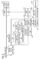
- FIG. 1 is a block diagram showing an example of a functional configuration of the liquid crystal display apparatus according to the present embodiment.
- a feature amount detecting unit 101 detects and outputs a brightness feature amount of inputted image data for each block.
- image data of an inputted frame includes a background image
- a background detecting unit 102 detects a block in which a background is displayed (background-displaying block). Specifically, for each block, the background detecting unit 102 determines whether or not the block is a background-displaying block and outputs a result of the determination.
- a dark region of an image is to be used as a background region (still image background region).
- an auxiliary object detecting unit detects a block in which the auxiliary object is displayed. Moreover, in the present embodiment, an image of an auxiliary object is assumed to be brighter than a background image. Specifically, for each block, the feature amount variation detecting unit 103 determines whether or not a brightness feature amount of the block has varied over time (from a frame immediately preceding the current frame (a preceding frame) to the current frame), and outputs a result of the determination. The variation area calculating unit 104 calculates a total area (number) of blocks which is determined that brightness feature amount has varied over time by the feature amount variation detecting unit 103.
- the variation area calculating unit 104 determines whether or not the variation of the brightness feature amount over time detected by the feature amount variation detecting unit 103 is attributable to displaying an auxiliary object. Specifically, when the total area of blocks which is determined that brightness feature amount has varied over time is smaller than a predetermined threshold, the variation area calculating unit 104 determines that the variation of the brightness feature amount over time is attributable to displaying an auxiliary object.
- the variation area calculating unit 104 determines that the variation of the brightness feature amount over time is attributable to displaying an auxiliary object, the variation area calculating unit 104 determines that a block which is determined that brightness feature amount has varied over time is a block in which the auxiliary object is displayed and outputs a result of the determination.
- a block which is determined that brightness feature amount has varied over time is a block in which the auxiliary object is displayed and outputs a result of the determination.
- an area of an auxiliary object such as a cursor is relatively small and that a threshold is set which corresponds to an area of the auxiliary object assumed in advance.
- a backlight brightness calculating unit 105 calculates an emission brightness (a backlight emission brightness) of a backlight 109 based on a brightness feature amount of image data of the current frame. Specifically, the backlight emission brightness is calculated for each block so that a block of a bright image has a higher backlight emission brightness than a block of a dark image.
- a backlight brightness variation control unit 106 determines whether or not the auxiliary object is displayed in a background-displaying block based on a detection result by the background detecting unit 102 and a detection result by the auxiliary object detecting unit (a determination of an object block that is a block in which the background and the auxiliary object are displayed). In addition, the backlight brightness variation control unit 106 controls the backlight emission brightness based on a result of the determination regarding whether or not the auxiliary object is displayed in a background-displaying block.
- the backlight brightness variation control unit 106 approximates the backlight emission brightness of a background-displaying block (object block) in which the auxiliary object is displayed to the backlight emission brightness of other background-displaying blocks.
- the backlight brightness variation control unit 106 adjusts the backlight emission brightness of all blocks so as to equal the backlight emission brightness of the blocks in a previous frame.
- the backlight brightness variation control unit 106 adjusts the backlight emission brightness of each of all blocks so as to equal the backlight emission brightness of the blocks in the preceding frame.
- the backlight brightness variation control unit 106 when it is determined that the auxiliary object is displayed in a background-displaying block, performs control so that emission brightness of the entire backlight does not vary over time. Accordingly, the backlight emission brightness of the background-displaying block in which the auxiliary object is displayed becomes equal to the backlight emission brightness of the same block when the auxiliary object is not displayed. As a result, the backlight emission brightness of the background-displaying block in which the auxiliary object is displayed can be approximated to the backlight emission brightness of other background-displaying blocks.
- a previous frame is not limited to a preceding frame (a frame immediately preceding the current frame).
- the previous frame may precede the current frame by any number of frames as long as the auxiliary object is not displayed in the frame.
- the backlight brightness variation control unit 106 performs the emission brightness control described above by controlling a backlight brightness storage unit 107 described below.
- the backlight brightness storage unit 107 stores the backlight emission brightness of each block calculated by the backlight brightness calculating unit 105. In addition, the backlight brightness storage unit 107 outputs a stored backlight emission brightness of each block.
- a backlight control value calculating unit 108 calculates and outputs a control value for each block so that a light source (a light source of the backlight 109) of the block emits light at the backlight emission brightness of the same block outputted from the backlight brightness storage unit 107. For example, when the backlight emission brightness of each block is controlled by pulse-width modulation, a pulse width value is outputted for each block as a control value.
- the backlight 109 (backlight module) has a light source (one or more light sources) for each block.
- the light sources of the respective blocks can be controlled independently.
- the backlight 109 causes the light source of each block to emit light based on the control value of the block as calculated by the backlight control value calculating unit 108. In other words, the backlight 109 causes the light source of each block to emit light at the backlight emission brightness of the same block outputted from the backlight brightness storage unit 107.
- a gain calculating unit 110 calculates, for each pixel, a brightness (display brightness; first display brightness) on a display screen (screen) of the liquid crystal display apparatus in a case where light is emitted by the backlight 109 based on the control value of each block as calculated by the backlight control value calculating unit 108.
- the gain calculating unit 110 calculates a multiplier value (gain) so that a maximum value of the first display brightness is consistent with a maximum value of a display brightness (second display brightness) in a case where the light is emitted by the backlight 109 at a predetermined emission brightness.
- the display brightness may be calculated on a per-block basis instead of on a per-pixel basis.
- a gain multiplying unit 111 multiplies image data of the current frame (respective pixel values of the current frame) by the gain calculated by the gain calculating unit 110, and outputs image data of the current frame that has been multiplied by the gain.
- a liquid crystal panel 112 (LCD module) has a plurality of liquid crystal elements. A transmittance of the plurality of liquid crystal elements is controlled based on image data (the image data multiplied by the gain) inputted to the liquid crystal panel 112. An image is displayed as light from the backlight 109 is transmitted through the liquid crystal panel 112 (the plurality of liquid crystal elements described above).
- FIG. 8 shows an example of a displayed image in a conventional liquid crystal display apparatus that controls a backlight emission brightness for each block based on a brightness feature amount of image data of an inputted frame.
- the displayed image is made up of a still image constituted by a main object region and a still image background region, a cursor, and a user operation menu.
- FIG. 8 shows a cursor being moved to a user operation button in a user operation menu (the cursor being moved from a position C1 to a position C2) in response to the use of a mouse by a user.
- a backlight emission brightness of a block to which a cursor belongs is determined based on a brightness feature amount that includes a brightness feature amount of the cursor. Therefore, due to the cursor being displayed, a display brightness around the cursor varies specifically. For example, when an image of the cursor is a bright image, the backlight emission brightness of a block to which the cursor belongs becomes higher compared to a case where the cursor does not belong to the block. Therefore, the display brightness around the cursor increases specifically, and image quality around the cursor deteriorates. Such a variation in display brightness creates a feeling of discomfort in a user. In other words, such a variation in display brightness creates a feeling of interference in terms of image quality.
- step S01 for each block, the feature amount detecting unit 101 detects a maximum brightness value (maximum pixel value) of image data of the block from image data of a current frame as a brightness feature amount of the block.
- step S02 the background detecting unit 102 detects a block in which the maximum brightness value of image data is equal to or smaller than a predetermined value in at least the current frame or a preceding frame as a block B (background-displaying block) belonging to a still image background region.
- a block in which the maximum brightness value of image data is equal to or smaller than a predetermined value in the current frame may be set as the block B belonging to a still image background region, or a block in which the maximum brightness value of image data is equal to or smaller than a predetermined value in the preceding frame may be set as the block B belonging to a still image background region.
- a block in which the maximum brightness value of image data is equal to or smaller than a predetermined value in both the current frame and the preceding frame may be set as the block B belonging to a still image background region.
- step S03 for each block, the feature amount variation detecting unit 103 calculates a difference value between the maximum brightness value of image data in the preceding frame and the maximum brightness value of image data in the current frame.
- the feature amount variation detecting unit 103 detects a block in which the difference value is equal to or larger than a predetermined value and, at the same time, the maximum brightness value of image data in the current frame is larger than the maximum brightness value of image data in the preceding frame as a block P in which a brightness feature amount has varied over time.
- the variation area calculating unit 104 calculates a total number Q of the blocks P.
- the backlight brightness calculating unit 105 calculates a backlight emission brightness R of each block from the maximum brightness values of the respective blocks detected in step S01. For example, the backlight brightness calculating unit 105 uses a lookup table (such as a function that determines a relationship between a maximum brightness value of image data and a backlight emission brightness) stored in advance to calculate the backlight emission brightness R of each block.
- a lookup table such as a function that determines a relationship between a maximum brightness value of image data and a backlight emission brightness
- step S05 the variation area calculating unit 104 determines whether or not the total number Q calculated in step S03 is smaller than a predetermined number.
- the variation area calculating unit 104 determines that the variation of the brightness feature amount over time detected in step S03 is attributable to displaying of an auxiliary object. This is because an area of an auxiliary object such as a cursor is assumed to be relatively small.
- the variation area calculating unit 104 determines that the block P (a block in which the brightness feature amount has varied over time) detected in step S03 is a block in which an auxiliary object is displayed.
- step S6 when the total number Q is equal to or larger than a predetermined number, the variation area calculating unit 104 determines that the variation of the brightness feature amount over time detected in step S03 is not attributable to displaying of an auxiliary object (for example, attributable to a change of a displayed image (still image)). The processing then proceeds to step S07.
- step S06 the backlight brightness variation control unit 106 determines whether a same block as the block B (background-displaying block) detected in step S02 is included in the blocks P (blocks in which the auxiliary object is displayed) detected in step S03.
- the backlight brightness variation control unit 106 determines that the auxiliary object is now displayed in the background-displaying block (which is a block in which the auxiliary object had not been displayed in a preceding frame).
- the processing then proceeds to step S08.
- the processing also proceeds to step S08 when no blocks P have been detected in step S03 (when the total number Q is 0).
- the backlight brightness variation control unit 106 determines that the image data of the current frame and the image data in the preceding frame are the same or that the block in which the auxiliary object is displayed is the same in the current frame and the preceding frame.
- the backlight brightness variation control unit 106 determines that the auxiliary object has been displayed in a block (a block in which the auxiliary object had not been displayed in the preceding frame) other than the background-displaying block. Even if the auxiliary object is displayed at such a position, the deterioration of image quality described earlier does not occur easily. In other words, even if the auxiliary object is displayed at such a position, the feeling of discomfort in a user (the feeling of interference in terms of image quality) described earlier is low. Therefore, in such a case, the processing proceeds to step S07.
- step S07 the backlight brightness variation control unit 106 replaces a backlight emission brightness O for each block stored in a memory M of the backlight brightness storage unit 107 with the backlight emission brightness R for each block calculated in step S04.
- the processing then proceeds to step S08.
- step S08 the backlight brightness variation control unit 106 outputs the backlight emission brightness O for each block stored in the memory M of the backlight brightness storage unit 107 to the backlight control value calculating unit 108 and the gain calculating unit 110. At this point, the backlight emission brightness O for each block stored in the memory M is not released and is retained.
- the backlight emission brightness O for each block stored in the memory M is retained without being updated.
- the backlight emission brightness O for each block stored in the memory M is also retained without being updated when no blocks P have been detected in step S03 (when the total number Q is 0).
- the backlight control value calculating unit 108 calculates a control value for each block from the backlight emission brightness O acquired for each block and outputs the control value.
- the light sources the light source of the backlight 109 of all blocks respectively emit light at a backlight emission brightness of the blocks in a preceding frame.
- the backlight 109 emits light by a method similar to that conventionally used.
- the light source of the backlight 109 emits light at a backlight emission brightness based on the brightness feature amount of the image data in the current frame.
- the gain calculating unit 110 calculates a gain using the backlight emission brightness O acquired for each block and outputs the gain to the gain multiplying unit 111.
- the gain multiplying unit 111 multiplies the image data of the current frame by the acquired gain and outputs the image data multiplied by the gain to the liquid crystal panel 112. Accordingly, a transmittance of each liquid crystal element of the liquid crystal panel 112 is controlled based on the image data multiplied by the gain.
- a backlight emission brightness of the background-displaying block in which the auxiliary object is displayed is set so as to equal the backlight emission brightness of the block in a previous frame.
- the backlight emission brightness of the background-displaying block in which the auxiliary object is displayed can be approximated to the backlight emission brightness of other background-displaying blocks.
- a specific variation (image quality deterioration) of the display brightness around the object can be suppressed. In other words, a deterioration of image quality around the predetermined object can be suppressed, and image quality of a displayed image can be improved.
- a brightness feature amount is a maximum brightness value (maximum pixel value)
- the brightness feature amount is not limited thereto.
- the brightness feature amount may be an average brightness value (average pixel value), a mode brightness value (mode pixel value), or a brightness histogram. Using such a brightness feature amount enables a variation of the brightness feature amount over time to be detected with higher accuracy than in a case where a maximum brightness value is used as the brightness feature amount.
- the present embodiment is configured such that a backlight emission brightness of a background-displaying block in which an auxiliary object is displayed is set equal to a backlight emission brightness of the same block in a previous frame
- the present invention is not limited to such a configuration.
- a configuration may be adopted in which a backlight emission brightness of a background-displaying block in which an auxiliary object is displayed is approximated to a backlight emission brightness of the same block in a previous frame. Even with such a configuration, an effect similar to that described above can be achieved.
- the present embodiment is configured such that a backlight emission brightness O for each block stored in a memory M is retained without being updated when it is determined that image data of a current frame and image data of a preceding frame are the same
- the present invention is not limited to such a configuration. For example, determinations can be made independently regarding whether or not image data of the current frame and image data of the preceding frame are the same and whether or not an auxiliary object is displayed in a background-displaying block.
- the backlight emission brightness O for each block stored in the memory M may be updated when it is determined that image data of the current frame and image data of the preceding frame are the same and, at the same time, an auxiliary object is not displayed in a background-displaying block.
- whether or not image data of the current frame and image data of the preceding frame are the same can be determined by comparing the image data of the current frame and the image data of the preceding frame with each other.
- the image data of the current frame and the image data of the preceding frame may be determined to be the same when the total number Q is zero, and the image data of the current frame and the image data of the preceding frame may be determined not to be the same when the total number Q is larger than zero.
- whether or not an auxiliary object is displayed in a background-displaying block may be determined separately from the determination regarding whether or not image data of the current frame and image data of the preceding frame are the same by using a method according to a third embodiment (to be described later).
- a block in which a maximum brightness value of image data in at least a current frame or a preceding frame is equal to or smaller than a predetermined value is considered to be a background-displaying block in the present embodiment
- a method of detecting a background-displaying block is not limited thereto.
- a block in which a maximum brightness value of image data in the current frame is equal to or smaller than a predetermined value may be assumed to be a background-displaying block.
- a condition applied when determining that a block of interest (a block that is a target of determination) is a background-displaying block
- a condition that a maximum brightness value of an image in a block adjacent to the block of interest is also equal to or smaller than a predetermined value or a condition that a brightness feature amount of the block of interest does not vary over time may be used.
- an average brightness value may be used in place of a maximum brightness value.
- a block in which an average brightness value of image data in at least a current frame or a preceding frame is equal to or smaller than a predetermined value may be assumed to be a background-displaying block.
- a condition applied when determining that a block of interest is a background-displaying block
- a condition that pixel values in the block of interest are approximately constant or flat pixel values of the block of interest are concentrated in a part of pixel values
- the background may be a black bar portion in side panel image data or letterbox image data.
- the masked region may be used as the background.
- the background-displaying block can be detected by referring to information acquired from the outside.
- information acquired from the outside include a genre of an image (whether or not an image is a cinematic video), positional information of a black bar portion, and positional information of a region masked by the user.
- the color of a background need not be limited to black. Any color may be used for the background.
- the background may be gray or blue.
- the present embodiment is configured such that when a same block as the block B is included in the blocks P, it is judged that an auxiliary object has been displayed in a background-displaying block (that is a block in which the auxiliary object had not been displayed in a preceding frame).
- a background-displaying block that is a block in which the auxiliary object had not been displayed in a preceding frame.
- the present invention is not limited to such a configuration. For example, when the number of background-displaying blocks among a plurality of blocks adjacent to a block in which the auxiliary object is displayed (a block whose brightness feature amount has varied over time) is equal to or larger than a predetermined number, it may be determined that an auxiliary object is displayed in a background-displaying block.
- a previous (for example, when the auxiliary object had not been displayed) result of detection of a background-displaying block may be stored in advance, and a determination regarding whether or not the auxiliary object is displayed in the background-displaying block may be made based on the detection result. Specifically, when a block in which the auxiliary object is displayed has been a background-displaying block in a previous frame, it may be determined that the auxiliary object is displayed in a background-displaying block. Moreover, a background-displaying block in which an auxiliary object is displayed may be identified. For example, when a same block as the block B is included in the blocks P, a same block P as the block B may be identified as a background-displaying block in which an auxiliary object is displayed.
- a block in which an auxiliary object is displayed when the number of background-displaying blocks among a plurality of blocks adjacent to a block in which the auxiliary object is displayed is equal to or larger than a predetermined number may be identified as a background-displaying block in which an auxiliary object is displayed.
- a block in which an auxiliary object is displayed may be identified as a background-displaying block in which an auxiliary object is displayed when the block in which the auxiliary object is displayed has been a background-displaying block in a previous frame.
- the gain calculating unit 110 stores, in advance, data representing a display brightness distribution when, for each block, light is emitted only from a light source (a light source of the backlight) of the block at a predetermined emission brightness to display a uniform image, and which is a display brightness distribution normalized by a display brightness at a position of the block.
- a position of each block is, for example, a center position of the block.
- the gain calculating unit 110 multiplies the aforementioned data (data representing a distribution of normalized display brightness) of the block by a backlight emission brightness (a backlight emission brightness outputted from the backlight brightness storage unit 107) of the block. Accordingly, a distribution of the backlight emission brightness when, for each block, light is emitted only from a light source (a light source of the backlight) of the block at the backlight emission brightness outputted from the backlight brightness storage unit 107 is obtained.
- the gain calculating unit 110 merges (adds up) the emission brightness distributions of the respective blocks.
- a distribution of the backlight emission brightness when light is emitted from the light sources of all blocks at the backlight emission brightness outputted from the backlight brightness storage unit 107 (a first emission brightness distribution) is obtained.
- the gain calculating unit 110 calculates a first display brightness distribution from the first emission brightness distribution and predetermined image data (a transmittance of each pixel in accordance with predetermined image data).
- the first display brightness distribution a distribution of display brightness when light is emitted from the light sources of all blocks at the backlight emission brightness outputted from the backlight brightness storage unit 107 to display an image in accordance with predetermined image data is calculated.
- the predetermined image data may or may not be a signal of the uniform image described above.
- the predetermined image data may be inputted image data of a current frame.
- the gain calculating unit 110 multiplies the data described above of the block by a predetermined emission brightness. Accordingly, a distribution of the backlight emission brightness when, for each block, light is emitted only from a light source (a light source of the backlight) of the block at a predetermined emission brightness is obtained.
- the gain calculating unit 110 merges (adds up) the emission brightness distributions of the respective blocks. Accordingly, a distribution of the backlight emission brightness when light is emitted from the light sources of all blocks at a predetermined emission brightness (a second emission brightness distribution) is obtained.
- the gain calculating unit 110 calculates a second display brightness distribution from the second emission brightness distribution and the predetermined image data described above. Specifically, as the second display brightness distribution, a distribution of display brightness when light is emitted from the light sources of all blocks at the predetermined emission brightness to display an image in accordance with predetermined image data is calculated. The gain calculating unit 110 then calculates a gain by dividing a maximum value of the second display brightness by a maximum value of the first display brightness.
- a backlight emission brightness of the background-displaying block in which the auxiliary object is displayed is adopted as a backlight emission brightness of a background-displaying block in which the auxiliary object is not displayed.
- the display brightness of the auxiliary object decreases and the visibility of the auxiliary object declines.
- the backlight emission brightness of the background-displaying block in which the auxiliary object is displayed is favorably set smaller than a backlight emission brightness determined based on an image of the block and, at the same time, higher than a backlight emission brightness determined based on an image of a background-displaying block in which the auxiliary object is not displayed. Accordingly, a decline in the visibility of the auxiliary object can be suppressed.
- an "image of a background-displaying block in which the auxiliary object is not displayed" is an image of a background-displaying block in which the auxiliary object is not displayed in the current frame or an image of a background-displaying block in which the auxiliary object is displayed in a previous frame.
- images of the auxiliary object and the background are not limited thereto.
- the background may be a bright image and the auxiliary object may be a dark image.
- a minimum brightness value of the image may be adopted as a brightness feature amount.
- a block in which a minimum brightness value of image data in at least a current frame or a preceding frame is equal to or larger than a predetermined value may be detected as a background-displaying block.
- blocks that satisfy the condition may be adopted as blocks in which the auxiliary object is displayed.
- FIG. 4 is a block diagram showing an example of a functional configuration of the liquid crystal display apparatus according to the present embodiment. Same functions as those of the first embodiment (FIG. 1) are denoted by same reference signs and descriptions thereof will be omitted.
- a feature amount detecting unit 201 detects, for each block, a maximum brightness value (maximum pixel value) and an average brightness value (average pixel value) of an image of the block from image data of an inputted frame (current frame) as a brightness feature amount of the block.
- a maximum pixel value variation detecting unit 203 detects blocks in which the maximum brightness value of image data has varied over time, and outputs a detection result. Specifically, the maximum pixel value variation detecting unit 203 detects blocks in which a maximum brightness value of image data in a current frame is larger than a maximum brightness value of image data in a preceding frame by a predetermined value or more, and outputs a detection result.
- An average pixel value variation detecting unit 204 detects blocks in which the average brightness value of image data has varied over time, and outputs a detection result. Specifically, the average pixel value variation detecting unit 204 detects blocks in which a difference between an average brightness value of image data in the current frame and an average brightness value of image data in the preceding frame is equal to or larger than a predetermined value, and outputs a detection result.
- a variation area calculating unit 213 calculates a total area (number) of blocks that have been detected by the maximum pixel value variation detecting unit 203 and, at the same time, have not been detected by the average pixel value variation detecting unit 204.
- a total area (number) of blocks is calculated in which the maximum brightness value of image data in the current frame is larger than the maximum brightness value of image data in the preceding frame by a predetermined value or more and, at the same time, a difference between the average brightness value of image data in the current frame and the average brightness value of image data in the preceding frame is smaller than a predetermined value.
- the variation area calculating unit 213 determines that the blocks satisfying the condition are blocks in which an auxiliary object is displayed and outputs a determination result.
- a size of an auxiliary object such as a cursor is often relatively small. Therefore, it is conceivable that an average brightness value of image data does not significantly vary even when an auxiliary object is displayed. In other words, when a maximum brightness value of image data varies significantly over time and an average brightness value of the image data also varies significantly over time, it is conceivable that the variation of the maximum brightness value over time is not caused by displaying an auxiliary object.
- the blocks satisfying the condition are assumed to be blocks in which an auxiliary object is displayed. Accordingly, blocks in which an auxiliary object is displayed can be detected with higher accuracy than in the first embodiment.
- FIG. 5 is a block diagram showing an example of a functional configuration of the liquid crystal display apparatus according to the present embodiment. Same functions as those of the first embodiment (FIG. 1) are denoted by same reference signs and descriptions thereof will be omitted.
- An external apparatus 313 is an external device that outputs positional information indicating an overlapping position of an auxiliary object in a displayed image.
- the external apparatus 313 is a PC.
- positional information of an auxiliary object is coordinate data which represents a displayed position of a mouse cursor and which is managed by an operating system running on the PC.
- An auxiliary object detecting unit 303 detects a block in which an auxiliary object is displayed based on positional information of the auxiliary object which is inputted from the external apparatus 313 that is separate from the liquid crystal display apparatus according to the present embodiment. Specifically, when the positional information of an auxiliary object is a coordinate of a display position of the auxiliary object, a block including the coordinate is assumed to be the block in which the auxiliary object is displayed.
- a backlight brightness variation control unit 306 adjusts a backlight emission brightness of the background-displaying block in which the auxiliary object is displayed so as to approximate (or become equal to) a backlight emission brightness in the same block in a previous frame.
- a block in which an auxiliary object is displayed is detected based on positional information of the auxiliary object that is inputted from an external device without using image data (brightness feature amount). Accordingly, blocks in which an auxiliary object is displayed can be detected with higher accuracy than in other embodiments.
- a total area of blocks whose brightness feature amount has varied over time need not be used to detect a block in which an auxiliary object is displayed as was the case in the first and second embodiments. Therefore, an auxiliary object that overlaps a moving image can also be detected.
- a backlight emission brightness of the background-displaying block in which the auxiliary object is displayed is set so as to equal the backlight emission brightness of the same block in a previous frame. Therefore, since a backlight emission brightness can be controlled based on image data of an inputted frame in blocks other than the background-displaying block in which the auxiliary object is displayed, contrast can be improved even when the auxiliary object is being displayed.
- FIG. 6 is a block diagram showing an example of a functional configuration of the liquid crystal display apparatus according to the present embodiment. Same functions as those of the first embodiment (FIG. 1) are denoted by same reference signs and descriptions thereof will be omitted.
- An isolated high-brightness block detecting unit 403 detects blocks in which a brightness value (a maximum brightness value, a minimum brightness value, a mode brightness value, an average brightness value, or the like) of image data is higher than a predetermined value and, at the same time, brightness values of images in all adjacent blocks are smaller than a predetermined value as an isolated high-brightness block.
- An isolated high-brightness block area calculating unit 404 calculates a total area (number) of isolated high-brightness blocks detected by the isolated high-brightness block detecting unit 403.
- the isolated high-brightness block area calculating unit 404 determines that the isolated high-brightness blocks are blocks in which an auxiliary object is displayed, and outputs a determination result.
- a backlight brightness variation control unit 406 determines a backlight emission brightness of the background-displaying block in which the auxiliary object is displayed based on a backlight emission brightness of an adjacent background-displaying block. For example, as the backlight emission brightness of the background-displaying block in which the auxiliary object is displayed, a backlight emission brightness of any one of adjacent background-displaying blocks may be adopted.
- a mode value or a mean value of the backlight emission brightness of the adjacent background-displaying blocks may be adopted.
- a configuration may be adopted in which the backlight emission brightness of the background-displaying block in which the auxiliary object is displayed is approximated to the backlight emission brightness of the adjacent background-displaying blocks, a mode value thereof, or a mean value thereof.
- a backlight emission brightness of the background-displaying block in which the auxiliary object is displayed is determined based on a backlight emission brightness of an adjacent background-displaying block. Accordingly, the backlight emission brightness of the background-displaying block in which the auxiliary object is displayed can be approximated to the backlight emission brightness of other background-displaying blocks.
- a specific variation (image quality deterioration) of the display brightness around the object can be suppressed. In other words, a deterioration of image quality around the predetermined object can be suppressed, and image quality of a displayed image can be improved.
- FIG. 7 is a block diagram showing an example of a functional configuration of the liquid crystal display apparatus according to the present embodiment. Same functions as those of the first embodiment (FIG. 1) are denoted by same reference signs and descriptions thereof will be omitted.
- An auxiliary object detecting unit 503 detects a block in which an auxiliary object is displayed using a same method as in the first, second, and fourth embodiments.
- a backlight brightness variation control unit 506 adjusts backlight emission brightness of all background-displaying block so as to be equal to each other.
- the backlight emission brightness of all background-displaying blocks is set to a predetermined value.
- the predetermined value is a backlight emission brightness that is determined based on an image of a background-displaying block in which the auxiliary object is not displayed.
- the predetermined value is not limited thereto.
- a value that is smaller than a backlight emission brightness that is determined based on an image of a background-displaying block in which the auxiliary object is displayed and, at the same time, higher than a backlight emission brightness that is determined based on an image of a background-displaying block in which the auxiliary object is not displayed may be adopted as the predetermined value.
- the predetermined value described above may be controlled by calculating an area of a background (or a total area (number) of blocks in which the background is displayed) and setting the predetermined value so that the larger the area, the larger the predetermined value.
- auxiliary object when it is determined that an auxiliary object is displayed in a background-displaying block, backlight emission brightness of all background-displaying blocks is adjusted so as to be equal to each other. Accordingly, when the auxiliary object is displayed in a background-displaying block, a specific variation (image quality deterioration) of the display brightness around the object can be suppressed.
- the respective functions of the first to fifth embodiments are interchangeable wherever possible.
- the auxiliary object detecting unit 303 according to the third embodiment may be used in place of the feature amount variation detecting unit 103 and the variation area calculating unit 104 according to the first embodiment.
- the backlight brightness variation control unit 306 according to the third embodiment may be used in place of the backlight brightness variation control unit 106 according to the first embodiment.
Landscapes
- Physics & Mathematics (AREA)
- Engineering & Computer Science (AREA)
- General Physics & Mathematics (AREA)
- Nonlinear Science (AREA)
- Theoretical Computer Science (AREA)
- Computer Hardware Design (AREA)
- Crystallography & Structural Chemistry (AREA)
- Optics & Photonics (AREA)
- Chemical & Material Sciences (AREA)
- Mathematical Physics (AREA)
- Liquid Crystal Display Device Control (AREA)
- Control Of Indicators Other Than Cathode Ray Tubes (AREA)
- Liquid Crystal (AREA)
Abstract
Description
Furthermore, a technique is proposed for maintaining an emission brightness of an entire backlight when displaying an OSD image to a brightness upon start of displaying of the OSD image (Patent Literature (PTL) 3). According to this technique, a display brightness of the OSD image can be stabilized.
an image display apparatus capable of controlling, for each block obtained by dividing a region of a screen, a backlight emission brightness based on image data of an inputted frame,
the image display apparatus comprising:
a detecting unit that detects a block in which a predetermined object is displayed;
a determining unit that determines an object block that is a block in which a background and the predetermined object are displayed based on a detection result by the detecting unit; and
a control unit that controls a backlight emission brightness for each block, wherein
the control unit approximates a backlight emission brightness of the object block to a backlight emission brightness of another block in which the background is displayed.
The present invention in its second aspect provides
an image display apparatus capable of controlling, for each block obtained by dividing a region of a screen, a backlight emission brightness based on image data of an inputted frame,
the image display apparatus comprising:
a detecting unit that detects a block in which a predetermined object is displayed;
a determining unit that determines an object block that is a block in which a background and the predetermined object are displayed based on a detection result by the detecting unit; and
a control unit that controls a backlight emission brightness for each block, wherein
the control unit controls a backlight emission brightness of the object block based on a backlight emission brightness of a block in which the background is displayed but the predetermined object is not displayed.
a control method of an image display apparatus capable of controlling, for each block obtained by dividing a region of a screen, a backlight emission brightness based on image data of an inputted frame,
the control method comprising:
a detecting step of detecting a block in which a predetermined object is displayed;
a determining step of determining an object block that is a block in which a background and the predetermined object are displayed based on a detection result in the detecting step; and
a control step of controlling a backlight emission brightness for each block, wherein
in the control step, a backlight emission brightness of the object block is approximated to a backlight emission brightness of another block in which the background is displayed.
The present invention in its fourth aspect provides
a control method of an image display apparatus capable of controlling, for each block obtained by dividing a region of a screen, a backlight emission brightness based on image data of an inputted frame,
the control method comprising:
a detecting step of detecting a block in which a predetermined object is displayed;
a determining step of determining an object block that is a block in which a background and the predetermined object are displayed based on a detection result in the detecting step; and
a control step of controlling a backlight emission brightness for each block, wherein
in the control step, a backlight emission brightness of the object block is controlled based on a backlight emission brightness of a block in which the background is displayed but the predetermined object is not displayed.
Further features of the present invention will become apparent from the following description of exemplary embodiments with reference to the attached drawings.
Hereinafter, a liquid crystal display apparatus (image display apparatus) and a control method thereof according to a first embodiment of the present invention will be described.
For example, as shown in FIG. 3, the liquid crystal display apparatus according to the present embodiment displays an image including a still image constituted by a main object region and a still image background region, a user operation menu, and a predetermined object. For example, the predetermined object is an auxiliary object that assists user operations. Examples of an auxiliary object include a cursor that moves in response to a mouse operation by a user.
In addition, the liquid crystal display apparatus according to the present embodiment has a configuration in which a backlight emission brightness can be controlled per block based on image data of an inputted frame so that the backlight emission brightness of a bright region in the image is higher than the backlight emission brightness of a dark region in the image. A backlight emission brightness is an emission brightness (an emission luminance) of a backlight. A block is a region obtained by dividing a region of a screen.
A feature
When image data of an inputted frame (current frame) includes a background image, a
Specifically, for each block, the feature amount
The variation
In the present embodiment, when it is determined that the auxiliary object is displayed in a background-displaying block (when the object block exists), the backlight brightness
Moreover, a previous frame is not limited to a preceding frame (a frame immediately preceding the current frame). For example, the previous frame may precede the current frame by any number of frames as long as the auxiliary object is not displayed in the frame.
Moreover, in the present embodiment, the backlight brightness
A backlight control
The backlight 109 (backlight module) has a light source (one or more light sources) for each block. The light sources of the respective blocks can be controlled independently. The
A
A liquid crystal panel 112 (LCD module) has a plurality of liquid crystal elements. A transmittance of the plurality of liquid crystal elements is controlled based on image data (the image data multiplied by the gain) inputted to the
First, in step S01, for each block, the feature
In step S02, the
When the total number Q is smaller than a predetermined number, the variation
When the total number Q is equal to or larger than a predetermined number, the variation
When a same block as the block B is included in the blocks P, the backlight brightness
When a same block as the block B is not included in the blocks P, the backlight brightness
In step S08, the backlight brightness
In addition, the
Moreover, while the present embodiment is configured such that a backlight emission brightness of a background-displaying block in which an auxiliary object is displayed is set equal to a backlight emission brightness of the same block in a previous frame, the present invention is not limited to such a configuration. Alternatively, a configuration may be adopted in which a backlight emission brightness of a background-displaying block in which an auxiliary object is displayed is approximated to a backlight emission brightness of the same block in a previous frame. Even with such a configuration, an effect similar to that described above can be achieved.
Furthermore, the background may be a black bar portion in side panel image data or letterbox image data. In addition, in a case where a user has masked a region that is not of interest in an image with a black image by using an image viewer function or the like in order to improve image visibility, the masked region may be used as the background. When detecting a block in such regions (a black bar portion or a region masked by the user) as a background-displaying block, the background-displaying block can be detected by referring to information acquired from the outside. Examples of information acquired from the outside include a genre of an image (whether or not an image is a cinematic video), positional information of a black bar portion, and positional information of a region masked by the user. Furthermore, the color of a background need not be limited to black. Any color may be used for the background. For example, the background may be gray or blue.
Moreover, a background-displaying block in which an auxiliary object is displayed may be identified. For example, when a same block as the block B is included in the blocks P, a same block P as the block B may be identified as a background-displaying block in which an auxiliary object is displayed. A block in which an auxiliary object is displayed when the number of background-displaying blocks among a plurality of blocks adjacent to a block in which the auxiliary object is displayed is equal to or larger than a predetermined number may be identified as a background-displaying block in which an auxiliary object is displayed. A block in which an auxiliary object is displayed may be identified as a background-displaying block in which an auxiliary object is displayed when the block in which the auxiliary object is displayed has been a background-displaying block in a previous frame.
An example will be described below.
The
For each block, the
In a similar manner, for each block, the
The
Hereinafter, a liquid crystal display apparatus and a control method thereof according to a second embodiment of the present invention will be described. For example, in a similar manner to the first embodiment, the liquid crystal display apparatus according to the present embodiment displays an image including a still image, a user operation menu, and an auxiliary object. Moreover, a case where an image of the auxiliary object is brighter than an image of a background will be described below.
FIG. 4 is a block diagram showing an example of a functional configuration of the liquid crystal display apparatus according to the present embodiment. Same functions as those of the first embodiment (FIG. 1) are denoted by same reference signs and descriptions thereof will be omitted.
A maximum pixel value
An average pixel value
A variation
Hereinafter, a liquid crystal display apparatus and a control method thereof according to a third embodiment of the present invention will be described. Unlike the first and second embodiments, the image display apparatus according to the present embodiment is also capable of displaying moving images. In other words, the image display apparatus according to the present embodiment displays an image including one of or both a moving image and a still image, and an auxiliary object.
FIG. 5 is a block diagram showing an example of a functional configuration of the liquid crystal display apparatus according to the present embodiment. Same functions as those of the first embodiment (FIG. 1) are denoted by same reference signs and descriptions thereof will be omitted.
An auxiliary
When it is determined that the auxiliary object is displayed in a background-displaying block, a backlight brightness
Furthermore, in the present embodiment, when it is determined that the auxiliary object is displayed in a background-displaying block, a backlight emission brightness of the background-displaying block in which the auxiliary object is displayed is set so as to equal the backlight emission brightness of the same block in a previous frame. Therefore, since a backlight emission brightness can be controlled based on image data of an inputted frame in blocks other than the background-displaying block in which the auxiliary object is displayed, contrast can be improved even when the auxiliary object is being displayed.
Hereinafter, a liquid crystal display apparatus and a control method thereof according to a fourth embodiment of the present invention will be described. For example, an image display apparatus according to the present embodiment displays an image including one of or both a moving image and a still image, and an auxiliary object in a similar manner to the third embodiment. Moreover, a case will be described below in which an image of an auxiliary object is brighter than a background image.
FIG. 6 is a block diagram showing an example of a functional configuration of the liquid crystal display apparatus according to the present embodiment. Same functions as those of the first embodiment (FIG. 1) are denoted by same reference signs and descriptions thereof will be omitted.
An isolated high-brightness block
When it is determined that the auxiliary object is displayed in a background-displaying block, a backlight brightness
Hereinafter, a liquid crystal display apparatus and a control method thereof according to a fifth embodiment of the present invention will be described. For example, an image display apparatus according to the present embodiment displays an image including one of or both a moving image and a still image, and an auxiliary object in a similar manner to the third and fourth embodiments.
FIG. 7 is a block diagram showing an example of a functional configuration of the liquid crystal display apparatus according to the present embodiment. Same functions as those of the first embodiment (FIG. 1) are denoted by same reference signs and descriptions thereof will be omitted.
When it is determined that the auxiliary object is displayed in a background-displaying block (when the object block exists), a backlight brightness
Alternatively, the predetermined value described above may be controlled by calculating an area of a background (or a total area (number) of blocks in which the background is displayed) and setting the predetermined value so that the larger the area, the larger the predetermined value.
103 feature amount variation detecting unit
104, 213 variation area calculating unit
106, 306, 406, 506 backlight brightness variation control unit
203 maximum pixel value variation detecting unit
204 average pixel value variation detecting unit
303, 503 auxiliary object detecting unit
403 isolated high-brightness block detecting unit
404 isolated high-brightness block area calculating unit
Claims (18)
- An image display apparatus capable of controlling, for each block obtained by dividing a region of a screen, a backlight emission brightness based on image data of an inputted frame,
the image display apparatus comprising:
a detecting unit that detects a block in which a predetermined object is displayed;
a determining unit that determines an object block that is a block in which a background and the predetermined object are displayed based on a detection result by the detecting unit; and
a control unit that controls a backlight emission brightness for each block, wherein
the control unit approximates a backlight emission brightness of the object block to a backlight emission brightness of another block in which the background is displayed.
- An image display apparatus capable of controlling, for each block obtained by dividing a region of a screen, a backlight emission brightness based on image data of an inputted frame,
the image display apparatus comprising:
a detecting unit that detects a block in which a predetermined object is displayed;
a determining unit that determines an object block that is a block in which a background and the predetermined object are displayed based on a detection result by the detecting unit; and
a control unit that controls a backlight emission brightness for each block, wherein
the control unit controls a backlight emission brightness of the object block based on a backlight emission brightness of a block in which the background is displayed but the predetermined object is not displayed.
- The image display apparatus according to claim 1 or 2, wherein
the control unit approximates a backlight emission brightness of the object block to a backlight emission brightness of the same block in a previous frame.
- The image display apparatus according to claim 1 or 2, wherein
when the object block exists, the control unit approximates backlight emission brightness of each of all blocks to backlight emission brightness of the same blocks in a previous frame.
- The image display apparatus according to claim 3 or 4, wherein
the previous frame is a frame immediately preceding the inputted frame.
- The image display apparatus according to any one of claims 3 to 5, wherein
a backlight emission brightness in the previous frame is a backlight emission brightness when the predetermined object is not displayed.
- The image display apparatus according to claim 1 or 2, wherein
the control unit determines a backlight emission brightness of the object block based on a backlight emission brightness of a block in which the background is displayed from among blocks adjacent to the object block.
- The image display apparatus according to claim 1 or 2, wherein
when the object block exists, the control unit adjusts backlight emission brightness of all blocks, in which the background is displayed, to be the same.
- The image display apparatus according to any one of claims 1 to 8, wherein
image data of the predetermined object is brighter than image data of the background, and
the control unit sets a backlight emission brightness of the object block so as to be smaller than a backlight emission brightness determined based on image data of the object block and, at the same time, higher than a backlight emission brightness determined based on image data of a block in which the background is displayed but the predetermined object is not displayed.
- The image display apparatus according to any one of claims 1 to 9, wherein
image data of the predetermined object is brighter than image data of the background,
the image display apparatus further has a feature amount detecting unit that detects, for each block, a maximum brightness value of image data of the block from image data of the inputted frame, and
when the number of blocks satisfying a condition that a maximum brightness value of the image data of the inputted frame is larger than a maximum brightness value of image data of a frame immediately preceding the inputted frame by a predetermined value or more is equal to or larger than one and smaller than a predetermined number, the detecting unit assumes that a block satisfying the condition is a block in which the predetermined object is displayed.
- The image display apparatus according to any one of claims 1 to 9, wherein
image data of the predetermined object is brighter than image data of the background,
the image display apparatus further has a feature amount detecting unit that detects, for each block, a maximum brightness value and an average brightness value of image data of the block from image data of the inputted frame, and
when the number of blocks satisfying a condition that a maximum brightness value of the image data of the inputted frame is larger than a maximum brightness value of image data of a frame immediately preceding the inputted frame by a predetermined value or more and, at the same time, a difference between an average brightness value of the image data of the inputted frame and an average brightness value of image data of a frame immediately preceding the inputted frame is smaller than a predetermined value is equal to or larger than one and smaller than a predetermined number, the detecting unit assumes that a block satisfying the condition is a block in which the predetermined object is displayed.
- The image display apparatus according to any one of claims 1 to 9, wherein
image data of the predetermined object is brighter than image data of the background, and
when the number of blocks satisfying a condition that a brightness value of image data is higher than a predetermined value and, at the same time, a brightness value of image data of all adjacent blocks is smaller than a predetermined value is equal to or larger than one and smaller than a predetermined number, the detecting unit assumes that a block satisfying the condition is a block in which the predetermined object is displayed.
- The image display apparatus according to any one of claims 1 to 9, wherein
the detecting unit detects a block in which the predetermined object is displayed based on positional information of the predetermined object inputted from an external device.
- The image display apparatus according to any one of claims 1 to 13, wherein
when the number of blocks in which the background is displayed from among a plurality of blocks adjacent to a block in which the predetermined object is displayed is equal to or larger than a predetermined number, the determining unit determines that the block in which the predetermined object is displayed is the object block.
- The image display apparatus according to any one of claims 1 to 13, wherein
when a block in which the predetermined object is displayed is a block in which the background is displayed in a previous frame, the determining unit determines that the block in which the predetermined object is displayed is the object block.
- The image display apparatus according to any one of claims 1 to 15, wherein
the predetermined object is an auxiliary object that assists user operation.
- A control method of an image display apparatus capable of controlling, for each block obtained by dividing a region of a screen, a backlight emission brightness based on image data of an inputted frame,
the control method comprising:
a detecting step of detecting a block in which a predetermined object is displayed;
a determining step of determining an object block that is a block in which a background and the predetermined object are displayed based on a detection result in the detecting step; and
a control step of controlling a backlight emission brightness for each block, wherein
in the control step, a backlight emission brightness of the object block is approximated to a backlight emission brightness of another block in which the background is displayed.
- A control method of an image display apparatus capable of controlling, for each block obtained by dividing a region of a screen, a backlight emission brightness based on image data of an inputted frame,
the control method comprising:
a detecting step of detecting a block in which a predetermined object is displayed;
a determining step of determining an object block that is a block in which a background and the predetermined object are displayed based on a detection result in the detecting step; and
a control step of controlling a backlight emission brightness for each block, wherein
in the control step, a backlight emission brightness of the object block is controlled based on a backlight emission brightness of a block in which the background is displayed but the predetermined object is not displayed.
Priority Applications (4)
| Application Number | Priority Date | Filing Date | Title |
|---|---|---|---|
| CN201280062997.2A CN103999147A (en) | 2011-12-19 | 2012-12-06 | Image display apparatus and control method thereof |
| KR1020147019588A KR101647970B1 (en) | 2011-12-19 | 2012-12-06 | Image display apparatus and control method thereof |
| US14/353,638 US9501979B2 (en) | 2011-12-19 | 2012-12-06 | Image display apparatus and control method thereof |
| EP12860344.6A EP2795606A4 (en) | 2011-12-19 | 2012-12-06 | Image display apparatus and control method thereof |
Applications Claiming Priority (4)
| Application Number | Priority Date | Filing Date | Title |
|---|---|---|---|
| JP2011-277625 | 2011-12-19 | ||
| JP2011277625 | 2011-12-19 | ||
| JP2012257472A JP6071469B2 (en) | 2011-12-19 | 2012-11-26 | Image display apparatus and control method thereof |
| JP2012-257472 | 2012-11-26 |
Publications (1)
| Publication Number | Publication Date |
|---|---|
| WO2013094140A1 true WO2013094140A1 (en) | 2013-06-27 |
Family
ID=48668059
Family Applications (1)
| Application Number | Title | Priority Date | Filing Date |
|---|---|---|---|
| PCT/JP2012/007813 Ceased WO2013094140A1 (en) | 2011-12-19 | 2012-12-06 | Image display apparatus and control method thereof |
Country Status (6)
| Country | Link |
|---|---|
| US (1) | US9501979B2 (en) |
| EP (1) | EP2795606A4 (en) |
| JP (1) | JP6071469B2 (en) |
| KR (1) | KR101647970B1 (en) |
| CN (1) | CN103999147A (en) |
| WO (1) | WO2013094140A1 (en) |
Families Citing this family (13)
| Publication number | Priority date | Publication date | Assignee | Title |
|---|---|---|---|---|
| US9299297B2 (en) * | 2011-09-05 | 2016-03-29 | Canon Kabushiki Kaisha | Image display apparatus and method for controlling the same |
| KR101992310B1 (en) * | 2013-03-25 | 2019-09-30 | 엘지디스플레이 주식회사 | Image processing method for display apparatus and image processing apparatus |
| JP2015018219A (en) * | 2013-06-14 | 2015-01-29 | キヤノン株式会社 | Image display apparatus and control method thereof |
| WO2015146471A1 (en) * | 2014-03-24 | 2015-10-01 | 富士フイルム株式会社 | Photo shooting apparatus |
| JP6493664B2 (en) * | 2015-03-04 | 2019-04-03 | パナソニックIpマネジメント株式会社 | Lighting control device, lighting system, and program |
| US20170061894A1 (en) * | 2015-08-26 | 2017-03-02 | Canon Kabushiki Kaisha | Image display apparatus |
| CN105513546B (en) | 2016-03-02 | 2018-09-11 | 京东方科技集团股份有限公司 | backlight adjusting method and device, display device |
| JP2018013696A (en) * | 2016-07-22 | 2018-01-25 | キヤノン株式会社 | Image processing apparatus and display apparatus |
| JP6896507B2 (en) * | 2017-05-25 | 2021-06-30 | キヤノン株式会社 | Display device and its control method |
| CN108470547B (en) * | 2018-05-17 | 2020-11-10 | 京东方科技集团股份有限公司 | Backlight control method of display panel, computer readable medium and display device |
| CN111258523A (en) * | 2020-01-16 | 2020-06-09 | 深圳市奥拓电子股份有限公司 | Huge image display system fused in venue and control method |
| JP7596115B2 (en) * | 2020-10-22 | 2024-12-09 | キヤノン株式会社 | Display device and control method thereof |
| JP7737322B2 (en) * | 2022-02-04 | 2025-09-10 | シャープ株式会社 | Display device and display device control method |
Citations (8)
| Publication number | Priority date | Publication date | Assignee | Title |
|---|---|---|---|---|
| JP2002099250A (en) | 2000-09-21 | 2002-04-05 | Toshiba Corp | Display device |
| JP2005321424A (en) | 2004-05-06 | 2005-11-17 | Sharp Corp | Image display device |
| JP2010250173A (en) * | 2009-04-17 | 2010-11-04 | Hitachi Displays Ltd | Display device |
| JP2010271393A (en) * | 2009-05-19 | 2010-12-02 | Hitachi Ltd | Image display device |
| JP2011013294A (en) | 2009-06-30 | 2011-01-20 | Toshiba Corp | Information processing apparatus and luminance control method |
| JP2011145405A (en) * | 2010-01-13 | 2011-07-28 | Toshiba Corp | Liquid crystal display device |
| EP2378511A1 (en) | 2009-01-20 | 2011-10-19 | Panasonic Corporation | Display apparatus and display control method |
| JP2011232483A (en) * | 2010-04-27 | 2011-11-17 | Fujitsu Ten Ltd | Display control unit, display system, and display control method |
Family Cites Families (3)
| Publication number | Priority date | Publication date | Assignee | Title |
|---|---|---|---|---|
| JP2009139930A (en) * | 2007-11-13 | 2009-06-25 | Mitsumi Electric Co Ltd | Backlight device and liquid crystal display device using the same |
| WO2010035473A1 (en) | 2008-09-29 | 2010-04-01 | パナソニック株式会社 | Backlight device and display device |
| US8334866B2 (en) | 2009-09-17 | 2012-12-18 | Intellectual Discovery Co., Ltd. | Methods, systems, devices and components for reducing power consumption in an LCD backlit by LEDs |
-
2012
- 2012-11-26 JP JP2012257472A patent/JP6071469B2/en not_active Expired - Fee Related
- 2012-12-06 KR KR1020147019588A patent/KR101647970B1/en not_active Expired - Fee Related
- 2012-12-06 CN CN201280062997.2A patent/CN103999147A/en active Pending
- 2012-12-06 EP EP12860344.6A patent/EP2795606A4/en not_active Withdrawn
- 2012-12-06 WO PCT/JP2012/007813 patent/WO2013094140A1/en not_active Ceased
- 2012-12-06 US US14/353,638 patent/US9501979B2/en not_active Expired - Fee Related
Patent Citations (8)
| Publication number | Priority date | Publication date | Assignee | Title |
|---|---|---|---|---|
| JP2002099250A (en) | 2000-09-21 | 2002-04-05 | Toshiba Corp | Display device |
| JP2005321424A (en) | 2004-05-06 | 2005-11-17 | Sharp Corp | Image display device |
| EP2378511A1 (en) | 2009-01-20 | 2011-10-19 | Panasonic Corporation | Display apparatus and display control method |
| JP2010250173A (en) * | 2009-04-17 | 2010-11-04 | Hitachi Displays Ltd | Display device |
| JP2010271393A (en) * | 2009-05-19 | 2010-12-02 | Hitachi Ltd | Image display device |
| JP2011013294A (en) | 2009-06-30 | 2011-01-20 | Toshiba Corp | Information processing apparatus and luminance control method |
| JP2011145405A (en) * | 2010-01-13 | 2011-07-28 | Toshiba Corp | Liquid crystal display device |
| JP2011232483A (en) * | 2010-04-27 | 2011-11-17 | Fujitsu Ten Ltd | Display control unit, display system, and display control method |
Non-Patent Citations (1)
| Title |
|---|
| See also references of EP2795606A4 |
Also Published As
| Publication number | Publication date |
|---|---|
| JP2013148869A (en) | 2013-08-01 |
| KR101647970B1 (en) | 2016-08-12 |
| US20140232764A1 (en) | 2014-08-21 |
| JP6071469B2 (en) | 2017-02-01 |
| EP2795606A4 (en) | 2015-08-12 |
| EP2795606A1 (en) | 2014-10-29 |
| CN103999147A (en) | 2014-08-20 |
| KR20140105010A (en) | 2014-08-29 |
| US9501979B2 (en) | 2016-11-22 |
Similar Documents
| Publication | Publication Date | Title |
|---|---|---|
| US9501979B2 (en) | Image display apparatus and control method thereof | |
| US9773459B2 (en) | Image display apparatus that has a light emitting unit and method of controlling same | |
| US8836734B2 (en) | Display burn-in prevention device and method with motion analysis | |
| JP6039307B2 (en) | Image display apparatus and control method thereof | |
| US9293115B2 (en) | Display apparatus and control method thereof | |
| US9165510B2 (en) | Temporal control of illumination scaling in a display device | |
| EP2357636B1 (en) | Display apparatus and control circuit of the same | |
| JP6242092B2 (en) | Display device, display device control method, and program | |
| TWI576817B (en) | Display with Automatic Image Optimizing function and Related Image Adjusting Method | |
| US9299297B2 (en) | Image display apparatus and method for controlling the same | |
| JP5773636B2 (en) | Display control apparatus and control method thereof | |
| US9786216B2 (en) | Display apparatus, light-emitting device, and control method of display apparatus | |
| US9396700B2 (en) | Display apparatus and control method thereof | |
| JP2015176137A (en) | Image display device, light emitting device, and control method thereof | |
| WO2014038572A1 (en) | Image display device, control method for image display device, control program for image display device and recording medium on which control program is recorded | |
| JP6818781B2 (en) | Display device and its control method | |
| JP6180135B2 (en) | Image display apparatus and control method thereof | |
| JP2015088998A (en) | Display device, method of controlling the same, and program | |
| JP2019168603A (en) | Display device and method for controlling the same | |
| JP5990740B2 (en) | Display device, video type determination device, display device driving method, and video type determination method | |
| JP2018031955A (en) | Display device | |
| JP2015212783A (en) | Image display device, method for controlling image display device, and program | |
| JP5331020B2 (en) | Display control apparatus, display system, and display control method | |
| JP2015022123A (en) | Display device, control method of display device, and program | |
| JP2015222297A (en) | Image display device and control method thereof |
Legal Events
| Date | Code | Title | Description |
|---|---|---|---|
| 121 | Ep: the epo has been informed by wipo that ep was designated in this application |
Ref document number: 12860344 Country of ref document: EP Kind code of ref document: A1 |
|
| WWE | Wipo information: entry into national phase |
Ref document number: 14353638 Country of ref document: US |
|
| NENP | Non-entry into the national phase |
Ref country code: DE |
|
| ENP | Entry into the national phase |
Ref document number: 20147019588 Country of ref document: KR Kind code of ref document: A |
|
| REEP | Request for entry into the european phase |
Ref document number: 2012860344 Country of ref document: EP |
|
| WWE | Wipo information: entry into national phase |
Ref document number: 2012860344 Country of ref document: EP |