WO2013094188A1 - 異常検出方法 - Google Patents
異常検出方法 Download PDFInfo
- Publication number
- WO2013094188A1 WO2013094188A1 PCT/JP2012/008095 JP2012008095W WO2013094188A1 WO 2013094188 A1 WO2013094188 A1 WO 2013094188A1 JP 2012008095 W JP2012008095 W JP 2012008095W WO 2013094188 A1 WO2013094188 A1 WO 2013094188A1
- Authority
- WO
- WIPO (PCT)
- Prior art keywords
- temperature sensor
- gas temperature
- egr
- value
- intake manifold
- Prior art date
- Legal status (The legal status is an assumption and is not a legal conclusion. Google has not performed a legal analysis and makes no representation as to the accuracy of the status listed.)
- Ceased
Links
Images

Classifications
-
- G—PHYSICS
- G01—MEASURING; TESTING
- G01K—MEASURING TEMPERATURE; MEASURING QUANTITY OF HEAT; THERMALLY-SENSITIVE ELEMENTS NOT OTHERWISE PROVIDED FOR
- G01K15/00—Testing or calibrating of thermometers
- G01K15/007—Testing
-
- F—MECHANICAL ENGINEERING; LIGHTING; HEATING; WEAPONS; BLASTING
- F02—COMBUSTION ENGINES; HOT-GAS OR COMBUSTION-PRODUCT ENGINE PLANTS
- F02D—CONTROLLING COMBUSTION ENGINES
- F02D41/00—Electrical control of supply of combustible mixture or its constituents
- F02D41/22—Safety or indicating devices for abnormal conditions
- F02D41/222—Safety or indicating devices for abnormal conditions relating to the failure of sensors or parameter detection devices
-
- F—MECHANICAL ENGINEERING; LIGHTING; HEATING; WEAPONS; BLASTING
- F02—COMBUSTION ENGINES; HOT-GAS OR COMBUSTION-PRODUCT ENGINE PLANTS
- F02M—SUPPLYING COMBUSTION ENGINES IN GENERAL WITH COMBUSTIBLE MIXTURES OR CONSTITUENTS THEREOF
- F02M26/00—Engine-pertinent apparatus for adding exhaust gases to combustion-air, main fuel or fuel-air mixture, e.g. by exhaust gas recirculation [EGR] systems
- F02M26/49—Detecting, diagnosing or indicating an abnormal function of the EGR system
-
- G—PHYSICS
- G01—MEASURING; TESTING
- G01M—TESTING STATIC OR DYNAMIC BALANCE OF MACHINES OR STRUCTURES; TESTING OF STRUCTURES OR APPARATUS, NOT OTHERWISE PROVIDED FOR
- G01M99/00—Subject matter not provided for in other groups of this subclass
- G01M99/002—Thermal testing
-
- F—MECHANICAL ENGINEERING; LIGHTING; HEATING; WEAPONS; BLASTING
- F02—COMBUSTION ENGINES; HOT-GAS OR COMBUSTION-PRODUCT ENGINE PLANTS
- F02D—CONTROLLING COMBUSTION ENGINES
- F02D2200/00—Input parameters for engine control
- F02D2200/02—Input parameters for engine control the parameters being related to the engine
- F02D2200/021—Engine temperature
-
- F—MECHANICAL ENGINEERING; LIGHTING; HEATING; WEAPONS; BLASTING
- F02—COMBUSTION ENGINES; HOT-GAS OR COMBUSTION-PRODUCT ENGINE PLANTS
- F02D—CONTROLLING COMBUSTION ENGINES
- F02D2200/00—Input parameters for engine control
- F02D2200/02—Input parameters for engine control the parameters being related to the engine
- F02D2200/04—Engine intake system parameters
- F02D2200/0414—Air temperature
-
- F—MECHANICAL ENGINEERING; LIGHTING; HEATING; WEAPONS; BLASTING
- F02—COMBUSTION ENGINES; HOT-GAS OR COMBUSTION-PRODUCT ENGINE PLANTS
- F02D—CONTROLLING COMBUSTION ENGINES
- F02D2400/00—Control systems adapted for specific engine types; Special features of engine control systems not otherwise provided for; Power supply, connectors or cabling for engine control systems
- F02D2400/08—Redundant elements, e.g. two sensors for measuring the same parameter
-
- F—MECHANICAL ENGINEERING; LIGHTING; HEATING; WEAPONS; BLASTING
- F02—COMBUSTION ENGINES; HOT-GAS OR COMBUSTION-PRODUCT ENGINE PLANTS
- F02M—SUPPLYING COMBUSTION ENGINES IN GENERAL WITH COMBUSTIBLE MIXTURES OR CONSTITUENTS THEREOF
- F02M26/00—Engine-pertinent apparatus for adding exhaust gases to combustion-air, main fuel or fuel-air mixture, e.g. by exhaust gas recirculation [EGR] systems
- F02M26/02—EGR systems specially adapted for supercharged engines
- F02M26/04—EGR systems specially adapted for supercharged engines with a single turbocharger
- F02M26/05—High pressure loops, i.e. wherein recirculated exhaust gas is taken out from the exhaust system upstream of the turbine and reintroduced into the intake system downstream of the compressor
-
- F—MECHANICAL ENGINEERING; LIGHTING; HEATING; WEAPONS; BLASTING
- F02—COMBUSTION ENGINES; HOT-GAS OR COMBUSTION-PRODUCT ENGINE PLANTS
- F02M—SUPPLYING COMBUSTION ENGINES IN GENERAL WITH COMBUSTIBLE MIXTURES OR CONSTITUENTS THEREOF
- F02M26/00—Engine-pertinent apparatus for adding exhaust gases to combustion-air, main fuel or fuel-air mixture, e.g. by exhaust gas recirculation [EGR] systems
- F02M26/13—Arrangement or layout of EGR passages, e.g. in relation to specific engine parts or for incorporation of accessories
- F02M26/22—Arrangement or layout of EGR passages, e.g. in relation to specific engine parts or for incorporation of accessories with coolers in the recirculation passage
- F02M26/23—Layout, e.g. schematics
- F02M26/28—Layout, e.g. schematics with liquid-cooled heat exchangers
-
- F—MECHANICAL ENGINEERING; LIGHTING; HEATING; WEAPONS; BLASTING
- F02—COMBUSTION ENGINES; HOT-GAS OR COMBUSTION-PRODUCT ENGINE PLANTS
- F02M—SUPPLYING COMBUSTION ENGINES IN GENERAL WITH COMBUSTIBLE MIXTURES OR CONSTITUENTS THEREOF
- F02M26/00—Engine-pertinent apparatus for adding exhaust gases to combustion-air, main fuel or fuel-air mixture, e.g. by exhaust gas recirculation [EGR] systems
- F02M26/45—Sensors specially adapted for EGR systems
- F02M26/46—Sensors specially adapted for EGR systems for determining the characteristics of gases, e.g. composition
- F02M26/47—Sensors specially adapted for EGR systems for determining the characteristics of gases, e.g. composition the characteristics being temperatures, pressures or flow rates
-
- Y—GENERAL TAGGING OF NEW TECHNOLOGICAL DEVELOPMENTS; GENERAL TAGGING OF CROSS-SECTIONAL TECHNOLOGIES SPANNING OVER SEVERAL SECTIONS OF THE IPC; TECHNICAL SUBJECTS COVERED BY FORMER USPC CROSS-REFERENCE ART COLLECTIONS [XRACs] AND DIGESTS
- Y02—TECHNOLOGIES OR APPLICATIONS FOR MITIGATION OR ADAPTATION AGAINST CLIMATE CHANGE
- Y02T—CLIMATE CHANGE MITIGATION TECHNOLOGIES RELATED TO TRANSPORTATION
- Y02T10/00—Road transport of goods or passengers
- Y02T10/10—Internal combustion engine [ICE] based vehicles
- Y02T10/40—Engine management systems
Definitions
- the present invention relates to an abnormality detection method used for an internal combustion engine.
- EGR exhaust gas recirculation
- an EGR pipe is used between an appropriate position of the exhaust passage extending from the exhaust manifold to the exhaust pipe and an appropriate position of the intake passage extending from the intake pipe to the intake manifold.
- the EGR gas is connected and recirculated through the EGR pipe.
- OBD systems On Board Diagnostic Systems
- Detection / monitoring is performed, an alarm is displayed when an abnormality occurs to notify the driver, and the details of the failure are stored and held.
- Patent Document 1 As prior art document information related to a technique for detecting characteristic abnormality of this type of sensor, for example, the following Patent Document 1 by the same applicant as the present invention has already been proposed.
- the deterioration of the EGR cooler over time described here is the inner peripheral surface of the heat transfer tube of the EGR cooler (generally, the EGR cooler takes the form of a shell-and-tube heat exchanger).
- the EGR cooler takes the form of a shell-and-tube heat exchanger.
- soot contained in the exhaust gas accumulates with time and heat exchange efficiency decreases.
- the present invention has been made in view of the above circumstances, and an object of the present invention is to provide an abnormality detection device that can accurately identify which of the EGR gas temperature sensor, intake manifold gas temperature sensor, and EGR cooler is abnormal. It is said.
- the present invention provides two cooling water temperature sensors for detecting the temperature of the cooling water entering the EGR cooler at the same position, and confirms that both are the same detection value, thereby determining the normality of the cooling water temperature sensor.
- the intake air temperature that will be measured by the intake manifold gas temperature sensor based on the measured value and the measured value of the intercooler outlet gas temperature sensor, and if there is a discrepancy between the calculated value and the measured value of the intake manifold gas temperature sensor, While the characteristic abnormality of the temperature sensor is determined, if there is no deviation, the normality of the EGR cooler, the EGR gas temperature sensor, and the intake manifold gas temperature sensor is determined, Further, when the calculated value of the EGR cooler efficiency is not within the normal range, it is determined whether or not the calculated value is excessively low, and when the calculated value is not excessively low, the characteristic abnormality of the EGR gas temperature sensor is determined, but is excessively low In some cases, the intake air temperature that will be measured by the intake manifold gas temperature sensor is calculated in the same manner as described above.
- the present invention relates to an abnormality detection method characterized by determining whether the EGR gas temperature sensor and the intake manifold gas temperature sensor are normal and determining an abnormality of the EGR cooler.
- the detected value of the intercooler outlet gas temperature sensor does not show an excessively high value during low load operation and does not show an excessively low value during high load operation, the detected value of the intercooler outlet gas temperature sensor is normal.
- the normality of the intercooler outlet gas temperature sensor is determined from being considered to be within the range.
- the detection value of the intercooler outlet gas temperature sensor does not indicate an excessively high value during low load operation and does not indicate an excessively low value during high load operation.
- the detection value does not exceed the threshold set at a temperature high enough to determine that the detection point should not be detected, and the detection value at the predetermined detection point in the high load operation region is This refers to a case where the temperature does not fall below the threshold set at a temperature that is low enough to determine that the detection point should not be detected.
- the intake air temperature that the intake manifold gas temperature sensor will measure is divided into cases based on the calculated value of the EGR cooler efficiency. It is possible to determine whether or not the EGR cooler, the EGR gas temperature sensor, and the intake manifold gas temperature sensor are normal by determining whether or not there is a difference between the calculated value and the actual measurement value of the intake manifold gas temperature sensor.
- the EGR cooler efficiency is calculated by calculating the exhaust temperature of the EGR cooler inlet calculated from the engine speed and load, the measured value by the EGR gas temperature sensor for detecting the exhaust temperature of the EGR cooler outlet, and the cooling water temperature sensor. Therefore, if the calculated value of the EGR cooler efficiency is within the normal range, the EGR cooler is not deteriorated so as to be abnormal, and the measured value of the EGR gas temperature sensor Can be regarded as having no abnormality.
- the measured value of the intake manifold gas temperature sensor that is not used for calculating the EGR cooler efficiency deviates from the calculated intake air temperature value that the intake manifold gas temperature sensor would measure, only the intake manifold gas temperature sensor is If the characteristic abnormality has occurred and no deviation has occurred, it is determined that all of the EGR cooler, the EGR gas temperature sensor, and the intake manifold gas temperature sensor are normal.
- the calculated value of the EGR cooler efficiency is not within the normal range, it is determined whether or not the calculated value is excessively low, and the EGR cooler is abnormally deteriorated (deterioration that leads to malfunction). If the EGR cooler efficiency is not excessively lowered as expected, it can be considered that there is an abnormality in the measured value of the EGR gas temperature sensor used for calculating the EGR cooler efficiency.
- the EGR cooler efficiency is so high that If the actual value of the intake manifold gas temperature sensor deviates from the calculated value when it has decreased excessively, the actual value of the EGR gas temperature sensor used to calculate the calculated value is considered to be abnormal. I can lose weight.
- the actual value of the intake manifold gas temperature sensor used to calculate the calculated value can be regarded as normal, so the calculated value of EGR cooler efficiency As a reason why the EGR cooler is not in the normal range, an abnormality due to the deterioration of the remaining EGR cooler is determined, and it is determined that the EGR gas temperature sensor and the intake manifold gas temperature sensor are normal.
- the detected values of the intercooler outlet gas temperature sensor, the intake manifold gas temperature sensor, and the EGR gas temperature sensor are the same when the engine is cold.
- the engine when the engine is cold, the engine is completely cooled and the warm-up priority control is performed with the EGR valve closed, so detection is performed by the intercooler outlet gas temperature sensor, intake manifold gas temperature sensor, and EGR gas temperature sensor.
- the temperature to be used should be the same value as the outside air temperature, and it is possible to confirm the accuracy of detection accuracy in the low temperature region in advance by confirming that each detected value is the same. It becomes.
- the intercooler outlet gas temperature sensor If the detection values of the intercooler outlet gas temperature sensor, the intake manifold gas temperature sensor, and the EGR gas temperature sensor are the same as the precondition when the engine is cold-started, the intercooler outlet gas temperature sensor The accuracy of the detection accuracy in the low temperature region of the intake manifold gas temperature sensor and the EGR gas temperature sensor can be confirmed in advance, thereby realizing more reliable detection of characteristic abnormality.
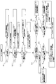
- FIG. 1 is an overall schematic diagram showing an embodiment of the present invention. It is a flowchart which shows the specific determination procedure performed with the control apparatus of FIG.
- FIG. 1 shows an embodiment of the present invention.
- reference numeral 1 denotes an engine on which a turbocharger 2 is mounted.
- the intake 4 guided from an air cleaner 3 is passed through an intake pipe 5 and the compressor of the turbocharger 2 is shown.
- the intake 4 pressurized by the compressor 2a is sent to the intercooler 6 to be cooled, and the intake 4 is further guided from the intercooler 6 to the intake manifold 7 to be distributed to each cylinder 8 of the engine 1. It is like that.
- the exhaust gas 9 discharged from each cylinder 8 of the engine 1 is sent to the turbine 2b of the turbocharger 2 through the exhaust manifold 10, and the exhaust gas 9 driving the turbine 2b is discharged out of the vehicle through the exhaust pipe 11. I have to do it.
- An end portion of the exhaust manifold 10 in the arrangement direction of the cylinders 8 and the intake pipe 5 downstream from the intercooler 6 are connected by an EGR pipe 12, and a part of the exhaust gas 9 is discharged from the exhaust manifold 10. It can be extracted and guided to the intake pipe 5 as EGR gas 9 '.
- the EGR pipe 12 is equipped with an EGR valve 13 for opening and closing the EGR pipe 12 as appropriate, and an EGR cooler 14 for cooling the EGR gas 9 ′ flowing through the EGR pipe 12.
- the temperature of the EGR gas 9 ' can be lowered by exchanging heat between the cooling water 15 guided from the engine 1 side and the EGR gas 9'.
- the temperature of the cooling water 15 entering the EGR cooler 14 is detected by two cooling water temperature sensors 16 provided at the same position in the front of the engine 1, and the exhaust temperature at the outlet of the EGR cooler 14 is detected by the EGR gas temperature sensor 17. Further, the temperature of the intake air 4 that has passed through the intercooler 6 is detected by the intercooler outlet gas temperature sensor 18, and the temperature of the intake air 4 that is mixed with the EGR gas 9 ′ and guided to the intake manifold 7. Is detected by the intake manifold gas temperature sensor 19, and the temperature of the intake air 4 (fresh air) guided from the air cleaner 3 is detected by the intake air temperature sensor 20.
- the detection signals 16a, 17a, 18a, 19a, and 20a from the cooling water temperature sensor 16, the EGR gas temperature sensor 17, the intercooler outlet gas temperature sensor 18, the intake manifold gas temperature sensor 19, and the intake air temperature sensor 20 are supplied to the engine. It is input to a control device 21 constituting a control computer (ECU: Electronic Control Unit).
- ECU Electronic Control Unit
- the control device 21 also receives a detection signal 22 a from an accelerator sensor 22 that detects the accelerator opening as a load of the engine 1 and a detection signal 23 a from a rotation sensor 23 that detects the rotation speed of the engine 1. It is like that.
- control device 21 determines whether or not the EGR cooler 14, the EGR gas temperature sensor 17 and the intake manifold gas temperature sensor 19 are normal by following the determination procedure as shown in the flowchart of FIG. ing.
- step S1 when the engine 1 is started in a cold state, in step S1, it is confirmed as a precondition that the detected values of the intercooler outlet gas temperature sensor 18, the intake manifold gas temperature sensor 19, and the EGR gas temperature sensor 17 are the same. It is like that.
- the intake temperature sensor 20 upstream of the intake pipe 5 should also show the same detection value, it is preferable to check the detection value of the intake temperature sensor 20 together, and many of the same detection values are regarded as normal. It is possible to consider that a small number showing different detection values is a characteristic abnormality.
- the next step S2 It is determined whether or not the two cooling water temperature sensors 16 have the same detection value. If the two detection values are different, the characteristic abnormality of the cooling water temperature sensor 16 is determined, and both detection values are the same. If so, the normality of the coolant temperature sensor 16 is determined.
- step S2 When the normality of the coolant temperature sensor 16 is determined in step S2, the process proceeds to the next step S3, and the detected value of the intercooler outlet gas temperature sensor 18 that detects the temperature of the intake air 4 that has passed through the intercooler 6 is excessive during low load operation.
- the intercooler outlet gas temperature sensor 18 is determined to be normal when it does not show a high value and does not show an excessively low value during high load operation.
- the detected value of the intercooler outlet gas temperature sensor 18 does not indicate an excessively high value during low load operation and does not indicate an excessively low value during high load operation, the detected value of the intercooler outlet gas temperature sensor 18 Since it is considered to be within the normal range, the normality of the intercooler outlet gas temperature sensor 18 is determined.
- the detection value of the intercooler outlet gas temperature sensor 18 does not indicate an excessively high value during low load operation and does not indicate an excessively low value during high load operation when it is a predetermined detection point in the low load operation region.
- the detected value at the predetermined detection point in the high load operation region does not exceed the threshold set at a high temperature that can be determined that the detected value should not be detected at the detection point. This refers to a case where the temperature does not fall below the threshold set at a temperature that is low enough to determine that the detection point should not be detected.
- step S4 the EGR cooler 14 inlet calculated from the rotational speed and load of the engine 1 is entered.
- the EGR cooler efficiency is calculated based on the calculated value of the exhaust gas temperature, the actually measured value by the EGR gas temperature sensor 17 for detecting the exhaust gas temperature at the outlet of the EGR cooler 14, and the actually measured value of the cooling water temperature sensor 16. It is determined whether or not the calculated efficiency value is within a normal range.
- EGR cooler efficiency (T GEGRIN -T GEGROUT ) / (T GEGRIN -T WEGRCIN ) ⁇ 100 (1)
- T GEGRIN EGR cooler inlet exhaust temperature
- T GEGROUT EGR cooler outlet exhaust temperature
- T WEGRCIN Cooling water temperature entering the EGR cooler
- the EGR cooler 14 is not deteriorated so as to be abnormal, and the measured value of the EGR gas temperature sensor 17 is also It can be considered that there is no abnormality.
- step S5 the process proceeds to step S5, and the temperature of the intake air 4 mixed with the EGR gas 9 'and guided to the intake manifold 7 is measured by the intake manifold gas temperature sensor 19, and Based on the current EGR rate, the actual measured value of the EGR gas temperature sensor 17, and the actual measured value of the intercooler outlet gas temperature sensor 18, the intake air temperature that the intake manifold gas temperature sensor 19 will measure is calculated, and the EGR cooler efficiency is calculated. It is determined whether the measured value of the intake manifold gas temperature sensor 19 that is not used for the intake gas is different from the calculated value of the intake air temperature that the intake manifold gas temperature sensor 19 will measure. If there is a difference, the intake manifold gas temperature sensor 19 If the characteristic abnormality of only 19 is confirmed and there is no deviation, the EGR cooler 14, the EGR gas temperature sensor 17, and the intake manifold gas temperature All normalities of the sensor 19 are determined.
- the intake air temperature that the intake manifold gas temperature sensor 19 will measure is calculated by the following equation (2).
- T GEGROUT EGR cooler outlet exhaust temperature
- T GICOUT Intercooler outlet intake temperature
- the intake flow rate of the engine 1 is obtained by multiplying the volume of each cylinder 8, the rotational speed of the engine 1 and the pump efficiency, and the intake air temperature sensor 20 is obtained from this intake flow rate.
- the difference obtained by subtracting the actual measurement value (fresh air amount) of EGR is obtained as the recirculation amount of the EGR gas 9 ', and the recirculation amount placed in the numerator and the swallowing flow rate placed in the denominator may be used as the EGR rate.
- step S4 determines whether the calculated value of the EGR cooler efficiency is excessively low.
- the threshold value may be determined using a threshold value. For this threshold value, an appropriate threshold value may be selected according to the flow rate of the EGR gas 9 'flowing through the EGR cooler 14.
- the EGR cooler efficiency does not decrease so much that it is assumed that the EGR cooler 14 is abnormally deteriorated, the measured value of the EGR gas temperature sensor 17 used for calculating the EGR cooler efficiency is abnormal. Therefore, the characteristic abnormality of the EGR gas temperature sensor 17 is determined.
- the calculated value of the EGR cooler efficiency is not within the normal range, it is not considered that only the measured value of the intake manifold gas temperature sensor 19 that is not used for calculating the EGR cooler efficiency is abnormal, and the intake manifold gas temperature Since it is difficult to consider that the sensor 19 and the EGR gas temperature sensor 17 cause the characteristic abnormality at the same time, the calculated value of the EGR cooler efficiency is not within the normal range, and it is assumed that the EGR cooler 14 is abnormally deteriorated.
- the EGR cooler efficiency is excessively decreased, it is determined in the next step S7 whether or not the actual measurement value of the intake manifold gas temperature sensor 19 is deviated from the calculated value. It can be considered that there is an abnormality in the actual measurement value of the EGR gas temperature sensor 17 used to calculate the EGR gas temperature sensor 17, so that the characteristic abnormality of the EGR gas temperature sensor 17 can be determined. To become.
- the measured value of the intake manifold gas temperature sensor 19 does not deviate from the calculated value unless the measured value of the EGR gas temperature sensor 17 is abnormal. Because.
- the measured value of the EGR gas temperature sensor 17 used for calculating the calculated value is normal. Abnormalities due to deterioration of the remaining EGR cooler 14 are determined as the reason why the calculated value is not in the normal range, and it is determined that the EGR gas temperature sensor 17 and the intake manifold gas temperature sensor 19 are normal.
- the EGR gas temperature sensor 17 and the intake manifold gas temperature sensor are considered while considering the possibility that the detected value is affected by the deterioration of the EGR cooler 14 with time and an abnormal value is output. 19.
- Exhaust gas purification technology that can accurately identify which of the EGR cooler 14 is abnormal, and is expected to be further refined in the future by establishing such an abnormality detection method. It is possible to contribute to the construction of an OBD system (On Board Diagnostic ⁇ ⁇ Systems) corresponding to the.
- the detection values of the intercooler outlet gas temperature sensor 18, the intake manifold gas temperature sensor 19, and the EGR gas temperature sensor 17 are confirmed as a precondition. Therefore, the accuracy of detection accuracy in the low temperature region of the intercooler outlet gas temperature sensor 18, the intake manifold gas temperature sensor 19, and the EGR gas temperature sensor 17 can be confirmed in advance. Abnormality detection can be realized.
- abnormality detection method of the present invention is not limited to the above-described embodiment, and it is needless to say that various changes can be made without departing from the gist of the present invention.
Landscapes
- Engineering & Computer Science (AREA)
- Chemical & Material Sciences (AREA)
- Combustion & Propulsion (AREA)
- Mechanical Engineering (AREA)
- General Engineering & Computer Science (AREA)
- Physics & Mathematics (AREA)
- General Physics & Mathematics (AREA)
- Exhaust-Gas Circulating Devices (AREA)
Abstract
冷却水温度センサ16とインタークーラ出口ガス温度センサ18の正常が確定されていることを前提条件として、EGRクーラ効率の計算値が正常範囲内にあるか否かを判定し、正常範囲内にある時にインマニガス温度センサ19が計測するであろう吸気温度の計算値とインマニガス温度センサ19の実測値との乖離の有無を判定する一方、正常範囲内にない時には計算値が過剰に低いかどうかを判定し、しかも、前記と同様にインマニガス温度センサ19の計算値と実測値との乖離の有無を判定し、これらの場合分けされた各判定に基づきEGRクーラ14とEGRガス温度センサ17とインマニガス温度センサ19が正常であるか否かを確定する。
Description
本発明は内燃機関に用いる異常検出方法に関する。
従来より、自動車のエンジン等では、排気側から排気ガスの一部を抜き出してEGRガスとして吸気側へと戻し、そのEGRガスでエンジン内での燃料の燃焼を抑制させて燃焼温度を下げることによりNOxの発生を低減するようにした、いわゆる排気ガス再循環(EGR:Exhaust Gas Recirculation)が行われている。
一般的に、この種の排気ガス再循環を行う場合には、排気マニホールドから排気管に亘る排気通路の適宜位置と、吸気管から吸気マニホールドに亘る吸気通路の適宜位置との間をEGRパイプにより接続し、該EGRパイプを通してEGRガスを再循環するようにしている。
尚、エンジンに再循環するEGRガスをEGRパイプの途中で冷却すると、EGRガスの温度が下がり且つその容積が小さくなることにより、エンジンの出力を余り低下させずに燃焼温度を低下して効果的にNOx(窒素酸化物)の発生を低減させることができるため、エンジンにEGRガスを再循環するEGRパイプの途中には水冷式のEGRクーラが装備されている。
一方、近年においては、OBDシステム(On Board Diagnostic Systems)と呼称される車載式故障診断装置が車両に搭載されるようになってきており、車両自身が排気浄化設備の異常(突発的故障)を検知・監視し、異常発生時に警報表示して運転者に知らせ且つその故障内容を記憶保持することが行われている。
尚、この種のセンサの特性異常を検出する技術に関連する先行技術文献情報としては、例えば、本発明と同じ出願人による下記の特許文献1等が既に提案されている。
しかしながら、排気浄化技術は今後更に高度精密化していくことになるため、EGRクーラの出口ガス温度を検出するEGRガス温度センサや、吸気マニホールド入口でインマニガス温度を検出するインマニガス温度センサに特性異常が発生しているか否かを判定することまで求められるようになってきているが、これらEGRガス温度センサ及びインマニガス温度センサに特性異常が発生しているか否かの判定を正確に行うことが難しいという問題があった。
即ち、これまでのセンサ類に関する特性異常の判定には、ある特定の運転条件下で通常有り得ない値を示した時に特性異常が発生していると判定する手法が採られてきたが、前述の如きEGRガス温度センサやインマニガス温度センサの場合には、上流側のEGRクーラの経時的な劣化により検出値が影響を受けて異常な値を出力している可能性が否定できず、EGRガス温度センサ、インマニガス温度センサ、EGRクーラの何れに異常が生じているのかを正確に特定することが難しかった。
尚、ここで述べているところのEGRクーラの経時的な劣化とは、該EGRクーラの伝熱チューブ(一般的にEGRクーラはシェルアンドチューブ型の熱交換器の形態を採る)の内周面に、排気ガス中に含まれる煤が経時的に堆積して熱交換効率が低下することを指している。
本発明は上述の実情に鑑みてなしたもので、EGRガス温度センサ、インマニガス温度センサ、EGRクーラの何れに異常が生じているのかを正確に特定し得る異常検出装置を提供することを目的としている。
本発明は、EGRクーラに入る冷却水の温度を検出する冷却水温度センサを同じ位置に二つ備えて両方が同じ検出値であることを確認することで前記冷却水温度センサの正常を確定すると共に、
インタークーラを経た吸気の温度を検出するインタークーラ出口ガス温度センサの検出値が低負荷運転時に過剰に高い値を示さず且つ高負荷運転時に過剰に低い値を示さない時に前記インタークーラ出口ガス温度センサの正常を確定し、
これら冷却水温度センサとインタークーラ出口ガス温度センサの正常が確定されていることを前提条件として、
エンジンの回転数と負荷から算出されるEGRクーラ入口の排気温度の計算値と、EGRクーラ出口の排気温度を検出するEGRガス温度センサによる実測値と、前記冷却水温度センサの実測値とに基づきEGRクーラ効率を算出し、
そのEGRクーラ効率の計算値が正常範囲内にある時に、EGRガスを混合されて吸気マニホールドに導かれる吸気の温度をインマニガス温度センサにより実測すると共に、現在のEGR率とEGRガス温度センサの実測値とインタークーラ出口ガス温度センサの実測値とに基づき前記インマニガス温度センサが計測するであろう吸気温度を算出し、その計算値とインマニガス温度センサの実測値とに乖離があればインマニガス温度センサの特性異常を確定する一方、乖離がなければEGRクーラとEGRガス温度センサとインマニガス温度センサの正常を確定し、
また、前記EGRクーラ効率の計算値が正常範囲内にない時に、該計算値が過剰に低いかどうかを判定し、過剰に低くない時にEGRガス温度センサの特性異常を確定する一方、過剰に低い時には前記と同様にしてインマニガス温度センサが計測するであろう吸気温度を算出し、その計算値が前記インマニガス温度センサの実測値とに乖離があればEGRガス温度センサの特性異常を確定し、乖離がなければEGRガス温度センサとインマニガス温度センサの正常を確定すると共に、EGRクーラの異常を確定することを特徴とする異常検出方法、に係るものである。
インタークーラを経た吸気の温度を検出するインタークーラ出口ガス温度センサの検出値が低負荷運転時に過剰に高い値を示さず且つ高負荷運転時に過剰に低い値を示さない時に前記インタークーラ出口ガス温度センサの正常を確定し、
これら冷却水温度センサとインタークーラ出口ガス温度センサの正常が確定されていることを前提条件として、
エンジンの回転数と負荷から算出されるEGRクーラ入口の排気温度の計算値と、EGRクーラ出口の排気温度を検出するEGRガス温度センサによる実測値と、前記冷却水温度センサの実測値とに基づきEGRクーラ効率を算出し、
そのEGRクーラ効率の計算値が正常範囲内にある時に、EGRガスを混合されて吸気マニホールドに導かれる吸気の温度をインマニガス温度センサにより実測すると共に、現在のEGR率とEGRガス温度センサの実測値とインタークーラ出口ガス温度センサの実測値とに基づき前記インマニガス温度センサが計測するであろう吸気温度を算出し、その計算値とインマニガス温度センサの実測値とに乖離があればインマニガス温度センサの特性異常を確定する一方、乖離がなければEGRクーラとEGRガス温度センサとインマニガス温度センサの正常を確定し、
また、前記EGRクーラ効率の計算値が正常範囲内にない時に、該計算値が過剰に低いかどうかを判定し、過剰に低くない時にEGRガス温度センサの特性異常を確定する一方、過剰に低い時には前記と同様にしてインマニガス温度センサが計測するであろう吸気温度を算出し、その計算値が前記インマニガス温度センサの実測値とに乖離があればEGRガス温度センサの特性異常を確定し、乖離がなければEGRガス温度センサとインマニガス温度センサの正常を確定すると共に、EGRクーラの異常を確定することを特徴とする異常検出方法、に係るものである。
而して、このようにした場合に、同じ位置に備えた二つの冷却水温度センサが同じ検出値を示したならば、二つの冷却水温度センサが同時に特性異常を起こすことは考え難いことから冷却水温度センサの正常が確定される。
また、インタークーラ出口ガス温度センサの検出値が低負荷運転時に過剰に高い値を示さず且つ高負荷運転時に過剰に低い値を示さないならば、インタークーラ出口ガス温度センサの検出値が正常な範囲内にあると考えられることからインタークーラ出口ガス温度センサの正常が確定される。
尚、インタークーラ出口ガス温度センサの検出値が低負荷運転時に過剰に高い値を示さず且つ高負荷運転時に過剰に低い値を示さない時とは、低負荷運転領域における所定の検出点での検出値が、当該検出点で検出されるはずがないと断定できるほどの高い温度に設定された閾値を超えておらず、しかも、高負荷運転領域における所定の検出点での検出値が、当該検出点で検出されるはずがないと断定できるほどの低い温度に設定された閾値を下まわっていない場合を指す。
そして、これら冷却水温度センサとインタークーラ出口ガス温度センサの正常が確定されたならば、EGRクーラ効率の計算値に基づいて場合分けした上で、インマニガス温度センサが計測するであろう吸気温度の計算値とインマニガス温度センサの実測値との乖離の有無を判定することにより、EGRクーラとEGRガス温度センサとインマニガス温度センサが正常であるか否かを判定することが可能となる。
即ち、EGRクーラ効率は、エンジンの回転数と負荷から算出されるEGRクーラ入口の排気温度の計算値と、EGRクーラ出口の排気温度を検出するEGRガス温度センサによる実測値と、冷却水温度センサの実測値とに基づいて算出されるため、EGRクーラ効率の計算値が正常範囲内にあるならば、EGRクーラに異常と言えるほどの劣化は生じておらず、EGRガス温度センサの実測値にも異常がないものと看做せる。
なぜなら、冷却水温度センサが正常であることは既に確定されているので、EGRクーラやEGRガス温度センサが正常でなければ、EGRクーラ効率の計算値が正常範囲内に収まらないからである。
依って、EGRクーラ効率の算出に用いられていないインマニガス温度センサの実測値が、インマニガス温度センサが計測するであろう吸気温度の計算値と乖離していれば、インマニガス温度センサのみが特性異常を生じており、乖離していなかったならば、EGRクーラとEGRガス温度センサとインマニガス温度センサの全てが正常であると確定される。
また、EGRクーラ効率の計算値が正常範囲内にないならば、該計算値が過剰に低いかどうかを判定し、EGRクーラに異常な劣化(機能不全に到るほどの劣化)が生じていると想定されるほどEGRクーラ効率が過剰に下がっていなければ、EGRクーラ効率の算出に用いたEGRガス温度センサの実測値に異常があるものと看做せる。
ここで、EGRクーラに異常な劣化が生じていると想定されるほどEGRクーラ効率が過剰に下がっていたとしても、EGRガス温度センサに特性異常が生じている可能性も残っているため、前記と同様にしてインマニガス温度センサの実測値が計算値と乖離しているかどうかを判定することにより、インマニガス温度センサに特性異常が生じているのか、EGRクーラに異常な劣化が生じているのかを判定することが可能となる。
即ち、EGRクーラ効率の計算値が正常範囲内にない以上、EGRクーラ効率の算出に用いられていないインマニガス温度センサの実測値だけが異常であるとは考えられず、また、インマニガス温度センサとEGRガス温度センサとが同時に特性異常を起こすことも考え難いので、EGRクーラ効率の計算値が正常範囲内になく、EGRクーラに異常な劣化が生じていると想定されるほどEGRクーラ効率が過剰に下がっていた場合に、インマニガス温度センサの実測値が計算値と乖離していたならば、該計算値を算出するのに用いたEGRガス温度センサの実測値に異常があるものと看做せる。
なぜなら、インタークーラ出口ガス温度センサが正常であることは既に確定されているので、EGRガス温度センサの実測値に異常がなければ、インマニガス温度センサの実測値が計算値と乖離しないからである。
そして、インマニガス温度センサの実測値と計算値とに乖離がなければ、該計算値の算出に用いたEGRガス温度センサの実測値が正常であると看做せるので、EGRクーラ効率の計算値が正常範囲にない理由として残ったEGRクーラの劣化による異常が確定されると共に、EGRガス温度センサとインマニガス温度センサが正常であると確定される。
更に、本発明においては、エンジンの冷機始動時にインタークーラ出口ガス温度センサとインマニガス温度センサとEGRガス温度センサの検出値が同じであることを前提条件として確認しておくことが好ましい。
即ち、エンジンの冷機始動時には、エンジンがすっかり冷えきっていて、EGRバルブを閉じた暖機優先の制御が行われるので、インタークーラ出口ガス温度センサとインマニガス温度センサとEGRガス温度センサとで検出される温度は全て外気温と変わらない値となるはずであり、夫々の検出値が同じであることを確認することで低温領域における検出精度の正確さを先行して確認しておくことが可能となる。
本発明の異常検出方法によれば、下記のような優れた効果を奏し得る。
(I)EGRクーラの経時的な劣化により検出値が影響を受けて異常な値を出力している可能性を考慮しながら、EGRガス温度センサ、インマニガス温度センサ、EGRクーラの何れに異常が生じているのかを正確に特定することができ、このような異常検出方法を確立することによって、今後更に高度精密化していくことが予想される排気浄化技術に対応したOBDシステム(On Board Diagnostic Systems)の構築に寄与することができる。
(II)エンジンの冷機始動時にインタークーラ出口ガス温度センサとインマニガス温度センサとEGRガス温度センサの検出値が同じであることを前提条件として確認するようにすれば、インタークーラ出口ガス温度センサとインマニガス温度センサとEGRガス温度センサの低温領域における検出精度の正確さを先行して確認しておくことができ、これにより一層確実な特性異常の検出を実現することができる。
以下、本発明の実施の形態を図面を参照しつつ説明する。
図1は本発明の一実施例を示すものであり、図1中における1はターボチャージャ2を搭載したエンジンを示し、エアクリーナ3から導いた吸気4を吸気管5を通し前記ターボチャージャ2のコンプレッサ2aへ送り、該コンプレッサ2aで加圧された吸気4をインタークーラ6へと送って冷却し、該インタークーラ6から更に吸気マニホールド7へと吸気4を導いてエンジン1の各気筒8に分配するようにしてある。
また、このエンジン1の各気筒8から排出された排気ガス9を排気マニホールド10を介し前記ターボチャージャ2のタービン2bへ送り、該タービン2bを駆動した排気ガス9を排気管11を介し車外へ排出するようにしてある。
そして、排気マニホールド10における各気筒8の並び方向の一端部と、インタークーラ6より下流の吸気管5との間がEGRパイプ12により接続されており、排気マニホールド10から排気ガス9の一部を抜き出してEGRガス9'として吸気管5に導き得るようにしてある。
ここで、前記EGRパイプ12には、該EGRパイプ12を適宜に開閉するEGRバルブ13と、EGRパイプ12を流れるEGRガス9'を冷却するためのEGRクーラ14とが装備されており、該EGRクーラ14では、エンジン1側から導いた冷却水15とEGRガス9'とを熱交換させることにより該EGRガス9'の温度を低下し得るようになっている。
更に、EGRクーラ14に入る冷却水15の温度が、エンジン1前部の同じ位置に備えられた二つの冷却水温度センサ16により検出され、EGRクーラ14出口の排気温度がEGRガス温度センサ17により検出されるようになっており、また、インタークーラ6を経た吸気4の温度がインタークーラ出口ガス温度センサ18により検出され、EGRガス9'を混合されて吸気マニホールド7に導かれる吸気4の温度がインマニガス温度センサ19により検出され、エアクリーナ3から導いた吸気4(新気)の温度が吸気温度センサ20により検出されるようになっている。
そして、これら各冷却水温度センサ16,EGRガス温度センサ17,インタークーラ出口ガス温度センサ18,インマニガス温度センサ19,吸気温度センサ20からの検出信号16a,17a,18a,19a,20aが、エンジン制御コンピュータ(ECU:Electronic Control Unit)を成す制御装置21に入力されるようになっている。
尚、前記制御装置21には、アクセル開度をエンジン1の負荷として検出するアクセルセンサ22からの検出信号22aと、エンジン1の回転数を検出する回転センサ23からの検出信号23aも入力されるようになっている。
そして、前記制御装置21においては、図2にフローチャートで示す如き判定手順を踏んでEGRクーラ14とEGRガス温度センサ17とインマニガス温度センサ19が正常であるか否かの判定を行うようになっている。
先ず、エンジン1を冷機状態で始動した時に、ステップS1において、インタークーラ出口ガス温度センサ18とインマニガス温度センサ19とEGRガス温度センサ17の検出値が同じであることが前提条件として確認されるようになっている。
即ち、エンジン1の冷機始動時には、エンジン1がすっかり冷えきっていて、EGRバルブ13を閉じた暖機優先の制御が行われることになり、インタークーラ出口ガス温度センサ18とインマニガス温度センサ19とEGRガス温度センサ17とで検出される温度は全て外気温と変わらない値となるため、夫々の検出値が同じであることを確認することで低温領域における検出精度の正確さが先行して確認されることになる。
この際、吸気管5の上流にある吸気温度センサ20も同じ検出値を示すはずなので、吸気温度センサ20の検出値も併せて確認しておくことが好ましく、同じ検出値を示す多数を正常と看做し、異なる検出値を示す少数を特性異常が生じているものと看做すことが可能となる。
先のステップS1で4つのセンサ(インタークーラ出口ガス温度センサ18、インマニガス温度センサ19、EGRガス温度センサ17、吸気温度センサ20)の検出温度が同じであることが確認されたら次のステップS2へと進み、二つの冷却水温度センサ16が同じ検出値であるか否かを判定し、両検出値が異なっていれば冷却水温度センサ16の特性異常が確定され、両検出値が同じであれば冷却水温度センサ16の正常が確定される。
即ち、同じ位置に備えた二つの冷却水温度センサ16が同じ検出値を示したならば、二つの冷却水温度センサ16が同時に特性異常を起こすことは考え難いことから冷却水温度センサ16の正常が確定されることになる。
また、ステップS2で冷却水温度センサ16の正常が確定したら次のステップS3へ進み、インタークーラ6を経た吸気4の温度を検出するインタークーラ出口ガス温度センサ18の検出値が低負荷運転時に過剰に高い値を示さず且つ高負荷運転時に過剰に低い値を示さない時に前記インタークーラ出口ガス温度センサ18の正常が確定される。
即ち、インタークーラ出口ガス温度センサ18の検出値が低負荷運転時に過剰に高い値を示さず且つ高負荷運転時に過剰に低い値を示さないならば、インタークーラ出口ガス温度センサ18の検出値が正常な範囲内にあると考えられることからインタークーラ出口ガス温度センサ18の正常が確定される。
尚、インタークーラ出口ガス温度センサ18の検出値が低負荷運転時に過剰に高い値を示さず且つ高負荷運転時に過剰に低い値を示さない時とは、低負荷運転領域における所定の検出点での検出値が、当該検出点で検出されるはずがないと断定できるほどの高い温度に設定された閾値を超えておらず、しかも、高負荷運転領域における所定の検出点での検出値が、当該検出点で検出されるはずがないと断定できるほどの低い温度に設定された閾値を下まわっていない場合を指す。
そして、これら冷却水温度センサ16とインタークーラ出口ガス温度センサ18の正常が確定されていることを前提条件として次のステップS4へ進み、エンジン1の回転数と負荷から算出されるEGRクーラ14入口の排気温度の計算値と、EGRクーラ14出口の排気温度を検出するEGRガス温度センサ17による実測値と、前記冷却水温度センサ16の実測値とに基づきEGRクーラ効率を算出し、そのEGRクーラ効率の計算値が正常範囲内にあるか否かを判定する。
ここで、EGRクーラ効率は、下記の式(1)により算出される。
[数1]
EGRクーラ効率=(TGEGRIN-TGEGROUT)/(TGEGRIN-TWEGRCIN)×100…(1)
TGEGRIN:EGRクーラ入口の排気温度
TGEGROUT:EGRクーラ出口の排気温度
TWEGRCIN:EGRクーラに入る冷却水の温度
[数1]
EGRクーラ効率=(TGEGRIN-TGEGROUT)/(TGEGRIN-TWEGRCIN)×100…(1)
TGEGRIN:EGRクーラ入口の排気温度
TGEGROUT:EGRクーラ出口の排気温度
TWEGRCIN:EGRクーラに入る冷却水の温度
この式(1)により算出されたEGRクーラ効率の計算値が正常範囲内にあるならば、EGRクーラ14に異常と言えるほどの劣化は生じておらず、EGRガス温度センサ17の実測値にも異常がないものと看做せる。
なぜなら、冷却水温度センサ16が正常であることは既に確定されているので、EGRクーラ14やEGRガス温度センサ17が正常でなければ、EGRクーラ効率の計算値が正常範囲内に収まらないからである。
依って、EGRクーラ効率の計算値が正常範囲内にある時にステップS5に進み、EGRガス9'を混合されて吸気マニホールド7に導かれる吸気4の温度をインマニガス温度センサ19により実測すると共に、現在のEGR率とEGRガス温度センサ17の実測値とインタークーラ出口ガス温度センサ18の実測値とに基づき前記インマニガス温度センサ19が計測するであろう吸気温度を算出し、EGRクーラ効率の算出に用いられていないインマニガス温度センサ19の実測値が、インマニガス温度センサ19が計測するであろう吸気温度の計算値と乖離しているか否かを判定し、乖離があればインマニガス温度センサ19のみの特性異常が確定され、乖離がなければEGRクーラ14とEGRガス温度センサ17とインマニガス温度センサ19の全ての正常が確定される。
ここで、インマニガス温度センサ19が計測するであろう吸気温度は、下記の式(2)により算出される。
[数2]
インマニガス温度センサ19が計測するであろう吸気温度=(EGR率×[TGEGROUT-TGICOUT])+TGICOUT…(2)
TGEGROUT:EGRクーラ出口の排気温度
TGICOUT:インタークーラ出口の吸気温度
[数2]
インマニガス温度センサ19が計測するであろう吸気温度=(EGR率×[TGEGROUT-TGICOUT])+TGICOUT…(2)
TGEGROUT:EGRクーラ出口の排気温度
TGICOUT:インタークーラ出口の吸気温度
尚、この式(2)で用いるEGR率については、例えば、各気筒8の容積とエンジン1の回転数とポンプ効率を乗算してエンジン1の飲み込み流量を求め、この飲み込み流量から吸気温度センサ20の実測値(新気量)を減算した差をEGRガス9'の再循環量として求め、この再循環量を分子に置き且つ分母に前記飲み込み流量を置いたものをEGR率として用いれば良い。
また、先のステップS4での判定において、EGRクーラ効率の計算値が正常範囲内にないならば、ステップS6へ進んでEGRクーラ効率の計算値が過剰に低いかどうかを判定する。
この際、EGRクーラ効率の計算値が過剰に低いかどうかの判定は、EGRクーラ14に異常な劣化(機能不全に到るほどの劣化)が生じていると想定されるほどEGRクーラ効率が過剰に下がっているか否かを閾値を用いて判定すれば良く、この閾値については、EGRクーラ14を流れるEGRガス9'の流量に応じて適切な閾値を選定するようにすれば良い。
そして、EGRクーラ14に異常な劣化が生じていると想定されるほどEGRクーラ効率が過剰に下がっていなければ、EGRクーラ効率の算出に用いたEGRガス温度センサ17の実測値に異常があるものと看做せるので、EGRガス温度センサ17の特性異常が確定されることになる。
ここで、EGRクーラ14に異常な劣化が生じていると想定されるほどEGRクーラ効率が過剰に下がっていたとしても、EGRガス温度センサ17に特性異常が生じている可能性も残っているため、前記と同様にしてインマニガス温度センサ19の実測値が計算値と乖離しているかどうかを判定することにより、インマニガス温度センサ19に特性異常が生じているのか、EGRクーラ14に異常な劣化が生じているのかを判定することが可能となる。
即ち、EGRクーラ効率の計算値が正常範囲内にない以上、EGRクーラ効率の算出に用いられていないインマニガス温度センサ19の実測値だけが異常であるとは考えられず、また、インマニガス温度センサ19とEGRガス温度センサ17とが同時に特性異常を起こすことも考え難いので、EGRクーラ効率の計算値が正常範囲内になく、EGRクーラ14に異常な劣化が生じていると想定されるほどEGRクーラ効率が過剰に下がっていた場合に、次のステップS7でインマニガス温度センサ19の実測値が計算値と乖離しているか否かを判定し、乖離が認められたならば、この計算値を算出するのに用いたEGRガス温度センサ17の実測値に異常があるものと看做せるので、EGRガス温度センサ17の特性異常が確定されることになる。
なぜなら、インタークーラ出口ガス温度センサ18が正常であることは既に確定されているので、EGRガス温度センサ17の実測値に異常がなければ、インマニガス温度センサ19の実測値が計算値と乖離しないからである。
そして、インマニガス温度センサ19の実測値と計算値とに乖離がなければ、該計算値の算出に用いたEGRガス温度センサ17の実測値が正常であると看做せるので、EGRクーラ効率の計算値が正常範囲にない理由として残ったEGRクーラ14の劣化による異常が確定されると共に、EGRガス温度センサ17とインマニガス温度センサ19が正常であると確定される。
従って、上記実施例によれば、EGRクーラ14の経時的な劣化により検出値が影響を受けて異常な値を出力している可能性を考慮しながら、EGRガス温度センサ17、インマニガス温度センサ19、EGRクーラ14の何れに異常が生じているのかを正確に特定することができ、このような異常検出方法を確立することによって、今後更に高度精密化していくことが予想される排気浄化技術に対応したOBDシステム(On Board Diagnostic Systems)の構築に寄与することができる。
また、特に本実施例においては、エンジン1の冷機始動時にインタークーラ出口ガス温度センサ18とインマニガス温度センサ19とEGRガス温度センサ17の検出値が同じであることを前提条件として確認するようにしているので、インタークーラ出口ガス温度センサ18とインマニガス温度センサ19とEGRガス温度センサ17の低温領域における検出精度の正確さを先行して確認しておくことができ、これにより一層確実な特性異常の検出を実現することができる。
尚、本発明の異常検出方法は、上述の実施例にのみ限定されるものではなく、本発明の要旨を逸脱しない範囲内において種々変更を加え得ることは勿論である。
1 エンジン
4 吸気
6 インタークーラ
7 吸気マニホールド
9 排気ガス
9' EGRガス
14 EGRクーラ
15 冷却水
16 冷却水温度センサ
16a 検出信号
17 EGRガス温度センサ
17a 検出信号
18 インタークーラ出口ガス温度センサ
18a 検出信号
19 インマニガス温度センサ
19a 検出信号
4 吸気
6 インタークーラ
7 吸気マニホールド
9 排気ガス
9' EGRガス
14 EGRクーラ
15 冷却水
16 冷却水温度センサ
16a 検出信号
17 EGRガス温度センサ
17a 検出信号
18 インタークーラ出口ガス温度センサ
18a 検出信号
19 インマニガス温度センサ
19a 検出信号
Claims (2)
- EGRクーラに入る冷却水の温度を検出する冷却水温度センサを同じ位置に二つ備えて両方が同じ検出値であることを確認することで前記冷却水温度センサの正常を確定すると共に、
インタークーラを経た吸気の温度を検出するインタークーラ出口ガス温度センサの検出値が低負荷運転時に過剰に高い値を示さず且つ高負荷運転時に過剰に低い値を示さない時に前記インタークーラ出口ガス温度センサの正常を確定し、
これら冷却水温度センサとインタークーラ出口ガス温度センサの正常が確定されていることを前提条件として、
エンジンの回転数と負荷から算出されるEGRクーラ入口の排気温度の計算値と、EGRクーラ出口の排気温度を検出するEGRガス温度センサによる実測値と、前記冷却水温度センサの実測値とに基づきEGRクーラ効率を算出し、
そのEGRクーラ効率の計算値が正常範囲内にある時に、EGRガスを混合されて吸気マニホールドに導かれる吸気の温度をインマニガス温度センサにより実測すると共に、現在のEGR率とEGRガス温度センサの実測値とインタークーラ出口ガス温度センサの実測値とに基づき前記インマニガス温度センサが計測するであろう吸気温度を算出し、その計算値とインマニガス温度センサの実測値とに乖離があればインマニガス温度センサの特性異常を確定する一方、乖離がなければEGRクーラとEGRガス温度センサとインマニガス温度センサの正常を確定し、
また、前記EGRクーラ効率の計算値が正常範囲内にない時に、該計算値が過剰に低いかどうかを判定し、過剰に低くない時にEGRガス温度センサの特性異常を確定する一方、過剰に低い時には前記と同様にしてインマニガス温度センサが計測するであろう吸気温度を算出し、その計算値が前記インマニガス温度センサの実測値とに乖離があればEGRガス温度センサの特性異常を確定し、乖離がなければEGRガス温度センサとインマニガス温度センサの正常を確定すると共に、EGRクーラの異常を確定する異常検出方法。 - エンジンの冷機始動時にインタークーラ出口ガス温度センサとインマニガス温度センサとEGRガス温度センサの検出値が同じであることを前提条件として確認しておく請求項1に記載の異常検出方法。
Priority Applications (3)
| Application Number | Priority Date | Filing Date | Title |
|---|---|---|---|
| EP12860578.9A EP2796701A4 (en) | 2011-12-22 | 2012-12-19 | DEFECT DETECTION METHOD |
| CN201280063520.6A CN104040159B (zh) | 2011-12-22 | 2012-12-19 | 异常检测方法 |
| US14/356,727 US9534968B2 (en) | 2011-12-22 | 2012-12-19 | Fault detection method |
Applications Claiming Priority (2)
| Application Number | Priority Date | Filing Date | Title |
|---|---|---|---|
| JP2011281078A JP5883289B2 (ja) | 2011-12-22 | 2011-12-22 | 異常検出方法 |
| JP2011-281078 | 2011-12-22 |
Publications (1)
| Publication Number | Publication Date |
|---|---|
| WO2013094188A1 true WO2013094188A1 (ja) | 2013-06-27 |
Family
ID=48668106
Family Applications (1)
| Application Number | Title | Priority Date | Filing Date |
|---|---|---|---|
| PCT/JP2012/008095 Ceased WO2013094188A1 (ja) | 2011-12-22 | 2012-12-19 | 異常検出方法 |
Country Status (5)
| Country | Link |
|---|---|
| US (1) | US9534968B2 (ja) |
| EP (1) | EP2796701A4 (ja) |
| JP (1) | JP5883289B2 (ja) |
| CN (1) | CN104040159B (ja) |
| WO (1) | WO2013094188A1 (ja) |
Families Citing this family (10)
| Publication number | Priority date | Publication date | Assignee | Title |
|---|---|---|---|---|
| JP2014185546A (ja) * | 2013-03-22 | 2014-10-02 | Toyota Motor Corp | 車両の制御装置および制御方法 |
| JP6146192B2 (ja) * | 2013-07-31 | 2017-06-14 | いすゞ自動車株式会社 | 診断装置 |
| FR3014140B1 (fr) * | 2013-12-02 | 2017-12-29 | Renault Sas | Procede de diagnostic de moyens de refroidissement de gaz d'echappement recircules sur un vehicule automobile |
| CN107587912B (zh) * | 2017-10-31 | 2020-08-21 | 潍柴动力股份有限公司 | 一种机油冷却器工作状态诊断方法及系统 |
| JP6559291B1 (ja) * | 2018-04-25 | 2019-08-14 | 本田技研工業株式会社 | 内燃機関の吸気冷却装置異常検知システム |
| JP6971213B2 (ja) * | 2018-10-18 | 2021-11-24 | ヤンマーパワーテクノロジー株式会社 | エンジン |
| US10857854B2 (en) * | 2019-04-10 | 2020-12-08 | GM Global Technology Operations LLC | Cooling system air flow diagnosis |
| KR20210052908A (ko) * | 2019-11-01 | 2021-05-11 | 현대자동차주식회사 | 에어필터 후단 온도센서 진단 방법 |
| CN111044177B (zh) * | 2020-01-02 | 2021-07-27 | 山东利坤生物科技有限公司 | 食品饲料工业人工智能温度巡检瑕疵发现的方法和系统 |
| CN119374941B (zh) * | 2024-10-31 | 2025-11-18 | 四川广顺电气有限公司 | 一种变压器冷却器冷却效率监测系统、方法及程序产品 |
Citations (5)
| Publication number | Priority date | Publication date | Assignee | Title |
|---|---|---|---|---|
| JPS6435064A (en) * | 1987-07-29 | 1989-02-06 | Toyota Motor Corp | Diagnosis device for exhaust gas recirculation device |
| JPH11166452A (ja) * | 1997-12-03 | 1999-06-22 | Nissan Motor Co Ltd | ディーゼルエンジンのシリンダ吸入ガス温度算出装置及びegr制御装置 |
| JP2001164999A (ja) * | 1999-12-14 | 2001-06-19 | Toyota Motor Corp | 排気再循環装置の詰まり検出装置 |
| JP2006090204A (ja) * | 2004-09-24 | 2006-04-06 | Hitachi Ltd | 内燃機関の吸気流量制御装置 |
| JP2010151039A (ja) * | 2008-12-25 | 2010-07-08 | Hino Motors Ltd | センサの異常検出装置 |
Family Cites Families (12)
| Publication number | Priority date | Publication date | Assignee | Title |
|---|---|---|---|---|
| US6493618B2 (en) * | 2000-03-15 | 2002-12-10 | Toyota Jidosha Kabushiki Kaisha | Vehicle control using multiple sensors |
| JP2003286888A (ja) * | 2002-03-27 | 2003-10-10 | Honda Motor Co Ltd | 温度センサの異常を検出する車両の制御装置 |
| JP2004052651A (ja) * | 2002-07-19 | 2004-02-19 | Usui Kokusai Sangyo Kaisha Ltd | Egrガス冷却機構に於ける煤の除去方法及びその装置 |
| JP3751930B2 (ja) * | 2002-11-01 | 2006-03-08 | トヨタ自動車株式会社 | 内燃機関のegrガス温度推定装置 |
| US6999870B2 (en) * | 2003-08-01 | 2006-02-14 | General Motors Corporation | Variable frequency based accelerator pedal module and electronic throttle body position indicators |
| US7000598B2 (en) * | 2004-05-27 | 2006-02-21 | General Electric Company | Bumpless crankshift position sensing |
| JP4415963B2 (ja) * | 2006-03-17 | 2010-02-17 | トヨタ自動車株式会社 | 内燃機関の排気浄化装置 |
| US7958874B2 (en) * | 2007-02-05 | 2011-06-14 | Denso Corporation | Exhaust gas recirculation apparatus |
| JP4582231B2 (ja) * | 2008-09-26 | 2010-11-17 | トヨタ自動車株式会社 | 吸気温センサの異常診断装置 |
| JP2011038440A (ja) * | 2009-08-07 | 2011-02-24 | Isuzu Motors Ltd | Egr装置 |
| GB2475274B (en) * | 2009-11-12 | 2016-06-15 | Gm Global Tech Operations Llc | Device and method for compressor and charge air cooler protection in an internal combustion engine |
| JP5481737B2 (ja) * | 2010-09-30 | 2014-04-23 | サンデン株式会社 | 内燃機関の廃熱利用装置 |
-
2011
- 2011-12-22 JP JP2011281078A patent/JP5883289B2/ja not_active Expired - Fee Related
-
2012
- 2012-12-19 CN CN201280063520.6A patent/CN104040159B/zh not_active Expired - Fee Related
- 2012-12-19 WO PCT/JP2012/008095 patent/WO2013094188A1/ja not_active Ceased
- 2012-12-19 US US14/356,727 patent/US9534968B2/en not_active Expired - Fee Related
- 2012-12-19 EP EP12860578.9A patent/EP2796701A4/en not_active Withdrawn
Patent Citations (5)
| Publication number | Priority date | Publication date | Assignee | Title |
|---|---|---|---|---|
| JPS6435064A (en) * | 1987-07-29 | 1989-02-06 | Toyota Motor Corp | Diagnosis device for exhaust gas recirculation device |
| JPH11166452A (ja) * | 1997-12-03 | 1999-06-22 | Nissan Motor Co Ltd | ディーゼルエンジンのシリンダ吸入ガス温度算出装置及びegr制御装置 |
| JP2001164999A (ja) * | 1999-12-14 | 2001-06-19 | Toyota Motor Corp | 排気再循環装置の詰まり検出装置 |
| JP2006090204A (ja) * | 2004-09-24 | 2006-04-06 | Hitachi Ltd | 内燃機関の吸気流量制御装置 |
| JP2010151039A (ja) * | 2008-12-25 | 2010-07-08 | Hino Motors Ltd | センサの異常検出装置 |
Non-Patent Citations (1)
| Title |
|---|
| See also references of EP2796701A4 * |
Also Published As
| Publication number | Publication date |
|---|---|
| EP2796701A4 (en) | 2015-12-16 |
| JP5883289B2 (ja) | 2016-03-09 |
| US20140321499A1 (en) | 2014-10-30 |
| EP2796701A1 (en) | 2014-10-29 |
| CN104040159A (zh) | 2014-09-10 |
| CN104040159B (zh) | 2016-06-08 |
| JP2013130145A (ja) | 2013-07-04 |
| US9534968B2 (en) | 2017-01-03 |
Similar Documents
| Publication | Publication Date | Title |
|---|---|---|
| JP5883289B2 (ja) | 異常検出方法 | |
| JP5897403B2 (ja) | 異常検出方法 | |
| JP4582231B2 (ja) | 吸気温センサの異常診断装置 | |
| CN103249926B (zh) | 恒温器故障判定装置 | |
| JP5857666B2 (ja) | インタークーラー診断システム | |
| KR101836285B1 (ko) | 센서의 고장 진단 장치 및 방법 | |
| JP2010539390A (ja) | 排気ガス再循環システムの熱交換器のバイパスフラップを診断する方法 | |
| JP5376051B2 (ja) | Egrシステムの異常検出装置及び異常検出方法 | |
| CN114992006A (zh) | Egr系统的流量诊断方法及装置 | |
| JP2013108416A (ja) | インタークーラー診断システム | |
| CN112901378A (zh) | Egr有效流量诊断方法 | |
| JP5845843B2 (ja) | Egrクーラー診断システム | |
| CN115142995B (zh) | 废气再循环系统的监测方法、装置、系统和存储介质 | |
| WO2014091695A1 (ja) | 水温センサのバックアップシステム | |
| JP2001193577A (ja) | Egr装置 | |
| JP2020122464A (ja) | Egrクーラの診断装置 | |
| JP7373380B2 (ja) | 湿度センサ診断装置及び湿度センサ診断方法 | |
| JP5857665B2 (ja) | Egrクーラー診断システム | |
| CN120231668A (zh) | 确定egr阀的流量故障的方法、装置、电子设备和介质 | |
| JP2019044589A (ja) | Egr装置の異常検出装置、及び車輌 |
Legal Events
| Date | Code | Title | Description |
|---|---|---|---|
| 121 | Ep: the epo has been informed by wipo that ep was designated in this application |
Ref document number: 12860578 Country of ref document: EP Kind code of ref document: A1 |
|
| WWE | Wipo information: entry into national phase |
Ref document number: 14356727 Country of ref document: US |
|
| NENP | Non-entry into the national phase |
Ref country code: DE |
|
| REEP | Request for entry into the european phase |
Ref document number: 2012860578 Country of ref document: EP |
|
| WWE | Wipo information: entry into national phase |
Ref document number: 2012860578 Country of ref document: EP |