WO2013094638A1 - 冷凍装置 - Google Patents
冷凍装置 Download PDFInfo
- Publication number
- WO2013094638A1 WO2013094638A1 PCT/JP2012/082912 JP2012082912W WO2013094638A1 WO 2013094638 A1 WO2013094638 A1 WO 2013094638A1 JP 2012082912 W JP2012082912 W JP 2012082912W WO 2013094638 A1 WO2013094638 A1 WO 2013094638A1
- Authority
- WO
- WIPO (PCT)
- Prior art keywords
- heat exchanger
- refrigerant
- expansion mechanism
- outdoor heat
- compressor
- Prior art date
- Legal status (The legal status is an assumption and is not a legal conclusion. Google has not performed a legal analysis and makes no representation as to the accuracy of the status listed.)
- Ceased
Links
Images




Classifications
-
- F—MECHANICAL ENGINEERING; LIGHTING; HEATING; WEAPONS; BLASTING
- F25—REFRIGERATION OR COOLING; COMBINED HEATING AND REFRIGERATION SYSTEMS; HEAT PUMP SYSTEMS; MANUFACTURE OR STORAGE OF ICE; LIQUEFACTION SOLIDIFICATION OF GASES
- F25B—REFRIGERATION MACHINES, PLANTS OR SYSTEMS; COMBINED HEATING AND REFRIGERATION SYSTEMS; HEAT PUMP SYSTEMS
- F25B13/00—Compression machines, plants or systems, with reversible cycle
-
- F—MECHANICAL ENGINEERING; LIGHTING; HEATING; WEAPONS; BLASTING
- F25—REFRIGERATION OR COOLING; COMBINED HEATING AND REFRIGERATION SYSTEMS; HEAT PUMP SYSTEMS; MANUFACTURE OR STORAGE OF ICE; LIQUEFACTION SOLIDIFICATION OF GASES
- F25B—REFRIGERATION MACHINES, PLANTS OR SYSTEMS; COMBINED HEATING AND REFRIGERATION SYSTEMS; HEAT PUMP SYSTEMS
- F25B29/00—Combined heating and refrigeration systems, e.g. operating alternately or simultaneously
- F25B29/003—Combined heating and refrigeration systems, e.g. operating alternately or simultaneously of the compression type system
-
- F—MECHANICAL ENGINEERING; LIGHTING; HEATING; WEAPONS; BLASTING
- F25—REFRIGERATION OR COOLING; COMBINED HEATING AND REFRIGERATION SYSTEMS; HEAT PUMP SYSTEMS; MANUFACTURE OR STORAGE OF ICE; LIQUEFACTION SOLIDIFICATION OF GASES
- F25B—REFRIGERATION MACHINES, PLANTS OR SYSTEMS; COMBINED HEATING AND REFRIGERATION SYSTEMS; HEAT PUMP SYSTEMS
- F25B1/00—Compression machines, plants or systems with non-reversible cycle
- F25B1/005—Compression machines, plants or systems with non-reversible cycle of the single unit type
-
- F—MECHANICAL ENGINEERING; LIGHTING; HEATING; WEAPONS; BLASTING
- F25—REFRIGERATION OR COOLING; COMBINED HEATING AND REFRIGERATION SYSTEMS; HEAT PUMP SYSTEMS; MANUFACTURE OR STORAGE OF ICE; LIQUEFACTION SOLIDIFICATION OF GASES
- F25B—REFRIGERATION MACHINES, PLANTS OR SYSTEMS; COMBINED HEATING AND REFRIGERATION SYSTEMS; HEAT PUMP SYSTEMS
- F25B39/00—Evaporators; Condensers
-
- F—MECHANICAL ENGINEERING; LIGHTING; HEATING; WEAPONS; BLASTING
- F25—REFRIGERATION OR COOLING; COMBINED HEATING AND REFRIGERATION SYSTEMS; HEAT PUMP SYSTEMS; MANUFACTURE OR STORAGE OF ICE; LIQUEFACTION SOLIDIFICATION OF GASES
- F25B—REFRIGERATION MACHINES, PLANTS OR SYSTEMS; COMBINED HEATING AND REFRIGERATION SYSTEMS; HEAT PUMP SYSTEMS
- F25B41/00—Fluid-circulation arrangements
- F25B41/30—Expansion means; Dispositions thereof
- F25B41/39—Dispositions with two or more expansion means arranged in series, i.e. multi-stage expansion, on a refrigerant line leading to the same evaporator
-
- F—MECHANICAL ENGINEERING; LIGHTING; HEATING; WEAPONS; BLASTING
- F25—REFRIGERATION OR COOLING; COMBINED HEATING AND REFRIGERATION SYSTEMS; HEAT PUMP SYSTEMS; MANUFACTURE OR STORAGE OF ICE; LIQUEFACTION SOLIDIFICATION OF GASES
- F25B—REFRIGERATION MACHINES, PLANTS OR SYSTEMS; COMBINED HEATING AND REFRIGERATION SYSTEMS; HEAT PUMP SYSTEMS
- F25B43/00—Arrangements for separating or purifying gases or liquids; Arrangements for vaporising the residuum of liquid refrigerant, e.g. by heat
-
- F—MECHANICAL ENGINEERING; LIGHTING; HEATING; WEAPONS; BLASTING
- F25—REFRIGERATION OR COOLING; COMBINED HEATING AND REFRIGERATION SYSTEMS; HEAT PUMP SYSTEMS; MANUFACTURE OR STORAGE OF ICE; LIQUEFACTION SOLIDIFICATION OF GASES
- F25B—REFRIGERATION MACHINES, PLANTS OR SYSTEMS; COMBINED HEATING AND REFRIGERATION SYSTEMS; HEAT PUMP SYSTEMS
- F25B2313/00—Compression machines, plants or systems with reversible cycle not otherwise provided for
- F25B2313/027—Compression machines, plants or systems with reversible cycle not otherwise provided for characterised by the reversing means
- F25B2313/02741—Compression machines, plants or systems with reversible cycle not otherwise provided for characterised by the reversing means using one four-way valve
-
- F—MECHANICAL ENGINEERING; LIGHTING; HEATING; WEAPONS; BLASTING
- F25—REFRIGERATION OR COOLING; COMBINED HEATING AND REFRIGERATION SYSTEMS; HEAT PUMP SYSTEMS; MANUFACTURE OR STORAGE OF ICE; LIQUEFACTION SOLIDIFICATION OF GASES
- F25B—REFRIGERATION MACHINES, PLANTS OR SYSTEMS; COMBINED HEATING AND REFRIGERATION SYSTEMS; HEAT PUMP SYSTEMS
- F25B2313/00—Compression machines, plants or systems with reversible cycle not otherwise provided for
- F25B2313/031—Sensor arrangements
- F25B2313/0314—Temperature sensors near the indoor heat exchanger
-
- F—MECHANICAL ENGINEERING; LIGHTING; HEATING; WEAPONS; BLASTING
- F25—REFRIGERATION OR COOLING; COMBINED HEATING AND REFRIGERATION SYSTEMS; HEAT PUMP SYSTEMS; MANUFACTURE OR STORAGE OF ICE; LIQUEFACTION SOLIDIFICATION OF GASES
- F25B—REFRIGERATION MACHINES, PLANTS OR SYSTEMS; COMBINED HEATING AND REFRIGERATION SYSTEMS; HEAT PUMP SYSTEMS
- F25B2400/00—Component parts or details not otherwise provided for in this subclass
- F25B2400/12—Inflammable refrigerants
-
- F—MECHANICAL ENGINEERING; LIGHTING; HEATING; WEAPONS; BLASTING
- F25—REFRIGERATION OR COOLING; COMBINED HEATING AND REFRIGERATION SYSTEMS; HEAT PUMP SYSTEMS; MANUFACTURE OR STORAGE OF ICE; LIQUEFACTION SOLIDIFICATION OF GASES
- F25B—REFRIGERATION MACHINES, PLANTS OR SYSTEMS; COMBINED HEATING AND REFRIGERATION SYSTEMS; HEAT PUMP SYSTEMS
- F25B2400/00—Component parts or details not otherwise provided for in this subclass
- F25B2400/13—Economisers
-
- F—MECHANICAL ENGINEERING; LIGHTING; HEATING; WEAPONS; BLASTING
- F25—REFRIGERATION OR COOLING; COMBINED HEATING AND REFRIGERATION SYSTEMS; HEAT PUMP SYSTEMS; MANUFACTURE OR STORAGE OF ICE; LIQUEFACTION SOLIDIFICATION OF GASES
- F25B—REFRIGERATION MACHINES, PLANTS OR SYSTEMS; COMBINED HEATING AND REFRIGERATION SYSTEMS; HEAT PUMP SYSTEMS
- F25B2400/00—Component parts or details not otherwise provided for in this subclass
- F25B2400/23—Separators
Definitions
- the present invention relates to a refrigeration apparatus, and more particularly to a refrigeration apparatus capable of performing a cooling operation and a heating operation.
- the optimum refrigerant amount during cooling operation is different from the optimum refrigerant amount during heating operation (heating operation). For this reason, the volume of the outdoor heat exchanger that functions as a radiator during cooling operation is different from the volume of the indoor heat exchanger that functions as a radiator during heating operation.
- the refrigerant that cannot be accommodated by the indoor heat exchanger during heating operation is stored in a refrigerant storage tank connected to the suction side of the compressor. Stored temporarily.
- An object of the present invention is to provide a refrigeration apparatus capable of performing a cooling operation and a heating operation so that, when the volume of the outdoor heat exchanger is equal to or less than the volume of the indoor heat exchanger, it can accommodate surplus refrigerant generated during the cooling operation. There is to do.
- the refrigerant flows in the order of the compressor, the outdoor heat exchanger, the expansion mechanism, and the indoor heat exchanger during the cooling operation, and the compressor, the indoor heat exchanger, the expansion mechanism, and the outdoor heat during the heating operation.
- It is a refrigeration apparatus in which the refrigerant flows in the order of the exchanger.
- the indoor heat exchanger is a cross fin heat exchanger
- the outdoor heat exchanger is a stacked heat exchanger.
- the expansion mechanism includes an upstream expansion mechanism that depressurizes the refrigerant, and a downstream expansion mechanism that depressurizes the refrigerant depressurized in the upstream expansion mechanism, and includes an upstream expansion mechanism and a downstream expansion mechanism.
- a refrigerant storage tank for storing the refrigerant decompressed by the upstream expansion mechanism is provided therebetween.
- the volume of the stacked heat exchanger is smaller than the volume of the cross fin type heat exchanger having the same heat exchange performance.
- the capacity of the laminated outdoor heat exchanger is not only smaller than the volume of the cross fin type outdoor heat exchanger, but also the capacity of the cross fin type indoor heat exchanger connected thereto. Becomes smaller.
- the capacity of the outdoor heat exchanger is smaller than the capacity of the indoor heat exchanger, so that surplus refrigerant is generated during the cooling operation. If such surplus refrigerant spreads excessively from the indoor heat exchanger having the gas phase portion to the suction side of the compressor, the refrigerant control may be hindered.
- the refrigerant flows in the order of the compressor, the outdoor heat exchanger, the expansion mechanism, and the indoor heat exchanger during the cooling operation, and the compressor, the indoor heat exchanger, the expansion mechanism, and the outdoor heat during the heating operation.
- It is a refrigeration apparatus in which the refrigerant flows in the order of the exchanger.
- the volume of the outdoor heat exchanger is 100% or less of the volume of the indoor heat exchanger.
- the expansion mechanism includes an upstream expansion mechanism that depressurizes the refrigerant, and a downstream expansion mechanism that depressurizes the refrigerant depressurized in the upstream expansion mechanism, and includes an upstream expansion mechanism and a downstream expansion mechanism.
- a refrigerant storage tank for storing the refrigerant decompressed by the upstream expansion mechanism is provided therebetween.
- the refrigerant in the refrigeration apparatus according to the first or second aspect, is R32.
- R32 is used as the refrigerant in the refrigeration apparatus, the solubility of the refrigeration oil enclosed together with the refrigerant for lubricating the compressor tends to be very low under low temperature conditions. For this reason, when it becomes the low pressure in a refrigerating cycle, the solubility of refrigerating machine oil will fall large by the fall of refrigerant temperature.
- an outdoor heat exchanger is used by using a stacked heat exchanger or the like as the outdoor heat exchanger.
- the problem of oil return to the compressor that is caused by using R32 as the refrigerant can be solved.
- a refrigeration apparatus is the refrigeration apparatus according to any one of the first to third aspects, wherein the outdoor heat exchanger is adjacent to a plurality of flat tubes arranged so as to be stacked at intervals. A laminated heat exchanger having fins sandwiched between flat tubes.
- the capacity of the outdoor heat exchanger is equal to or less than the capacity of the indoor heat exchanger, so the amount of refrigerant in the refrigeration apparatus is reduced. .
- surplus refrigerant is generated during the cooling operation. However, since this surplus refrigerant can be stored in the refrigerant storage tank, it is possible to prevent the refrigerant control from being hindered.
- a refrigeration apparatus is the refrigeration apparatus according to any one of the first to third aspects, wherein a plurality of flat tubes in which outdoor heat exchangers are stacked so as to be stacked at intervals, and the flat tubes And a fin formed with a notch into which is inserted.
- the capacity of the outdoor heat exchanger is equal to or less than the capacity of the indoor heat exchanger, so the amount of refrigerant in the refrigeration apparatus is reduced. .
- surplus refrigerant is generated during the cooling operation. However, since this surplus refrigerant can be stored in the refrigerant storage tank, it is possible to prevent the refrigerant control from being hindered.
- a refrigeration apparatus is the refrigeration apparatus according to any one of the first to third aspects, wherein the outdoor heat exchanger includes a flat tube formed in a meandering shape and a surface of the flat tube adjacent to each other. A stacked heat exchanger having fins sandwiched therebetween.
- the refrigeration apparatus according to the seventh aspect is the refrigeration apparatus according to the second aspect, wherein the refrigerant is R32.
- the refrigerant is R32.
- R32 is used as the refrigerant in the refrigeration apparatus, the solubility of the refrigeration oil enclosed together with the refrigerant for lubricating the compressor tends to be very low under low temperature conditions. For this reason, when it becomes the low pressure in a refrigerating cycle, the solubility of refrigerating machine oil will fall large by the fall of refrigerant temperature.
- a refrigeration apparatus is the refrigeration apparatus according to the second or seventh aspect, wherein the outdoor heat exchanger and the indoor heat exchanger are cross-fin heat exchangers, and the heat transfer of the outdoor heat exchanger
- the tube diameter is set to be thinner than the heat transfer tube diameter of the indoor heat exchanger.
- the capacity of the outdoor heat exchanger is equal to or less than the capacity of the indoor heat exchanger, so the amount of refrigerant in the refrigeration apparatus is reduced.
- surplus refrigerant is generated during the cooling operation.
- this surplus refrigerant can be stored in the refrigerant storage tank, it is possible to prevent the refrigerant control from being hindered.
- the refrigeration apparatus is the refrigeration apparatus according to any one of the first to eighth aspects, wherein the bypass pipe for guiding the gas component of the refrigerant accumulated in the refrigerant storage tank to the compressor or the suction pipe of the compressor is provided. Furthermore, it is provided.
- the refrigerant decompressed in the upstream side expansion mechanism is separated into the liquid component and the gas component in the refrigerant storage tank, and the gas component goes to the bypass pipe.
- gas components that do not contribute to evaporation do not flow into the outdoor heat exchanger that functions as the refrigerant evaporator, and accordingly, the outdoor heat exchange that functions as the refrigerant evaporator accordingly.
- the flow rate of the refrigerant flowing through the container can be reduced, and the decompression loss in the refrigeration cycle can be reduced.
- a refrigeration apparatus is the refrigeration apparatus according to the ninth aspect, wherein the bypass pipe has a flow rate adjusting mechanism.
- the operating frequency of the compressor is high, there is a possibility that the gas-liquid two-phase refrigerant returns from the refrigerant storage tank to the compressor or the suction pipe of the compressor through the bypass pipe and is sucked into the compressor.
- the flow rate adjusting mechanism is provided in the bypass pipe, the liquid component of the gas-liquid two-phase refrigerant is decompressed and evaporated. Thereby, in this refrigeration apparatus, it is possible to prevent the liquid component from returning to the compressor or the suction pipe of the compressor.
- the refrigerant that has passed through the flow rate adjusting mechanism evaporates in the outdoor heat exchanger and then merges with the refrigerant toward the compressor or the suction pipe of the compressor.
- the flow rate adjusting mechanism is an electric expansion valve
- the state of the refrigerant immediately before being sucked into the compressor can be adjusted more optimally by controlling the valve opening degree.
- the circulation flow rate of the refrigerant, that is, the indoor heat according to the refrigeration load on the indoor heat exchanger side. The flow rate of the refrigerant flowing through the exchanger can be controlled.
- the refrigerant storage tank is a gas-liquid separator.
- the refrigerant storage tank composed of the gas-liquid separator has both a function of storing the liquid component and a function of separating the liquid component and the gas component.
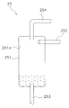
- FIG. 6 is a schematic cross-sectional view of a refrigerant storage tank in Modification 1.
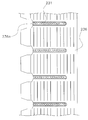
- FIG. It is an external appearance perspective view of the outdoor heat exchanger in the modification 2.
- FIG. 1 is a schematic configuration diagram of an air conditioner 1 as a refrigeration apparatus according to an embodiment of the present invention.
- the air conditioner 1 is a refrigeration apparatus capable of performing a cooling operation as a cooling operation and a heating operation as a heating operation by performing a vapor compression refrigeration cycle.
- the air conditioner 1 is mainly configured by connecting an outdoor unit 2 and an indoor unit 4.
- the outdoor unit 2 and the indoor unit 4 are connected via a liquid refrigerant communication tube 5 and a gas refrigerant communication tube 6. That is, the vapor compression refrigerant circuit 10 of the air conditioner 1 is configured by connecting the outdoor unit 2 and the indoor unit 4 via the refrigerant communication pipes 5 and 6.
- the indoor unit 4 is installed indoors and constitutes a part of the refrigerant circuit 10.
- the indoor unit 4 mainly has an indoor heat exchanger 41.
- the indoor heat exchanger 41 is a heat exchanger that functions as a refrigerant evaporator during cooling operation to cool indoor air, and functions as a refrigerant radiator during heating operation to heat indoor air.
- the liquid side of the indoor heat exchanger 41 is connected to the liquid refrigerant communication tube 5, and the gas side of the indoor heat exchanger 41 is connected to the gas refrigerant communication tube 6.
- the indoor heat exchanger 41 is a cross fin heat exchanger, and mainly includes heat transfer fins 411 and heat transfer tubes 412.
- FIG. 1 the indoor heat exchanger 41 is a cross fin heat exchanger, and mainly includes heat transfer fins 411 and heat transfer tubes 412.
- the heat transfer fins 411 are thin aluminum flat plates, and the heat transfer fins 411 have a plurality of through holes.
- the heat transfer tube 412 includes a straight tube 412a inserted into the through hole of the heat transfer fin 411, and U-shaped tubes 412b and 412c that connect ends of adjacent straight tubes 412a.
- the straight pipe 412 a is brought into close contact with the heat transfer fin 411 by being expanded after being inserted into the through hole of the heat transfer fin 411.
- the straight pipe 412a and the first U-shaped pipe 412b are integrally formed.
- the second U-shaped pipe 412c is welded or brazed after the straight pipe 412a is inserted into the through-hole of the heat transfer fin 411 and expanded. Is connected to the end of the straight pipe 411a.
- the indoor unit 4 also has an indoor fan 42 for supplying indoor air as supply air after sucking indoor air into the indoor unit 4 and exchanging heat with the refrigerant in the indoor heat exchanger 41.
- an indoor fan 42 for supplying indoor air as supply air after sucking indoor air into the indoor unit 4 and exchanging heat with the refrigerant in the indoor heat exchanger 41.
- the indoor unit 4 also has an indoor side control unit 44 that controls the operation of each part constituting the indoor unit 4.
- the indoor side control unit 44 includes a microcomputer and a memory for controlling the indoor unit 4, and exchanges control signals and the like with a remote controller (not shown). Control signals and the like can be exchanged with the unit 2 via the transmission line 8a.
- the outdoor unit 2 is installed outside and constitutes a part of the refrigerant circuit 10.
- the outdoor unit 2 mainly includes a compressor 21, a switching mechanism 22, an outdoor heat exchanger 23, a first expansion mechanism 24, a refrigerant storage tank 25, a second expansion mechanism 26, and a liquid side closing valve 27. And a gas side closing valve 28.
- the compressor 21 is a device that compresses the low-pressure refrigerant in the refrigeration cycle until the pressure becomes high.
- the compressor 21 has a hermetic structure in which a rotary type or scroll type positive displacement compression element (not shown) is rotationally driven by a compressor motor 21a controlled by an inverter.
- the compressor 21 has a suction pipe 31 connected to the suction side and a discharge pipe 32 connected to the discharge side.
- the suction pipe 31 is a refrigerant pipe that connects the suction side of the compressor 21 and the first port 22 a of the switching mechanism 22.
- the suction pipe 31 is provided with an accumulator 29.
- the discharge pipe 32 is a refrigerant pipe that connects the discharge side of the compressor 21 and the second port 22 b of the switching mechanism 22.
- the switching mechanism 22 is a mechanism for switching the direction of refrigerant flow in the refrigerant circuit 10.
- the switching mechanism 22 causes the outdoor heat exchanger 23 to function as a radiator for the refrigerant compressed in the compressor 21, and the refrigerant evaporator that has radiated the indoor heat exchanger 41 in the outdoor heat exchanger 23. Switch to function as. That is, during the cooling operation, the switching mechanism 22 switches between the second port 22b and the third port 22c and the first port 22a and the fourth port 22d. Thereby, the discharge side (here, the discharge pipe 32) of the compressor 21 and the gas side (here, the first gas refrigerant pipe 33) of the outdoor heat exchanger 23 are connected (of the switching mechanism 22 of FIG. 1).
- the suction side (here, the suction pipe 31) of the compressor 21 and the gas refrigerant communication pipe 6 side (here, the second gas refrigerant pipe 34) are connected (see the solid line of the switching mechanism 22 in FIG. 1). ).
- the switching mechanism 22 causes the outdoor heat exchanger 23 to function as an evaporator of the refrigerant that has dissipated heat in the indoor heat exchanger 41 during the heating operation, and the indoor heat exchanger 41 is used for the refrigerant compressed in the compressor 21. Switch to function as a radiator. That is, during the heating operation, the switching mechanism 22 switches the second port 22b and the fourth port 22d to communicate and the first port 22a and the third port 22c to communicate.
- the discharge side (here, the discharge pipe 32) of the compressor 21 and the gas refrigerant communication pipe 6 side (here, the second gas refrigerant pipe 34) are connected (the broken line of the switching mechanism 22 in FIG. 1). reference).
- the suction side (here, the suction pipe 31) of the compressor 21 and the gas side (here, the first gas refrigerant pipe 33) of the outdoor heat exchanger 23 are connected (broken line of the switching mechanism 22 in FIG. 1). See).
- the first gas refrigerant pipe 33 is a refrigerant pipe that connects the third port 22 c of the switching mechanism 22 and the gas side of the outdoor heat exchanger 23.
- the second gas refrigerant pipe 33 is a refrigerant pipe that connects the fourth port 22d of the switching mechanism 22 and the gas refrigerant communication pipe 6 side.
- the switching mechanism 22 is a four-way switching valve.
- the outdoor heat exchanger 23 is a heat exchanger that functions as a refrigerant radiator that uses outdoor air as a cooling source during cooling operation, and functions as a refrigerant evaporator that uses outdoor air as a heating source during heating operation.
- the outdoor heat exchanger 23 has a liquid side connected to the liquid refrigerant pipe 35 and a gas side connected to the first gas refrigerant pipe 33.
- the liquid refrigerant pipe 35 is a refrigerant pipe that connects the liquid side of the outdoor heat exchanger 23 and the liquid refrigerant communication pipe 7 side. As shown in FIG.
- the outdoor heat exchanger 23 is a stacked heat exchanger, and mainly includes a flat tube 231, a corrugated fin 232, and headers 233 a and 233 b.
- FIG. 3 is an external perspective view of the outdoor heat exchanger 23.
- the flat tube 231 is formed of aluminum or an aluminum alloy, and has a flat portion 231a serving as a heat transfer surface and a plurality of internal flow paths (not shown) through which a refrigerant flows.
- the flat tubes 231 are arranged in a plurality of stages so as to be stacked with an interval (ventilation space) in a state where the flat portion 231a is directed upward and downward.
- the corrugated fins 232 are aluminum or aluminum alloy fins bent into a corrugated shape.
- the corrugated fins 232 are arranged in a ventilation space sandwiched between upper and lower flat tubes 231, and a valley portion and a mountain portion are in contact with a flat portion 231 a of the flat tube 231.
- the trough part, the peak part, and the plane part 231a are joined by brazing or the like.
- the headers 233a and 233b are connected to both ends of the flat tubes 231 arranged in a plurality of stages in the vertical direction.
- the headers 233 a and 233 b have a function of supporting the flat tube 231, a function of guiding the refrigerant to the internal flow path of the flat tube 231, and a function of collecting the refrigerant that has come out of the internal flow path.
- the refrigerant flowing from the first inlet / outlet 234 of the first header 233a is distributed almost evenly to each internal flow path of the uppermost flat tube 231; It flows toward the second header 233b.
- the refrigerant that has reached the second header 233b is evenly distributed to each internal flow path of the second-stage flat tube 231 and flows toward the first header 233a.
- the refrigerant in the odd-numbered flat tubes 231 flows toward the second header 233b, and the refrigerant in the even-numbered flat tubes 231 flows toward the first header 233a.
- the refrigerant in the flat tube 231 at the lowest level and the even number level flows toward the first header 233a, collects at the first header 233a, and flows out from the second inlet / outlet 235 of the first header 233a.
- the outdoor heat exchanger 23 functions as a refrigerant evaporator
- the refrigerant flows in from the second inlet / outlet 235 of the first header 233a, and the flat tubes 231 and 231 in the opposite direction to the function as a refrigerant radiator. After flowing through the headers 233a and 233b, it flows out from the first entrance / exit 234 of the first header 233a.
- the refrigerant flowing in the flat tube 231 radiates heat to the airflow flowing in the ventilation space via the corrugated fins 232. Further, when the outdoor heat exchanger 23 functions as a refrigerant evaporator, the refrigerant flowing through the flat tube 231 absorbs heat from the air flow flowing through the ventilation space via the corrugated fins 232.
- the capacity of the outdoor heat exchanger 23 is smaller than the capacity of the indoor heat exchanger 41 by using the laminated heat exchanger as described above as the outdoor heat exchanger 23. This point will be described with reference to FIG. 4 using a packaged air conditioner as an example.
- FIG. 4 using a packaged air conditioner as an example.
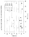
- FIG. 4 is a graph showing the outdoor heat exchanger volume / indoor heat exchanger volume ratio by capacity.
- ⁇ is a normal type of packaged air conditioner (cross fin type outdoor heat exchanger)
- ⁇ is an outdoor heat exchanger of package air conditioner small diameter type (stacked type outdoor heat exchanger)
- ⁇ is a normal type of room air conditioner ( Cross fin type outdoor heat exchanger)
- ⁇ indicates outdoor heat exchanger small diameter type (stacked type outdoor heat exchanger) of room air conditioner.
- the capacity of the laminated heat exchanger is not only smaller than the volume of the cross fin type outdoor heat exchanger, but also smaller than the capacity of the cross fin type indoor heat exchanger 41 connected thereto. Is meant to be.
- the air conditioning apparatus surplus refrigerant is generated during the cooling operation. Therefore, in the air conditioner 1, the surplus refrigerant is accommodated in the refrigerant storage tank 25.
- the refrigerant storage tank 25 that stores excess refrigerant. Even when the exchanger capacity / indoor heat exchanger volume ratio is 1.0, the use of the refrigerant storage tank 25 enables stable refrigerant control.
- the first expansion mechanism 24 is a device that functions as an upstream expansion mechanism that reduces the refrigerant radiated in the outdoor heat exchanger 23 to an intermediate pressure in the refrigeration cycle during the cooling operation.
- the second expansion mechanism 26 serving as an upstream expansion mechanism is a device that functions as a downstream expansion mechanism that depressurizes the refrigerant temporarily stored in the refrigerant storage tank 25 to a low pressure in the refrigeration cycle.
- the first expansion mechanism 24 is provided in a portion of the liquid refrigerant pipe 35 near the outdoor heat exchanger 23.
- an electric expansion valve is used as the first expansion mechanism 24.
- the second expansion mechanism 26 is a downstream expansion that depressurizes the refrigerant temporarily stored in the refrigerant storage tank 25 after being depressurized in the first expansion mechanism 24 as an upstream expansion mechanism to a low pressure in the refrigeration cycle. It is a device that functions as a mechanism.
- the second expansion mechanism 26 is a device that functions as an upstream expansion mechanism that reduces the refrigerant that has radiated heat in the indoor heat exchanger 41 to an intermediate pressure in the refrigeration cycle during heating operation.
- the second expansion mechanism 26 is provided in a portion of the liquid refrigerant pipe 35 near the liquid side closing valve 27. Here, an electric expansion valve is used as the second expansion mechanism 26.
- the refrigerant storage tank 25 is provided between the first expansion mechanism 24 and the second expansion mechanism 26, and the refrigerant depressurized by the first expansion mechanism 24 or the second expansion mechanism 26 that functions as an upstream expansion mechanism. It is a container that can be stored as surplus refrigerant. For example, the amount of liquid refrigerant that can be accommodated in the indoor heat exchanger 41 during the heating operation in which the indoor heat exchanger 41 functions as a refrigerant radiator is 1100 cc, and the outdoor heat exchanger 23 functions as a refrigerant radiator.
- the refrigerant storage tank 25 When the amount of liquid refrigerant that can be accommodated in the outdoor heat exchanger 23 during the cooling operation is 800 cc, the remaining 300 cc of liquid refrigerant that cannot be accommodated in the outdoor heat exchanger 23 during the cooling operation is stored in the refrigerant storage tank 25. Temporarily accommodated. Further, for example, the refrigerant immediately before entering the refrigerant storage tank 25 includes a gas component generated when the pressure is reduced in the first expansion mechanism 24 or the second expansion mechanism 26 that functions as the upstream expansion mechanism. For this reason, after this refrigerant enters the refrigerant storage tank 25, it is separated into a liquid component and a gas component, the liquid refrigerant is stored on the lower side, and the gas refrigerant is stored on the upper side.
- the gas refrigerant separated in the refrigerant storage tank 25 flows through the bypass pipe 30 to the suction pipe 31 of the compressor 21.
- the liquid refrigerant separated in the refrigerant storage tank 25 flows to the outdoor heat exchanger 23 after being depressurized in the second expansion mechanism 26 or the first expansion mechanism 24 that functions as an upstream side expansion mechanism.
- the bypass pipe 30 is provided so as to connect between the upper part of the refrigerant storage tank 25 and the middle part of the suction pipe 31.
- a flow rate adjusting mechanism 30a is provided in the middle of the bypass pipe 30, a flow rate adjusting mechanism 30a is provided.
- an electric expansion valve is used as the flow rate adjusting mechanism 30a.
- the outlet of the bypass pipe 30 may be directly connected to the compressor 21 instead of being connected to the middle part of the suction pipe 31.
- the liquid side shut-off valve 27 and the gas side shut-off valve 28 are valves provided at connection ports with external devices and pipes (specifically, the liquid refrigerant communication pipe 5 and the gas refrigerant communication pipe 6).
- the liquid side closing valve 26 is provided at the end of the liquid refrigerant pipe 35.
- the gas side closing valve 27 is provided at the end of the second gas refrigerant pipe 34.
- the outdoor unit 2 has an outdoor fan 36 for sucking outdoor air into the outdoor unit 2, exchanging heat with the refrigerant in the outdoor heat exchanger 23, and then discharging the air to the outside.
- a propeller fan or the like driven by an outdoor fan motor 37 is used as the outdoor fan 36.
- the outdoor unit 2 also has an outdoor control unit 38 that controls the operation of each unit constituting the outdoor unit 2.
- the outdoor side control part 38 has a microcomputer, memory, etc. for controlling the outdoor unit 2, and controls signal between the indoor side control parts 43 of the indoor unit 4 via the transmission line 8a. Etc. can be exchanged. That is, the control part 8 which performs operation control of the whole air conditioning apparatus 1 is comprised by the transmission line 8a which connects between the indoor side control part 44, the outdoor side control part 38, and the control parts 38 and 44.
- the control unit 8 can control the operation of various devices and valves 21a, 22, 24, 26, 30a, 37, 43, and the like based on various operation settings, detection values of various sensors, and the like. .
- Refrigerant communication pipes 5 and 6 are refrigerant pipes constructed on site when the air conditioner 1 is installed at an installation location such as a building, and installation conditions such as an installation location and a combination of an outdoor unit and an indoor unit. Those having various lengths and tube diameters are used.
- the refrigerant circuit 10 of the air conditioner 1 is configured by connecting the outdoor unit 2, the indoor unit 4, and the refrigerant communication pipes 5 and 6.
- the refrigerant circuit 10 includes the compressor 21, the outdoor heat exchanger 23, the first expansion mechanism 24 as the upstream expansion mechanism, the refrigerant storage tank 25, and the second expansion mechanism as the downstream expansion mechanism.
- the refrigerant circuit 10 also includes the compressor 21, the indoor heat exchanger 41, the second expansion mechanism 26 as the upstream expansion mechanism, the refrigerant storage tank 25, and the first expansion mechanism as the downstream expansion mechanism during the heating operation as the heating operation.
- a refrigeration cycle in which refrigerant flows in the order of the expansion mechanism 24 and the outdoor heat exchanger 23 is performed.
- the air conditioner 1 can perform various operations such as a cooling operation and a heating operation by the control unit 8 including the indoor side control unit 44 and the outdoor side control unit 38.
- the air conditioner 1 can perform a cooling operation and a heating operation as described above.
- cooling operation of the air conditioning apparatus 1 and heating operation is demonstrated.
- the switching mechanism 22 is switched to the state indicated by the broken line in FIG. 1, that is, the communication between the second port 22b and the fourth port 22d and the communication between the first port 22a and the third port 22c. Do.
- the low-pressure refrigerant in the refrigeration cycle is sucked into the compressor 21, compressed until it reaches a high pressure, and then discharged.
- the high-pressure refrigerant discharged from the compressor 21 is sent to the indoor heat exchanger 41 through the switching mechanism 22, the gas side closing valve 28 and the gas refrigerant communication pipe 6.
- the high-pressure refrigerant sent to the indoor heat exchanger 41 radiates heat by exchanging heat with indoor air in the indoor heat exchanger 41. Thereby, indoor air is heated.
- capacitance of the indoor heat exchanger 41 is larger than the capacity
- most liquid refrigerants are accommodated in the indoor heat exchanger 41 at the time of heating operation.
- the high-pressure refrigerant radiated by the indoor heat exchanger 41 is sent to the second expansion mechanism 26 that functions as an upstream expansion mechanism through the liquid refrigerant communication tube 5 and the liquid-side closing valve 27.
- the refrigerant sent to the second expansion mechanism 26 is depressurized to an intermediate pressure by the second expansion mechanism 26 and then sent to the refrigerant storage tank 25.
- the refrigerant immediately before entering the refrigerant storage tank 25 contains a gas component generated when the pressure is reduced in the second expansion mechanism 26, but after entering the refrigerant storage tank 25, the liquid component and the gas component are separated.
- the liquid refrigerant is stored on the lower side, and the gas refrigerant is stored on the upper side.
- the flow rate adjustment mechanism 30 a of the bypass pipe 30 is controlled to be in the open state, the gas refrigerant in the refrigerant storage tank 25 goes to the suction pipe 31 of the compressor 21 through the bypass pipe 30.
- the liquid refrigerant in the refrigerant storage tank 25 is sent to the outdoor heat exchanger 23 after being decompressed to a low pressure by the first expansion mechanism 24 as a downstream expansion mechanism.
- the low-pressure refrigerant sent to the outdoor heat exchanger 23 evaporates by exchanging heat with outdoor air supplied by the outdoor fan 36 in the outdoor heat exchanger 23. At this time, the refrigerant flowing into the outdoor heat exchanger 23 is reduced by the gas-liquid separation operation in the refrigerant storage tank 25 and the operation of sucking the gas refrigerant separated into the compressor 21 through the bypass pipe 30. . For this reason, since the flow volume of the refrigerant
- the switching mechanism 22 is in a state indicated by a solid line in FIG. 1, that is, switching between the second port 22b and the third port 22c and the first port 22a and the fourth port 22d. Do.
- the low-pressure refrigerant in the refrigeration cycle is sucked into the compressor 21, compressed until it reaches a high pressure, and then discharged.
- the high-pressure refrigerant discharged from the compressor 21 is sent to the outdoor heat exchanger 23 through the switching mechanism 22.
- the high-pressure refrigerant sent to the outdoor heat exchanger 23 radiates heat by exchanging heat with outdoor air in the outdoor heat exchanger 23.
- the high-pressure refrigerant that has dissipated heat in the outdoor heat exchanger 23 is sent to the first expansion mechanism 24 that functions as the upstream expansion mechanism, and is reduced to the intermediate pressure by the first expansion mechanism 24, and then sent to the refrigerant storage tank 25. It is done.
- the outdoor heat exchanger 23 cannot accommodate all the liquid refrigerants at the time of air_conditionaing
- the refrigerant immediately before entering the refrigerant storage tank 25 includes a gas component generated when the pressure is reduced in the first expansion mechanism 24. However, after entering the refrigerant storage tank 25, the refrigerant is separated into a liquid component and a gas component.
- the liquid refrigerant is stored on the lower side, and the gas refrigerant is stored on the upper side.
- the flow rate adjustment mechanism 30 a of the bypass pipe 30 is controlled to be in the open state, the gas refrigerant in the refrigerant storage tank 25 goes to the suction pipe 31 of the compressor 21 through the bypass pipe 30.
- the liquid refrigerant in the refrigerant storage tank 25 is depressurized to a low pressure by the second expansion mechanism 26 that functions as a downstream expansion mechanism, and then sent to the indoor heat exchanger 41 through the liquid side closing valve 27 and the liquid refrigerant communication pipe 5. .
- the low-pressure refrigerant sent to the indoor heat exchanger 41 evaporates by exchanging heat with indoor air in the indoor heat exchanger 41. Thereby, indoor air is cooled. At this time, the refrigerant flowing into the indoor heat exchanger 41 is reduced by the gas-liquid separation operation in the refrigerant storage tank 25 and the operation of sucking the gas refrigerant separated into the compressor 21 through the bypass pipe 30. . For this reason, since the flow volume of the refrigerant
- the low-pressure refrigerant evaporated in the indoor heat exchanger 51 is again sucked into the compressor 21 through the gas refrigerant communication pipe 6, the gas side shut-off valve 28, and the switching mechanism 22.
- the air conditioner 1 of the present embodiment has the following features.
- the indoor heat exchanger 41 is a cross fin heat exchanger
- the outdoor heat exchanger 23 is a stacked heat exchanger
- the volume of the outdoor heat exchanger 23 is the indoor heat exchange.
- the volume of the container 41 is 100% or less.
- a refrigerant storage tank 25 for storing the refrigerant decompressed by the upstream side expansion mechanism is provided between the other of the two.
- the surplus refrigerant that cannot be accommodated in the outdoor heat exchanger 23 during the cooling operation is accommodated in the refrigerant storage tank 25 located in the vicinity of the downstream side of the outdoor heat exchanger 23.
- the bypass pipe 30 is provided as described above.
- the bypass pipe 30 guides the gas component of the refrigerant stored in the refrigerant storage tank 25 to the compressor 21 or the suction pipe 31 of the compressor 21.
- the refrigerant decompressed in one of the first expansion mechanism 24 and the second expansion mechanism 26 as the upstream expansion mechanism is separated into a liquid component and a gas component in the refrigerant storage tank 25, and the gas component is It goes to the bypass pipe 30.
- the refrigerant that has passed through the flow rate adjustment mechanism 30 a evaporates in the indoor heat exchanger 41 and the outdoor heat exchanger 23, and then enters the compressor 21 or the suction pipe 31 of the compressor 21. It will be merged with the refrigerant.
- the flow rate adjustment mechanism 30a is an electric expansion valve, the refrigerant state immediately before being sucked into the compressor 21 can be adjusted more optimally by controlling the valve opening degree.
- the flow rate of the refrigerant returning to the compressor 21 can be increased or decreased by controlling the valve opening degree of the flow rate adjusting mechanism 30a, the circulation flow rate of the refrigerant according to the refrigeration load on the indoor heat exchanger 41 side, that is, The flow rate of the refrigerant flowing through the indoor heat exchanger 41 can be controlled.
- a container for storing the refrigerant is used as the refrigerant storage tank 25.
- the present invention is not limited to this.
- a cyclone type gas-liquid separator as shown in FIG.
- the refrigerant storage tank 25 of this modification mainly includes a cylindrical container 251, a first connection pipe 252, a second connection pipe 253, and a third connection pipe 254.
- the first connecting pipe 252 is connected in the tangential direction of the circumferential side wall of the cylindrical container 251, and communicates the inside of the cylindrical container 251 with the second expansion mechanism 26 or the first expansion mechanism 24 as a downstream side expansion mechanism. ing.
- the second connection pipe 253 is connected to the bottom wall of the cylindrical container 251 and communicates the inside of the cylindrical container 251 with the first expansion mechanism 24 or the second expansion mechanism 26 as the upstream expansion mechanism.
- the third connection pipe 254 is connected to the upper wall of the cylindrical container 251 and connects the inside of the cylindrical container 251 and the bypass pipe 30.
- the intermediate-pressure refrigerant flowing into the cylindrical container 251 through the first connection pipe 252 flows in a vortex along the inner peripheral surface 251a of the circumferential side wall of the cylindrical container 251, Liquid refrigerant adheres to the inner peripheral surface 251a, and the liquid refrigerant and the gas refrigerant are efficiently separated.
- the liquid refrigerant descends due to gravity, accumulates on the lower side, and flows out from the cylindrical container 251 through the second connection pipe 253.
- the gas refrigerant rises while turning, accumulates on the upper side, and flows out of the cylindrical container 251 through the third connection pipe 254.
- the refrigerant storage tank 25 composed of a gas-liquid separator has both a refrigerant storage function for storing liquid refrigerant and a function for separating the liquid component and the gas component. This eliminates the need for a device and contributes to the simplification of the device configuration.
- the outdoor heat exchanger 23 has illustrated the laminated heat exchanger which has the some flat tube 231 and the corrugated fin 232.
- the outdoor heat exchanger 23 is arranged such that a plurality of flat tubes 231 are stacked at intervals, and corrugated fins 232 are sandwiched between adjacent flat tubes 231.
- the outdoor heat exchanger 23 is not limited to the configuration in the above-described embodiment and the first modification.
- a stacked heat exchanger having a flat tube 231 and a fin 236 formed with a notch 236a into which the flat tube 231 is inserted may be used. Even in this case, the same effects as those of the above-described embodiment and Modification 1 can be obtained.
- the outdoor heat exchanger 23 has illustrated the laminated heat exchanger which has the some flat tube 231 and the corrugated fin 232.
- the outdoor heat exchanger 23 is arranged such that a plurality of flat tubes 231 are stacked at intervals, and corrugated fins 232 are sandwiched between adjacent flat tubes 231.
- the outdoor heat exchanger 23 is not limited to the configuration in the above embodiment and the first modification.
- the flat tube is formed in a meandering shape, and the fins are sandwiched between adjacent surfaces of the flat tube. It may be a configuration. Even in this case, the same effects as those of the above embodiment and the first and second modifications can be obtained.
- the outdoor heat exchanger 23 is a stacked heat exchanger having a plurality of flat tubes 231 and fins 236 formed with corrugated fins 232 and notches 236a. It is not limited to this.
- both the outdoor heat exchanger 23 and the indoor heat exchanger 41 are cross-fin heat exchangers, and the outdoor heat exchanger 23
- the heat transfer tube diameter may be narrower than the heat transfer tube diameter of the indoor heat exchanger 41. Even in this case, the same effects as those of the above-described embodiment and Modifications 1 to 3 can be obtained.
- the circuit portion from after passing through the first expansion mechanism 24 functioning as the downstream expansion mechanism until being sucked into the compressor 21 through the outdoor heat exchanger 23 becomes a low pressure in the refrigeration cycle.
- coolant the ether type synthetic oil which has some compatibility with R32, the mineral oil which is incompatible with R32, an alkylbenzene type synthetic oil, etc. can be considered.
- the ether synthetic oil loses the compatibility when the temperature is lowered to about ⁇ 5 ° C., and the mineral oil and the alkylbenzene synthetic oil are not compatible even at a higher temperature than the ether synthetic oil.
- the first and second expansion mechanisms 24 and 26 as the upstream expansion mechanism and the downstream expansion mechanism are provided. Since the refrigerant storage tank 25 is provided in the compressor 21, compared with the case where the refrigerant storage tank is provided on the suction side of the compressor 21, two-layer separation on the suction side of the compressor 21 is less likely to occur. It is easy to return. As described above, in the refrigeration apparatus 1 according to the present modification, the outdoor heat exchanger 23 is provided by providing the refrigerant storage tank 25 between the first and second expansion mechanisms 24 and 26 as the upstream expansion mechanism and the downstream expansion mechanism.
- the present invention is widely applicable to a refrigeration apparatus capable of performing a cooling operation and a heating operation.
- Air conditioning equipment (refrigeration equipment) DESCRIPTION OF SYMBOLS 21 Compressor 23 Outdoor heat exchanger 24, 26 Expansion mechanism 25 Refrigerant storage tank 30 Bypass pipe 30a Flow rate adjustment mechanism 41 Indoor heat exchanger
Landscapes
- Engineering & Computer Science (AREA)
- Mechanical Engineering (AREA)
- General Engineering & Computer Science (AREA)
- Thermal Sciences (AREA)
- Physics & Mathematics (AREA)
- Power Engineering (AREA)
- Chemical & Material Sciences (AREA)
- Analytical Chemistry (AREA)
- Air Conditioning Control Device (AREA)
- Other Air-Conditioning Systems (AREA)
- Compression-Type Refrigeration Machines With Reversible Cycles (AREA)
- Devices That Are Associated With Refrigeration Equipment (AREA)
- Air Filters, Heat-Exchange Apparatuses, And Housings Of Air-Conditioning Units (AREA)
Abstract
Description
本発明の課題は、冷却運転及び加熱運転を行うことが可能な冷凍装置において、室外熱交換器の容積が室内熱交換器の容積以下の場合に、冷却運転時に生じる余剰冷媒を収容できるようにすることにある。
このため、このような冷凍装置では、室外熱交換器の容量が室内熱交換器の容量よりも小さくなることによって、冷却運転時に、余剰冷媒が発生することになる。このような余剰冷媒が、気相部分を有する室内熱交換器から圧縮機の吸入側までの部分に過剰に行き渡ると、冷媒制御に支障をきたすおそれがある。
これにより、この冷凍装置では、気相部分を有する室内熱交換器から圧縮機の吸入側までの部分に過剰に行き渡ることを防ぐことができるようになるため、冷媒制御に支障をきたすことを防止することができる。
そこで、ここでは、上流側膨張機構と下流側膨張機構との間に上流側膨張機構によって減圧された冷媒を貯留する冷媒貯留タンクを設けることによって、冷却運転時に室外熱交換器で収容しきなくなった余剰冷媒を、室外熱交換器の下流側近傍に位置する冷媒貯留タンクに収容するようにしている。
これにより、この冷凍装置では、気相部分を有する室内熱交換器から圧縮機の吸入側までの部分に過剰に行き渡ることを防ぐことができるようになるため、冷媒制御に支障をきたすことを防止することができる。
冷凍装置において冷媒としてR32を使用すると、低温条件においては、圧縮機の潤滑のために冷媒とともに封入されている冷凍機油の溶解度が非常に小さくなる傾向がある。このため、冷凍サイクルにおける低圧になると、冷媒温度の低下によって、冷凍機油の溶解度が大きく低下することになる。ここで、例えば、圧縮機の吸入側に冷媒貯留タンクを有する従来の冷凍装置において、冷媒としてR32を使用すると、冷凍サイクルにおける低圧になる冷媒貯留タンク内で冷媒と冷凍機油が二層分離し、圧縮機に冷凍機油が戻りにくくなる。
しかし、この冷凍装置では、上記のように、上流側膨張機構と下流側膨張機構との間に冷媒貯留タンクを設けているため、圧縮機の吸入側に冷媒貯留タンクを設ける場合に比べて、圧縮機に冷凍機油が戻りやすくなっている。
この冷凍装置では、上記の第1~第3の観点にかかる冷凍装置と同様に、室外熱交換器の容量が室内熱交換器の容量以下になるため、冷凍装置内の冷媒量が低減される。尚、この冷凍装置では、冷却運転時に余剰冷媒が発生するが、この余剰冷媒を冷媒貯留タンクに収容することができるため、冷媒制御に支障をきたすことを防止することができる。
この冷凍装置では、上記の第1~第3の観点にかかる冷凍装置と同様に、室外熱交換器の容量が室内熱交換器の容量以下になるため、冷凍装置内の冷媒量が低減される。尚、この冷凍装置では、冷却運転時に余剰冷媒が発生するが、この余剰冷媒を冷媒貯留タンクに収容することができるため、冷媒制御に支障をきたすことを防止することができる。
冷凍装置において冷媒としてR32を使用すると、低温条件においては、圧縮機の潤滑のために冷媒とともに封入されている冷凍機油の溶解度が非常に小さくなる傾向がある。このため、冷凍サイクルにおける低圧になると、冷媒温度の低下によって、冷凍機油の溶解度が大きく低下することになる。ここで、例えば、圧縮機の吸入側に冷媒貯留タンクを有する従来の冷凍装置において、冷媒としてR32を使用すると、冷凍サイクルにおける低圧になる冷媒貯留タンク内で冷媒と冷凍機油が二層分離し、圧縮機に冷凍機油が戻りにくくなる。
このように、この冷凍装置では、上流側膨張機構と下流側膨張機構との間に冷媒貯留タンクを設けることによって、室外熱交換器の容積が室内熱交換器の容積以下にすることによって生じる余剰冷媒の問題だけでなく、冷媒としてR32を使用することによって生じる圧縮機への油戻しの問題を解消することができる。
この冷凍装置では、上流側膨張機構において減圧された冷媒が、冷媒貯留タンクにおいて液成分とガス成分とに分離され、ガス成分はバイパス管へ向うことになる。
これにより、この冷凍装置では、加熱運転時に、蒸発に寄与しないガス成分が冷媒の蒸発器として機能する室外熱交換器に流入しなくなるため、その分だけ、冷媒の蒸発器として機能する室外熱交換器を流れる冷媒の流量を減少させることができ、冷凍サイクルにおける減圧ロスを低減することができる。
圧縮機の運転周波数が高い場合には、冷媒貯留タンクから気液二相状態の冷媒がバイパス管を通じて圧縮機または圧縮機の吸入管に戻り、圧縮機に吸入されるおそれがある。
しかし、この冷凍装置では、バイパス管に流量調整機構が設けられているため、気液二相状態の冷媒の液成分が減圧されて蒸発することになる。
これにより、この冷凍装置では、圧縮機又は圧縮機の吸入管に液成分が戻ることを防止することができる。
また、この冷凍装置では、加熱運転時に、流量調整機構を通過した冷媒が、室外熱交換器において蒸発した後に、圧縮機又は圧縮機の吸入管に向う冷媒に合流することになる。このとき、流量調整機構が電動膨張弁である場合には、弁開度を制御することによって、圧縮機に吸入される直前の冷媒状態を、より最適に調整することができる。しかも、流量調整機構の弁開度を制御することによって、圧縮機に戻る冷媒の流量を増減させることができるため、室内熱交換器側の冷凍負荷に応じて冷媒の循環流量、すなわち、室内熱交換器を流れる冷媒の流量を制御することができる。
この冷凍装置では、気液分離器からなる冷媒貯留タンクが、液成分を溜める機能、及び、液成分とガス成分とを分離する機能の両方を担うことになる。
これにより、この冷凍装置では、冷媒貯留機能を有する機器と気液分離機能を有する機器とを併設する必要がなくなるため、装置構成の簡素化に寄与する。
図1は、本発明の一実施形態にかかる冷凍装置としての空気調和装置1の概略構成図である。
空気調和装置1は、蒸気圧縮式の冷凍サイクルを行うことによって、冷却運転としての冷房運転及び加熱運転としての暖房運転を行うことが可能な冷凍装置である。空気調和装置1は、主として、室外ユニット2と、室内ユニット4とが接続されることによって構成されている。ここで、室外ユニット2と室内ユニット4とは、液冷媒連絡管5及びガス冷媒連絡管6を介して接続されている。すなわち、空気調和装置1の蒸気圧縮式の冷媒回路10は、室外ユニット2と、室内ユニット4とが冷媒連絡管5、6を介して接続されることによって構成されている。
室内ユニット4は、室内に設置されており、冷媒回路10の一部を構成している。室内ユニット4は、主として、室内熱交換器41を有している。
室内熱交換器41は、冷房運転時には冷媒の蒸発器として機能して室内空気を冷却し、暖房運転時には冷媒の放熱器として機能して室内空気を加熱する熱交換器である。室内熱交換器41の液側は液冷媒連絡管5に接続されており、室内熱交換器41のガス側はガス冷媒連絡管6に接続されている。
室内熱交換器41は、図2に示すように、クロスフィン型熱交換器であり、主として、伝熱フィン411と、伝熱管412とを有している。ここで、図2は、室内熱交換器41の正面図である。伝熱フィン411は、薄いアルミニウム製の平板であり、伝熱フィン411には、複数の貫通孔が形成されている。伝熱管412は、伝熱フィン411の貫通孔に挿入される直管412aと、隣り合う直管412aの端部同士を連結するU字管412b、412cとを有している。直管412aは、伝熱フィン411の貫通孔に挿入された後に拡管加工されることによって、伝熱フィン411と密着させられている。直管412aと第1U字管412bとは一体に形成されており、第2U字管412cは、直管412aが伝熱フィン411の貫通孔に挿入され拡管加工された後に、溶接やろう付け等によって直管411aの端部に連結されている。
また、室内ユニット4は、室内ユニット4を構成する各部の動作を制御する室内側制御部44を有している。そして、室内側制御部44は、室内ユニット4の制御を行うためのマイクロコンピュータやメモリ等を有しており、リモートコントローラ(図示せず)との間で制御信号等のやりとりを行ったり、室外ユニット2との間で伝送線8aを介して制御信号等のやりとりを行うことができるようになっている。
室外ユニット2は、室外に設置されており、冷媒回路10の一部を構成している。室外ユニット2は、主として、圧縮機21と、切換機構22と、室外熱交換器23と、第1膨張機構24と、冷媒貯留タンク25と、第2膨張機構26と、液側閉鎖弁27と、ガス側閉鎖弁28とを有している。
切換機構22は、冷媒回路10における冷媒の流れの方向を切り換えるための機構である。切換機構22は、冷房運転時には、室外熱交換器23を圧縮機21において圧縮された冷媒の放熱器として機能させ、かつ、室内熱交換器41を室外熱交換器23において放熱した冷媒の蒸発器として機能させる切り換えを行う。すなわち、切換機構22は、冷房運転時には、第2ポート22bと第3ポート22cとを連通させ、かつ、第1ポート22aと第4ポート22dとを連通させる切り換えを行う。これにより、圧縮機21の吐出側(ここでは、吐出管32)と室外熱交換器23のガス側(ここでは、第1ガス冷媒管33)とが接続される(図1の切換機構22の実線を参照)。しかも、圧縮機21の吸入側(ここでは、吸入管31)とガス冷媒連絡管6側(ここでは、第2ガス冷媒管34)とが接続される(図1の切換機構22の実線を参照)。また、切換機構22は、暖房運転時には、室外熱交換器23を室内熱交換器41において放熱した冷媒の蒸発器として機能させ、かつ、室内熱交換器41を圧縮機21において圧縮された冷媒の放熱器として機能させる切り換えを行う。すなわち、切換機構22は、暖房運転時には、第2ポート22bと第4ポート22dとを連通させ、かつ、第1ポート22aと第3ポート22cとを連通させる切り換えを行う。これにより、圧縮機21の吐出側(ここでは、吐出管32)とガス冷媒連絡管6側(ここでは、第2ガス冷媒管34)とが接続される(図1の切換機構22の破線を参照)。しかも、圧縮機21の吸入側(ここでは、吸入管31)と室外熱交換器23のガス側(ここでは、第1ガス冷媒管33)とが接続される(図1の切換機構22の破線を参照)。第1ガス冷媒管33は、切換機構22の第3ポート22cと室外熱交換器23のガス側とを接続する冷媒管である。第2ガス冷媒管33は、切換機構22の第4ポート22dとガス冷媒連絡管6側とを接続する冷媒管である。切換機構22は、ここでは、四路切換弁である。
室外熱交換器23は、図3に示すように、積層型熱交換器であり、主として、扁平管231と、波形フィン232と、ヘッダ233a、233bとを有している。ここで、図3は、室外熱交換器23の外観斜視図である。扁平管231は、アルミニウムまたはアルミニウム合金で成形されており、伝熱面となる平面部231aと、冷媒が流れる複数の内部流路(図示せず)を有している。扁平管231は、平面部231aを上下に向けた状態で間隔(通風空間)を空けて積み重なるように複数段配列されている。波形フィン232は、波形に折り曲げられたアルミニウム製またはアルミニウム合金製のフィンである。波形フィン232は、上下に隣接する扁平管231に挟まれた通風空間に配置され、谷部および山部が扁平管231の平面部231aと接触している。なお、谷部と山部と平面部231aとはロウ付け等によって接合されている。ヘッダ233a、233bは、上下方向に複数段配列された扁平管231の両端に連結されている。ヘッダ233a、233bは、扁平管231を支持する機能と、冷媒を扁平管231の内部流路に導く機能と、内部流路から出てきた冷媒を集合させる機能とを有している。室外熱交換器23が冷媒の放熱器として機能する場合には、第1ヘッダ233aの第1出入口234から流入した冷媒は、最上段の扁平管231の各内部流路へほぼ均等に分配され、第2ヘッダ233bに向って流れる。第2ヘッダ233bに達した冷媒は、2段目の扁平管231の各内部流路へ均等に分配され第1ヘッダ233aへ向って流れる。以降、奇数段目の扁平管231内の冷媒は、第2ヘッダ233bへ向って流れ、偶数段目の扁平管231内の冷媒は、第1ヘッダ233aに向って流れる。そして、最下段で且つ偶数段目の扁平管231内の冷媒は、第1ヘッダ233aに向って流れ、第1ヘッダ233aで集合して、第1ヘッダ233aの第2出入口235から流出する。室外熱交換器23が冷媒の蒸発器として機能する場合には、第1ヘッダ233aの第2出入口235から冷媒が流入して、冷媒の放熱器として機能する場合とは逆方向に扁平管231及びヘッダ233a、233bを流れた後に、第1ヘッダ233aの第1出入口234から流出する。そして、室外熱交換器23が冷媒の放熱器として機能する場合には、扁平管231内を流れる冷媒は、波形フィン232を介して通風空間を流れる空気流に放熱する。また、室外熱交換器23が冷媒の蒸発器として機能する場合には、扁平管231内を流れる冷媒は、波形フィン232を介して通風空間を流れる空気流から吸熱する。ここでは、室外熱交換器23として、上記のような積層型熱交換器を使用することによって、室外熱交換器23の容量が、室内熱交換器41の容量よりも小さくなっている。この点に関して、パッケージエアコンを例に挙げて、図4を用いて説明する。ここで、図4は、室外熱交換器容積/室内熱交換器容積比を能力別に表したグラフである。図4において、◇はパッケージエアコンの通常タイプ(クロスフィン型室外熱交換器)、◆はパッケージエアコンの室外熱交換器細径タイプ(積層型室外熱交換器)、△はルームエアコンの通常タイプ(クロスフィン型室外熱交換器)、▲はルームエアコンの室外熱交換器細径タイプ(積層型室外熱交換器)を示している。図4によれば、室外熱交換器と室内熱交換器とがともにクロスフィン型熱交換器である場合に対して、室外熱交換器だけを同等の熱交換性能を有する積層型熱交換器に変更した場合には、室外熱交換器容量/室内熱交換器容積比が1.0を下回っている。これは、積層型熱交換器の容量がクロスフィン型の室外熱交換器の容積に比べて小さくなるだけでなく、これに接続されているクロスフィン型の室内熱交換器41の容量よりも小さくなることを意味している。このため、空気調和装置1では、冷房運転時に余剰冷媒が発生することになる。そこで、空気調和装置1では、その余剰冷媒を冷媒貯留タンク25に収容するようにしている。尚、図4によれば、室外熱交換器容量/室内熱交換器容積比が0.3~0.9のときに、余剰冷媒を収容する冷媒貯留タンク25を用いることが好ましいが、室外熱交換器容量/室内熱交換器容積比が1.0の場合でも冷媒貯留タンク25を用いることによって、安定した冷媒制御が可能になる。
第2膨張機構26は、冷房運転時には、上流側膨張機構としての第1膨張機構24において減圧された後に冷媒貯留タンク25に一時的に貯留された冷媒を冷凍サイクルにおける低圧まで減圧する下流側膨張機構として機能する機器である。また、第2膨張機構26は、暖房運転時には、室内熱交換器41において放熱した冷媒を冷凍サイクルにおける中間圧まで減圧する上流側膨張機構として機能する機器である。第2膨張機構26は、液冷媒管35の液側閉鎖弁27寄りの部分に設けられている。ここでは、第2膨張機構26として、電動膨張弁が使用されている。
また、室外ユニット2は、室外ユニット2内に室外空気を吸入して、室外熱交換器23において冷媒と熱交換させた後に、外部に排出するための室外ファン36を有している。ここでは、室外ファン36として、室外ファンモータ37によって駆動されるプロペラファン等が使用されている。
また、室外ユニット2は、室外ユニット2を構成する各部の動作を制御する室外側制御部38を有している。そして、室外側制御部38は、室外ユニット2の制御を行うためのマイクロコンピュータやメモリ等を有しており、室内ユニット4の室内側制御部43との間で伝送線8aを介して制御信号等のやりとりを行うことができるようになっている。すなわち、室内側制御部44と室外側制御部38と制御部38、44間を接続する伝送線8aとによって、空気調和装置1全体の運転制御を行う制御部8が構成されている。
冷媒連絡配管5、6は、空気調和装置1を建物等の設置場所に設置する際に、現地にて施工される冷媒管であり、設置場所や室外ユニットと室内ユニットとの組み合わせ等の設置条件に応じて種々の長さや管径を有するものが使用される。
以上のように、室外ユニット2と、室内ユニット4と、冷媒連絡管5、6とが接続されることによって、空気調和装置1の冷媒回路10が構成されている。冷媒回路10は、冷却運転としての冷房運転時に、圧縮機21、室外熱交換器23、上流側膨張機構としての第1膨張機構24、冷媒貯留タンク25、下流側膨張機構としての第2膨張機構26、及び、室内熱交換器41の順に冷媒が流れる冷凍サイクルを行うようになっている。また、冷媒回路10は、加熱運転としての暖房運転時に、圧縮機21、室内熱交換器41、上流側膨張機構としての第2膨張機構26、冷媒貯留タンク25、下流側膨張機構としての第1膨張機構24、及び、室外熱交換器23の順に冷媒が流れる冷凍サイクルを行うようになっている。そして、空気調和装置1は、室内側制御部44と室外側制御部38とから構成される制御部8によって、冷房運転及び暖房運転等の各種運転を行うことができるようになっている。
空気調和装置1は、上記のように、冷房運転、及び、暖房運転を行うことができる。以下、空気調和装置1の冷房運転時及び暖房運転時の動作について説明する。
暖房運転時には、切換機構22が図1の破線で示される状態、すなわち、第2ポート22bと第4ポート22dとを連通させ、かつ、第1ポート22aと第3ポート22cとを連通させる切り換えを行う。
この冷媒回路10において、冷凍サイクルにおける低圧の冷媒は、圧縮機21に吸入され、高圧になるまで圧縮された後に吐出される。
圧縮機21から吐出された高圧の冷媒は、切換機構22、ガス側閉鎖弁28及びガス冷媒連絡管6を通じて、室内熱交換器41に送られる。
室内熱交換器41で放熱した高圧の冷媒は、液冷媒連絡管5及び液側閉鎖弁27を通じて、上流側膨張機構として機能する第2膨張機構26に送られる。
第2膨張機構26に送られた冷媒は、第2膨張機構26によって中間圧まで減圧され、その後、冷媒貯留タンク25に送られる。冷媒貯留タンク25に入る直前の冷媒には、第2膨張機構26において減圧される際に発生したガス成分が含まれているが、冷媒貯留タンク25に入った後、液成分とガス成分とに分離され、下部側に液冷媒が貯留され、上部側にガス冷媒が貯留される。そして、このとき、バイパス管30の流量調整機構30aが開状態に制御されるため、冷媒貯留タンク25のガス冷媒は、バイパス管30を通じて圧縮機21の吸入管31へ向う。冷媒貯留タンク25の液冷媒は、下流側膨張機構として第1膨張機構24によって低圧まで減圧された後に、室外熱交換器23に送られる。
室外熱交換器23で蒸発した低圧の冷媒は、切換機構22を通じて、再び、圧縮機21に吸入される。
冷房運転時には、切換機構22が図1の実線で示される状態、すなわち、第2ポート22bと第3ポート22cとを連通させ、かつ、第1ポート22aと第4ポート22dとを連通させる切り換えを行う。
圧縮機21から吐出された高圧の冷媒は、切換機構22を通じて、室外熱交換器23に送られる。
室外熱交換器23に送られた高圧の冷媒は、室外熱交換器23において、室外空気と熱交換を行って放熱する。
室外熱交換器23において放熱した高圧の冷媒は、上流側膨張機構として機能する第1膨張機構24に送られて、第1膨張機構24によって中間圧まで減圧され、その後、冷媒貯留タンク25に送られる。ここで、室外熱交換器23の容量は、室内熱交換器41の容量以下であるため、冷房運転時においては、室外熱交換器23が全ての液冷媒を収容することができない。このため、室外熱交換器23に収容しきれない液冷媒は冷媒貯留タンク25に溜まり、冷媒貯留タンク25は液冷媒で満たされる。冷媒貯留タンク25に入る直前の冷媒には、第1膨張機構24において減圧される際に発生したガス成分が含まれているが、冷媒貯留タンク25に入った後、液成分とガス成分とに分離され、下部側に液冷媒が貯留され、上部側にガス冷媒が貯留される。そして、このとき、バイパス管30の流量調整機構30aが開状態に制御されるため、冷媒貯留タンク25のガス冷媒は、バイパス管30を通じて圧縮機21の吸入管31へ向う。冷媒貯留タンク25の液冷媒は、下流側膨張機構として機能する第2膨張機構26によって低圧まで減圧された後に、液側閉鎖弁27及び液冷媒連絡管5を通じて、室内熱交換器41に送られる。
室内熱交換器51において蒸発した低圧の冷媒は、ガス冷媒連絡管6、ガス側閉鎖弁28及び切換機構22を通じて、再び、圧縮機21に吸入される。
本実施形態の空気調和装置1には、以下のような特徴がある。
空気調和装置1では、上記のように、室内熱交換器41がクロスフィン型熱交換器、室外熱交換器23が積層型熱交換器であり、室外熱交換器23の容積が、室内熱交換器41の容積の100%以下である。
このため、空気調和装置1では、冷却運転としての冷房運転時に、余剰冷媒が発生することになる。このような余剰冷媒が、気相部分を有する室内熱交換器41から圧縮機21の吸入側までの部分に過剰に行き渡ると、冷媒制御に支障をきたすおそれがある。
そこで、空気調和装置1では、上記のように、上流側膨張機構としての第1膨張機構24及び第2膨張機構26の一方と下流側膨張機構としての第1膨張機構24及び第2膨張機構26の他方との間に、上流側膨張機構によって減圧された冷媒を貯留する冷媒貯留タンク25を設けるようにしている。そして、空気調和装置1では、冷房運転時に室外熱交換器23で収容しきなくなった余剰冷媒を、室外熱交換器23の下流側近傍に位置する冷媒貯留タンク25に収容するようにしている。
空気調和装置1では、上記のように、バイパス管30が設けられている。バイパス管30は、冷媒貯留タンク25内に溜まる冷媒のガス成分を圧縮機21又は圧縮機21の吸入管31に導くようになっている。
空気調和装置1では、上流側膨張機構としての第1膨張機構24及び第2膨張機構26の一方において減圧された冷媒が、冷媒貯留タンク25において液成分とガス成分とに分離され、ガス成分はバイパス管30へ向うことになる。
圧縮機21の運転周波数が高い場合には、冷媒貯留タンク25から気液二相状態の冷媒がバイパス管30を通じて圧縮機21または圧縮機21の吸入管31に戻り、圧縮機21に吸入されるおそれがある。
しかし、空気調和装置1では、バイパス管30に流量調整機構30aが設けられているため、気液二相状態の冷媒の液成分が減圧されて蒸発することになる。
また、空気調和装置1では、暖房運転時に、流量調整機構30aを通過した冷媒が、室内熱交換器41や室外熱交換器23において蒸発した後に、圧縮機21又は圧縮機21の吸入管31に向う冷媒に合流することになる。このとき、流量調整機構30aが電動膨張弁である場合には、弁開度を制御することによって、圧縮機21に吸入される直前の冷媒状態を、より最適に調整することができる。しかも、流量調整機構30aの弁開度を制御することによって、圧縮機21に戻る冷媒の流量を増減させることができるため、室内熱交換器41側の冷凍負荷に応じて冷媒の循環流量、すなわち、室内熱交換器41を流れる冷媒の流量を制御することができる。
上記実施形態では、冷媒貯留タンク25として冷媒を貯留する容器を採用しているが、これに限定されず、例えば、図5に示すようなサイクロン方式の気液分離器を採用してもよい。
本変形例の冷媒貯留タンク25は、主として、円筒容器251、第1接続管252、第2接続管253、及び、第3接続管254を有している。
第1接続管252は、円筒容器251の円周側壁の接線方向に連結されており、円筒容器251の内部と下流側膨張機構としての第2膨張機構26又は第1膨張機構24とを連絡している。第2接続管253は、円筒容器251の底壁に連結されており、円筒容器251の内部と上流側膨張機構としての第1膨張機構24又は第2膨張機構26とを連絡している。第3接続管254は、円筒容器251の上壁に連結されており、円筒容器251の内部とバイパス管30とを連絡している。
液冷媒は重力によって降下して、下部側に溜まり、第2接続管253を通じて円筒容器251から流出する。他方、ガス冷媒は旋回しながら上昇して、上部側に溜まり、第3接続管254を通じて円筒容器251から流出する。
以上のように、本変形例では、冷媒貯留タンク25として、サイクロン方式の気液分離器を採用しているため、気液分離を効率よく行うことができる。また、気液分離器からなる冷媒貯留タンク25が液冷媒を溜める冷媒貯留機能、及び、液成分とガス成分とを分離する機能の両方を担っており、これにより、冷媒貯留容器と気液分離器とを併設する必要がなくなるため、装置構成の簡略化に寄与する。
上記実施形態及び変形例1では、室外熱交換器23が複数の扁平管231と波形フィン232とを有する積層型熱交換器が例示されている。この室外熱交換器23は、複数の扁平管231が間隔をあけて積み重なるように配列され、波形フィン232が隣接する扁平管231に挟まれている。
しかし、室外熱交換器23は、上記実施形態及び変形例1における構成に限定されることはなく、例えば、図6及び図7に示すように、間隔を空けて積み重なるように配列された複数の扁平管231と、扁平管231が差し込まれる切り欠き236aが形成されたフィン236と、を有する積層型熱交換器であってもよい。
この場合においても、上記実施形態及び変形例1と同様の作用効果を得ることができる。
上記実施形態及び変形例1では、室外熱交換器23が複数の扁平管231と波形フィン232とを有する積層型熱交換器が例示されている。この室外熱交換器23は、複数の扁平管231が間隔をあけて積み重なるように配列され、波形フィン232が隣接する扁平管231に挟まれている。
しかし、室外熱交換器23は、上記実施形態及び変形例1における構成に限定されることはなく、例えば、扁平管が蛇行形状に成形され、フィンが扁平管の互いに隣接する面の間に挟まれている構成であってもよい。
この場合においても、上記実施形態及び変形例1、2と同様の作用効果を得ることができる。
上記実施形態及び変形例1~3では、室外熱交換器23が複数の扁平管231と、波形フィン232や切り欠き236aが形成されたフィン236と、を有する積層型熱交換器であるが、これに限定されるものではない。例えば、冷房運転時に室外熱交換器23を水で冷却するような冷凍装置の場合、室外熱交換器23および室内熱交換器41がともにクロスフィン型熱交換器であって、室外熱交換器23の伝熱管径が室内熱交換器41の伝熱管径よりも細い構成であってもよい。
この場合においても、上記実施形態及び変形例1~3と同様の作用効果を得ることができる。
上記実施形態及び変形例1~4では、冷媒回路10に封入される冷媒として、種々の冷媒を使用することが可能であるが、例えば、その一種として、HFC系冷媒の一種であるR32を使用することが考えられる。
このように、本変形例の冷凍装置1では、上流側膨張機構及び下流側膨張機構としての第1及び第2膨張機構24、26間に冷媒貯留タンク25を設けることによって、室外熱交換器23として積層型熱交換器を使用する等によって室外熱交換器23の容積が室内熱交換器41の容積以下にすることによって生じる余剰冷媒の問題だけでなく、冷媒としてR32を使用することによって生じる圧縮機21への油戻しの問題を解消することができる。
21 圧縮機
23 室外熱交換器
24、26 膨張機構
25 冷媒貯留タンク
30 バイパス管
30a 流量調整機構
41 室内熱交換器
Claims (11)
- 冷却運転時に圧縮機(21)、室外熱交換器(23)、膨張機構(24、26)及び室内熱交換器(41)の順に冷媒が流れ、加熱運転時に前記圧縮機、前記室内熱交換器、前記膨張機構及び前記室外熱交換器の順に冷媒が流れる冷凍装置において、
前記室内熱交換器がクロスフィン型熱交換器、前記室外熱交換器が積層型熱交換器であり、
前記膨張機構は、冷媒を減圧する上流側膨張機構と、前記上流側膨張機構において減圧された冷媒を減圧する下流側膨張機構とを有しており、
前記上流側膨張機構と前記下流側膨張機構との間には、前記上流側膨張機構によって減圧された冷媒を貯留する冷媒貯留タンク(25)が設けられている、
冷凍装置(1)。 - 冷却運転時に圧縮機(21)、室外熱交換器(23)、膨張機構(24、26)及び室内熱交換器(41)の順に冷媒が流れ、加熱運転時に前記圧縮機、前記室内熱交換器、前記膨張機構及び前記室外熱交換器の順に冷媒が流れる冷凍装置において、
前記室外熱交換器の容積は、前記室内熱交換器の容積の100%以下であり、
前記膨張機構は、冷媒を減圧する上流側膨張機構と、前記上流側膨張機構において減圧された冷媒を減圧する下流側膨張機構とを有しており、
前記上流側膨張機構と前記下流側膨張機構との間には、前記上流側膨張機構によって減圧された冷媒を貯留する冷媒貯留タンク(25)が設けられている、
冷凍装置(1)。 - 冷媒は、R32である、
請求項1又は2に記載の冷凍装置(1)。 - 前記室外熱交換器(23)は、間隔を空けて積み重なるように配列された複数の扁平管と、隣接する前記扁平管に挟まれたフィンと、を有する積層型熱交換器である、
請求項1~3のいずれか1項に記載の冷凍装置(1)。 - 前記室外熱交換器(23)は、間隔を空けて積み重なるように配列された複数の扁平管と、前記扁平管が差し込まれる切り欠きが形成されたフィンと、を有する積層型熱交換器である、
請求項1~3のいずれか1項に記載の冷凍装置(1)。 - 前記室外熱交換器(23)は、蛇行形状に成形された扁平管と、前記扁平管の互いに隣接する面の間に挟まれたフィンと、を有する積層型熱交換器である、
請求項1~3のいずれか1項に記載の冷凍装置(1)。 - 冷媒は、R32である、
請求項2に記載の冷凍装置(1)。 - 前記室外熱交換器(23)及び前記室内熱交換器(41)は、クロスフィン型熱交換器であり、
前記室外熱交換器の伝熱管径は、前記室内熱交換器の伝熱管径よりも細く設定されている、
請求項2又は7に記載の冷凍装置(1)。 - 前記冷媒貯留タンク(25)内に溜まる冷媒のガス成分を前記圧縮機(21)又は前記圧縮機の吸入側の冷媒管に導くバイパス管(30)がさらに設けられている、
請求項1~8のいずれか1項に記載の冷凍装置(1)。 - 前記バイパス管(30)は、流量調整機構(30a)を有する、
請求項9に記載の冷凍装置(1)。 - 前記冷媒貯留タンク(25)は、気液分離器である、
請求項1~10のいずれか1項に記載の冷凍装置(1)。
Priority Applications (7)
| Application Number | Priority Date | Filing Date | Title |
|---|---|---|---|
| US14/366,251 US20140360223A1 (en) | 2011-12-20 | 2012-12-19 | Refrigeration apparatus |
| BR112014014557-1A BR112014014557B1 (pt) | 2011-12-20 | 2012-12-19 | Aparelho de refrigeração |
| AU2012354761A AU2012354761B2 (en) | 2011-12-20 | 2012-12-19 | Refrigeration apparatus |
| ES12859176T ES2797450T3 (es) | 2011-12-20 | 2012-12-19 | Dispositivo de refrigeración |
| EP12859176.5A EP2801770B1 (en) | 2011-12-20 | 2012-12-19 | Refrigeration device |
| CN201280062572.1A CN103998875B (zh) | 2011-12-20 | 2012-12-19 | 制冷装置 |
| KR1020147019771A KR101452690B1 (ko) | 2011-12-20 | 2012-12-19 | 냉동 장치 |
Applications Claiming Priority (4)
| Application Number | Priority Date | Filing Date | Title |
|---|---|---|---|
| JP2011278427 | 2011-12-20 | ||
| JP2011-278427 | 2011-12-20 | ||
| JP2012074660A JP5403095B2 (ja) | 2011-12-20 | 2012-03-28 | 冷凍装置 |
| JP2012-074660 | 2012-03-28 |
Publications (1)
| Publication Number | Publication Date |
|---|---|
| WO2013094638A1 true WO2013094638A1 (ja) | 2013-06-27 |
Family
ID=48668522
Family Applications (1)
| Application Number | Title | Priority Date | Filing Date |
|---|---|---|---|
| PCT/JP2012/082912 Ceased WO2013094638A1 (ja) | 2011-12-20 | 2012-12-19 | 冷凍装置 |
Country Status (9)
| Country | Link |
|---|---|
| US (1) | US20140360223A1 (ja) |
| EP (1) | EP2801770B1 (ja) |
| JP (1) | JP5403095B2 (ja) |
| KR (1) | KR101452690B1 (ja) |
| CN (1) | CN103998875B (ja) |
| AU (1) | AU2012354761B2 (ja) |
| BR (1) | BR112014014557B1 (ja) |
| ES (1) | ES2797450T3 (ja) |
| WO (1) | WO2013094638A1 (ja) |
Families Citing this family (7)
| Publication number | Priority date | Publication date | Assignee | Title |
|---|---|---|---|---|
| JP5858022B2 (ja) * | 2013-10-24 | 2016-02-10 | ダイキン工業株式会社 | 空気調和装置 |
| CN105940276A (zh) * | 2014-01-23 | 2016-09-14 | 三菱电机株式会社 | 热泵装置 |
| CN111164355B (zh) * | 2017-10-10 | 2024-01-05 | 三菱电机株式会社 | 空调装置 |
| US11280529B2 (en) * | 2019-06-10 | 2022-03-22 | Trane International Inc. | Refrigerant volume control |
| JP2021055958A (ja) * | 2019-09-30 | 2021-04-08 | ダイキン工業株式会社 | 冷凍装置 |
| JP6828790B1 (ja) * | 2019-10-31 | 2021-02-10 | ダイキン工業株式会社 | 冷凍装置 |
| JP7372556B2 (ja) | 2021-09-30 | 2023-11-01 | ダイキン工業株式会社 | 冷媒容器および冷凍サイクル装置 |
Citations (5)
| Publication number | Priority date | Publication date | Assignee | Title |
|---|---|---|---|---|
| JPS6143991A (ja) | 1984-07-11 | 1986-03-03 | Takeda Chem Ind Ltd | B型肝炎ウイルス表面抗原およびその製造法 |
| JPH08233378A (ja) * | 1994-11-29 | 1996-09-13 | Sanyo Electric Co Ltd | 空気調和機 |
| JPH10332212A (ja) * | 1997-06-02 | 1998-12-15 | Toshiba Corp | 空気調和装置の冷凍サイクル |
| JP2008089292A (ja) * | 2006-09-07 | 2008-04-17 | Daikin Ind Ltd | 空気調和装置 |
| JP2009299961A (ja) * | 2008-06-11 | 2009-12-24 | Daikin Ind Ltd | 冷凍装置、冷媒回収方法、および圧縮機交換方法 |
Family Cites Families (7)
| Publication number | Priority date | Publication date | Assignee | Title |
|---|---|---|---|---|
| US5111876A (en) * | 1991-10-31 | 1992-05-12 | Carrier Corporation | Heat exchanger plate fin |
| JP2001248922A (ja) * | 1999-12-28 | 2001-09-14 | Daikin Ind Ltd | 冷凍装置 |
| JP4811204B2 (ja) * | 2006-09-11 | 2011-11-09 | ダイキン工業株式会社 | 冷凍装置 |
| DK1974171T3 (da) * | 2006-09-29 | 2014-08-18 | Carrier Corp | Kompressionssystem til kølemiddeldamp med flash tank modtager |
| JP4856044B2 (ja) * | 2007-10-17 | 2012-01-18 | シャープ株式会社 | 熱交換器 |
| EP2075519B1 (en) * | 2007-12-26 | 2017-11-15 | LG Electronics Inc. | Air Conditoning system |
| CN201196506Y (zh) * | 2008-04-22 | 2009-02-18 | 陈灿 | 一种制暖系统的冷媒与制冷系统分离的空调装置 |
-
2012
- 2012-03-28 JP JP2012074660A patent/JP5403095B2/ja active Active
- 2012-12-19 ES ES12859176T patent/ES2797450T3/es active Active
- 2012-12-19 BR BR112014014557-1A patent/BR112014014557B1/pt active IP Right Grant
- 2012-12-19 WO PCT/JP2012/082912 patent/WO2013094638A1/ja not_active Ceased
- 2012-12-19 US US14/366,251 patent/US20140360223A1/en not_active Abandoned
- 2012-12-19 CN CN201280062572.1A patent/CN103998875B/zh active Active
- 2012-12-19 KR KR1020147019771A patent/KR101452690B1/ko active Active
- 2012-12-19 AU AU2012354761A patent/AU2012354761B2/en active Active
- 2012-12-19 EP EP12859176.5A patent/EP2801770B1/en active Active
Patent Citations (5)
| Publication number | Priority date | Publication date | Assignee | Title |
|---|---|---|---|---|
| JPS6143991A (ja) | 1984-07-11 | 1986-03-03 | Takeda Chem Ind Ltd | B型肝炎ウイルス表面抗原およびその製造法 |
| JPH08233378A (ja) * | 1994-11-29 | 1996-09-13 | Sanyo Electric Co Ltd | 空気調和機 |
| JPH10332212A (ja) * | 1997-06-02 | 1998-12-15 | Toshiba Corp | 空気調和装置の冷凍サイクル |
| JP2008089292A (ja) * | 2006-09-07 | 2008-04-17 | Daikin Ind Ltd | 空気調和装置 |
| JP2009299961A (ja) * | 2008-06-11 | 2009-12-24 | Daikin Ind Ltd | 冷凍装置、冷媒回収方法、および圧縮機交換方法 |
Non-Patent Citations (1)
| Title |
|---|
| See also references of EP2801770A4 |
Also Published As
| Publication number | Publication date |
|---|---|
| EP2801770A4 (en) | 2015-09-16 |
| JP5403095B2 (ja) | 2014-01-29 |
| CN103998875B (zh) | 2015-09-02 |
| AU2012354761A1 (en) | 2014-08-07 |
| BR112014014557B1 (pt) | 2022-01-11 |
| CN103998875A (zh) | 2014-08-20 |
| KR101452690B1 (ko) | 2014-10-22 |
| AU2012354761B2 (en) | 2015-10-29 |
| JP2013148328A (ja) | 2013-08-01 |
| BR112014014557A2 (pt) | 2017-06-13 |
| KR20140102313A (ko) | 2014-08-21 |
| EP2801770A1 (en) | 2014-11-12 |
| ES2797450T3 (es) | 2020-12-02 |
| EP2801770B1 (en) | 2020-04-01 |
| US20140360223A1 (en) | 2014-12-11 |
Similar Documents
| Publication | Publication Date | Title |
|---|---|---|
| JP5617860B2 (ja) | 冷凍装置 | |
| JP5403095B2 (ja) | 冷凍装置 | |
| WO2012043377A1 (ja) | 冷凍回路 | |
| US9488399B2 (en) | Air conditioning apparatus | |
| CN103988032B (zh) | 制冷装置 | |
| CN105723164A (zh) | 空调装置 | |
| JPWO2018225252A1 (ja) | 熱交換器及び冷凍サイクル装置 | |
| JP6036356B2 (ja) | 冷凍装置 | |
| JP2015052439A (ja) | 熱交換器 | |
| JP6036357B2 (ja) | 空気調和装置 | |
| JP5765278B2 (ja) | 室外マルチ型空気調和装置 | |
| JP5783192B2 (ja) | 空気調和装置 | |
| AU2017444848A1 (en) | Heat exchanger and refrigeration cycle device | |
| JP2017219216A (ja) | 熱交換器 | |
| KR101622225B1 (ko) | 공기조화장치 | |
| JP2014129961A (ja) | 空気調和装置 | |
| JP2022054728A (ja) | 分離器および空調装置 | |
| JP2014137173A (ja) | 熱交換器及び冷凍装置 |
Legal Events
| Date | Code | Title | Description |
|---|---|---|---|
| 121 | Ep: the epo has been informed by wipo that ep was designated in this application |
Ref document number: 12859176 Country of ref document: EP Kind code of ref document: A1 |
|
| WWE | Wipo information: entry into national phase |
Ref document number: 14366251 Country of ref document: US |
|
| NENP | Non-entry into the national phase |
Ref country code: DE |
|
| WWE | Wipo information: entry into national phase |
Ref document number: 2012859176 Country of ref document: EP |
|
| ENP | Entry into the national phase |
Ref document number: 20147019771 Country of ref document: KR Kind code of ref document: A |
|
| ENP | Entry into the national phase |
Ref document number: 2012354761 Country of ref document: AU Date of ref document: 20121219 Kind code of ref document: A |
|
| REG | Reference to national code |
Ref country code: BR Ref legal event code: B01A Ref document number: 112014014557 Country of ref document: BR |
|
| ENP | Entry into the national phase |
Ref document number: 112014014557 Country of ref document: BR Kind code of ref document: A2 Effective date: 20140613 |