WO2013099486A1 - 自動分析装置および測定値異常検出方法 - Google Patents
自動分析装置および測定値異常検出方法 Download PDFInfo
- Publication number
- WO2013099486A1 WO2013099486A1 PCT/JP2012/080377 JP2012080377W WO2013099486A1 WO 2013099486 A1 WO2013099486 A1 WO 2013099486A1 JP 2012080377 W JP2012080377 W JP 2012080377W WO 2013099486 A1 WO2013099486 A1 WO 2013099486A1
- Authority
- WO
- WIPO (PCT)
- Prior art keywords
- sample
- fluctuation range
- calculated
- concentration
- range
- Prior art date
- Legal status (The legal status is an assumption and is not a legal conclusion. Google has not performed a legal analysis and makes no representation as to the accuracy of the status listed.)
- Ceased
Links
Images


Classifications
-
- G—PHYSICS
- G01—MEASURING; TESTING
- G01N—INVESTIGATING OR ANALYSING MATERIALS BY DETERMINING THEIR CHEMICAL OR PHYSICAL PROPERTIES
- G01N35/00—Automatic analysis not limited to methods or materials provided for in any single one of groups G01N1/00 - G01N33/00; Handling materials therefor
- G01N35/10—Devices for transferring samples or any liquids to, in, or from, the analysis apparatus, e.g. suction devices, injection devices
- G01N35/1002—Reagent dispensers
-
- G—PHYSICS
- G01—MEASURING; TESTING
- G01N—INVESTIGATING OR ANALYSING MATERIALS BY DETERMINING THEIR CHEMICAL OR PHYSICAL PROPERTIES
- G01N21/00—Investigating or analysing materials by the use of optical means, i.e. using sub-millimetre waves, infrared, visible or ultraviolet light
- G01N21/17—Systems in which incident light is modified in accordance with the properties of the material investigated
- G01N21/47—Scattering, i.e. diffuse reflection
- G01N21/49—Scattering, i.e. diffuse reflection within a body or fluid
- G01N21/53—Scattering, i.e. diffuse reflection within a body or fluid within a flowing fluid, e.g. smoke
- G01N21/532—Scattering, i.e. diffuse reflection within a body or fluid within a flowing fluid, e.g. smoke with measurement of scattering and transmission
-
- G—PHYSICS
- G01—MEASURING; TESTING
- G01N—INVESTIGATING OR ANALYSING MATERIALS BY DETERMINING THEIR CHEMICAL OR PHYSICAL PROPERTIES
- G01N35/00—Automatic analysis not limited to methods or materials provided for in any single one of groups G01N1/00 - G01N33/00; Handling materials therefor
- G01N35/00584—Control arrangements for automatic analysers
- G01N35/00594—Quality control, including calibration or testing of components of the analyser
- G01N35/00613—Quality control
- G01N35/00663—Quality control of consumables
-
- G—PHYSICS
- G01—MEASURING; TESTING
- G01N—INVESTIGATING OR ANALYSING MATERIALS BY DETERMINING THEIR CHEMICAL OR PHYSICAL PROPERTIES
- G01N35/00—Automatic analysis not limited to methods or materials provided for in any single one of groups G01N1/00 - G01N33/00; Handling materials therefor
- G01N35/00584—Control arrangements for automatic analysers
- G01N35/00594—Quality control, including calibration or testing of components of the analyser
- G01N35/00693—Calibration
- G01N2035/00702—Curve-fitting; Parameter matching; Calibration constants
-
- G—PHYSICS
- G01—MEASURING; TESTING
- G01N—INVESTIGATING OR ANALYSING MATERIALS BY DETERMINING THEIR CHEMICAL OR PHYSICAL PROPERTIES
- G01N35/00—Automatic analysis not limited to methods or materials provided for in any single one of groups G01N1/00 - G01N33/00; Handling materials therefor
- G01N35/00584—Control arrangements for automatic analysers
- G01N35/00594—Quality control, including calibration or testing of components of the analyser
- G01N35/00603—Reinspection of samples
-
- Y—GENERAL TAGGING OF NEW TECHNOLOGICAL DEVELOPMENTS; GENERAL TAGGING OF CROSS-SECTIONAL TECHNOLOGIES SPANNING OVER SEVERAL SECTIONS OF THE IPC; TECHNICAL SUBJECTS COVERED BY FORMER USPC CROSS-REFERENCE ART COLLECTIONS [XRACs] AND DIGESTS
- Y10—TECHNICAL SUBJECTS COVERED BY FORMER USPC
- Y10T—TECHNICAL SUBJECTS COVERED BY FORMER US CLASSIFICATION
- Y10T436/00—Chemistry: analytical and immunological testing
- Y10T436/11—Automated chemical analysis
Definitions
- the present invention relates to an automatic analyzer for analyzing the amount of components contained in a sample such as blood or urine.
- an analyzer that analyzes the amount of components contained in a sample
- light from a light source is irradiated to the sample or the reaction mixture in which the sample and the reagent are mixed, and the resulting transmitted light at a single or multiple wavelengths is measured.
- Automatic analyzers that calculate absorbance and determine the amount of components are widely used. The component amount is calculated according to Lambert-Beer's law.
- a reaction disk that repeats rotation and stop is arranged in a circle with a large number of reaction containers holding the reaction solution, and the reaction light measurement unit arranged in advance during rotation of the reaction disk, The change in absorbance over time is measured at regular time intervals for about 10 minutes. After completion of the measurement, the reaction vessel is washed by the washing mechanism and used again for analysis.
- test items include LDH (lactate dehydrogenase), ALP (alkaline phosphatase), AST (aspartate aminotransferase) and the like.
- test items include CRP (C-reactive protein), IgG (immunoglobulin), RF (rheumatoid factor) and the like.
- the measurement substance measured by the latter immunoassay requires a highly sensitive detection system because of its low blood concentration.
- the latex particles are aggregated by an antigen-antibody reaction with an antigen contained in a sample using a reagent in which an antibody is sensitized (bound) on the surface of the latex particles, the reaction solution is irradiated with light.
- the sensitivity enhancement by the latex agglutination method which measures quantity of the component contained in a sample by measuring the light quantity permeate
- an attempt has been made to increase the sensitivity by measuring the amount of scattered light instead of measuring the amount of light transmitted from a sample.
- Reaction reaction abnormalities due to foreign matter and bubbles include (1) sudden fluctuation at a single measurement point, (2) sudden fluctuation at multiple measurement points, and (3) gradual fluctuation throughout the reaction process.
- the above reaction process abnormality (1) is caused by a temporary decrease in the amount of transmitted light (increase in absorbance) or increase in the amount of scattered light because foreign matter or bubbles in the thermostat fluid outside the reaction vessel cross the optical axis for photometry. Occurs because of
- reaction process abnormality (2) is caused by a decrease in the amount of transmitted light or scattering at a plurality of measurement points due to foreign substances and bubbles floating in the reaction solution in the reaction vessel crossing the optical axis for measurement over time. This occurs because of an increase in the amount of light.
- the reaction process abnormality (3) is that a minute bubble attached to the wall surface in the reaction vessel gradually grows or gradually moves within the reaction time, and a part of the measurement light beam is blocked or scattered. Thus, it shows a gradual decrease in the amount of light as if it is reacting (gradual increase in absorbance) and a gradual increase in the amount of scattered light.
- reaction process abnormality (3) is a reaction process as if it were reacting normally, so it is not easy to check in a normal inspection operation in which the concentration of the target substance is unknown.
- Patent Document 3 includes an image acquisition unit that directly images the reaction vessel in addition to the measurement unit that measures the absorbance of the reaction solution.
- the reaction process and image information cause abnormalities in the reaction process caused by bubbles and the like. Techniques for checking are shown.
- An object of the present invention is to realize an automatic analyzer and a measurement value abnormality detection method capable of detecting a measurement value abnormality derived from a reaction process abnormality caused by bubbles or foreign matters without complicating the processing and functions of the device.
- the present invention is configured as follows.
- the concentration of the sample is calculated from a plurality of detection values for the same sample of each light intensity detector, and the fluctuation range of the calculated concentration is calculated. It is determined whether or not the calculated fluctuation range is within a predetermined allowable fluctuation range, and the density fluctuation range calculated from the detection value of any one of the plurality of photometric detectors is the allowable fluctuation range. If not, it is displayed on the display section that the reaction process is abnormal.
- 1 is an overall configuration diagram of an automatic analyzer to which an embodiment of the present invention is applied. It is the schematic of the optical system in one Example of this invention. It is a figure explaining the sudden fluctuation
- FIG. 1 is an overall configuration diagram of an automatic analyzer to which one embodiment of the present invention is applied.
- the automatic analyzer 1 mainly includes a reaction disk (reaction container holding mechanism) 10, a sample disk 20, reagent disks (reagent container holding mechanisms) 30a and 30b, a light source 40, a photometer 41, and the like. And a computer 50.
- the reaction disk 10 can be rotated intermittently, and a large number of reaction vessels 11 made of a translucent material are arranged on the reaction disk 10 along the circumferential direction.
- the reaction vessel 11 is maintained at a predetermined temperature (for example, 37 ° C.) by the thermostatic bath 12.
- the temperature of the fluid in the constant temperature bath 12 is adjusted by the constant temperature maintaining device 13.
- sample dispensing mechanism 22 is disposed in the vicinity of the sample disk 20.
- the sample dispensing mechanism 22 includes a movable arm 23 and a pipette nozzle 24 attached thereto.
- the sample dispensing mechanism 22 inhales a predetermined amount of sample from the sample container 21 located at the suction position of the sample disk 20 by moving the pipette nozzle 24 to the dispensing position by the movable arm 23 when dispensing the sample. Then, the sample is discharged into the reaction container 11 at the discharge position on the reaction disk 10.
- the reagent disks 30a and 30b are disks having substantially the same diameter and the same shape, and the reagent coolers 31a and 31b are arranged along the circumferential direction, respectively.
- a plurality of reagent bottles 32a and 32b with labels displaying reagent identification information such as barcodes are placed along the circumferential direction of the reagent disks 30a and 30b, respectively. ing.
- These reagent bottles 32 a and 32 b contain reagent solutions corresponding to analysis items that can be analyzed by the automatic analyzer 1.
- Each reagent cooler 31a, 31b is attached with a barcode reading device 33a, 33b, and these devices 33a, 33b can display the barcode displayed on the outer wall of each reagent bottle 32a, 32b at the time of reagent registration. read.
- the read reagent information is registered in the memory 56 together with the positions on the reagent disks 30a and 30b.
- reagent dispensing mechanisms 34a and 34b having a mechanism substantially similar to the sample dispensing mechanism 22 are arranged in the vicinity of the reagent disks 30a and 30b, respectively.
- the reagent solution is sucked from the reagent bottles 32 a and 32 b corresponding to the inspection item positioned at the reagent receiving position on the reaction disk 10 by the pipette nozzles provided in these, and discharged into the corresponding reaction container 11.
- Stirring mechanisms 35a and 35b are disposed at positions surrounded by the reaction disk 10, reagent disks 30a and 30b, and reagent dispensing mechanisms 34a and 34b.
- the mixed solution of the sample and the reagent accommodated in the reaction vessel 11 is stirred by the stirring mechanisms 35a and 35b to promote the reaction.
- the light source 40 is disposed near the center of the reaction disk 10
- the photometer 41 is disposed on the outer peripheral side of the reaction disk 10
- the columns of the reaction vessels 11 that have been stirred are the light source 40 and the photometer 41. And rotate so as to pass through the photometry position sandwiched between the two.
- the light source 40 and the scattered photometer 41 constitute a light detection system.
- reaction liquid of the sample and the reagent in each reaction vessel 11 is measured each time it crosses the front of the photometer 41 during the rotation operation of the reaction disk 10.
- the scattered light analog signal measured for each sample is input to an A / D (analog / digital) converter 54.
- the used reaction vessel 11 is internally cleaned by the reaction vessel cleaning mechanism 36 disposed in the vicinity of the reaction disk 10 and can be used repeatedly.
- the computer 50 is connected to a sample dispensing control unit 52, a reagent dispensing control unit 53, and an A / D converter 54 via an interface 51.
- the computer 50 sends a command to the sample dispensing control unit 52 to control the sample dispensing operation.
- the computer 50 also sends a command to the reagent dispensing control unit 53 to control the reagent dispensing operation.
- the photometric value of the photometer 41 converted into a digital signal by the A / D converter 54 is taken into the computer 50.
- a printer 55 for printing Connected to the interface 51 are a printer 55 for printing, a memory 56 as a storage device, an external output medium 57, a keyboard 58 for inputting operation commands and the like, and a CRT display (display device) 59 for screen display.
- a display device 59 As the display device 59, a liquid crystal display or the like can be adopted in addition to the CRT display.
- the memory 56 is constituted by, for example, a hard disk memory or an external memory.
- the memory 56 stores information such as the password of each operator, the display level of each screen, analysis parameters, analysis item request contents, calibration results, and analysis results.
- Analysis parameters relating to items that can be analyzed by the automatic analyzer 1 are input in advance via an information input device such as the keyboard 58 and stored in the memory 56.
- the operator uses the operation function screen of the display 59 to select the inspection item requested for each sample.
- the pipette nozzle 24 of the sample dispensing mechanism 22 dispenses a predetermined amount of sample from the specimen container 21 to the reaction container 11 according to the analysis parameter.
- the reaction vessel 11 into which the sample (sample) has been dispensed is transferred by the rotation of the reaction disk 10 and stops at the reagent receiving position.
- the pipette nozzles of the reagent dispensing mechanisms 34a and 34b dispense a predetermined amount of reagent solution into the reaction vessel 11 according to the analysis parameter of the corresponding inspection item.
- the dispensing order of the sample and the reagent may be reversed from this example, and the reagent may precede the sample.
- the sample and the reagent are stirred and mixed by the stirring mechanisms 35a and 35b.
- the photometer 41 measures the transmitted light or scattered light of the reaction solution. The measured light or scattered light is converted into a numerical value proportional to the amount of light by the A / D converter 54 and taken into the computer 50 via the interface 51.
- concentration data is calculated based on a calibration curve measured in advance by the analysis method specified for each inspection item.
- the component concentration data as the analysis result of each inspection item is output to the screen of the printer 55 or the CRT display 59.
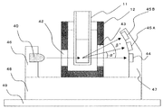
- FIG. 2 is a schematic diagram of an optical system in one embodiment of the present invention.
- the irradiation light from the light source 40 passes through the light projection window 42 formed in the thermostatic chamber 12 and is irradiated to the measurement target substance in the reaction vessel 11.
- the transmitted light from the substance to be measured passes through the light receiving window 43 formed in the thermostat 12 and is received by the transmitted light detector 44 of the photometer 41.
- Scattered light from the substance to be measured passes through the light receiving window 43 and has an angle of ⁇ ° with respect to the optical axis and a scattered light detector 45a of the photometer 41 and a scattered light detector having an angle of ⁇ °. Light is received at 45b.
- the light source holder 46 and the detector holder 47 are fixed to the photometer base 48, and the photometer base 48 is fixed to the mechanism base 49.
- FIG. 3 is a diagram for explaining a sudden change (1) at a single measurement point.
- foreign substances and bubbles in the thermostatic chamber fluid outside the reaction vessel cross the optical axis for photometry, so that a temporary decrease in transmitted light amount (increase in absorbance) and an increase in scattered light amount are observed. appear.
- FIG. 4 is a diagram for explaining sudden fluctuation (2) at a plurality of measurement points.
- foreign substances and bubbles floating in the reaction solution in the reaction vessel cross the optical axis over time, so that the amount of transmitted light decreases (increased absorbance) and the amount of scattered light increases at multiple measurement points. To occur.
- an automatic analyzer and a measurement value abnormality that can detect a measurement value abnormality derived from a reaction process abnormality due to bubbles or foreign matters without complicating the processing and function of the device A detection method can be realized.
Landscapes
- Physics & Mathematics (AREA)
- Health & Medical Sciences (AREA)
- Life Sciences & Earth Sciences (AREA)
- Chemical & Material Sciences (AREA)
- Analytical Chemistry (AREA)
- Biochemistry (AREA)
- General Health & Medical Sciences (AREA)
- General Physics & Mathematics (AREA)
- Immunology (AREA)
- Pathology (AREA)
- Engineering & Computer Science (AREA)
- Quality & Reliability (AREA)
- Automatic Analysis And Handling Materials Therefor (AREA)
Abstract
装置の処理や機能を複雑化することなく、気泡や異物による反応過程異常由来の測定値異常を検出可能な自動分析装置が実現される。測定値異常チェックが開始し、対の複数検知器からの光量データによる濃度演算結果が定量範囲内かをチェックする(ステップa、b)。濃度演算結果が定量範囲内なら、対象検出器での濃度演算結果の平均値を算出し、濃度演算結果が定量範囲外であった場合はフラグを付与し対象検出器での濃度演算結果の平均値を算出する(ステップc、d)。濃度演算結果の平均値における変動幅既定値を呼び出し対象の複数検出器における濃度演算結果の変動幅を算出し、既定範囲内に収まっているかを判断する(ステップe、f、g)。変動幅が既定範囲内なら濃度演算結果をディスプレイに出力し既定範囲外であれば再検査の依頼を表示させ測定値異状アラームを付加する(ステップh、i、j)。
Description
本発明は、血液や尿などの試料に含まれる成分量を分析する自動分析装置に関する。
試料に含まれる成分量を分析する分析装置として、光源からの光を、試料または試料と試薬とが混合した反応液に照射し、その結果得られる単一または複数の波長の透過光量を測定し吸光度を算出して、成分量を割り出す自動分析装置が広く用いられている。成分量はLambert-Beerの法則に従い算出される。
上記自動分析装置においては、回転と停止を繰り返す反応ディスクに、反応液を保持する多数の反応容器が円周状に並べられ、反応ディスクの回転中に、予め配置された透過光測定部により、約10分間、一定の時間間隔で吸光度の経時変化が測定される。測定終了後、反応容器は洗浄機構により洗浄されて、再び分析に使用される。
反応液の反応には、基質と酵素との呈色反応と、抗原と抗体との凝集反応の大きく2種類の反応が用いられる。前者は生化学分析であり、検査項目としてLDH(乳酸脱水素酵素)、ALP(アルカリホスファターゼ)、AST(アスパラギン酸アミノトランスフェナーゼ)などがある。また、後者は免疫分析であり、検査項目としてCRP(C反応性蛋白)、IgG(免疫グロブリン)、RF(リウマトイド因子)などがある。
後者の免疫分析で測定される測定物質は血中濃度が低いため高感度な検出系が要求される。例えば、ラテックス粒子の表面に抗体を感作(結合)させた試薬を用い、試料中に含まれる抗原との抗原抗体反応によりラテックス粒子を凝集させる際に、反応液に光を照射する。そして、ラテックス凝集塊に散乱されずに透過した光量を測定することでサンプル中に含まれる成分量を定量するラテックス凝集法での高感度化が図られてきた。
さらに、自動分析装置としては、試料からの透過光量を測定するのではなく、散乱光量を測定することによる高感度化も試みられている。
ところで、上記自動分析装置において、反応容器内または反応容器外の恒温槽流体内における異物や気泡により光源からの光の一部が遮断または散乱されて、対象物質を定量するための反応過程に異常をきたす場合があった。
異物や気泡による反応過程異常には、(1)単一測定ポイントでの突発的変動、(2)複数測定ポイントでの突発的変動、(3)反応過程全体での漸変動があげられる。上記反応過程異常(1)は、反応容器外の恒温槽流体内における異物や気泡が、測光のための光軸を横切るために、一時的な透過光量低下(吸光度の上昇)や散乱光量の上昇が見られるために発生する。
また、反応過程異常(2)は、反応容器内の反応液中に浮遊する異物や気泡が、時間をかけて測定のための光軸を横切ることにより、複数の測定ポイントにおいて透過光量低下や散乱光量の上昇が見られるために発生する。
また、反応過程異常(3)は、反応容器内の壁面に付着した微小な気泡が反応時間内で徐々に大きく成長し、または徐々に移動し、測定光束の一部が遮断または散乱されることにより、あたかも反応しているような光量の漸減(吸光度の漸増)や散乱光量の漸増を示す。
これらの反応過程異常は、測定結果の正確性、または精度に影響を与えることが知られており、高感度化の大きな障害となっている。
上記反応過程異常(1)及び(2)については、特許文献1に記載されているような反応過程内での変化率を比較する技術や、特許文献2に記載されているような正常反応に対するマハラノビス距離を算出し異常反応を判別する技術により、チェックすることができる。
また、上記反応過程異常(3)については、あたかも正常に反応しているような反応過程になるため、対象物質の濃度が未知である通常の検査業務において、チェックすることは容易ではない。
このため、特許文献3には、反応液の吸光度を測定する測定部以外に反応容器を直接撮像する画像取得部を備え、反応過程と画像情報とにより、気泡等が原因となる反応過程の異常をチェックする技術が示されている。
しかしながら、特許文献3に記載された技術では、反応容器内壁のどの部分に気泡が付着するかは判断できないため、内壁の複数個所の撮影が必要であり、撮影装置の機構が複雑化してしまう。
また、高感度な散乱光測定をしている場合は、直径数μmの気泡による影響も考えられるため、そのような微小な気泡をチェックするには高解像度な撮影が必要であり、処理速度や記録容量等が問題となる。
さらに、反応過程と撮影した画像とを同時にチェックしても、実際に測定結果にどの程度の影響があったか判断することは困難である。このため、測定結果への影響が無視できるほど小さかったとしても、再検査が必要と判断してしまう恐れもあり、試薬を浪費してしまう可能性がある。特に、反応過程異常(3)のような反応過程全体での漸変動については、測定結果への影響の判断は困難である。
本発明の目的は、装置の処理や機能を複雑化することなく、気泡や異物による反応過程異常由来の測定値異常を検出可能な自動分析装置および測定値異常検出方法を実現することである。
上記目的を達成するため、本発明は次のように構成される。
試料を反応容器に分注する試料分注機構と、上記反応容器内の試料を分析する複数の光度検知器と、上記試料の分析結果を表示する表示部とを有し試料を分析する自動分析装置及び測定値異常検出方法において、上記複数の光度検知器の各光度検知器について、各光度検知器の同一試料に対する複数の検出値から上記試料の濃度を演算し、演算した濃度の変動幅を算出し、算出した変動幅が予め定めた許容変動幅以内か否かを判断し、上記複数の光度検知器のうちのいずれかの光度計の検出値から算出した濃度の変動幅が許容変動幅以内でなければ、反応過程異常であることを上記表示部に表示させる。
装置の処理や機能を複雑化することなく、気泡や異物による反応過程異常由来の測定値異常を検出可能な自動分析装置および測定値異常検出方法を実現することができる。
以下、本発明の実施形態を図面に基づいて詳細に説明する。
なお、本発明の実施形態を説明するための全図において同一機能を有するものは原則として同一の符号を付すようにし、その繰り返しの説明は可能な限り省略する。
図1は、本発明の一実施例が適用される自動分析装置の全体構成図である。図1において、自動分析装置1は、主に、反応ディスク(反応容器保持機構)10と、サンプルディスク20と、試薬ディスク(試薬容器保持機構)30a及び30bと、光源40と、光度計41と、コンピュータ50とを備える。
反応ディスク10は、間欠回転可能であり、この反応ディスク10上に透光性材料からなる多数の反応容器11が周方向に沿って配置されている。反応容器11は、恒温槽12により所定温度(例えば37°C)に維持されている。恒温槽12内の流体は、恒温維持装置13により温度調整されている。
サンプルディスク20上には、血液、尿等の生体サンプルを収容する多数の検体容器21が、図示の例では二重に周方向に沿って載置されている。また、サンプルディスク20の近傍には、サンプル分注機構(試料分注機構)22が配置されている。このサンプル分注機構22は、可動アーム23と、これに取り付けられたピペットノズル24とを備えている。
上記構成により、サンプル分注機構22は、サンプル分注時にはピペットノズル24が可動アーム23により分注位置に移動して、サンプルディスク20の吸入位置に位置する検体容器21から所定量のサンプルを吸入し、そのサンプルを反応ディスク10上の吐出位置にある反応容器11内に吐出する。
試薬ディスク30a、30bは、互いに概ね同径かつ同形状のディスクであり、試薬保冷庫31a、31bがそれぞれ周方向に沿って配置されている。この試薬保冷庫31a、31bには、バーコードのように試薬識別情報を表示したラベルが貼られた複数の試薬ボトル32a、32bが、試薬ディスク30a、30bの周方向に沿ってそれぞれ載置されている。
これらの試薬ボトル32a、32bには、自動分析装置1により分析され得る分析項目に対応する試薬液が収容されている。また、各試薬保冷庫31a、31bは、バーコード読み取り装置33a、33bが付属されており、これらの装置33a、33bが試薬登録時に各試薬ボトル32a、32bの外壁に表示されているバーコードを読み取る。読み取られた試薬情報は、試薬ディスク30a、30b上のポジションとともにメモリ56に登録される。
また、試薬ディスク30a、30bの近傍には、サンプル分注機構22と概ね同様の機構をなす試薬分注機構34a、34bがそれぞれ配置されている。試薬分注時には、これらが備えるピペットノズルにより、反応ディスク10上の試薬受け入れ位置に位置付けられる検査項目に応じた試薬ボトル32a、32bから試薬液を吸入し、該当する反応容器11内へ吐出する。
反応ディスク10、試薬ディスク30a、30bおよび試薬分注機構34a、34bに囲まれる位置には、攪拌機構35a、35bが配置されている。反応容器11内に収容されたサンプルと試薬との混合液は、この攪拌機構35a、35bにより攪拌されて反応が促進される。
ここで、光源40は反応ディスク10の中心部付近に配置され、光度計41は反応ディスク10の外周側に配置されており、攪拌を終えた反応容器11の列は光源40と光度計41とによって挟まれた測光位置を通るように回転移動する。なお、光源40と散乱光度計41は光検出系を構成する。
各反応容器11内におけるサンプルと試薬との反応液は、反応ディスク10の回転動作中に光度計41の前を横切る度に測光される。サンプル毎に測定された散乱光のアナログ信号は、A/D(アナログ/デジタル)変換器54に入力される。
使用済みの反応容器11は、反応ディスク10の近傍に配置された反応容器洗浄機構36により、内部が洗浄されて繰り返しの使用を可能にする。
次に、図1の自動分析装置1における制御系及び信号処理系について簡単に説明する。コンピュータ50は、インターフェース51を介して、サンプル分注制御部52、試薬分注制御部53、A/D変換器54に接続されている。コンピュータ50は、サンプル分注制御部52に対して指令を送り、サンプルの分注動作を制御する。また、コンピュータ50は、試薬分注制御部53に対して指令を送り、試薬の分注動作を制御する。
A/D変換器54によってデジタル信号に変換された光度計41の測光値は、コンピュータ50に取り込まれる。
インターフェース51には、印字するためのプリンタ55、記憶装置であるメモリ56や外部出力メディア57、操作指令等を入力するためのキーボード58、画面表示するためのCRTディスプレイ(表示装置)59が接続されている。表示装置59としては、CRTディスプレイの他に液晶ディスプレイなどを採用できる。
メモリ56は、例えばハードディスクメモリまたは外部メモリにより構成される。メモリ56には、各操作者のパスワード、各画面の表示レベル、分析パラメータ、分析項目依頼内容、キャリブレーション結果、分析結果等の情報が記憶される。
次に、図1の自動分析装置1におけるサンプルの分析動作を説明する。自動分析装置1によって分析可能な項目に関する分析パラメータは、予めキーボード58等の情報入力装置を介して入力されておリ、メモリ56に記憶されている。操作者は、ディスプレイ59の操作機能画面を用いて各サンプルに依頼されている検査項目を選択する。
この際に、患者IDなどの情報もキーボード58から入力される。各サンプルに対して指示された検査項目を分析するために、サンプル分注機構22のピペットノズル24は、分析パラメータに従って、検体容器21から反応容器11へ所定量のサンプルを分注する。
サンプル(試料)が分注された反応容器11は、反応ディスク10の回転によって移送され、試薬受け入れ位置に停止する。試薬分注機構34a、34bのピペットノズルは、該当する検査項目の分析パラメータに従って、反応容器11に所定量の試薬液を分注する。サンプルと試薬の分注順序は、この例とは逆に、サンプルより試薬が先であってもよい。
その後、攪拌機構35a、35bにより、サンプルと試薬との攪拌が行われ、混合される。この反応容器11が、測光位置を横切る時、光度計41により反応液の透過光または散乱光が測光される。測光された透過光または散乱光は、A/D変換器54により光量に比例した数値に変換され、インターフェース51を経由して、コンピュータ50に取り込まれる。
この変換された数値を用い、検査項目毎に指定された分析法により予め測定しておいた検量線に基づき、濃度データが算出される。各検査項目の分析結果としての成分濃度データは、プリンタ55やCRTディスプレイ59の画面に出力される。
以上の測定動作が実行される前に、操作者は、分析測定に必要な種々のパラメータの設定や試料の登録を、CRTディスプレイ59の操作画面を介して行う。また、操作者は、測定後の分析結果をCRTディスプレイ59上の操作画面により確認する。
図2は、本発明の一実施例における光学系の概略図である。図2において、光源40からの照射光は、恒温槽12に形成された投光窓42を通過して、反応容器11内の測定対象物質に照射される。測定対象物質からの透過光は、恒温槽12に形成された受光窓43を通過して光度計41の透過光用検知器44にて受光される。測定対象物質からの散乱光は、受光窓43を通過して、光軸に対しα°の角度を持つ、光度計41の散乱光用検知器45aおよびβ°の角度を持つ散乱光用検知器45bにて受光される。
複数の散乱光検出器は、光軸に対し同角度で上下対称に配置しても良い。光源40は、光源ホルダ(光源が配置されるベース部材)46により固定され、光度計41の検知器44、45a、45bは検知器ホルダ(各検知器が配置されるベース部材)47に配置されて固定される。
また、光源ホルダ46と検知器ホルダ47は、光度計ベース48に固定され、光度計ベース48は機構ベース49に固定される。
図3、図4、図5は、気泡や異物による反応過程異常を説明する図である。
図3は単一測定ポイントでの突発的変動(1)を説明する図である。図3において、反応容器外の恒温槽流体内における異物や気泡が、測光のための光軸を横切るために、一時的な透過光量低下(吸光度の上昇)や散乱光量の上昇が見られるために発生する。
図4は複数測定ポイントでの突発的変動(2)を説明する図である。図4において、反応容器内の反応液内に浮遊する異物や気泡が、時間をかけて光軸を横切ることにより、複数の測定ポイントにおいて透過光量低下(吸光度の上昇)や散乱光量の上昇が見られるために発生する。
図5は反応過程全体の漸変動を説明する図である。図5において、反応過程全体での漸変動は、反応容器内の壁面に付着した微小な気泡が反応時間内で徐々に大きく成長、または徐々に移動し、光束の一部が遮断または散乱されることにより、あたかも反応しているような光量の漸減(吸光度の漸増)や散乱光量の漸増を示す。
自動分析装置の分析法として一般的に用いられているエンドポイント法やレート法などにおいて、濃度演算に使用する測定ポイントでこれらの反応過程異常が発生すると、濃度演算結果が異常値となってしまい誤報告につながる可能性がある。
図6は、本発明の一実施例における、各々の検出器44、45A、45Bの対象物質に対する検量線の一例を示すグラフである。図6に示したグラフは、段階的に濃度調整された標準液を複数回測定し、その光量平均値を各々の濃度における光量データとして検量線を作成している。検量線作成は、既知の濃度の試料を複数回測定するので、反応過程異状による測定値異状が発生しても発見が容易なため、本発明による手段を用いなくても問題となることはない。それぞれの検出器の検量線は、各々の受光角度応じた固有の検量線となる。
図6において、縦軸は光量を示し、横軸は対象物質濃度を示す。黒丸は検出器44で検出された透過光、三角形は検出器45Aで検出されたα°散乱光、四角形は検出器45Bで検出されたβ°散乱光である。
これらの検量線を用いて、未知の濃度の定量測定を実施するが、実際の測定では、試薬の組成による感度や再現性の観点から、最適な受光角度が予め設定されており、その受光角度の検出器からの光量データにより、定量測定を実施する。
しかしながら、その他の受光角度においても定量測定に関しては最適ではないものの、あるばらつき範囲において定量測定が可能であり、本発明の実施例における測定値異状チェックに用いることができる。
また、それぞれの検量線は、例えばCV<20%以下のばらつき範囲により規定される低濃度側の定量限界、およびプロゾーン現象などで制限を受ける高濃度側の定量限界内において定量可能範囲を決定して使用する。
したがって、各検出器44、45A、45Bの定量可能範囲が交わる範囲において、本発明の測定値異常チェックが可能となる。
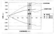
図7は、本発明の一実施例における、正常な測定結果のばらつきの例を示すグラフである。破線で示す範囲が変動幅許容範囲であり、各々の検量線における定量可能範囲内の測定であれば、それぞれの測定結果は、変動幅許容範囲内に収まる。図7に示した例では、0°透過光、α°散乱光、β°散乱光を用いてチェックしているが、透過光測定と散乱光測定では感度や定量可能範囲が大きく異なる場合があるため、散乱光測定の結果のみをチェックに使用しても良い。また、反応容器への光の照射位置が異なる複数の吸光光度計により、同様のチェックが可能である。
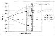
図8は、本発明の一実施例における、異常な測定結果のばらつきの例を示すグラフである。上述した単一測定ポイントの突発的変動(1)、複数測定ポイントの突発的変動(2)、反応過程全体の漸変動(3)が生じ、異常反応過程となった場合、すべての受光角度に影響が出るとき、いずれかのみに影響が出るときがあるが、いずれのときにおいても気泡や異物に対する各々の受光角度での感度や、光学系の違いにより、測定結果は正常状態に比べて変動幅が大きくなる。
したがって、測定結果の変動幅が予め設定した変動幅既定値より大きくなった場合に異常反応と識別することができる。このとき、気泡や異物により各々の受光角度の測定結果が同様に変動してしまうと、異常が発生しているのもかかわらず、変動幅は小さい。このため、異常反応を検出できないと予想される。
しかし、気泡や異物により各々の受光角度の測定結果が同様に変動する可能性は非常に低く、変動幅既定値を適切に設定すれば確実に異常反応を判別できる。
図9は、本発明の一実施例の自動分析装置による測定値異常チェックの動作フローチャートであり、図10は、コンピュータ50の測定値異常チェックを行うための機能ブロック図である。図10において、コンピュータ50は、検知器44、45A、45Bからの検知信号に基づき、濃度を演算する濃度演算部501と、定量範囲判断部502と、平均値演算部503と、許容変動幅テーブル504と、変動幅演算判断部505とを備えている。
図9に示した動作は、図1で示した自動分析装置による分析動作により測定結果が得られた後に、自動的に実行される。
図9及び図10において、まず、測定値異常チェックが開始されると(ステップ(a))、濃度演算部501により実行された、対象となる複数の検知器からの光量データによる濃度演算結果が、それぞれ定量範囲内か否かを定量範囲判断部502によりチェックされる(ステップ(b))。
ステップ(b)において、濃度演算結果が定量範囲内であれば、平均値演算部503は、そのまま、対象の検出器での濃度演算結果の平均値を算出する(ステップ(d))。
ステップ(b)において、濃度演算結果が定量範囲外であった場合、定量範囲判断部502は定量範囲外のフラグを付与(ステップ(c))する。その後、平均均値演算部503は、対象の検出器での濃度演算結果の平均値を算出する(ステップ(d))。これは、測定値が定量範囲外であっても、臨床的な判断材料になる場合があるので、フラグを付与した上で測定値異常チェックを継続する。
変動幅演算判断部505は、平均値演算部503が算出した濃度演算結果の平均値における変動幅既定値を許容変動幅テーブル504から呼び出しステップ(e))、次に対象の複数検出器における濃度演算結果の変動幅を算出する(ステップ(f))。変動幅演算判断部505は、算出した変動幅が既定の範囲内に収まっているかを判断する(ステップ(g))。
ステップ(g)において、変動幅が既定範囲内であれば、変動幅演算判断部505は、濃度演算結果をディスプレイ59に出力し(ステップ(h))、測定値異常チェック終了となる(ステップ(k))。
ステップ(g)において、変動幅が、既定範囲外であれば、変動幅演算判断部505は、再検査の依頼をディスプレイ59に表示させ(ステップ(i))、測定値異状アラームを付加する(ステップ(j))。そして、測定値異常チェックが終了する(ステップ(k))。
図11は、本発明の一実施例における、測定値異常チェックの変動幅既定範囲を入力するための画面の例である。
変動幅既定範囲は、キーボード58が操作されて、変動幅許容テーブル504に格納される。また、図11に示した入力画面はディスプレイ59に表示される。
図11において、項目名毎に、許容変動幅が設定される。また、濃度範囲毎に許容変動幅を設定することができる。つまり、測定濃度の平均値が0.01~0.1mg/dLの範囲内であれば許容変動幅は0.01mg/dLとなり、測定濃度の平均値が0.1~1.0mg/dLの範囲内であれば許容変動幅は0.1mg/dLとなる。
なお、既定範囲については、いずれの濃度領域においても一定値で設定しても良いし、高濃度領域では変動幅が大きくなることが一般に知られているので、濃度に応じて変動幅既定範囲を設定しても良い。また、このときいずれの濃度域の変動幅既定範囲を用いるかを、測定値の平均値から決定しても良いし、測定結果の最小値や最大値で決定する方法も考えられる。測定値の最小値を用いた場合は、平均値を用いるよりもチェックの感度は高くなり、測定値の最大値を用いた場合は、平均値を用いるよりもチェックの感度は低くなる。さらに、変動幅既定範囲を分析項目の固有値として設定することも考えられるが、検知器それぞれの検量線作成時に、各々の濃度における複数データの変動幅から決定してもよい。これらの既定値は、手入力のほか、装置側で自動入力とすることも可能である。また、測定項目ごとのバーコードなどに既定値情報を組み込んでおくことで、装置がバーコードを読み取る構成も考えられる。
既定範囲は、測定する項目別に設定するほうが、チェックの精度は向上するが、測定項目よらず一律に決定することも可能である。
図12は、本発明の一実施例における、測定値異常アラーム表示画面の例であり、ディスプレイ59に表示される。測定値異常アラーム表示画面には、異常のレベル、異常内容を示すアラーム、発生時刻、詳細(説明と対処法)が表示されている。
測定値異常チェックにて異常と判断された場合に、反応過程を見比べることで異常となった原因を推定することも可能である。また、装置側で自動判定する構成も考えられる。
以上のように、本発明の一実施例によれば、装置の処理や機能を複雑化することなく、気泡や異物による反応過程異常由来の測定値異常を検出可能な自動分析装置および測定値異常検出方法を実現することができる。
なお、上述した例は、測定値異常の発生を自動的に判断して、その旨を表示する例であるが、例えば、図7、図8に示すように、変動幅許容範囲と、実際の測定値の変動幅を画面表示し、オペレータ等が目視で、測定値異常の発生を判断する構成とすることもできる。
1・・・自動分析装置、10・・・反応ディスク、11・・・反応容器、12・・・恒温槽、13・・・恒温維持装置、20・・・サンプルディスク、21・・・検体容器、22・・・サンプル分注機構、23・・・可動アーム、24・・・ピペットノズル、30a・・・試薬ディスク、30b・・・試薬ディスク、31a・・・試薬保冷庫、31b・・・試薬保冷庫、32a・・・試薬ボトル、32b・・・試薬ボトル、33a・・・バーコード読み取り装置、33b・・・バーコード読み取り装置、34a・・・試薬分注機構、34b・・・試薬分注機構、35a・・・攪拌機構、35b・・・攪拌機構、36・・・反応容器洗浄機構、40・・・光源、41・・・散乱光度計、42・・・投光窓、43・・・受光窓、44・・・透過光用検知器、45a・・・α°散乱光用検知器、45b・・・β°散乱光用検知器、46・・・光源ホルダ(光源が配置されるベース部材)、47・・・検知器ホルダ(各検知器が配置されるベース部材)、48・・・光度計ベース、49・・・機構ベース、50・・・コンピュータ、51・・・インターフェース、52・・・サンプル分注制御部、53・・・試薬分注制御部、54・・・A/D変換器、55・・・プリンタ、56・・・メモリ、57・・・外部出力メディア、58・・・キーボード、59・・・CRTディスプレイ(表示装置)、501・・・濃度演算部、502・・・定量範囲判断部、503・・・平均値演算部、504・・・許容変動幅テーブル、505・・・変動幅演算判断部
Claims (12)
- 試料を分析する自動分析装置において、
試薬容器を保持する試薬容器保持機構と、
反応容器を保持する反応容器保持機構と、
上記試薬容器に収容された試薬を上記反応容器に分注する試薬分注機構と、
試料を上記反応容器に分注する試料分注機構と、
上記反応容器内の試料を分析する複数の光度検知器と、
上記試料の分析結果を表示する表示部と、
上記試薬容器保持機構、上記反応容器保持機構、上記試薬分注機構、上記試料分注機構、上記複数の光度検知器、及び上記表示部を制御するとともに、上記複数の光度検知器の各光度検知器について、各光度検知器の同一試料に対する複数の検出値から上記試料の濃度を演算し、演算した濃度の変動幅を算出し、算出した変動幅が予め定めた許容変動幅以内か否かを判断し、上記複数の光度検知器のうちのいずれかの光度計の検出値から算出した濃度の変動幅が許容変動幅以内でなければ、反応過程異常であることを上記表示部に表示させる制御部と、
を備えることを特徴とする自動分析装置。 - 請求項1に記載の自動分析装置において、
上記複数の光度検知器のそれぞれに対して、対象物質の定量のための検量線を記憶するメモリを備え、上記制御部は、上記メモリに記憶された検量線に基づいて、試料の濃度を演算することを特徴とする自動分析装置。 - 請求項2に記載の自動分析装置において、
上記複数の光度検知器は、測定対象物質からの透過光を検知する光度検知器と、測定対象物質からの散乱光を検知する光度検知器とを有することを特徴とする自動分析装置。 - 請求項3に記載の自動分析装置において、
上記許容変動幅は、上記試料の濃度範囲別に設定され、上記制御部は、上記各光度検出器の出力値から算出した試料濃度の平均値を算出し、算出した上記平均値に従って、上記設定された許容変動幅を決定することを特徴とする自動分析装置。 - 請求項3に記載の自動分析装置において、
上記許容変動幅は、上記試料の濃度範囲別に設定され、上記制御部は、上記各光度検出器の出力値から算出した試料濃度の最小値に従って、上記設定された許容変動幅を決定することを特徴とする自動分析装置。 - 請求項3に記載の自動分析装置において、
上記許容変動幅は、上記試料の濃度範囲別に設定され、上記制御部は、上記各光度検出器の出力値から算出した試料濃度の最大値に従って、上記設定された許容変動幅を決定することを特徴とする自動分析装置。 - 試料を反応容器に分注する試料分注機構と、上記反応容器内の試料を分析する複数の光度検知器と、上記試料の分析結果を表示する表示部とを有し試料を分析する自動分析装置の測定値異常検出方法において、
上記複数の光度検知器の各光度検知器について、各光度検知器の同一試料に対する複数の検出値から上記試料の濃度を演算し、演算した濃度の変動幅を算出し、算出した変動幅が予め定めた許容変動幅以内か否かを判断し、上記複数の光度検知器のうちのいずれかの光度計の検出値から算出した濃度の変動幅が許容変動幅以内でなければ、反応過程異常であることを上記表示部に表示させることを特徴とする測定値異常検出方法。 - 請求項7に記載の測定値異常検出方法において、
上記複数の光度検知器のそれぞれに対して、対象物質の定量のための検量線をメモリに記憶し、記憶した検量線に基づいて、試料の濃度を演算することを特徴とする測定値異常検出方法。 - 請求項8に記載の測定値異常検出方法において、
上記複数の光度検知器は、測定対象物質からの透過光を検知する光度検知器と、測定対象物質からの散乱光を検知する光度検知器とを有することを特徴とする測定値異常検出方法。 - 請求項9に記載の測定値異常検出方法において、
上記許容変動幅は、上記試料の濃度範囲別に設定され、上記各光度検出器の出力値から算出した試料濃度の平均値を算出し、算出した上記平均値に従って、上記設定された許容変動幅を決定することを特徴とする測定値異常検出方法。 - 請求項9に記載の測定値異常検出方法において、
上記許容変動幅は、上記試料の濃度範囲別に設定され、上記各光度検出器の出力値から算出した試料濃度の最小値に従って、上記設定された許容変動幅を決定することを特徴とする測定値異常検出方法。 - 請求項9に記載の測定値異常検出方法において、
上記許容変動幅は、上記試料の濃度範囲別に設定され、上記各光度検出器の出力値から算出した試料濃度の最大値に従って、上記設定された許容変動幅を決定することを特徴とする測定値異常検出方法。
Priority Applications (3)
| Application Number | Priority Date | Filing Date | Title |
|---|---|---|---|
| CN201280064619.8A CN104011547B (zh) | 2011-12-26 | 2012-11-22 | 自动分析装置及测定值异常检测方法 |
| EP12861407.0A EP2799882B1 (en) | 2011-12-26 | 2012-11-22 | Automatic analysis device and detection method for measurement value abnormalities |
| US14/367,066 US9506942B2 (en) | 2011-12-26 | 2012-11-22 | Automatic analyzer and method for detecting measurement value abnormalities |
Applications Claiming Priority (2)
| Application Number | Priority Date | Filing Date | Title |
|---|---|---|---|
| JP2011284467A JP5897323B2 (ja) | 2011-12-26 | 2011-12-26 | 自動分析装置および測定値異常検出方法 |
| JP2011-284467 | 2011-12-26 |
Publications (1)
| Publication Number | Publication Date |
|---|---|
| WO2013099486A1 true WO2013099486A1 (ja) | 2013-07-04 |
Family
ID=48696985
Family Applications (1)
| Application Number | Title | Priority Date | Filing Date |
|---|---|---|---|
| PCT/JP2012/080377 Ceased WO2013099486A1 (ja) | 2011-12-26 | 2012-11-22 | 自動分析装置および測定値異常検出方法 |
Country Status (5)
| Country | Link |
|---|---|
| US (1) | US9506942B2 (ja) |
| EP (1) | EP2799882B1 (ja) |
| JP (1) | JP5897323B2 (ja) |
| CN (1) | CN104011547B (ja) |
| WO (1) | WO2013099486A1 (ja) |
Families Citing this family (16)
| Publication number | Priority date | Publication date | Assignee | Title |
|---|---|---|---|---|
| JP6472965B2 (ja) * | 2014-09-11 | 2019-02-20 | 日本電子株式会社 | 自動分析装置及び異常判定方法 |
| WO2016130964A1 (en) | 2015-02-13 | 2016-08-18 | Abbott Laboratories | Decapping and capping apparatus, systems and methods for use in diagnostic analyzers |
| JP6567873B2 (ja) * | 2015-05-22 | 2019-08-28 | 株式会社日立ハイテクノロジーズ | 自動分析装置 |
| JP6658091B2 (ja) * | 2016-02-29 | 2020-03-04 | 株式会社島津製作所 | 分析測定装置システム |
| US10976333B2 (en) * | 2016-07-19 | 2021-04-13 | Hitachi High-Tech Corporation | Automatic analysis device and automatic analysis method |
| ES2823182T3 (es) | 2016-07-19 | 2021-05-06 | Autronica Fire & Security As | Sistema y método de verificación de la integridad operativa de un detector de humo |
| CN110023950B (zh) | 2016-10-28 | 2023-08-08 | 拜克门寇尔特公司 | 物质准备评估系统 |
| EP3734288B1 (en) * | 2017-12-26 | 2023-11-08 | Hitachi High-Tech Corporation | Automated analyzer and automated analysis method |
| CN112362885B (zh) * | 2018-02-11 | 2023-06-16 | 科美博阳诊断技术(上海)有限公司 | 一种全自动光激化学发光检测仪 |
| WO2020250507A1 (ja) * | 2019-06-11 | 2020-12-17 | 株式会社日立ハイテク | 自動分析装置、および異常検知方法 |
| CN114174800B (zh) * | 2019-08-05 | 2024-10-15 | 株式会社日立高新技术 | 自动分析装置 |
| CN114137234B (zh) * | 2020-09-03 | 2025-09-19 | 深圳迈瑞生物医疗电子股份有限公司 | 血液细胞分析仪的质量控制方法和血液细胞分析仪 |
| JP7420960B2 (ja) * | 2020-09-30 | 2024-01-23 | 株式会社日立ハイテク | データ処理装置および自動分析装置 |
| CN112710627B (zh) * | 2020-12-09 | 2022-05-27 | 深圳市科曼医疗设备有限公司 | 一种特定蛋白浓度的检测方法及检测装置 |
| JP7187528B2 (ja) * | 2020-12-28 | 2022-12-12 | 本田技研工業株式会社 | 車両用認識装置、車両制御システム、車両用認識方法、およびプログラム |
| JP2023092286A (ja) * | 2021-12-21 | 2023-07-03 | アズビル株式会社 | 濃度測定装置、濃度測定システム及び濃度測定方法 |
Citations (11)
| Publication number | Priority date | Publication date | Assignee | Title |
|---|---|---|---|---|
| JPH067054U (ja) * | 1992-06-30 | 1994-01-28 | 株式会社ニッテク | 自動分析装置における気泡検出装置 |
| JP2000275254A (ja) | 1999-03-24 | 2000-10-06 | Olympus Optical Co Ltd | 自動分析装置 |
| JP2004347385A (ja) * | 2003-05-21 | 2004-12-09 | Hitachi Ltd | 異常検出システム及び異常検出方法 |
| JP2006337125A (ja) * | 2005-06-01 | 2006-12-14 | Hitachi High-Technologies Corp | 自動分析装置,自動分析装置を用いた分析方法 |
| JP2007248089A (ja) | 2006-03-14 | 2007-09-27 | Hitachi High-Technologies Corp | 自己診断型自動分析装置 |
| JP2011013142A (ja) | 2009-07-03 | 2011-01-20 | Toshiba Corp | 自動分析装置 |
| WO2011093402A1 (ja) * | 2010-01-29 | 2011-08-04 | 株式会社日立ハイテクノロジーズ | 分析装置 |
| JP2011153944A (ja) * | 2010-01-28 | 2011-08-11 | Hitachi High-Technologies Corp | 自動分析装置 |
| WO2011162113A1 (ja) * | 2010-06-22 | 2011-12-29 | 株式会社日立ハイテクノロジーズ | 自動分析装置 |
| WO2011162139A1 (ja) * | 2010-06-23 | 2011-12-29 | 株式会社日立ハイテクノロジーズ | 自動分析装置および自動分析方法 |
| JP2012141246A (ja) * | 2011-01-05 | 2012-07-26 | Toshiba Corp | 自動分析装置 |
Family Cites Families (14)
| Publication number | Priority date | Publication date | Assignee | Title |
|---|---|---|---|---|
| US4234538A (en) * | 1977-10-28 | 1980-11-18 | Coulter Electronics, Inc. | Apparatus for monitoring chemical reactions and employing moving photometer means |
| US4762413A (en) * | 1984-09-07 | 1988-08-09 | Olympus Optical Co., Ltd. | Method and apparatus for measuring immunological reaction with the aid of fluctuation in intensity of scattered light |
| JP2001249134A (ja) * | 1999-12-28 | 2001-09-14 | Matsushita Electric Ind Co Ltd | タンパク質濃度計測用試薬、これを用いたタンパク質濃度計測方法および尿検査方法 |
| JP2007322324A (ja) * | 2006-06-02 | 2007-12-13 | Olympus Corp | 分析装置 |
| JP5260903B2 (ja) * | 2007-07-06 | 2013-08-14 | 株式会社東芝 | 自動分析装置 |
| JP4654256B2 (ja) * | 2008-02-28 | 2011-03-16 | 株式会社日立ハイテクノロジーズ | 自動分析装置 |
| CN102089644B (zh) * | 2008-07-30 | 2014-09-10 | 株式会社日立高新技术 | 试样分析装置 |
| JP5268609B2 (ja) * | 2008-12-09 | 2013-08-21 | 株式会社東芝 | 暗号処理装置及び演算方法 |
| JP5564037B2 (ja) * | 2009-04-09 | 2014-07-30 | 株式会社日立ハイテクノロジーズ | 自動分析装置 |
| JP5379044B2 (ja) | 2010-02-25 | 2013-12-25 | 株式会社日立ハイテクノロジーズ | 自動分析装置 |
| JP5599219B2 (ja) * | 2010-04-20 | 2014-10-01 | 株式会社日立ハイテクノロジーズ | 自動分析装置及び自動分析方法 |
| JP5481402B2 (ja) * | 2011-01-17 | 2014-04-23 | 株式会社日立ハイテクノロジーズ | 自動分析装置 |
| JP6013796B2 (ja) * | 2012-06-25 | 2016-10-25 | 株式会社日立ハイテクノロジーズ | 自動分析装置及び試料測定方法 |
| JP5948173B2 (ja) | 2012-07-20 | 2016-07-06 | 株式会社日立ハイテクノロジーズ | 自動分析装置及び自動分析方法 |
-
2011
- 2011-12-26 JP JP2011284467A patent/JP5897323B2/ja active Active
-
2012
- 2012-11-22 US US14/367,066 patent/US9506942B2/en not_active Expired - Fee Related
- 2012-11-22 EP EP12861407.0A patent/EP2799882B1/en not_active Not-in-force
- 2012-11-22 CN CN201280064619.8A patent/CN104011547B/zh active Active
- 2012-11-22 WO PCT/JP2012/080377 patent/WO2013099486A1/ja not_active Ceased
Patent Citations (11)
| Publication number | Priority date | Publication date | Assignee | Title |
|---|---|---|---|---|
| JPH067054U (ja) * | 1992-06-30 | 1994-01-28 | 株式会社ニッテク | 自動分析装置における気泡検出装置 |
| JP2000275254A (ja) | 1999-03-24 | 2000-10-06 | Olympus Optical Co Ltd | 自動分析装置 |
| JP2004347385A (ja) * | 2003-05-21 | 2004-12-09 | Hitachi Ltd | 異常検出システム及び異常検出方法 |
| JP2006337125A (ja) * | 2005-06-01 | 2006-12-14 | Hitachi High-Technologies Corp | 自動分析装置,自動分析装置を用いた分析方法 |
| JP2007248089A (ja) | 2006-03-14 | 2007-09-27 | Hitachi High-Technologies Corp | 自己診断型自動分析装置 |
| JP2011013142A (ja) | 2009-07-03 | 2011-01-20 | Toshiba Corp | 自動分析装置 |
| JP2011153944A (ja) * | 2010-01-28 | 2011-08-11 | Hitachi High-Technologies Corp | 自動分析装置 |
| WO2011093402A1 (ja) * | 2010-01-29 | 2011-08-04 | 株式会社日立ハイテクノロジーズ | 分析装置 |
| WO2011162113A1 (ja) * | 2010-06-22 | 2011-12-29 | 株式会社日立ハイテクノロジーズ | 自動分析装置 |
| WO2011162139A1 (ja) * | 2010-06-23 | 2011-12-29 | 株式会社日立ハイテクノロジーズ | 自動分析装置および自動分析方法 |
| JP2012141246A (ja) * | 2011-01-05 | 2012-07-26 | Toshiba Corp | 自動分析装置 |
Non-Patent Citations (1)
| Title |
|---|
| See also references of EP2799882A4 |
Also Published As
| Publication number | Publication date |
|---|---|
| EP2799882A1 (en) | 2014-11-05 |
| EP2799882B1 (en) | 2019-07-17 |
| CN104011547A (zh) | 2014-08-27 |
| US20140356964A1 (en) | 2014-12-04 |
| EP2799882A4 (en) | 2015-08-19 |
| JP2013134139A (ja) | 2013-07-08 |
| US9506942B2 (en) | 2016-11-29 |
| CN104011547B (zh) | 2016-07-06 |
| JP5897323B2 (ja) | 2016-03-30 |
Similar Documents
| Publication | Publication Date | Title |
|---|---|---|
| JP5897323B2 (ja) | 自動分析装置および測定値異常検出方法 | |
| JP6013796B2 (ja) | 自動分析装置及び試料測定方法 | |
| US12146890B2 (en) | Automated analyzer and automated analysis method | |
| US11971425B2 (en) | Automatic analysis device and automatic analysis method | |
| JP5216051B2 (ja) | 自動分析装置および自動分析方法 | |
| JP5296015B2 (ja) | 自動分析装置 | |
| JP5481402B2 (ja) | 自動分析装置 | |
| CN104094100B (zh) | 自动分析装置 | |
| JP5661124B2 (ja) | 自動分析装置 | |
| JP5952180B2 (ja) | 自動分析装置、プログラムおよび記録媒体ならびに検体の自動分析方法 |
Legal Events
| Date | Code | Title | Description |
|---|---|---|---|
| 121 | Ep: the epo has been informed by wipo that ep was designated in this application |
Ref document number: 12861407 Country of ref document: EP Kind code of ref document: A1 |
|
| WWE | Wipo information: entry into national phase |
Ref document number: 14367066 Country of ref document: US Ref document number: 2012861407 Country of ref document: EP |
|
| NENP | Non-entry into the national phase |
Ref country code: DE |