WO2013100325A1 - 이동 단말기 - Google Patents
이동 단말기 Download PDFInfo
- Publication number
- WO2013100325A1 WO2013100325A1 PCT/KR2012/007708 KR2012007708W WO2013100325A1 WO 2013100325 A1 WO2013100325 A1 WO 2013100325A1 KR 2012007708 W KR2012007708 W KR 2012007708W WO 2013100325 A1 WO2013100325 A1 WO 2013100325A1
- Authority
- WO
- WIPO (PCT)
- Prior art keywords
- light
- film
- light source
- mobile terminal
- optical
- Prior art date
- Legal status (The legal status is an assumption and is not a legal conclusion. Google has not performed a legal analysis and makes no representation as to the accuracy of the status listed.)
- Ceased
Links
Images


Classifications
-
- G—PHYSICS
- G03—PHOTOGRAPHY; CINEMATOGRAPHY; ANALOGOUS TECHNIQUES USING WAVES OTHER THAN OPTICAL WAVES; ELECTROGRAPHY; HOLOGRAPHY
- G03H—HOLOGRAPHIC PROCESSES OR APPARATUS
- G03H1/00—Holographic processes or apparatus using light, infrared or ultraviolet waves for obtaining holograms or for obtaining an image from them; Details peculiar thereto
- G03H1/22—Processes or apparatus for obtaining an optical image from holograms
- G03H1/2202—Reconstruction geometries or arrangements
-
- H—ELECTRICITY
- H04—ELECTRIC COMMUNICATION TECHNIQUE
- H04N—PICTORIAL COMMUNICATION, e.g. TELEVISION
- H04N13/00—Stereoscopic video systems; Multi-view video systems; Details thereof
- H04N13/30—Image reproducers
- H04N13/302—Image reproducers for viewing without the aid of special glasses, i.e. using autostereoscopic displays
- H04N13/32—Image reproducers for viewing without the aid of special glasses, i.e. using autostereoscopic displays using arrays of controllable light sources; using moving apertures or moving light sources
-
- G—PHYSICS
- G03—PHOTOGRAPHY; CINEMATOGRAPHY; ANALOGOUS TECHNIQUES USING WAVES OTHER THAN OPTICAL WAVES; ELECTROGRAPHY; HOLOGRAPHY
- G03H—HOLOGRAPHIC PROCESSES OR APPARATUS
- G03H1/00—Holographic processes or apparatus using light, infrared or ultraviolet waves for obtaining holograms or for obtaining an image from them; Details peculiar thereto
- G03H1/04—Processes or apparatus for producing holograms
-
- G—PHYSICS
- G03—PHOTOGRAPHY; CINEMATOGRAPHY; ANALOGOUS TECHNIQUES USING WAVES OTHER THAN OPTICAL WAVES; ELECTROGRAPHY; HOLOGRAPHY
- G03H—HOLOGRAPHIC PROCESSES OR APPARATUS
- G03H1/00—Holographic processes or apparatus using light, infrared or ultraviolet waves for obtaining holograms or for obtaining an image from them; Details peculiar thereto
- G03H1/22—Processes or apparatus for obtaining an optical image from holograms
- G03H1/2294—Addressing the hologram to an active spatial light modulator
-
- G—PHYSICS
- G03—PHOTOGRAPHY; CINEMATOGRAPHY; ANALOGOUS TECHNIQUES USING WAVES OTHER THAN OPTICAL WAVES; ELECTROGRAPHY; HOLOGRAPHY
- G03H—HOLOGRAPHIC PROCESSES OR APPARATUS
- G03H1/00—Holographic processes or apparatus using light, infrared or ultraviolet waves for obtaining holograms or for obtaining an image from them; Details peculiar thereto
- G03H1/26—Processes or apparatus specially adapted to produce multiple sub- holograms or to obtain images from them, e.g. multicolour technique
-
- G—PHYSICS
- G06—COMPUTING OR CALCULATING; COUNTING
- G06T—IMAGE DATA PROCESSING OR GENERATION, IN GENERAL
- G06T17/00—Three-dimensional [3D] modelling for computer graphics
- G06T17/10—Constructive solid geometry [CSG] using solid primitives, e.g. cylinders, cubes
-
- G—PHYSICS
- G03—PHOTOGRAPHY; CINEMATOGRAPHY; ANALOGOUS TECHNIQUES USING WAVES OTHER THAN OPTICAL WAVES; ELECTROGRAPHY; HOLOGRAPHY
- G03H—HOLOGRAPHIC PROCESSES OR APPARATUS
- G03H1/00—Holographic processes or apparatus using light, infrared or ultraviolet waves for obtaining holograms or for obtaining an image from them; Details peculiar thereto
- G03H1/22—Processes or apparatus for obtaining an optical image from holograms
- G03H1/2202—Reconstruction geometries or arrangements
- G03H2001/2223—Particular relationship between light source, hologram and observer
-
- G—PHYSICS
- G03—PHOTOGRAPHY; CINEMATOGRAPHY; ANALOGOUS TECHNIQUES USING WAVES OTHER THAN OPTICAL WAVES; ELECTROGRAPHY; HOLOGRAPHY
- G03H—HOLOGRAPHIC PROCESSES OR APPARATUS
- G03H2227/00—Mechanical components or mechanical aspects not otherwise provided for
- G03H2227/02—Handheld portable device, e.g. holographic camera, mobile holographic display
-
- G—PHYSICS
- G03—PHOTOGRAPHY; CINEMATOGRAPHY; ANALOGOUS TECHNIQUES USING WAVES OTHER THAN OPTICAL WAVES; ELECTROGRAPHY; HOLOGRAPHY
- G03H—HOLOGRAPHIC PROCESSES OR APPARATUS
- G03H2270/00—Substrate bearing the hologram
- G03H2270/55—Substrate bearing the hologram being an optical element, e.g. spectacles
Definitions
- One embodiment of the present invention relates to a mobile terminal capable of outputting a holographic image.
- terminals are diversified, for example, terminals are implemented in the form of a multimedia player having complex functions such as taking a picture or video, playing a music or video file, playing a game, and receiving a broadcast. have.
- a portable terminal can move It may be divided into a mobile terminal (portable terminal) and a stationary terminal depending on whether or not.
- a portable terminal is a portable device that is portable and has one or more functions of making voice and video calls, inputting and outputting information, and storing data.
- a terminal capable of displaying a holographic image may be considered. Accordingly, various attempts have been made as a method for outputting a holographic image.
- a hologram device that can form various holograms and can be mounted in a mobile terminal more compactly can be considered.
- One object of the present invention is to provide a mobile terminal capable of outputting a holographic image by combining a first body and a second body with each other.
- Another object of the present invention is to provide a mobile terminal having a hologram display device having a more improved structure and having a complex function.
- the mobile terminal according to an embodiment of the present invention, the first body and the second body detachably coupled to each other, the second body to supply light to the second body
- a first light source is formed on the first body and the first film formed on the second body, and receives the light from the first light source to form a first holographic image.
- the coupling part to which the first body and the second body are coupled to each other may include a light control part formed to control light emitted from the first light source.
- the first light source may include at least one of a lamp, a laser, and an LED.
- the second body may further include an optical separator configured to emit light supplied from the first light source in at least two directions.
- the second body may further include a first irradiator and a second irradiator that irradiate the emitted light toward one surface of the first film unit.
- At least one of the first film unit, the first irradiating unit, or the second irradiating unit may be fixed at one end, and the other end may be rotatable about the one end.
- the light emitting device may further include a second light source disposed on a rear surface of the first film part and formed to transmit light through the first film part.
- the second light source may be formed as a transparent display.
- a reflector may be formed to cover the transparent display.
- At least one lens may be disposed between the transparent display and the reflector.
- the reflector may have one end fixed and the other end rotatably around the one end.
- the first body may include a second film part that receives light from the first light source to form a second holographic image.
- the first film part may be interchangeably mounted to the second body.
- the first body and the second body detachably coupled to each other, a first light source formed in the first body to supply light to the second body and A first splitter configured to emit light from the first light source in at least two directions, and a first splitter mounted to the second body and receiving any one light emitted through the splitter to form a hologram image
- a mobile terminal comprising a film portion
- the light supplied to the optical separator is a hologram light formed by the second film portion embedded in the first body.
- the optical splitter separates the first light and the second light, the first light is emitted onto one surface of the second body, and the second light is the first film. After the light is irradiated to the unit, the light reflected on one surface of the second body and the light reflected from the first film unit may be combined with each other to form a holographic composite image.
- the light emitting device may further include a second light source disposed on a rear surface of the first film part and formed to transmit light through the first film part.
- the optical splitter includes: a first optical splitter for separating the light supplied from the first light source into a first light and a second light, and at least two of the first light and the second light, respectively. And second optical splitters that split into two lights.
- At least one of the lights separated from the second optical splitters is emitted onto one surface of the second body, and at least the other is irradiated onto the first film part and then
- the light reflected on one surface of the two bodies may be combined with each other on one surface of the second body to form one or more holographic composite images.
- the first light source and the second body detachably coupled to each other, a first light source formed on the first body to supply light to the second body And a light separator configured to emit light supplied from the first light source in at least two directions, and a first film unit and a third film configured to form a hologram image by receiving any one light emitted through the light separator.
- a second light source disposed between the optical separator and the film units, wherein the first hologram image is formed on one surface of the second body and the second hologram image is formed on the other surface.
- the terminal body, and a film portion mounted to the main body when the light is radiated to form a holographic image, the film portion radiates the light
- a light source for supplying light to the irradiating part wherein the irradiating part discloses a mobile terminal formed to be relatively movable with respect to the film part so as to adjust emission of light to one surface of the film part.
- the irradiating unit and the light source may be integrally formed with an optical module, and the optical module may be slidably movable with respect to the main body so as to adjust emission of light with respect to one surface of the film unit.
- the optical module may be formed to be slidably movable in a second direction crossing the first direction with respect to the main body extending in the first direction.
- the light emission of the light source and the irradiator to the film unit may be controlled according to the slide movement distance to adjust the size of the hologram image.
- the irradiation unit and the light source may be integrally formed with an optical module, and the optical module may be hinged to be rotatable with respect to the main body.
- the display unit may further include a display disposed on the rear surface of the film unit and formed to transmit light through the film unit.
- the display may be formed as a transparent display.
- the first body and the second body is coupled to the relative movement so as to implement a closed state and an open state, mounted on the second body, the light is emitted and a light module having a light source and an irradiating part to emit the light to the film part, wherein the optical part is capable of protruding from the second body in the open state.
- the mobile terminal is formed so as to be relatively movable relative to the film portion to control the emission of light to one surface of the film portion.
- the optical module may be formed to be movable in a second direction crossing the first direction with respect to the second body extending in the first direction.
- the light emission of the light source and the irradiator may be controlled according to the moving distance of the optical module to adjust the size of the hologram image.
- light emission of the light source and the irradiator may be controlled according to the moving distance of the optical module to form different hologram images.
- the second body includes a receiving portion into which the optical module is inserted, and the optical module protrudes from the receiving portion or is received according to the relative movement of the first body and the second body. Can be inserted into the negative.
- the first body may include a display, and the hologram image may be displayed on one surface of the second body in an open state.
- the relative movement is such that the first body and the second body are coupled to each other by a slide module, any one body can be moved relative to the other body.
- the relative movement is the first body and the second body is coupled to each other by a hinge module, any one body can be rotated relative to the other body.
- another embodiment of the present invention is mounted on the first body and the second body and the second body are coupled to be relatively movable so as to implement a closed state and an open state, the light is emitted and a hologram module having a light source and an irradiator to radiate the light to the film part, wherein the film part forms a hologram image when the radiation is radiated, and prevents the hologram image from being interfered by the first body.
- a mobile terminal is formed so that the light emitted from the film portion is not covered by the first body.
- the first body may be formed to be tiltable.
- the film part may be formed to be tiltable.
- the terminal body when the light is radiated to form a holographic image, the film portion radiates the light
- a mobile terminal including a light emitting unit configured to emit light and a light source for supplying light to the light emitting unit, and the film unit being movable to adjust a holographic image projected onto any one surface of the main body.
- the irradiation part may be formed to be movable in response to the movement of the film part.
- the mobile terminal may output more hologram images by replacing the first body.
- the mobile terminal can more smoothly output the holographic image in a state where the mechanisms constituting the terminal overlap each other.
- FIG. 1 is a block diagram of a mobile terminal according to an embodiment of the present invention.
- FIG. 2 is a front perspective view of a mobile terminal according to an embodiment of the present invention.
- FIG. 3 is a front view of a mobile terminal for explaining an operation state of the mobile terminal according to the present invention
- FIG. 4 illustrates a mobile terminal including a holography module in accordance with one embodiment of the present invention.
- FIG. 5 is a conceptual diagram for explaining the holographic principle.
- FIG. 6 is a conceptual diagram for explaining a transmissive holography method.
- FIG. 7 is a conceptual diagram for explaining a reflective holography method.
- 8A to 8D are conceptual views illustrating a coupling relationship between a first body and a second body in relation to an embodiment of the present invention.
- 9A-9B illustrate the operation of each component of a mobile terminal according to embodiments of the present invention.
- 10A to 10E are modified embodiments of the mobile terminal shown in Figs. 9A to 9B.
- 11 to 12 are conceptual diagrams illustrating an example of a mobile terminal displaying a plurality of holograms.
- FIG. 13 is a conceptual diagram illustrating an example of forming a hologram image in a clamshell terminal.
- 14A to 14B are conceptual views illustrating an optical module and a film unit disposed in a mobile terminal in accordance with an embodiment of the present invention.
- 15A to 15B are views illustrating an example of a film part formed to be adjustable in angle in relation to an embodiment of the present invention.
- 16A-16B illustrate an optical module rotatably formed with respect to a body in accordance with an embodiment of the present invention.
- 17A to 17B are conceptual views illustrating an example of arrangement of an optical module and a film unit in a slide type terminal in accordance with an embodiment of the present invention.
- 18A to 18D are conceptual views illustrating a change in a portion to which light is irradiated due to a slide movement in relation to an embodiment of the present invention.
- 19A to 19B are conceptual views illustrating an example of a mobile terminal formed to implement a closed state and an open state in accordance with an embodiment of the present invention.
- 20A to 22C are conceptual views illustrating an example of a mobile terminal formed to reduce or eliminate interference between a body and a film portion.
- the mobile terminal described herein may include a mobile phone, a smart phone, a laptop computer, a digital broadcasting terminal, a personal digital assistant (PDA), a portable multimedia player (PMP), navigation, and the like.
- PDA personal digital assistant
- PMP portable multimedia player
- the technical idea described herein may be applied to fixed terminals such as digital TVs and desktop computers.
- FIG. 1 is a block diagram of a mobile terminal according to an embodiment of the present invention.
- the mobile terminal 100 includes a wireless communication unit 110, an A / V input unit 120, a user input unit 130, a sensing unit 140, an output unit 150, a memory 160, and an interface.
- the unit 170, the controller 180, and the power supply unit 190 may be included.
- the components shown in FIG. 1 are not essential, so that a mobile terminal having more or fewer components may be implemented.
- the wireless communication unit 110 may include one or more modules that enable wireless communication between the mobile terminal 100 and the wireless communication system or between the mobile terminal 100 and a network in which the mobile terminal 100 is located.
- the wireless communication unit 110 may include a broadcast receiving module 111, a mobile communication module 112, a wireless internet module 113, a short range communication module 114, a location information module 115, and the like. .
- the broadcast receiving module 111 receives a broadcast signal and / or broadcast related information from an external broadcast management server through a broadcast channel.
- the broadcast channel may include a satellite channel and a terrestrial channel.
- the broadcast management server may mean a server that generates and transmits a broadcast signal and / or broadcast related information or a server that receives a previously generated broadcast signal and / or broadcast related information and transmits the same to a terminal.
- the broadcast signal may include not only a TV broadcast signal, a radio broadcast signal, and a data broadcast signal, but also a broadcast signal having a data broadcast signal combined with a TV broadcast signal or a radio broadcast signal.
- the broadcast related information may mean information related to a broadcast channel, a broadcast program, or a broadcast service provider.
- the broadcast related information may also be provided through a mobile communication network. In this case, it may be received by the mobile communication module 112.
- the broadcast related information may exist in various forms. For example, it may exist in the form of Electronic Program Guide (EPG) of Digital Multimedia Broadcasting (DMB) or Electronic Service Guide (ESG) of Digital Video Broadcast-Handheld (DVB-H).
- EPG Electronic Program Guide
- DMB Digital Multimedia Broadcasting
- ESG Electronic Service Guide
- DVB-H Digital Video Broadcast-Handheld
- the broadcast receiving module 111 may include, for example, Digital Multimedia Broadcasting-Terrestrial (DMB-T), Digital Multimedia Broadcasting-Satellite (DMB-S), Media Forward Link Only (MediaFLO), and Digital Video Broadcast (DVB-H).
- Digital broadcast signals can be received using digital broadcasting systems such as Handheld and Integrated Services Digital Broadcast-Terrestrial (ISDB-T).
- ISDB-T Handheld and Integrated Services Digital Broadcast-Terrestrial
- the broadcast receiving module 111 may be configured to be suitable for not only the above-described digital broadcasting system but also other broadcasting systems.
- the broadcast signal and / or broadcast related information received through the broadcast receiving module 111 may be stored in the memory 160.
- the mobile communication module 112 transmits and receives a wireless signal with at least one of a base station, an external terminal, and a server on a mobile communication network.
- the wireless signal may include various types of data according to transmission and reception of a voice call signal, a video call call signal, or a text / multimedia message.
- the wireless internet module 113 refers to a module for wireless internet access and may be embedded or external to the mobile terminal 100.
- Wireless Internet technologies may include Wireless LAN (Wi-Fi), Wireless Broadband (Wibro), World Interoperability for Microwave Access (Wimax), High Speed Downlink Packet Access (HSDPA), and the like.
- the short range communication module 114 refers to a module for short range communication.
- Bluetooth Radio Frequency Identification (RFID), Infrared Data Association (IrDA), Ultra Wideband (UWB), ZigBee, and the like may be used.
- RFID Radio Frequency Identification
- IrDA Infrared Data Association
- UWB Ultra Wideband
- ZigBee ZigBee
- the location information module 115 is a module for obtaining a location of a mobile terminal, and a representative example thereof is a GPS (Global Position System) module.
- GPS Global Position System
- the A / V input unit 120 is for inputting an audio signal or a video signal, and may include a camera 121 and a microphone 122.
- the camera 121 processes image frames such as still images or moving images obtained by the image sensor in the video call mode or the photographing mode.
- the processed image frame may be displayed on the display unit 151.
- the image frame processed by the camera 121 may be stored in the memory 160 or transmitted to the outside through the wireless communication unit 110. Two or more cameras 121 may be provided according to the use environment.
- the microphone 122 receives an external sound signal by a microphone in a call mode, a recording mode, a voice recognition mode, etc., and processes the external sound signal into electrical voice data.
- the processed voice data may be converted into a form transmittable to the mobile communication base station through the mobile communication module 112 and output in the call mode.
- the microphone 122 may implement various noise removing algorithms for removing noise generated in the process of receiving an external sound signal.
- the user input unit 130 generates input data for the user to control the operation of the terminal.
- the user input unit 130 may include a key pad dome switch, a touch pad (static pressure / capacitance), a jog wheel, a jog switch, and the like.
- the sensing unit 140 detects a current state of the mobile terminal 100 such as an open / closed state of the mobile terminal 100, a location of the mobile terminal 100, presence or absence of a user contact, orientation of the mobile terminal, acceleration / deceleration of the mobile terminal, and the like. To generate a sensing signal for controlling the operation of the mobile terminal 100. For example, when the mobile terminal 100 is in the form of a slide phone, it may sense whether the slide phone is opened or closed. In addition, whether the power supply unit 190 is supplied with power, whether the interface unit 170 is coupled to the external device may be sensed.
- the sensing unit 140 may include a proximity sensor 141.
- the sensing unit 140 generates a sensing signal by measuring the ambient noise (for example, 20db) of the mobile terminal 100 or generates a sensing signal by measuring the ambient brightness of the mobile terminal 100 as an illuminance sensor. You can also
- the output unit 150 is used to generate an output related to visual, auditory or tactile senses, which includes a display unit 151, an audio output module 152, an alarm unit 153, a haptic module 154, and a projector module ( 155) and the like.
- the display unit 151 displays (outputs) information processed by the mobile terminal 100. For example, when the mobile terminal is in a call mode, the mobile terminal displays a user interface (UI) or a graphic user interface (GUI) related to the call. When the mobile terminal 100 is in a video call mode or a photographing mode, the mobile terminal 100 displays photographed and / or received images, a UI, and a GUI.
- UI user interface
- GUI graphic user interface
- the display unit 151 includes a liquid crystal display (LCD), a thin film transistor-liquid crystal display (TFT LCD), an organic light-emitting diode (OLED), and a flexible display (flexible). and at least one of a 3D display.
- LCD liquid crystal display
- TFT LCD thin film transistor-liquid crystal display
- OLED organic light-emitting diode
- flexible display flexible display
- Some of these displays can be configured to be transparent or light transmissive so that they can be seen from the outside. This may be referred to as a transparent display.
- a representative example of the transparent display is TOLED (Transparant OLED).
- the rear structure of the display unit 151 may also be configured as a light transmissive structure. With this structure, the user can see the object located behind the terminal body through the area occupied by the display unit 151 of the terminal body.
- a plurality of display units may be spaced apart or integrally disposed on one surface of the mobile terminal 100, or may be disposed on different surfaces, respectively.
- the display unit 151 and a sensor for detecting a touch operation form a mutual layer structure (hereinafter, referred to as a touch screen)
- the display unit 151 may be configured in addition to an output device. Can also be used as an input device.
- the touch sensor may have, for example, a form of a touch film, a touch sheet, a touch pad, or the like.
- the touch sensor may be configured to convert a change in pressure applied to a specific portion of the display unit 151 or capacitance generated in a specific portion of the display unit 151 into an electrical input signal.
- the touch sensor may be configured to detect not only the position and area of the touch but also the pressure at the touch.
- the touch controller processes the signal (s) and then transmits the corresponding data to the controller 180. As a result, the controller 180 can know which area of the display unit 151 is touched.
- the proximity sensor 141 may be disposed in an inner region of the mobile terminal surrounded by the touch screen or near the touch screen.
- the proximity sensor refers to a sensor that detects the presence or absence of an object approaching a predetermined detection surface or an object present in the vicinity without using a mechanical contact by using an electromagnetic force or infrared rays.
- Proximity sensors have a longer life and higher utilization than touch sensors.
- the proximity sensor examples include a transmission photoelectric sensor, a direct reflection photoelectric sensor, a mirror reflection photoelectric sensor, a high frequency oscillation proximity sensor, a capacitive proximity sensor, a magnetic proximity sensor, and an infrared proximity sensor.
- the touch screen is capacitive, the touch screen is configured to detect the proximity of the pointer by the change of the electric field according to the proximity of the pointer.
- the touch screen may be classified as a proximity sensor.
- the act of allowing the pointer to be recognized without being in contact with the touch screen so that the pointer is located on the touch screen is referred to as a "proximity touch", and the touch
- the act of actually touching the pointer on the screen is called “contact touch.”
- the position where the proximity touch is performed by the pointer on the touch screen refers to a position where the pointer is perpendicular to the touch screen when the pointer is in proximity proximity.
- the proximity sensor detects a proximity touch and a proximity touch pattern (for example, a proximity touch distance, a proximity touch direction, a proximity touch speed, a proximity touch time, a proximity touch position, and a proximity touch movement state).
- a proximity touch and a proximity touch pattern for example, a proximity touch distance, a proximity touch direction, a proximity touch speed, a proximity touch time, a proximity touch position, and a proximity touch movement state.
- Information corresponding to the sensed proximity touch operation and proximity touch pattern may be output on the touch screen.
- the sound output module 152 may output audio data received from the wireless communication unit 110 or stored in the memory 160 in a call signal reception, a call mode or a recording mode, a voice recognition mode, a broadcast reception mode, and the like.
- the sound output module 152 may also output a sound signal related to a function (eg, a call signal reception sound, a message reception sound, etc.) performed in the mobile terminal 100.
- the sound output module 152 may include a receiver, a speaker, a buzzer, and the like.
- the alarm unit 153 outputs a signal for notifying occurrence of an event of the mobile terminal 100. Examples of events occurring in the mobile terminal include call signal reception, message reception, key signal input, and touch input.
- the alarm unit 153 may output a signal for notifying occurrence of an event in a form other than a video signal or an audio signal, for example, vibration.
- the video signal or the audio signal may be output through the display unit 151 or the audio output module 152, so that they 151 and 152 may be classified as part of the alarm unit 153.
- the haptic module 154 generates various haptic effects that a user can feel. Vibration is a representative example of the haptic effect generated by the haptic module 154.
- the intensity and pattern of vibration generated by the haptic module 154 can be controlled. For example, different vibrations may be synthesized and output or may be sequentially output.
- the haptic module 154 may be configured to provide a pin array that vertically moves with respect to the contact skin surface, a jetting force or suction force of air through an injection or inlet port, grazing to the skin surface, contact of an electrode, electrostatic force, and the like.
- Various tactile effects can be generated, such as effects by the endothermic and the reproduction of a sense of cold using the elements capable of endotherm or heat generation.
- the haptic module 154 may not only deliver the haptic effect through direct contact, but also may implement the user to feel the haptic effect through a muscle sense such as a finger or an arm. Two or more haptic modules 154 may be provided according to a configuration aspect of the mobile terminal 100.
- the projector module 155 is a component for performing an image project function using the mobile terminal 100 and is the same as an image displayed on the display unit 151 according to a control signal of the controller 180. Or at least partially different images may be displayed on an external screen or wall.
- the projector module 155 may include a light source (not shown) for generating light (for example, laser light) for outputting the image to the outside, and an image for output to the outside using the light generated by the light source.
- Image generating means (not shown), and a lens (not shown) for expanding and outputting the image to the outside at a predetermined focal length.
- the projector module 155 may include an apparatus (not shown) which may mechanically move the lens or the entire module to adjust the image projection direction.
- the projector module 155 may be divided into a cathode ray tube (CRT) module, a liquid crystal display (LCD) module, a digital light processing (DLP) module, and the like, according to the device type of the display means.
- the DLP module may be advantageous in miniaturization of the projector module 151 by expanding and projecting an image generated by reflecting light generated from a light source to a digital micromirror device (DMD) chip.
- DMD digital micromirror device
- the projector module 155 may be provided in the longitudinal direction on the side, front or back of the mobile terminal 100.
- the projector module 155 may be provided at any position of the mobile terminal 100 as necessary.
- the holography module 156 may include a holographic storage medium and a holographic output module, and project the holographic image to the outside.
- Holographic storage medium is a storage medium for recording the interference pattern generated by the interference of the irradiated object wave and the reference wave is composed of a material that reacts according to the intensity of light, such as a photopolymer.
- the holographic output module irradiates a reproduction wave identical to a reference wave to the holographic storage medium, and the generated reproduction wave is generated by causing an interference fringe and a diffraction phenomenon recorded on the holographic storage medium.
- the holographic image can be output.
- the holographic storage medium and the holographic output module are included in the holography module 156 to be implemented together, but this is merely a mere example and may be included in the mobile terminal 100 in a separate configuration.
- the memory unit 160 may store a program for processing and controlling the controller 180, and temporarily stores input / output data (for example, a phone book, a message, an audio, a still image, a video, etc.). It can also perform a function for.
- the memory unit 160 may also store a frequency of use of each of the data (eg, a phone number, a message, and a frequency of use of each multimedia).
- the memory unit 160 may store data regarding vibration and sound of various patterns output when a touch input on the touch screen is performed.
- information about the holographic interference fringe may be stored. That is, the user's voice, the execution result of the application, and the like can be output to the outside through the holography module 156 through the information stored in the memory unit 160.
- the memory 160 may be a flash memory type, a hard disk type, a multimedia card micro type, a card type memory (for example, SD or XD memory), RAM (Random Access Memory, RAM), Static Random Access Memory (SRAM), Read-Only Memory (ROM), Electrically Erasable Programmable Read-Only Memory (EEPROM), Programmable Read-Only Memory (PROM), Magnetic Memory, Magnetic It may include a storage medium of at least one type of disk, optical disk.
- the mobile terminal 100 may operate in connection with a web storage that performs a storage function of the memory 160 on the Internet.
- the interface unit 170 serves as a path with all external devices connected to the mobile terminal 100.
- the interface unit 170 receives data from an external device, receives power, transfers the power to each component inside the mobile terminal 100, or transmits data inside the mobile terminal 100 to an external device.
- wired / wireless headset ports, external charger ports, wired / wireless data ports, memory card ports, ports for connecting devices with identification modules, audio input / output (I / O) ports, The video input / output (I / O) port, the earphone port, and the like may be included in the interface unit 170.
- the identification module is a chip that stores various types of information for authenticating the usage rights of the mobile terminal 100, and includes a user identification module (UIM), a subscriber identify module (SIM), and a universal user authentication module ( Universal Subscriber Identity Module (USIM), and the like.
- a device equipped with an identification module (hereinafter referred to as an 'identification device') may be manufactured in the form of a smart card. Therefore, the identification device may be connected to the terminal 100 through a port.
- the interface unit may be a passage through which power from the cradle is supplied to the mobile terminal 100 when the mobile terminal 100 is connected to an external cradle, or various command signals inputted from the cradle by a user are moved. It may be a passage that is delivered to the terminal. Various command signals or power input from the cradle may be operated as signals for recognizing that the mobile terminal is correctly mounted on the cradle.
- the controller 180 typically controls the overall operation of the mobile terminal. For example, perform related control and processing for voice calls, data communications, video calls, and the like.
- the controller 180 may include a multimedia module 181 for playing multimedia.
- the multimedia module 181 may be implemented in the controller 180 or may be implemented separately from the controller 180.
- the controller 180 may perform a pattern recognition process for recognizing a writing input or a drawing input performed on the touch screen as text and an image, respectively.
- the power supply unit 190 receives an external power source and an internal power source under the control of the controller 180 to supply power for operation of each component.
- Various embodiments described herein may be implemented in a recording medium readable by a computer or similar device using, for example, software, hardware or a combination thereof.
- the embodiments described herein include application specific integrated circuits (ASICs), digital signal processors (DSPs), digital signal processing devices (DSPDs), programmable logic devices (PLDs), field programmable gate arrays (FPGAs), and the like. It may be implemented using at least one of processors, controllers, micro-controllers, microprocessors, and electrical units for performing other functions. The described embodiments may be implemented by the controller 180 itself.
- ASICs application specific integrated circuits
- DSPs digital signal processors
- DSPDs digital signal processing devices
- PLDs programmable logic devices
- FPGAs field programmable gate arrays
- embodiments such as the procedures and functions described herein may be implemented as separate software modules.
- Each of the software modules may perform one or more functions and operations described herein.
- Software code may be implemented in software applications written in a suitable programming language. The software code may be stored in the memory 160 and executed by the controller 180.
- FIG. 2 is a front perspective view of an example of a mobile terminal or a mobile terminal according to the present invention
- the disclosed portable terminal 100 has a terminal body in the form of a bar.
- the present invention is not limited thereto and may be applied to various structures such as a slide type, a folder type, a swing type, a swivel type, and two or more bodies are coupled to be relatively movable.
- the body includes a casing (casing, housing, cover, etc.) that forms an exterior.
- the case may be divided into a front case 101 and a rear case 102.
- Various electronic components are built in the space formed between the front case 101 and the rear case 102.
- At least one intermediate case may be further disposed between the front case 101 and the rear case 102.
- the cases may be formed by injecting synthetic resin or may be formed of a metal material, for example, a metal material such as stainless steel (STS) or titanium (Ti).
- a metal material such as stainless steel (STS) or titanium (Ti).
- the display unit 151, the audio output unit 152, the camera 121, the user input units 130/131 and 132, the microphone 122, and the interface 170 may be disposed in the terminal body, mainly the front case 101. have.
- the display unit 151 occupies most of the main surface of the front case 101.
- the audio output unit 151 and the camera 121 are disposed in regions adjacent to one end of both ends of the display unit 151, and the user input unit 131 and the microphone 122 are disposed in regions adjacent to the other end.
- the user input unit 132 and the interface 170 may be disposed on side surfaces of the front case 101 and the rear case 102.
- the user input unit 130 is manipulated to receive a command for controlling the operation of the portable terminal 100 and may include a plurality of operation units 131 and 132.
- the manipulation units 131 and 132 may also be collectively referred to as manipulating portions, and may be employed in any manner as long as the user operates the tactile manner with a tactile feeling.
- Content input by the first or second manipulation units 131 and 132 may be variously set.
- the first manipulation unit 131 receives a command such as start, end, scroll, and the like, and the second manipulation unit 132 adjusts the volume of the sound output from the sound output unit 152 or displays 151. Command), such as switching to the touch recognition mode.
- FIG 3 is a front view of a portable terminal for explaining an operation state of the portable terminal according to the present invention.
- the display unit 151 may display various types of visual information. These information may be displayed in the form of letters, numbers, symbols, graphics, or icons.
- At least one of the letters, numbers, symbols, graphics, or icons may be displayed in a predetermined arrangement so as to be implemented in the form of a keypad.
- a keypad may be called a 'virtual keypad'.
- FIG 3 illustrates receiving a touch applied to the virtual keypad through the front of the terminal body.
- the display unit 151 may operate in an entire area or may be operated in a divided manner. In the latter case, the plurality of regions may be configured to operate in association with each other.
- an output window 151a and an input window 151b are displayed on the upper and lower portions of the display unit 151, respectively.
- the output window 151a and the input window 151b are areas allocated for output or input of information, respectively.
- the input window 151b outputs a virtual keypad 151c in which numbers for inputting a telephone number or the like are displayed.
- numbers and the like corresponding to the touched virtual keypad are displayed on the output window 151a.
- the display unit 151 or the touch pad 135 may be configured to receive a touch input by scrolling.
- the user may move an object displayed on the display unit 151, for example, a cursor or a pointer located at an icon.
- a path along which the finger moves may be visually displayed on the display unit 151. This may be useful for editing an image displayed on the display unit 151.
- one function of the terminal may be executed.
- the user may clamp the terminal body using the thumb and index finger.
- the function may include activation or deactivation of the display unit 151 or the touch pad 135.
- the holography module 156 may be disposed and mounted on the front or rear side of the mobile terminal.
- FIG. 4 is a diagram illustrating a mobile terminal including a holography module according to an embodiment of the present invention.
- the holography module 156 is illustrated in front of a mobile terminal.
- the holography module 156a may be provided on the front surface of the mobile terminal together with the camera 121 and may display and display the hologram image 411 generated under the control of the controller 180.
- the holography module 156b may be included in a portion of the rear surface of the mobile terminal, may be included together with the camera 121, and a holographic image generated under the control of the controller 180. Project and display (412).
- the hologram image that may be implemented through the holography module 156 may include both a planar image and a stereoscopic image.
- the stereoscopic image implemented through the holography module 156 may be largely divided into a 2D stereoscopic image and a 3D stereoscopic image.
- the 2D stereoscopic image method is a monoscopic method of providing the same image in both eyes, and arranges a polyhedron generated through one or more points, lines, faces, or a combination thereof in a virtual stereoscopic space under the control of the controller 180. In this way, the image viewed from a specific viewpoint is displayed.
- the 3D stereoscopic image method is a method of providing different images to both eyes (stereo scopic), a method using a principle that the human body feels a three-dimensional feeling when viewing the object. That is, two eyes of a person see different plane images when viewing the same object by the distance between them. These different planar images are delivered to the brain through the retina, and the brain fuses them to feel the depth and reality of the stereoscopic image. Therefore, although there is a slight difference for each person, the binocular disparity due to the distance between the two eyes makes a sense of three-dimensional feeling, and a method of displaying an image using the binocular disparity.
- the hologram image generated by the holography module 156 to be described later may include both the above-described planar image and stereoscopic image, but for convenience of description, the holographic image hereinafter is assumed to be displayed in a 2D stereoscopic image.
- the content of the present invention is not limited thereto.
- the holographic image expression method can be understood as an image display method that simultaneously accumulates and reproduces all information, namely, amplitude and phase, of a light wave.
- a holographic image representation method will be described with reference to FIG. 5.
- FIG. 5 is a conceptual diagram for explaining the holographic principle.
- the coherent light from the laser light source 501 is divided into two through a splitter 502.
- the light may be reflected on the surface of the subject.
- the beam is referred to as an object wave.
- the other light ray can be diffused through the lens to directly illuminate the entire holographic photosensitive material 505, which is hereinafter referred to as a reference wave.
- the object wave and the reference wave interfere with each other on the holographic photosensitive material 505 to produce about 500 to 1,500 very delicate and complicated patterns.
- the photo recording such interference pattern is called hologram.
- the interference pattern serves as a rotating grating, and the light is diffracted at a position different from the direction in which the reference wave is incident.
- the light is formed like light generated by reflecting from the first object, thereby projecting the hologram image 509. That is, the first object light can be reproduced in the hologram, and the image representation method through the hologram is called a hologram image representation method.
- the first object when looking inside the reproduced wavefront, the first object is visible, but it looks as if the object is inside. And as you move the point of view, the position of the object changes as well, making it look as if you are watching. In addition, since the wavefront of the original object is reproduced, it can also interfere with the wavefront coming from a very deformed object.
- a holographic image representation method may be classified into a transmissive holographic image representation method and a reflective holographic image display method.
- the object wave and the reference wave are exposed to the photographic film in the same direction during production, and the generated holographic image is characterized by vivid and bright colors.
- the holographic image generated by the reflective holographic image display method is characterized by excellent stereoscopic effect.
- transmissive holographic image representation method and the reflective polygraphy image display method will be described in detail with reference to FIGS. 6 and 7.
- FIG. 6 is a conceptual diagram for describing a transmissive holography method.
- light emitted from the laser light source 601 passes through a spatial filter 602 and then spreads into a smooth spherical wave.
- One of the spherical waves divided into two rays in a 50:50 splitter (605) is illuminated on the object 608 to produce an object wave, and the other is illuminated on the film 607 to create a reference wave.
- the object wave film 607 illuminated by the object 608 is illuminated.
- the object wave and the reference wave illuminated on the film cause interference with each other to create an interference fringe, and the interference fringe is recorded on the film 607.
- the object wave and the reference wave are projected together on the same surface of the film 607 to generate an interference fringe.
- FIG. 7 is a conceptual diagram illustrating a reflective holography method.
- the light from the laser light source 701 passes through a spatial filter 702 and then spreads out as a smooth spherical wave as shown in FIG. 6A, and then passes through two 50:50 splitters 705. It is divided into light rays, one of which is illuminated by the object 708 to produce an object wave, and the other of which is illuminated by the film 707 as it is to create a reference wave.
- the reference wave and the object wave are illuminated by the film 707 at positions opposite to each other.
- the reference wave is projected onto the left side of the film 707, and the object wave is projected through the upper right side of the film 707. Then, as shown in Figure 7c, when the reference wave is projected on the film, the object wave is transmitted in the opposite direction to generate a holographic image.
- the films 607 and 707 described above are represented by the holographic storage medium in this specification, and other components capable of generating a holographic image by emitting light to the film are represented by the holographic output module.
- the holographic storage medium and the holographic output module are described as being included in the holography module 156 and implemented together. 100).
- the mobile terminal mentioned below includes at least one of the components shown in FIG. 1, and the display unit 151 is a touch screen.
- a graphic in the form of an arrow or a finger for pointing a specific object or selecting a menu on the display unit 151 is called a pointer or a cursor.
- the pointer is often used interchangeably to mean a finger, a stylus pen, or the like for a touch operation.
- the graphic displayed on the display unit 151 is referred to as a cursor to clearly distinguish the two, and a physical means capable of performing touch, proximity touch, and gesture such as a finger or a stylus pen is referred to as a pointer. It is called.
- the hologram image may include both a planar image and a stereoscopic image, but for convenience of description, the holographic image will be described below on the assumption that it is displayed in a 2D stereoscopic image.
- the hologram image may be displayed according to the set holography pattern.
- the holographic pattern means that the holographic image projected through the holography module 156 is changed to a preset pattern over time and provided to the user.
- the holographic pattern may be variously set in the manner described below.
- the holographic pattern may be set by changing the distance difference between the holographic output module and the holographic image over time.
- the holographic image projected through the holography module 156 can be moved up and down, and thus a predetermined holography pattern can be set.
- the holographic pattern may be set by changing the shape of the holographic image projected by the holography module 156 over time.
- the controller 180 may control the holographic image projected by the holography module 156 to have a circular shape at first, and then change the rectangular shape as time passes. As a result, the holographic image is changed into various shapes according to time, so that a holographic pattern can be set.
- a method of moving or rotating the holographic image projected through the holography module 156 to the left or right may be applied.
- the holographic pattern can be set by rotating the projected holographic image by moving left and right, rotating or moving left and right according to time while maintaining the same distance difference between the holographic module and the holographic image.
- the holographic pattern may be set by changing the color or size of the projected hologram image or adjusting the hologram image to blink.
- the holographic pattern may be set through projection brightness, refresh rate, illumination, vibration feedback, sound insertion, image insertion, repetitive projection, and the like.
- the holographic pattern is set by individual elements, but the holographic pattern may be set by a plurality of elements.
- the holographic pattern may be set to rotate and rotate the projected holographic image from side to side while changing the distance difference between the holographic module 156 and the holographic image over time.
- a mobile terminal of generating a hologram image will be described with reference to FIGS. 8A through 13, and a first type of mobile terminal in which one body for supplying light is coupled to another body to generate a hologram image.
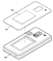
- FIGS. 8A to 8D are conceptual views illustrating a coupling relationship between a first body and a second body in accordance with an embodiment of the present invention.
- the mobile terminal 100 includes a second body 1120 corresponding to the terminal body and a first body 1110 for supplying light to the second body 1120.
- the mobile terminal is a bar type, a watch type that is formed to be worn like a watch, a clip type in which one body is coupled to another body like a clip, a folder type and a flip type in which one body is hinged to another body,
- One body may be a slide type or the like that slides relative to another body.
- the mobile terminal may be formed as a swivel type, a swing type, or an eyeglass type that is wearable like a goggle.
- any one body may be a first body 1110 having a light source, and the other body may be a second body 1120 having a film part.
- the first body 1110 may be detachably coupled to any one side of the second body 1120.
- the first body 1110 may be detachably coupled to provide various hologram images by replacing the first body 1110.
- the second body 1120 may include a coupling part 1130 to accommodate the first body 1110.
- the coupling part 1130 may be formed as a through hole formed in one side of the second body 1120, and the first body 1110 may be detachably coupled to the through hole.
- the through hole constituting the coupling part 1130 may be recessed sufficiently inward so that the first body 1110 to be coupled may not protrude to the outside of the second body 1120.
- Coupling unit 1130 may include a light control unit and a data transmission unit.
- the light control unit is formed to control light emitted from the first light source.
- the light control unit may be formed to be opened to allow light to pass therethrough, and may be closed to close the second body 1120 when the first body 1110 is separated.
- the data transmission unit electrically connects the first body 1110 and the second body 1120 to enable transmission and reception of signals.
- first body 1110 may be inclinedly coupled to the second body 1120.
- the first body 1110 may include at least one light source.
- the light source may be any one of lamps, lasers, or LEDs, or may be formed by combining two or more of these. Such a light source is just an example, and the light source may be formed including other units emitting light.
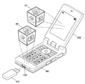
- the first body 1210 may be coupled to the inside of the second body 1220 from which the battery case 1221 is removed.
- the first body 1210 may be disposed to cover the battery or may be formed on the same plane as the battery.
- the first body 1310 may be integrally formed with the battery case 1321.
- the battery case 1321 When integrally formed in the battery case, not only the appearance of the terminal may be changed by replacing the battery case, but also various hologram images may be provided.
- the second body 1420 is a goggle that is wearable by a user, and the first body 1410 may be coupled to the second body 1420.
- the first body detachably coupled to the second body may provide a user with convenience and personalized appearance, in addition to providing a function to implement a hologram image. have.
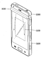
- 9A to 9B are diagrams illustrating operations of respective components of the mobile terminal according to the embodiments of the present invention.
- the first body 2110 is detachably coupled to the second body 2120 with at least one light source.
- the light source formed in the first body 2110 will be referred to as a first light source.
- the second body 2120 may include a film portion 2140 having an interference fringe so as to implement a holographic image.
- the film part 2140 may be formed to be replaceable through a slit penetrating the inside and the outside of the second body 2120.
- the film part 2140 may be slidably moved and detachably coupled to the second body 2120.
- the film portion 2140 may be formed to be flexible or at least partially fixed to the substrate.
- the film portion 2140 fixed on the substrate may reduce distortion of the image.
- the touch panel 2180 may be formed to cover the film portion 2140.
- the touch panel 2180 may be formed to include a transparent conductive pattern to sense a user's touch.
- the film part 2140 formed on the second body 2120 will be referred to as a first film part 2140.
- the second body 2120 may include a beam splitter 2121 formed to emit light supplied from the first light source in at least two directions.
- the optical separator 2121 may be formed to rotate at a predetermined angle to adjust a direction in which light is irradiated.
- the second body 2120 may include the first irradiator 2150 and the second irradiator 2160 such that light emitted through the optical separator 2121 may be irradiated at a predetermined angle toward one surface of the first film unit 2140. ) May be provided.
- the first irradiator 2150 and the second irradiator 2160 may include one or more optical mirrors.
- the following embodiments take an optical mirror as an example, but a prism having at least two optical planes may be used instead of the optical mirror.
- the first irradiator 2150 may include one mirror, and the second irradiator 2160 may include three mirrors to form a predetermined path.
- the mirror may be formed in a planar shape or include a part which is concave or convex. When at least a part of the mirror is formed to be concave or convex, the first film portion 2140 having a rectangular shape may be more effectively illuminated.
- the mirror may be formed including a diffractive optical element such as a holographic optical element (HOE) or a diffractive optical component (DOE).
- HOE holographic optical element
- DOE diffractive optical component
- the mirror may form an optical path from the first light source to the first film. That is, the path from the first light source through the light separator 2121 to the first film through the first irradiator 2150 forms a first path, and passes through the light separator 2121 from the first light source to the second irradiator ( The path to the first film via 2160 may form a second path.
- each of the first film part 2140, the first irradiation part 2150, or the second irradiation part 2160 is fixed, and the other end is formed to be rotatable about the one end and is irradiated to the first film part 2140.
- the angle of light can be adjusted.
- the first film part 2140 may be stacked to cover one surface of the display 2170.
- the display 2170 may be a second light source that emits light toward the first film portion 2140.
- the display 2170 may include, for example, a light emitting device such as AMOLED (Active Matrix Organic Light Emitting Diodes) when it is formed to be opaque. It may include a light emitting device.
- a light emitting device such as AMOLED (Active Matrix Organic Light Emitting Diodes) when it is formed to be opaque. It may include a light emitting device.
- the display 2170 When formed to be opaque, it may be coated with an optical member on one surface of the display 2170 to spray or reflect light toward the first film portion 2140.
- FIG. 9A illustrates an example of a mobile terminal when the display 2170 is opaque and FIG. 9B illustrates an example of a mobile terminal when the display 2270 is transparent.
- a reflector 2290 may be formed on the other surface of the display 2270 to reflect the incident light.
- 10A to 10E illustrate modified embodiments of the mobile terminal illustrated in FIG. 9.
- FIGS. 10A to 10E illustrate a case in which the display is configured as a transparent display
- at least some of the embodiments disclosed in FIGS. 10A to 10E may be applied to an opaque display.
- the same or similar configuration as that of the mobile terminal illustrated in FIG. 9 will be replaced with the foregoing description.
- the mobile terminal includes a first body 2310 and a second body 2320, and the first body 2310 is detachably coupled to the second body 2320.
- the first body 2310 may include at least one light source.
- the first body 2310 may include at least one film portion 2340.
- the film portion formed in the first body 2310 is called a second film portion.
- the light supplied from the first body 2310 to the second body 2320 is a hologram light formed by receiving a light from the first light source in the second film part embedded in the first body 2310.
- the second body 2320 may include at least one display 2370 and a film unit 2340, and an optical separator 2321 and an optical separator 2231 in which light supplied from the first body 2310 is separated.
- the first irradiator 2350 and the second irradiator 2360 may respectively include an optical path of the light emitted from the second irradiator.
- the second path may be a path from the first light source to the first film through the optical separator 2321 and through the second irradiator 2360.
- the light passing through the second path is reflected by the reflector 2290 disposed on the rear surface of the transparent display and is emitted toward a predetermined space on the display 2370.
- the predetermined space on the display 2370 is a space where a hologram image is formed.
- the first path extends from the first light source through the optical separator 2321 to the predetermined space on the display 2370 directly through the first irradiator 2350.
- the light via the first path and the light through the second path are combined with each other in a predetermined space on the display 2370 to realize a holographic composite image.
- the first irradiator 2350 may include a mirror and one lens to form a first path
- the second irradiator 2360 may include three lenses to form a second path.
- the first path extends from the first light source through the light splitter, through the first irradiator 2450, and directly to a predetermined space on the display 2470.
- the second path is directed from the first light source through the light splitter to the first film through the second irradiator 2460, and is reflected by the reflector to extend to a predetermined space on the display 2470.
- the light via the first path and the light through the second path are combined with each other in a predetermined space on the display 2470 to realize a hologram composite image.
- the first irradiator 2450 may include a mirror and one lens to form a first path
- the second irradiator 2460 may include a lens to form a second path.
- the light separator and the reflector may be integrally formed and formed on the rear surface of the display 2470.
- the terminal can be made slimmer and the manufacturing process can be simplified.
- a portion in which the optical splitter and the reflector are integrally formed will be referred to as a separation composite part 2490.
- the first body 2510 may be coupled to any one side of the second body 2520.
- the separation compound part 2590 may be integrally formed including the light separator and the reflection part, and disposed on the rear surface of the display 2570.
- the first path passes from the first light source through the light splitter and passes through the display 2570, the first film portion 2540, and the lens 2571 to one surface of the display 2570. Extends to the phase.
- the second path passes through the optical splitter 2521 from the first light source, passes through the display 2570, the first film portion 2540, and the reflective sheet 2258, and then irradiates the first film portion 2540 and is reflected. After passing through the portion 2290, it extends over one surface of the display 2570.
- the light via the first path and the light through the second path are combined with each other in a predetermined space on the display 2570 to realize a holographic composite image.
- the touch panel 2580 covering the first film part 2540 may include a lens 2571 and a reflective sheet 2258.
- the reflective sheet 2252 may be formed so that incident light irradiates a predetermined region of the first film portion 2540.
- the first body 2610 may be coupled to one side of the second body 2620.
- the separation compound part 2690 may be integrally formed including the light separator and the reflection part and disposed on the rear surface of the display 2670.
- the optical splitter 2621 includes a first optical splitter that separates the light supplied from the first light source into a first light and a second light, and second optical splitters that split the first and second light into at least two lights, respectively. It may include.
- At least four light paths may be included.
- the first path passes from the first light source through the first optical splitter and any one second optical splitter, through the display 2670, the first film portion 2640, and the lens 2701 to display 2670. It extends to one side of.
- the second path passes through the first optical splitter and the second optical splitter from the first light source, passes through the display 2670, the first film portion 2640, and the reflective sheet 2268, and then returns to the first film portion 2640. Is irradiated to the surface of the display 2670 and passes through the reflector.
- the third path passes through the display 2670, the first film part 2640, and the lens 2701 from the first light source, through the second optical splitter different from the first optical splitter, and to one surface of the display 2670. Extends to the phase.
- the second path passes through the first optical splitter and the second optical splitter from the first light source, passes through the display 2670, the first film portion 2640, and the reflective sheet 2268, and then returns to the first film portion 2640. Is irradiated to the surface of the display 2670 and passes through the reflector.
- the light via the first path and the light through the second path are combined with each other in a predetermined space (eg, the first space) on the display 2670 to realize the first hologram composite image.
- the second hologram composite image may be realized by combining the light passing through the third path and the light passing through the fourth path in another predetermined space (eg, the second space) on the display 2670.
- the embodiment illustrated in FIG. 10D may implement at least two holographic composite images.
- the first body 2710 may be coupled to any one side of the second body 2720.
- the separation composite part 2790 may be integrally formed including an optical separator and a reflection part.
- the first display 2770 and the second display 2770 ′ are formed to cover one side and the other side of the separation composite unit 2790, respectively.
- the first film portions 2740 and 2740 ′ may be disposed on other surfaces of the first display 2770 and the second display 2770 ′ that do not face the separation composite part.
- the touch panels 2780 and 2780 'covering the first film parts 2740 and 2740' may include lenses 281 and 2781 'and reflective sheets 2782 and 2782'.
- the reflective sheets 2782 and 2782 ' may be formed so that incident light irradiates a predetermined area of the first film portions 2740 and 2740'.
- the optical splitter may include a first optical splitter that separates the light supplied from the first light source into first and second lights, and second optical splitters that split the first and second lights into at least two lights, respectively. have.
- the embodiment shown in FIG. 10E may include at least eight optical paths.
- the first path extends from the first light source, through the first optical separator and any one second optical splitter, through the first display, the first film portion, and the lens onto one surface of the first display.
- the second path passes through the first optical splitter and the second optical splitter from the first light source, passes through the first display, the first film part and the reflective sheet, and then irradiates the first film part again and passes through the reflecting part. It extends over one side of the display.
- the light through the first path and the light through the second path are combined with each other in a predetermined space (eg, the first space) on the display to realize the first hologram composite image.
- a predetermined space eg, the first space
- the other paths except for the first path and the second path have similar optical paths. As a result, at least four holographic composite images can be implemented.
- 11 to 12 are conceptual diagrams illustrating an example of a mobile terminal displaying a plurality of holograms.
- the same or similar configuration as that of the mobile terminal illustrated in FIG. 9 will be replaced with the foregoing description.
- the first body 3110 constituting the mobile terminal is detachably coupled to one side of the second body 3120.
- the first body 3110 may include at least one light source and a film unit 3140 to form a hologram image. Some of the hologram light formed in the first body 3110 is radiated outward through an opening formed in the first body 3110 to form a hologram image, and the other of the hologram light is supplied to the second body 3120.
- the second body 2120 includes a display, a film part, a light separator, and irradiators, and receives hologram light from the first body to form a hologram image on one surface of the second body.
- the first body 3110 and the second body 3120 may form different or identical holographic images, respectively.
- the mobile terminal may be formed in a folder type.
- the main body portion and the folder portion are hinged to overlap each other.
- the first body 4110 having a light source may be coupled to a main body or a folder part.
- the first body 4110 may include a film part and a mirror to form a holographic image, and may supply the hologram light passing through the film part to the combined main body part or the folder part.
- Either of the folder portion 4002 or the main body portion 4001 may have a film portion and irradiation portions.
- any one of the folder portion or the main body portion may be provided with an optical separator. For this reason, the light may be irradiated to the film unit using light supplied from the first body, and then a holographic image may be formed.
- the first hologram image 416 is formed by the first body 4110 coupled to the main body, and the holographic light is supplied to the folder portion from the first body, and the film portion and the irradiation portion are provided. As a result, the second hologram image 415 may be formed.
- the first hologram image and the second hologram image may be combined with each other to form a hologram composite image.
- FIG. 13 is a conceptual diagram illustrating an example of forming a hologram image in a clamshell terminal.
- the same or similar configuration as that of the mobile terminal illustrated in FIG. 9 will be replaced with the foregoing description.
- the first body (not shown) is detachably coupled to the second body 5001.
- One side of the second body 5001 is formed with a third body 5110 which is hinged to the second body 5001.
- the first body has a light source and is formed to supply light to the second body 2120.
- the second body includes irradiation parts to irradiate light toward the third body.
- the third body may include a film unit to form a holographic image when light is irradiated from the second body. In this way, when the film portion is formed in the third body, replacement of the film portion is easier.
- different hologram images may be formed according to the inclination angle of the third body.
- the hologram image may be applied to a flip terminal.
- FIGS. 14A to 22C a second type of mobile terminals, in which one of a light source and an irradiator, move relative to the other as a mobile terminal for generating a hologram image, will be described.
- the film unit 11110, the light source 11121, and the irradiation unit 11122 may be disposed on the terminal body 11100.
- the film portion 11110 may include an interference fringe so as to implement a holographic image.
- the film portion 11110 may be formed to be replaceable through slits that penetrate the inside and the outside of the body.
- the film portion 11110 may be formed to be slidably movable and detachably coupled to the body. As such, by replacing the film part 11110, more various holographic images may be realized.
- the film portion 11110 may be formed to be flexible or at least partially fixed to the substrate.
- the film portion 11110 fixed on the substrate may reduce distortion of the image.
- the touch panel may be formed to cover the film portion 11110.
- the touch panel may be formed to include a transparent conductive pattern to sense a user's touch.
- the light source 11121 may be any one of a lamp, a laser, and an LED, or may be formed by combining two or more thereof.
- the light source 11121 is only an example, and the light source 11121 may be formed including other units emitting light.
- the irradiator 11122 may be formed so that light emitted from the light source 11121 may be irradiated at an angle toward one surface of the film portion 11110.
- the irradiator 11122 may include one or more optical mirrors.
- the following embodiments take an optical mirror as an example, but a prism having at least two optical planes may be used instead of the optical mirror.
- the mirror may be formed in a planar shape or include a part which is concave or convex. When at least a part of the mirror is concave or convex, the rectangular film portion 11110 may be more effectively illuminated.
- the mirror may be formed including a diffractive optical element such as a holographic optical element (HOE) or a diffractive optical component (DOE).
- HOE holographic optical element
- DOE diffractive optical component
- the irradiation part 11122 and the light source 11121 may be integrally formed as one optical module 11120.
- the distance between the irradiation unit 11122 and the light source 11121 may be adjusted, and the irradiation unit 11122 and the light source 11121 are formed to be angle adjustable, respectively, to more effectively control the light directed toward the film unit 11110. Can be.
- a display is formed to cover at least a part of the film part 1112.
- the display may be another light source 1121 to emit light toward the film part 1112.
- the display may include a light emitting device such as AMOLED (Active Matrix Organic Light Emitting Diodes), and when the display is transparent, for example, a light emitting device such as Top-Emitting Organic Light Emitting Diode (TOLED) It may include.
- AMOLED Active Matrix Organic Light Emitting Diodes
- TOLED Top-Emitting Organic Light Emitting Diode
- When formed opaque it may be coated with an optical member to spray or reflect light toward the film portion 1112 on one surface of the display.
- a reflective part is formed on the other surface of the display to reflect the incident light.
- 15A to 15B are views illustrating an example of a film part that is formed to be adjustable in angle in connection with an embodiment of the present invention.
- the film part 11310 is formed to be relatively movable with respect to the irradiation part 11322 in the main body. Different hologram images may be formed according to angles of light irradiated onto one surface of the film part 11310.
- the hologram pattern formed on the film part 1113 may be formed to output the first hologram image at the first irradiation angle, and may be formed to output the second hologram image at the second irradiation angle. That is, the film unit 11310 may include a plurality of hologram patterns to output different hologram images according to angles.
- the angle of the irradiation unit 11322 and the angle of the film unit 1113 may be adjusted to adjust the irradiation angle.
- a hinge is formed at one end of the film part 1113, and is rotatably formed around the hinge, or a shaft is connected to any part of the film part 1113, and the axis is centered. It can be formed to be rotatable.
- a hinge is formed at one end of the irradiator 1112, and is formed to be rotatable around the hinge, or a shaft is connected to any part of the irradiator 1112, and the axis is centered. It can be formed to be rotatable.
- the irradiation part 11322 may be rotatably formed as a whole, as shown in FIG. 15A, or a portion of the irradiation part 1112 may be rotatably formed as shown in FIG. 15B.
- 16A to 16B illustrate an optical module 1520 that is rotatably formed with respect to a body in accordance with an embodiment of the present invention.
- the optical module 1520 may be rotatably coupled to one end of the terminal body (11500).
- the terminal body 11500 and the optical module 11520 may be hinged.
- FIG. 16A shows the state before rotation
- FIG. 16B shows the state after rotation.
- light may be irradiated to one surface of the main body to form a hologram image.
- a film portion On one surface of the body is formed a film portion (11510).
- the film unit 10110 may include a plurality of hologram patterns to output different hologram images according to angles.
- the angle of rotation of the optical module 11520 facing the film unit 1115 is formed to be adjustable, and the film unit 1115 may also be formed to be angle-adjustable.
- the degree of rotation of the optical module 1520 may be adjusted to form different hologram images according to the angle of rotation of the optical module 11520.
- at least one hologram image may be formed as a space on one surface of the main body.
- 17A to 17B are conceptual views illustrating an example of arrangement of an optical module 12120 and a film unit 12110 in a slide type terminal in accordance with an embodiment of the present invention.
- the second body 12200 having a display and the first body 12100 having a keypad formed on one surface thereof are formed to realize a closed state and an open state. As shown, any one body may be formed to be slideable relative to the other body.
- the film unit 12110 may be formed to receive light from the optical module 12120 and the optical module 12120 in a predetermined region of the first body 12100 except for the region where the keypad is disposed.
- the first body 12100 may include a receiving portion to insert the optical module 12120.
- the optical module 12120 may be formed to enter or exit the accommodating portion, and may be formed to protrude by a predetermined height onto one surface of the first body 12100 in an open state.
- the optical module 12120 may be formed to be slidably moved along the inner circumferential surface of the accommodation portion.
- Protruding heights of the optical module 12120 may be formed differently, and the optical module 12120 may be fixed to a certain height. Depending on the height of the optical module 12120, the angle at which the irradiation part 12122 irradiates the film part 12110 may be different.
- the film unit 12110 may include a plurality of hologram patterns to output different hologram images according to angles.
- the height of the optical module 12120 may be adjusted to form different holographic images.
- at least one hologram image may be formed as a space on one surface of the terminal.
- the optical module 12120 is in a second direction, that is, in a thickness direction that replaces the first direction. It may be formed to be movable.
- 18A to 18D are conceptual views illustrating a change of a portion to which light is irradiated due to a slide movement in relation to an embodiment of the present invention.
- the first body 13100 and the second body 13200 are formed to implement a closed state and an open state.
- the second body 13200 may be formed to be accommodated in a groove formed in the first body 13100.
- the second body 13200 may be formed to be slidably movable with respect to the first body 13100.
- the film part 13110 may be formed on one surface of the first body 13100.
- the second body 13200 may include a receiving unit to insert the optical module 13120.
- the optical module 13120 may be formed to enter or exit the accommodating portion, and may be formed to protrude by a predetermined height onto one surface of the second body 13200 in an open state.
- Protruding heights of the optical module 13120 may be formed differently, and the optical module 13120 may be fixed to a predetermined height. Depending on the height of the optical module 13120, the angle at which the irradiation part 13122 irradiates the film part 13110 may be different.
- the film unit 13110 may include a plurality of hologram patterns to output different hologram images according to angles.
- the distance between the first body 13100 and the second body 13200 is determined.
- the angle of light irradiated onto the film part 13110 may vary.
- the first body 13100 and the second body 13200 may be fixed at a distance spaced by a predetermined distance.
- the film part 13110 may include a plurality of hologram patterns to output different hologram images according to distances between the first body 13100 and the second body 13200.
- the size of the first body 13100 and the second body 13200 may vary depending on the distance from each other, even if they are the same holographic image.
- 19A to 19B are conceptual views illustrating an example of a mobile terminal formed to implement a closed state and an open state in accordance with an embodiment of the present invention.
- the first body 14100 and the second body 14200 are formed to implement a closed state and an open state. As shown in FIG. 19A, the first body 14100 and the second body 14200 may be formed to swivel. That is, the first body 14100 may slide along one axis of the second body 14200 along the axis formed in the second body 14200. In this case, the first body 14100 and the second body 14200 may be coupled to each other by a hinge module.
- first body 15100 and the second body 15200 may be formed such that one body is slidably movable relative to the other body.
- first body 15100 and the second body 15200 may be coupled to each other by a slide module.
- the first body 15100 may include a display, and the film unit 15110 may be formed in a predetermined region of the second body 15200.
- the optical module 15120 is disposed in close proximity to irradiate the film unit 15110.
- the optical module 15120 may be formed to enter or exit the accommodation portion of the second body 15200.
- the optical module 15120 may be formed to protrude by a predetermined height onto one surface of the second body 15200 in an open state.
- Protruding heights of the optical module 15120 may be different from each other, and may be formed so that the optical module 15120 is fixed in a state of protruding by a predetermined height.
- the angle at which the irradiator 15122 irradiates the film unit 15110 may vary depending on the height of the optical module 15120.
- the film unit 15110 may include a plurality of hologram patterns to output different hologram images according to angles.
- 20A to 22C are conceptual views illustrating an example of a mobile terminal formed to reduce or eliminate interference between a body and a film portion.
- the first body 16100 and the second body 16200 are formed to implement a closed state and an open state.
- the second body 16200 may be formed to be accommodated in a groove formed in the first body 16100.
- the second body 16200 may be formed to be slidably movable with respect to the first body 16100.
- the second body 16200 includes a hologram module for forming a hologram image.
- the hologram module may include a film unit, and may include an irradiation unit and a light source.
- the hologram image irradiated from the second body 16200 may be partially blocked by the first body 16100 and may be interfered.
- the first body 16100 or the second body 16200 may be formed to be tiltable.
- the film portion 16110 may be tilted to prevent such interference.
- the hologram module may be hinged to the terminal body so as not to interfere with the terminal body.
- the hologram module may include a film unit, and may include an irradiation unit and a light source.
- the hologram module may be coupled to the terminal body by a hinge module.
- the first body 18100 and the second body 18200 are formed to implement a closed state and an open state.
- the first body 18100 and the second body 18200 may be formed such that one body is slidably movable with respect to the other body.
- the first body 18100 and the second body 18200 may be coupled to each other by a slide module.
- the first body 18100 includes a hologram module that forms a hologram image.
- the hologram module may include a film unit, and may include an irradiation unit and a light source.
- the hologram image is projected onto one surface of the first body 18100, and the hologram light projected by the second body 18200 may be blocked.
- the second body 18801 may be formed to be tiltable. As a result, it is possible to eliminate or reduce interference of the second body 18801 with the hologram light formed from the first body 18101.
- the shape of a portion of the second body 18202 may be changed to reduce interference of the second body 18202. This may eliminate or reduce interference of the second body 18102 with the hologram light formed from the first body 18102.
- the above-described mobile terminal is not limited to the configuration and method of the above-described embodiments, but the embodiments may be configured by selectively combining all or some of the embodiments so that various modifications can be made. It may be.
- Embodiments of the present invention propose a method of implementing a holographic image in a mobile terminal, and thus may be applied to various industrial fields related thereto.
Landscapes
- Physics & Mathematics (AREA)
- General Physics & Mathematics (AREA)
- Engineering & Computer Science (AREA)
- Geometry (AREA)
- Multimedia (AREA)
- Signal Processing (AREA)
- Computer Graphics (AREA)
- Software Systems (AREA)
- Theoretical Computer Science (AREA)
- Telephone Function (AREA)
- Telephone Set Structure (AREA)
Abstract
본 발명의 일 실시예에 따르는 이동 단말기는, 착탈가능하게 서로 결합되는 제1 바디와 제2 바디와, 상기 제2 바디에 빛을 공급하도록 상기 제1 바디에 형성되는 제1 광원 및 상기 제2 바디에 형성되고, 상기 제1 광원으로부터 빛을 공급받아 제1 홀로그램 영상을 형성하는 제1 필름부를 포함함으로써, 제1 바디를 교체함으로써 보다 다양한 홀로그램 영상을 출력할 수 있다.
Description
본 발명의 일실시예들은 홀로그램 영상을 출력할 수 있는 이동 단말기에 관한 것이다.
단말기(terminal)는 기능이 다양화됨에 따라 예를 들어, 사진이나 동영상의 촬영, 음악이나 동영상 파일의 재생, 게임, 방송의 수신 등의 복합적인 기능들을 갖춘 멀티미디어 기기(Multimedia player) 형태로 구현되고 있다.
단말기는 이동 가능 여부에 따라 휴대용 단말기(mobile/portable terminal) 및 고정 단말기(stationary terminal)으로 나뉠 수 있다. 휴대용 단말기는 휴대가 가능하면서 음성 및 영상 통화를 수행할 수 있는 기능, 정보를 입·출력할 수 있는 기능 및 데이터를 저장할 수 있는 기능 등을 하나 이상 갖춘 휴대용 기기이다.
이러한 단말기의 기능 지지 및 증대를 위해, 단말기의 구조적인 부분 및/또는 소프트웨어적인 부분을 개량하는 것이 고려될 수 있다.
단말기의 기능의 확장 방안으로서 홀로그램 영상을 표시할 수 있는 단말기가 고려될 수 있다. 이에 따라 홀로그램 영상의 출력 방안으로서, 다양한 시도들이 행해지고 있다.
따라서, 다양한 홀로그램을 형성할 수 있으면서도, 보다 컴팩트하게 이동 단말기에 장착될 수 있는 홀로그램 장치가 고려될 수 있다.
본 발명의 일 목적은 기존과는 다른 형태의 단말기로서, 제1 바디와 제2 바디가 서로 결합하여 홀로그램 영상을 출력할 수 있는 이동 단말기를 제공하기 위한 것이다.
본 발명의 다른 목적은, 보다 향상된 구조를 갖으며, 복합적인 기능을 갖는 홀로그램 표시 장치를 구비하는 이동 단말기를 제공하기 위한 것이다.
이와 같은 본 발명의 해결 과제를 달성하기 위하여, 본 발명의 일 실시예에 따르는 이동 단말기는, 착탈가능하게 서로 결합되는 제1 바디와 제2 바디와, 상기 제2 바디에 빛을 공급하도록 상기 제1 바디에 형성되는 제1 광원 및 상기 제2 바디에 형성되고, 상기 제1 광원으로부터 빛을 공급받아 제1 홀로그램 영상을 형성하는 제1 필름부를 포함한다.
본 발명과 관련한 일 예에 따르면, 상기 제1 바디와 제2 바디가 서로 결합하는 결합부는 상기 제1 광원으로부터 방사되는 빛을 조절할 수 있도록 형성되는 광조절부를 구비할 수 있다.
본 발명과 관련한 일 예에 따르면, 상기 제1 광원은 램프, 레이저 또는 LED 중 적어도 어느 하나를 포함할 수 있다.
본 발명과 관련한 일 예에 따르면, 상기 제2 바디는 상기 제1 광원으로부터 공급되는 빛을 적어도 두 방향으로 방사하도록 형성되는 광분리기를 더 포함할 수 있다.
본 발명과 관련한 일 예에 따르면, 상기 제2 바디는, 상기 방사된 광들을 상기 제1 필름부의 일면을 향하여 각각 조사하는 제1 조사부와 제2 조사부를 더 포함할 수 있다.
본 발명과 관련한 일 예에 따르면, 상기 제1 필름부, 제1 조사부 또는 제2 조사부 중 적어도 하나는 일단이 고정되고, 타단은 상기 일단을 중심으로 회동가능하게 형성될 수 있다.
본 발명과 관련한 일 예에 따르면, 상기 제1 필름부의 배면에 배치되고, 상기 제1 필름부를 투과하여 광을 방사하도록 형성되는 제2 광원을 더 포함할 수 있다.
본 발명과 관련한 일 예에 따르면, 상기 제2 광원은 투명 디스플레이로 형성될 수 있다.
본 발명과 관련한 일 예에 따르면, 상기 투명 디스플레이를 덮도록 반사부가 형성될 수 있다.
본 발명과 관련한 일 예에 따르면, 상기 투명 디스플레이와 상기 반사부 사이에 적어도 하나의 렌즈가 배치될 수 있다.
본 발명과 관련한 일 예에 따르면, 상기 반사부는, 일단이 고정되고, 타단은 상기 일단을 중심으로 회동가능하게 형성될 수 있다.
본 발명과 관련한 일 예에 따르면, 상기 제1 바디는 상기 제1 광원으로부터 빛을 공급받아 제2 홀로그램 영상을 형성하는 제2 필름부를 포함할 수 있다.
본 발명과 관련한 일 예에 따르면, 상기 제1 필름부는 교체가능하게 상기 제2 바디에 장착될 수 있다.
또한 상기한 과제를 실현하기 위하여 본 발명의 다른 실시예는, 착탈가능하게 서로 결합되는 제1 바디와 제2 바디, 상기 제2 바디에 빛을 공급하도록 상기 제1 바디에 형성되는 제1 광원과, 상기 제1 광원으로부터 공급되는 빛을 적어도 두 방향으로 방사하도록 형성되는 광분리기 및 상기 제2 바디에 장착되고, 상기 광분리기를 통해 방사된 어느 하나의 광을 공급받아 홀로그램 영상을 형성하는 제1 필름부를 포함하고, 상기 광분리기로 공급되는 빛은, 상기 제1 바디에 내장된 제2 필름부로 인해 형성된 홀로그램 광인 것을 특징으로 하는 이동 단말기를 개시한다.
본 발명과 관련한 일 예에 따르면, 상기 광분리기로 인해 제1광과 제2광으로 분리되고, 상기 제1광은 상기 제2 바디의 일면 상으로 방사되고, 상기 제2광은 상기 제1 필름부에 조사된 후 상기 제2 바디의 일면 상으로 반사되고, 상기 제1광과 상기 제1 필름부로부터 반사되는 광이 서로 조합되어 홀로그램 복합 영상을 형성할 수 있다.
본 발명과 관련한 일 예에 따르면, 상기 제1 필름부의 배면에 배치되고, 상기 제1 필름부를 투과하여 광을 방사하도록 형성되는 제2 광원을 더 포함할 수 있다.
본 발명과 관련한 일 예에 따르면, 상기 광분리기는, 상기 제1 광원으로부터 공급되는 빛을 제1광과 제2광으로 분리하는 제1 광분리기 및 상기 제1광과 제2광을 각각 적어도 두 개의 광으로 분리하는 제2 광분리기들을 포함할 수 있다.
본 발명과 관련한 일 예에 따르면, 상기 제2 광분리기들로부터 분리된 광들 중 적어도 어느 하나는 상기 제2 바디의 일면 상으로 방사되고, 적어도 다른 하나는 상기 제1 필름부에 조사된 후 상기 제2 바디의 일면 상으로 반사되고, 상기 광들이 상기 제2 바디의 일면 상에서 서로 조합되어 하나 이상의 홀로그램 복합 영상을 형성할 수 있다.
또한 상기한 과제를 실현하기 위하여 본 발명의 또 다른 실시예는, 착탈가능하게 서로 결합되는 제1 바디와 제2 바디, 상기 제2 바디에 빛을 공급하도록 상기 제1 바디에 형성되는 제1 광원과, 상기 제1 광원으로부터 공급되는 빛을 적어도 두 방향으로 방사하도록 형성되는 광분리기와, 상기 광분리기를 통해 방사된 어느 하나의 광을 공급받아 홀로그램 영상을 형성하는 제1 필름부와 제3 필름부 및 상기 광분리기와 필름부들 사이에 각각 배치되는 제2 광원들을 포함하고, 상기 제2 바디의 일면에 제1 홀로그램 영상이 형성되고, 타면에 제2 홀로그램 영상이 형성되는 이동 단말기를 개시한다.
또한 상기한 과제를 실현하기 위하여 본 발명의 다른 실시예는, 단말기 본체와, 상기 본체에 장착되고, 광이 방사(radiation)되면 홀로그램 영상을 형성하는 필름부와, 상기 필름부에 상기 광을 방사하도록 형성되는 조사부 및 상기 조사부로 광을 공급하는 광원을 포함하고, 상기 조사부는, 상기 필름부의 일면에 대한 광의 방사를 조절할 수 있도록 상기 필름부에 대하여 상대 이동가능하게 형성되는 이동 단말기를 개시한다.
본 발명과 관련한 일 예에 따르면, 상기 조사부와 상기 광원이 일체로 광 모듈을 형성하고, 상기 광 모듈은 상기 필름부의 일면에 대한 광의 방사를 조절할 수 있도록 상기 본체에 대하여 슬라이드 이동가능하게 형성될 수 있다.
본 발명과 관련한 일 예에 따르면, 상기 광 모듈은, 제1 방향으로 연장된 상기 본체에 대하여 상기 제1 방향과 교차하는 제2 방향으로 슬라이드 이동 가능하게 형성될 수 있다.
본 발명과 관련한 일 예에 따르면, 상기 슬라이드 이동 거리에 따라 상기 필름부에 대한 광원 및 조사부의 광 방사가 제어되어 상기 홀로그램 영상의 크기를 조절할 수 있다.
본 발명과 관련한 일 예에 따르면, 상기 조사부와 상기 광원이 일체로 광 모듈을 형성하고, 상기 광 모듈은 상기 본체에 대하여 회동 가능하도록 힌지 결합될 수 있다.
본 발명과 관련한 일 예에 따르면, 상기 필름부의 배면에 배치되고, 상기 필름부를 투과하여 광을 방사하도록 형성되는 디스플레이를 더 포함할 수 있다.
본 발명과 관련한 일 예에 따르면, 상기 디스플레이는 투명 디스플레이로 형성될 수 있다.
또한 상기한 과제를 실현하기 위하여 본 발명의 다른 실시예는, 닫힌 상태와 열린 상태를 구현할 수 있도록 상대 이동 가능하게 결합되는 제1 바디와 제2 바디, 상기 제2 바디에 장착되고, 광이 방사(radiation)되면 홀로그램 영상을 형성하는 필름부 및 상기 필름부에 상기 광을 방사하도록 광원과 조사부를 구비하는 광 모듈을 포함하고, 상기 광 모듈은, 상기 열린 상태에서, 상기 제2 바디로부터 돌출가능하게 형성되고, 상기 필름부의 일면에 대한 광의 방사를 조절할 수 있도록 상기 필름부에 대하여 상대 이동가능하게 형성되는 이동 단말기를 개시한다.
본 발명과 관련한 일 예에 따르면, 상기 광 모듈은, 제1 방향으로 연장된 상기 제2 바디에 대하여 상기 제1 방향과 교차하는 제2 방향으로 이동 가능하게 형성될 수 있다.
본 발명과 관련한 일 예에 따르면, 상기 광 모듈의 이동 거리에 따라 상기 필름부에 대한 광원 및 조사부의 광 방사가 제어되어 상기 홀로그램 영상의 크기를 조절할 수 있다.
본 발명과 관련한 일 예에 따르면, 상기 광 모듈의 이동 거리에 따라 상기 필름부에 대한 광원 및 조사부의 광 방사가 제어되어 각각 다른 상기 홀로그램 영상을 형성할 수 있다.
본 발명과 관련한 일 예에 따르면, 상기 제2 바디는 상기 광 모듈이 삽입되는 수용부를 구비하고, 상기 제1 바디와 제2 바디의 상대 이동에 따라 상기 광 모듈이 상기 수용부로부터 돌출되거나 상기 수용부로 삽입될 수 있다.
본 발명과 관련한 일 예에 따르면, 상기 제1 바디는 디스플레이를 구비하고, 열린 상태에서 상기 제2 바디의 일면 상에 상기 홀로그램 영상이 표시될 수 있다.
본 발명과 관련한 일 예에 따르면, 상기 상대 이동은 상기 제1 바디와 상기 제2 바디가 슬라이드 모듈에 의해 서로 결합되어, 어느 하나의 바디가 다른 바디에 대해 슬라이드 이동할 수 있다.
본 발명과 관련한 일 예에 따르면, 상기 상대 이동은 상기 제1 바디와 상기 제2 바디가 힌지 모듈에 의해 서로 결합되어, 어느 하나의 바디가 다른 바디에 대해 회전 이동할 수 있다.
또한 상기한 과제를 실현하기 위하여 본 발명의 다른 실시예는, 닫힌 상태와 열린 상태를 구현할 수 있도록 상대 이동 가능하게 결합되는 제1 바디와 제2 바디 및 상기 제2 바디에 장착되고, 광이 방사(radiation)되면 홀로그램 영상을 형성하는 필름부, 상기 필름부에 상기 광을 방사하도록 광원과 조사부를 구비하는 홀로그램 모듈을 포함하고, 상기 열린 상태에서 상기 제1 바디에 의해 홀로그램 영상이 간섭되는 것을 방지하기 위해, 상기 필름부로부터 방사되는 광이 상기 제1 바디에 의해 덮이지 않도록 형성되는 이동 단말기를 개시한다.
본 발명과 관련한 일 예에 따르면, 상기 제1 바디는 틸팅가능하게 형성될 수 있다.
본 발명과 관련한 일 예에 따르면, 상기 필름부는 틸팅가능하게 형성될 수 있다.
또한 상기한 과제를 실현하기 위하여 본 발명의 다른 실시예는, 단말기 본체와, 상기 본체에 장착되고, 광이 방사(radiation)되면 홀로그램 영상을 형성하는 필름부와, 상기 필름부에 상기 광을 방사하도록 형성되는 조사부 및 상기 조사부로 광을 공급하는 광원을 포함하고, 상기 본체의 어느 일면 상으로 투사되는 홀로그램 영상을 조절하도록 상기 필름부는 이동가능하게 형성되는 이동 단말기를 개시한다.
본 발명과 관련한 일 예에 따르면, 상기 필름부의 이동에 대응하여 상기 조사부는 이동가능하게 형성될 수 있다.
상기와 같이 구성되는 본 발명의 적어도 하나의 실시예에 관련된 이동 단말기는 제1 바디가 착탈가능하게 제2 바디에 결합되므로, 제1 바디를 교체함으로써 보다 다양한 홀로그램 영상을 출력할 수 있다.
또한, 이동 단말기는 단말기를 구성하는 각 기구물이 서로 겹쳐지는 상태에서, 보다 원활하게 홀로그램 영상을 출력할 수 있다.
도 1은 본 발명의 일 실시예와 관련된 이동 단말기의 블록 구성도(block diagram).
도 2는 본 발명의 일 실시예에 관련된 이동 단말기의 전면 사시도.
도 3은 본 발명과 관련된 이동 단말기의 일 작동 상태를 설명하기 위한 이동 단말기의 정면도.
도 4는 본 발명의 일 실시예와 관련하여 홀로그래피 모듈을 포함하는 이동 단말기를 나타내는 도면.
도 5는 홀로그래피 원리를 설명하기 위한 개념도.
도 6은 투과형 홀로그래피 방식을 설명하기 위한 개념도.
도 7은 반사형 홀로그래피 방식을 설명하기 위한 개념도.
도 8a 내지 도 8d는 본 발명의 일 실시예와 관련하여, 제1 바디와 제2 바디의 결합관계를 도시한 개념도들.
도 9a 내지 도 9b는 본 발명의 실시예들에 따르는 이동 단말기의 각 구성의 동작을 도시한 도면들.
도 10a 내지 도 10e는 도 9a 내지 도 9b에 도시한 이동 단말기의 변형 실시예들.
도 11 내지 도 12는 복수의 홀로그램을 표시하는 이동 단말기의 일 예를 도시한 개념도들.
도 13은 폴더형 단말기에서 홀로그램 영상을 형성하는 일 예를 도시한 개념도.
도 14a 내지 도 14b는 본 발명의 실시예와 관련하여 이동 단말기에 배치되는 광 모듈과 필름부를 도시한 개념도들.
도 15a 내지 도 15b는 본 발명의 실시예와 관련하여 각도 조절가능하게 형성되는 필름부의 일 예를 도시한 도면들.
도 16a 내지 도 16b는 본 발명의 실시예와 관련하여 본체에 대하여 회동가능하게 형성되는 광 모듈을 도시한 도면들.
도 17a 내지 도 17b는 본 발명의 실시예와 관련하여 슬라이드 타입 단말기에서 광 모듈과 필름부의 배치에 관한 일 예를 도시한 개념도들.
도 18a 내지 도 18d는 본 발명의 실시예와 관련하여, 슬라이드 이동에 따른 광이 조사되는 부분의 변화를 도시한 개념도들.
도 19a 내지 도 19b는 본 발명의 실시예와 관련하여, 닫힌 상태와 열린 상태를 구현할 수 있도록 형성되는 이동 단말기의 일 예를 도시한 개념도들.
도 20a 내지 도 22c는 바디와 필름부간의 간섭을 줄이거나 없앨 수 있도록 형성되는 이동 단말기의 일 예를 도시한 개념도들.
이하, 본 발명에 관련된 이동 단말기에 대하여 도면을 참조하여 보다 상세하게 설명한다. 이하의 설명에서 사용되는 구성요소에 대한 접미사 "모듈" 및 "부"는 명세서 작성의 용이함만이 고려되어 부여되거나 혼용되는 것으로서, 그 자체로 서로 구별되는 의미 또는 역할을 갖는 것은 아니다. 본 명세서에서는 서로 다른 실시예라도 동일·유사한 구성에 대해서는 동일·유사한 참조번호를 부여하고, 그 설명은 처음 설명으로 갈음한다. 본 명세서에서 사용되는 단수의 표현은 문맥상 명백하게 다르게 뜻하지 않는 한, 복수의 표현을 포함한다.
본 명세서에서 설명되는 이동 단말기에는 휴대폰, 스마트 폰(smart phone), 노트북 컴퓨터(laptop computer), 디지털방송용 단말기, PDA(Personal Digital Assistants), PMP(Portable Multimedia Player), 네비게이션 등이 포함될 수 있다. 다만, 본 명세서에서 설명되는 기술사상은 디지털 TV, 데스크탑 컴퓨터 등과 같은 고정 단말기에도 적용이 가능하다.
전체구성
도 1은 본 발명의 일 실시예와 관련된 이동 단말기의 블록 구성도(block diagram)이다.
상기 이동 단말기(100)는 무선 통신부(110), A/V(Audio/Video) 입력부(120), 사용자 입력부(130), 센싱부(140), 출력부(150), 메모리(160), 인터페이스부(170), 제어부(180) 및 전원 공급부(190) 등을 포함할 수 있다. 도 1에 도시된 구성요소들이 필수적인 것은 아니어서, 그보다 많은 구성요소들을 갖거나 그보다 적은 구성요소들을 갖는 이동 단말기가 구현될 수도 있다.
이하, 상기 구성요소들에 대해 차례로 살펴본다.
무선 통신부(110)는 이동 단말기(100)와 무선 통신 시스템 사이 또는 이동 단말기(100)와 이동 단말기(100)가 위치한 네트워크 사이의 무선 통신을 가능하게 하는 하나 이상의 모듈을 포함할 수 있다. 예를 들어, 무선 통신부(110)는 방송 수신 모듈(111), 이동통신 모듈(112), 무선 인터넷 모듈(113), 근거리 통신 모듈(114) 및 위치정보 모듈(115) 등을 포함할 수 있다.
방송 수신 모듈(111)은 방송 채널을 통하여 외부의 방송 관리 서버로부터 방송 신호 및/또는 방송 관련된 정보를 수신한다.
상기 방송 채널은 위성 채널, 지상파 채널을 포함할 수 있다. 상기 방송 관리 서버는, 방송 신호 및/또는 방송 관련 정보를 생성하여 송신하는 서버 또는 기 생성된 방송 신호 및/또는 방송 관련 정보를 제공받아 단말기에 송신하는 서버를 의미할 수 있다. 상기 방송 신호는, TV 방송 신호, 라디오 방송 신호, 데이터 방송 신호를 포함할 뿐만 아니라, TV 방송 신호 또는 라디오 방송 신호에 데이터 방송 신호가 결합한 형태의 방송 신호도 포함할 수 있다.
상기 방송 관련 정보는, 방송 채널, 방송 프로그램 또는 방송 서비스 제공자에 관련한 정보를 의미할 수 있다. 상기 방송 관련 정보는, 이동통신망을 통하여도 제공될 수 있다. 이러한 경우에는 상기 이동통신 모듈(112)에 의해 수신될 수 있다.
상기 방송 관련 정보는 다양한 형태로 존재할 수 있다. 예를 들어, DMB(Digital Multimedia Broadcasting)의 EPG(Electronic Program Guide) 또는 DVB-H(Digital Video Broadcast-Handheld)의 ESG(Electronic Service Guide) 등의 형태로 존재할 수 있다.
상기 방송 수신 모듈(111)은, 예를 들어, DMB-T(Digital Multimedia Broadcasting-Terrestrial), DMB-S(Digital Multimedia Broadcasting-Satellite), MediaFLO(Media Forward Link Only), DVB-H(Digital Video Broadcast-Handheld), ISDB-T(Integrated Services Digital Broadcast-Terrestrial) 등의 디지털 방송 시스템을 이용하여 디지털 방송 신호를 수신할 수 있다. 물론, 상기 방송 수신 모듈(111)은, 상술한 디지털 방송 시스템뿐만 아니라 다른 방송 시스템에 적합하도록 구성될 수도 있다.
방송 수신 모듈(111)을 통해 수신된 방송 신호 및/또는 방송 관련 정보는 메모리(160)에 저장될 수 있다.
이동통신 모듈(112)은, 이동 통신망 상에서 기지국, 외부의 단말, 서버 중 적어도 하나와 무선 신호를 송수신한다. 상기 무선 신호는, 음성 호 신호, 화상 통화 호 신호 또는 문자/멀티미디어 메시지 송수신에 따른 다양한 형태의 데이터를 포함할 수 있다.
무선 인터넷 모듈(113)은 무선 인터넷 접속을 위한 모듈을 말하는 것으로, 이동 단말기(100)에 내장되거나 외장될 수 있다. 무선 인터넷 기술로는 WLAN(Wireless LAN)(Wi-Fi), Wibro(Wireless broadband), Wimax(World Interoperability for Microwave Access), HSDPA(High Speed Downlink Packet Access) 등이 이용될 수 있다.
근거리 통신 모듈(114)은 근거리 통신을 위한 모듈을 말한다. 근거리 통신(short range communication) 기술로 블루투스(Bluetooth), RFID(Radio Frequency Identification), 적외선 통신(IrDA, infrared Data Association), UWB(Ultra Wideband), ZigBee 등이 이용될 수 있다.
위치정보 모듈(115)은 이동 단말기의 위치를 획득하기 위한 모듈로서, 그의 대표적인 예로는 GPS(Global Position System) 모듈이 있다.
도 1을 참조하면, A/V(Audio/Video) 입력부(120)는 오디오 신호 또는 비디오 신호 입력을 위한 것으로, 이에는 카메라(121)와 마이크(122) 등이 포함될 수 있다. 카메라(121)는 화상 통화모드 또는 촬영 모드에서 이미지 센서에 의해 얻어지는 정지영상 또는 동영상 등의 화상 프레임을 처리한다. 처리된 화상 프레임은 디스플레이부(151)에 표시될 수 있다.
카메라(121)에서 처리된 화상 프레임은 메모리(160)에 저장되거나 무선 통신부(110)를 통하여 외부로 전송될 수 있다. 카메라(121)는 사용 환경에 따라 2개 이상이 구비될 수도 있다.
마이크(122)는 통화모드 또는 녹음모드, 음성인식 모드 등에서 마이크로폰(Microphone)에 의해 외부의 음향 신호를 입력받아 전기적인 음성 데이터로 처리한다. 처리된 음성 데이터는 통화 모드인 경우 이동통신 모듈(112)을 통하여 이동통신 기지국으로 송신 가능한 형태로 변환되어 출력될 수 있다. 마이크(122)에는 외부의 음향 신호를 입력받는 과정에서 발생되는 잡음(noise)을 제거하기 위한 다양한 잡음 제거 알고리즘이 구현될 수 있다.
사용자 입력부(130)는 사용자가 단말기의 동작 제어를 위한 입력 데이터를 발생시킨다. 사용자 입력부(130)는 키 패드(key pad) 돔 스위치 (dome switch), 터치 패드(정압/정전), 조그 휠, 조그 스위치 등으로 구성될 수 있다.
센싱부(140)는 이동 단말기(100)의 개폐 상태, 이동 단말기(100)의 위치, 사용자 접촉 유무, 이동 단말기의 방위, 이동 단말기의 가속/감속 등과 같이 이동 단말기(100)의 현 상태를 감지하여 이동 단말기(100)의 동작을 제어하기 위한 센싱 신호를 발생시킨다. 예를 들어 이동 단말기(100)가 슬라이드 폰 형태인 경우 슬라이드 폰의 개폐 여부를 센싱할 수 있다. 또한, 전원 공급부(190)의 전원 공급 여부, 인터페이스부(170)의 외부 기기 결합 여부 등을 센싱할 수도 있다. 한편, 상기 센싱부(140)는 근접 센서(141)를 포함할 수 있다.
더 나아가 센싱부(140)는 이동 단말기(100)의 주변 소음(예를 들면, 20db)을 측정하여 센싱 신호를 발생시키거나 조도 센서로서 이동 단말기(100)의 주변 밝기를 측정하여 센싱 신호를 발생시킬 수도 있다.
출력부(150)는 시각, 청각 또는 촉각 등과 관련된 출력을 발생시키기 위한 것으로, 이에는 디스플레이부(151), 음향 출력 모듈(152), 알람부(153), 햅틱 모듈(154) 및 프로젝터 모듈(155) 등이 포함될 수 있다.
디스플레이부(151)는 이동 단말기(100)에서 처리되는 정보를 표시(출력)한다. 예를 들어, 이동 단말기가 통화 모드인 경우 통화와 관련된 UI(User Interface) 또는 GUI(Graphic User Interface)를 표시한다. 이동 단말기(100)가 화상 통화 모드 또는 촬영 모드인 경우에는 촬영 또는/및 수신된 영상 또는 UI, GUI를 표시한다.
디스플레이부(151)는 액정 디스플레이(liquid crystal display, LCD), 박막 트랜지스터 액정 디스플레이(thin film transistor-liquid crystal display, TFT LCD), 유기 발광 다이오드(organic light-emitting diode, OLED), 플렉시블 디스플레이(flexible display), 3차원 디스플레이(3D display) 중에서 적어도 하나를 포함할 수 있다.
이들 중 일부 디스플레이는 그를 통해 외부를 볼 수 있도록 투명형 또는 광투과형으로 구성될 수 있다. 이는 투명 디스플레이라 호칭될 수 있는데, 상기 투명 디스플레이의 대표적인 예로는 TOLED(Transparant OLED) 등이 있다. 디스플레이부(151)의 후방 구조 또한 광 투과형 구조로 구성될 수 있다. 이러한 구조에 의하여, 사용자는 단말기 바디의 디스플레이부(151)가 차지하는 영역을 통해 단말기 바디의 후방에 위치한 사물을 볼 수 있다.
이동 단말기(100)의 구현 형태에 따라 디스플레이부(151)이 2개 이상 존재할 수 있다. 예를 들어, 이동 단말기(100)에는 복수의 디스플레이부들이 하나의 면에 이격되거나 일체로 배치될 수 있고, 또한 서로 다른 면에 각각 배치될 수도 있다.
디스플레이부(151)와 터치 동작을 감지하는 센서(이하, '터치 센서'라 함)가 상호 레이어 구조를 이루는 경우(이하, '터치 스크린'이라 함)에, 디스플레이부(151)는 출력 장치 이외에 입력 장치로도 사용될 수 있다. 터치 센서는, 예를 들어, 터치 필름, 터치 시트, 터치 패드 등의 형태를 가질 수 있다.
터치 센서는 디스플레이부(151)의 특정 부위에 가해진 압력 또는 디스플레이부(151)의 특정 부위에 발생하는 정전 용량 등의 변화를 전기적인 입력신호로 변환하도록 구성될 수 있다. 터치 센서는 터치 되는 위치 및 면적뿐만 아니라, 터치 시의 압력까지도 검출할 수 있도록 구성될 수 있다.
터치 센서에 대한 터치 입력이 있는 경우, 그에 대응하는 신호(들)는 터치 제어기로 보내진다. 터치 제어기는 그 신호(들)를 처리한 다음 대응하는 데이터를 제어부(180)로 전송한다. 이로써, 제어부(180)는 디스플레이부(151)의 어느 영역이 터치 되었는지 여부 등을 알 수 있게 된다.
상기 근접 센서(141)는 상기 터치스크린에 의해 감싸지는 이동 단말기의 내부 영역 또는 상기 터치 스크린의 근처에 배치될 수 있다. 상기 근접 센서는 소정의 검출면에 접근하는 물체, 혹은 근방에 존재하는 물체의 유무를 전자계의 힘 또는 적외선을 이용하여 기계적 접촉이 없이 검출하는 센서를 말한다. 근접 센서는 접촉식 센서보다는 그 수명이 길며 그 활용도 또한 높다.
상기 근접 센서의 예로는 투과형 광전 센서, 직접 반사형 광전 센서, 미러 반사형 광전 센서, 고주파 발진형 근접 센서, 정전용량형 근접 센서, 자기형 근접 센서, 적외선 근접 센서 등이 있다. 상기 터치스크린이 정전식인 경우에는 상기 포인터의 근접에 따른 전계의 변화로 상기 포인터의 근접을 검출하도록 구성된다. 이 경우 상기 터치 스크린(터치 센서)은 근접 센서로 분류될 수도 있다.
이하에서는 설명의 편의를 위해, 상기 터치스크린 상에 포인터가 접촉되지 않으면서 근접되어 상기 포인터가 상기 터치스크린 상에 위치함이 인식되도록 하는 행위를 "근접 터치(proximity touch)"라고 칭하고, 상기 터치스크린 상에 포인터가 실제로 접촉되는 행위를 "접촉 터치(contact touch)"라고 칭한다. 상기 터치스크린 상에서 포인터로 근접 터치가 되는 위치라 함은, 상기 포인터가 근접 터치될 때 상기 포인터가 상기 터치스크린에 대해 수직으로 대응되는 위치를 의미한다.
상기 근접센서는, 근접 터치와, 근접 터치 패턴(예를 들어, 근접 터치 거리, 근접 터치 방향, 근접 터치 속도, 근접 터치 시간, 근접 터치 위치, 근접 터치 이동 상태 등)을 감지한다. 상기 감지된 근접 터치 동작 및 근접 터치 패턴에 상응하는 정보는 터치 스크린상에 출력될 수 있다.
음향 출력 모듈(152)은 호신호 수신, 통화모드 또는 녹음 모드, 음성인식 모드, 방송수신 모드 등에서 무선 통신부(110)로부터 수신되거나 메모리(160)에 저장된 오디오 데이터를 출력할 수 있다. 음향 출력 모듈(152)은 이동 단말기(100)에서 수행되는 기능(예를 들어, 호신호 수신음, 메시지 수신음 등)과 관련된 음향 신호를 출력하기도 한다. 이러한 음향 출력 모듈(152)에는 리시버(Receiver), 스피커(speaker), 버저(Buzzer) 등이 포함될 수 있다.
알람부(153)는 이동 단말기(100)의 이벤트 발생을 알리기 위한 신호를 출력한다. 이동 단말기에서 발생 되는 이벤트의 예로는 호 신호 수신, 메시지 수신, 키 신호 입력, 터치 입력 등이 있다. 알람부(153)는 비디오 신호나 오디오 신호 이외에 다른 형태, 예를 들어 진동으로 이벤트 발생을 알리기 위한 신호를 출력할 수도 있다. 상기 비디오 신호나 오디오 신호는 디스플레이부(151)나 음성 출력 모듈(152)을 통해서도 출력될 수 있어서, 그들(151,152)은 알람부(153)의 일부로 분류될 수도 있다.
햅틱 모듈(haptic module)(154)은 사용자가 느낄 수 있는 다양한 촉각 효과를 발생시킨다. 햅틱 모듈(154)이 발생시키는 촉각 효과의 대표적인 예로는 진동이 있다. 햅택 모듈(154)이 발생하는 진동의 세기와 패턴 등은 제어가능하다. 예를 들어, 서로 다른 진동을 합성하여 출력하거나 순차적으로 출력할 수도 있다.
햅틱 모듈(154)은, 진동 외에도, 접촉 피부면에 대해 수직 운동하는 핀 배열, 분사구나 흡입구를 통한 공기의 분사력이나 흡입력, 피부 표면에 대한 스침, 전극(eletrode)의 접촉, 정전기력 등의 자극에 의한 효과와, 흡열이나 발열 가능한 소자를 이용한 냉온감 재현에 의한 효과 등 다양한 촉각 효과를 발생시킬 수 있다.
햅틱 모듈(154)은 직접적인 접촉을 통해 촉각 효과의 전달할 수 있을 뿐만 아니라, 사용자가 손가락이나 팔 등의 근 감각을 통해 촉각 효과를 느낄 수 있도록 구현할 수도 있다. 햅틱 모듈(154)은 휴대 단말기(100)의 구성 태양에 따라 2개 이상이 구비될 수 있다.
프로젝터 모듈(155)은, 이동 단말기(100)를 이용하여 이미지 프로젝트(project) 기능을 수행하기 위한 구성요소로서, 제어부(180)의 제어 신호에 따라 디스플레이부(151)상에 디스플레이되는 영상과 동일하거나 적어도 일부가 다른 영상을 외부 스크린 또는 벽에 디스플레이할 수 있다.
구체적으로, 프로젝터 모듈(155)은, 영상을 외부로 출력하기 위한 빛(일 예로서, 레이저 광)을 발생시키는 광원(미도시), 광원에 의해 발생한 빛을 이용하여 외부로 출력할 영상을 생성하기 위한 영상 생성 수단 (미도시), 및 영상을 일정 초점 거리에서 외부로 확대 출력하기 위한 렌즈(미도시)를 포함할 수 있다. 또한, 프로젝터 모듈(155)은, 렌즈 또는 모듈 전체를 기계적으로 움직여 영상 투사 방향을 조절할 수 있는 장치(미도시)를 포함할 수 있다.
프로젝터 모듈(155)은 디스플레이 수단의 소자 종류에 따라 CRT(Cathode Ray Tube) 모듈, LCD(Liquid Crystal Display) 모듈 및 DLP(Digital Light Processing) 모듈 등으로 나뉠 수 있다. 특히, DLP 모듈은, 광원에서 발생한 빛이 DMD(Digital Micromirror Device) 칩에 반사됨으로써 생성된 영상을 확대 투사하는 방식으로 프로젝터 모듈(151)의 소형화에 유리할 수 있다.
바람직하게, 프로젝터 모듈(155)은, 이동 단말기(100)의 측면, 정면 또는 배면에 길이 방향으로 구비될 수 있다. 물론, 프로젝터 모듈(155)은, 필요에 따라 이동 단말기(100)의 어느 위치에라도 구비될 수 있음은 당연하다.
다음으로, 홀로그래피 모듈(156)은 홀로그래피 저장매체와 홀로그래피 출력 모듈을 포함할 수 있고, 홀로그램 영상을 외부로 투사할 수 있다.
홀로그래피 저장매체는 조사된 물체파 및 기준파가 서로 간섭(interference) 현상을 일으켜 생성한 간섭무늬를 기록하기 위한 저장매체로 포토폴리머와 같이 빛의 세기에 따라 반응하는 재료로 구성된다.
이때, 제어부(180)의 제어에 따라 홀로그래피 출력 모듈은 홀로그래피 저장매체에 기준파와 동일한 재생파를 조사하고, 조사된 재생파가 홀로그래피 저장매체에 기록된 간섭무늬와 회절(diffraction) 현상을 일으켜 생성한 홀로그램 영상을 출력할 수 있다.
홀로그램 영상의 구체적인 투사 방법은 이하 도 4 내지 도 7을 참조하여 구체적으로 후술한다.
또한, 상기에서는 홀로그래피 저장매체와 홀로그래피 출력 모듈이 홀로그래피 모듈(156)에 포함되어 함께 구현되는 것으로 설명하였으나 이는 단순한 일례에 불과하고 별개의 구성으로 이동 단말기(100)에 포함될 수도 있다.
메모리부(160)는 제어부(180)의 처리 및 제어를 위한 프로그램이 저장될 수도 있고, 입/출력되는 데이터들(예를 들어, 전화번호부, 메시지, 오디오, 정지영상, 동영상 등)의 임시 저장을 위한 기능을 수행할 수도 있다. 상기 메모리부(160)에는 상기 데이터들 각각에 대한 사용 빈도(예를 들면, 각 전화번호, 각 메시지, 각 멀티미디어에 대한 사용빈도)도 함께 저장될 수 있다. 또한, 상기 메모리부(160)에는 상기 터치스크린 상의 터치 입력시 출력되는 다양한 패턴의 진동 및 음향에 관한 데이터를 저장할 수 있다.
더 나아가 홀로그래피 모듈(156)의 홀로그램 영상 투사를 지원하기 위해, 홀로그래피 간섭무늬에 대한 정보를 저장할 수 있다. 즉, 메모리부(160)에 저장된 정보를 통해 사용자의 음성, 어플리케이션의 실행 결과 등을 홀로그래피 모듈(156)을 통해 외부로 출력하는 것이 가능해진다.
메모리(160)는 플래시 메모리 타입(flash memory type), 하드디스크 타입(hard disk type), 멀티미디어 카드 마이크로 타입(multimedia card micro type), 카드 타입의 메모리(예를 들어 SD 또는 XD 메모리 등), 램(Random Access Memory, RAM), SRAM(Static Random Access Memory), 롬(Read-Only Memory, ROM), EEPROM(Electrically Erasable Programmable Read-Only Memory), PROM(Programmable Read-Only Memory), 자기 메모리, 자기 디스크, 광디스크 중 적어도 하나의 타입의 저장매체를 포함할 수 있다. 이동 단말기(100)는 인터넷(internet)상에서 상기 메모리(160)의 저장 기능을 수행하는 웹 스토리지(web storage)와 관련되어 동작할 수도 있다.
인터페이스부(170)는 이동 단말기(100)에 연결되는 모든 외부기기와의 통로 역할을 한다. 인터페이스부(170)는 외부 기기로부터 데이터를 전송받거나, 전원을 공급받아 이동 단말기(100) 내부의 각 구성 요소에 전달하거나, 이동 단말기(100) 내부의 데이터가 외부 기기로 전송되도록 한다. 예를 들어, 유/무선 헤드셋 포트, 외부 충전기 포트, 유/무선 데이터 포트, 메모리 카드(memory card) 포트, 식별 모듈이 구비된 장치를 연결하는 포트, 오디오 I/O(Input/Output) 포트, 비디오 I/O(Input/Output) 포트, 이어폰 포트 등이 인터페이스부(170)에 포함될 수 있다.
식별 모듈은 이동 단말기(100)의 사용 권한을 인증하기 위한 각종 정보를 저장한 칩으로서, 사용자 인증 모듈(User Identify Module, UIM), 가입자 인증 모듈(Subscriber Identify Module, SIM), 범용 사용자 인증 모듈(Universal Subscriber Identity Module, USIM) 등을 포함할 수 있다. 식별 모듈이 구비된 장치(이하 '식별 장치')는, 스마트 카드(smart card) 형식으로 제작될 수 있다. 따라서 식별 장치는 포트를 통하여 단말기(100)와 연결될 수 있다.
상기 인터페이스부는 이동단말기(100)가 외부 크래들(cradle)과 연결될 때 상기 크래들로부터의 전원이 상기 이동단말기(100)에 공급되는 통로가 되거나, 사용자에 의해 상기 크래들에서 입력되는 각종 명령 신호가 상기 이동단말기로 전달되는 통로가 될 수 있다. 상기 크래들로부터 입력되는 각종 명령 신호 또는 상기 전원은 상기 이동단말기가 상기 크래들에 정확히 장착되었음을 인지하기 위한 신호로 동작될 수도 있다.
제어부(controller, 180)는 통상적으로 이동 단말기의 전반적인 동작을 제어한다. 예를 들어 음성 통화, 데이터 통신, 화상 통화 등을 위한 관련된 제어 및 처리를 수행한다. 제어부(180)는 멀티 미디어 재생을 위한 멀티미디어 모듈(181)을 구비할 수도 있다. 멀티미디어 모듈(181)은 제어부(180) 내에 구현될 수도 있고, 제어부(180)와 별도로 구현될 수도 있다.
상기 제어부(180)는 상기 터치스크린 상에서 행해지는 필기 입력 또는 그림 그리기 입력을 각각 문자 및 이미지로 인식할 수 있는 패턴 인식 처리를 행할 수 있다.
전원 공급부(190)는 제어부(180)의 제어에 의해 외부의 전원, 내부의 전원을 인가받아 각 구성요소들의 동작에 필요한 전원을 공급한다.
여기에 설명되는 다양한 실시예는 예를 들어, 소프트웨어, 하드웨어 또는 이들의 조합된 것을 이용하여 컴퓨터 또는 이와 유사한 장치로 읽을 수 있는 기록매체 내에서 구현될 수 있다.
하드웨어적인 구현에 의하면, 여기에 설명되는 실시예는 ASICs (application specific integrated circuits), DSPs (digital signal processors), DSPDs (digital signal processing devices), PLDs (programmable logic devices), FPGAs (field programmable gate arrays, 프로세서(processors), 제어기(controllers), 마이크로 컨트롤러(micro-controllers), 마이크로 프로세서(microprocessors), 기타 기능 수행을 위한 전기적인 유닛 중 적어도 하나를 이용하여 구현될 수 있다. 일부의 경우에 본 명세서에서 설명되는 실시예들이 제어부(180) 자체로 구현될 수 있다.
소프트웨어적인 구현에 의하면, 본 명세서에서 설명되는 절차 및 기능과 같은 실시예들은 별도의 소프트웨어 모듈들로 구현될 수 있다. 상기 소프트웨어 모듈들 각각은 본 명세서에서 설명되는 하나 이상의 기능 및 작동을 수행할 수 있다. 적절한 프로그램 언어로 쓰여진 소프트웨어 어플리케이션으로 소프트웨어 코드가 구현될 수 있다. 상기 소프트웨어 코드는 메모리(160)에 저장되고, 제어부(180)에 의해 실행될 수 있다.
기구 설명
도 2는 본 발명과 관련된 이동 단말기 또는 휴대 단말기의 일 예를 전면에서 바라본 사시도이다.
개시된 휴대 단말기(100)는 바 형태의 단말기 바디를 구비하고 있다. 다만, 본 발명은 여기에 한정되지 않고, 2 이상의 바디들이 상대 이동 가능하게 결합되는 슬라이드 타입, 폴더 타입, 스윙 타입, 스위블 타입 등 다양한 구조에 적용이 가능하다.
바디는 외관을 이루는 케이스(케이싱, 하우징, 커버 등)를 포함한다. 본 실시예에서, 케이스는 프론트 케이스(101)와 리어 케이스(102)로 구분될 수 있다. 프론트 케이스(101)와 리어 케이스(102)의 사이에 형성된 공간에는 각종 전자부품들이 내장된다. 프론트 케이스(101)와 리어 케이스(102) 사이에는 적어도 하나의 중간 케이스가 추가로 배치될 수도 있다.
케이스들은 합성수지를 사출하여 형성되거나 금속 재질, 예를 들어 스테인레스 스틸(STS) 또는 티타늄(Ti) 등과 같은 금속 재질을 갖도록 형성될 수도 있다.
단말기 바디, 주로 프론트 케이스(101)에는 디스플레이부(151), 음향출력부(152), 카메라(121), 사용자 입력부(130/131,132), 마이크(122), 인터페이스(170) 등이 배치될 수 있다.
디스플레이부(151)는 프론트 케이스(101)의 주면의 대부분을 차지한다. 디스플레이부(151)의 양단부 중 일 단부에 인접한 영역에는 음향출력부(151)와 카메라(121)가 배치되고, 다른 단부에 인접한 영역에는 사용자 입력부(131)와 마이크(122)가 배치된다. 사용자 입력부(132)와 인터페이스(170) 등은 프론트 케이스(101) 및 리어 케이스(102)의 측면들에 배치될 수 있다.
사용자 입력부(130)는 휴대 단말기(100)의 동작을 제어하기 위한 명령을 입력받기 위해 조작되는 것으로서, 복수의 조작 유닛들(131,132)을 포함할 수 있다. 조작 유닛들(131,132)은 조작부(manipulating portion)로도 통칭 될 수 있으며, 사용자가 촉각 적인 느낌을 가면서 조작하게 되는 방식(tactile manner)이라면 어떤 방식이든 채용될 수 있다.
제1 또는 제2조작 유닛들(131, 132)에 의하여 입력되는 내용은 다양하게 설정될 수 있다. 예를 들어, 제1 조작 유닛(131)은 시작, 종료, 스크롤 등과 같은 명령을 입력받고, 제2 조작 유닛(132)은 음향출력부(152)에서 출력되는 음향의 크기 조절 또는 디스플레이부(151)의 터치 인식 모드로의 전환 등과 같은 명령을 입력받을 수 있다.
전면 터치
이하, 도 3을 참조하여 디스플레이부(151)와 터치 패드(135)의 서로 연관된 작동 방식에 대하여 살펴본다.
도 3은 본 발명과 관련된 휴대 단말기의 일 작동 상태를 설명하기 위한 휴대 단말기의 정면도이다.
디스플레이부(151)에는 다양한 종류의 시각 정보들이 표시될 수 있다. 이들 정보들은 문자, 숫자, 기호, 그래픽, 또는 아이콘 등의 형태로 표시될 수 있다.
이러한 정보의 입력을 위하여 상기 문자, 숫자, 기호, 그래픽 또는 아이콘 들 중 적어도 하나는 일정한 배열을 이루어 표시됨으로써 키패드의 형태로 구현될 수 있다. 이러한 키패드는 소위 '가상 키패드'(virtual keypad)라 불릴 수 있다.
도 3은 단말기 바디의 전면을 통해 가상 키패드에 가해진 터치를 입력받는 것을 나타내고 있다.
디스플레이부(151)는 전체 영역으로 작동되거나, 복수의 영역들로 나뉘어져 작동될 수 있다. 후자의 경우, 상기 복수의 영역들은 서로 연관되게 작동되도록 구성될 수 있다.
예를 들어, 디스플레이부(151)의 상부와 하부에는 출력창(151a)과 입력창(151b)이 각각 표시된다. 출력창(151a)과 입력창(151b)은 각각 정보의 출력 또는 입력을 위해 할당되는 영역이다. 입력창(151b)에는 전화 번호 등의 입력을 위한 숫자가 표시된 가상 키패드(151c)가 출력된다. 가상 키패드(151c)가 터치되면, 터치된 가상 키패드에 대응되는 숫자 등이 출력창(151a)에 표시된다. 제1조작 유닛(131)이 조작되면 출력창(151a)에 표시된 전화번호에 대한 호 연결이 시도된다.
이상의 실시예들에 개시된 입력 방식뿐만 아니라, 디스플레이부(151) 또는 터치 패드(135)는 스크롤(scroll)에 의해 터치 입력받도록 구성될 수 있다. 사용자는 디스플레이부(151) 또는 터치 패드(135)를 스크롤 함으로써 디스플레이부(151)에 표시된 개체, 예를 들어 아이콘 등에 위치한 커서 또는 포인터를 이동시킬 수 있다. 나아가, 손가락을 디스플레이부(151) 또는 터치 패드(135) 상에서 이동시키는 경우, 손가락이 움직이는 경로가 디스플레이부(151)에 시각적으로 표시될 수도 있다. 이는 디스플레이부(151)에 표시되는 이미지를 편집함에 유용할 것이다.
디스플레이부(151)(터치 스크린) 및 터치 패드(135)가 일정 시간 범위 내에서 함께 터치되는 경우에 대응하여, 단말기의 일 기능이 실행될 수도 있다. 함께 터치되는 경우로는, 사용자가 엄지 및 검지를 이용하여 단말기 바디를 집는(clamping) 경우가 있을 수 있다. 상기 일 기능은, 예를 들어, 디스플레이부(151) 또는 터치 패드(135)에 대한 활성화 또는 비활성화 등이 있을 수 있다.
이하에서는 본 발명의 실시예들에서 적용될 수 있는 이동 단말기의 홀로그램 영상 표현 방법 및 그를 위한 구조에 대해 설명한다.
구체적인 홀로그램 영상에 대한 설명에 앞서, 홀로그래피 모듈(156)을 포함하는 이동 단말기의 형태를 도 4를 참조하여 설명한다.
홀로그래피 모듈은(156)은 이동 단말기의 전면 또는 후면에 배치되어 장착될 수 있다.
도 4는 본 발명의 일 실시예에 관련하여 홀로그래피 모듈을 포함하는 이동 단말기를 나타내는 도면이다.
먼저, 도 4a를 참조하면, 홀로그래피 모듈(156)은 이동 단말기의 전면에 구비되어 도시되어 있다. 이때, 홀로그래피 모듈(156a)은 카메라(121)와 함께 이동 단말기의 전면에 구비될 수 있으며, 제어부(180)의 제어에 따라 생성된 홀로그램 영상(411)을 투사하여 표시할 수 있다.
또한, 도 4b에 도시된 것과 같이, 홀로그래피 모듈은(156b) 이동 단말기의 후면의 일부 영역에 포함될 수 있고, 카메라(121)와 함께 포함될 수도 있으며, 제어부(180)의 제어에 따라 생성된 홀로그램 영상(412)을 투사하여 표시한다.
홀로그래피 모듈(156)을 통해 구현될 수 있는 홀로그램 영상은 평면 영상 및 입체 영상을 모두 포함할 수 있다.
이때, 홀로그래피 모듈(156)을 통해 구현되는 입체 영상은 크게 2D 입체영상 및 3D 입체 영상으로 구분될 수 있다.
2D 입체영상 방식은 양안에 동일한 영상을 제공하는 방식(monoscopic)으로, 제어부(180)의 제어에 따라 가상의 입체공간 상에 하나 이상의 점, 선, 면 또는 그들의 조합을 통하여 생성된 다면체를 배치하고, 그를 특정 시점에서 바라본 영상을 표시하도록 하는 방법이다.
다음으로, 3D 입체 영상 방식은 양안에 서로 다른 영상을 제공하는 방식(stereo scopic)으로, 인간이 육안으로 사물을 볼 때 입체감을 느끼는 원리를 이용한 방법이다. 즉, 사람의 두 눈은 서로 간에 이루는 거리에 의해 동일한 사물을 볼 때 서로 다른 평면 영상을 보게 된다. 이러한 서로 다른 평면 영상은 망막을 통하여 뇌로 전달되고, 뇌는 이를 융합하여 입체 영상의 깊이(depth) 및 실제감(reality)을 느끼게 된다. 따라서, 사람마다 다소간의 차이는 있으나, 양안이 서로 이루는 거리에 의한 양안시차(binocular disparity)가 입체감을 느끼게 하며, 이러한 양안 시차를 이용하여 영상을 표시하도록 하는 방법이다.
후술할 홀로그래피 모듈(156)을 통해 생성되는 홀로그램 영상은 전술한 평면 영상 및 입체 영상을 모두 포함할 수 있으나 설명의 편의를 위해 이하에서는 2D 입체영상 방식으로 표시되는 것으로 가정하여 설명한다. 그러나 본 발명의 내용이 이에 한정되는 것은 아니다.
이하에서는 본 발명의 실시예들에서 적용될 수 있는 이동 단말기의 홀로그램 영상 표현 방법 및 그를 위한 구조에 대해 구체적으로 설명한다.
종래의 영상이 물체의 밝고 어두운 면의 분포만을 기록한 데 반해, 홀로그램 영상 표현 방법은 파동인 빛이 가지는 모든 정보, 즉 진폭과 위상을 동시에 축적하고 재생하는 영상 표시 방법으로 이해될 수 있다.
홀로그램 영상 표현 방법을 도 5를 참조하여 설명한다.
도 5는 홀로그래피 원리를 설명하기 위한 개념도이다.
먼저, 도 5a를 참조하면, 레이저 광원(501)에서 나온 간섭성 빛은 스플리터(splitter, 502)를 통해 둘로 나누어진다.
이 중 한 광선을 피사체(507)를 비추도록 하면 피사체 표면에서 빛이 반사될 수 있고, 이하에서는 이 광선을 물체파라고 한다.
또한, 나머지 다른 한 광선은 렌즈로 확산시켜 직접 홀로그래피 감광재료(505) 전면에 비추게 할 수 있고, 이하에서는 이 광선을 기준파라고 호칭한다.
홀로그래피 감광재료(505) 상에 물체파와 기준파가 서로 간섭(interference) 현상을 일으켜 1 mm당 500∼1,500개 정도의 매우 섬세하고 복잡한 무늬를 만든다. 이때, 이러한 간섭무늬를 기록한 사진을 홀로그램이라고 한다.
이후, 도 5b에 도시된 것과 같이 생성된 기준파와 같은 광선을 감광재료(505)에 투사하면 간섭무늬가 회전 격자 역할을 해서 기준파가 입사한 방향과 다른 위치에서 빛이 회절되고, 회절된 빛이 모여 처음 물체에서 반사해서 생긴 빛과 같이 형성됨으로써, 홀로그램 영상(509)을 투사하게 된다. 즉, 홀로그램에서 처음의 물체광이 재생될 수 있고, 이를 통한 영상 표현 방법을 홀로그램 영상 표현 방법이라 칭한다.
이때, 재생된 파면 안에서 들여다보면 처음 물체가 보이기는 하나 마치 물체가 안쪽에 있는 것처럼 보인다. 그리고 보는 지점을 이동하면 물체가 보이는 위치도 변하여 마치 보는 것처럼 보인다. 또한, 원래 물체의 파면이 재생되기 때문에 아주 약간 변형한 물체에서 나오는 파면과도 간섭시킬 수가 있다는 특징이 있다.
재생 방식에 따라 홀로그램 영상 표현 방법은 투과형 홀로그램 영상 표현 방식과 반사형 홀로그램 영상 표시 방식으로 구분될 수 있다.
(1)투과형 홀로그램 영상 표현 방식
이는 홀로그램의 뒤에서 빛을 비추어 투과하여 나온 상을 홀로그램 앞에서 관찰할 수 있도록 하는 방식이다. 투과형 홀로그램 영상 표현 방식에서는 제작 시에 물체파와 기준파를 같은 방향으로 사진필름에 노출시키게 되고 생성된 홀로그램 영상은 색이 선명하고 밝은 것이 특징이다.
(2)반사형 홀로그램 영상 표시 방식
이는 홀로그램의 앞에서 빛을 비추어 반사하여 나온 상을 홀로그램의 앞에서 관찰할 수 있도록 하는 방식으로 물체파와 기준파의 방향을 감광재료에 서로 반대 방향에서 입사하도록 제작된다. 반사형 홀로그램 영상 표시 방식으로 생성된 홀로그램 영상은 입체감이 뛰어난 것이 특징이다.
상기 투과형 홀로그램 영상 표현 방식과 반사형 폴로그래피 영상 표시 방식을 도 6 및 도 7을 참조하여 구체적으로 설명한다.
도 6은 투과형 홀로그래피 방식을 설명하기 위한 개념도이다.
도 6a를 참조하면, 레이저 광원(601)에서 나온 빛이 공간필터(spatial filter, 602)를 통과한 후 매끈한 구면파로 퍼져나간다. 50:50 스프리터(beamsplitter, 605)에서 두 개의 광선으로 나누어진 구면파 중 하나는 물체(608)에 조명되어 물체파를 만들고, 다른 하나는 그대로 필름(607)에 조명되어 기준파를 만든다. 물체(608)에 조명된 물체파도 필름(607)에 조명된다.
이때, 필름에 조명된 물체파와 기준파가 서로 간섭 현상을 일으켜 간섭무늬가 만들어지고, 상기 간섭무늬가 필름(607)에 기록된다.
즉, 도 6b에서 도시된 것과 같이 물체파와 기준파는 필름(607)의 동일한 면으로 함께 투사되어 간섭무늬를 생성한다.
이후, 도 6c에 도시된 것과 같이, 기준파를 필름(607)에 투사하면, 이전의 물체파와 기준파가 입사된 면의 반대 면 방향으로 물체파가 투과되어 홀로그램 영상을 생성한다.
다음으로, 도 7은 반사형 홀로그래피 방식을 설명하기 위한 개념도이다.
도 7a를 참조하면, 도 6a와 같이 레이저 광원(701)에서 나온 빛이 공간필터(spatial filter, 702)를 통과한 후 매끈한 구면파로 퍼져나가고, 50:50 스프리터(beamsplitter, 705)를 통해 두 개의 광선으로 나누어지며, 하나는 물체(708)에 조명되어 물체파를 만들고, 다른 하나는 그대로 필름(707)에 조명되어 기준파를 만든다.
단, 도 6a와 달리 기준파와 물체파는 서로 반대되는 위치에서 필름(707)으로 조명된다.
즉, 도 7b와 같이 기준파는 필름(707)의 왼쪽 면으로 투사되고, 물체파는 필름(707)의 우측 상단 면을 통해 투사된다. 이후, 도 7c에 도시된 것과 같이, 기준파를 필름에 투사하면, 반대 방향으로 물체파가 투과되어 홀로그램 영상을 생성한다.
상기에서 설명한 필름(607, 707)은 본 명세서에서는 홀로그래피 저장매체로 표현되고, 상기 필름에 빛을 발산하여 홀로그램 영상을 생성할 수 있는 다른 구성요소는 본 명세서에서는 홀로그래피 출력 모듈로 표현된다.
전술한 것과 같이, 설명의 편의를 위해 본 명세서에서는 상기에서는 홀로그래피 저장매체와 홀로그래피 출력 모듈이 홀로그래피 모듈(156)에 포함되어 함께 구현되는 것으로 설명하나 이는 단순한 일례에 불과하고 별개의 구성으로 이동 단말기(100)에 포함될 수도 있다.
또한, 설명의 편의를 위하여, 이하에서 언급되는 이동 단말기는 도 1에 도시된 구성요소들 중 적어도 하나를 포함하고, 디스플레이부(151)는 터치 스크린인 것으로 가정한다.
보통 디스플레이부(151) 상에서 특정 오브젝트를 가리키거나 메뉴를 선택하기 위한 화살표 또는 손가락 형태의 그래픽은 포인터(pointer) 또는 커서(cursor)로 호칭된다.
그러나, 포인터의 경우 터치 조작 등을 위한 손가락이나 스타일러스 펜 등을 의미하는 것으로 혼용되는 경우가 많다.
따라서 본 명세서에서는 이 둘을 명확히 구분하기 위하여 디스플레이부(151)에 표시되는 그래픽을 커서라 칭하고, 손가락이나 스타일러스 펜과 같이 터치, 근접터치, 제스쳐(gesture)를 수행할 수 있는 물리적 수단을 포인터라 칭한다.
또한, 전술한 것과 같이 홀로그램 영상은 평면 영상 및 입체 영상을 모두 포함할 수 있으나 설명의 편의를 위해 이하에서는 2D 입체영상 방식으로 표시되는 것으로 가정하여 설명한다.
한편, 본 발명의 일 실시예와 관련하여 홀로그램 영상은 설정된 홀로그래피 패턴에 따라 표시될 수도 있다.
홀로그래피 패턴이란 홀로그래피 모듈(156)을 통해 투사된 홀로그램 영상이 시간에 따라 미리 설정된 패턴으로 변화하여 사용자에게 제공되는 것을 의미한다.
홀로그래피 패턴은 다음에서 설명하는 방식으로 다양하게 설정될 수 있다.
먼저, 홀로그래피 출력 모듈과 홀로그램 영상과의 거리차이를 시간에 따라 변화시킴으로써, 홀로그래피 패턴을 설정할 수 있다.
즉, 홀로그래피 모듈(156)과 홀로그램 영상과의 거리차이가 시간에 따라 변화시킴으로써, 홀로그래피 모듈(156)을 통해 투사된 홀로그램 영상을 상하로 이동시킬 수 있으므로 소정 홀로그래피 패턴의 설정이 가능하다.
다음으로, 홀로그래피 모듈(156)에서 투사된 홀로그램 영상의 모양을 시간에 따라 변화시킴으로써, 홀로그래피 패턴을 설정할 수 있다.
예를 들어 제어부(180)는 홀로그래피 모듈(156)에서 투사된 홀로그램 영상이 처음에는 원형의 모양을 갖도록 제어하다가 시간이 흐름에 따라 사각형의 모양으로 변경되도록 제어할 수 있다. 이를 통해 홀로그램 영상은 시간에 따라 다양한 모양으로 변경되므로, 홀로그래피 패턴의 설정이 가능하다.
또한, 홀로그래피 모듈(156)을 통해 투사된 홀로그램 영상을 좌우로 이동시키거나 회전시키는 방법이 적용될 수도 있다.
즉, 홀로그래피 모듈과 홀로그램 영상과의 거리차이를 동일하게 유지하면서, 투사되는 홀로그램 영상이 시간에 따라 좌우로 이동, 회전 또는 좌우로 이동하면서 회전시킴으로써, 홀로그래피 패턴의 설정을 할 수 있다.
또한, 시간에 따라 투사된 홀로그램 영상의 색상 또는 크기를 변형하거나 홀로그램 영상이 점멸되도록 조절함으로써 홀로그래피 패턴을 설정할 수 있다. 더 나아가, 투사 밝기, 재생빈도, 조명 비추기, 진동 피드백, 사운드 삽입, 이미지 삽입, 반복 투사 등을 통해서도 홀로그래피 패턴의 설정이 가능하다.
단, 상기에서는 개별적인 요소(facror)에 의해 홀로그래피 패턴이 설정되는 것으로 가정하여 설명하였으나 복수의 요소들에 의해 홀로그래피 패턴이 설정될 수도 있다.
예를 들어, 시간에 따라 홀로그래피 모듈(156)과 홀로그램 영상과의 거리차이를 변경시키면서, 투사되는 홀로그램 영상을 좌우로 이동하며 회전하도록 홀로그래피 패턴을 설정할 수도 있다.
또한, 상기에서는 홀로그램 영상 전체에 대해 홀로그래피 패턴이 설정되는 것으로 가정하여 설명하였으나 이는 단순한 예시적인 내용에 불과하고, 홀로그램 영상의 일부 영역만에 대해 홀로그래피 패턴이 적용되는 것도 가능하다.
이하 도 8a 내지 도 13을 참조하여, 홀로그램 영상을 생성하는 이동 단말기로서 광을 공급하는 어느 하나의 바디가 다른 바디에 결합되어 홀로그램 영상을 생성하는 제1 타입의 이동 단말기들을 살펴보기로 한다.
도 8a 내지 도 8d는 본 발명의 일 실시예에 관련하여, 제1 바디와 제2 바디의 결합관계를 도시한 개념도들이다.
본 발명의 실시예들에 관련되는 이동 단말기(100)는 단말기 본체에 해당하는 제2 바디(1120)와 제2 바디(1120)에 광을 공급하는 제1 바디(1110)를 포함한다.
이동 단말기는 바타입, 시계와 같이 착용가능하게 형성되는 워치타입, 어느 하나의 바디가 다른 바디에 클립과 같이 결합되는 클립타입, 어느 하나의 바디가 다른 바디에 힌지 결합되는 폴더타입과 플립타입, 어느 하나의 바디가 다른 바디에 대하여 슬라이드 이동하는 슬라이드타입 등이 될 수 있다.
이 밖에 스위블 타입이나 스윙 타입 또는 고글처럼 착용가능하게 형성되는 안경타입으로 이동 단말기가 형성될 수 있다.
이 경우 어느 하나의 바디가 광원을 구비하는 제1 바디(1110)가 될 수 있고, 다른 바디는 필름부를 구비하는 제2 바디(1120)가 될 수 있다.
도 8a에서 도시한 바와 같이, 본 발명의 실시예에 따르면, 제2 바디(1120)의 어느 일 측면에 제1 바디(1110)가 착탈가능하게 결합될 수 있다. 제1 바디(1110)는 착탈가능하게 결합될 수 있게 형성되어, 제1 바디(1110)를 교체함으로써 다양한 홀로그램 영상을 제공할 수 있다.
제2 바디(1120)는 제1 바디(1110)가 수용될 수 있도록 결합부(1130)를 구비할 수 있다.
결합부(1130)는 제2 바디(1120)의 어느 일측면에 형성되는 관통홀로 형성되고, 관통홀에 제1 바디(1110)가 착탈가능하게 결합될 수 있다. 결합부(1130)를 구성하는 관통홀은 충분히 내측으로 함몰되어, 결합되는 제1 바디(1110)가 제2 바디(1120)의 외측으로 돌출되지 않도록 형성될 수 있다.
결합부(1130)는 광조절부와 데이터 전송부를 포함할 수 있다. 광조절부는 제1 광원으로부터 방사되는 빛을 조절할 수 있도록 형성된다. 광조절부는 제1 바디(1110)가 결합되면 개구되어 빛이 통과하도록 형성되고, 제1 바디(1110)가 분리되면 닫혀 제2 바디(1120)를 밀폐시킬 수 있도록 형성될 수 있다.
데이터 전송부는 제1 바디(1110)와 제2 바디(1120)를 전기적으로 연결하여 신호의 송수신을 가능하게 한다.
또한, 제1 바디(1110)는 제2 바디(1120)에 경사지게 결합될 수 있다.
그리고, 제1 바디(1110)는 적어도 하나의 광원을 구비할 수 있다. 광원은 램프, 레이저 또는 LED 중 어느 하나이거나, 이들 중 둘 이상을 조합하여 형성될 수 있다. 이러한 광원은 일 예에 불과하며, 광원은 발광하는 다른 유닛을 포함하여 형성될 수 있다.
도 8b에 도시된 바와 같이, 배터리 케이스(1221)를 분리한 제2 바디(1220)의 내측에 제1 바디(1210)가 결합될 수 있다. 제1 바디(1210)는 배터리를 덮도록 배치되거나 배터리와 동일 평면상에 형성될 수 있다.
도 8c에 도시된 바와 같이, 제1 바디(1310)는 배터리 케이스(1321)에 일체로 형성될 수 있다. 배터리 케이스에 일체로 형성될 때, 배터리 케이스를 교체함으로써 단말기의 외관에 변화를 줄 수 있을 뿐만 아니라, 다양한 홀로그램 영상을 제공할 수 있다.
도 8d에 도시된 바와 같이, 제2 바디(1420)는 사용자가 착용가능하게 형성되는 고글이고, 제1 바디(1410)는 제2 바디(1420)에 결합될 수 있다.
도 8a 내지 도 8d에 도시된 바와 같이, 제2 바디에 착탈가능하게 결합되는 제1 바디로 인해, 홀로그램 영상을 구현할 수 있는 기능을 제공하는 것 이외에, 사용자에게 편의성과 개성있는 외관을 제공할 수 있다.
도 9a 내지 도 9b는 본 발명의 실시예들에 따르는 이동 단말기의 각 구성의 동작을 도시한 도면들이다.
제1 바디(2110)는 적어도 하나의 광원을 구비하여 제2 바디(2120)에 착탈가능하게 결합된다. 본 도면과 관련된 실시예에서는 제1 바디(2110)에 형성되는 광원을 제1 광원이라 하기로 한다.
제2 바디(2120)는 홀로그램 영상을 구현할 수 있도록 간섭무늬를 구비하는 필름부(2140)를 구비할 수 있다.
필름부(2140)는 제2 바디(2120)의 내외측을 관통하는 슬릿을 통해, 교체 가능하게 형성될 수 있다. 일 예로, 필름부(2140)는 슬라이드 이동가능하게 형성되어 제2 바디(2120)에 착탈가능하게 결합될 수 있다. 이와 같이 필름부(2140)를 교체함으로써, 보다 다양한 홀로그램 영상을 구현할 수 있다.
또한, 필름부(2140)는 플렉서블하게 형성되거나 적어도 일부가 기판상에 고정되도록 형성될 수 있다. 기판상에 고정되는 필름부(2140)는 이미지의 왜곡을 줄일 수 있다.
그리고 필름부(2140)를 덮도록 터치 패널(2180)이 형성될 수 있다. 터치 패널(2180)은 사용자의 터치를 감지할 수 있도록 투명 도전성 패턴을 포함하여 형성될 수 있다.
본 도면과 관련된 실시예에서는 제2 바디(2120)에 형성되는 필름부(2140)를 제1 필름부(2140)라 하기로 한다.
그리고, 제2 바디(2120)는 제1 광원으로부터 공급되는 빛을 적어도 두 방향으로 방사하도록 형성되는 광분리기(beam splitter, 2121)를 포함할 수 있다. 광분리기(2121)는 일정 각도로 회전하여 광이 조사되는 방향을 조절할 수 있도록 형성될 수 있다.
또한, 제2 바디(2120)는 광분리기(2121)를 통해 방사되는 광들이 제1 필름부(2140)의 일면을 향하여 일정 각도로 조사될 수 있도록 제1 조사부(2150)와 제2 조사부(2160)를 구비할 수 있다. 제1 조사부(2150)와 제2 조사부(2160)는 하나 이상의 광학 거울을 포함할 수 있다.
이하의 실시예들은 광학 거울을 일 예로 들고 있지만 광학 거울 대신에 적어도 두 개의 광학적 평면을 구비하는 프리즘이 사용될 수 있다.
일예로, 도시한 바와 같이, 제1 조사부(2150)는 하나의 거울을 포함할 수 있고, 제2 조사부(2160)는 일정 경로를 형성하도록 세 개의 거울을 포함하여 형성될 수 있다.
거울은 평면형상으로 이루어지거나 일부가 오목하거나 볼록한 부분을 포함하여 형성될 수 있다. 거울의 적어도 일부가 오목하거나 볼록하게 형성되는 경우 직사각형 형태의 제1 필름부(2140)를 보다 효과적으로 조명할 수 있다. 또한, 거울은 HOE(holographic optical element) 또는 DOE(diffractive optical component)와 같은 회절성 광학 요소를 포함하여 형성될 수 있다.
이와 같이 거울은 제1 광원으로부터 제1 필름까지 이르는 광학 경로를 형성할 수 있다. 즉, 제1 광원으로부터 광분리기(2121)를 지나 제1 조사부(2150)를 거쳐 제1 필름까지의 경로는 제1 경로를 형성하고, 제1 광원으로부터 광분리기(2121)를 지나 제2 조사부(2160)를 거쳐 제1 필름까지의 경로는 제2 경로를 형성할 수 있다.
제1 필름부(2140), 제1 조사부(2150) 또는 제2 조사부(2160)는 각각 일단이 고정되고, 타단은 상기 일단을 중심으로 회동가능하게 형성되어 제1 필름부(2140)로 조사되는 광의 각도를 조절할 수 있다.
제1 필름부(2140)는 디스플레이(2170)의 일면을 덮도록 적층될 수 있다. 이 때, 디스플레이(2170)는 제1 필름부(2140)를 향하여 광을 방사하는 제2 광원이 될 수 있다.
디스플레이(2170)는 불투명하게 형성되는 경우 일 예로 AMOLED(Active Matrix Organic Light Emitting Diodes)와 같은 발광소자를 포함할 수 있고, 투명하게 형성되는 경우 일 예로 TOLED(Top-Emitting Organic Light Emitting Diodes)와 같은 발광소자를 포함할 수 있다.
불투명하게 형성되는 경우, 디스플레이(2170)의 일면에 제1 필름부(2140)를 향하여 광을 분사 또는 반사시킬 수 있도록 광학 부재로 코팅될 수 있다.
도 9a는 디스플레이(2170)가 불투명하게 형성되는 경우의 이동 단말기의 일 예를 도시한 것이고, 도 9b는 디스플레이(2270)가 투명하게 형성되는 경우의 이동 단말기의 일 예를 도시한 것이다.
디스플레이(2270)가 투명하게 형성되는 경우, 디스플레이(2270)의 타면에는 반사부(2290)가 형성되어 입사되는 광을 반사시킬 수 있다.
도 10a 내지 도 10e는 도 9에 도시한 이동 단말기의 변형 실시예들을 도시한 도면들이다.
도 10a 내지 도 10e는 디스플레이를 투명 디스플레이로 구성하는 경우를 도시하고 있지만, 도 10a 내지 도 10e에서 개시하고 있는 실시예들의 적어도 일부는 불투명 디스플레이에도 적용될 수 있다. 본 실시예들에서 도 9에서 도시한 이동 단말기와 동일하거나 유사한 구성에 대해서는 앞선 설명에 갈음하기로 한다.
본 실시예들에 따르면, 이동 단말기는 제1 바디(2310)와 제2 바디(2320)를 구비하고, 제1 바디(2310)는 제2 바디(2320)에 착탈가능하게 결합된다. 제1 바디(2310)는 적어도 하나의 광원을 구비할 수 있다.
또한, 제1 바디(2310)는 적어도 하나의 필름부(2340)를 구비할 수 있다. 이하 관련된 실시예들에서 제1 바디(2310)에 형성되는 필름부를 제2 필름부라고 한다.
여기서 제1 바디(2310)에서 제2 바디(2320)로 공급되는 광은 제1 바디(2310)에 내장된 제2 필름부가 제1 광원으로부터 빛을 공급받아 형성되는 홀로그램 광이다.
제2 바디(2320)는 적어도 하나의 디스플레이(2370)와 필름부(2340)를 구비할 수 있으며, 제1 바디(2310)로부터 공급되는 광이 분리되는 광분리기(2321)와 광분리기(2321)로부터 나오는 광의 광 경로를 각각 형성하는 제1 조사부(2350)와 제2 조사부(2360)를 포함할 수 있다.
도 10a에서 도시한 바와 같이, 제2 경로는 제1 광원으로부터 광분리기(2321)를 지나 제2 조사부(2360)를 거쳐 제1 필름까지의 경로로 이루어질 수 있다. 이때, 제2 경로를 지난 광은 투명 디스플레이의 배면에 배치된 반사부(2290)에 의해 반사되어 디스플레이(2370) 상의 일정 공간을 향하여 방사된다. 디스플레이(2370) 상의 일정 공간은 홀로그램 영상이 형성되는 공간이다.
그리고, 제1 경로는 제1 광원으로부터 광분리기(2321)를 지나 제1 조사부(2350)를 거쳐 직접 디스플레이(2370) 상의 일정 공간까지 연장된다.
이로 인해, 디스플레이(2370) 상의 일정 공간에 제1 경로를 경유한 광과 제2 경로를 경유한 광이 서로 조합되어 홀로그램 복합 영상이 구현되게 된다.
여기서 제1 조사부(2350)는 하나의 거울과 하나의 렌즈를 포함하여 제1 경로를 형성할 수 있으며, 제2 조사부(2360)는 세 개의 렌즈를 포함하여 제2 경로를 형성할 수 있다.
도 10b에서 도시한 바와 같이, 제1 경로는 제1 광원으로부터 광분리기를 지나 제1 조사부(2450)를 거쳐 직접 디스플레이(2470) 상의 일정 공간까지 연장된다. 제2 경로는 제1 광원으로부터 광분리기를 지나 제2 조사부(2460)를 거쳐 제1 필름을 향하며, 반사부에 의해 반사되어 디스플레이(2470) 상의 일정 공간까지 연장된다.
이로 인해, 디스플레이(2470) 상의 일정 공간에 제1 경로를 경유한 광과 제2 경로를 경유한 광이 서로 조합되어 홀로그램 복합 영상이 구현되게 된다.
여기서 제1 조사부(2450)는 하나의 거울과 하나의 렌즈를 포함하여 제1 경로를 형성할 수 있으며, 제2 조사부(2460)는 하나의 렌즈를 포함하여 제2 경로를 형성할 수 있다.
도 10b에서는 광분리기 및 반사부가 일체로 형성되어, 디스플레이(2470)의 배면에 형성될 수 있다. 이로 인해, 단말기를 보다 슬림화하고, 제작 공정을 단순화시킬 수 있다. 이하의 실시예들에서는 광분리기 및 반사부가 일체로 형성된 부분을 분리 복합부(2490)라고 하기로 한다.
도 10c에서 도시한 바와 같이, 제1 바디(2510)는 제2 바디(2520)의 어느 일측면에 결합될 수 있다. 그리고, 분리 복합부(2590)가 광분리기 및 반사부를 포함하여 일체로 형성되고, 디스플레이(2570)의 배면에 배치될 수 있다.
디스플레이(2570)가 투명 디스플레이로 형성되는 경우, 제1 경로는 제1 광원으로부터 광분리기를 지나 디스플레이(2570), 제1 필름부(2540) 및 렌즈(2581)를 통과하여 디스플레이(2570)의 일면 상까지 연장된다. 제2 경로는 제1 광원으로부터 광분리기(2521)를 지나 디스플레이(2570), 제1 필름부(2540) 및 반사 시트(2582)를 지난 뒤, 다시 제1 필름부(2540)를 조사하게 되고 반사부(2290)를 거친 뒤 디스플레이(2570)의 일면 상까지 연장된다.
이로 인해, 디스플레이(2570) 상의 일정 공간에 제1 경로를 경유한 광과 제2 경로를 경유한 광이 서로 조합되어 홀로그램 복합 영상이 구현되게 된다.
제1 필름부(2540)를 덮고 있는 터치 패널(2580)은 렌즈(2581) 및 반사 시트(2582)를 포함할 수 있다. 반사 시트(2582)는 입사된 광이 제1 필름부(2540)의 일정 영역을 조사하도록 형성될 수 있다.
도 10d에서 도시한 바와 같이, 제1 바디(2610)는 제2 바디(2620)의 어느 일측면에 결합될 수 있다. 그리고, 분리 복합부(2690)가 광분리기 및 반사부를 포함하여 일체로 형성되고, 디스플레이(2670)의 배면에 배치될 수 있다.
광분리기(2621)는 제1 광원으로부터 공급되는 빛을 제1광과 제2광으로 분리하는 제1 광분리기 및 제1광과 제2광을 각각 적어도 두 개의 광으로 분리하는 제2 광분리기들을 포함할 수 있다.
본 실시예에서는 적어도 4개의 광 경로를 포함할 수 있다.
예를 들면 , 제1 경로는 제1 광원으로부터 제1 광분리기와 어느 하나의 제2 광분리기를 지나 디스플레이(2670), 제1 필름부(2640) 및 렌즈(2681)를 통과하여 디스플레이(2670)의 일면 상까지 연장된다. 제2 경로는 제1 광원으로부터 제1 광분리기와 상기 제2 광분리기를 지나 디스플레이(2670), 제1 필름부(2640) 및 반사 시트(2682)를 지난 뒤, 다시 제1 필름부(2640)를 조사하게 되고 반사부를 거친 뒤 디스플레이(2670)의 일면 상까지 연장된다.
그리고, 제3 경로는 제1 광원으로부터 제1 광분리기와 다른 하나의 제2 광분리기를 지나 디스플레이(2670), 제1 필름부(2640) 및 렌즈(2681)를 통과하여 디스플레이(2670)의 일면 상까지 연장된다. 제2 경로는 제1 광원으로부터 제1 광분리기와 상기 제2 광분리기를 지나 디스플레이(2670), 제1 필름부(2640) 및 반사 시트(2682)를 지난 뒤, 다시 제1 필름부(2640)를 조사하게 되고 반사부를 거친 뒤 디스플레이(2670)의 일면 상까지 연장된다.
이로 인해, 디스플레이(2670) 상의 일정 공간(예를 들면 제1 공간)에 제1 경로를 경유한 광과 제2 경로를 경유한 광이 서로 조합되어 제1 홀로그램 복합 영상이 구현되게 된다.
또한, 디스플레이(2670) 상의 다른 일정 공간(예를 들면 제2 공간)에 제3 경로를 경유한 광과 제4 경로를 경유한 광이 서로 조합되어 제2 홀로그램 복합 영상이 구현되게 된다
이와 같이, 도 10d에서 도시한 실시예는 적어도 두 개의 홀로그램 복합 영상을 구현할 수 있게 된다.
도 10e에서 도시한 바와 같이, 제1 바디(2710)는 제2 바디(2720)의 어느 일측면에 결합될 수 있다. 그리고, 그리고, 분리 복합부(2790)가 광분리기 및 반사부를 포함하여 일체로 형성될 수 있다. 분리 복합부(2790)의 일면과 타면을 덮도록 각각 제1 디스플레이(2770)와 제2 디스플레이(2770')가 형성된다.
그리고, 분리 복합부와 대면하지 않는 제1 디스플레이(2770)와 제2 디스플레이(2770')의 다른 면에는 제1 필름부들(2740, 2740')이 배치될 수 있다. 또한 제1 필름부(2740, 2740')를 덮고 있는 터치 패널(2780, 2780')은 렌즈(2781, 2781') 및 반사 시트(2782, 2782')를 포함할 수 있다. 반사 시트(2782, 2782')는 입사된 광이 제1 필름부(2740, 2740')의 일정 영역을 조사하도록 형성될 수 있다.
광분리기는 제1 광원으로부터 공급되는 빛을 제1광과 제2광으로 분리하는 제1 광분리기 및 제1광과 제2광을 각각 적어도 두 개의 광으로 분리하는 제2 광분리기들을 포함할 수 있다.
도 10e에서 도시한 실시예는 적어도 8개의 광 경로를 포함할 수 있다.
경로들 중에서, 제1 경로는 제1 광원으로부터 제1 광분리기와 어느 하나의 제2 광분리기를 지나 제1 디스플레이, 제1 필름부 및 렌즈를 통과하여 제1 디스플레이의 일면 상까지 연장된다. 제2 경로는 제1 광원으로부터 제1 광분리기와 상기 제2 광분리기(를 지나 제1 디스플레이, 제1 필름부 및 반사 시트를 지난 뒤, 다시 제1 필름부를 조사하게 되고 반사부를 거친 뒤 제1 디스플레이의 일면 상까지 연장된다.
디스플레이 상의 일정 공간(예를 들면 제1 공간)에 제1 경로를 경유한 광과 제2 경로를 경유한 광이 서로 조합되어 제1 홀로그램 복합 영상이 구현되게 된다.
제1 경로와 제2 경로를 제외한 나머지 경로들도 이와 유사한 광 경로를 가지게 된다. 이로 인해 적어도 4개의 홀로그램 복합 영상을 구현할 수 있다.
도 11 내지 도 12는 복수의 홀로그램을 표시하는 이동 단말기의 일 예를 도시한 개념도들이다. 본 실시예들에서 도 9에서 도시한 이동 단말기와 동일하거나 유사한 구성에 대해서는 앞선 설명에 갈음하기로 한다.
도 11에 도시한 바와 같이, 이동 단말기를 구성하는 제1 바디(3110)는 제2 바디(3120)의 일측면에 착탈가능하게 결합된다.
제1 바디(3110)는 적어도 하나의 광원과 필름부(3140)를 구비하여 홀로그램 영상을 형성할 수 있다. 제1 바디(3110)에서 형성된 홀로그램 광 중 일부는 제1 바디(3110)에 형성된 개구부를 통해 외부로 방사되어 홀로그램 영상을 형성하고, 홀로그램 광 중 나머지는 제2 바디(3120)에 공급된다.
제2 바디(2120)는 디스플레이, 필름부, 광분리기 및 조사부들을 포함하고 제1 바디로부터 홀로그램 광을 공급받아 제2 바디의 일면 상에 홀로그램 영상을 형성한다.
이와 같은 구성으로, 제1 바디(3110)와 제2 바디(3120)가 서로 다르거나 동일한 홀로그램 영상을 각각 형성할 수 있다.
도 12에 도시된 바와 같이, 이동 단말기는 폴더 타입으로 형성될 수 있다. 본체부와 폴더부는 서로 겹쳐질 수 있도록 힌지 결합되어 있다.
광원을 구비하는 제1 바디(4110)는 본체나 폴더부에 결합될 수 있다. 제1 바디(4110)는 필름부와 거울을 구비하여 홀로그램 영상을 형성할 수 있으며, 필름부를 통과한 홀로그램 광을 결합된 본체부나 폴더부에 공급할 수 있다.
폴더부(4002) 또는 본체부(4001) 중 어느 하나는 필름부와 조사부들을 구비할 수 있다. 또한, 폴더부 또는 본체부 중 어느 하나는 광분리기를 구비할 수 있다. 이로 인해, 제1 바디로부터 공급되는 광을 이용하여 필름부에 조사한 뒤, 홀로그램 영상을 형성할 수 있다.
도 12에 도시된 바와 같이, 본체부에 결합된 제1 바디(4110)에 의해 제1 홀로그램 영상(416)이 형성되고, 폴더부에는 제1 바디로부터 홀로그램 광을 공급받고, 필름부와 조사부에 의해 제2 홀로그램 영상(415)이 형성될 수 있다.
이 때, 제1 홀로그램 영상과 제2 홀로그램 영상은 서로 조합되어 홀로그램 복합 영상을 형성할 수 있다.
도 13은 폴더형 단말기에서 홀로그램 영상을 형성하는 일 예를 도시한 개념도이다. 본 실시예들에서 도 9에서 도시한 이동 단말기와 동일하거나 유사한 구성에 대해서는 앞선 설명에 갈음하기로 한다.
제1 바디(미도시)는 제2 바디(5001)에 착탈가능하게 결합된다. 제2 바디(5001)의 어느 일측에는 제2 바디(5001)와 힌지 결합되는 제3 바디(5110)가 형성되어 있다.
제1 바디는 광원을 구비하여 제2 바디(2120)에 광을 공급할 수 있게 형성된다. 제2 바디는 조사부들을 구비하여 제3 바디를 향하여 광을 조사한다.
제3 바디는 제2 바디로부터 광이 조사되면 홀로그램 영상을 형성할 수 있도록 필름부를 구비할 수 있다. 이와 같이 제3 바디에 필름부가 형성되면, 필름부의 교체가 보다 용이하다.
또한, 제3 바디의 기울어진 각도에 따라 각각 다른 홀로그램 영상을 형성할 수 있게 된다.
이와 같은 홀로그램 영상은 플립형 단말기에도 적용될 수 있다.
이하 도 14a 내지 도 22c를 참조하여, 홀로그램 영상을 생성하는 이동 단말기로서 광원 또는 조사부 중 어느 하나가 다른 하나에 대하여 상대이동하도록 형성되는 제2 타입의 이동 단말기들을 살펴보기로 한다.
도 14a에 도시된 바와 같이, 단말기 본체(11100)에 필름부(11110)와 광원(11121) 및 조사부(11122)가 배치될 수 있다.
필름부(11110)는 홀로그램 영상을 구현할 수 있도록 간섭무늬를 구비할 수 있다.
필름부(11110)는 바디의 내외측을 관통하는 슬릿을 통해, 교체 가능하게 형성될 수 있다. 일 예로, 필름부(11110)는 슬라이드 이동가능하게 형성되어 바디에 착탈가능하게 결합될 수 있다. 이와 같이 필름부(11110)를 교체함으로써, 보다 다양한 홀로그램 영상을 구현할 수 있다.
또한, 필름부(11110)는 플렉서블하게 형성되거나 적어도 일부가 기판상에 고정되도록 형성될 수 있다. 기판상에 고정되는 필름부(11110)는 이미지의 왜곡을 줄일 수 있다.
그리고 필름부(11110)를 덮도록 터치 패널이 형성될 수 있다. 터치 패널은 사용자의 터치를 감지할 수 있도록 투명 도전성 패턴을 포함하여 형성될 수 있다.
광원(11121)은 램프, 레이저 또는 LED 중 어느 하나이거나, 이들 중 둘 이상을 조합하여 형성될 수 있다. 이러한 광원(11121)은 일 예에 불과하며, 광원(11121)은 발광하는 다른 유닛을 포함하여 형성될 수 있다.
조사부(11122)는 광원(11121)으로부터 방사되는 광들이 필름부(11110)의 일면을 향하여 일정 각도로 조사될 수 있도록 형성될 수 있다. 조사부(11122)는 하나 이상의 광학 거울을 포함할 수 있다.
이하의 실시예들은 광학 거울을 일 예로 들고 있지만 광학 거울 대신에 적어도 두 개의 광학적 평면을 구비하는 프리즘이 사용될 수 있다.
거울은 평면형상으로 이루어지거나 일부가 오목하거나 볼록한 부분을 포함하여 형성될 수 있다. 거울의 적어도 일부가 오목하거나 볼록하게 형성되는 경우 직사각형 형태의 필름부(11110)를 보다 효과적으로 조명할 수 있다. 또한, 거울은 HOE(holographic optical element) 또는 DOE(diffractive optical component)와 같은 회절성 광학 요소를 포함하여 형성될 수 있다.
조사부(11122)와 광원(11121)은 하나의 광 모듈(11120)로서 일체로 형성될 수 있다. 이 때, 조사부(11122)와 광원(11121)간의 거리는 조절될 수 있으며, 조사부(11122)와 광원(11121)이 각각 각도조절이 가능하게 형성되어, 필름부(11110)를 향하는 광을 보다 효과적으로 조절할 수 있다.
도 14a와 달리 도 14b는 필름부(11210)의 적어도 일부를 덮도록 디스플레이가 형성된다.
이 때, 디스플레이는 필름부(11210)를 향하여 광을 방사하는 또하나의 광원(11221)이 될 수 있다.
디스플레이는 불투명하게 형성되는 경우, 일 예로 AMOLED(Active Matrix Organic Light Emitting Diodes)와 같은 발광소자를 포함할 수 있고, 투명하게 형성되는 경우 일 예로 TOLED(Top-Emitting Organic Light Emitting Diodes)와 같은 발광소자를 포함할 수 있다.
불투명하게 형성되는 경우, 디스플레이의 일면에 필름부(11210)를 향하여 광을 분사 또는 반사시킬 수 있도록 광학 부재로 코팅될 수 있다.
디스플레이가 투명하게 형성되는 경우, 디스플레이의 타면에는 반사부가 형성되어 입사되는 광을 반사시킬 수 있다.
도 15a 내지 도 15b는 본 발명의 실시예와 관련하여 각도 조절가능하게 형성되는 필름부의 일 예를 도시한 도면들이다.
필름부(11310)는 본체 내에서 조사부(11322)에 대해 상대 이동 가능하게 형성된다. 필름부(11310)의 일면으로 조사되는 광의 각도에 따라 각각 다른 홀로그램 영상을 형성할 수 있다.
이를 위해, 필름부(11310)에 형성되는 홀로그램 패턴은 제1 조사 각도에서 제1 홀로그램 영상을 출력할 수 있도록 형성되고, 제2 조사 각도에서 제2 홀로그램 영상을 출력할 수 있도록 형성될 수 있다. 즉, 각도에 따라 각각 다른 홀로그램 영상을 출력할 수 있도록 필름부(11310)는 복수의 홀로그램 패턴을 구비할 수 있다.
조사 각도를 조절할 수 있도록 조사부(11322)의 각도와 필름부(11310)의 각도가 조절될 수 있다.
필름부(11310)의 각도를 조절하기 위해, 필름부(11310)의 일단에 힌지를 형성하고, 힌지를 중심으로 회동가능하게 형성되거나, 필름부(11310)의 어느 일부분에 축을 연결하고, 축을 중심으로 회동가능하게 형성될 수 있다.
그리고, 조사부(11322)의 각도를 조절하기 위해, 조사부(11322)의 일단에 힌지를 형성하고, 힌지를 중심으로 회동가능하게 형성되거나, 조사부(11322)의 어느 일부분에 축을 연결하고, 축을 중심으로 회동가능하게 형성될 수 있다.
또한, 조사부(11322)는 도 15a에서 도시된 바와 같이, 전체가 회동가능하게 형성되거나, 도 15b에서 도시된 바와 같이, 그 중 일부가 회동가능하게 형성될 수 있다.
도 16a 내지 도 16b는 본 발명의 실시예와 관련하여 본체에 대하여 회동가능하게 형성되는 광 모듈(11520)을 도시한 도면들이다.
도시한 바와 같이, 단말기 본체(11500)의 일단에 광 모듈(11520)이 회동가능하게 결합될 수 있다.
단말기 본체(11500)와 광 모듈(11520)은 힌지 결합될 수 있다.
도 16a는 회동 전의 상태를 도시한 것이고, 도 16b는 회동 후의 상태를 도시한 것이다. 광 모듈(11520)이 회동한 상태에서 본체의 일면에 광을 조사하여, 홀로그램 영상을 형성할 수 있다. 본체의 일면에는 필름부(11510)가 형성된다.
이 때, 필름부(11510)는 각도에 따라 각각 다른 홀로그램 영상을 출력할 수 있도록 복수의 홀로그램 패턴을 구비할 수 있다.
필름부(11510)를 향하는 광 모듈(11520)의 회동 각도는 조절할 수 있게 형성되고, 필름부(11510)도 각도 조절가능하게 형성될 수 있다.
이 경우 광 모듈(11520)의 회동 정도를 조절하여, 광 모듈(11520)의 회동 각도에 따라 각각 다른 홀로그램 영상을 형성할 수 있다. 또한, 적어도 하나의 홀로그램 영상을 본체의 일면 상의 공간으로 형성할 수 있다.
도 17a 내지 도 17b는 본 발명의 실시예와 관련하여 슬라이드 타입 단말기에서 광 모듈(12120)과 필름부(12110)의 배치에 관한 일 예를 도시한 개념도들이다.
디스플레이를 구비하는 제2 바디(12200)와 일면에 키패드가 형성되는 제1 바디(12100)는 닫힌 상태와 열린 상태를 구현할 수 있도록 형성된다. 도시한 바와 같이, 어느 하나의 바디가 다른 바디에 대하여 슬라이드 이동 가능하게 형성될 수도 있다.
그리고, 키패드가 배치되는 영역을 제외한 제1 바디(12100)의 일정 영역에 광 모듈(12120)과 광 모듈(12120)로부터 광을 조사받을 수 있도록 필름부(12110)가 형성될 수 있다.
제1 바디(12100)는 광 모듈(12120)이 삽입될 수 있게 수용부를 구비할 수 있다. 광 모듈(12120)은 수용부로 들어가거나 나올 수 있도록 형성되고, 열린 상태에서 제1 바디(12100)의 일면 상으로 일정 높이 만큼 돌출가능하게 형성될 수 있다. 광 모듈(12120)은 수용부의 내주면을 따라 슬라이드 이동 가능하게 형성될 수 있다.
광 모듈(12120)의 돌출되는 높이는 각각 다르게 형성될 수 있으며, 일정 높이만큼 광 모듈(12120)이 고정되도록 형성될 수 있다. 광 모듈(12120)의 높이에 따라 조사부(12122)가 필름부(12110)를 조사하는 각도는 다를 수 있다. 이 때, 필름부(12110)는 각도에 따라 각각 다른 홀로그램 영상을 출력할 수 있도록 복수의 홀로그램 패턴을 구비할 수 있다.
이렇게 광 모듈(12120)의 높낮이를 조절하여 서로 다른 홀로그램 영상을 형성할 수 있다. 또한, 적어도 하나의 홀로그램 영상을 단말기의 일면 상의 공간으로 형성할 수 있다.
제1 바디(12100)와 제2 바디(12200)가 단말기의 연장 방향인 제1 방향으로 이동가능하게 형성될 때, 광 모듈(12120)은 제1 방향과 교체하는 제2 방향, 즉 두께 방향으로 이동 가능하게 형성될 수 있다.
도 18a 내지 도 18d는 본 발명의 실시예와 관련하여, 슬라이드 이동에 따른 광이 조사되는 부분의 변화를 도시한 개념도들이다.
제1 바디(13100)와 제2 바디(13200)는 닫힌 상태와 열린 상태를 구현할 수 있도록 형성된다. 도시한 바와 같이, 제2 바디(13200)가 제1 바디(13100)에 형성된 홈으로 수용되도록 형성될 수 있다. 이 때, 제2 바디(13200)는 제1 바디(13100)에 대하여 슬라이드 이동 가능하게 형성될 수도 있다.
제1 바디(13100)의 일면에는 필름부(13110)가 형성될 수 있다. 그리고, 제2 바디(13200)는 광 모듈(13120)이 삽입될 수 있게 수용부를 구비할 수 있다. 광 모듈(13120)은 수용부로 들어가거나 나올 수 있도록 형성되고, 열린 상태에서 제2 바디(13200)의 일면 상으로 일정 높이 만큼 돌출가능하게 형성될 수 있다.
광 모듈(13120)의 돌출되는 높이는 각각 다르게 형성될 수 있으며, 일정 높이만큼 광 모듈(13120)이 고정되도록 형성될 수 있다. 광 모듈(13120)의 높이에 따라 조사부(13122)가 필름부(13110)를 조사하는 각도는 다를 수 있다. 이 때, 필름부(13110)는 각도에 따라 각각 다른 홀로그램 영상을 출력할 수 있도록 복수의 홀로그램 패턴을 구비할 수 있다.
또한, 제1 바디(13100)에 필름부(13110)가 형성되고, 제2 바디(13200)에 광 모듈(13120)이 형성되므로 제1 바디(13100)와 제2 바디(13200)의 거리에 따라 필름부(13110)로 조사되는 광의 각도가 달라질 수 있다. 또한 제1 바디(13100)와 제2 바디(13200)는 일정 거리만큼 이격된 거리에서 고정될 수 있다.
이로 인해, 필름부(13110)는 제1 바디(13100)와 제2 바디(13200)가 서로 이격되는 거리에 따라 각각 다른 홀로그램 영상을 출력할 수 있도록 복수의 홀로그램 패턴을 구비할 수 있다.
그리고, 제1 바디(13100)와 제2 바디(13200)가 서로 이격되는 거리에 따라 동일한 홀로그램 영상이더라도 그 크기가 달라질 수 있다.
도 19a 내지 도 19b는 본 발명의 실시예와 관련하여, 닫힌 상태와 열린 상태를 구현할 수 있도록 형성되는 이동 단말기의 일 예를 도시한 개념도들이다.
제1 바디(14100)와 제2 바디(14200)는 닫힌 상태와 열린 상태를 구현할 수 있도록 형성된다. 도 19a에 도시한 바와 같이, 제1 바디(14100)와 제2 바디(14200)는 스위블 이동하도록 형성될 수 있다. 즉, 제2 바디(14200)에 형성된 축을 따라 제1 바디(14100)가 제2 바디(14200)의 일면상을 스치듯이 슬라이드 이동할 수 있다. 이 때, 제1 바디(14100)와 제2 바디(14200)는 힌지 모듈에 의해 서로 결합될 수 있다.
또한, 도 19b에 도시된 바와 같이, 제1 바디(15100)와 제2 바디(15200)는 어느 하나의 바디가 다른 바디에 대하여 슬라이드 이동 가능하도록 형성될 수 있다. 이 때, 제1 바디(15100)와 제2 바디(15200)는 슬라이드 모듈에 의해 서로 결합될 수 있다.
제1 바디(15100)는 디스프레이를 구비하고, 제2 바디(15200)의 일정 영역에 필름부(15110)가 형성될 수 있다. 필름부(15110)를 조사할 수 있도록 근접하여 광 모듈(15120)이 배치된다. 광 모듈(15120)은 제2 바디(15200)의 수용부로 들어가거나 나오도록 형성될 수 있다.
광 모듈(15120)은 열린 상태에서 제2 바디(15200)의 일면 상으로 일정 높이 만큼 돌출하도록 형성될 수 있다.
광 모듈(15120)의 돌출되는 높이는 각각 다르게 형성될 수 있으며, 일정 높이만큼 돌출된 상태에서 광 모듈(15120)이 고정되도록 형성될 수 있다. 광 모듈(15120)의 높이에 따라 조사부(15122)가 필름부(15110)를 조사하는 각도는 다를 수 있다. 이 때, 필름부(15110)는 각도에 따라 각각 다른 홀로그램 영상을 출력할 수 있도록 복수의 홀로그램 패턴을 구비할 수 있다.
도 20a 내지 도 22c는 바디와 필름부간의 간섭을 줄이거나 없앨 수 있도록 형성되는 이동 단말기의 일 예를 도시한 개념도들이다.
도 20a 내지 도 20b에서 도시한 바와 같이, 제1 바디(16100)와 제2 바디(16200)는 닫힌 상태와 열린 상태를 구현할 수 있도록 형성된다. 그리고, 제2 바디(16200)가 제1 바디(16100)에 형성된 홈으로 수용되도록 형성될 수 있다. 이 때, 제2 바디(16200)는 제1 바디(16100)에 대하여 슬라이드 이동 가능하게 형성될 수도 있다.
제1 바디(16100)의 일면에는 디스플레이가 형성된다. 제2 바디(16200)는 홀로그램 영상을 형성하는 홀로그램 모듈을 포함한다. 홀로그램 모듈은 필름부를 구비하며, 조사부 및 광원을 구비할 수 있다.
제2 바디(16200)로부터 조사되는 홀로그램 영상은 제1 바디(16100)에 의해 일부가 가려져 간섭받을 수 있다. 이러한 간섭을 방지하기 위해, 제1 바디(16100) 도는 제2 바디(16200)는 틸팅가능하게 형성될 수 있다. 또한, 필름부(16110)가 틸팅가능하게 형성되어 이러한 간섭을 방지할 수 있다.
도 21에서 도시한 바와 같이, 홀로그램 모듈은 단말기 바디로부터 간섭받지 않도록 단말기 바디와 힌지 결합할 수 있다. 홀로그램 모듈은 필름부를 구비하며, 조사부 및 광원을 구비할 수 있다.
홀로그램 모듈은 힌지 모듈에 의해 단말기 바디에 결합될 수 있다.
도 22a 내지 도 22c에서 도시한 바와 같이, 제1 바디(18100)와 제2 바디(18200)는 닫힌 상태와 열린 상태를 구현할 수 있도록 형성된다. 제1 바디(18100)와 제2 바디(18200)는 어느 하나의 바디가 다른 바디에 대하여 슬라이드 이동 가능하도록 형성될 수 있다. 이 때, 제1 바디(18100)와 제2 바디(18200)는 슬라이드 모듈에 의해 서로 결합될 수 있다.
제1 바디(18100)는 홀로그램 영상을 형성하는 홀로그램 모듈을 포함한다. 홀로그램 모듈은 필름부를 구비하며, 조사부 및 광원을 구비할 수 있다.
도 22a에서 제1 바디(18100)의 일면 상으로 홀로그램 영상이 투사되는 데, 제2 바디(18200)에 의해 투사되는 홀로그램 광이 가려질 수 있다.
이 경우, 도 22b에서 도시된 바와 같이, 제2 바디(18201)가 틸팅가능하게 형성될 수 있다. 이로 인해, 제1 바디(18101)로부터 형성되는 홀로그램 광에 대한 제2 바디(18201)의 간섭을 없애거나 줄일 수 있다.
또한, 도 22c에서 도시된 바와 같이, 제2 바디(18202)의 일부의 형상을 변경하여 제2 바디(18202)의 간섭을 감소시킬 수 있다. 이로 인해, 제1 바디(18102)로부터 형성되는 홀로그램 광에 대한 제2 바디(18102)의 간섭을 없애거나 줄일 수 있다.
상기와 같이 설명된 이동 단말기는 상기 설명된 실시예들의 구성과 방법이 한정되게 적용될 수 있는 것이 아니라, 상기 실시예들은 다양한 변형이 이루어질 수 있도록 각 실시예들의 전부 또는 일부가 선택적으로 조합되어 구성될 수도 있다.
본 발명의 실시예들은 이동 단말기에서 홀로그램 영상을 구현하는 방안을 제안함으로로써, 이와 관련된 다양한 산업 분야에 적용될 수 있다.
Claims (27)
- 착탈가능하게 서로 결합되는 제1 바디와 제2 바디;상기 제2 바디에 빛을 공급하도록 상기 제1 바디에 형성되는 제1 광원; 및상기 제2 바디에 형성되고, 상기 제1 광원으로부터 빛을 공급받아 제1 홀로그램 영상을 형성하는 제1 필름부를 포함하는 이동 단말기.
- 제1항에 있어서,상기 제1 바디와 제2 바디가 서로 결합하는 결합부는 상기 제1 광원으로부터 방사되는 빛을 조절할 수 있도록 형성되는 광조절부를 구비하는 것을 특징으로 하는 이동 단말기.
- 제1항에 있어서,상기 제1 광원은 램프, 레이저 또는 LED 중 적어도 어느 하나를 포함하는 것을 특징으로 하는 이동 단말기.
- 제1항에 있어서,상기 제2 바디는 상기 제1 광원으로부터 공급되는 빛을 적어도 두 방향으로 방사하도록 형성되는 광분리기를 더 포함하는 것을 특징으로 하는 이동 단말기.
- 제4항에 있어서,상기 제2 바디는,상기 방사된 광들을 상기 제1 필름부의 일면을 향하여 각각 조사하는 제1 조사부와 제2 조사부를 더 포함하는 것을 특징으로 하는 이동 단말기.
- 제5항에 있어서,상기 제1 필름부, 제1 조사부 또는 제2 조사부 중 적어도 하나는 일단이 고정되고, 타단은 상기 일단을 중심으로 회동가능하게 형성되는 것을 특징으로 하는 이동 단말기.
- 제1항에 있어서,상기 제1 필름부의 배면에 배치되고, 상기 제1 필름부를 투과하여 광을 방사하도록 형성되는 제2 광원을 더 포함하는 것을 특징으로 하는 이동 단말기.
- 제7항에 있어서,상기 제2 광원은 투명 디스플레이인 것을 특징으로 하는 이동 단말기.
- 제8항에 있어서,상기 투명 디스플레이를 덮도록 반사부가 형성되는 것을 특징으로 하는 이동 단말기.
- 제9항에 있어서,상기 투명 디스플레이와 상기 반사부 사이에 적어도 하나의 렌즈가 배치되는 것을 특징으로 하는 이동 단말기.
- 제10항에 있어서,상기 반사부는,일단이 고정되고, 타단은 상기 일단을 중심으로 회동가능하게 형성되는 것을 특징으로 하는 이동 단말기.
- 제1항에 있어서,상기 제1 바디는 상기 제1 광원으로부터 빛을 공급받아 제2 홀로그램 영상을 형성하는 제2 필름부를 포함하는 것을 특징으로 하는 이동 단말기.
- 제1항에 있어서,상기 제1 필름부는 교체가능하게 상기 제2 바디에 장착되는 것을 특징으로 하는 이동 단말기.
- 착탈가능하게 서로 결합되는 제1 바디와 제2 바디;상기 제2 바디에 빛을 공급하도록 상기 제1 바디에 형성되는 제1 광원;상기 제1 광원으로부터 공급되는 빛을 적어도 두 방향으로 방사하도록 형성되는 광분리기; 및상기 제2 바디에 장착되고, 상기 광분리기를 통해 방사된 어느 하나의 광을 공급받아 홀로그램 영상을 형성하는 제1 필름부를 포함하고,상기 광분리기로 공급되는 빛은,상기 제1 바디에 내장된 제2 필름부로 인해 형성된 홀로그램 광인 것을 특징으로 하는 이동 단말기.
- 제14항에 있어서,상기 광분리기로 인해 제1광과 제2광으로 분리되고,상기 제1광은 상기 제2 바디의 일면 상으로 방사되고,상기 제2광은 상기 제1 필름부에 조사된 후 상기 제2 바디의 일면 상으로 반사되고,상기 제1광과 상기 제1 필름부로부터 반사되는 광이 서로 조합되어 홀로그램 복합 영상을 형성하는 것을 특징으로 하는 이동 단말기.
- 제14항에 있어서,상기 제1 필름부의 배면에 배치되고, 상기 제1 필름부를 투과하여 광을 방사하도록 형성되는 제2 광원을 더 포함하는 것을 특징으로 하는 이동 단말기.
- 제16항에 있어서,상기 제2 광원은 투명 디스플레이인 것을 특징으로 하는 이동 단말기.
- 제14항에 있어서,상기 광분리기는,상기 제1 광원으로부터 공급되는 빛을 제1광과 제2광으로 분리하는 제1 광분리기; 및상기 제1광과 제2광을 각각 적어도 두 개의 광으로 분리하는 제2 광분리기들을 포함하는 것을 특징으로 하는 이동 단말기.
- 제18항에 있어서,상기 제2 광분리기들로부터 분리된 광들 중 적어도 어느 하나는 상기 제2 바디의 일면 상으로 방사되고,적어도 다른 하나는 상기 제1 필름부에 조사된 후 상기 제2 바디의 일면 상으로 반사되고,상기 광들이 상기 제2 바디의 일면 상에서 서로 조합되어 하나 이상의 홀로그램 복합 영상을 형성하는 것을 특징으로 하는 이동 단말기.
- 착탈가능하게 서로 결합되는 제1 바디와 제2 바디;상기 제2 바디에 빛을 공급하도록 상기 제1 바디에 형성되는 제1 광원;상기 제1 광원으로부터 공급되는 빛을 적어도 두 방향으로 방사하도록 형성되는 광분리기;상기 광분리기를 통해 방사된 어느 하나의 광을 공급받아 홀로그램 영상을 형성하는 제1 필름부와 제3 필름부; 및상기 광분리기와 필름부들 사이에 각각 배치되는 제2 광원들을 포함하고,상기 제2 바디의 일면에 제1 홀로그램 영상이 형성되고, 타면에 제2 홀로그램 영상이 형성되는 것을 특징으로 하는 이동 단말기.
- 단말기 본체;상기 본체에 장착되고, 광이 방사(radiation)되면 홀로그램 영상을 형성하는 필름부;상기 필름부에 상기 광을 방사하도록 형성되는 조사부; 및상기 조사부로 광을 공급하는 광원을 포함하고,상기 조사부는,상기 필름부의 일면에 대한 광의 방사를 조절할 수 있도록 상기 필름부에 대하여 상대 이동가능하게 형성되는 것을 특징으로 하는 이동 단말기.
- 제21항에 있어서,상기 조사부와 상기 광원이 일체로 광 모듈을 형성하고,상기 광 모듈은 상기 필름부의 일면에 대한 광의 방사를 조절할 수 있도록 상기 본체에 대하여 슬라이드 이동가능하게 형성되는 것을 특징으로 하는 이동 단말기.
- 제22항에 있어서,상기 광 모듈은,제1 방향으로 연장된 상기 본체에 대하여 상기 제1 방향과 교차하는 제2 방향으로 슬라이드 이동 가능하게 형성되는 것을 특징으로 하는 이동 단말기.
- 제22항에 있어서,상기 슬라이드 이동 거리에 따라 상기 필름부에 대한 광원 및 조사부의 광 방사가 제어되어 상기 홀로그램 영상의 크기를 조절할 수 있는 것을 특징으로 하는 이동 단말기.
- 제21항에 있어서,상기 조사부와 상기 광원이 일체로 광 모듈을 형성하고,상기 광 모듈은 상기 본체에 대하여 회동 가능하도록 힌지 결합되는 것을 특징으로 하는 이동 단말기.
- 제21항에 있어서,상기 필름부의 배면에 배치되고, 상기 필름부를 투과하여 광을 방사하도록 형성되는 디스플레이를 더 포함하는 것을 특징으로 하는 이동 단말기.
- 제26항에 있어서,상기 디스플레이는 투명 디스플레이인 것을 특징으로 하는 이동 단말기.
Priority Applications (3)
| Application Number | Priority Date | Filing Date | Title |
|---|---|---|---|
| CN201280065628.9A CN104025461B (zh) | 2011-12-28 | 2012-09-25 | 移动终端 |
| EP12863469.8A EP2800280A4 (en) | 2011-12-28 | 2012-09-25 | MOBILE TERMINAL |
| US14/369,637 US20150304642A1 (en) | 2011-12-28 | 2012-09-25 | Mobile terminal |
Applications Claiming Priority (4)
| Application Number | Priority Date | Filing Date | Title |
|---|---|---|---|
| KR1020110145046A KR20130076452A (ko) | 2011-12-28 | 2011-12-28 | 이동 단말기 |
| KR10-2011-0145048 | 2011-12-28 | ||
| KR1020110145048A KR20130076453A (ko) | 2011-12-28 | 2011-12-28 | 이동 단말기 |
| KR10-2011-0145046 | 2011-12-28 |
Publications (1)
| Publication Number | Publication Date |
|---|---|
| WO2013100325A1 true WO2013100325A1 (ko) | 2013-07-04 |
Family
ID=48697751
Family Applications (1)
| Application Number | Title | Priority Date | Filing Date |
|---|---|---|---|
| PCT/KR2012/007708 Ceased WO2013100325A1 (ko) | 2011-12-28 | 2012-09-25 | 이동 단말기 |
Country Status (4)
| Country | Link |
|---|---|
| US (1) | US20150304642A1 (ko) |
| EP (1) | EP2800280A4 (ko) |
| CN (1) | CN104025461B (ko) |
| WO (1) | WO2013100325A1 (ko) |
Cited By (2)
| Publication number | Priority date | Publication date | Assignee | Title |
|---|---|---|---|---|
| CN104168534A (zh) * | 2014-09-01 | 2014-11-26 | 北京塞宾科技有限公司 | 一种全息音频装置及控制方法 |
| CN104461123A (zh) * | 2013-09-25 | 2015-03-25 | 富士通电子零件有限公司 | 组合器和操作检测装置 |
Families Citing this family (8)
| Publication number | Priority date | Publication date | Assignee | Title |
|---|---|---|---|---|
| KR20160085613A (ko) | 2015-01-08 | 2016-07-18 | 엘지전자 주식회사 | 이동단말기 및 그 제어방법 |
| JP6493240B2 (ja) * | 2016-02-08 | 2019-04-03 | 三菱電機株式会社 | 空中映像表示装置 |
| KR102643113B1 (ko) * | 2016-10-05 | 2024-03-04 | 삼성디스플레이 주식회사 | 백라이트 유닛 및 이를 포함하는 홀로그래픽 디스플레이 장치 |
| US10386787B2 (en) * | 2017-01-16 | 2019-08-20 | International Business Machines Corporation | Holographic projections for securing content |
| CN108845487A (zh) * | 2018-10-09 | 2018-11-20 | 深圳众赢时代科技有限公司 | 远程操控自适应全息投影技术 |
| EP4010756A4 (en) * | 2019-08-09 | 2023-09-20 | Light Field Lab, Inc. | DIGITAL SIGNAGE SYSTEM BASED ON LIGHT FIELD DISPLAY SYSTEM |
| EP4029014A4 (en) * | 2019-09-13 | 2023-03-29 | Light Field Lab, Inc. | LIGHT FIELD DISPLAY SYSTEM FOR ADULT APPLICATIONS |
| JP7716646B2 (ja) * | 2021-05-25 | 2025-08-01 | 大日本印刷株式会社 | 入力装置、移動体、家具、電化製品、及び加飾部材 |
Citations (5)
| Publication number | Priority date | Publication date | Assignee | Title |
|---|---|---|---|---|
| JP2001308997A (ja) * | 2000-04-20 | 2001-11-02 | Dainippon Printing Co Ltd | 表示装置付き携帯情報装置 |
| JP2002077341A (ja) * | 2000-09-01 | 2002-03-15 | Pioneer Electronic Corp | 通信端末装置、および通信端末装置に用いられるレンズアダプタ |
| US6637896B2 (en) * | 2001-10-31 | 2003-10-28 | Motorola, Inc. | Compact projection system and associated device |
| KR100436666B1 (ko) * | 2001-12-14 | 2004-06-22 | 삼성전자주식회사 | 홀로그램 스크린을 이용한 표시 장치가 적용된 휴대용단말기 |
| JP2009130804A (ja) * | 2007-11-27 | 2009-06-11 | Funai Electric Co Ltd | 表示撮像装置 |
Family Cites Families (11)
| Publication number | Priority date | Publication date | Assignee | Title |
|---|---|---|---|---|
| US4795223A (en) * | 1987-01-06 | 1989-01-03 | Hughes Aircraft Company | Segmented 3-D hologram display |
| US5428444A (en) * | 1992-08-19 | 1995-06-27 | Trw Inc. | Real time interferometric comparator |
| GB2273995A (en) * | 1993-01-05 | 1994-07-06 | Alexander Cheng Tao Chen | Hologram light box |
| US5822088A (en) * | 1995-09-25 | 1998-10-13 | Danno; Steven | Hologram display item |
| JP2000137428A (ja) * | 1998-10-30 | 2000-05-16 | Sony Corp | 画像再生装置 |
| US6999176B1 (en) * | 2000-10-16 | 2006-02-14 | The United States Of America As Represented By The Secretary Of The Army | Real-time optical correlating system |
| US6619802B2 (en) * | 2001-12-21 | 2003-09-16 | Koninklijke Philips Electronics N.V. | Multi-stripe scrolling for color projection |
| JP4775053B2 (ja) * | 2006-03-20 | 2011-09-21 | ソニー株式会社 | 照明装置 |
| WO2009121380A1 (en) * | 2008-04-02 | 2009-10-08 | Nokia Corporation | User interfaces comprising a holographic image provider and associated methods |
| US7942535B2 (en) * | 2008-04-30 | 2011-05-17 | Martin Professional A/S | Color wheel |
| US10012953B2 (en) * | 2011-12-13 | 2018-07-03 | Canon Kabushiki Kaisha | Method of reconstructing a holographic image and apparatus therefor |
-
2012
- 2012-09-25 EP EP12863469.8A patent/EP2800280A4/en not_active Withdrawn
- 2012-09-25 WO PCT/KR2012/007708 patent/WO2013100325A1/ko not_active Ceased
- 2012-09-25 CN CN201280065628.9A patent/CN104025461B/zh not_active Expired - Fee Related
- 2012-09-25 US US14/369,637 patent/US20150304642A1/en not_active Abandoned
Patent Citations (5)
| Publication number | Priority date | Publication date | Assignee | Title |
|---|---|---|---|---|
| JP2001308997A (ja) * | 2000-04-20 | 2001-11-02 | Dainippon Printing Co Ltd | 表示装置付き携帯情報装置 |
| JP2002077341A (ja) * | 2000-09-01 | 2002-03-15 | Pioneer Electronic Corp | 通信端末装置、および通信端末装置に用いられるレンズアダプタ |
| US6637896B2 (en) * | 2001-10-31 | 2003-10-28 | Motorola, Inc. | Compact projection system and associated device |
| KR100436666B1 (ko) * | 2001-12-14 | 2004-06-22 | 삼성전자주식회사 | 홀로그램 스크린을 이용한 표시 장치가 적용된 휴대용단말기 |
| JP2009130804A (ja) * | 2007-11-27 | 2009-06-11 | Funai Electric Co Ltd | 表示撮像装置 |
Non-Patent Citations (1)
| Title |
|---|
| See also references of EP2800280A4 * |
Cited By (3)
| Publication number | Priority date | Publication date | Assignee | Title |
|---|---|---|---|---|
| CN104461123A (zh) * | 2013-09-25 | 2015-03-25 | 富士通电子零件有限公司 | 组合器和操作检测装置 |
| US9939906B2 (en) | 2013-09-25 | 2018-04-10 | Fujitsu Component Limited | Combiner and operation detection device |
| CN104168534A (zh) * | 2014-09-01 | 2014-11-26 | 北京塞宾科技有限公司 | 一种全息音频装置及控制方法 |
Also Published As
| Publication number | Publication date |
|---|---|
| CN104025461B (zh) | 2016-02-24 |
| CN104025461A (zh) | 2014-09-03 |
| EP2800280A4 (en) | 2015-11-11 |
| EP2800280A1 (en) | 2014-11-05 |
| US20150304642A1 (en) | 2015-10-22 |
Similar Documents
| Publication | Publication Date | Title |
|---|---|---|
| WO2013100325A1 (ko) | 이동 단말기 | |
| WO2013032076A1 (en) | Mobile terminal and controlling method thereof | |
| WO2018034402A1 (en) | Mobile terminal and method for controlling the same | |
| WO2020171290A1 (ko) | 이동 단말기 및 이동 단말기를 구비한 전자장치 | |
| WO2016182132A1 (ko) | 이동단말기 및 그 제어방법 | |
| WO2015037794A1 (en) | Mobile terminal and control method for the mobile terminal | |
| WO2015020283A1 (ko) | 이동 단말기 및 그것의 제어방법 | |
| WO2015111778A1 (ko) | 안경형 단말기와 그 안경형 단말기의 제어방법 | |
| WO2017111336A1 (ko) | 휴대 장치의 액세서리 장치 | |
| WO2016010202A1 (en) | Mobile terminal and control method for the mobile terminal | |
| WO2016032045A1 (ko) | 이동 단말기 및 이의 제어 방법 | |
| WO2020032376A9 (en) | Mobile terminal and method for controlling the same | |
| WO2013100323A1 (ko) | 이동 단말기 및 이를 구비하는 홀로그래피 제어 시스템 | |
| WO2017086538A1 (ko) | 이동 단말기 및 이의 제어방법 | |
| WO2015194773A1 (ko) | 디스플레이 장치 및 그 구동 방법 | |
| WO2013027903A1 (en) | Mobile terminal and controlling method thereof | |
| WO2023085763A1 (ko) | 전자 장치와 웨어러블 전자 장치 사이에서 증강 현실 서비스에 관련된 컨텐츠를 제공하는 방법 및 장치 | |
| WO2015093666A1 (ko) | 전자기기 및 전자기기의 제어방법 | |
| WO2013042836A1 (en) | Mobile terminal and controlling method thereof | |
| WO2017082472A1 (ko) | 이동단말기 및 그 제어방법 | |
| WO2021080044A1 (ko) | 이동 단말기, 이동 단말기를 구비한 전자 장치, 그리고 전자 장치의 제어 방법 | |
| WO2021033804A1 (ko) | 이동 단말기 및 그 이동 단말기의 제어 방법 | |
| WO2017090813A1 (ko) | 이동 단말기 및 그 제어방법 | |
| WO2013054985A1 (en) | Mobile terminal and controlling method thereof | |
| WO2021045265A1 (ko) | 이동 단말기, 이동 단말기를 구비한 전자 장치, 그리고 전자 장치의 제어 방법 |
Legal Events
| Date | Code | Title | Description |
|---|---|---|---|
| WWE | Wipo information: entry into national phase |
Ref document number: 201280065628.9 Country of ref document: CN |
|
| 121 | Ep: the epo has been informed by wipo that ep was designated in this application |
Ref document number: 12863469 Country of ref document: EP Kind code of ref document: A1 |
|
| WWE | Wipo information: entry into national phase |
Ref document number: 14369637 Country of ref document: US |
|
| NENP | Non-entry into the national phase |
Ref country code: DE |
|
| WWE | Wipo information: entry into national phase |
Ref document number: 2012863469 Country of ref document: EP |