WO2013102979A1 - 撮像装置及び情報処理装置 - Google Patents
撮像装置及び情報処理装置 Download PDFInfo
- Publication number
- WO2013102979A1 WO2013102979A1 PCT/JP2012/008206 JP2012008206W WO2013102979A1 WO 2013102979 A1 WO2013102979 A1 WO 2013102979A1 JP 2012008206 W JP2012008206 W JP 2012008206W WO 2013102979 A1 WO2013102979 A1 WO 2013102979A1
- Authority
- WO
- WIPO (PCT)
- Prior art keywords
- imaging
- unit
- audio
- timing data
- imaging timing
- Prior art date
- Legal status (The legal status is an assumption and is not a legal conclusion. Google has not performed a legal analysis and makes no representation as to the accuracy of the status listed.)
- Ceased
Links
Images





Classifications
-
- H—ELECTRICITY
- H04—ELECTRIC COMMUNICATION TECHNIQUE
- H04N—PICTORIAL COMMUNICATION, e.g. TELEVISION
- H04N1/00—Scanning, transmission or reproduction of documents or the like, e.g. facsimile transmission; Details thereof
- H04N1/21—Intermediate information storage
- H04N1/2104—Intermediate information storage for one or a few pictures
- H04N1/2112—Intermediate information storage for one or a few pictures using still video cameras
- H04N1/2129—Recording in, or reproducing from, a specific memory area or areas, or recording or reproducing at a specific moment
-
- H—ELECTRICITY
- H04—ELECTRIC COMMUNICATION TECHNIQUE
- H04N—PICTORIAL COMMUNICATION, e.g. TELEVISION
- H04N5/00—Details of television systems
- H04N5/76—Television signal recording
- H04N5/765—Interface circuits between an apparatus for recording and another apparatus
- H04N5/77—Interface circuits between an apparatus for recording and another apparatus between a recording apparatus and a television camera
- H04N5/772—Interface circuits between an apparatus for recording and another apparatus between a recording apparatus and a television camera the recording apparatus and the television camera being placed in the same enclosure
-
- H—ELECTRICITY
- H04—ELECTRIC COMMUNICATION TECHNIQUE
- H04N—PICTORIAL COMMUNICATION, e.g. TELEVISION
- H04N23/00—Cameras or camera modules comprising electronic image sensors; Control thereof
- H04N23/60—Control of cameras or camera modules
- H04N23/63—Control of cameras or camera modules by using electronic viewfinders
-
- H—ELECTRICITY
- H04—ELECTRIC COMMUNICATION TECHNIQUE
- H04N—PICTORIAL COMMUNICATION, e.g. TELEVISION
- H04N9/00—Details of colour television systems
- H04N9/79—Processing of colour television signals in connection with recording
- H04N9/80—Transformation of the television signal for recording, e.g. modulation, frequency changing; Inverse transformation for playback
- H04N9/804—Transformation of the television signal for recording, e.g. modulation, frequency changing; Inverse transformation for playback involving pulse code modulation of the colour picture signal components
- H04N9/806—Transformation of the television signal for recording, e.g. modulation, frequency changing; Inverse transformation for playback involving pulse code modulation of the colour picture signal components with processing of the sound signal
- H04N9/8063—Transformation of the television signal for recording, e.g. modulation, frequency changing; Inverse transformation for playback involving pulse code modulation of the colour picture signal components with processing of the sound signal using time division multiplex of the PCM audio and PCM video signals
-
- H—ELECTRICITY
- H04—ELECTRIC COMMUNICATION TECHNIQUE
- H04N—PICTORIAL COMMUNICATION, e.g. TELEVISION
- H04N9/00—Details of colour television systems
- H04N9/79—Processing of colour television signals in connection with recording
- H04N9/80—Transformation of the television signal for recording, e.g. modulation, frequency changing; Inverse transformation for playback
- H04N9/82—Transformation of the television signal for recording, e.g. modulation, frequency changing; Inverse transformation for playback the individual colour picture signal components being recorded simultaneously only
- H04N9/8205—Transformation of the television signal for recording, e.g. modulation, frequency changing; Inverse transformation for playback the individual colour picture signal components being recorded simultaneously only involving the multiplexing of an additional signal and the colour video signal
-
- G—PHYSICS
- G03—PHOTOGRAPHY; CINEMATOGRAPHY; ANALOGOUS TECHNIQUES USING WAVES OTHER THAN OPTICAL WAVES; ELECTROGRAPHY; HOLOGRAPHY
- G03B—APPARATUS OR ARRANGEMENTS FOR TAKING PHOTOGRAPHS OR FOR PROJECTING OR VIEWING THEM; APPARATUS OR ARRANGEMENTS EMPLOYING ANALOGOUS TECHNIQUES USING WAVES OTHER THAN OPTICAL WAVES; ACCESSORIES THEREFOR
- G03B17/00—Details of cameras or camera bodies; Accessories therefor
- G03B17/38—Releasing-devices separate from shutter
-
- G—PHYSICS
- G10—MUSICAL INSTRUMENTS; ACOUSTICS
- G10L—SPEECH ANALYSIS TECHNIQUES OR SPEECH SYNTHESIS; SPEECH RECOGNITION; SPEECH OR VOICE PROCESSING TECHNIQUES; SPEECH OR AUDIO CODING OR DECODING
- G10L15/00—Speech recognition
- G10L15/22—Procedures used during a speech recognition process, e.g. man-machine dialogue
- G10L2015/223—Execution procedure of a spoken command
Definitions
- the present invention relates to an imaging apparatus and an information processing apparatus.
- the above-described known camera starts imaging at a time after a certain time has elapsed after speaking. For this reason, it is impossible to cope with the case where the imaging timing has already been missed.
- As a method of not missing the imaging timing there is a method of automatically capturing a still image and storing the automatically captured image in a memory other than the imaging at the timing instructed by the user.
- the user needs to search for an image he / she wants from among a large number of images automatically picked up, and the user is forced to take a lot of time and effort.
- the present invention has been made in view of the above points, and an imaging apparatus and information capable of presenting an image desired by a user without missing an imaging timing and without imposing great effort on the user It is to provide a processing apparatus.
- One embodiment of the present invention includes an audio acquisition unit (for example, the audio acquisition unit 102 illustrated in FIG. 1) that outputs acquired audio as audio data, a function of capturing a still image according to a user's imaging instruction, and other than the user's imaging instruction.
- An image pickup unit (for example, the image pickup unit 101 shown in FIG. 1) having a function of automatically picking up a still image, and an image of a still image automatically and continuously picked up by the image pickup unit
- a temporary image storage unit for example, the temporary image storage unit 104 shown in FIG. 1) that stores data
- an imaging timing data storage unit for example, FIG. 1) that stores imaging timing data in which audio information and delay time information are associated with each other.
- An imaging timing data designating unit for example, an imaging timing data designating unit 202 shown in FIG. 1 for designating imaging timing data including audio information corresponding to the audio data output from the audio acquisition unit
- a voice event detection unit for example, the voice event detection unit 203 shown in FIG. 1 that detects a voice event indicating any one of start of voice, end of voice, start of voice recognition processing, and end of voice recognition processing from the voice data; Tentatively selecting a still image captured at a time prior to the audio event from the temporary image storage unit based on the delay time of the imaging timing data specified by the audio event and the imaging timing data specifying unit.
- an image selection unit for example, the provisional image selection unit 204 illustrated in FIG. 1).
- the audio event detection unit may detect an audio event indicating the start or end of audio from the audio data.
- An image display unit (for example, the image display unit 205 shown in FIG. 1) that displays a still image captured by the imaging unit, and an image storage unit (for example, the image storage unit shown in FIG. 1) that stores the still image captured by the imaging unit. 103).
- the image display unit includes a still image selected by the temporary image selection unit among the still images stored in the temporary image storage unit and a time before and after the time when the still image selected by the temporary image selection unit is captured. Still images taken at the time may be displayed.
- the image storage unit may store image data of a still image designated by a user from among the still images displayed by the image display unit.
- a delay time which is a difference in generation time between the time when the still image specified by the user is captured from the still images displayed by the image display unit and the audio event detected by the audio event detection unit, is measured.
- a delay time measurement unit eg, the delay time measurement unit 211 shown in FIG. 4
- delay time information related to the delay time measured by the delay time measurement unit and audio information based on the audio data output by the audio acquisition unit;
- An imaging timing data generation unit (for example, the imaging timing data generation unit 212 shown in FIG. 4) that generates imaging timing data associated with the imaging timing data, and the imaging timing data storage unit generates the imaging timing data Imaging timing data may be stored.
- An imaging start event detection unit (for example, an imaging start event detection unit 221 shown in FIG. 5) that detects an imaging start event of imaging based on a user's imaging instruction of the imaging unit, and an imaging start event detected by the imaging start event detection unit
- a delay time measuring unit (for example, a delay time measuring unit 222 shown in FIG. 5) that measures a delay time that is a difference in generation time between the sound event detected by the sound event detecting unit and the delay time measuring unit.
- An imaging timing data generation unit (for example, imaging timing data generation shown in FIG.
- the imaging timing data storage unit includes the imaging timing Over the imaging timing data data generation unit generates may have come to be stored.
- An imaging operation setting unit that sets the imaging timing of the imaging unit based on the audio event detected by the audio event detection unit and the delay time of the imaging timing data specified by the imaging timing data specifying unit (for example, FIG. 6 may be provided.
- the imaging operation setting unit may set the imaging timing to a time after the audio event.
- the delay included in the imaging timing data specified by the imaging timing data specifying unit when data captured by the imaging unit according to the imaging timing set by the imaging operation setting unit is not stored in the image storage unit
- a delay time correction unit for example, the delay time correction unit 241 shown in FIG. 7 for correcting the time information may be provided.
- an audio acquisition unit (for example, the audio acquisition unit 102 shown in FIG. 9) that outputs the acquired audio as audio data
- an imaging unit for example, an image capturing unit that has a function of imaging a still image according to a user's imaging instruction) 9
- an information processing apparatus for example, the information processing apparatus 100 shown in FIG. 9 incorporated in the imaging apparatus, and the start of sound from the sound data output from the sound acquisition unit or
- An audio event detection unit for example, the audio event detection unit 203 shown in FIG. 9) that detects an audio event indicating the end
- an imaging start event detection unit (for example, FIG. 9) that detects an imaging start event of the imaging unit according to an imaging instruction from the user.
- Imaging start event detection unit 221) imaging start event detected by imaging start event detection unit, and audio event detection unit
- a delay time measurement unit (for example, the delay time measurement unit 222 shown in FIG. 9) that measures a delay time that is a difference in generation time between the audio event and the delay time information about the delay time measured by the delay time measurement unit;
- An imaging timing data generation unit (for example, an imaging timing data generation unit 223 shown in FIG. 9) that generates imaging timing data in association with audio information based on audio data output from the audio acquisition unit, and the imaging timing data generation unit
- an imaging timing data storage unit (for example, an imaging timing data storage unit 201 shown in FIG. 9) in which the acquired imaging timing data is stored.
- an imaging apparatus and an information processing apparatus that can present an image desired by a user without missing the imaging timing and without enormous effort for the user. It becomes.
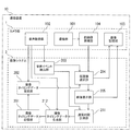
- FIG. 1 is an example of a functional block diagram for explaining a configuration of an imaging apparatus according to a first embodiment of the present invention. It is the figure which illustrated imaging timing data of a 1st embodiment of the present invention. It is an example of the flowchart for demonstrating operation
- FIG. 1 is an example of a functional block diagram for explaining the configuration of the imaging apparatus 10 according to the first embodiment.
- the imaging apparatus 10 of the first embodiment is a camera that captures still images.
- the configuration shown in FIG. 1 shows a camera unit 1 and an imaging system 2 incorporated in the imaging apparatus 10.
- the camera unit 1 mainly has a hardware configuration.
- the imaging system 2 includes a known microcomputer having data stored in a memory of the imaging device 10 (not shown) and a CPU (Central Processing Unit) and a memory (not shown) of the imaging device 10.
- the camera unit 1 includes an imaging unit 101, a voice acquisition unit 102 that acquires voice data (sound data) generated by speech and the like, an image storage unit 103 that stores captured image data, and the like.
- a temporary image storage unit 104 It should be noted that “utterance etc.” includes not only utterances but also sounds uttered from tools that make sounds such as dog whistle.
- the imaging unit 101 includes a lens and its control unit.
- the imaging unit 101 has both a function of capturing a still image according to a user's imaging instruction and a function of automatically capturing a still image in addition to the user's imaging instruction.
- the function of automatically and continuously capturing still images may be constantly operating, or may be started based on a user instruction.
- the voice acquisition unit 102 converts the analog input voice into digital data and outputs the result as voice data.
- the sound acquisition unit 102 has a configuration in which sound is input, analog-digital conversion is performed on the input sound, and then analysis is performed using Fourier transform or the like to generate sound data.
- HMM hidden Markov model
- the most likely phoneme sequence can be extracted from predetermined phoneme sequences.
- the extracted phoneme string (or a phonetic symbol string can be assumed) is used as voice information. Note that since the voice recognition processing by the HMM is a known technique, further detailed description is omitted.
- the audio data referred to in the first embodiment is a data group that is analyzed by using Fourier transform or the like after analog-digital conversion of the audio.
- the image storage unit 103 includes a memory that stores images as data, and a program that controls the operation of the memory.
- the image storage unit 103 stores the image captured by the imaging unit 101 in a non-temporary manner. Specifically, a still image captured by the imaging unit 101 in accordance with a user's imaging instruction, an image selected by the user from among still images stored in a temporary image storage unit 104 described later, and the like are temporarily stored in the image storage unit 103. Is stored as simple data.
- the image storage unit 103 may store the image data of the still image captured by the imaging unit 101 and the time when the still image is captured in association with each other.
- the temporary image storage unit 104 includes a memory that stores images as data, and a program that controls the operation of the memory.
- the temporary image storage unit 104 stores data in which image data of a still image automatically captured by the imaging unit 101 is associated with the time of imaging.
- the data stored in the temporary image storage unit 104 is preferably discarded after a certain time from the viewpoint of memory capacity. This fixed time is preferably set in consideration of a delay time stored in an imaging timing data storage unit 201 described later.
- image-capture time is measured by, for example, a clock built in the camera.
- imaged time may be the time itself (absolute time) measured by a clock built in the camera, or may be an elapsed time (relative time) starting from the camera activation or imaging start time.
- the still image automatically captured by the imaging unit 101 has a lower image quality (resolution / focus) than the still image captured by the user's imaging instruction, and the temporary image storage unit 104 Is preferably stored in the memory.
- the still image automatically captured by the image capturing unit 101 is stored in the temporary image storage unit 104 at a time before an audio event is detected by the audio event detection unit 203 described later. Preferably, only is stored and not stored after an audio event is detected.
- the imaging system 2 includes an imaging timing data storage unit 201, an imaging timing data designation unit 202, an audio event detection unit 203, a temporary image selection unit 204, and an image display unit 205.
- the imaging timing data storage unit 201 stores imaging timing data in which audio information and delay time information are associated with each other.
- FIG. 2 is a diagram illustrating imaging timing data.
- the imaging timing data shown in FIG. 2 includes delay time information that is information related to the delay time, voice information related to speech (for example, phoneme string or phonetic symbol string), and its ID number.
- voice information related to speech for example, phoneme string or phonetic symbol string
- ID number for example, phoneme string or phonetic symbol string
- a set of voice information related to voice and its ID number is used as voice recognition dictionary data.
- voice information for example, phonetic symbol string “return” obtained by uttering “return” is stored as voice recognition dictionary data of ID number 1, and the imaging timing data is This ID number 1 is configured to be associated with delay time information of “ ⁇ 2 seconds”. Further, as voice recognition dictionary data of ID number 2, voice information (for example, phonetic symbol string “return”) obtained by uttering “slightly return” is stored, and imaging timing data is stored in this ID number 2. -1 second "delay time information is associated with each other.
- the imaging timing data may include not only negative delay time information but also positive ones.
- voice information for example, phonetic symbol string “Chizu” obtained by uttering “cheese” is stored as voice recognition dictionary data of ID number 3, and imaging timing data is “+2 seconds” in this ID number 3.
- the delay time information may be associated with each other.
- Imaging timing data specifying unit 202 Based on the audio data output from the audio acquisition unit 102 and the audio information included in the imaging timing data (linked by the ID number), the plurality of imaging timing data stored in the imaging timing data storage unit 201 is selected. As a result of performing speech recognition processing on the speech data output from the speech acquisition unit 102, one imaging timing data including the most likely speech information is designated.
- the voice recognition process for selecting the most likely voice information from the voice data obtained from the output of the voice acquisition unit 102 may be performed using a known method such as likelihood comparison in the voice recognition process using the HMM, and will not be described. .
- the voice event detection unit 203 detects a voice event indicating any of the start of voice, the end of voice, the start of voice recognition processing, and the end of voice recognition processing from the voice data. Specifically, the audio event detection unit 203 receives the audio data output from the audio acquisition unit 102 and detects the audio event and the time when the audio event occurred.
- the start of speech or the like is an utterance start event
- the end of utterance or the like is an utterance end event
- the start of speech recognition processing is the speech recognition process start event
- the end of speech recognition processing is the speech recognition process end event. To do.
- These speech start event, speech end event, speech recognition process start event, and speech recognition process end event are combined into a speech event.
- the audio event detection unit 203 starts the utterance or the like when the energy of the audio data (audio signal) output from the audio acquisition unit 102 or the degree of change in energy exceeds the first threshold value for the first time. Detect. Further, it detects that the energy of the audio signal or the degree of energy change is below the second threshold as the end of the speech, and outputs the time.
- a speech recognition process start event is detected when a certain number of times that the first threshold is exceeded at the same time as an utterance start event, or after a certain time has elapsed from the utterance end event or after a certain time has elapsed from the utterance end event.
- the determined timing is used as a speech recognition process end event, and the time is output.
- the voice events detected by the voice event detection unit 203 include an utterance start event, an utterance end event, a voice recognition process start event, and a voice recognition process end event.
- the voice events include an utterance start event and an utterance end event. It is preferable to use either of these. This is because there is a higher possibility that the image desired by the user is presented when either the utterance start event or the utterance end event is used.
- the provisional image selection unit 204 is based on the sound event detected by the sound event detection unit 203 and the delay time of the image capturing timing data specified by the image capturing timing data specifying unit 202. Select the still image captured at the time. Specifically, the temporary image selection unit 204 captures imaging timing data specified by the imaging timing data specification unit 202 from the time of the audio event detected by the audio event detection unit 203 among the still images included in the temporary image storage unit 104. The still image picked up at the nearest time is selected with respect to the time that is back by the delay time of. However, it is not always necessary to select only a still image captured at the nearest time, and a still image captured at a time slightly before and after may be selected.
- the image display unit 205 displays a still image captured by the imaging unit 101.
- the image display unit 205 displays one or more still images selected by the temporary image selection unit 204 among the still images stored in the temporary image storage unit 104.
- some or all of the still images stored in the temporary image storage unit 104 may be displayed together.
- the image display unit 205 includes selection means for the user to select a displayed still image, such as a touch panel function, and is configured so that the user can select the displayed still image.
- the image data selected by the user is sent to the image storage unit 103 and stored as non-temporary data in the image storage unit 103.
- FIG. 3 is a flowchart for explaining the operation of the imaging apparatus 10 according to the first embodiment.
- the imaging apparatus 10 first, automatic continuous imaging of the imaging unit 101 is started based on a user's system activation instruction (step S501). An image captured by automatic continuous imaging is stored in the temporary image storage unit 104 (step S502). When the user pronounces from this state, the voice acquisition unit 102 acquires voice (step S503). The voice acquisition unit 102 analyzes the acquired voice, converts it into voice data, and outputs the voice data to the voice event detection unit 203 and the imaging timing data designation unit 202 (step S504).
- the audio event detection unit 203 analyzes the audio data output from the audio acquisition unit 102 and detects an audio event and its occurrence time. The detected audio event and its occurrence time are transmitted to the temporary image selection unit 204 (step S505).
- the imaging timing data specifying unit 202 performs speech recognition processing (HMM collation processing) on the audio information included in the imaging timing data stored in the imaging timing data storage unit 201 and the audio data output by the audio acquisition unit 102 ( Step S506).
- imaging timing data including audio information corresponding to the audio data is stored (step S506: Yes)
- the imaging timing data is designated, and the delay time information of the designated imaging timing data is set as a temporary image selection unit. It transmits to 204 (step S507). If imaging timing data including corresponding audio information is not stored (step S506: No), the process returns to the audio acquisition process (step S503).
- the provisional image selection unit 204 is based on the sound event detected by the sound event detection unit 203 and the delay time of the image capturing timing data specified by the image capturing timing data specifying unit 202.
- a still image captured at the time is selected (step S508). Specifically, from the still image stored in the temporary image selection unit 204, only the delay time of the imaging timing data specified by the imaging timing data specifying unit 202 from the time of occurrence of the audio event detected by the audio event detection unit 203.
- a still image captured at a time closest to the retroactive time (and several still images captured at the previous and subsequent times) is selected.
- the image display unit 205 displays the still image selected by the temporary image selection unit 204 (step S509).
- still images are continuously and automatically captured and stored. Then, a still image captured at a time before a voice event issued by the user by a predetermined delay time is displayed on the image display unit 205. Therefore, the user can obtain a still image at a desired time starting from the utterance timing by referring to the still image displayed on the image display unit 205. In other words, by adopting such a configuration, it is possible to obtain a still image at a time near the desired imaging timing, so that the user desires without missing the imaging timing and without enormous effort on the user. An image can be presented.
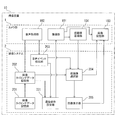
- FIG. 4 is an example of a functional block diagram for explaining the configuration of the imaging apparatus 10 according to the second embodiment.
- the imaging device 10 according to the second embodiment is an imaging device that can suitably set imaging timing data stored in the imaging timing data storage unit 201.
- the imaging device 10 according to the second embodiment further includes a delay time measurement unit 211 and an imaging timing data generation unit 212 in addition to the configuration of the imaging device 10 according to the first embodiment.
- the functional configuration is the same as that of the imaging device 10 according to the first embodiment, except that the processing of the imaging timing data storage unit 201 is partially different. Therefore, detailed description of the same part is omitted.
- the delay time measurement unit 211 generates a time when a still image specified by the user is captured from a plurality of still images displayed by the image display unit 205 and an audio event detected by the audio event detection unit 203. Measure the delay time, which is the time difference. Specifically, the time at which the still image specified by the user was captured from among the still images displayed by the image display unit 205 is an image at a time that is 3.5 seconds later with respect to the time at which the audio event occurred. If there is, the delay time measuring unit 211 measures the time of “ ⁇ 3.5 seconds”. The delay time measurement unit 211 outputs the measured delay time to the imaging timing data generation unit 212.
- the imaging timing data generation unit 212 generates imaging timing data in which the delay time measured by the delay time measurement unit 211 is associated with audio information based on audio data output from the audio acquisition unit 102. Specifically, when the user utters “go back” to the voice acquisition unit 102, voice information (for example, the phonetic symbol string “return”) corresponding to the utterance “go back” is captured from the voice acquisition unit 102. The delay time (for example, “ ⁇ 3.5 seconds”) measured by the delay time measuring unit 211 is output from the delay time measuring unit 211 to the imaging timing data generating unit 212. The imaging timing data generation unit 212 generates imaging timing data in which the phonetic symbol string “return” is associated with “ ⁇ 3.5 seconds”. The generated imaging timing data is output to the imaging timing data storage unit 201 and stored in the imaging timing data storage unit 201.
- the imaging timing data storage unit 201 in the second embodiment stores imaging timing data generated by the imaging timing data generation unit 212.
- the imaging timing data storage unit 201 may correct the delay time information of the imaging timing data having the same audio information to the delay time information of the imaging timing data generated by the imaging timing data generation unit 212.
- imaging timing data storage unit 201 imaging timing data in which a phonetic symbol string “return” that is already audio information is associated with “ ⁇ 2.0 seconds” that is delay time information is stored. It shall be remembered. Furthermore, the imaging timing data generated by the imaging timing data generation unit 212 is imaging timing data in which a phonetic symbol string “return” as audio information is associated with “ ⁇ 3.5 seconds” as delay time information. And In this case, the imaging timing data storage unit 201 corrects the content of the delay time information of the phonetic symbol string “return”, which is audio information, from “ ⁇ 2.0 seconds” to “ ⁇ 3.5 seconds”. By adopting the configuration of the second embodiment, it is possible to set the imaging timing data stored in the imaging timing data storage unit 201 to a suitable condition suitable for each user.
- FIG. 5 is an example of a functional block diagram for explaining the configuration of the imaging device 10 according to the third embodiment.
- the imaging device 10 according to the third embodiment is an imaging device that can suitably set imaging timing data stored in the imaging timing data storage unit 201.
- the imaging device 10 in the third embodiment further includes an imaging start event detection unit 221, a delay time measurement unit 222, and an imaging timing data generation unit 223 in addition to the configuration of the imaging device 10 in the first embodiment.
- the first embodiment except that the processing of the imaging timing data storage unit 201 is partially different with the addition of the imaging start event detection unit 221, the delay time measurement unit 222, and the imaging timing data generation unit 223. Therefore, the detailed description of the same part is omitted.
- the imaging start event detection unit 221 detects an imaging start event of the imaging unit 101 according to a user's imaging instruction and its time. As a specific example of the imaging start event, the shutter of the imaging unit 101 is manually pressed by the user.
- the delay time measurement unit 222 measures a delay time that is a difference in generation time between the imaging start event detected by the imaging start event detection unit 221 and the audio event detected by the audio event detection unit 203.
- a delay time that is a difference in generation time between the imaging start event detected by the imaging start event detection unit 221 and the audio event detected by the audio event detection unit 203.
- the imaging timing data generation unit 223 generates imaging timing data in which the delay time measured by the delay time measurement unit 222 is associated with the audio data output from the audio acquisition unit 102. Specifically, when the user utters “Cheese” to the voice acquisition unit 102, voice information corresponding to the utterance “Cheese” (for example, the phonetic symbol string “Chizu”) is captured from the voice acquisition unit 102. The data is output to the generation unit 223. Further, the delay time (for example, “2 seconds”) measured by the delay time measurement unit 222 is output from the delay time measurement unit 222 to the imaging timing data generation unit 223. The imaging timing data generation unit 223 generates imaging timing data in which the phonetic symbol string “Chizu” is associated with “+2 seconds”. The generated imaging timing data is stored in the imaging timing data storage unit 201.
- the imaging timing data storage unit 201 stores imaging timing data generated by the imaging timing data generation unit 223.
- the imaging timing data storage unit 201 may correct the delay time information of the imaging timing data having the same audio information to the delay time information of the imaging timing data generated by the imaging timing data generation unit 223.
- the imaging device 10 according to the fourth embodiment further includes an imaging operation setting unit 231 in addition to the configuration of the imaging device 10 according to any one of the first to third embodiments.
- the imaging device 10 in the first embodiment further includes an imaging operation setting unit 231 will be described.
- symbol is provided to the same part as the imaging device 10 in 1st Embodiment, and the detailed description is abbreviate
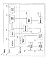
- FIG. 6 is an example of a functional block diagram for explaining the configuration of the imaging device 10 according to the fourth embodiment.
- the imaging operation setting unit 231 sets the imaging timing of the imaging unit 101 based on the audio event detected by the audio event detection unit 203 and the delay time of the imaging timing data specified by the imaging timing data specifying unit 202. This will be specifically described below.
- voice information for example, phonetic symbol string “Chizu” obtained by the user uttering “cheese” and delay time information (for example, “+2 seconds”) corresponding thereto are stored. Assume that associated imaging timing data is stored.
- the audio acquisition unit 102 outputs audio data corresponding to “cheese” to the audio event detection unit 203 and the imaging timing data designation unit 202.
- the audio event detection unit 203 detects the audio event and its time using the audio data output from the audio acquisition unit 102.
- the time of the detected audio event is output to the imaging operation setting unit 231.
- the imaging timing data specifying unit 202 performs voice recognition processing based on the audio data output from the audio acquisition unit 102 and the audio information included in the imaging timing data, and a plurality of imaging timings stored in the imaging timing data storage unit 201.
- the imaging timing data having the most likely audio information is designated from the data, and the delay time included in the imaging timing data is output to the imaging operation setting unit 231. In this specific example, a delay time of “+2 seconds” is output to the imaging operation setting unit 231.
- the imaging operation setting unit 231 gives a command to the imaging unit 101 so that imaging is performed at a time when 2 seconds have elapsed from the time of occurrence of the audio event. At this time, a command may be given to the imaging unit 101 so as to capture images at times before and after the delay time elapses from the occurrence time of the audio event.
- the imaging operation setting unit 231 sets the imaging timing, the imaging timing is set when the delay time of the imaging timing data specified by the imaging timing data specifying unit 202 is positive, that is, at a time after the audio event. It will be.
- Image data captured by the image capturing unit 101 based on a command from the image capturing operation setting unit 231 is stored in the image storage unit 103.
- the image data captured by the imaging unit 101 based on the command from the imaging operation setting unit 231 is highly likely to be an image desired by the user, the image data captured by the imaging unit 101 based on the command from the imaging operation setting unit 231 is captured. It is preferable that the image data has higher image quality (resolution / focus) than the image data automatically and continuously captured by the unit 101.
- FIG. 7 is an example of a functional block diagram for explaining the configuration of the imaging device 10 according to the fifth embodiment.
- the imaging device 10 according to the fifth embodiment further includes a delay time correction unit 241 in addition to the configuration of the imaging device 10 according to the fourth embodiment. Except that the processing of the image storage unit 103 is partly different due to the addition of the delay time correcting unit 241, the functional configuration is the same as that of the imaging device 10 in the fourth embodiment. Omitted.
- Image storage unit 103 In the image storage unit 103 according to the fifth embodiment, the imaging operation setting unit 231 sets the imaging timing, and the image captured by the imaging unit 101 is stored as image data. Then, it is possible to detect whether the captured image is accumulated or discarded. The image storage unit 103 notifies the delay time correction unit 241 of an image discard notification when the image data is discarded without being accumulated.
- the delay time correcting unit 241 includes the delay time included in the imaging timing data specified by the imaging timing data specifying unit 202. Correct the information. Specifically, when the delay time correction unit 241 receives the image discard notification output from the image storage unit 103, the imaging timing data specifying unit 202 among the imaging timing data stored in the imaging timing data storage unit 201. The delay time of the designated imaging timing data is corrected.
- the imaging timing set by the imaging operation setting unit 231 can be set to a suitable timing suitable for each user.
- the number and frequency at which image data is discarded or accumulated may be recorded for each imaging timing data. Then, when the number or frequency of discarding image data for the set delay time is lower than the threshold, the delay time can be prevented from being corrected. In this way, when the image data happens to be discarded due to another cause different from the delay time, it is possible to prevent the delay time set appropriately from being changed.
- the extension of the delay time of the fifth embodiment described above can be realized, for example, by increasing the delay time before correction by a fixed ratio and adding a certain time to the delay time before correction.
- the above-described fixed ratio and fixed time can be changed according to the number and frequency of image data discarded or stored in the past. The change may be performed so that a certain ratio or certain time is set larger as the number of times the image data is discarded increases.
- FIG. 8 is an example of a functional block diagram for explaining the configuration of the imaging apparatus 10 according to the sixth embodiment.
- the imaging device 10 according to the sixth embodiment further includes an image analysis unit 251 in addition to the configuration of the imaging device 10 according to the fourth embodiment or the fifth embodiment.
- the image analysis unit 251 is added to the imaging device 10 according to the fourth embodiment.
- the details of the same unit are detailed. Description is omitted.
- the image analysis unit 251 extracts morphological change information regarding the morphological change of the imaging target from the image captured by the imaging unit 101.
- the form change refers to a change in the appearance of the imaging target, and corresponds to a change in the expression of a person or a change in the posture of an animal. Since the detection of the shape change is a well-known technique in the field of the imaging device or the like, further explanation is omitted. For example, when the image analysis unit 251 detects that the person is smiling, the image analysis unit 251 notifies the imaging operation setting unit 231 of the detection result.
- Imaging operation setting unit 231 The imaging operation setting unit 231 notifies the imaging unit 101 of an imaging instruction when notified from the image analysis unit 251 that the person has smiled.
- This imaging instruction corresponds to an instruction to start imaging, and the imaging unit 101 starts imaging.
- the imaging operation setting unit 231 allows the person to smile or the animal to look at the camera or perform a trick while the set delay time elapses. Can be detected. Therefore, even when the delay time is automatically set, the imaging device 10 can start imaging at an appropriate timing without missing a photo opportunity before the delay time elapses.
- FIG. 9 is an example of a functional block diagram for explaining the configuration of the information processing apparatus 100 according to the seventh embodiment.
- the seventh embodiment relates to an information processing apparatus 100 that is incorporated in an imaging apparatus or the like.
- the embodiment focuses on the information processing apparatus 100 that performs processing for generating imaging timing data in the imaging apparatus 10 described in the third embodiment. It is a form.
- the same reference numerals are given to the same parts as those of the imaging device 10 shown in FIG. 5 in the third embodiment, and the detailed description thereof is omitted.
- an audio acquisition unit 102 that outputs a result obtained by converting analog input audio into a digital signal and outputs the result as audio data
- an imaging unit 101 that has a function of imaging a still image according to a user's imaging instruction.
- the information processing apparatus 100 incorporated in the imaging apparatus 10.
- the information processing apparatus 100 includes an audio event detection unit 203 that detects an audio event indicating the start or end of audio from audio data output from the audio acquisition unit 102, and imaging of the imaging unit 101 according to a user's imaging instruction.
- the imaging timing for generating imaging timing data that associates the delay time measuring unit 222, the delay time information related to the delay time measured by the delay time measuring unit 222, and the audio information based on the audio data output from the audio acquisition unit 102
- Data generation unit 223 and imaging timing data generation unit An imaging timing data storage unit 201 the image capturing timing data is stored which is generated by 23, made comprises a.
- Imaging device 101 Imaging part 102 Audio
Landscapes
- Engineering & Computer Science (AREA)
- Multimedia (AREA)
- Signal Processing (AREA)
- Studio Devices (AREA)
- Details Of Cameras Including Film Mechanisms (AREA)
- Television Signal Processing For Recording (AREA)
Abstract
Description
上記したカメラは、例えば、特許文献1に記載されている。特許文献1記載の発明によれば、カメラの操作者は、被写体の動作に合わせた自然な写真を撮影することが可能になる。また、特許文献1には、発話のタイミングからシャッターが押下されるまでの時間(以下、遅延時間と記す)を任意に設定することが記載されている。
撮像タイミングを逃さない方法として、ユーザが指示したタイミングにおける撮像以外にも静止画を自動で撮像しておき、自動撮像した画像をメモリに記憶させておく方法が考えられる。しかし、この方法の場合、ユーザは自動撮像された大量の画像の中から自分の望む画像を探し出す必要があり、ユーザに多大な手間を強いることとなる。
本発明は、このような点に鑑みてなされたものであり、撮像タイミングを逃すことなく、且つ、ユーザに多大な手間を強いることなくユーザが望む画像を提示することが可能な撮像装置及び情報処理装置を提供することにある。
前記撮像部が撮像する静止画を表示する画像表示部(例えば図1に示す画像表示部205)と、前記撮像部が撮像する静止画を記憶する画像記憶部(例えば図1に示す画像記憶部103)と、をさらに備えていてよい。
前記画像表示部は、前記仮画像蓄積部に記憶される静止画のうち、前記仮画像選択部が選択した静止画と、前記仮画像選択部が選択した静止画が撮像された時刻の前後の時刻に撮像された静止画と、を表示するようになっていてよい。
前記画像記憶部は、前記画像表示部が表示する静止画の中からユーザが指定した静止画の画像データを記憶するようになっていてよい。
前記撮像動作設定部は、前記撮像タイミングを前記音声イベントより後の時刻にタイミングを設定するようになっていてよい。
前記撮像動作設定部が設定する前記撮像タイミングにしたがって前記撮像部が撮像したデータが前記画像記憶部に保存されなかった場合、前記撮像タイミングデータ指定部によって指定された前記撮像タイミングデータに含まれる遅延時間情報を修正する遅延時間修正部(例えば図7に示す遅延時間修正部241)を備えていてよい。
(第1実施形態)
図1は、第1実施形態の撮像装置10の構成を説明するための機能ブロック図の一例である。なお、第1実施形態の撮像装置10は、静止画像を撮像するカメラであるものとする。
図1に示した構成は、撮像装置10に組み込まれたカメラ部1と、撮像システム2とを示している。カメラ部1は、主にハードウェア構成である。また、撮像システム2は、図示しない撮像装置10のメモリに保存されているデータと、撮像装置10の図示しないCPU(Central Processing Unit)やメモリを有する公知のマイクロコンピュータによって構成されている。
図1に示したように、カメラ部1は、撮像部101、発話等によって生じる音声のデータ(音声データ)を取得する音声取得部102、撮像された画像のデータを記憶する画像記憶部103と、仮画像蓄積部104と、を備えている。なお、「発話等」には発話の他、犬笛など音を発する道具から発せられる音声を含むものとする。
撮像部101はレンズやその制御部によって構成される。撮像部101は、ユーザの撮像指示により静止画を撮像する機能と、ユーザの撮像指示以外に自動で連続して静止画を撮像する機能と、の両方の機能を備えている。自動で連続して静止画を撮像する機能は、常に動作していてもよく、また、ユーザの指示に基づいて動作が開始されてもよい。
音声取得部102は、アナログ入力された音声をデジタルに変換して解析した結果を音声データとして出力する。具体的には、音声取得部102は、音声を入力し、入力された音声に対してアナログデジタル変換を行った後に、フーリエ変換等を使って解析し、音声データにする構成を備える。この音声データに対して隠れマルコフモデル(以下「HMM」と呼ぶ)を利用して音声認識処理を行うことにより、予め定められた音素列の中で最も尤もらしい音素列を抽出することができる。第1実施形態では、一例として、この抽出された音素列(あるいは発音記号列の場合も想定できる)を音声情報としている。なお、HMMによる音声認識処理は、公知の技術であるから、これ以上の詳細な説明を省くものとする。第1実施形態でいう音声データとは、音声をアナログデジタル変換した後に、フーリエ変換等を使って解析したデータ群である。
画像記憶部103は、画像をデータとして蓄積するメモリと、このメモリの動作を制御するプログラムとから構成される。
画像記憶部103は、撮像部101が撮像した画像を非一時的に保存する。具体的には、ユーザの撮像指示により撮像部101が撮像した静止画や後述の仮画像蓄積部104に記憶された静止画の中からユーザが選択した画像などが画像記憶部103に非一時的なデータとして記憶される。画像記憶部103には、撮像部101が撮像した静止画の画像データとその静止画が撮像された時刻とが対応付けて記憶されるようになっていてもよい。
仮画像蓄積部104は、画像をデータとして蓄積するメモリと、このメモリの動作を制御するプログラムとから構成される。
仮画像蓄積部104には、撮像部101が自動で撮像した静止画の画像データと撮像した時刻とが対応づけられたデータが記憶される。仮画像蓄積部104に記憶されるデータはメモリ容量の観点から、一定時間後に破棄されることが好ましい。この一定時間は、後述の撮像タイミングデータ記憶部201に記憶される遅延時間を考慮して設定されることが好ましい。
なお、この「撮像した時刻」とはカメラが内蔵する時計により計測された時刻そのもの(絶対時刻)でもよいし、カメラ起動時や撮像開始時点を起点とした経過時間(相対時間)でもよい。
また同様に、メモリ容量や処理量の観点から、撮像部101が自動で撮像した静止画は、ユーザの撮像指示により撮像した静止画よりも画質(解像度・フォーカス)を落として仮画像蓄積部104に記憶されることが好ましい。
撮像システム2は、撮像タイミングデータ記憶部201と、撮像タイミングデータ指定部202と、音声イベント検出部203と、仮画像選択部204と、画像表示部205と、から構成される。
撮像タイミングデータ記憶部201には、音声情報と遅延時間情報とが関連付けられた撮像タイミングデータが記憶されている。図2は、撮像タイミングデータを例示した図である。図2に示した撮像タイミングデータは、遅延時間に関する情報である遅延時間情報と、音声に関する音声情報(たとえば音素列や発音記号列)とそのID番号で構成される。なお、第1実施形態では、音声に関する音声情報とそのID番号の組を音声認識辞書データとする。
また、ID番号2の音声認識辞書データとして、「ちょっと戻って」を発話して得られる音声情報(たとえば発音記号列「ちょっともどって」)が格納され、撮像タイミングデータはこのID番号2に「-1秒」の遅延時間情報を対応付けて構成されている。
音声取得部102が出力する音声データと、撮像タイミングデータに含まれる(ID番号で紐付けられた)音声情報とに基づいて、撮像タイミングデータ記憶部201が記憶する複数の撮像タイミングデータの中から、音声取得部102が出力する音声データを音声認識処理した結果最も尤もらしい音声情報が含まれる一つの撮像タイミングデータを指定する。
音声取得部102の出力から得られる音声データから最も尤もらしい音声情報を選出する音声認識処理についてはHMMを利用した音声認識処理における尤度比較など公知の方法を用いればよいので、説明を省略する。
音声イベント検出部203は、音声データから音声の開始、音声の終了、音声認識処理の開始、音声認識処理の終了の何れかを示す音声イベントを検出する。具体的には、音声イベント検出部203は、音声取得部102が出力する音声データを受け取り、音声イベントと音声イベントが発生した時刻とを検出する。本明細書では、発話等の開始を発話開始イベントとし、発話等の終了を発話終了イベントとし、音声認識処理の開始を音声認識処理開始イベントとし、音声認識処理の終了を音声認識処理終了イベントとする。そして、これら発話開始イベントと発話終了イベントと音声認識処理開始イベントと音声認識処理終了イベントとを合わせて音声イベントとする。
なお、音声イベント検出部203が検出する音声イベントとして、発話開始イベントと発話終了イベントと音声認識処理開始イベントと音声認識処理終了イベントが挙げられるが、音声イベントとしては、発話開始イベントと発話終了イベントのどちらかを使用することが好ましい。これは、発話開始イベントと発話終了イベントのどちらかを使用した場合の方がよりユーザが望む画像を提示する可能性が高くなるためである。
仮画像選択部204は、音声イベント検出部203が検出する音声イベントと撮像タイミングデータ指定部202が指定する撮像タイミングデータの遅延時間とに基づき、仮画像蓄積部104の中から音声イベントより前の時刻に撮像された静止画を選択する。
具体的には、仮画像選択部204は、仮画像蓄積部104に含まれる静止画のうち、音声イベント検出部203が検出する音声イベントの時刻から撮像タイミングデータ指定部202が指定する撮像タイミングデータの遅延時間分だけ遡った時刻に対し、最も近い時刻に撮像された静止画を選択する。ただし、必ずしも最も近い時刻に撮像された静止画のみを選択する必要はなく、多少時刻が前後した時刻に撮像された静止画も含めて選択しても良い。
画像表示部205は撮像部101が撮像した静止画を表示する。画像表示部205には、仮画像蓄積部104に記憶される静止画のうち、仮画像選択部204が選択した1枚あるいは複数枚の静止画が表示される。
仮画像選択部204が選択した画像の他、仮画像蓄積部104に保存された静止画の一部又は全部を合わせて表示させてもよい。表示の際には、撮像された時刻の昇順または降順に表示させることが好ましい。
画像表示部205は、例えばタッチパネル機能など、表示された静止画をユーザが選択するための選択手段を備えており、表示された静止画をユーザが選択可能に構成されている。そして、画像表示部205に表示された静止画のうち、ユーザに選択された画像のデータは、画像記憶部103に送られ非一時的なデータとして画像記憶部103に記憶される。
図3は、第1実施形態の撮像装置10の動作を説明するためのフローチャートである。
撮像装置10では、先ず、ユーザのシステム起動の指示に基づき、撮像部101の自動連続撮像が開始される(ステップS501)。
自動連続撮像により撮像された画像は仮画像蓄積部104に記憶される(ステップS502)。
この状態からユーザが発音すると、音声取得部102によって音声が取得される(ステップS503)。
音声取得部102は取得した音声を解析し、音声データに変換し、音声データを音声イベント検出部203と撮像タイミングデータ指定部202に出力する(ステップS504)。
撮像タイミングデータ指定部202は、撮像タイミングデータ記憶部201に記憶されている撮像タイミングデータに含まれる音声情報と音声取得部102が出力する音声データとを音声認識処理(HMMによる照合処理)する(ステップS506)。
なお、対応する音声情報を含む撮像タイミングデータが記憶されていない場合は(ステップS506:No)音声取得処理(ステップS503)に戻る。
画像表示部205は仮画像選択部204が選択した静止画を表示する(ステップS509)。
次に、本発明の第2実施形態を説明する。
図4は、第2実施形態における撮像装置10の構成を説明するための機能ブロック図の一例である。
第2実施形態における撮像装置10は、撮像タイミングデータ記憶部201に記憶される撮像タイミングデータを好適に設定することが可能な撮像装置である。第2実施形態における撮像装置10は、第1実施形態における撮像装置10の構成に加え、遅延時間計測部211と、撮像タイミングデータ生成部212と、をさらに備える。遅延時間計測部211及び撮像タイミングデータ生成部212が追加されたことに伴い、撮像タイミングデータ記憶部201の処理が一部異なること以外は、第1実施形態における撮像装置10と同様の機能構成を有するため、同一部の詳細な説明は省略する。
遅延時間計測部211は、画像表示部205が表示する複数枚の静止画の中からユーザが指定した静止画が撮像された時刻と、音声イベント検出部203によって検出された音声イベントと、の発生時間差である遅延時間を計測する。
具体的には、画像表示部205が表示する静止画の中からユーザが指定した静止画が撮像された時刻が、音声イベントが発生した時刻を基準に、3.5秒遡った時刻の画像であった場合、遅延時間計測部211はその「-3.5秒」という時刻を計測する。遅延時間計測部211は、計測した遅延時間を撮像タイミングデータ生成部212に出力する。
撮像タイミングデータ生成部212は、遅延時間計測部211によって計測された遅延時間と、音声取得部102が出力する音声データに基づく音声情報とを関連付けた撮像タイミングデータを生成する。
具体的には、ユーザが音声取得部102に対し「戻って」と発話した場合、「戻って」という発話に対応する音声情報(たとえば発音記号列「もどって」)が音声取得部102から撮像タイミングデータ生成部212に出力され、さらに、遅延時間計測部211が計測した遅延時間(例えば、「-3.5秒」)が遅延時間計測部211から撮像タイミングデータ生成部212に出力される。
撮像タイミングデータ生成部212は、発音記号列「もどって」と「-3.5秒」とを関連付けた撮像タイミングデータを生成する。生成された撮像タイミングデータは撮像タイミングデータ記憶部201に出力され、撮像タイミングデータ記憶部201に記憶される。
この第2実施形態における撮像タイミングデータ記憶部201は、撮像タイミングデータ生成部212が生成した撮像タイミングデータを記憶する。撮像タイミングデータ記憶部201内に、撮像タイミングデータ生成部212が生成した撮像タイミングデータが保有する音声情報と同様の音声情報を保有する撮像タイミングデータが既に記憶されている場合、撮像タイミングデータ記憶部201は、その同様の音声情報を保有する撮像タイミングデータの遅延時間情報を撮像タイミングデータ生成部212が生成した撮像タイミングデータの遅延時間情報に修正してもよい。
この場合、撮像タイミングデータ記憶部201は、音声情報である発音記号列「もどって」の遅延時間情報を「-2.0秒」から「-3.5秒」にその内容を修正する。
第2実施形態の構成を採用することで、撮像タイミングデータ記憶部201に記憶される撮像タイミングデータを各ユーザに適した好適な条件に設定することが可能となる。
次に、本発明の第3実施形態を説明する。
図5は、第3実施形態における撮像装置10の構成を説明するための機能ブロック図の一例である。
第3実施形態における撮像装置10は、撮像タイミングデータ記憶部201に記憶される撮像タイミングデータを好適に設定することが可能な撮像装置である。第3実施形態における撮像装置10は、第1実施形態における撮像装置10の構成に加え、撮像開始イベント検出部221と、遅延時間計測部222と、撮像タイミングデータ生成部223と、をさらに備える。撮像開始イベント検出部221と、遅延時間計測部222と、撮像タイミングデータ生成部223とが追加されたことに伴い、撮像タイミングデータ記憶部201の処理が一部異なること以外は、第1実施形態における撮像装置10と同様の機能構成を有するため、同一部の詳細な説明は省略する。
撮像開始イベント検出部221はユーザの撮像指示による撮像部101の撮像開始イベントとその時刻を検出する。撮像開始イベントの具体例としては、撮像部101のシャッターがユーザにより手動で押下されることなどが該当する。
遅延時間計測部222は、撮像開始イベント検出部221によって検出された撮像開始イベントと、音声イベント検出部203によって検出された音声イベントと、の発生時間差である遅延時間を計測する。
具体例としては、ユーザが「チーズ」と発話してから2秒後に、撮像部101のシャッターがユーザにより手動で押下された場合、音声イベントと撮像開始イベントとの発生時間差である「2秒」が遅延時間計測部222によって計測される。
撮像タイミングデータ生成部223は、遅延時間計測部222によって計測された遅延時間と、音声取得部102が出力する音声データとを関連付けた撮像タイミングデータを生成する。
具体的には、ユーザが音声取得部102に対し「チーズ」と発話した場合、「チーズ」という発話に対応する音声情報(たとえば発音記号列「ちいず」)が音声取得部102から撮像タイミングデータ生成部223に出力される。さらに、遅延時間計測部222が計測した遅延時間(例えば、「2秒」)が遅延時間計測部222から撮像タイミングデータ生成部223に出力される。
撮像タイミングデータ生成部223は、発音記号列「ちいず」と「+2秒」とを関連付けた撮像タイミングデータを生成する。生成された撮像タイミングデータは撮像タイミングデータ記憶部201に記憶される。
撮像タイミングデータ記憶部201は撮像タイミングデータ生成部223が生成した撮像タイミングデータを記憶する。撮像タイミングデータ記憶部201内に、撮像タイミングデータ生成部223が生成した撮像タイミングデータが保有する音声情報と同様の音声情報を保有する撮像タイミングデータが既に記憶されている場合、撮像タイミングデータ記憶部201はその同様の音声情報を保有する撮像タイミングデータの遅延時間情報を撮像タイミングデータ生成部223が生成した撮像タイミングデータの遅延時間情報に修正してもよい。
第3実施形態における撮像装置10の構成を採用することで、撮像タイミングデータ記憶部201に記憶される撮像タイミングデータを各ユーザに適した好適な条件に設定することが可能となる。
次に、本発明の第4実施形態を説明する。
第4実施形態における撮像装置10は、第1~第3実施形態の何れかの実施形態における撮像装置10の構成に加え、撮像動作設定部231をさらに備える。
ここでは、第1実施形態における撮像装置10において、さらに撮像動作設定部231を備える場合について説明する。なお、第1実施形態における撮像装置10と同一部には同一符号を付与し、その詳細な説明は省略する。
図6は、第4実施形態における撮像装置10の構成を説明するための機能ブロック図の一例である。
撮像動作設定部231は、音声イベント検出部203が検出する音声イベントと、撮像タイミングデータ指定部202により指定された撮像タイミングデータの遅延時間とに基づき、撮像部101の撮像タイミングを設定する。
以下、具体的に説明する。
ここで、撮像タイミングデータ記憶部201に、ユーザが「チーズ」を発話して得られる音声情報(たとえば発音記号列「ちいず」)と、それに対応する遅延時間情報(例えば「+2秒」)が対応付けられた撮像タイミングデータが記憶されているとする。
そして、ユーザが音声取得部102に対して「チーズ」を発話すると、音声取得部102は「チーズ」に対応する音声データを音声イベント検出部203と、撮像タイミングデータ指定部202と、に出力する。
撮像タイミングデータ指定部202は、音声取得部102が出力する音声データと、撮像タイミングデータに含まれる音声情報とに基づいて音声認識処理を行い、撮像タイミングデータ記憶部201が記憶する複数の撮像タイミングデータの中から最も尤もらしい音声情報を持つ撮像タイミングデータを指定し、その撮像タイミングデータに含まれる遅延時間を撮像動作設定部231に出力する。本具体例では、「+2秒」という遅延時間が撮像動作設定部231に出力される。
撮像動作設定部231が撮像タイミングを設定する場合は、撮像タイミングデータ指定部202により指定された撮像タイミングデータの遅延時間が正の場合、つまり、音声イベントより後の時刻に撮像タイミングが設定されることとなる。撮像動作設定部231の指令に基づき撮像部101が撮像した画像データは画像記憶部103に記憶される。撮像動作設定部231の指令に基づき撮像部101が撮像した画像データはユーザの望む画像である可能性が高いので、撮像動作設定部231の指令に基づき撮像部101が撮像した画像データは、撮像部101が自動連続撮像した画像データよりも高画質(解像度・フォーカス)のデータとすることが好ましい。
第4実施形態の構成を採用することで、音声イベントに応じて、好適なタイミングで自動的に撮像部101による撮像を行うことができる。
次に、本発明の第5実施形態を説明する。
図7は、第5実施形態における撮像装置10の構成を説明するための機能ブロック図の一例である。
第5実施形態における撮像装置10は、第4実施形態における撮像装置10の構成に加え、遅延時間修正部241をさらに備える。遅延時間修正部241を追加したことに伴い、画像記憶部103の処理が一部異なること以外は、第4実施形態における撮像装置10と同様の機能構成を有するため、同一部の詳細な説明は省略する。
この第5実施形態における画像記憶部103は、撮像動作設定部231が撮像タイミングを設定し、撮像部101が撮像した画像を、画像データとして蓄積する。そして、撮像された画像が蓄積されたか、あるいは破棄されたかを検出することができる。
画像記憶部103は、画像データが蓄積されずに破棄された場合、画像破棄通知を遅延時間修正部241に通知する。
遅延時間修正部241は、撮像動作設定部231が設定する撮像タイミングにより撮像部101が撮像したデータが蓄積されなかった場合、撮像タイミングデータ指定部202によって指定された撮像タイミングデータに含まれる遅延時間情報を修正する。詳細には、遅延時間修正部241は、画像記憶部103から出力される画像破棄通知を受けると、撮像タイミングデータ記憶部201に記憶されている撮像タイミングデータのうち、撮像タイミングデータ指定部202が指定する撮像タイミングデータの遅延時間を修正する。
そのため、撮像動作設定部231が設定する撮像タイミングを各ユーザに適した好適なタイミングに設定することができる。
次に、本発明の第6実施形態を説明する。
図8は、第6実施形態における撮像装置10の構成を説明するための機能ブロック図の一例である。
第6実施形態における撮像装置10は、第4実施形態又は第5実施形態における撮像装置10の構成に加え、さらに画像解析部251を備える。ここでは、第4実施形態における撮像装置10において、画像解析部251を追加した場合について説明する。
なお、画像解析部251を追加したことに伴い、撮像動作設定部231の処理が一部異なること以外は、第4実施形態における撮像装置10と同様の機能構成を有するため、同一部の詳細な説明は省略する。
画像解析部251は、撮像部101によって撮像された画像から、撮像対象の形態変化に関する形態変化情報を抽出する。形態変化とは、撮像対象の外観が変化することをいい、人物の表情の変化や動物の姿勢の変化が該当する。形態変化の検出は、撮像装置等の分野において公知の技術であるから、これ以上の説明を省く。
画像解析部251は、例えば、人物が笑顔になったことを検出すると、検出結果を撮像動作設定部231に通知する。
撮像動作設定部231は、画像解析部251から、人物が笑顔になったことが通知されると、撮像部101に撮像指示を通知する。この撮像指示は、撮像の開始の指示に該当し、撮像部101は撮像を開始する。
このような構成によれば、撮像動作設定部231は、設定した遅延時間が経過する間にも、人物が笑顔になったことや動物がカメラの方を見たり、芸をしたりすることを検出することができる。このため、撮像装置10は、遅延時間を自動的に設定した場合であっても、遅延時間経過以前のシャッターチャンスを逃すことなく、適切なタイミングで撮像を開始することができる。
次に、本発明の第7実施形態を説明する。
図9は、第7実施形態における情報処理装置100の構成を説明するための機能ブロック図の一例である。
第7実施形態は、撮像装置等に組み込まれる情報処理装置100に関するものであり、第3実施形態に記載された撮像装置10において撮像タイミングデータを生成する処理を行う情報処理装置100に着目した実施形態である。図9において、第3実施形態における図5に示す撮像装置10と同一部には同一符号を付与し、その詳細な説明は省略する。
音声イベント検出部203、遅延時間計測部222、撮像タイミングデータ生成部223、撮像タイミングデータ記憶部201に関する説明は第3実施形態に記載の説明と同様なので省略する。
第7実施形態の構成を採用することで、撮像タイミングデータ記憶部201に記憶される撮像タイミングデータを各ユーザに適した好適な条件に設定することが可能となる。
101 撮像部
102 音声取得部
103 画像記憶部
104 仮画像蓄積部
201 撮像タイミングデータ記憶部
202 撮像タイミングデータ指定部
203 音声イベント検出部
204 仮画像選択部
205 画像表示部
211 遅延時間計測部
212 撮像タイミングデータ生成部
221 撮像開始イベント検出部
222 遅延時間計測部
223 撮像タイミングデータ生成部
231 撮像動作設定部
241 遅延時間修正部
251 画像解析部
Claims (11)
- 取得した音声を音声データとして出力する音声取得部と、
ユーザの撮像指示により静止画を撮像する機能と、ユーザの撮像指示以外に自動で静止画を撮像する機能と、を有する撮像部と、を備える撮像装置であって、
前記撮像部が自動で連続して撮像した静止画の画像データが記憶される仮画像蓄積部と、
音声情報と遅延時間情報とが関連付けられた撮像タイミングデータが記憶された撮像タイミングデータ記憶部と、
前記音声取得部が出力する前記音声データに基づいて、前記撮像タイミングデータ記憶部に記憶された複数の撮像タイミングデータの中から、前記音声取得部が出力する前記音声データに対応する音声情報が含まれる撮像タイミングデータを指定する撮像タイミングデータ指定部と、
前記音声データから音声の開始、音声の終了、音声認識処理の開始、音声認識処理の終了の何れかを示す音声イベントを検出する音声イベント検出部と、
前記音声イベントと前記撮像タイミングデータ指定部により指定された前記撮像タイミングデータの遅延時間に基づき、前記仮画像蓄積部の中から前記音声イベントより前の時刻に撮像された静止画を選択する仮画像選択部と、
を備えることを特徴とする撮像装置。 - 前記音声イベント検出部は前記音声データから音声の開始または終了を示す音声イベントを検出することを特徴とする請求項1に記載の撮像装置。
- 前記撮像部が撮像する静止画を表示する画像表示部と、
前記撮像部が撮像する静止画を記憶する画像記憶部と、
をさらに備えることを特徴とする請求項1又は請求項2に記載の撮像装置。 - 前記画像表示部は、前記仮画像蓄積部に記憶される静止画のうち、前記仮画像選択部が選択した静止画と、前記仮画像選択部が選択した静止画が撮像された時刻の前後の時刻に撮像された静止画と、を表示することを特徴とする請求項3に記載の撮像装置。
- 前記画像記憶部は、前記画像表示部が表示する静止画の中からユーザが指定した静止画の画像データを記憶することを特徴とする請求項3又は請求項4に記載の撮像装置。
- 前記画像表示部が表示する静止画の中からユーザが指定した静止画が撮像された時刻と、前記音声イベント検出部によって検出された音声イベントと、の発生時間差である遅延時間を計測する遅延時間計測部と、
前記遅延時間計測部によって計測された遅延時間に関する遅延時間情報と、前記音声取得部が出力する前記音声データに基づく音声情報とを関連付けた撮像タイミングデータを生成する撮像タイミングデータ生成部と、を備え、
前記撮像タイミングデータ記憶部は、前記撮像タイミングデータ生成部が生成する前記撮像タイミングデータが記憶されることを特徴とする請求項1から請求項5の何れか1項に記載の撮像装置。 - 前記撮像部のユーザの撮像指示による撮像の撮像開始イベントを検出する撮像開始イベント検出部と、
前記撮像開始イベント検出部によって検出された撮像開始イベントと、前記音声イベント検出部によって検出された音声イベントと、の発生時間差である遅延時間を計測する遅延時間計測部と、
前記遅延時間計測部によって計測された遅延時間に関する遅延時間情報と、前記音声取得部が出力する前記音声データに基づく音声情報とを関連付けた撮像タイミングデータを生成する撮像タイミングデータ生成部と、を備え、
前記撮像タイミングデータ記憶部は、前記撮像タイミングデータ生成部が生成する前記撮像タイミングデータが記憶されることを特徴とする請求項1から請求項5の何れか1項に記載の撮像装置。 - 前記音声イベント検出部が検出する前記音声イベントと、前記撮像タイミングデータ指定部により指定された前記撮像タイミングデータの遅延時間とに基づき、前記撮像部の撮像タイミングを設定する撮像動作設定部、を備えることを特徴とする請求項1から請求項7の何れか1項に記載の撮像装置。
- 前記撮像動作設定部は、前記撮像タイミングを前記音声イベントより後の時刻にタイミングを設定することを特徴とする請求項8に記載の撮像装置。
- 前記撮像動作設定部が設定する前記撮像タイミングにしたがって前記撮像部が撮像したデータが前記画像記憶部に保存されなかった場合、前記撮像タイミングデータ指定部によって指定された前記撮像タイミングデータに含まれる遅延時間情報を修正する遅延時間修正部を備えることを特徴とする請求項8又は請求項9に記載の撮像装置。
- 取得した音声を音声データとして出力する音声取得部と、ユーザの撮像指示により静止画を撮像する機能を有する撮像部と、を備える撮像装置に組込まれる情報処理装置であって、
前記音声取得部から出力される音声データから音声の開始または終了を示す音声イベントを検出する音声イベント検出部と、
ユーザの撮像指示による撮像部の撮像開始イベントを検出する撮像開始イベント検出部と、
撮像開始イベント検出部によって検出された撮像開始イベントと、音声イベント検出部によって検出された音声イベントと、の発生時間差である遅延時間を計測する遅延時間計測部と、
遅延時間計測部によって計測された遅延時間に関する遅延時間情報と、音声取得部が出力する音声データに基づく音声情報とを関連付けた撮像タイミングデータを生成する撮像タイミングデータ生成部と、
前記撮像タイミングデータ生成部によって生成された撮像タイミングデータが記憶される撮像タイミングデータ記憶部と、
を備えることを特徴とする情報処理装置。
Priority Applications (4)
| Application Number | Priority Date | Filing Date | Title |
|---|---|---|---|
| JP2013510436A JP5308598B1 (ja) | 2012-01-06 | 2012-12-21 | 撮像装置及び情報処理装置 |
| US14/352,371 US9113056B2 (en) | 2012-01-06 | 2012-12-21 | Image capturing apparatus and information processing apparatus |
| CN201280059195.6A CN103959761B (zh) | 2012-01-06 | 2012-12-21 | 摄像装置以及信息处理装置 |
| EP12864466.3A EP2763393A4 (en) | 2012-01-06 | 2012-12-21 | IMAGE FORMING DEVICE AND INFORMATION PROCESSING DEVICE |
Applications Claiming Priority (2)
| Application Number | Priority Date | Filing Date | Title |
|---|---|---|---|
| JP2012-001023 | 2012-01-06 | ||
| JP2012001023 | 2012-01-06 |
Publications (1)
| Publication Number | Publication Date |
|---|---|
| WO2013102979A1 true WO2013102979A1 (ja) | 2013-07-11 |
Family
ID=48745055
Family Applications (1)
| Application Number | Title | Priority Date | Filing Date |
|---|---|---|---|
| PCT/JP2012/008206 Ceased WO2013102979A1 (ja) | 2012-01-06 | 2012-12-21 | 撮像装置及び情報処理装置 |
Country Status (5)
| Country | Link |
|---|---|
| US (1) | US9113056B2 (ja) |
| EP (1) | EP2763393A4 (ja) |
| JP (1) | JP5308598B1 (ja) |
| CN (1) | CN103959761B (ja) |
| WO (1) | WO2013102979A1 (ja) |
Cited By (2)
| Publication number | Priority date | Publication date | Assignee | Title |
|---|---|---|---|---|
| CN103702028A (zh) * | 2013-12-19 | 2014-04-02 | 小米科技有限责任公司 | 一种控制拍摄的方法、装置及终端设备 |
| JP2021146197A (ja) * | 2020-03-17 | 2021-09-27 | ソニー・オリンパスメディカルソリューションズ株式会社 | 制御装置および医療用観察システム |
Families Citing this family (11)
| Publication number | Priority date | Publication date | Assignee | Title |
|---|---|---|---|---|
| JP6344383B2 (ja) * | 2013-04-26 | 2018-06-20 | 日本電気株式会社 | 行動解析装置、行動解析方法および行動解析プログラム |
| CN105531623B (zh) | 2013-09-12 | 2018-08-14 | 麦克赛尔株式会社 | 影像记录装置和存储介质 |
| CN105306815A (zh) * | 2015-09-30 | 2016-02-03 | 努比亚技术有限公司 | 一种拍摄模式切换装置、方法及移动终端 |
| CN105323484B (zh) * | 2015-10-29 | 2020-11-13 | 惠州Tcl移动通信有限公司 | 一种快速拍照的方法及电子设备 |
| CN107968942B (zh) * | 2017-11-24 | 2021-06-04 | 网易(杭州)网络有限公司 | 一种直播平台音视频时间差测量方法与系统 |
| JP7077689B2 (ja) * | 2018-03-16 | 2022-05-31 | 株式会社リコー | 液体吐出装置及び液体吐出方法 |
| US10872115B2 (en) | 2018-03-19 | 2020-12-22 | Motorola Mobility Llc | Automatically associating an image with an audio track |
| JP7218163B2 (ja) * | 2018-12-07 | 2023-02-06 | 富士フイルムヘルスケア株式会社 | 音声認識入力装置 |
| JP7120180B2 (ja) * | 2019-08-07 | 2022-08-17 | トヨタ自動車株式会社 | イメージセンサ |
| JP7314102B2 (ja) * | 2020-07-09 | 2023-07-25 | Tvs Regza株式会社 | 制御信号生成回路、受信装置、システム、生成方法、およびプログラム |
| US11516384B1 (en) * | 2020-10-08 | 2022-11-29 | Wells Fargo Bank, N.A. | Operating system integrated image capture guidance |
Citations (4)
| Publication number | Priority date | Publication date | Assignee | Title |
|---|---|---|---|---|
| JPH01191840A (ja) | 1988-01-28 | 1989-08-01 | Konica Corp | 音声認識カメラ |
| JP2006090790A (ja) * | 2004-09-22 | 2006-04-06 | Toyota Motor Corp | 運転支援装置 |
| JP2008302146A (ja) * | 2007-06-11 | 2008-12-18 | Olympus Medical Systems Corp | 内視鏡装置及び内視鏡画像制御装置 |
| JP2010226675A (ja) * | 2009-03-25 | 2010-10-07 | Casio Computer Co Ltd | 撮像装置、撮像方法及びプログラム |
Family Cites Families (5)
| Publication number | Priority date | Publication date | Assignee | Title |
|---|---|---|---|---|
| US7948526B2 (en) | 2006-11-14 | 2011-05-24 | Casio Computer Co., Ltd. | Imaging apparatus, imaging method and program thereof |
| JP5144424B2 (ja) * | 2007-10-25 | 2013-02-13 | キヤノン株式会社 | 撮像装置及び情報処理方法 |
| JP5053950B2 (ja) * | 2008-07-29 | 2012-10-24 | キヤノン株式会社 | 情報処理方法、情報処理装置、プログラムおよび記憶媒体 |
| US8432455B2 (en) * | 2008-12-31 | 2013-04-30 | Nokia Corporation | Method, apparatus and computer program product for automatically taking photos of oneself |
| JP2012098652A (ja) | 2010-11-05 | 2012-05-24 | Canon Inc | 撮影システム |
-
2012
- 2012-12-21 JP JP2013510436A patent/JP5308598B1/ja not_active Expired - Fee Related
- 2012-12-21 US US14/352,371 patent/US9113056B2/en not_active Expired - Fee Related
- 2012-12-21 WO PCT/JP2012/008206 patent/WO2013102979A1/ja not_active Ceased
- 2012-12-21 EP EP12864466.3A patent/EP2763393A4/en not_active Withdrawn
- 2012-12-21 CN CN201280059195.6A patent/CN103959761B/zh not_active Expired - Fee Related
Patent Citations (4)
| Publication number | Priority date | Publication date | Assignee | Title |
|---|---|---|---|---|
| JPH01191840A (ja) | 1988-01-28 | 1989-08-01 | Konica Corp | 音声認識カメラ |
| JP2006090790A (ja) * | 2004-09-22 | 2006-04-06 | Toyota Motor Corp | 運転支援装置 |
| JP2008302146A (ja) * | 2007-06-11 | 2008-12-18 | Olympus Medical Systems Corp | 内視鏡装置及び内視鏡画像制御装置 |
| JP2010226675A (ja) * | 2009-03-25 | 2010-10-07 | Casio Computer Co Ltd | 撮像装置、撮像方法及びプログラム |
Non-Patent Citations (1)
| Title |
|---|
| See also references of EP2763393A4 |
Cited By (3)
| Publication number | Priority date | Publication date | Assignee | Title |
|---|---|---|---|---|
| CN103702028A (zh) * | 2013-12-19 | 2014-04-02 | 小米科技有限责任公司 | 一种控制拍摄的方法、装置及终端设备 |
| JP2021146197A (ja) * | 2020-03-17 | 2021-09-27 | ソニー・オリンパスメディカルソリューションズ株式会社 | 制御装置および医療用観察システム |
| JP7637505B2 (ja) | 2020-03-17 | 2025-02-28 | ソニー・オリンパスメディカルソリューションズ株式会社 | 制御装置および医療用観察システム |
Also Published As
| Publication number | Publication date |
|---|---|
| EP2763393A1 (en) | 2014-08-06 |
| JP5308598B1 (ja) | 2013-10-09 |
| US9113056B2 (en) | 2015-08-18 |
| JPWO2013102979A1 (ja) | 2015-05-11 |
| EP2763393A4 (en) | 2015-07-01 |
| CN103959761A (zh) | 2014-07-30 |
| CN103959761B (zh) | 2018-05-15 |
| US20140240546A1 (en) | 2014-08-28 |
Similar Documents
| Publication | Publication Date | Title |
|---|---|---|
| JP5308598B1 (ja) | 撮像装置及び情報処理装置 | |
| US8564681B2 (en) | Method, apparatus, and computer-readable storage medium for capturing an image in response to a sound | |
| US10482872B2 (en) | Speech recognition apparatus and speech recognition method | |
| JP4175390B2 (ja) | 情報処理装置、および情報処理方法、並びにコンピュータ・プログラム | |
| US8126720B2 (en) | Image capturing apparatus and information processing method | |
| US20100332229A1 (en) | Apparatus control based on visual lip share recognition | |
| JP2018159788A5 (ja) | 情報処理装置、感情認識方法、及び、プログラム | |
| EP3709215B1 (en) | Imaging apparatus | |
| US20250350826A1 (en) | Apparatus and method for controlling a robot photographer with semantic intelligence | |
| JP2011257943A (ja) | ジェスチャ操作入力装置 | |
| JP5908924B2 (ja) | 音声処理装置、方法、プログラムおよび集積回路 | |
| JP6540742B2 (ja) | 物体認識装置および物体認識方法 | |
| US8208042B2 (en) | Method of controlling digital photographing apparatus, digital photographing apparatus, and medium having recorded thereon a program for executing the method | |
| JP5847646B2 (ja) | テレビ制御装置、テレビ制御方法及びテレビ制御プログラム | |
| CN104935807A (zh) | 摄像装置以及摄像方法 | |
| JP7217471B2 (ja) | 撮像装置 | |
| JP2017010276A (ja) | 映像解析装置及び映像解析方法 | |
| JP2020166262A5 (ja) | ||
| JP2015194766A (ja) | 音声認識装置および音声認識方法 | |
| US20110149108A1 (en) | Photographing Apparatus and Method of Controlling the Same | |
| JP7779825B2 (ja) | 発話認識システムおよび発話認識方法 | |
| JP6381366B2 (ja) | 音声処理装置、音声処理方法、及び、プログラム | |
| JP6565084B2 (ja) | 物体認証装置および物体認証方法 | |
| JP5406004B2 (ja) | 撮像装置及び撮像装置の制御方法 | |
| US20250220298A1 (en) | Control system and unit, image capturing system and apparatus, information processing apparatus, control method, and storage medium |
Legal Events
| Date | Code | Title | Description |
|---|---|---|---|
| ENP | Entry into the national phase |
Ref document number: 2013510436 Country of ref document: JP Kind code of ref document: A |
|
| 121 | Ep: the epo has been informed by wipo that ep was designated in this application |
Ref document number: 12864466 Country of ref document: EP Kind code of ref document: A1 |
|
| WWE | Wipo information: entry into national phase |
Ref document number: 14352371 Country of ref document: US |
|
| REEP | Request for entry into the european phase |
Ref document number: 2012864466 Country of ref document: EP |
|
| WWE | Wipo information: entry into national phase |
Ref document number: 2012864466 Country of ref document: EP |
|
| NENP | Non-entry into the national phase |
Ref country code: DE |