WO2013105251A1 - 地図表示装置および地図表示方法 - Google Patents
地図表示装置および地図表示方法 Download PDFInfo
- Publication number
- WO2013105251A1 WO2013105251A1 PCT/JP2012/050511 JP2012050511W WO2013105251A1 WO 2013105251 A1 WO2013105251 A1 WO 2013105251A1 JP 2012050511 W JP2012050511 W JP 2012050511W WO 2013105251 A1 WO2013105251 A1 WO 2013105251A1
- Authority
- WO
- WIPO (PCT)
- Prior art keywords
- screen
- drawing screen
- map
- drawing object
- display
- Prior art date
- Legal status (The legal status is an assumption and is not a legal conclusion. Google has not performed a legal analysis and makes no representation as to the accuracy of the status listed.)
- Ceased
Links
Images


Classifications
-
- G—PHYSICS
- G01—MEASURING; TESTING
- G01C—MEASURING DISTANCES, LEVELS OR BEARINGS; SURVEYING; NAVIGATION; GYROSCOPIC INSTRUMENTS; PHOTOGRAMMETRY OR VIDEOGRAMMETRY
- G01C21/00—Navigation; Navigational instruments not provided for in groups G01C1/00 - G01C19/00
- G01C21/26—Navigation; Navigational instruments not provided for in groups G01C1/00 - G01C19/00 specially adapted for navigation in a road network
- G01C21/34—Route searching; Route guidance
- G01C21/36—Input/output arrangements for on-board computers
- G01C21/3664—Details of the user input interface, e.g. buttons, knobs or sliders, including those provided on a touch screen; remote controllers; input using gestures
-
- G—PHYSICS
- G01—MEASURING; TESTING
- G01C—MEASURING DISTANCES, LEVELS OR BEARINGS; SURVEYING; NAVIGATION; GYROSCOPIC INSTRUMENTS; PHOTOGRAMMETRY OR VIDEOGRAMMETRY
- G01C21/00—Navigation; Navigational instruments not provided for in groups G01C1/00 - G01C19/00
- G01C21/26—Navigation; Navigational instruments not provided for in groups G01C1/00 - G01C19/00 specially adapted for navigation in a road network
- G01C21/34—Route searching; Route guidance
- G01C21/36—Input/output arrangements for on-board computers
- G01C21/3667—Display of a road map
- G01C21/367—Details, e.g. road map scale, orientation, zooming, illumination, level of detail, scrolling of road map or positioning of current position marker
-
- G—PHYSICS
- G09—EDUCATION; CRYPTOGRAPHY; DISPLAY; ADVERTISING; SEALS
- G09B—EDUCATIONAL OR DEMONSTRATION APPLIANCES; APPLIANCES FOR TEACHING, OR COMMUNICATING WITH, THE BLIND, DEAF OR MUTE; MODELS; PLANETARIA; GLOBES; MAPS; DIAGRAMS
- G09B29/00—Maps; Plans; Charts; Diagrams, e.g. route diagram
- G09B29/10—Map spot or coordinate position indicators; Map reading aids
- G09B29/106—Map spot or coordinate position indicators; Map reading aids using electronic means
Definitions
- the present invention relates to a map display device and a map display method, and more particularly to a map display device and a map display method for displaying a plurality of drawing screens on a display surface.
- the map drawing screen is a drawing that is an object such as a road line, characters, terrain, building, icon, background color (which may be transparent or translucent), and attached information when displaying a map. It is a screen on which an object is drawn, and the display surface is a display that actually displays the map drawing screen.
- the map drawing screen is displayed in a predetermined display area on the display surface.
- a map drawing screen related to route guidance is displayed in one display region, and a map drawing screen related to route guidance is displayed in a different scale in the other display region. It is possible to realize a map display method useful for the user by displaying a task drawing screen for displaying drawing objects related to task information in either display area.
- the task information is information for achieving a specific task by being used together with the map information, and is not limited to being displayed in an arrangement according to the position on the map.
- the boundary between the left and right display areas is made variable to further improve the convenience.
- the present invention has been made to solve the above-described problems, and is a map display device and method for displaying a plurality of drawing screens, which can easily grasp the relationship between drawing objects on the drawing screens. It is an object of the present invention to provide a map display device and a method thereof that can be used.
- the present invention provides a map display device capable of at least partially overlapping a plurality of drawing screens including a first drawing screen and a second drawing screen, wherein the first drawing screen displays at least one first drawing object.
- the second drawing screen displays at least one second drawing object, and at least one of the first drawing object and the second drawing object includes a drawing object related to map information, and the first drawing screen and
- the second drawing screen has the same or different size, and an input unit that receives an operation input related to a user's drawing screen display, and the first drawing screen and the user's operation input received by the input unit
- the overlapping state of the second drawing screen is controlled, and the overlapping portion of the first drawing screen and the second drawing screen One of the first drawing object and the second drawing object; and a controller for outputting to the display unit by masking the other.
- the present invention is a map display method for displaying a plurality of drawing screens including a first drawing screen and a second drawing screen at least partially overlapped, wherein the first drawing screen includes at least one first drawing object.
- the second drawing screen displays at least one second drawing object, and at least one of the first drawing object and the second drawing object includes a drawing object related to map information, and the first drawing
- the screen and the second drawing screen have the same or different sizes, and (a) a step of receiving an operation input related to a user's drawing screen display, and (b) a step of performing drawing screen display of the plurality of drawing screens.
- step (C) Prior to step (b), in response to the user operation input received in step (a), The overlapping state of one drawing screen and the second drawing screen is controlled, and one of the first drawing object and the second drawing object masks the other in the overlapping portion of the first drawing screen and the second drawing screen. And a step.
- the first drawing screen includes at least one first drawing object.
- the second drawing screen displays at least one second drawing object, and at least one of the first drawing object and the second drawing object includes a drawing object related to map information, and the first drawing
- the screen and the second drawing screen have the same or different sizes, and an input unit that receives an operation input related to a user's drawing screen display, and the first drawing according to the user's operation input received by the input unit Controlling the overlapping state of the screen and the second drawing screen, and at the overlapping portion of the first drawing screen and the second drawing screen.
- a control unit that outputs one of the first drawing object and the second drawing object to the display unit while masking the other, thereby facilitating the understanding of the relationship between the drawing objects on the drawing screen. Make it possible.
- a map display method for displaying a plurality of drawing screens including a first drawing screen and a second drawing screen at least partially overlapped, wherein the first drawing screen includes at least one first drawing screen.
- the drawing object is displayed, the second drawing screen displays at least one second drawing object, and at least one of the first drawing object and the second drawing object includes a drawing object related to map information,
- the one drawing screen and the second drawing screen have the same or different sizes, and (a) a step of receiving an operation input related to the drawing screen display of the user, and (b) a drawing screen display of the plurality of drawing screens.
- step (c) prior to step (b), in response to a user operation input received in step (a)
- the overlapping state of the first drawing screen and the second drawing screen is controlled.
- one of the first drawing object and the second drawing object The step of masking makes it easy to grasp the relationship between the drawing objects on the drawing screen.
- the map display device receives input information according to the user's intention and displays the information.
- the input / display unit 1 and the input / display unit based on the input information received by the input / display unit 1.
- the first information storage unit 2 and the first information storage unit 2 that store map information and task information related to the task information that are referred to when the control unit 4 controls the display operation of the drawing screen in FIG. 2 information storage unit 3.
- the drawing object is an object such as a road line, characters, terrain, building, icon, background color (which may be transparent or translucent), attached information, and the like displayed on the drawing screen.
- the background color (background drawing object) included in the drawing object is not limited to a uniform color, but may be a gradation or a part of the drawing screen. .
- the input / display unit 1 is realized by, for example, a touch panel (display device with a touch panel), receives a user's touch (touch) on the display surface, and analyzes the user's intention from the touch position and operation on the display surface.
- a touch panel display device with a touch panel
- receives a user's touch (touch) on the display surface receives a user's touch (touch) on the display surface, and analyzes the user's intention from the touch position and operation on the display surface.
- touch touch
- touch touch
- touch touch
- the operations on the drawing screen include, for example, changing the scale, changing the position on the map to be displayed (scrolling), searching for information around the current position, comparing the information, and the like.
- the first information storage unit 2 and the second information storage unit 3 store drawing information and the like related to map information and task information.
- drawing objects related to map information map data indicating terrain and the like, road data associated with positions on the map, building data (figure, shape), background color data, and the like are stored.
- the building data is data indicating the three-dimensional shape, type, name, etc. of the building itself.
- 50 sound search data, simplified route data, and the like are stored. Which storage unit may store which information.
- the information stored in the first information storage unit and the second information storage unit 3 is not limited to the drawing object related to the map information and the task information, but various information to be displayed on the input / display unit 1. Can be stored.
- the first information storage unit 2 and the second information storage unit 3 are realized by a hard disk drive, a memory card, a DVD, a Blu-ray disc, or the like.
- the control unit 4 controls each functional unit provided in the map display device and causes the input / display unit 1 to display a drawing screen.
- FIG. 1 by analyzing input information from a user, extraction conditions related to drawing objects related to map information and task information necessary for creating a drawing screen are formed.
- the control unit 4 analyzes the input information and the user's intention is “search for information on surrounding facilities”, the map information drawing object of the general road around the current position and the facilities around the current position A condition for extracting a drawing object of task information for searching a name for 50 sounds can be formed.
- control unit 4 extracts drawing objects related to map information and task information from the first information storage unit 2 and the second information storage unit 3 based on the extraction conditions, and displays them on the input / display unit 1 in a desired manner.
- control unit 4 is realized by a computer (CPU) and its program.
- FIG. 2 shows in detail the conceptual configuration of the control unit 4 in the configuration of the map display device shown in FIG.
- An input analysis unit 401 that analyzes input information input from the input / display unit 1, a first information drawing unit 403, a second information drawing unit 405, and a combined drawing unit 407 based on the analysis result in the input analysis unit 401.
- the overall control unit 402 that controls and displays the drawing screen on the input / display unit 1, and the first drawing object that is the drawing object stored in the first information storage unit 2 is extracted and stored in the first drawing screen holding unit 404.
- the first information drawing unit 403 that draws the first drawing screen, which is the drawing screen by the first drawing object, and the second drawing object that is the drawing object stored in the second information storage unit 3 are extracted, and the second In the drawing screen holding unit 406, the second information drawing unit 405 that draws the second drawing screen, which is a drawing screen by the second drawing object, and the first drawing screen are held.
- the composite drawing screen held in the composite drawing screen holding unit 408 is displayed on the input / display unit 1 as a drawing screen.
- At least one of the first drawing object and the second drawing object is a drawing object related to map information, but the other may include a drawing object related to task information.
- the input analysis unit 401 analyzes input information according to the user's intention. That is, the drawing screen display content and conditions such as the position and operation of the user touching the display surface are analyzed, and an operation (device operation or the like) according to the user's intention is identified.
- the user's touch panel operation includes a conventional simple touch operation (normal touch operation) in which an icon is touched, and a “gesture operation” with movement, that is, a “drag operation” or a “flying operation” described later. is there.
- the overall control unit 402 specifies a drawing object related to necessary map information and task information based on the analysis result, causes the first information drawing unit 403 to extract the first drawing object from the first information storage unit 2, The second information drawing unit 405 is caused to extract the second drawing object from the second information storage unit 3.
- the first information drawing unit 403 forms a first drawing screen from the extracted first drawing object, and draws it on the first drawing screen holding unit 404 (memory unit).
- the second information drawing unit 405 forms a second drawing screen from the extracted second drawing object, and draws it on the second drawing screen holding unit 406 (memory unit).
- first information drawing unit 403 and the second information drawing unit 405 for example, information generated in the apparatus such as current position data of the vehicle, route data to the destination of the vehicle obtained by the route search operation, etc.
- the drawing screens the first drawing screen and the second drawing screen formed respectively, the drawing can be performed on the corresponding drawing screen holding unit.
- the overall control unit 402 causes the composite drawing unit 407 to combine the first drawing screen held in the first drawing screen holding unit 404 and the second drawing screen held in the second drawing screen holding unit 406, thereby combining the drawing.
- Drawing is performed on the screen holding unit 408 (memory unit).
- the composite drawing screen is held in the composite drawing screen holding unit 408 (memory unit) and then displayed on the input / display unit 1.
- the composite drawing unit 407 combines the first drawing screen and the second drawing screen so that the first drawing screen and the second drawing screen are displayed while being completely or partially overlapped with each other, thereby obtaining a combined drawing screen.
- the drawing object on the lower drawing screen is masked by the drawing object on the upper drawing screen (display of the drawing object on the upper drawing screen).
- the drawing object on the lower drawing screen is not displayed).
- the drawing object on the drawing screen that is overlaid is usually visible, but by controlling the overlap, the drawing object on the drawing screen displayed below is seen. be able to.
- “upper and lower” here is the upper and lower in the normal direction of the display surface, and the upper side is “upper”, but actually the drawing screen data is conceptually superimposed. Is.
- the first drawing screen and the second drawing screen to be synthesized can each have a first attention point and a second attention point set in advance.
- the first attention point and the second attention point are points that the user particularly pays attention on the drawing screen, and are to be compared when the user refers to both the first drawing screen and the second drawing screen. It is a point that is defined subjectively as a point. For example, the current position of the vehicle in the surrounding map of the vehicle and the position of the destination in the destination surrounding map.
- the drawing objects displayed on each drawing screen to be synthesized can have a predetermined relationship.
- Predetermined relationships include a relationship based on whether the vehicle's position on the map matches or is near, a relationship on the travel route such as between the current position of the vehicle and the destination, the current travel path of the vehicle and the past There is a time relation such as a driving history of the vehicle.
- the order of overlapping the drawing screens can be determined for each combination of drawing objects, for example, in accordance with the user's intention. Further, the order of stacking can be changed at any time. A specific vertical relationship may be defined for a specific combination.
- the map display device updates a display position of a drawing screen overlaid by a predetermined operation, and compares a drawing object on the upper drawing screen with a drawing object on the lower drawing screen, thereby This makes it easy to grasp the relationship between drawing objects on the drawing screen.
- each functional unit is controlled by the control unit 4, particularly the overall control unit 402.
- the slide method is used as a specific method of the predetermined operation for updating the display position of the drawing screen that is overlaid.
- the slide method is a first method in which the entire drawing screen overlaid continuously moves as shown below, that is, the drawing object on the drawing screen overlaid moves in the sliding direction in conjunction with the slide, Alternatively, the display of the drawing object on the drawing screen overlaid is partially switched, and the display area of the drawing screen overlaid is continuously changed (increased or decreased), that is, overlaid on the top.
- This is a second method in which only the area overlapping the drawing object on the lower drawing screen is changed without changing the display position of the drawing object on the drawing screen. Note that how the display position of the drawing screen superimposed on the display screen is updated can be changed according to the operation mode on the display surface of the user, the setting made in advance for the combination of the drawing screens, or the like.
- step ST10 the map display device is turned on and an initial screen is displayed on the input / display unit 1.
- the initial screen can be set to a normal display mode, that is, a mode for accepting a normal touch operation.
- step ST11 the input / display unit 1 performs a predetermined operation on the initial screen to shift to the slide display mode.
- the slide display mode is a mode in which the display position of the drawing screen superimposed thereon can be updated using the above-described slide method.
- the transition can be performed by, for example, touch operation, button operation, icon operation, gesture operation, voice recognition, etc. on the initial screen.
- the mode type When confirming whether or not the mode is changed to the slide display mode, it can be performed by referring to a parameter stored in the overall control unit 402 and storing the mode type. For example, whether or not the slide display mode is set can be determined based on whether the parameter value is larger or smaller than a predetermined threshold value. The value of the parameter may be changed according to an input from the user, or automatically changed according to preset conditions (including the vehicle state and the display state on the display surface). Also good. In addition, if the input / display unit 1 is set so that an icon indicating whether or not the mode is selected, the mode can be easily confirmed, which is convenient.
- the slide distance X0 is set to 0 in step ST12.
- a first drawing screen and a second drawing screen are created.
- the creation is performed in the first information drawing unit 403 and the second information drawing unit 405 in accordance with the user input information as described above.
- the created first drawing screen is drawn and held in the first drawing screen holding unit 404, and the second drawing screen is drawn and held in the second drawing screen holding unit 406.
- step ST14 it is detected whether or not a predetermined operation (slide operation) for updating the display position of the drawing screen overlaid has been performed.
- the detection is performed by analyzing the gesture operation or the like in the input / display unit 1 in the input analysis unit 401. If a slide operation is detected, the process proceeds to step ST15. If a slide operation is not detected, the process proceeds to step ST16.
- step ST15 the slide distance X0 is updated based on the slide operation.
- step ST16 the drawing objects displayed on the first drawing screen and the second drawing screen are updated.
- the update includes the range around the vehicle displayed on the drawing screen, the map information displayed as a drawing object, etc. (road data, building data, data indicating traveling history, etc.) And task information (including 50-sound search data, simplified route data, etc.).
- step ST17 the display position of the drawing screen overlaid is determined according to the slide distance X0, and a composite drawing screen is created from the first drawing screen and the second drawing screen. Then, it is drawn, that is, displayed on the input / display unit 1. Details will be described later.
- step ST18 a predetermined operation for ending the slide display mode is detected.
- the process proceeds to step ST19, and when the operation is not detected, the process returns to step ST14.
- the slide display mode can be ended by, for example, touch operation, button operation, icon operation, gesture operation, voice recognition, or the like.
- step ST19 the mode is changed to the normal display mode, and the process returns to step ST11.
- step ST17 details of step ST17 will be described with reference to FIGS.
- a composite drawing screen is created, but as a slide method for the drawing screen overlaid, the entire drawing screen overlaid is moved continuously, that is, the drawing object of the drawing screen overlaid on top.
- a case will be described in which a composite drawing screen is created by using the first method (hereinafter referred to as board slide) in which the camera moves in the slide direction in conjunction with the slide.
- board slide a first method in which the camera moves in the slide direction in conjunction with the slide.
- a slide-out by a board slide that is, a method in which a drawing screen superimposed above moves from a state where all drawing screens overlap (overlapping state) and moves out of the display surface is used.
- the drawing screen superimposed on top is referred to as the second drawing screen, but it may be reversed.
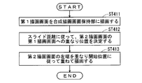
- step ST411 the first drawing screen held in the first drawing screen holding unit 404 is drawn in the composite drawing screen holding unit 408.
- step ST412 the overlapping position of the second drawing screen on the first drawing screen is determined according to the slide distance X0 updated by the slide operation.
- 5 and 6 schematically show a drawing screen composition method in the case where the display positions of the drawing objects displayed on the drawing screen are different from each other.
- the first drawing screen and the second drawing screen are completely overlapped, and the second drawing object is set to a position that masks all the first drawing objects.
- the attention point it is desirable that the first attention point on the first drawing screen and the second attention point on the second drawing screen overlap with each other on the display surface. That is, when the map drawing screen around the vehicle is displayed on the first drawing screen and the task drawing screen for 50 sound search is shown on the second drawing screen, the current position of the vehicle and the current position of the vehicle on the map drawing screen It is desirable that the surrounding facilities match the displayed positions.
- the slide distance X0 is updated to a value other than 0, the overlapping position of the second drawing screen on the first drawing screen according to the position where the user touches the display surface in the gesture operation, for example, and the slide distance X0 based on the operation To decide.
- the distance moved by the user touching the display surface is set as an offset to the overlap start position where the screen edge of the second drawing screen is located.
- a drawing screen superimposed on a predetermined touch operation for example, moving a finger at a predetermined speed or less in a certain direction on the display surface
- a drag mode The mode in which the operation is performed.
- the distance that the user touches and moves the display surface is set as an offset to the overlap start position where the screen edge of the second drawing screen is located, and the user At the same time as the touch operation is finished, the original overlap position before the touch and movement is restored.
- the drawing screen overlaid is moved following a predetermined touch operation (for example, moving a finger in a certain direction on the display surface at a predetermined speed or less), and the original operation is performed simultaneously with the end of the touch operation.
- the operation for returning to the overlapping position is called a shutter operation, and the mode for performing the operation is called a shutter mode.
- the shutter operation and the drag operation can be distinguished by the number of fingers touching the display surface, for example.
- the overlap start position of the second drawing screen is set.
- the drawing screen that is overlaid in the direction specified by the predetermined touch operation is moved, and thereafter the operation to move according to the predetermined inertia is called a skip operation, and the mode for performing the operation is called the skip mode.
- the skip operation is determined under the following conditions and combinations.
- speed set as the predetermined speed in (a) to (c) may be different for each condition.
- step ST413 the second drawing screen is overlaid and drawn (data is overwritten) in accordance with the overlapping position, specifically the overlapping start position. For example, when sliding out to the right side of the display surface, drawing is performed so that the left end of the second drawing screen matches the overlap start position.
- the portion that does not overlap the first drawing screen (P2 in FIGS. 5 and 6) is not displayed on the display surface.
- the first drawing object of the first drawing screen having a width of the slide distance X0 where the second drawing screen does not overlap, and the second drawing object of the second drawing screen (width D1 from the left end of the second drawing screen) P1) in FIGS. 5 and 6 is displayed on the display surface.
- the width D1 in FIGS. 5 and 6 is a length corresponding to the width of the second drawing screen displayed on the composite drawing screen.
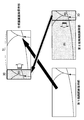
- FIG. 7 By sequentially creating the composite drawing screen as described above, the operation shown in FIG. 7 (slide out by board slide) becomes possible.
- the drawing object a, the drawing object b, the drawing object c, and the second background drawing object are drawn on the first drawing screen on which the drawing object A, the drawing object B, the drawing object C, and the first background drawing object are drawn.
- the second drawing screen is overlapped.
- the first point of interest on the first drawing screen is the drawing object A
- the second point of interest on the second drawing screen is the drawing object a.
- the first background drawing object and the second background drawing object are, for example, rectangular objects painted in cream color with the same size as the drawing screen size.
- a drawing object a, a drawing object b, and a drawing object c are drawn on the second background drawing object.
- (1a), (2a), and (3a) are schematic views of the lower first drawing screen and the upper second drawing screen as viewed from the side, and (1b) (2b) (3b) ) Is a schematic view of the first drawing screen and the second drawing screen as viewed from above.
- the first drawing screen and the second drawing screen are completely overlapped, and the drawing object A, the drawing object B, and the drawing object C are masked by the second background drawing object.
- the second drawing screen is a screen that is smaller than the first drawing screen, it is only necessary that the second drawing screen overlaps an area on the first drawing screen corresponding to the size of the second drawing screen.
- the drawing object a and the drawing object b are displayed on the display surface, but the rightmost drawing object c deviates from the display surface of the input / display unit 1 and is not displayed.
- the drawing object A is displayed, the drawing object B is masked and hidden by the second background drawing object, and the drawing object C is masked and hidden by the second background drawing object.
- the drawing object A which is the first attention point
- the drawing object a which is the second attention point
- the upper second drawing screen moves further to the right, and the drawing object b is also removed from the display surface of the input / display unit 1 and is not displayed.
- the drawing object A and the drawing object B are displayed, but the drawing object C is masked by the second background drawing object and is not displayed.
- the relative positional relationship between the upper second drawing screen and the lower first drawing screen changes as needed.
- step ST431 the first drawing screen held in the first drawing screen holding unit 404 is drawn in the composite drawing screen holding unit 408.
- step ST432 the overlapping position of the second drawing screen on the first drawing screen is determined according to the slide distance X0 updated by the sliding operation.
- FIG. 9 and FIG. 10 schematically show a drawing screen composition method when the display positions of the drawing objects displayed on the drawing screen are different.
- the position is set such that the second drawing screen is completely out of the display surface.
- the slide distance X0 is updated to a value other than 0, the overlapping position of the second drawing screen on the first drawing screen according to the position where the user touches the display surface in the gesture operation, for example, and the slide distance X0 based on the operation To decide.
- the update of the slide distance X0 causes the first drawing point on the first drawing screen to approach the second attention point on the second drawing screen. It is desirable to determine the overlapping position on the first drawing screen.
- step ST433 the second drawing screen is drawn in an overlapping manner according to the overlapping position, specifically, the overlapping start position. For example, when sliding in from the left side of the display surface, the drawing is performed so that the right end of the second drawing screen matches the overlap start position.
- the portion that does not overlap the first drawing screen (P1 in FIGS. 9 and 10) is not displayed on the display surface.
- And P2) in FIG. 10 are displayed on the display surface.
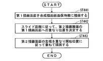
- step ST441 the first drawing screen held in the first drawing screen holding unit 404 is drawn in the composite drawing screen holding unit 408.
- step ST442 the overlapping position of the second drawing screen on the first drawing screen is determined according to the slide distance X0 updated by the sliding operation.
- FIG. 12 and FIG. 13 schematically show a drawing screen composition method when the display positions of the drawing objects displayed on the drawing screen are different.
- the position is set such that the second drawing screen is completely out of the display surface. However, it is outside the display surface on the opposite side (right side) from the case in FIGS.
- the slide distance X0 is updated to a value other than 0, the overlapping position of the second drawing screen on the first drawing screen according to the position where the user touches the display surface in the gesture operation, for example, and the slide distance X0 based on the operation To decide.
- step ST443 the second drawing screen is drawn in an overlapping manner according to the overlapping position, specifically, the overlapping start position. For example, when sliding in from the right side of the display surface, the drawing is performed so that the left end of the second drawing screen coincides with the overlap start position.
- the portion that does not overlap the first drawing screen (P2 in FIGS. 12 and 13) is not displayed on the display surface.
- And P1) in FIG. 13 are displayed on the display surface.
- the left and right arrangement relations are switched and displayed.
- the drawing screen superimposed on the top moves, and the range in which the lower drawing screen can be seen changes according to the movement.
- the sliding method is not limited to the above case, and various variations such as the direction of sliding and the movement of the drawing screen when sliding are conceivable.
- step ST17 in the case of another sliding method will be described with reference to FIGS.
- a composite drawing screen is created, but as a slide method for the drawing screen superimposed on top, the display of the drawing object on the drawing screen superimposed on the display is partially switched, and the drawing screen superimposed on top is displayed.
- the display area is continuously changed (increased or decreased). That is, only the area overlapping the drawing object on the lower drawing screen is changed without changing the display position of the drawing object on the upper drawing screen.
- curtain slide A case where a composite drawing screen is created using the second method (hereinafter, curtain slide) will be described.
- the drawing screen superimposed on top is continuously removed while maintaining the position, and the drawing screen below is displayed
- the drawing screen superimposed on top is referred to as the second drawing screen, but it may be reversed.
- step ST421 the first drawing screen held in the first drawing screen holding unit 404 is drawn in the composite drawing screen holding unit 408.
- step ST422 the overlapping position of the second drawing screen on the first drawing screen is determined according to the slide distance X0 updated by the sliding operation.
- the first drawing screen and the second drawing screen are completely overlapped, and the second drawing object is set to a position that masks all the first drawing objects.
- the attention point it is desirable that the first attention point on the first drawing screen and the second attention point on the second drawing screen overlap with each other on the display surface. That is, when the map drawing screen around the vehicle is displayed on the first drawing screen and the task drawing screen for 50 sound search is shown on the second drawing screen, the current position of the vehicle and the current position of the vehicle on the map drawing screen It is desirable that the surrounding facilities match the displayed positions.
- the slide distance X0 is updated to a value other than 0, the overlapping position of the second drawing screen on the first drawing screen according to the position where the user touches the display surface in the gesture operation, for example, and the slide distance X0 based on the operation To decide.
- the distance (slide distance X0 in FIG. 15) moved by the user touching the display surface is set as an offset to the overlap start position where the screen edge to be removed of the second drawing screen is located.
- a drawing screen superimposed on a predetermined touch operation for example, moving a finger at a predetermined speed or less in a certain direction on the display surface
- the mode in which the operation is performed is called a drag mode.
- the drawing screen overlaid is moved following a predetermined touch operation (for example, moving a finger in a certain direction on the display surface at a predetermined speed or less), and the original operation is performed simultaneously with the end of the touch operation.
- the operation for returning to the overlapping position is called a shutter operation, and the mode for performing the operation is called a shutter mode.
- the shutter operation and the drag operation can be distinguished by the number of fingers touching the display surface, for example.
- an amount that increases with time (the slide distance X0 in FIG. 15 increases with time) is used as an offset.
- the overlapping start position of the second drawing screen is set.
- the drawing screen that is overlaid in the direction specified by the predetermined touch operation is moved, and thereafter the operation to move according to the predetermined inertia is called a skip operation, and the mode for performing the operation is called the skip mode. .
- step ST423 the second drawing screen is drawn in an overlapping manner according to the overlapping position, specifically, the overlapping start position.
- the overlapping position specifically, the overlapping start position.
- drawing is performed so that the left end of the second drawing screen to be removed matches the overlap start position. That is, the position of the second drawing screen that matches the overlap start position is a position that is offset from the left end of the screen by the slide distance X0 on the second drawing screen.
- the portion removed from the first drawing screen (P1 in FIG. 15) is not displayed on the display surface.
- the first drawing object of the first drawing screen having a width of the slide distance X0 where the second drawing screen does not overlap, and the second drawing object of the second drawing screen (width D1 from the right end of the second drawing screen) P2) in FIG. 15 is displayed on the display surface.
- FIG. 16 By sequentially creating the composite drawing screen as described above, the operation shown in FIG. 16 (slide out by curtain slide) becomes possible.
- the second drawing screen on which the drawing object a, the drawing object b, and the drawing object c are drawn is superimposed on the first drawing screen on which the drawing object A, the drawing object B, and the drawing object C are drawn.
- the first point of interest on the first drawing screen is a drawing object B
- the second point of interest on the second drawing screen is a drawing object b.
- the first background drawing object and the second background drawing object are, for example, rectangular objects painted in cream color with the same size as the drawing screen size.
- a drawing object a, a drawing object b, and a drawing object c are drawn on the second background drawing object.
- (1a), (2a), and (3a) are schematic views of the lower first drawing screen and the upper second drawing screen as viewed from the side, and (1b) (2b) (3b) ) Is a schematic view of the first drawing screen and the second drawing screen as viewed from above.
- the overlapping start position of the upper second drawing screen is sequentially updated (1a ⁇ 2a ⁇ 3a or 1b ⁇ 2b ⁇ 3b), and the second drawing screen continuously draws the curtain while maintaining the display position. It is displayed by sliding (curtain slide).
- the first drawing screen and the second drawing screen are completely overlapped, and the drawing object A, the drawing object B, and the drawing object C are masked by the second background drawing object.
- the second drawing screen is a screen that is smaller than the first drawing screen, it is only necessary that the second drawing screen overlaps an area on the first drawing screen corresponding to the size of the second drawing screen.
- the drawing object b and the drawing object c are displayed on the display surface, but the leftmost drawing object a is removed from the display surface of the input / display unit 1 and displayed. Disappear.
- the drawing object A is displayed, the drawing object B is masked and hidden by the second background drawing object, and the drawing object C is masked and hidden by the second background drawing object.
- the relative positional relationship between the upper second drawing screen and the lower first drawing screen is maintained. That is, the first attention point and the second attention point always coincide on the display surface.
- the upper second drawing screen is further removed to the right, and the drawing object b is also removed from the display surface of the input / display unit 1 and is not displayed.
- the drawing object A and the drawing object B are displayed, but the drawing object C is masked by the second background drawing object and is not displayed.
- the drawing object B which is the first attention point
- the drawing object B is displayed at the position where the drawing object b, which is the second attention point, is removed. (See also FIG. 15). At this time, the relative positional relationship between the upper second drawing screen and the lower first drawing screen is maintained.
- the second background drawing object has been described as a single cream color.
- the drawing object a and its vicinity are cream and the drawing object c and its vicinity are pink.
- the drawing background color near the drawing object c in (2a) and (3a) is a color close to the same pink.
- the slide method described above changes the range in which the lower drawing screen can be seen by changing the display area continuously while maintaining the display position of the drawing screen superimposed on top.
- the slide method is not limited to the above case, and various variations are conceivable, such as the direction in which the fluctuation progresses (such as spreading around the touch position) and the display method of the drawing screen at the time of switching the display (flashing or fading).
- the slide method described above allows the user to perform a slide operation no matter where the user touches the area where the second drawing screen is displayed.
- the second drawing screen that accepts the slide operation is displayed.
- the range may be limited.
- it may be configured to receive a slide on the second drawing screen when a gesture indicating a slide is performed near the boundary where the second drawing screen is displayed.
- an area on the second drawing screen that accepts a slide operation may be displayed with an icon or the like.
- normal operation transitions by drag operation, skip operation, and simple touch operation can be received side by side, and a user-friendly device can be provided.
- the second background drawing object is a cream-colored rectangular object having the same size as the drawing screen.
- the second background drawing object is not limited to a rectangle, but is a trapezoidal, elliptical, or perforated object.
- the color may be a gradation or a pattern instead of a light color, and a display with a good design for the user can be provided.
- first drawing object and the second drawing object have been described as being stored in the first information storage unit 2 and the second information storage unit 3, respectively.
- Both or one of the drawing objects may be generated by
- the vehicle position mark and the like may be created by the overall control unit 402 by a program.
- the overall control unit 402 may generate both or one of the background drawing objects by software processing.
- the method of rendering the background drawing object which is a rectangular drawing object, on the drawing screen has been described.
- the method of generating the background drawing object is not limited to this method.
- the drawing screen itself 1 has a function of generating a background color corresponding to the background drawing object
- the overall control unit 402 may set the background colors of the first drawing screen holding unit 404 and the second drawing screen holding unit 406 by software processing.
- the overall control unit 402 performs the respective background by software processing.
- a color may be set.
- the drawing object referred to in the present invention is a concept including a display object that is finally displayed on the input / display unit 1 by the above-described software processing.
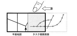
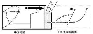
- the plane map of the road is the first drawing screen
- the task drawing screen displaying the task information of the 50 sound search for the surrounding facilities is the second drawing screen
- the task drawing screen is superimposed on the plane map.
- the second background drawing object is transparent, but in FIG. 17, the second background drawing object is colored in order to clarify the difference from the first background drawing object.
- the task drawing screen can be located outside the display surface and not displayed completely, but the left end portion of the task drawing screen is For example, if it is displayed on the right end portion of the planar map by a predetermined operation such as voice recognition, the above sliding method can be easily performed using that portion.
- a limit value may be set in a range where task drawing screens can overlap. That is, you may set the upper limit boundary how far it overlaps.
- the road map is the first drawing screen
- the task drawing screen displaying the simplified route map is the second drawing screen
- the task drawing screen is superimposed on the plane map.
- the first background drawing object and the second background drawing object are illustrated as having different colors for easy understanding, but the present invention is not limited to this.
- the planar map corresponds to the entire display surface, and the left end portion (thread) of the task drawing screen is displayed at the right end portion of the planar map.
- the above sliding method can be easily performed using the left end portion (thread) of the task drawing screen.
- the task drawing screen is touched and slid (slide-in by board slide). With this operation, the drawing object related to the task information can be displayed so as to overlap the drawing object related to the map information.
- the selection of station A on the task drawing screen changes the display range on the plane map in conjunction (changes the display so that station A is the center).
- the task of searching for station A is achieved by the plane map and the task drawing screen. That is, “A station” is selected on the task drawing screen, the display range on the planar map is changed in conjunction with the selection, and A station in the simplified route map is displayed on the map.
- the planar map and the task drawing screen overlap, and the station A on the map and the station A on the simplified route map are displayed, so that the relationship between the drawing objects on the two drawing screens can be easily grasped.
- the plane map is determined in conjunction with the selection on the task drawing screen, but the task (“Find station A”) for which the composite drawing screen is created exists before the composition.
- the plane map and the task drawing screen may be created at a time according to the creation purpose. That is, it is not necessary to be linked to the operation on the task drawing screen, and each drawing screen may be created according to the creation operation.
- the display area of the task drawing screen is enlarged in order to select station B on the task drawing screen, which is necessary for the next task ("search for B station").
- the station B is selected on the task drawing screen (FIG. 24), and the display is changed to the center of the station B (FIG. 25).
- the task of searching for station B is achieved by the plane map and the task drawing screen. That is, “B station” is selected on the task drawing screen, the display range in the planar map is changed in conjunction with the selection, and B station in the simplified route map is displayed on the map.
- the planar map and the task drawing screen overlap, and the station B on the map and the station B on the simplified route map are displayed, so that the relationship between the drawing objects on the two drawing screens can be easily grasped.
- the input / display unit 1 has a configuration in which an input unit that receives user input information and a display unit that displays a drawing screen based on the received input information and operation control by the control unit 4 are integrated.
- achieves these functions may be provided separately.
- the information to be displayed is not limited to the drawing object on the drawing screen, and various information according to the user's request can be displayed.
- the operation can be easily performed by using the touch panel as in the present embodiment and changing the overlap of the drawing screens by the gesture operation. That is, the control of the conventional map display device is performed by touching an operation icon displayed on the touch panel or by a mechanical switch or dial operation, and the user interface is not necessarily easy to use.
- a user interface that is easy to use can be realized by using a gesture operation represented by a mobile terminal having a touch panel, which is called a so-called smartphone or the like.
- the operation time is limited, for example, when the map display device mounted on the vehicle is operated. Furthermore, the degree of freedom of fluctuation of the overlap (the direction of movement, the effect at the time of introduction and removal, etc.) is high, and it is possible to meet the requirements including the user's entertaining elements.
- the input / display unit 1 is not limited to a normal touch panel, and may be a three-dimensional touch panel capable of detecting the proximity and contact of a finger using a capacitance detection type touch panel.
- the first information storage unit 2 and the second information storage unit 3 may be different storage media as shown in FIG. 1, or may be a case where both are included in one storage medium. Moreover, the case where the drawing object regarding map information, task information, etc. are acquired by communicating with the storage medium provided outside may be sufficient.
- the slide method in the present embodiment is an example, and in the above slide display mode, the drawing screen may be updated by a method other than the slide method.
- travel operation restrictions may be imposed. For example, when the vehicle is traveling, sliding of the drawing screen or operation of the task drawing screen may be disabled. It is also possible to indicate that the operation is impossible by changing the color of the screen.
- the scales of the map overlaid and the map below it do not have to match.
- the upper drawing screen and the lower drawing screen may not have the same size. Note that the drawing screen does not have to be the size of the entire display surface.
- the drawing screen displaying the drawing objects related to the task information may be such that the drawing objects related to characters are displayed on a transparent drawing screen. Note that the drawing objects displayed on the first drawing screen and the second drawing screen can be interchanged with each other.
- a drawing object related to information for displaying settings common to the upper drawing screen may be displayed regardless of the update of the upper drawing screen.
- the number of drawing screens to be superimposed is not limited to two, and may be three or more.
- one drawing object masks at least one other drawing object in an overlapping portion between one drawing screen and at least one of the other two drawing screens.
- one drawing screen when one drawing screen is slid, it may slide independently from the other drawing screens, but any other drawing screen may be subordinately slid.
- an operation input related to a user's drawing screen display is received, the first drawing object related to the map information on the first drawing screen, and the second drawing on the second drawing screen.
- the input / display unit 1 for displaying an object, and the overlapping state of the first drawing screen and the second drawing screen are controlled according to the user's operation input received by the input / display unit 1, and the first drawing screen and the second drawing screen are controlled.
- one of the first drawing object and the second drawing object includes the control unit 4 that masks the other and outputs it to the input / display unit 1, whereby the relationship between the drawing objects on the drawing screen It is possible to make it easy to grasp.
- one side masks the other to suppress the display of drawing objects other than the drawing object whose relationship is to be grasped, or the masking is canceled to display the drawing object as a drawing object. It can be displayed in a close display area.
- one of the first drawing object and the second drawing object is a drawing object related to map information, and the other is used together with the map information to perform a specific task. Since the drawing object is related to the task information that achieves the above, the relationship between the drawing object related to the map information and the drawing object related to the task information can be grasped, and a specific task can be easily executed.
- the control unit 4 links the drawing object on the map drawing screen for displaying the map information in conjunction with the operation on the task drawing screen for displaying the task information.
- the drawing object drawing object related to task information
- the drawing object indicating the station in the route map is displayed.
- a planar map with a display range centered on the drawing object at that station can be displayed, and the relationship between each other's drawing objects (drawing objects related to map information and task information) is easy. Can grasp. Therefore, task achievement can be easily realized.
- the control unit 4 slides the other of the first drawing screen and the second drawing screen to make the first drawing screen and the second drawing screen appear.
- the second drawing object whose relationship with the first drawing object is to be grasped can be displayed while being continuously changed on the first drawing screen. It becomes easy to compare the first drawing object and the second drawing object.
- the board slide in which the drawing object on the drawing screen moves in the sliding direction in conjunction with the slide on the drawing screen, and the input / display unit By including the curtain slide in which the position of the drawing object displayed in 1 does not change, it is possible to easily grasp the relationship between the drawing objects on the drawing screen.
- the drawing object on the second drawing screen moves in the sliding direction in conjunction with the slide on the drawing screen, so that the second drawing object whose relationship with the first drawing object is to be grasped in the vicinity of the first drawing object. It is possible to display while continuously moving, and it is easy to compare the first drawing object and the second drawing object. That is, when grasping the relationship between the first drawing object and the second drawing object, it is possible to save the user from having to memorize and compare the features and the like.
- the second drawing object for which the relationship with the first drawing object is to be grasped can always be displayed immediately above the first drawing object, and the position corresponding to the first drawing object is removed from the corresponding first drawing object. Since the drawing object can be displayed, it is easy to grasp the relationship between the first drawing object and the second drawing object.
- the first drawing object and the second drawing object include the position of the vehicle (moving body) on the map, the moving route of the vehicle, and the destination of the vehicle.
- the plane map around the current position of the vehicle and the map displaying the 50-sound search result of the facilities around the current position can be displayed in an overlapping manner.
- a planar map around the current position of the vehicle and a map displaying the 50-sound search result of a facility around a certain point on the set travel route can be overlaid and the degree of overlap can be controlled.
- the drawing object related to the map information of the current position of the vehicle and the drawing object related to the information about the facility around the point on the moving route can be easily compared, so that it can be used as a judgment material for route change or the like.
- a planar map around the current position of the vehicle and a map displaying the 50-sound search result of the facility around the set destination can be displayed in an overlapping manner, and the vehicle current can be controlled by controlling the degree of overlap. Since the drawing object related to the facility information at the destination can be easily referred to while the drawing object related to the map information of the position is acquired, it can be used as a material for studying the schedule after arriving at the destination.
- the first drawing screen has a preset first attention point
- the second drawing screen has a preset second attention point.
- the display position of the first attention point and the display position of the second attention point are always coincident (curtain slide or the like)
- the attention points that the user wants to grasp the relationship are close to each other on the display surface. Can be displayed, or only one of them can be displayed, making it easy to grasp the relationship between them.
- the fully overlapped state is the second drawing screen within a predetermined range of the first drawing screen.
- the second drawing object can realize a state in which all the corresponding first drawing objects are masked.
- the first drawing screen displays at least one first drawing object
- the second drawing screen displays at least one second drawing object.
- at least one of the first drawing object and the second drawing object includes a drawing object related to map information, and the first drawing screen and the second drawing screen have the same or different sizes, and (a) a user A step of accepting an operation input relating to the drawing screen display, a step of (b) performing a drawing screen display of a plurality of drawing screens, and (c) prior to step (b), a user operation input received in step (a).
- any constituent elements in the present embodiment can be modified or omitted within the scope of the invention.
- SYMBOLS 1 Input and display part 2 1st information storage part, 3rd 2nd information storage part, 4 control part, 401 input analysis part, 402 whole control part, 403 1st information drawing part, 404 1st drawing screen holding part, 405 2nd information drawing part, 406 2nd drawing screen holding part, 407 Composite drawing part, 408 Composite drawing screen holding part.
Landscapes
- Engineering & Computer Science (AREA)
- Radar, Positioning & Navigation (AREA)
- Remote Sensing (AREA)
- Physics & Mathematics (AREA)
- General Physics & Mathematics (AREA)
- Automation & Control Theory (AREA)
- Theoretical Computer Science (AREA)
- Human Computer Interaction (AREA)
- Mathematical Physics (AREA)
- Business, Economics & Management (AREA)
- Educational Administration (AREA)
- Educational Technology (AREA)
- Navigation (AREA)
- User Interface Of Digital Computer (AREA)
- Instructional Devices (AREA)
Description
本発明は、地図表示装置および地図表示方法に関し、特に、複数の描画画面を表示面に表示する地図表示装置および地図表示方法に関するものである。
複数の描画画面を表示面に表示する地図表示方法として、例えば表示面を2つに分割し、それぞれの表示領域において、例えば車両の現在位置を中心とする地図描画画面を表示するものがあった(特許文献1参照)。ここで地図描画画面とは、地図を表示する場合の、道路線、文字、地形、建物、アイコン、背景色(透明、または半透明であってもよい)、付属する情報等のオブジェクトである描画オブジェクトを描画した画面のことであり、表示面とは、それらの地図描画画面を実際に表示するディスプレイのことである。地図描画画面は、表示面における所定の表示領域において、表示されることになる。
当該地図表示方法によれば、例えば、一方の表示領域において経路誘導に関する地図描画画面を表示し、他方の表示領域においては異なる縮尺で同様の経路誘導に関する地図描画画面を表示することにより、また、タスク情報に関する描画オブジェクトを表示するタスク描画画面をどちらかの表示領域に表示することにより、ユーザにとって有益な地図表示方法を実現することが可能であった。ここで、タスク情報とは、地図情報とともに用いられることで特定のタスクを達成させる情報であり、地図上の位置に従った配置で表示されるものに限らない。
また、特許文献1に示す地図表示方法では、左右の表示領域の境界を可変とすることで、その利便性をさらに高めている。
しかし、上記のような地図表示方法によって同時に表示された複数の描画画面では、それぞれの描画画面に表示された描画オブジェクト同士の関係性の把握が、必ずしも容易でないという問題があった。
例えば、車両の現在位置を示す描画画面同士において、一方を高速道路の地図描画画面、他方を一般道路の地図描画画面とするとき、また、一方を平面表示の地図描画画面、他方を周辺施設の50音検索のタスク描画画面とするときでも、両表示領域に表示された描画画面における描画オブジェクトがどのように対応しているかを把握するには、ユーザが両表示領域を交互に見比べ、目印となる建物等を頼りに判断する必要があった。
本発明は、上記のような問題を解決するためになされたものであり、複数の描画画面を表示する地図表示装置およびその方法であって、描画画面における描画オブジェクト間の関係性の把握を容易にすることを可能とする地図表示装置およびその方法の提供を目的とする。
本発明は、第1描画画面および第2描画画面を含む複数の描画画面を、少なくとも部分的に重ね表示可能な地図表示装置において、前記第1描画画面は、少なくとも1つの第1描画オブジェクトを表示し、前記第2描画画面は、少なくとも1つの第2描画オブジェクトを表示し、前記第1描画オブジェクトおよび前記第2描画オブジェクトのうち少なくとも一方が地図情報に関する描画オブジェクトを含み、前記第1描画画面および前記第2描画画面は、同じまたは異なる大きさであって、ユーザの描画画面表示に関する操作入力を受け付ける入力部と、前記入力部で受け付けたユーザの操作入力に応じて、前記第1描画画面および前記第2描画画面の重なり具合を制御し、前記第1描画画面および前記第2描画画面の重なり部分では、前記第1描画オブジェクトおよび前記第2描画オブジェクトの一方が他方をマスクして表示部に出力する制御部とを備えることを特徴とする。
本発明は、第1描画画面および第2描画画面を含む複数の描画画面を、少なくとも部分的に重ねて表示する地図表示方法であって、前記第1描画画面は、少なくとも1つの第1描画オブジェクトを表示し、前記第2描画画面は、少なくとも1つの第2描画オブジェクトを表示し、前記第1描画オブジェクトおよび前記第2描画オブジェクトのうち少なくとも一方が地図情報に関する描画オブジェクトを含み、前記第1描画画面および前記第2描画画面は、同じまたは異なる大きさであって、(a)ユーザの描画画面表示に関する操作入力を受け付けるステップと、(b)複数の前記描画画面の描画画面表示を行うステップと、(c)前記ステップ(b)に先立って、前記ステップ(a)において受け付けたユーザの操作入力に応じて、前記第1描画画面および前記第2描画画面の重なり具合を制御し、前記第1描画画面および前記第2描画画面の重なり部分では、前記第1描画オブジェクトおよび前記第2描画オブジェクトの一方が他方をマスクするステップとを備えることを特徴とする。
本発明によれば、第1描画画面および第2描画画面を含む複数の描画画面を、少なくとも部分的に重ね表示可能な地図表示装置において、前記第1描画画面は、少なくとも1つの第1描画オブジェクトを表示し、前記第2描画画面は、少なくとも1つの第2描画オブジェクトを表示し、前記第1描画オブジェクトおよび前記第2描画オブジェクトのうち少なくとも一方が地図情報に関する描画オブジェクトを含み、前記第1描画画面および前記第2描画画面は、同じまたは異なる大きさであって、ユーザの描画画面表示に関する操作入力を受け付ける入力部と、前記入力部で受け付けたユーザの操作入力に応じて、前記第1描画画面および前記第2描画画面の重なり具合を制御し、前記第1描画画面および前記第2描画画面の重なり部分では、前記第1描画オブジェクトおよび前記第2描画オブジェクトの一方が他方をマスクして表示部に出力する制御部とを備えることにより、描画画面における描画オブジェクト間の関係性の把握を容易にすることを可能とする。
本発明によれば、第1描画画面および第2描画画面を含む複数の描画画面を、少なくとも部分的に重ねて表示する地図表示方法であって、前記第1描画画面は、少なくとも1つの第1描画オブジェクトを表示し、前記第2描画画面は、少なくとも1つの第2描画オブジェクトを表示し、前記第1描画オブジェクトおよび前記第2描画オブジェクトのうち少なくとも一方が地図情報に関する描画オブジェクトを含み、前記第1描画画面および前記第2描画画面は、同じまたは異なる大きさであって、(a)ユーザの描画画面表示に関する操作入力を受け付けるステップと、(b)複数の前記描画画面の描画画面表示を行うステップと、(c)前記ステップ(b)に先立って、前記ステップ(a)において受け付けたユーザの操作入力に応じて、前記第1描画画面および前記第2描画画面の重なり具合を制御し、前記第1描画画面および前記第2描画画面の重なり部分では、前記第1描画オブジェクトおよび前記第2描画オブジェクトの一方が他方をマスクするステップとを備えることにより、描画画面における描画オブジェクト間の関係性の把握を容易にすることを可能とする。
この発明の目的、特徴、局面、および利点は、以下の詳細な説明と添付図面とによって、より明白となる。
<実施の形態1>
<構成>
図1を参照し、実施の形態1にかかる地図表示装置の概念的な全体構成を説明する。なお、地図表示装置についてはその用途を特に限定しないが、以下の実施の形態では移動体としての車両に搭載されたカーナビゲーション装置を想定し、説明する。
<構成>
図1を参照し、実施の形態1にかかる地図表示装置の概念的な全体構成を説明する。なお、地図表示装置についてはその用途を特に限定しないが、以下の実施の形態では移動体としての車両に搭載されたカーナビゲーション装置を想定し、説明する。
図1に示すように地図表示装置は、ユーザの意図に沿う入力情報を受け取り、情報を表示する入力兼表示部1と、入力兼表示部1において受け取った入力情報に基づいて、入力兼表示部1における描画画面の表示動作を制御する制御部4と、制御部4における動作制御の際に、参照される地図情報、タスク情報に関する描画オブジェクト等が格納された、第1情報格納部2および第2情報格納部3とを備える。
描画オブジェクトは、描画画面内に表示される、道路線、文字、地形、建物、アイコン、背景色(透明、または半透明であってもよい)、付属する情報等のオブジェクトである。描画オブジェクトに含まれる背景色(背景描画オブジェクト)としては、一様に色が塗られたものに限らず、グラデーションが施されたものや、描画画面内を部分的に塗るものであってもよい。
入力兼表示部1は、例えばタッチパネル(タッチパネル付き表示装置)によって実現され、ユーザの表示面への接触(タッチ)を受け、表示面上におけるタッチ位置および動作等からユーザの意図を解析する。ユーザの意図として想定されるものには、表示されている描画画面に対する操作や、経路探索指示、内蔵されるオーディオ機器等に対する操作等がある。描画画面に対する操作とは、例えば縮尺の変更や、表示する地図上の位置の変更(スクロール)、現在位置周辺の情報検索、当該情報の比較等である。
第1情報格納部2および第2情報格納部3は、地図情報、タスク情報に関する描画オブジェクト等を格納する。地図情報に関する描画オブジェクトの具体例としては、地形等を示す地図データ、当該地図上の位置に対応付けられた道路データ、建物データ(図形、形状)、背景色データ等を格納している。ここで建物データとは、建物自体の立体形状や、種別、名称等を示すデータである。タスク情報に関する描画オブジェクトの具体例としては、50音検索データ、簡略路線データ等を格納している。どちらの格納部がどちらの情報を格納していてもよい。なお、第1情報格納部および第2情報格納部3に格納される情報は、地図情報、タスク情報に関する描画オブジェクトに限られるものではなく、入力兼表示部1に表示するための様々な情報を格納することができる。
第1情報格納部2および第2情報格納部3は、具体的には、ハードディスクドライブやメモリーカード、DVDやブルーレイディスク等で実現される。
制御部4は、地図表示装置に備えられる各機能部を制御し、入力兼表示部1に描画画面を表示させる。図1に示すように、ユーザからの入力情報を解析することによって、描画画面の作成に必要となる、地図情報、タスク情報に関する描画オブジェクトに関する抽出条件を形成する。例えば、制御部4が入力情報を解析して、ユーザの意図が「周辺施設の情報の検索」であった場合に、現在位置周辺の一般道路の地図情報の描画オブジェクトと、現在位置周辺の施設名を50音検索するタスク情報の描画オブジェクトとを抽出する条件を形成することができる。
さらに制御部4は、当該抽出条件に基づいて第1情報格納部2および第2情報格納部3から地図情報、タスク情報に関する描画オブジェクトをそれぞれ抽出し、入力兼表示部1に所望の態様で表示させる。制御部4は、具体的にはコンピュータ(CPU)とそのプログラムで実現されるものである。
図2は、図1に示す地図表示装置の構成において、特に制御部4の概念的構成を詳細に示したものである。
入力兼表示部1から入力された入力情報を解析する入力解析部401と、入力解析部401における解析結果に基づいて、第1情報描画部403および第2情報描画部405、合成描画部407を制御し、入力兼表示部1に描画画面を表示させる全体制御部402と、第1情報格納部2において格納された描画オブジェクトである第1描画オブジェクトを抽出し、第1描画画面保持部404に、当該第1描画オブジェクトによる描画画面である第1描画画面を描画する第1情報描画部403と、第2情報格納部3において格納された描画オブジェクトである第2描画オブジェクトを抽出し、第2描画画面保持部406に、当該第2描画オブジェクトによる描画画面である第2描画画面を描画する第2情報描画部405と、第1描画画面を保持する第1描画画面保持部404と、第2描画画面を保持する第2描画画面保持部406と、第1描画画面と第2描画画面とを合成した合成描画画面を、合成描画画面保持部408に描画する合成描画部407と、合成描画部407で作成した合成描画画面を保持する合成描画画面保持部408とを備える。合成描画画面保持部408に保持された合成描画画面は、描画画面として入力兼表示部1において表示される。
ここで、第1描画オブジェクトおよび第2描画オブジェクトのうちの少なくとも一方は地図情報に関する描画オブジェクトであるが、他方にはタスク情報に関する描画オブジェクトが含まれていてもよい。
入力解析部401は、ユーザの意図による入力情報を解析する。すなわち、描画画面表示内容とユーザが表示面にタッチした位置や動作等の条件を解析し、ユーザの意図に沿う操作(機器操作等)を識別する。ここで、ユーザのタッチパネル操作には、従来からある単なるアイコンをタッチする単純タッチ操作(通常タッチ操作)と、動きのある「ジェスチャー操作」すなわち、後述の「引きずり操作」や「飛ばし操作」等がある。
全体制御部402では、当該解析結果に基づいて必要となる地図情報、タスク情報に関する描画オブジェクトを特定し、第1情報描画部403に、第1情報格納部2から第1描画オブジェクトを抽出させ、第2情報描画部405に、第2情報格納部3から第2描画オブジェクトを抽出させる。
第1情報描画部403は、抽出した第1描画オブジェクトから第1描画画面を形成し、第1描画画面保持部404(メモリ部)に描画する。
第2情報描画部405は、抽出した第2描画オブジェクトから第2描画画面を形成し、第2描画画面保持部406(メモリ部)に描画する。
第1情報描画部403および第2情報描画部405では、例えば、車両の現在位置データ、経路探索動作によって得られた車両の目的地までの経路データ等の、装置内で生成された情報についても、それぞれで形成した描画画面(第1描画画面、第2描画画面)に付加して、対応する描画画面保持部に描画することができる。
さらに全体制御部402では、第1描画画面保持部404に保持された第1描画画面と第2描画画面保持部406に保持された第2描画画面とを合成描画部407に合成させ、合成描画画面保持部408(メモリ部)に描画させる。合成描画画面は、合成描画画面保持部408(メモリ部)において保持された後、入力兼表示部1において表示される。
合成描画部407は、第1描画画面と第2描画画面とが、それぞれの描画内容を保持したまま、全部あるいは部分的に重なって表示されるように合成し、合成描画画面とする。第1描画画面と第2描画画面とが重なって表示されることで、そのうち下の描画画面の描画オブジェクトが、上の描画画面の描画オブジェクトにマスクされる(上の描画画面の描画オブジェクトの表示によって、下の描画画面の描画オブジェクトが非表示となる)ことになる。
重なって表示される部分は、通常は上に重なっている描画画面の描画オブジェクトが見える状態となっているが、重なり具合を制御することにより、下に表示されている描画画面の描画オブジェクトを見ることができる。なお、ここでいう「上下」とは、表示面の法線方向における上下であり、より手前側を「上」とするものであるが、実際には描画画面のデータを概念的に重ねているものである。
合成される第1描画画面および第2描画画面はそれぞれ、あらかじめ設定された第1注目点、第2注目点を有することができる。
ここで第1注目点および第2注目点とは、ユーザが描画画面上で特に注目する点を指し、ユーザが第1描画画面と第2描画画面との双方を参照する際に比較対象とする点として主観的に定義される点である。例えば、車両の周辺地図における車両の現在位置、目的地周辺地図における目的地の位置である。
合成される描画画面それぞれに表示される描画オブジェクト間には、所定の関連性を有することができる。所定の関連性としては、車両の地図上の位置が一致または近傍であることによる関連、車両の現在位置と目的地との間等の移動経路上の関連、同車両の現在の走行路と過去の走行履歴といった時間的関連等がある。
描画画面を重ねる順序は、ユーザの意図に沿うように、例えば、描画オブジェクトの組み合わせごとに決定することができる。また、重ねる順序の変更も随時可能である。特定の組み合わせには、特定の上下関係を定義してもよい。
<動作>
次に、実施の形態1にかかる地図表示装置の動作の概要について説明する。
次に、実施の形態1にかかる地図表示装置の動作の概要について説明する。
本発明にかかる地図表示装置は、上に重ねられる描画画面の表示位置を所定の操作で更新し、上の描画画面の描画オブジェクトと、下の描画画面の描画オブジェクトとを比較することで、複数の描画画面における描画オブジェクトの関係性を容易に把握させるものである。動作に際しては、制御部4の特に全体制御部402において各機能部の制御が行われる。
以下の説明では、上に重ねられる描画画面の表示位置を更新する所定の操作の具体的方法として、スライド方法を用いる。スライド方法とは、以下に示す、上に重ねられる描画画面全体が連続的に移動する、すなわち、上に重ねられる描画画面の描画オブジェクトがスライドに連動してスライド方向に移動する第1の方法、または、上に重ねられる描画画面の描画オブジェクトの表示を部分的に表示を切り替え、上に重ねられる描画画面の表示領域を連続的に変動(増やすまたは減らす)させていく、すなわち、上に重ねられる描画画面の描画オブジェクトの表示位置は変化させずに、下の描画画面の描画オブジェクトと重なる領域だけを変化させる第2の方法である。なお、上に重ねられる描画画面の表示位置がどのように更新されるかは、ユーザの表示面に対する操作態様や、描画画面の組み合わせに対してあらかじめなされた設定等によって変更することができる。
具体的な動作について、図3を参照しつつ、説明する。
まずステップST10において、地図表示装置の電源を入れ、入力兼表示部1において初期画面を表示させる。初期画面は通常表示モード、すなわち、通常タッチ操作を受け付けるモードとすることができる。
次にステップST11において、入力兼表示部1において初期画面に所定の操作を行い、スライド表示モードに遷移させる。ここでスライド表示モードとは、上記のスライド方法を用いて、上に重ねられる描画画面の表示位置を更新できるモードのことである。
当該遷移は、初期画面における、例えばタッチ操作、ボタン操作、アイコン操作、ジェスチャー操作、音声認識等によって行うことができる。
スライド表示モードに遷移しているか否かを確認する場合には、全体制御部402に格納された、モードの種類を記憶するパラメータを参照することにより行うことができる。例えば、パラメータの値が所定の閾値より大きいまたは小さいことをもって、スライド表示モードであるか否かを判断できる。パラメータの値は、ユーザからの入力に応じて変更されるものであってもよいし、あらかじめ設定した条件(車両状態や表示面における表示状態を含む)で自動的に変更されるものであってもよい。また入力兼表示部1において、当該モードであるか否かを示すアイコン等が表示されるように設定しておくと、容易にモードの確認ができ便利である。
スライド表示モードに遷移したら、ステップST12において、スライド距離X0を0に設定する。
次にステップST13において、第1描画画面および第2描画画面を作成する。当該作成は、上記のようにユーザの入力情報に従って、第1情報描画部403および第2情報描画部405において行う。作成した第1描画画面は第1描画画面保持部404に、第2描画画面は第2描画画面保持部406に、それぞれ描画され保持される。
次にステップST14において、上に重ねられる描画画面の表示位置を更新する所定の操作(スライド操作)が行われたか否かを検出する。当該検出は、入力兼表示部1におけるジェスチャー操作等を、入力解析部401において解析することで行う。スライド操作を検出した場合にはステップST15へ、スライド操作を検出しない場合にはステップST16へそれぞれ進む。
次にステップST15において、スライド操作に基づいてスライド距離X0を更新する。
次にステップST16において、第1描画画面および第2描画画面において表示された描画オブジェクトを更新する。当該更新は、車両の移動等によって時々刻々変化する、描画画面内に表示される車両周辺の範囲や、描画オブジェクトとして表示される地図情報等(道路データ、建物データ、走行履歴を示すデータ等を含む)およびタスク情報等(50音検索データ、簡略路線データ等を含む)を更新するものである。
次にステップST17において、スライド距離X0に従って、上に重ねられる描画画面の表示位置を決定し、第1描画画面と第2描画画面とから合成描画画面を作成する。そして、入力兼表示部1に描画、すなわち表示する。詳細については後述する。
次にステップST18において、スライド表示モードを終了する所定の操作を検出する。当該操作が検出された場合にはステップST19へ進み、当該操作が検出されない場合にはステップST14へ戻る。スライド表示モードの終了は、例えばタッチ操作、ボタン操作、アイコン操作、ジェスチャー操作、音声認識等によって行うことができる。
次にステップST19において、通常表示モードに遷移し、ステップST11に戻る。
次に、ステップST17の詳細について、図4~7を参照しつつ説明する。当該ステップでは合成描画画面の作成が行われるが、上に重ねた描画画面のスライド方法として、上に重ねられた描画画面全体を連続的に移動する、すなわち、上に重ねられる描画画面の描画オブジェクトがスライドに連動してスライド方向に移動する第1の方法(以下、ボードスライド)を用いて合成描画画面の作成を行う場合を説明する。特に、ボードスライドによるスライドアウト、すなわち、描画画面同士が全て重なった状態(全重ね状態)から、上に重ねた描画画面が移動し、表示面外へ出ていく方法を用いる場合を説明する。なお以下では、上に重ねる描画画面を第2描画画面とするが、逆であってもよい。
まずステップST411において、第1描画画面保持部404に保持された第1描画画面を合成描画画面保持部408に描画する。
次にステップST412において、スライド操作によって更新したスライド距離X0に従って、第2描画画面の第1描画画面への重なり位置を決定する。図5および図6に、描画画面に表示される描画オブジェクトの表示位置がそれぞれ異なる場合の、描画画面の合成方法を模式的に示す。
スライド距離X0が0である場合には、第1描画画面と第2描画画面とが完全に重なり、第2描画オブジェクトが第1描画オブジェクトを全てマスクする位置にする。注目点が設定されている場合には、第1描画画面における第1注目点と第2描画画面における第2注目点とが、表示面において重なって一致するような位置にしておくことが望ましい。すなわち、第1描画画面において車両周辺の地図描画画面が、第2描画画面において50音検索のタスク描画画面が示されている場合には、地図描画画面における車両の現在位置と、車両の現在位置周辺の施設が表示された位置とが一致するような位置にすることが望ましい。
スライド距離X0が0以外に更新された場合には、ユーザが例えばジェスチャー操作において表示面にタッチした位置、動作に基づくスライド距離X0に応じて、第2描画画面の第1描画画面への重なり位置を決定する。
例えば、ユーザが表示面にタッチし移動した距離(図5および図6におけるスライド距離X0)をオフセットとして、第2描画画面の画面端が位置する重なり開始位置に設定する。当該操作のように、所定のタッチ操作(例えば、表示面上のある方向へ所定の速度以下で指を動かす)に追随して上に重ねられる描画画面が移動する操作を引きずり操作といい、当該操作を行うモードを引きずりモードと呼ぶ。
また例えば、ユーザが表示面にタッチし移動した距離(図5および図6におけるスライド距離X0)をオフセットとして、第2描画画面の画面端が位置する重なり開始位置に設定し、ユーザが表示面にタッチする操作を終了すると同時に、タッチし移動する前の、元の重なり位置に戻す。当該操作のように、所定のタッチ操作(例えば、表示面上のある方向へ所定の速度以下で指を動かす)に追随して上に重ねられる描画画面を移動させ、タッチ操作の終了と同時に元の重なり位置まで戻す操作をシャッター操作といい、当該操作を行うモードをシャッターモードと呼ぶ。シャッター操作と引きずり操作とは、例えば、表示面にタッチする指の本数で区別することもできる。
また例えば、ユーザが表示面にタッチしトランプを飛ばすような動作(はじくような動作)をした場合には、時間とともに増加する量(図5および図6におけるスライド距離X0が時間とともに増加する)をオフセットとして、第2描画画面の重なり開始位置を設定する。当該操作のように、所定のタッチ操作で指定した方向に上に重ねられる描画画面を移動させ、以降は所定の慣性に従って移動させる操作を飛ばし操作といい、当該操作を行うモードを飛ばしモードと呼ぶ。
飛ばしモードでは、例えば次の条件や組み合わせで飛ばし操作を判断する。(a)タッチパネルにタッチした後、表示面上のある方向へ所定の速度以上で指をすばやく動かした場合、(b)タッチパネルを押した後、表示面上のある方向へ予め定められた所定の速度以上で、押圧を下げて指をすばやく動かす場合、(c)タッチパネルにタッチした後、表示面上のある方向へ予め定められた所定の速度以上で指をすばやく動かし、指をタッチパネルからやや離す場合である(ただし、この場合には、3次元位置を認識するタッチパルが必要である)。
なお、(a)~(c)における所定の速度として設定される速度は、それぞれの条件ごとに異なる速度であってもよい。
次にステップST413において、重なり位置、具体的には重なり開始位置に従って、第2描画画面を重ねて描画(データを上書き)する。例えば、表示面の右側へスライドアウトする場合には、第2描画画面の左端が重なり開始位置に一致するように重ねて描画する。
第1描画画面に重なりきらない部分(図5および図6におけるP2)は、表示面には表示しない。この状態においては、第2描画画面が重ならないスライド距離X0の幅の第1描画画面の第1描画オブジェクトと、第2描画画面左端から幅D1分の、第2描画画面の第2描画オブジェクト(図5および図6におけるP1)とが、表示面に表示されることになる。ここで図5および図6における幅D1は、合成描画画面において表示される第2描画画面の幅に相当する長さである。
上記のような合成描画画面の作成を順次行うことで、図7に示す動作(ボードスライドによるスライドアウト)が可能となる。図7では、描画オブジェクトA、描画オブジェクトB、描画オブジェクトC、第1背景描画オブジェクトを描画した第1描画画面上に、描画オブジェクトa、描画オブジェクトb、描画オブジェクトc、第2背景描画オブジェクトを描画した第2描画画面を重ねている。仮に、第1描画画面における第1注目点を描画オブジェクトA、第2描画画面における第2注目点を描画オブジェクトaとする。第1背景描画オブジェクトおよび第2背景描画オブジェクトは、例えば、描画画面サイズと同一の大きさでクリーム色に塗られた長方形オブジェクトである。第2描画画面には第2背景描画オブジェクトの上に、描画オブジェクトa、描画オブジェクトb、描画オブジェクトcが描画される。
図7において、(1a)(2a)(3a)は、下側の第1描画画面と上側の第2描画画面とを、側面方向から見た模式図であり、(1b)(2b)(3b)は、第1描画画面と第2描画画面とを上面方向から見た模式図である。
ユーザの指で入力兼表示部1にタッチし、図における右方向に移動させていく(引きずり操作)。そうすると、上側の第2描画画面の重なり開始位置が順次更新され(1a→2a→3a、もしくは、1b→2b→3b)、第2描画画面全体がボードに乗ってスライドしたように表示される(ボードスライド)。
すなわち上記のスライド動作をさせた場合、図7における描画オブジェクトa、描画オブジェクトb、描画オブジェクトcが、第2背景描画オブジェクトと共にボードに乗っているように右側へ移動していく。
(1a)および(1b)の状態では、第1描画画面と第2描画画面とが完全に重なり、描画オブジェクトA、描画オブジェクトB、描画オブジェクトCが第2背景描画オブジェクトにマスクされている。なお、第2描画画面が第1描画画面に対して小さい画面であるときは、第2描画画面の大きさ分の第1描画画面上の領域に、第2描画画面が重なっていればよい。
(2a)および(2b)の状態では、描画オブジェクトaおよび描画オブジェクトbは表示面に表示されているが、一番右側の描画オブジェクトcが入力兼表示部1の表示面から外れ、表示されなくなる。一方で描画オブジェクトAは表示されているが、描画オブジェクトBは第2背景描画オブジェクトにマスクされ非表示となり、描画オブジェクトCは第2背景描画オブジェクトにマスクされ非表示となる。注目点が設定されている場合には、第1注目点である描画オブジェクトAと、第2注目点である描画オブジェクトaとが双方近くに表示されることで、両描画オブジェクトの関係性の把握が容易となる(図6も参照)。またこのとき、上側の第2描画画面と下側の第1描画画面との相対位置関係が随時変化している。
(3a)および(3b)の状態では、上側の第2描画画面がさらに右へ移動し、描画オブジェクトbも入力兼表示部1の表示面から外れ、表示されなくなる。一方で描画オブジェクトAおよび描画オブジェクトBは表示されているが、描画オブジェクトCは第2背景描画オブジェクトにマスクされ非表示となる。またこのとき、上側の第2描画画面と下側の第1描画画面との相対位置関係が随時変化している。
次に図8~10を参照して、ボードスライドによるスライドイン、すなわち、描画画面が重なっていない状態(全ずれ状態)から、上に重なる描画画面が表示面外から移動してきて重なり、描画画面同士が重なった状態(全重ね状態)となっていく方法を用いて合成描画画面の作成を行う場合を説明する。
まずステップST431において、第1描画画面保持部404に保持された第1描画画面を合成描画画面保持部408に描画する。
次にステップST432において、スライド操作によって更新したスライド距離X0に従って、第2描画画面の第1描画画面への重なり位置を決定する。図9および図10に、描画画面に表示される描画オブジェクトの表示位置がそれぞれ異なる場合の、描画画面の合成方法を模式的に示す。
スライド距離X0が0である場合には、例えば、第2描画画面が完全に表示面外となるような位置にしておく。
スライド距離X0が0以外に更新された場合には、ユーザが例えばジェスチャー操作において表示面にタッチした位置、動作に基づくスライド距離X0に応じて、第2描画画面の第1描画画面への重なり位置を決定する。
注目点が設定されている場合には、スライド距離X0の更新によって、第1描画画面における第1注目点と第2描画画面における第2注目点とが近づいていくように、第2描画画面の第1描画画面への重なり位置を決定されることが望ましい。
次にステップST433において、重なり位置、具体的には重なり開始位置に従って、第2描画画面を重ねて描画する。例えば、表示面の左側からスライドインする場合には、第2描画画面の右端が重なり開始位置に一致するように重ねて描画する。
第1描画画面に重なりきらない部分(図9および図10におけるP1)は、表示面には表示しない。この状態においては、第2描画画面が重ならない幅D1の第1描画画面の第1描画オブジェクトと、第2描画画面右端からスライド距離X0分の、第2描画画面の第2描画オブジェクト(図9および図10におけるP2)とが、表示面に表示されることになる。
次に図11~13を参照して、図8~10における場合とは逆側からの、ボードスライドによるスライドインについて説明する。
まずステップST441において、第1描画画面保持部404に保持された第1描画画面を合成描画画面保持部408に描画する。
次にステップST442において、スライド操作によって更新したスライド距離X0に従って、第2描画画面の第1描画画面への重なり位置を決定する。図12および図13に、描画画面に表示される描画オブジェクトの表示位置がそれぞれ異なる場合の、描画画面の合成方法を模式的に示す。
スライド距離X0が0である場合には、例えば、第2描画画面が完全に表示面外となるような位置にしておく。ただし、図9および図10における場合とは逆側(右側)の表示面外となっている。
スライド距離X0が0以外に更新された場合には、ユーザが例えばジェスチャー操作において表示面にタッチした位置、動作に基づくスライド距離X0に応じて、第2描画画面の第1描画画面への重なり位置を決定する。
次にステップST443において、重なり位置、具体的には重なり開始位置に従って、第2描画画面を重ねて描画する。例えば、表示面の右側からスライドインする場合には、第2描画画面の左端が重なり開始位置に一致するように重ねて描画する。
第1描画画面に重なりきらない部分(図12および図13におけるP2)は、表示面には表示しない。この状態においては、第2描画画面が重ならない幅D1の第1描画画面の第1描画オブジェクトと、第2描画画面左端からスライド距離X0分の、第2描画画面の第2描画オブジェクト(図12および図13におけるP1)とが、表示面に表示されることになる。図9および図10の場合とは、左右の並び関係が入れ替わって表示されている。
以上に示したスライド方法は、上に重ねる描画画面が移動し、その移動に合わせて下の描画画面が見える範囲が変化するものである。スライドの方法は上記の場合に限られず、スライドの方向、スライドする際の上の描画画面の動き等、様々なバリエーションが考えられる。
さらに、他のスライド方法の場合におけるステップST17の詳細について、図14~16を参照しつつ説明する。当該ステップでは合成描画画面の作成が行われるが、上に重ねた描画画面のスライド方法として、上に重ねられる描画画面の描画オブジェクトの表示を部分的に表示を切り替え、上に重ねられる描画画面の表示領域を連続的に変動(増やすまたは減らす)させていく、すなわち、上に重ねられる描画画面の描画オブジェクトの表示位置は変化させずに、下の描画画面の描画オブジェクトと重なる領域だけを変化させる第2の方法(以下、カーテンスライド)を用いて、合成描画画面の作成を行う場合を説明する。特に、カーテンスライドによるスライドアウト、すなわち、描画画面同士が重なった状態(全重ね状態)から、上に重ねた描画画面がその位置を維持しながら連続的に除去され、下にある描画画面が表示される表示領域となっていく方法を用いる場合を説明する。なお以下では、上に重ねる描画画面を第2描画画面とするが、逆であってもよい。
まずステップST421において、第1描画画面保持部404に保持された第1描画画面を合成描画画面保持部408に描画する。
次にステップST422において、スライド操作によって更新したスライド距離X0に従って、第2描画画面の第1描画画面への重なり位置を決定する。
スライド距離X0が0である場合には、第1描画画面と第2描画画面とが完全に重なり、第2描画オブジェクトが第1描画オブジェクトを全てマスクする位置にする。注目点が設定されている場合には、第1描画画面における第1注目点と第2描画画面における第2注目点とが、表示面において重なって一致するような位置にしておくことが望ましい。すなわち、第1描画画面において車両周辺の地図描画画面が、第2描画画面において50音検索のタスク描画画面が示されている場合には、地図描画画面における車両の現在位置と、車両の現在位置周辺の施設が表示された位置とが一致するような位置にすることが望ましい。
スライド距離X0が0以外に更新された場合には、ユーザが例えばジェスチャー操作において表示面にタッチした位置、動作に基づくスライド距離X0に応じて、第2描画画面の第1描画画面への重なり位置を決定する。
例えば、ユーザが表示面にタッチし移動した距離(図15におけるスライド距離X0)をオフセットとして、第2描画画面の除去されていく画面端が位置する重なり開始位置に設定する。当該操作のように、所定のタッチ操作(例えば、表示面上のある方向へ所定の速度以下で指を動かす)に追随して上に重ねられる描画画面が移動する操作を引きずり操作といい、当該操作を行うモードを引きずりモードと呼ぶ。
また例えば、ユーザが表示面にタッチし移動した距離(図15におけるスライド距離X0)をオフセットとして、第2描画画面の画面端が位置する重なり開始位置に設定し、ユーザが表示面にタッチする操作を終了すると同時に、タッチし移動する前の、元の重なり位置に戻す。当該操作のように、所定のタッチ操作(例えば、表示面上のある方向へ所定の速度以下で指を動かす)に追随して上に重ねられる描画画面を移動させ、タッチ操作の終了と同時に元の重なり位置まで戻す操作をシャッター操作といい、当該操作を行うモードをシャッターモードと呼ぶ。シャッター操作と引きずり操作とは、例えば、表示面にタッチする指の本数で区別することもできる。
また例えば、ユーザが表示面にタッチしトランプを飛ばすような動作(はじくような動作)をした場合には、時間とともに増加する量(図15におけるスライド距離X0が時間とともに増加する)をオフセットとして、第2描画画面の重なり開始位置を設定する。当該操作のように、所定のタッチ操作で指定した方向に上に重ねられる描画画面を移動させ、以降は所定の慣性に従って移動させる操作を飛ばし操作といい、当該操作を行うモードを飛ばしモードと呼ぶ。
次にステップST423において、重なり位置、具体的には重なり開始位置に従って、第2描画画面を重ねて描画する。例えば、表示面の右側へスライドアウトする場合には、第2描画画面の除去されていく左端が重なり開始位置に一致するように重ねて描画する。すなわち、重なり開始位置に一致させる第2描画画面の位置は、第2描画画面において画面左端からスライド距離X0だけオフセットされた位置である。
第1描画画面上から除去された部分(図15におけるP1)は、表示面には表示しない。この状態においては、第2描画画面が重ならないスライド距離X0の幅の第1描画画面の第1描画オブジェクトと、第2描画画面右端から幅D1分の、第2描画画面の第2描画オブジェクト(図15におけるP2)とが、表示面に表示されることになる。
上記のような合成描画画面の作成を順次行うことで、図16に示す動作(カーテンスライドによるスライドアウト)が可能となる。図16では、描画オブジェクトA、描画オブジェクトB、描画オブジェクトCを描画した第1描画画面上に、描画オブジェクトa、描画オブジェクトb、描画オブジェクトcを描画した第2描画画面を重ねている。仮に、第1描画画面における第1注目点を描画オブジェクトB、第2描画画面における第2注目点を描画オブジェクトbとする。第1背景描画オブジェクトおよび第2背景描画オブジェクトは、例えば、描画画面サイズと同一の大きさでクリーム色に塗られた長方形オブジェクトである。第2描画画面には第2背景描画オブジェクトの上に、描画オブジェクトa、描画オブジェクトb、描画オブジェクトcが描画される。
図16において、(1a)(2a)(3a)は、下側の第1描画画面と上側の第2描画画面とを、側面方向から見た模式図であり、(1b)(2b)(3b)は、第1描画画面と第2描画画面とを上面方向から見た模式図である。
ユーザの指で入力兼表示部1にタッチし、図における右方向に移動させていく(引きずり操作)。そうすると、上側の第2描画画面の重なり開始位置が順次更新され(1a→2a→3a、もしくは、1b→2b→3b)、第2描画画面が表示位置を維持しながら連続的に、カーテンを引くようにスライドされて表示される(カーテンスライド)。
(1a)および(1b)の状態では、第1描画画面と第2描画画面とが完全に重なり、描画オブジェクトA、描画オブジェクトB、描画オブジェクトCが第2背景描画オブジェクトにマスクされている。なお、第2描画画面が第1描画画面に対して小さい画面であるときは、第2描画画面の大きさ分の第1描画画面上の領域に、第2描画画面が重なっていればよい。
(2a)および(2b)の状態では、描画オブジェクトbおよび描画オブジェクトcは表示面に表示されているが、一番左側の描画オブジェクトaが入力兼表示部1の表示面から除去され、表示されなくなる。一方で描画オブジェクトAは表示されているが、描画オブジェクトBは第2背景描画オブジェクトにマスクされ非表示となり、描画オブジェクトCは第2背景描画オブジェクトにマスクされ非表示となる。またこのとき、上側の第2描画画面と下側の第1描画画面との相対位置関係は維持されている。すなわち、第1注目点と第2注目点とが、表示面上において常に一致している。
(3a)および(3b)の状態では、上側の第2描画画面がさらに右まで除去され、描画オブジェクトbも入力兼表示部1の表示面から除去され、表示されなくなる。一方で描画オブジェクトAおよび描画オブジェクトBは表示されているが、描画オブジェクトCは第2背景描画オブジェクトにマスクされ非表示となる。注目点が設定されている場合には、第2注目点である描画オブジェクトbが除去された位置に第1注目点である描画オブジェクトBが表示されることで、両描画オブジェクトの関係性の把握が容易となる(図15も参照)。またこのとき、上側の第2描画画面と下側の第1描画画面との相対位置関係は維持されている。
また、第2背景描画オブジェクトは、単色のクリーム色として説明したが、図16において、描画オブジェクトa付近はクリーム色で、描画オブジェクトc付近はピンク色になるようにグラデーションがかかっている場合は、(1a)(2a)(3a)の描画オブジェクトc付近の描画背景色は、同一のピンクに近い色である。
以上に示したスライド方法は、上に重ねられる描画画面の表示位置を維持しながら連続的に表示を切り替え、その表示領域を変動させることで下の描画画面が見える範囲を変化させるものである。スライドの方法は上記の場合に限られず、変動が進む方向(タッチ位置を中心に広がる等)、表示切り替え時の上の描画画面の表示方法(点滅やフェード)等、様々なバリエーションが考えられる。
また、以上に示したスライド方法は、ユーザが第2描画画面が表示されているエリアのどこをタッチ等して操作してもスライド操作できたが、スライド操作を受け付ける第2描画画面が表示されている範囲を限定しても良い。例えば、第2描画画面が表示されている境界近傍でスライドを示すジェスチャーをした場合に第2描画画面のスライドを受けるように構成しても良い。
また、スライド操作を受け付ける、第2描画画面上のエリアをアイコン等で表示しても良い。この場合、引きずり操作、飛ばし操作、単なるタッチ操作による通常の操作遷移を並存して受けつけることが可能となり、使い勝手の良い装置を提供することができる。
また、上記の実施例では、第2背景描画オブジェクトを描画画面と同一の大きさのクリーム色の矩形オブジェクトとしたが、矩形に拘るものではなく、台形や、楕円形、穴あきオブジェクトであってもよいし、色彩も淡色ではなくグラデーションや、模様があってもよく、ユーザにとってデザインの良い表示を提供できる。
また、上記の実施例では、第1描画オブジェクトおよび第2描画オブジェクトはそれぞれ第1情報格納部2および第2情報格納部3に格納されているとして説明したが、全体制御部402が、ソフトウェア処理により双方または一方の描画オブジェクトを生成しても良い。例えば、自車位置マークなどは、全体制御部402がプログラムで作成しても良い。また、双方もしくは一方の背景描画オブジェクトを、全体制御部402がソフトウェア処理で生成してもよい。
また、上記の実施例では、矩形の描画オブジェクトである背景描画オブジェクトを描画画面にレンダリングする方法を説明したが、背景描画オブジェクトの生成方法は、この方法に限るものではなく、例えば、描画画面そのものが背景描画オブジェクトに相当する背景色を生成する機能を有する場合は、全体制御部402がソフトウェア処理によって第1描画画面保持部404および第2描画画面保持部406の背景色を設定してよい。
また、ハードウェア構造もしくはソフトウェア処理上、第1描画画面および第2描画画面の背景色の設定を合成描画部407が入力して生成する場合は、全体制御部402がソフトウェア処理によって、それぞれの背景色を設定しても良い。
本発明でいう描画オブジェクトは、上記のようなソフトウェア処理によって最終的に入力兼表示部1に表示される表示物も含む概念である。
<具体例>
以下は、上記のスライド方法を用いた動作の、具体例である。なお、具体例においてボードスライドを図示している場合でも、カーテンスライド等の他の方法を適用することもできる。
以下は、上記のスライド方法を用いた動作の、具体例である。なお、具体例においてボードスライドを図示している場合でも、カーテンスライド等の他の方法を適用することもできる。
図17では、道路の平面地図が第1描画画面、周辺施設の50音検索のタスク情報を表示したタスク描画画面が第2描画画面であり、平面地図の上に、タスク描画画面が重ねられる。この例では第2背景描画オブジェクトは透明であるが、図17においては、第1背景描画オブジェクトとの差異を明確にするため、第2背景描画オブジェクトに色をつけている。
タスク描画画面にタッチし、表示面上の指を移動させることでタスク描画画面をスライドさせ(ボードスライドによるスライドイン)、平面地図の描画オブジェクトに、タスク描画画面の描画オブジェクトをマスクさせることができる(図17(b))。このように、例えば、現在位置の平面地図と、現在位置の周辺施設の検索結果を重ねて表示し、平面地図における現在位置等との関係性を容易に把握することができる。よって、タスク情報に関する描画オブジェクトと地図情報に関する描画オブジェクトとから、タスクの実行および達成が実現できる。
図17(a)の状態で、平面地図が表示面全体に対応している場合、タスク描画画面を表示面の外に位置し完全に表示させないこともできるが、タスク描画画面の左端部分が、例えば音声認識等の所定の操作で平面地図の右端部分に表示されるようにしておけば、その部分を使って上記のスライド方法を容易に行うことができる。
図17(b)の状態で、タスク描画画面の重なることができる範囲に制限値を設定しておいてもよい。すなわち、どこまで重ねるかの上限境界を設定しておいてもよい。
タスク描画画面における操作、例えば施設名の選択等を行うことで、平面地図における表示範囲を連動して変更させる(例えば、選択した施設を中心に表示する)ことも可能である。
図18~図26では、道路の平面地図が第1描画画面、簡略化した路線図を表示したタスク描画画面が第2描画画面であり、平面地図の上に、タスク描画画面が重ねられる。図19~図26では、説明を分かりやすくするために、第1背景描画オブジェクトおよび第2背景描画オブジェクトの色彩が異なるものとして図示したが、これに拘るものではない。
図18の状態では、車両の現在位置を中心とした平面地図のみが表示面に表示され、タスク描画画面は表示されていない。ここで例えば音声認識により作成操作を行うことで、特定のタスクを達成するための描画画面がそれぞれ抽出される。
図19の状態では、平面地図が表示面全体に対応しており、タスク描画画面の左端部分(スレッド)が平面地図の右端部分に表示されている。タスク描画画面の左端部分(スレッド)を使って、上記のスライド方法を容易に行うことができる。
図20の状態では、タスク描画画面にタッチしスライドさせている(ボードスライドによるスライドイン)。この動作によって、タスク情報に関する描画オブジェクトを地図情報に関する描画オブジェクトに重ねて表示することができる。
図21の状態では、タスク描画画面においてA駅を選択したことで、平面地図における表示範囲を連動して変更させている(A駅が中心となるような表示に変更している)。
図22および図23の状態では、さらにタスク描画画面をスライドさせることで、平面地図とタスク描画画面との重なり具合を変更し、目的に応じて、平面地図の表示領域を大きくしたり(図22)、タスク描画画面の表示領域を大きくしたりしている(図23)。
図22の状態では、A駅を検索するというタスクが平面地図およびタスク描画画面によって達成されている。すなわち、タスク描画画面で「A駅」を選択し、当該選択に連動して平面地図における表示範囲が変更され、簡略化した路線図におけるA駅が地図上に表示されている。平面地図とタスク描画画面とが重なり、地図上のA駅と、簡略化した路線図上のA駅とが表示されることによって、両描画画面における描画オブジェクトの関係性が容易に把握できる。なお、この具体例ではタスク描画画面における選択に連動して平面地図が決定しているが、合成描画画面の作成目的となるタスク(「A駅の検索」)が、合成前に存在していれば、その作成目的に従って、平面地図およびタスク描画画面が一度に作成されてもよい。すなわち、タスク描画画面における操作に連動する必要はなく、作成操作に従ってそれぞれの描画画面が作成されればよい。
図23の状態では、次のタスク(「B駅の検索」)に必要となる、タスク描画画面におけるB駅の選択のため、タスク描画画面の表示領域を大きくしている。
図24および図25の状態では、タスク描画画面においてB駅を選択したことで(図24)、B駅が中心となるような表示に変更している(図25)。
図26の状態では、B駅を検索するというタスクが平面地図およびタスク描画画面によって達成されている。すなわち、タスク描画画面で「B駅」を選択し、当該選択に連動して平面地図における表示範囲が変更され、簡略化した路線図におけるB駅が地図上に表示されている。平面地図とタスク描画画面とが重なり、地図上のB駅と、簡略化した路線図上のB駅とが表示されることによって、両描画画面における描画オブジェクトの関係性が容易に把握できる。
<変形例>
上記の入力兼表示部1は、ユーザの入力情報を受け取る入力部と、受け取った入力情報や制御部4による動作制御に基づく描画画面を表示する表示部とが一体となった構成であるが、これらの機能を実現する構成が別々に備えられるものであってもよい。また、表示する情報は、描画画面における描画オブジェクトに限らず、ユーザの要望に応じた様々な情報を表示することが可能である。
上記の入力兼表示部1は、ユーザの入力情報を受け取る入力部と、受け取った入力情報や制御部4による動作制御に基づく描画画面を表示する表示部とが一体となった構成であるが、これらの機能を実現する構成が別々に備えられるものであってもよい。また、表示する情報は、描画画面における描画オブジェクトに限らず、ユーザの要望に応じた様々な情報を表示することが可能である。
なお、本実施の形態のようにタッチパネルを用い、ジェスチャー操作によって描画画面の重なりを変動させれば、操作が容易である。すなわち、従来の地図表示装置の制御は、タッチパネルに表示された操作アイコンをタッチすることや、機械的なスイッチやダイアル操作によって行われており、必ずしも使い勝手の良いユーザインタフェースではなかったが、本発明のように、いわゆるスマートフォン等と呼ばれる、タッチパネルを有する携帯端末に代表されているようなジェスチャー操作を用いることによって、使い勝手の良いユーザインタフェースを実現できる。
よって、例えば車両に搭載された地図表示装置の操作を行う場合のような、操作時間に限りがある場合等に有効である。さらに、重なりの変動の自由度(移動方向や導入除去の際の効果等)が高く、ユーザの娯楽的な要素も含めた要求に応えることができる。
また、タッチパネル等の操作に慣れたユーザが親しみやすい入力モードを提供できる。
また、入力兼表示部1は、通常のタッチパネルに限らず、静電容量検出型のタッチパネルを用いて、指の近接および接触を検知可能な3次元タッチパネルであってもよい。
上記の第1情報格納部2および第2情報格納部3は、図1に示すように別の記憶媒体であってもよいし、1つの記憶媒体に双方が含まれる場合であってもよい。また、外部に備えられた記憶媒体と通信することによって、地図情報、タスク情報に関する描画オブジェクト等を取得する場合であってもよい。
また、本実施の形態におけるスライド方法は例示であり、上記のスライド表示モードにおいて、スライド方法以外の方法による描画画面の更新が可能であってもよい。
また、車両に搭載された地図表示装置を用いて特定のタスクを達成するような場合、走行操作制限等を掛けても良い。例えば、車両の走行時は描画画面のスライドや、タスク描画画面の操作を不能としてもよい。また、操作不能であることを、画面の色の変化により示すことも可能である。
また、上に重ねられる地図とその下の地図とは、その縮尺が一致しなくともよい。また、上の描画画面および下の描画画面は、その描画画面の大きさが一致しなくともよい。なお描画画面は、表示面全体にかかる大きさである必要はない。
これらのタスク情報に関する描画オブジェクトを表示した描画画面は、文字に関する描画オブジェクトが、透明な描画画面上に表示されるものであってもよい。なお、第1描画画面および第2描画画面に表示される描画オブジェクトは、互いに入れ替え可能である。
下の描画画面に表示された描画オブジェクトのうち、上の描画画面と共通する設定等を表示する情報に関する描画オブジェクトは、上の描画画面の更新とは無関係に表示しておいてもよい。
また、重ねられる描画画面は2つに限らず、3つ以上であってもよい。3つ以上重ねる場合には、1つの描画画面と、他の2つの描画画面のうち少なくとも一方との重なり部分で、1つの描画オブジェクトが、他の少なくとも1つの描画オブジェクトをマスクする。また、1つの描画画面をスライド操作した場合に、他の描画画面とは独立してスライドしてもよいが、他のいずれかの描画画面が従属してスライドしてもよい。
<効果>
本発明にかかる実施の形態によれば、地図表示装置において、ユーザの描画画面表示に関する操作入力を受け付け、第1描画画面の地図情報に関する第1描画オブジェクト、および、第2描画画面の第2描画オブジェクトを表示する入力兼表示部1と、入力兼表示部1で受け付けたユーザの操作入力に応じて、第1描画画面および第2描画画面の重なり具合を制御し、第1描画画面および第2描画画面の重なり部分では、第1描画オブジェクトおよび第2描画オブジェクトの一方が他方をマスクして入力兼表示部1に出力する制御部4とを備えることで、描画画面における描画オブジェクト間の関係性の把握を容易にすることを可能とする。すなわち、一方が他方をマスクすることで、関係性を把握したい描画オブジェクト以外の描画オブジェクトの表示を抑制したり、マスクを解除して描画オブジェクトと表示させることで、関係性を把握したい描画オブジェクトを近い表示領域で表示させたりすることができる。
本発明にかかる実施の形態によれば、地図表示装置において、ユーザの描画画面表示に関する操作入力を受け付け、第1描画画面の地図情報に関する第1描画オブジェクト、および、第2描画画面の第2描画オブジェクトを表示する入力兼表示部1と、入力兼表示部1で受け付けたユーザの操作入力に応じて、第1描画画面および第2描画画面の重なり具合を制御し、第1描画画面および第2描画画面の重なり部分では、第1描画オブジェクトおよび第2描画オブジェクトの一方が他方をマスクして入力兼表示部1に出力する制御部4とを備えることで、描画画面における描画オブジェクト間の関係性の把握を容易にすることを可能とする。すなわち、一方が他方をマスクすることで、関係性を把握したい描画オブジェクト以外の描画オブジェクトの表示を抑制したり、マスクを解除して描画オブジェクトと表示させることで、関係性を把握したい描画オブジェクトを近い表示領域で表示させたりすることができる。
また、本発明にかかる実施の形態によれば、地図表示装置において、第1描画オブジェクトおよび第2描画オブジェクトの一方が地図情報に関する描画オブジェクトであり、他方が、地図情報とともに用いられて特定のタスクを達成させるタスク情報に関する描画オブジェクトであることで、地図情報に関する描画オブジェクトとタスク情報に関する描画オブジェクトとの関係性の把握し、特定のタスクを容易に実行することができる。
また、本発明にかかる実施の形態によれば、地図表示装置において、制御部4が、タスク情報を表示するタスク描画画面における操作に連動させて、地図情報を表示する地図描画画面の描画オブジェクトを制御することで、例えば平面地図と、簡略化した路線図とを第1描画画面および第2描画画面として重ねて表示する場合に、路線図において駅を示す描画オブジェクト(タスク情報に関する描画オブジェクト)の選択操作に連動して、その駅の描画オブジェクトを中心とする表示範囲の平面地図を表示させることができ、互いの描画オブジェクト(地図情報に関する描画オブジェクトとタスク情報に関する描画オブジェクト)の関係性を容易に把握できる。よって、タスク達成が容易に実現できる。
また、本発明にかかる実施の形態によれば、地図表示装置において、制御部4が、第1描画画面および第2描画画面の一方に対し他方をスライドさせることによって、第1描画画面および第2描画画面の重なり具合を連続的に変化させることで、第1描画オブジェクトとの関係性を把握したい第2描画オブジェクトを、第1描画画面上を連続的に変化させながら表示することができ、第1描画オブジェクトと第2描画オブジェクトとを見比べることが容易となる。
また、本発明にかかる実施の形態によれば、地図表示装置において、スライドに、描画画面上の描画オブジェクトが、描画画面のスライドに連動してスライド方向に移動するボードスライドと、入力兼表示部1に表示される描画オブジェクトの位置が変化しないカーテンスライドとを含むことで、描画画面における描画オブジェクト間の関係性の把握を容易にすることを可能とする。
特に、第2描画画面の描画オブジェクトが描画画面のスライドに連動してスライド方向に移動することで、第1描画オブジェクトとの関係性を把握したい第2描画オブジェクトを、当該第1描画オブジェクト近傍において連続的に移動させながら表示することができ、第1描画オブジェクトと第2描画オブジェクトとを見比べることが容易となる。すなわち、第1描画オブジェクトと第2描画オブジェクトとの関係性を把握する際に、ユーザがそれぞれの特徴等を記憶して比較する手間が省ける。
また、入力兼表示部1に表示される描画オブジェクトの位置を変化させず、すなわち、第2描画画面の描画オブジェクトの、第1描画画面の描画オブジェクトに対する位置関係を変化させないでスライドすることで、第1描画オブジェクトとの関係性を把握したい第2描画オブジェクトを、常に当該第1描画オブジェクト直上に表示させておくことができ、第2描画オブジェクトによる重なりを除去した位置には、対応する第1描画オブジェクトが表示されるようにすることができるので、第1描画オブジェクトと第2描画オブジェクトとの関係性の把握が容易となる。
また、本発明にかかる実施の形態によれば、地図表示装置において、第1描画オブジェクトと第2描画オブジェクトとが、車両(移動体)の地図上の位置、車両の移動経路、車両の目的地のいずれかに関連する情報であることで、例えば車両の現在位置周辺の平面地図と、現在位置周辺の施設の50音検索結果を表示した地図とを重ね表示することができ、その重なり具合を制御することで車両の現在位置の地図情報に関する描画オブジェクトと施設の情報に関する描画オブジェクトとを容易に比較することができるので、利便性が高まる。
また、例えば車両の現在位置周辺の平面地図と、設定された移動経路上のある地点周辺の施設の50音検索結果を表示した地図とを重ね表示することができ、その重なり具合を制御することで車両の現在位置の地図情報に関する描画オブジェクトと移動経路上の地点周辺の施設の情報に関する描画オブジェクトとを容易に比較することができるので、経路変更等の判断材料として利用できる。
また、例えば車両の現在位置周辺の平面地図と、設定された目的地周辺の施設の50音検索結果を表示した地図とを重ね表示することができ、その重なり具合を制御することで車両の現在位置の地図情報に関する描画オブジェクトを取得しつつ目的地における施設の情報に関する描画オブジェクトを容易に参照することができるので、目的地に到着した後の予定等の検討材料として利用できる。
また、本発明にかかる実施の形態によれば、地図表示装置において、第1描画画面はあらかじめ設定された第1注目点を有し、第2描画画面はあらかじめ設定された第2注目点を有し、第1描画画面および第2描画画面の重なり具合の制御に際し、第1注目点の表示位置と第2注目点の表示位置とが常に一致している(カーテンスライド等)、または、所定の重なり具合の場合にのみ第1注目点の表示位置と第2注目点の表示位置とが一致する(ボードスライド等)ことで、ユーザが関係性を把握したい注目点同士を表示面上の近い位置で表示、またはどちらか一方だけを表示することができるので、これらの関係性の把握が容易となる。
また、本発明にかかる実施の形態によれば、地図表示装置において、第2描画画面が第1描画画面より小さい場合、全重ね状態とは、第1描画画面の所定範囲において、第2描画画面の全体が重なった状態であることで、第2描画オブジェクトが、対応する第1描画オブジェクトをすべてマスクした状態を実現することができる。
また、本発明にかかる実施の形態によれば、地図表示方法において、第1描画画面は、少なくとも1つの第1描画オブジェクトを表示し、第2描画画面は、少なくとも1つの第2描画オブジェクトを表示し、前記第1描画オブジェクトおよび前記第2描画オブジェクトのうち少なくとも一方が地図情報に関する描画オブジェクトを含み、第1描画画面および第2描画画面は、同じまたは異なる大きさであって、(a)ユーザの描画画面表示に関する操作入力を受け付けるステップと、(b)複数の描画画面の描画画面表示を行うステップと、(c)ステップ(b)に先立って、ステップ(a)において受け付けたユーザの操作入力に応じて、第1描画画面および第2描画画面の重なり具合を制御し、第1描画画面および第2描画画面の重なり部分では、第1描画オブジェクトおよび第2描画オブジェクトの一方が他方をマスクするステップとを備えることで、描画画面における描画オブジェクト間の関係性の把握を容易にすることを可能とする。
なお本発明は、その発明の範囲内において、本実施の形態における任意の構成要素の変形もしくは省略が可能である。
この発明は詳細に説明されたが、上記した説明は、すべての局面において、例示であって、この発明がそれに限定されるものではない。例示されていない無数の変形例が、この発明の範囲から外れることなく想定され得るものと解される。
1 入力兼表示部、2 第1情報格納部、3 第2情報格納部、4 制御部、401 入力解析部、402 全体制御部、403 第1情報描画部、404 第1描画画面保持部、405 第2情報描画部、406 第2描画画面保持部、407 合成描画部、408 合成描画画面保持部。
Claims (14)
- 第1描画画面および第2描画画面を含む複数の描画画面を、少なくとも部分的に重ね表示可能な地図表示装置において、
前記第1描画画面は、少なくとも1つの第1描画オブジェクトを表示し、
前記第2描画画面は、少なくとも1つの第2描画オブジェクトを表示し、
前記第1描画オブジェクトおよび前記第2描画オブジェクトのうち少なくとも一方が地図情報に関する描画オブジェクトを含み、
前記第1描画画面および前記第2描画画面は、同じまたは異なる大きさであって、
ユーザの描画画面表示に関する操作入力を受け付ける入力部(1)と、
前記入力部(1)で受け付けたユーザの操作入力に応じて、前記第1描画画面および前記第2描画画面の重なり具合を制御し、前記第1描画画面および前記第2描画画面の重なり部分では、前記第1描画オブジェクトおよび前記第2描画オブジェクトの一方が他方をマスクして表示部(1)に出力する制御部(4)とを備えることを特徴とする、
地図表示装置。 - 前記第1描画オブジェクトおよび前記第2描画オブジェクトの一方が地図情報に関する描画オブジェクトであり、他方が、地図情報とともに用いられて特定のタスクを達成させるタスク情報に関する描画オブジェクトであることを特徴とする、
請求項1に記載の地図表示装置。 - 前記制御部(4)が、前記タスク情報を表示するタスク描画画面における操作に連動させて、前記地図情報を表示する地図描画画面の描画オブジェクトを制御することを特徴とする、
請求項2に記載の地図表示装置。 - 前記制御部(4)が、前記第1描画画面および前記第2描画画面の一方に対し他方をスライドさせることによって、前記第1描画画面および前記第2描画画面の重なり具合を連続的に変化させることを特徴とする、
請求項3に記載の地図表示装置。 - 前記スライドに、
前記描画画面上の前記描画オブジェクトが、前記描画画面のスライドに連動してスライド方向に移動するボードスライドと、
前記表示部(1)に表示される前記描画オブジェクトの位置が変化しないカーテンスライドとを含むことを特徴とする、
請求項4に記載の地図表示装置。 - 前記入力部(1)と前記表示部(1)とが、タッチパネル付き表示装置として一体に形成されることを特徴とする、
請求項1に記載の地図表示装置。 - 請求項1に記載の地図表示装置は、移動体に搭載され、
前記第1描画オブジェクトと前記第2描画オブジェクトとが表示する情報は、前記移動体の地図上の位置、前記移動体の移動経路、前記移動体の目的地のいずれかに関連する情報であることを特徴とする、
地図表示装置。 - 前記第1描画画面は、あらかじめ設定された第1注目点を有し、
前記第2描画画面は、あらかじめ設定された第2注目点を有し、
前記第1描画画面および前記第2描画画面の重なり具合の制御に際し、前記第1注目点と前記第2注目点とが常に一致している、または、所定の重なり具合の場合にのみ前記第1注目点と前記第2注目点とが一致することを特徴とする、
請求項1に記載の地図表示装置。 - 前記制御部(4)が、前記第1描画画面および前記第2描画画面の全重ね状態から全ずれ状態まで、重なり具合を連続的に制御することを特徴とする、
請求項4に記載の地図表示装置。 - 前記第2描画画面が前記第1描画画面より小さい場合、
前記全重ね状態とは、前記第1描画画面の所定範囲において、前記第2描画画面の全体が重なった状態であることを特徴とする、
請求項9に記載の地図表示装置。 - 前記表示部(1)は表示面を有し、
前記第1描画画面の大きさが前記表示面の全体に対応し、前記第2描画画面の大きさが前記表示面の全体または一部に対応することを特徴とする、
請求項1に記載の地図表示装置。 - 第1描画画面および第2描画画面を含む複数の描画画面を、少なくとも部分的に重ねて表示する地図表示方法であって、
前記第1描画画面は、少なくとも1つの第1描画オブジェクトを表示し、
前記第2描画画面は、少なくとも1つの第2描画オブジェクトを表示し、
前記第1描画オブジェクトおよび前記第2描画オブジェクトのうち少なくとも一方が地図情報に関する描画オブジェクトを含み、
前記第1描画画面および前記第2描画画面は、同じまたは異なる大きさであって、
(a)ユーザの描画画面表示に関する操作入力を受け付けるステップと、
(b)複数の前記描画画面の描画画面表示を行うステップと、
(c)前記ステップ(b)に先立って、前記ステップ(a)において受け付けたユーザの操作入力に応じて、前記第1描画画面および前記第2描画画面の重なり具合を制御し、前記第1描画画面および前記第2描画画面の重なり部分では、前記第1描画オブジェクトおよび前記第2描画オブジェクトの一方が他方をマスクするステップとを備えることを特徴とする、
地図表示方法。 - 前記ステップ(c)が、前記第1描画画面および前記第2描画画面の一方に対し他方をスライドさせることによって、前記第1描画画面および前記第2描画画面の重なり具合を連続的に変化させるステップであることを特徴とする、
請求項12に記載の地図表示方法。 - 前記スライドに、
前記描画画面上の前記描画オブジェクトが、前記描画画面のスライドに連動してスライド方向に移動するボードスライドと、
表示される前記描画オブジェクトの位置が変化しないカーテンスライドとを含むことを特徴とする、
請求項13に記載の地図表示方法。
Priority Applications (2)
| Application Number | Priority Date | Filing Date | Title |
|---|---|---|---|
| JP2013553150A JP5875605B2 (ja) | 2012-01-12 | 2012-01-12 | 地図表示装置 |
| PCT/JP2012/050511 WO2013105251A1 (ja) | 2012-01-12 | 2012-01-12 | 地図表示装置および地図表示方法 |
Applications Claiming Priority (1)
| Application Number | Priority Date | Filing Date | Title |
|---|---|---|---|
| PCT/JP2012/050511 WO2013105251A1 (ja) | 2012-01-12 | 2012-01-12 | 地図表示装置および地図表示方法 |
Publications (1)
| Publication Number | Publication Date |
|---|---|
| WO2013105251A1 true WO2013105251A1 (ja) | 2013-07-18 |
Family
ID=48781222
Family Applications (1)
| Application Number | Title | Priority Date | Filing Date |
|---|---|---|---|
| PCT/JP2012/050511 Ceased WO2013105251A1 (ja) | 2012-01-12 | 2012-01-12 | 地図表示装置および地図表示方法 |
Country Status (2)
| Country | Link |
|---|---|
| JP (1) | JP5875605B2 (ja) |
| WO (1) | WO2013105251A1 (ja) |
Cited By (3)
| Publication number | Priority date | Publication date | Assignee | Title |
|---|---|---|---|---|
| JP2018058388A (ja) * | 2016-09-30 | 2018-04-12 | トヨタ自動車株式会社 | 車両用操作装置 |
| CN108430819A (zh) * | 2015-12-22 | 2018-08-21 | 歌乐株式会社 | 车载装置 |
| WO2020084897A1 (ja) * | 2018-10-22 | 2020-04-30 | ソニー株式会社 | 情報処理装置、情報処理方法及びプログラム |
Citations (3)
| Publication number | Priority date | Publication date | Assignee | Title |
|---|---|---|---|---|
| JP2001174271A (ja) * | 1999-12-21 | 2001-06-29 | Kenwood Corp | ナビゲーション装置 |
| JP2002296046A (ja) * | 2001-03-29 | 2002-10-09 | Nippon Seiki Co Ltd | 表示装置の表示方法 |
| JP2011169621A (ja) * | 2010-02-16 | 2011-09-01 | Clarion Co Ltd | 地図表示装置 |
-
2012
- 2012-01-12 WO PCT/JP2012/050511 patent/WO2013105251A1/ja not_active Ceased
- 2012-01-12 JP JP2013553150A patent/JP5875605B2/ja not_active Expired - Fee Related
Patent Citations (3)
| Publication number | Priority date | Publication date | Assignee | Title |
|---|---|---|---|---|
| JP2001174271A (ja) * | 1999-12-21 | 2001-06-29 | Kenwood Corp | ナビゲーション装置 |
| JP2002296046A (ja) * | 2001-03-29 | 2002-10-09 | Nippon Seiki Co Ltd | 表示装置の表示方法 |
| JP2011169621A (ja) * | 2010-02-16 | 2011-09-01 | Clarion Co Ltd | 地図表示装置 |
Cited By (5)
| Publication number | Priority date | Publication date | Assignee | Title |
|---|---|---|---|---|
| CN108430819A (zh) * | 2015-12-22 | 2018-08-21 | 歌乐株式会社 | 车载装置 |
| EP3395600A4 (en) * | 2015-12-22 | 2019-08-28 | Clarion Co., Ltd. | DEVICE ON BOARD OF A VEHICLE |
| US10528150B2 (en) | 2015-12-22 | 2020-01-07 | Clarion Co., Ltd. | In-vehicle device |
| JP2018058388A (ja) * | 2016-09-30 | 2018-04-12 | トヨタ自動車株式会社 | 車両用操作装置 |
| WO2020084897A1 (ja) * | 2018-10-22 | 2020-04-30 | ソニー株式会社 | 情報処理装置、情報処理方法及びプログラム |
Also Published As
| Publication number | Publication date |
|---|---|
| JP5875605B2 (ja) | 2016-03-02 |
| JPWO2013105251A1 (ja) | 2015-05-11 |
Similar Documents
| Publication | Publication Date | Title |
|---|---|---|
| JP5606640B2 (ja) | 地図表示装置および地図表示方法 | |
| KR101675188B1 (ko) | 차량의 디스플레이 장치를 위한 작동 방법 | |
| JP5496434B2 (ja) | 地図表示装置および地図表示方法 | |
| JP5774133B2 (ja) | 地図表示装置および地図表示方法 | |
| JP5721865B2 (ja) | 地図表示装置および地図表示方法 | |
| JP5875605B2 (ja) | 地図表示装置 | |
| JP5800914B2 (ja) | 地図表示装置および地図表示方法 | |
| JP5726333B2 (ja) | 地図表示装置および地図表示方法 | |
| JP5805216B2 (ja) | 地図表示装置および地図表示方法 | |
| JP5818917B2 (ja) | 地図表示装置および地図表示方法 |
Legal Events
| Date | Code | Title | Description |
|---|---|---|---|
| 121 | Ep: the epo has been informed by wipo that ep was designated in this application |
Ref document number: 12865407 Country of ref document: EP Kind code of ref document: A1 |
|
| ENP | Entry into the national phase |
Ref document number: 2013553150 Country of ref document: JP Kind code of ref document: A |
|
| NENP | Non-entry into the national phase |
Ref country code: DE |
|
| 122 | Ep: pct application non-entry in european phase |
Ref document number: 12865407 Country of ref document: EP Kind code of ref document: A1 |