WO2013105276A1 - リミットスイッチ - Google Patents
リミットスイッチ Download PDFInfo
- Publication number
- WO2013105276A1 WO2013105276A1 PCT/JP2012/056494 JP2012056494W WO2013105276A1 WO 2013105276 A1 WO2013105276 A1 WO 2013105276A1 JP 2012056494 W JP2012056494 W JP 2012056494W WO 2013105276 A1 WO2013105276 A1 WO 2013105276A1
- Authority
- WO
- WIPO (PCT)
- Prior art keywords
- fixed contact
- limit switch
- switch body
- lead wire
- housing
- Prior art date
- Legal status (The legal status is an assumption and is not a legal conclusion. Google has not performed a legal analysis and makes no representation as to the accuracy of the status listed.)
- Ceased
Links
Images





Classifications
-
- H—ELECTRICITY
- H01—ELECTRIC ELEMENTS
- H01H—ELECTRIC SWITCHES; RELAYS; SELECTORS; EMERGENCY PROTECTIVE DEVICES
- H01H1/00—Contacts
- H01H1/58—Electric connections to or between contacts; Terminals
- H01H1/5855—Electric connections to or between contacts; Terminals characterised by the use of a wire clamping screw or nut
-
- H—ELECTRICITY
- H01—ELECTRIC ELEMENTS
- H01H—ELECTRIC SWITCHES; RELAYS; SELECTORS; EMERGENCY PROTECTIVE DEVICES
- H01H21/00—Switches operated by an operating part in the form of a pivotable member acted upon directly by a solid body, e.g. by a hand
- H01H21/02—Details
- H01H21/18—Movable parts; Contacts mounted thereon
- H01H21/22—Operating parts, e.g. handle
- H01H21/24—Operating parts, e.g. handle biased to return to normal position upon removal of operating force
- H01H21/28—Operating parts, e.g. handle biased to return to normal position upon removal of operating force adapted for actuation at a limit or other predetermined position in the path of a body, the relative movement of switch and body being primarily for a purpose other than the actuation of the switch, e.g. door switch, limit switch, floor-levelling switch of a lift
-
- H—ELECTRICITY
- H01—ELECTRIC ELEMENTS
- H01H—ELECTRIC SWITCHES; RELAYS; SELECTORS; EMERGENCY PROTECTIVE DEVICES
- H01H21/00—Switches operated by an operating part in the form of a pivotable member acted upon directly by a solid body, e.g. by a hand
- H01H21/02—Details
- H01H21/18—Movable parts; Contacts mounted thereon
- H01H21/22—Operating parts, e.g. handle
- H01H21/24—Operating parts, e.g. handle biased to return to normal position upon removal of operating force
- H01H21/28—Operating parts, e.g. handle biased to return to normal position upon removal of operating force adapted for actuation at a limit or other predetermined position in the path of a body, the relative movement of switch and body being primarily for a purpose other than the actuation of the switch, e.g. door switch, limit switch, floor-levelling switch of a lift
- H01H21/285—Operating parts, e.g. handle biased to return to normal position upon removal of operating force adapted for actuation at a limit or other predetermined position in the path of a body, the relative movement of switch and body being primarily for a purpose other than the actuation of the switch, e.g. door switch, limit switch, floor-levelling switch of a lift having an operating arm actuated by the movement of the body and mounted on an axis converting its rotating movement into a rectilinear switch activating movement
-
- H—ELECTRICITY
- H01—ELECTRIC ELEMENTS
- H01H—ELECTRIC SWITCHES; RELAYS; SELECTORS; EMERGENCY PROTECTIVE DEVICES
- H01H3/00—Mechanisms for operating contacts
- H01H3/02—Operating parts, i.e. for operating driving mechanism by a mechanical force external to the switch
- H01H3/16—Operating parts, i.e. for operating driving mechanism by a mechanical force external to the switch adapted for actuation at a limit or other predetermined position in the path of a body, the relative movement of switch and body being primarily for a purpose other than the actuation of the switch, e.g. for a door switch, a limit switch, a floor-levelling switch of a lift
-
- H—ELECTRICITY
- H01—ELECTRIC ELEMENTS
- H01H—ELECTRIC SWITCHES; RELAYS; SELECTORS; EMERGENCY PROTECTIVE DEVICES
- H01H9/00—Details of switching devices, not covered by groups H01H1/00 - H01H7/00
- H01H9/02—Bases, casings, or covers
-
- H—ELECTRICITY
- H01—ELECTRIC ELEMENTS
- H01H—ELECTRIC SWITCHES; RELAYS; SELECTORS; EMERGENCY PROTECTIVE DEVICES
- H01H1/00—Contacts
- H01H1/58—Electric connections to or between contacts; Terminals
-
- H—ELECTRICITY
- H01—ELECTRIC ELEMENTS
- H01H—ELECTRIC SWITCHES; RELAYS; SELECTORS; EMERGENCY PROTECTIVE DEVICES
- H01H1/00—Contacts
- H01H1/58—Electric connections to or between contacts; Terminals
- H01H2001/5883—Electric connections to or between contacts; Terminals the extension of the contact being crimped around a wire
-
- H—ELECTRICITY
- H01—ELECTRIC ELEMENTS
- H01H—ELECTRIC SWITCHES; RELAYS; SELECTORS; EMERGENCY PROTECTIVE DEVICES
- H01H2207/00—Connections
- H01H2207/036—Crimping connector
-
- H—ELECTRICITY
- H01—ELECTRIC ELEMENTS
- H01H—ELECTRIC SWITCHES; RELAYS; SELECTORS; EMERGENCY PROTECTIVE DEVICES
- H01H2231/00—Applications
- H01H2231/038—Level sensing or limit switch
-
- H—ELECTRICITY
- H01—ELECTRIC ELEMENTS
- H01H—ELECTRIC SWITCHES; RELAYS; SELECTORS; EMERGENCY PROTECTIVE DEVICES
- H01H9/00—Details of switching devices, not covered by groups H01H1/00 - H01H7/00
- H01H9/02—Bases, casings, or covers
- H01H9/04—Dustproof, splashproof, drip-proof, waterproof, or flameproof casings
Definitions
- the present invention relates to a limit switch, and more particularly to a wiring structure of a lead wire connected to a fixed contact terminal of the limit switch.
- the limit switch according to the present invention has an object to provide a limit switch that can easily connect lead wires and has high work efficiency.
- the limit switch according to the present invention fixes the switch body in a housing having an opening on the front surface, and has a connection hole for drawing a lead wire in the bottom surface of the housing, while the front surface of the switch body is vertically arranged in a plurality of stages.
- a limit switch that divides and embeds a pair of fixed contact terminals in each step and opens and closes the contact by driving the operation shaft exposed from the ceiling surface of the switch body in the axial direction.
- a projecting portion is provided between the fixed contact terminals embedded in each stage.
- the lead wire can be routed through the protrusion, wiring can be facilitated and work efficiency can be improved. Further, since the adjacent fixed contact terminals are partitioned by the protrusions, a limit switch having excellent insulating characteristics can be obtained.
- the outer peripheral surface of the protrusion may have a shape along the wiring path of the lead wire. According to the present embodiment, it is possible to further increase the efficiency of connecting the lead wires.
- an insulating wall may be provided that protrudes from at least one side edge to the front side of both side surfaces of the switch body. According to the present embodiment, the insulating wall can prevent the lead wire from directly contacting the inner surface of the housing, so that the insulating characteristics are further improved.
- a lead wire having a crimp terminal at the tip may be connected to the fixed contact terminal with a connection screw. According to the present embodiment, since the lead wire can be connected to the fixed contact terminal via the crimp terminal, the connection work is further facilitated, and the working efficiency can be improved.
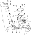
- FIG. 1A and 1B are perspective views showing before and after operation of a first embodiment of a limit switch according to an embodiment of the present invention. It is a disassembled perspective view of the limit switch shown in FIG.
- FIG. 2 is an exploded perspective view of the limit switch shown in FIG. 1 viewed from a different angle.
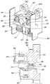
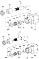
- 4A and 4B are an enlarged perspective view and a longitudinal sectional view of the switch body shown in FIG. 5A is a partially exploded perspective view of the drive mechanism unit shown in FIG. 2, and FIG. 5B is a partially exploded perspective view of the drive mechanism unit according to the second embodiment.
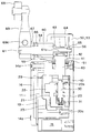
- 6A and 6B are front views for explaining a method of connecting lead wires to the limit switch shown in FIG. 7A is a front view following FIG. 6B, and FIG. 7B is a front view for explaining another connection method. It is a center longitudinal cross-sectional view before operation
- the limit switch according to the first embodiment drives the switch body 20 incorporated in the housing 10 through a plunger 40 by a drive mechanism unit 50 having an operation lever 69. is there.
- the housing 10 has a box shape capable of accommodating a switch body 20 described later, and an annular rib 12 is formed along an opening 11 provided on the front surface thereof. Then, the opening 11 is sealed by positioning the annular seal member 13 on the annular rib 12 and fixing the cover 14 to the housing 10 with a fixing screw 14a.
- the housing 10 has a connection hole 15 on the bottom surface and an operation hole 16 on the ceiling surface. Positioning slits 17 are formed on the inner peripheral surface of the operation hole 16 in the axial direction at a pitch of 90 degrees, and an annular step 18 is formed concentrically near the opening edge of the operation hole 16. Has been.
- the switch body 20 has an outer shape that can be accommodated from the opening 11 of the housing 10, and is fixed to the inner surface of the housing 10 with three fixing screws 20 a. Further, as shown in FIG. 4, the switch body 20 is divided into two upper and lower stages with partitioning ribs 21 and a hexagonal first protrusion 22 that protrudes in the center of the upper stage is provided. A square second protrusion 23 is provided at the center of the lower stage. Further, fixed contact terminals 25 and 26 having a substantially U-shaped cross section provided with connection screws 24 are embedded on both sides of the first projection 22, while connection screws 24 are provided on both sides of the second projection. Fixed contact terminals 27 and 28 are embedded. The switch body 20 is provided such that the insulating walls 29 and 29 protrude toward the front side from both side edge portions.
- the switch body 20 supports an operation shaft 30 so as to be slidable up and down and is biased upward via a coil spring 31. For this reason, the upper end portion of the operation shaft 30 protrudes from an operation hole 20 b provided in the ceiling surface of the switch body 20. Then, the operation shaft 30 reverses the movable contact piece 32 shown in FIG. 4 up and down, so that the movable contacts 33 provided at both ends of the movable contact piece 32 become fixed contacts of the fixed contact terminals 25 and 26.
- the fixed contact terminals 27 and 28 are alternately contacted and separated from the fixed contacts.
- the plunger 40 has an outer shape that can move up and down along the operation hole 16 of the housing 10, and a substantially T-shaped operating protrusion on the upper surface of the flange portion 41.
- a guide rib 43 is provided on the lower surface base of the flange 41. Then, by selecting and fitting the guide rib 43 of the plunger 40 into any one of the positioning slits 17 provided in the housing 10, the lower end portion of the plunger 40 becomes the upper end portion of the operation shaft 30. The rotation direction of the operation lever 69 described later can be detected.
- the drive mechanism 50 is assembled to a box 53 fixed to the upper surface of the housing 10 via a seal ring 51 with a fixing screw 52. That is, as shown in FIG. 8, a rotating shaft 61 is rotatably inserted into a cylindrical bearing portion 60 press-fitted and fixed from an assembly hole 55 of a cylindrical rib 54 provided in the box 53. The distal end of the rotating shaft 61 is fitted in a bearing recess 56 provided on the inner surface of the box 53, and a return coil spring 62 is sandwiched between the distal ends of the rotating shaft 61. A pair of annular cams 63 and 64 are prevented from coming off via the E-ring 65 (for convenience of explanation, the return coil spring 62 is not shown in FIGS. 8 and 9).
- the annular cams 63 and 64 have through holes 63a and 64a that can be fitted to the tip of the rotating shaft 61 provided with a flat surface 61a (FIG. 3). . Further, on the inner peripheral surfaces of the through holes 63a and 64a, protrusions 63b and 64b having a triangular section that can be locked to the edge of the flat surface 61a of the rotating shaft 61 are provided along the axial direction. It is. Further, both ends of the return coil spring 62 are engaged with the annular cams 63 and 64, respectively, so that a biasing force in a rotating direction is applied to the rotating shaft 61. This is for returning an operation lever 69 described later to the original position.
- a rubber oil seal 66 is mounted on the rear end side of the rotating shaft 61 protruding from the cylindrical rib 54, and a set position display plate 67 is engaged. It is. Further, an operating lever 69 having a roller 68 is fixed to the rear end portion of the rotating shaft 61 via an adjusting screw 69a.
- the annular cams 63 and 64 are not only fixed through the E-ring 65 but also, for example, a stopper 65a that is press-fitted and fixed to the tip of the rotating shaft 61 as in the second embodiment shown in FIG. 5B.
- the annular cams 63 and 64 may be prevented from coming off.
- Others are the same as those in the first embodiment described above, and thus the same parts are denoted by the same reference numerals and description thereof is omitted.
- the switch body 20 is inserted from the opening 11 of the housing 10 and fixed with three fixing screws 20a.
- the guide ribs 43 of the plunger 40 are selectively fitted and assembled to the positioning slits 17 provided in the operation hole 16 of the housing 10.
- a seal ring 51 is fitted into an annular step 18 provided around the operation hole 16, and the box 53 is fixed to the housing 10 with a fixing screw 52.
- annular cam 63, a return coil spring 62 and an annular cam 64 are sequentially inserted into the distal end side of the rotating shaft 61 and are prevented from coming off by an E-ring 65.
- the cylindrical bearing portion 60 is press-fitted and fixed in the assembly hole 55. As a result, the cylindrical bearing portion 60 comes into contact with the outward surface of the annular cam 63 and the rotating shaft 61 is prevented from coming off.
- annular cams 63 and 64 are in contact with the operating protrusion 42 of the plunger 40. Further, a rubber oil seal 66 is fitted to the rear end side of the rotation shaft 61 protruding from the box 53 to seal and engage the set position display plate 67. Next, an operation lever 69 is assembled to the rear end of the rotating shaft 61 and fixed with an adjusting screw 69a.
- the lead wires 70 and 71 are connected to the lower fixed contact terminals 27 and 28 as shown in FIG. 6A. Each terminal is fixed with a connection screw 24.
- the connection terminal of the lead wire 72 is fixed to the fixed contact terminal 26 with the connection screw 24.
- the connection work is completed by fixing the lead wire 73 to the fixed contact terminal 25 with the connection screw 24.
- the creeping distance is increased by the partition rib 21 and the first protrusion 22 and the second protrusion 23 function as insulating walls, so that a limit switch having excellent insulating characteristics can be obtained.
- the lead wire 72 is bent along the first protrusion 22 to be connected to the fixed contact terminal 25, and the lead wire 73 is The detour along the one protrusion 22 may be connected to the fixed contact terminal 26.
- the outer peripheral surface of the first protrusion 22 is shaped along the wiring path of the lead wires 72 and 73 (such as a substantially hexagon or a substantially parallelogram when the first protrusion 22 is viewed from the front.
- an external force in the clockwise direction is detected by engaging the guide rib 43 with the selected positioning slit 17, but in the counterclockwise direction. It can be used to detect no external force.
- the operation lever is not necessarily assembled vertically, and may be attached, for example, in a horizontal direction or an oblique direction.
- the present invention is not necessarily limited thereto, and may be applied to, for example, a limit switch that connects six or eight lead wires.
- a single annular cam may be attached to the pivot shaft.
- the present invention is not limited to the limit switch described above, and may be applied to limit switches of other shapes.
Landscapes
- Physics & Mathematics (AREA)
- Electromagnetism (AREA)
- Rotary Switch, Piano Key Switch, And Lever Switch (AREA)
- Push-Button Switches (AREA)
- Switch Cases, Indication, And Locking (AREA)
Abstract
リード線の接続作業が容易で、作業効率の良いリミットスイッチを提供する。このため、正面に開口部(11)を有するハウジング(10)内にスイッチ本体(20)を固定するとともに、前記ハウジング(10)の底面にリード線(70~73)を引き込む接続孔を有する一方、前記スイッチ本体(20)の正面を上下に複数段に仕切るとともに、各段に一対の固定接点端子(25,26,27,28)を埋設し、前記スイッチ本体(20)の天井面から露出する操作軸(30)を軸心方向に駆動して接点を開閉するリミットスイッチである。特に、前記スイッチ本体(20)の正面の各段に埋設した固定接点端子(25,26)および固定接点端子(27,28)の間に、第1突部(22)および第2突部(23)をそれぞれ突設した。
Description
本発明はリミットスイッチ、特に、リミットスイッチの固定接点端子に接続するリード線の配線構造に関する
従来、リミットスイッチの固定接点端子にリード線を接続する場合には、特許文献1の図3に示すように、基台1の底面に設けた図示されていない接続孔から4本のリード線を引き込み、その先端に設けた圧着端子を、上下2段にそれぞれ設けた一対の固定接点端子に接続ネジで固定していた。
しかしながら、前述のリミットスイッチでは、下段の一対の固定接点端子にリード線を接続する作業は比較的、容易であるが、上段の一対の固定接点端子にリード線を接続しようとすると、リード線の取り回しに手間がかかる。特に、リード線が太く、作業空間が狭い場合に、引き込み位置と異なる位置の固定接点端子にリード線を接続しようとすると、リード線を複雑に折り曲げて調整する必要があり、作業効率が悪いという問題点がある。
本発明に係るリミットスイッチは、前述の問題点に鑑み、リード線の接続作業が容易で、作業効率の良いリミットスイッチを提供することを課題とする。
本発明に係るリミットスイッチは、前述の問題点に鑑み、リード線の接続作業が容易で、作業効率の良いリミットスイッチを提供することを課題とする。
本発明に係るリミットスイッチは、正面に開口部を有するハウジング内にスイッチ本体を固定するとともに、前記ハウジングの底面にリード線を引き込む接続孔を有する一方、前記スイッチ本体の正面を上下に複数段に仕切るとともに、各段に一対の固定接点端子を埋設し、前記スイッチ本体の天井面から露出する操作軸を軸心方向に駆動して接点を開閉するリミットスイッチであって、前記スイッチ本体の正面の各段に埋設した固定接点端子の間に、突部を突設した構成としてある。
本発明によれば、前記突部を介してリード線を引き回して配線できるので、接続作業が容易になり、作業効率が向上する。また、隣り合う固定接点端子が前記突部で仕切られるので、優れた絶縁特性を有するリミットスイッチが得られる。
本発明の実施形態としては、前記突部の外周面が前記リード線の配線経路に沿った形状を有していてもよい。
本実施形態によれば、リード線の接続作業をより一層効率化できる。
本実施形態によれば、リード線の接続作業をより一層効率化できる。
本発明の他の実施形態としては、上段に位置する固定接点端子を、下段に位置する固定接点端子よりも手前側に迫り出すように配置してもよい。
本実施形態によれば、上下の固定接点端子に段差が生じるので、下段側の固定接点端子にリード線を接続しておいても、上段側の固定接点端子の接続作業の邪魔にならず、接続作業の効率がより一層向上する。
本実施形態によれば、上下の固定接点端子に段差が生じるので、下段側の固定接点端子にリード線を接続しておいても、上段側の固定接点端子の接続作業の邪魔にならず、接続作業の効率がより一層向上する。
本発明の別の実施形態としては、スイッチ本体の両側側面のうち、少なくとも片側縁部から手前側に突出する絶縁壁を設けてもよい。
本実施形態によれば、前記絶縁壁が、リード線がハウジングの内側面に直接当接することを防止できるので、絶縁特性がより一層向上する。
本実施形態によれば、前記絶縁壁が、リード線がハウジングの内側面に直接当接することを防止できるので、絶縁特性がより一層向上する。
本発明の異なる実施形態としては、固定接点端子に、先端に圧着端子を設けたリード線を接続ネジで接続してもよい。
本実施形態によれば、固定接点端子に圧着端子を介してリード線を接続できるので、接続作業がより一層容易になり、作業効率を改善できるという効果がある。
本実施形態によれば、固定接点端子に圧着端子を介してリード線を接続できるので、接続作業がより一層容易になり、作業効率を改善できるという効果がある。
本発明に係るリミットスイッチの実施形態を図1ないし図9に従って説明する。
第1実施形態に係るリミットスイッチは、図1ないし3に示すように、ハウジング10内に組み込んだスイッチ本体20を、プランジャ40を介し、操作レバー69を備えた駆動機構部50で駆動するものである。
第1実施形態に係るリミットスイッチは、図1ないし3に示すように、ハウジング10内に組み込んだスイッチ本体20を、プランジャ40を介し、操作レバー69を備えた駆動機構部50で駆動するものである。
前記ハウジング10は、後述するスイッチ本体20を収納可能な箱形状を有するものであり、その正面に設けた開口部11に沿って環状リブ12が形成されている。そして、前記環状リブ12に環状シール材13を位置決めし、前記ハウジング10にカバー14を固定ネジ14aでネジ止め固定することにより、前記開口部11が密閉される。また、前記ハウジング10は、その底面に接続孔15を設けてあるとともに、その天井面に操作孔16を設けてある。そして、前記操作孔16の内周面には位置決め用スリット17が90度ピッチで軸心方向に形成されているとともに、前記操作孔16の開口縁部近傍に環状段部18が同心円上に形成されている。
スイッチ本体20は、前記ハウジング10の前記開口部11から収納可能な外形形状を有し、前記ハウジング10の内側面に3個の固定ネジ20aで固定される。
また、前記スイッチ本体20は、図4に示すように、その正面が仕切り用リブ21で上下2段に仕切られ、その上段中央に傾斜した6角形の第1突部22が突設される一方、その下段中央に方形の第2突部23が突設されている。さらに、前記第1突部22の両側には接続ネジ24を備えた断面略コ字形状の固定接点端子25,26が埋設されている一方、第2突部の両側には接続ネジ24を備えた固定接点端子27,28が埋設されている。
そして、前記スイッチ本体20は、その両側縁部から絶縁壁29,29が手前側に迫り出すように設けられている。
また、前記スイッチ本体20は、図4に示すように、その正面が仕切り用リブ21で上下2段に仕切られ、その上段中央に傾斜した6角形の第1突部22が突設される一方、その下段中央に方形の第2突部23が突設されている。さらに、前記第1突部22の両側には接続ネジ24を備えた断面略コ字形状の固定接点端子25,26が埋設されている一方、第2突部の両側には接続ネジ24を備えた固定接点端子27,28が埋設されている。
そして、前記スイッチ本体20は、その両側縁部から絶縁壁29,29が手前側に迫り出すように設けられている。
さらに、前記スイッチ本体20は、図8および図9に示すように、その内部に操作軸30を上下にスライド移動可能に支持してあるとともに、コイルバネ31を介して上方に付勢してある。このため、前記操作軸30の上端部が前記スイッチ本体20の天井面に設けた操作孔20bから突出している。そして、前記操作軸30は、図4に示す可動接触片32を上下に反転させることにより、前記可動接触片32の両端に設けた可動接点33が、前記固定接点端子25,26の固定接点と、前記固定接点端子27,28の固定接点とに交互に接離する。
プランジャ40は、図2および図3に示すように、前記ハウジング10の操作孔16に沿って上下動可能な外形形状を有し、その鍔部41の上面に略T字形状の操作用突条42を設ける一方、前記鍔部41の下面基部にガイド用リブ43を設けてある。そして、前記ハウジング10に設けた位置決め用スリット17のいずれかに、前記プランジャ40のガイド用リブ43を選択して嵌合することにより、前記プランジャ40の下端部が前記操作軸30の上端部に当接し、後述する操作レバー69の回動方向を検出できる。
駆動機構部50は、図2に示すように、前記ハウジング10の上面にシールリング51を介して固定ネジ52で固定されたボックス53に組み付けられている。
すなわち、図8に示すように、前記ボックス53に設けた筒状リブ54の組付孔55から圧入固定された円筒状軸受部60に回動軸61が回動可能に挿入されている。そして、前記回動軸61の先端部が前記ボックス53の内側面に設けた軸受け用凹部56に嵌合されているとともに、前記回動軸61の先端側には復帰用コイルバネ62を狭持する一対の環状カム63,64がEリング65を介して抜け止めされている(なお、説明の便宜上、図8,9において復帰用コイルバネ62は図示されていない)。
すなわち、図8に示すように、前記ボックス53に設けた筒状リブ54の組付孔55から圧入固定された円筒状軸受部60に回動軸61が回動可能に挿入されている。そして、前記回動軸61の先端部が前記ボックス53の内側面に設けた軸受け用凹部56に嵌合されているとともに、前記回動軸61の先端側には復帰用コイルバネ62を狭持する一対の環状カム63,64がEリング65を介して抜け止めされている(なお、説明の便宜上、図8,9において復帰用コイルバネ62は図示されていない)。
特に、前記環状カム63,64は、図5Aに示すように、平坦面61a(図3)を設けた前記回動軸61の先端部に嵌合可能な貫通孔63a,64aを有している。そして、前記貫通孔63a,64aの内周面には、前記回動軸61の平坦面61aの縁部に係止可能な断面3角形の突条63b,64bを軸心方向に沿って突設してある。また、前記復帰用コイルバネ62は、その両端が前記環状カム63,64にそれぞれ係止することにより、前記回動軸61に回動方向の付勢力を付与する。後述する操作レバー69を元の位置に復帰させるためである。
一方、図2に示すように、前記筒状リブ54から突出する前記回動軸61の後端側にはゴム製のオイルシール66が装着されているとともに、セット位置表示板67を係合してある。さらに、前記回動軸61の後端部にはローラ68を備えた操作レバー69が調整ネジ69aを介して固定されている。
なお、前記環状カム63,64は、Eリング65を介して固定するだけでなく、例えば、図5Bに示す第2実施形態のように、回動軸61の先端部に圧入固定したストッパ65aで前記環状カム63,64の抜け止めを行ってもよい。他は前述の第1実施形態と同様であるので、同一部分に同一番号を附して説明を省略する。
次に、前述の構成部材からなるリミットスイッチの組立方法について説明する。
ハウジング10の開口部11からスイッチ本体20を挿入し、3個の固定ネジ20aで固定する。一方、前記ハウジング10の操作孔16に設けた位置決め用スリット17にプランジャ40のガイド用リブ43を選択的に嵌合して組み付ける。そして、前記操作孔16の周囲に設けた環状段部18にシールリング51を嵌合し、前記ハウジング10にボックス53を固定ネジ52で固定する。
ハウジング10の開口部11からスイッチ本体20を挿入し、3個の固定ネジ20aで固定する。一方、前記ハウジング10の操作孔16に設けた位置決め用スリット17にプランジャ40のガイド用リブ43を選択的に嵌合して組み付ける。そして、前記操作孔16の周囲に設けた環状段部18にシールリング51を嵌合し、前記ハウジング10にボックス53を固定ネジ52で固定する。
一方、回動軸61の先端側に環状カム63、復帰用コイルバネ62および環状カム64を順次挿入するとともに、Eリング65で抜け止めする。そして、前記ボックス53の組付孔55から前記回動軸61を挿入し、前記回動軸61の先端部をボックス53の内側面に設けた軸受け凹部56(図8)に嵌合した後、円筒状軸受部60を組付孔55に圧入固定する。これにより、前記円筒状軸受部60が環状カム63の外向面に当接し、回動軸61が抜け止めされる。このとき、環状カム63,64がプランジャ40の操作用突条42に当接している。さらに、前記ボックス53から突出する回動軸61の後端側にゴム製のオイルシール66を嵌合することにより、シールするとともに、セット位置表示板67を係合する。ついで、前記回動軸61の後端部に操作レバー69を組み付け、調整ネジ69aで固定する。
そして、前記環状リブ12に環状シール材13を位置決めした後、ハウジング10にカバー14を固定ネジ14aでネジ止めすることにより、組立作業が完了する。
ついで、現場において前記スイッチ本体20にリード線を接続する場合には、前記カバー14を取り外した後、図6Aに示すように、下段側の固定接点端子27,28にリード線70,71の接続端子をそれぞれ接続ネジ24で固定する。ついで、図6Bに示すように、固定接点端子26にリード線72の接続端子を接続ネジ24で固定する。最後に、リード線73を固定接点端子25に接続ネジ24で固定することにより、接続作業が完了する。
本実施形態によれば、仕切り用リブ21によって沿面距離が長くなるとともに、第1突部22および第2突部23が絶縁壁として機能するので、絶縁特性に優れたリミットスイッチが得られる。
また、前述の接続構造と異なる接続を行う場合には、図7Bに示すように、リード線72を第1突部22に沿って折り曲げて固定接点端子25に接続するとともに、リード線73を第1突部22に沿って迂回させて固定接点端子26に接続してもよい。
本実施形態によれば、第1突部22の外周面がリード線72,73の配線経路に沿った形状(第1突部22を正面から見て、略六角形や略平行四辺形などのように、各々略平行な少なくとも2対の線分が、垂直とは異なる角度で結合された領域を含む形状)を有しているので、接続作業を効率化できるという利点がある。
本実施形態によれば、第1突部22の外周面がリード線72,73の配線経路に沿った形状(第1突部22を正面から見て、略六角形や略平行四辺形などのように、各々略平行な少なくとも2対の線分が、垂直とは異なる角度で結合された領域を含む形状)を有しているので、接続作業を効率化できるという利点がある。
次に、本実施形態に係るリミットスイッチの動作を説明する。
すなわち、図8および図9に示すように、操作レバー69に外力が負荷されていない場合には、操作レバー69が垂直に立設し、一対のカム部材63,64がプランジャ40の操作用突条42に当接しているだけであり、プランジャ40を押し下げていない。このため、コイルバネ31のバネ力で操作軸30が上方に押し上げられ、可動接触片32の可動接点33が固定接点端子25,26に接触している。
すなわち、図8および図9に示すように、操作レバー69に外力が負荷されていない場合には、操作レバー69が垂直に立設し、一対のカム部材63,64がプランジャ40の操作用突条42に当接しているだけであり、プランジャ40を押し下げていない。このため、コイルバネ31のバネ力で操作軸30が上方に押し上げられ、可動接触片32の可動接点33が固定接点端子25,26に接触している。
そして、前記操作レバー69が外力で時計回り方向に回動すると、回動軸61に設けた平坦面61aの一方側縁部が環状カム63の突条63aに係止する。このため、前記環状カム63だけが回転し、プランジャ40の操作用突条42を押し下げることにより、操作軸30が押し下げられる。この結果、可動接触片32が押し下げられ、反転することにより、可動接点33が固定接点端子25,26から固定接点端子27,28に切り替わる。
ついで、外部からの負荷が解除されると、復帰用コイルバネ62のバネ力で回動軸61が逆方向に回動し、操作レバー69が元の位置に復帰するとともに、コイルバネ31のバネ力で操作軸30,プランジャ40が押し上げられる。
ついで、外部からの負荷が解除されると、復帰用コイルバネ62のバネ力で回動軸61が逆方向に回動し、操作レバー69が元の位置に復帰するとともに、コイルバネ31のバネ力で操作軸30,プランジャ40が押し上げられる。
一方、前記操作レバー69が外力で反時計回り方向に回動すると、回動軸61に設けた平坦面61aの他方側縁部が環状カム64の突条64aに係止する。このため、前記環状カム64だけが回転し、プランジャ40の操作用突条42を押し下げることにより、操作軸30が押し下げられる。この結果、可動接触片32が押し下げられ、反転することにより、可動接点33が固定接点端子25,26から固定接点端子27,28に切り替わる。
ついで、外部からの負荷が解除されると、復帰用コイルバネ62のバネ力で回動軸61が逆方向に回動し、操作レバー69が元の位置に復帰するとともに、コイルバネ31のバネ力で操作軸30,プランジャ40が押し上げられる。
ついで、外部からの負荷が解除されると、復帰用コイルバネ62のバネ力で回動軸61が逆方向に回動し、操作レバー69が元の位置に復帰するとともに、コイルバネ31のバネ力で操作軸30,プランジャ40が押し上げられる。
本実施形態では、プランジャ40をハウジング10に組み付ける際に、ガイド用リブ43を選択した位置決め用スリット17に係合することにより、例えば、時計回り方向の外力は検出するが、半時計回り方向の外力は検出しないという使用が可能である。
また、操作レバーは必ずしも垂直に組み付ける必要はなく、例えば、水平方向あるいは斜め方向に取り付けても良い。
さらに、前述の実施形態では4本のリード線を接続する場合について説明したが、必ずしもこれに限らず、例えば、6本あるいは8本のリード線を接続するリミットスイッチに適用してもよい。
そして、前記回動軸には1個の環状カムを取り付けてもよいことは勿論である。
さらに、前述の実施形態では4本のリード線を接続する場合について説明したが、必ずしもこれに限らず、例えば、6本あるいは8本のリード線を接続するリミットスイッチに適用してもよい。
そして、前記回動軸には1個の環状カムを取り付けてもよいことは勿論である。
本実施形態では、前述のリミットスイッチに限らず、他の形状のリミットスイッチに適用してもよいことは勿論である。
10:ハウジング
11:開口部
14:カバー
15:接続孔
16:操作孔
20:スイッチ本体
21:仕切り用リブ
22:第1突部
23:第2突部
24:接続ネジ
25,26,27,28:固定接点端子
29:絶縁壁
30:操作軸
31:コイルバネ
40:プランジャ
41:鍔部
42:操作用突条
43:ガイド用リブ
50:駆動機構部
51:シールリング
52:固定ネジ
53:ボックス
54:筒状リブ
55:組付孔
56:軸受け用凹部
60:円筒状軸受部
61:回動軸
61a:平坦面
62:復帰用コイルバネ
63,64:環状カム
65:Eリング
65a:ストッパ
66:オイルシール
67:セット位置表示板
68:ローラ
69:操作レバー
70,71,72,73:リード線
11:開口部
14:カバー
15:接続孔
16:操作孔
20:スイッチ本体
21:仕切り用リブ
22:第1突部
23:第2突部
24:接続ネジ
25,26,27,28:固定接点端子
29:絶縁壁
30:操作軸
31:コイルバネ
40:プランジャ
41:鍔部
42:操作用突条
43:ガイド用リブ
50:駆動機構部
51:シールリング
52:固定ネジ
53:ボックス
54:筒状リブ
55:組付孔
56:軸受け用凹部
60:円筒状軸受部
61:回動軸
61a:平坦面
62:復帰用コイルバネ
63,64:環状カム
65:Eリング
65a:ストッパ
66:オイルシール
67:セット位置表示板
68:ローラ
69:操作レバー
70,71,72,73:リード線
Claims (5)
- 正面に開口部を有するハウジング内にスイッチ本体を固定するとともに、前記ハウジングの底面にリード線を引き込む接続孔を有する一方、前記スイッチ本体の正面を上下に複数段に仕切るとともに、各段に一対の固定接点端子を埋設し、前記スイッチ本体の天井面から露出する操作軸を軸心方向に駆動して接点を開閉するリミットスイッチであって、
前記スイッチ本体の正面の各段に埋設した固定接点端子の間に、突部を突設したことを特徴とするリミットスイッチ。 - 前記突部の外周面が前記リード線の配線経路に沿った形状を有していることを特徴とする請求項1に記載のリミットスイッチ。
- 上段に位置する固定接点端子を、下段に位置する固定接点端子よりも手前側に迫り出すように配置したことを特徴とする請求項1または2に記載のリミットスイッチ。
- スイッチ本体の両側側面のうち、少なくとも片側縁部から手前側に突出する絶縁壁を設けたことを特徴とする請求項1ないし3いずれか1項に記載のリミットスイッチ。
- 固定接点端子に、先端に圧着端子を設けたリード線を接続ネジで接続したことを特徴とする請求項1ないし4のいずれか1項に記載のリミットスイッチ。
Priority Applications (4)
| Application Number | Priority Date | Filing Date | Title |
|---|---|---|---|
| CN201280064455.9A CN104011820B (zh) | 2012-01-13 | 2012-03-14 | 限位开关 |
| ES12864762.5T ES2674151T3 (es) | 2012-01-13 | 2012-03-14 | Interruptor de fin de carrera |
| EP12864762.5A EP2804192B1 (en) | 2012-01-13 | 2012-03-14 | Limit switch |
| US14/368,814 US9490081B2 (en) | 2012-01-13 | 2012-03-14 | Limit switch |
Applications Claiming Priority (2)
| Application Number | Priority Date | Filing Date | Title |
|---|---|---|---|
| JP2012005437A JP6080359B2 (ja) | 2012-01-13 | 2012-01-13 | リミットスイッチ |
| JP2012-005437 | 2012-01-13 |
Publications (1)
| Publication Number | Publication Date |
|---|---|
| WO2013105276A1 true WO2013105276A1 (ja) | 2013-07-18 |
Family
ID=48781246
Family Applications (1)
| Application Number | Title | Priority Date | Filing Date |
|---|---|---|---|
| PCT/JP2012/056494 Ceased WO2013105276A1 (ja) | 2012-01-13 | 2012-03-14 | リミットスイッチ |
Country Status (6)
| Country | Link |
|---|---|
| US (1) | US9490081B2 (ja) |
| EP (1) | EP2804192B1 (ja) |
| JP (1) | JP6080359B2 (ja) |
| CN (1) | CN104011820B (ja) |
| ES (1) | ES2674151T3 (ja) |
| WO (1) | WO2013105276A1 (ja) |
Cited By (1)
| Publication number | Priority date | Publication date | Assignee | Title |
|---|---|---|---|---|
| EP2863405A1 (en) * | 2013-10-15 | 2015-04-22 | Omron Corporation | Limit switch |
Families Citing this family (14)
| Publication number | Priority date | Publication date | Assignee | Title |
|---|---|---|---|---|
| JP6080359B2 (ja) * | 2012-01-13 | 2017-02-15 | オムロン株式会社 | リミットスイッチ |
| JP6277668B2 (ja) * | 2013-02-14 | 2018-02-14 | オムロン株式会社 | 操作レバーのシール構造およびこれを用いた電動工具 |
| USD751997S1 (en) | 2013-08-08 | 2016-03-22 | Omron Corporation | Box cover for limit switch |
| JP2015082489A (ja) * | 2013-10-24 | 2015-04-27 | オムロン株式会社 | スイッチ |
| US9928972B1 (en) * | 2016-11-09 | 2018-03-27 | Honeywell International Inc. | Limit switch housing with reset function |
| CN108400031B (zh) * | 2017-02-06 | 2021-12-21 | 霍尼韦尔国际公司 | 限位开关复位键 |
| DE102018127261B4 (de) * | 2017-11-23 | 2024-01-04 | Defond Components Limited | Elektrische Schaltereinheit mit einem Dichtungselement zur Verwendung bei einer elektrischen Vorrichtung |
| JP6866864B2 (ja) * | 2018-03-14 | 2021-04-28 | オムロン株式会社 | リミットスイッチ |
| JP6866863B2 (ja) * | 2018-03-14 | 2021-04-28 | オムロン株式会社 | リミットスイッチ |
| JP6866862B2 (ja) * | 2018-03-14 | 2021-04-28 | オムロン株式会社 | リミットスイッチ |
| JP6580192B1 (ja) * | 2018-04-23 | 2019-09-25 | トーヨーカネツソリューションズ株式会社 | 搬送装置の遮断機構 |
| JP7467788B2 (ja) * | 2018-04-23 | 2024-04-16 | トーヨーカネツ株式会社 | 搬送装置の遮断機構 |
| CN108766803B (zh) * | 2018-08-02 | 2024-10-11 | 上海飞力勋铖电气科技有限公司 | 一种模块化结构的防水行程开关 |
| CN114068207B (zh) * | 2021-12-16 | 2024-06-14 | 深圳市海本电子科技有限公司 | 一种电子元器件及其制造方法 |
Citations (6)
| Publication number | Priority date | Publication date | Assignee | Title |
|---|---|---|---|---|
| JPS5340870A (en) * | 1976-09-27 | 1978-04-13 | Matsushita Electric Works Ltd | Electric switch |
| JPS5346572U (ja) * | 1976-09-27 | 1978-04-20 | ||
| JPS6319717U (ja) * | 1986-07-18 | 1988-02-09 | ||
| JPH02278624A (ja) * | 1989-04-20 | 1990-11-14 | Omron Corp | スイッチ |
| JP2001043774A (ja) | 1999-07-30 | 2001-02-16 | Matsushita Electric Works Ltd | 接点開閉装置 |
| JP2009211898A (ja) * | 2008-03-04 | 2009-09-17 | Omron Corp | 端子台構造とこれを備えたスイッチ |
Family Cites Families (8)
| Publication number | Priority date | Publication date | Assignee | Title |
|---|---|---|---|---|
| DE3201169C2 (de) * | 1982-01-16 | 1984-06-28 | Danfoss A/S, Nordborg | Vorrichtung zum Festklemmen elektrischer Leiter insbesondere von Drähten |
| JPH0727063U (ja) * | 1993-10-15 | 1995-05-19 | ケル株式会社 | 端子台 |
| FR2820542B1 (fr) * | 2001-02-07 | 2004-07-16 | Schneider Electric Ind Sa | Interrupteur de position |
| JP3785942B2 (ja) * | 2001-03-30 | 2006-06-14 | 松下電工株式会社 | 接続変換装置 |
| CN201904233U (zh) * | 2010-12-21 | 2011-07-20 | 天津市六开电梯配套有限责任公司 | 安全触点型限位开关 |
| JP6080359B2 (ja) * | 2012-01-13 | 2017-02-15 | オムロン株式会社 | リミットスイッチ |
| JP5935334B2 (ja) * | 2012-01-13 | 2016-06-15 | オムロン株式会社 | リミットスイッチ |
| JP5870704B2 (ja) * | 2012-01-13 | 2016-03-01 | オムロン株式会社 | リミットスイッチ、およびその製造方法 |
-
2012
- 2012-01-13 JP JP2012005437A patent/JP6080359B2/ja active Active
- 2012-03-14 EP EP12864762.5A patent/EP2804192B1/en active Active
- 2012-03-14 US US14/368,814 patent/US9490081B2/en active Active
- 2012-03-14 CN CN201280064455.9A patent/CN104011820B/zh active Active
- 2012-03-14 WO PCT/JP2012/056494 patent/WO2013105276A1/ja not_active Ceased
- 2012-03-14 ES ES12864762.5T patent/ES2674151T3/es active Active
Patent Citations (6)
| Publication number | Priority date | Publication date | Assignee | Title |
|---|---|---|---|---|
| JPS5340870A (en) * | 1976-09-27 | 1978-04-13 | Matsushita Electric Works Ltd | Electric switch |
| JPS5346572U (ja) * | 1976-09-27 | 1978-04-20 | ||
| JPS6319717U (ja) * | 1986-07-18 | 1988-02-09 | ||
| JPH02278624A (ja) * | 1989-04-20 | 1990-11-14 | Omron Corp | スイッチ |
| JP2001043774A (ja) | 1999-07-30 | 2001-02-16 | Matsushita Electric Works Ltd | 接点開閉装置 |
| JP2009211898A (ja) * | 2008-03-04 | 2009-09-17 | Omron Corp | 端子台構造とこれを備えたスイッチ |
Cited By (2)
| Publication number | Priority date | Publication date | Assignee | Title |
|---|---|---|---|---|
| EP2863405A1 (en) * | 2013-10-15 | 2015-04-22 | Omron Corporation | Limit switch |
| CN104576110A (zh) * | 2013-10-15 | 2015-04-29 | 欧姆龙株式会社 | 开关 |
Also Published As
| Publication number | Publication date |
|---|---|
| CN104011820A (zh) | 2014-08-27 |
| US20140326586A1 (en) | 2014-11-06 |
| EP2804192A4 (en) | 2015-09-30 |
| US9490081B2 (en) | 2016-11-08 |
| EP2804192B1 (en) | 2018-05-09 |
| CN104011820B (zh) | 2016-10-12 |
| EP2804192A1 (en) | 2014-11-19 |
| ES2674151T3 (es) | 2018-06-27 |
| JP2013145675A (ja) | 2013-07-25 |
| JP6080359B2 (ja) | 2017-02-15 |
Similar Documents
| Publication | Publication Date | Title |
|---|---|---|
| JP6080359B2 (ja) | リミットスイッチ | |
| JP2013145675A5 (ja) | ||
| JP5870704B2 (ja) | リミットスイッチ、およびその製造方法 | |
| JP5935334B2 (ja) | リミットスイッチ | |
| JP2013145674A5 (ja) | ||
| JP2013145676A5 (ja) | ||
| KR101171963B1 (ko) | 직관형 led 램프용 스위치 장치 및 그것을 사용한 직관형 led 램프 | |
| US9853429B2 (en) | Modular push switch mechanism | |
| KR20120069585A (ko) | 직관형 led 램프용 스위치 장치 및 그것을 사용한 직관형 led 램프 | |
| US8809712B2 (en) | Switch case with partitioned passages | |
| JP6109563B2 (ja) | 多光軸光電センサ | |
| CN203706983U (zh) | 旋钮以及电子器件 | |
| JP5411803B2 (ja) | 光モジュール用コネクタ | |
| CN104733205B (zh) | 旋钮以及电子器件 | |
| JP6520395B2 (ja) | シーソー式スイッチ装置 | |
| JP5788724B2 (ja) | インパクト工具 | |
| JP6058389B2 (ja) | 多光軸光電センサ | |
| WO2019078019A1 (ja) | スイッチ取付構造 | |
| JP6507851B2 (ja) | シーソー式スイッチ装置 |
Legal Events
| Date | Code | Title | Description |
|---|---|---|---|
| 121 | Ep: the epo has been informed by wipo that ep was designated in this application |
Ref document number: 12864762 Country of ref document: EP Kind code of ref document: A1 |
|
| WWE | Wipo information: entry into national phase |
Ref document number: 2012864762 Country of ref document: EP |
|
| WWE | Wipo information: entry into national phase |
Ref document number: 14368814 Country of ref document: US |
|
| NENP | Non-entry into the national phase |
Ref country code: DE |