WO2013105316A1 - タービンハウジングのスクロール構造 - Google Patents
タービンハウジングのスクロール構造 Download PDFInfo
- Publication number
- WO2013105316A1 WO2013105316A1 PCT/JP2012/076173 JP2012076173W WO2013105316A1 WO 2013105316 A1 WO2013105316 A1 WO 2013105316A1 JP 2012076173 W JP2012076173 W JP 2012076173W WO 2013105316 A1 WO2013105316 A1 WO 2013105316A1
- Authority
- WO
- WIPO (PCT)
- Prior art keywords
- front side
- exhaust gas
- tongue portion
- rear side
- turbine housing
- Prior art date
- Legal status (The legal status is an assumption and is not a legal conclusion. Google has not performed a legal analysis and makes no representation as to the accuracy of the status listed.)
- Ceased
Links
Images


Classifications
-
- F—MECHANICAL ENGINEERING; LIGHTING; HEATING; WEAPONS; BLASTING
- F04—POSITIVE - DISPLACEMENT MACHINES FOR LIQUIDS; PUMPS FOR LIQUIDS OR ELASTIC FLUIDS
- F04D—NON-POSITIVE-DISPLACEMENT PUMPS
- F04D29/00—Details, component parts, or accessories
- F04D29/40—Casings; Connections of working fluid
- F04D29/403—Casings; Connections of working fluid especially adapted for elastic fluid pumps
-
- F—MECHANICAL ENGINEERING; LIGHTING; HEATING; WEAPONS; BLASTING
- F01—MACHINES OR ENGINES IN GENERAL; ENGINE PLANTS IN GENERAL; STEAM ENGINES
- F01D—NON-POSITIVE DISPLACEMENT MACHINES OR ENGINES, e.g. STEAM TURBINES
- F01D9/00—Stators
- F01D9/02—Nozzles; Nozzle boxes; Stator blades; Guide conduits, e.g. individual nozzles
- F01D9/026—Scrolls for radial machines or engines
-
- F—MECHANICAL ENGINEERING; LIGHTING; HEATING; WEAPONS; BLASTING
- F02—COMBUSTION ENGINES; HOT-GAS OR COMBUSTION-PRODUCT ENGINE PLANTS
- F02C—GAS-TURBINE PLANTS; AIR INTAKES FOR JET-PROPULSION PLANTS; CONTROLLING FUEL SUPPLY IN AIR-BREATHING JET-PROPULSION PLANTS
- F02C6/00—Plural gas-turbine plants; Combinations of gas-turbine plants with other apparatus; Adaptations of gas-turbine plants for special use
- F02C6/04—Gas-turbine plants providing heated or pressurised working fluid for other apparatus, e.g. without mechanical power output
- F02C6/10—Gas-turbine plants providing heated or pressurised working fluid for other apparatus, e.g. without mechanical power output supplying working fluid to a user, e.g. a chemical process, which returns working fluid to a turbine of the plant
- F02C6/12—Turbochargers, i.e. plants for augmenting mechanical power output of internal-combustion piston engines by increase of charge pressure
-
- F—MECHANICAL ENGINEERING; LIGHTING; HEATING; WEAPONS; BLASTING
- F02—COMBUSTION ENGINES; HOT-GAS OR COMBUSTION-PRODUCT ENGINE PLANTS
- F02B—INTERNAL-COMBUSTION PISTON ENGINES; COMBUSTION ENGINES IN GENERAL
- F02B37/00—Engines characterised by provision of pumps driven at least for part of the time by exhaust
- F02B37/02—Gas passages between engine outlet and pump drive, e.g. reservoirs
- F02B37/025—Multiple scrolls or multiple gas passages guiding the gas to the pump drive
-
- F—MECHANICAL ENGINEERING; LIGHTING; HEATING; WEAPONS; BLASTING
- F05—INDEXING SCHEMES RELATING TO ENGINES OR PUMPS IN VARIOUS SUBCLASSES OF CLASSES F01-F04
- F05D—INDEXING SCHEME FOR ASPECTS RELATING TO NON-POSITIVE-DISPLACEMENT MACHINES OR ENGINES, GAS-TURBINES OR JET-PROPULSION PLANTS
- F05D2220/00—Application
- F05D2220/40—Application in turbochargers
Definitions
- the present invention relates to a scroll structure of a turbine housing, and more particularly, to a scroll structure of a turbine housing in a twin scroll turbocharger provided with two exhaust gas flow paths for guiding exhaust gas to a turbine rotor.
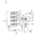
- FIG. 7 is a schematic view of an engine equipped with such a twin scroll turbocharger.
- the engine 1 provided with the twin scroll turbocharger 30 has, for example, four cylinders 10a, 10b, 10c and 10d, and the phase of the crank angle of these cylinders 10a to 10d is For example, it is assumed that they are shifted by 180 degrees.
- the cylinder 10 a and the cylinder 10 d are connected to the first exhaust manifold 16, and the cylinder 10 b and the cylinder 10 c are connected to the second exhaust manifold 18.
- the cylinders 10a and 10d are out of phase with each other by, for example, 360 degrees in crank angle so that the respective exhaust pulsations do not interfere with each other.
- the phase of the crank angle is, for example, 360 degrees out of phase, so that the respective exhaust pulsations do not interfere with each other.
- the first exhaust manifold 16 is connected to an exhaust gas flow path (front side flow path 22) formed in the turbine housing 32, whereby the exhaust gas discharged from the cylinders 10a and 10d is processed by the front side flow path 22. Is conducted to the turbine rotor 40 housed in the turbine housing 32 via the Similarly, the second exhaust manifold 18 is connected to the exhaust gas flow path (rear side flow path 24) formed in the turbine housing 32, whereby the exhaust gas discharged from the cylinders 10b and 10c is The flow is conducted to the turbine rotor 40 housed in the turbine housing 32 via the side flow passage 24.
- the turbine rotor 40 and the turbine shaft 36 that pivotally supports the turbine rotor 40 are rotated by the rotation of the moving blades 42 in response to the guided exhaust gas, and the compressor rotor 34 pivotally supported on the turbine shaft 36 is rotated.
- the compressed air is supplied to the cylinders 10a to 10d through the intake pipe 14 and the intake manifold 12. Further, the exhaust gas obtained by rotating the turbine rotor 40 is discharged from the exhaust pipe 20 to the outside of the engine 1.
- twin scroll turbocharger 30 it is necessary to design so that the flow capacities of the two exhaust gas channels 22, 24 are equal. That is, when there is a difference in the flow capacity of the front side flow passage 22 and the rear side flow passage 24, a pressure difference occurs in the exhaust gas flowing through the front side flow passage 22 and the rear side flow passage 24. It becomes the exhaust resistance difference of the exhaust gas discharged from the cylinders 10a, 10d and the cylinders 10b, 10c, and makes the operating states between the cylinders 10a, 10d and the cylinders 10b, 10c different. As a result, there is a possibility that the intake and exhaust characteristics of the engine 1 may be deteriorated. Therefore, in the twin scroll turbocharger 30, it is necessary to equalize the flow capacities of the front side flow passage 22 and the rear side flow passage 24.
- the turbine housing 32 in which the scroll portion 26 is generally inclined to the front side may be adopted.
- the scroll shaft 26 is inclined to the front side, and the central axis 28 'of the partition 28 that divides the front side flow passage 22 and the rear side flow passage 24 is on the front side with respect to the central axis 36' of the turbine shaft 36.
- the flow capacity of both exhaust gas flow passages can be obtained. There will be differences.
- the present invention is an invention made in view of such a problem of the prior art, and is a twin scroll turbocharger in which a partition dividing a scroll portion into two exhaust gas flow paths is inclined with respect to a central axis of a turbine shaft. It is an object of the present invention to provide a scroll structure of a turbine housing in which the flow capacities of the two exhaust gas flow paths are equally configured in the turbine housing.
- the scroll structure of the turbine housing of the present invention is
- the turbine rotor has a scroll portion for guiding exhaust gas, and the scroll portion has two exhaust gas flow paths, a front side flow path and a rear side flow path, which are partitioned by partitions in a cross sectional view perpendicular to the flow direction of the exhaust gas.
- the turbine housing of a twin scroll turbocharger wherein the partition wall is inclined with respect to the turbine shaft, the turbine housing has an outer periphery of the scroll portion in a longitudinal sectional view parallel to the flow direction of the exhaust gas.
- a tongue portion is formed to divide into a portion and an inner peripheral portion, and the tongue portion includes a front side tongue portion and a rear side tongue portion which close each of the two exhaust gas flow paths in the outer peripheral portion in a cross sectional view , In a cross-sectional view at the downstream end of the outer peripheral portion, the minimum outflow width portions of the inner side portions of the front side tongue portion and the rear side tongue portion, and the front side flow path and the rear side flow path, respectively. And are substantially parallel.
- the present invention is an invention relating to a turbine housing of a twin scroll turbocharger in which a partition that divides a scroll portion into two exhaust gas flow paths, a front side flow path and a rear side flow path, is inclined with respect to a turbine shaft.
- the tongue part which divides a scroll part into an outer peripheral part and an inner peripheral part is formed in the turbine housing of this invention in the longitudinal cross-sectional view parallel to the flow direction of waste gas.
- the tongue portion includes a front side tongue portion and a rear side tongue portion which respectively close the front side flow passage and the rear side flow passage in a cross sectional view perpendicular to the flow direction of the exhaust gas.
- the minimum outflow width of each of the inner side portions of the front side tongue portion and the rear side tongue portion and the front side flow path and the rear side flow path It is comprised so that a part may become substantially parallel.
- the inner side portions of the front side tongue portion and the rear side tongue portion are substantially parallel to the minimum outflow width portions of the front side flow passage and the rear side flow passage. Therefore, the flow rates of the exhaust gas flowing out of the front side flow passage and the rear side flow passage are approximately equal. That is, by aligning the inner side of the tongue parallel to the minimum outflow width in the exhaust gas flow path, the exhaust gas flowing along the inner side of the tongue at the outer periphery is the inner periphery beyond the tongue. It changes the flow in the direction perpendicular to the inner side and tries to flow to the moving blades in a flow perpendicular to the minimum outflow width.
- the flow velocity component of the exhaust gas that is perpendicular to the minimum outflow width portion becomes the exhaust gas flow rate that passes through the minimum outflow width portion (that is, flows through the exhaust gas flow path), so the front side tongue and rear side tongue
- the flow capacities of the two exhaust gas channels can be equalized.
- the respective inner side portions of the front side tongue portion and the rear side tongue portion and the respective minimum outflow width portions of the front side flow passage and the rear side flow passage are "substantially" parallel to each other.
- the angle between the inner side of each of the front side tongue and the rear side tongue and the minimum outflow width of each of the front side flow passage and the rear side flow passage is +10 degrees to -10 degrees. Means in the range.
- the angle between the inner side of the front side tongue and the minimum outlet width of the front side channel, and the angle between the inner side of the rear tongue and the minimum outlet width of the rear side channel Are not necessarily the same, and may be at different angles.
- the inner side portion side on the back side is thickened by at least the thickness to be cut desirable.
- the inner peripheral portion (shroud portion) of the turbine housing in the vicinity of the moving blade is machined into a desired shape matching the moving blade shape by cutting the excess thickness. Be done.
- a part of the front side tongue may be cut from the outer side. Since the front tongue is a portion exposed to high temperature exhaust gas, if there is a locally thin portion, there is a possibility that thermal stress cracks may occur in this thin portion. Therefore, in such a case, by forming the front side tongue portion on the inner side portion side on the back side thick by at least the thickness of the outer side portion to be cut, the crack caused by the local thermal stress Can be avoided.
- the rear side tongue portion extends downstream in the rear wall surface side than the partition wall surface side.
- the front side tongue portion extends downstream in the direction of the front wall surface side than the partition wall surface side.
- the exhaust gas flowing on the partition surface side can be more easily introduced toward the turbine rotor in any of the rear side flow passage and the front side flow passage. That is, the exhaust gas easily flows so as to be concentrated on the center side of the moving blade in the cross sectional view, whereby the turbine rotor can be efficiently rotated.
- the partition dividing the scroll portion into the two exhaust gas flow paths of the front side flow path and the rear side flow path is inclined with respect to the turbine shaft
- the flow passage widths of the minimum outflow width portions of the passage and the rear side flow passage are configured to be substantially the same, and the inner side portions of the front side tongue portion and the rear side tongue portion, the front side flow passage and the rear side Since the respective minimum outflow widths of the flow paths are configured to be substantially parallel, it is possible to provide a scroll structure of the turbine housing in which the flow capacities of the two exhaust gas flow paths are equal.
- FIG. 2 (a) is a cross-sectional view taken along the line aa of FIG. 1
- FIG. 2 (b) is a cross-sectional view taken along the line bb of FIG.
- Fig.3 (a) is a cross-sectional view of an Example
- FIG.3 (b) is a cross-sectional view of a comparative example.
- Fig.4 (a) is a cross-sectional view explaining the relationship between the inner side part and the minimum outflow width part in an Example
- FIG.4 (b) demonstrated the relationship between the inner side part and the minimum outflow width part in a comparative example. It is a cross-sectional view.
- FIG.5 (a) is an enlarged view of the a part of Fig.3 (a), Comprising: The cross-sectional view of the Example which showed the case where the excess thickness of a shroud part was cut
- FIG.5 (b) is FIG. It is an enlarged drawing of b part of a, and is a transverse cross section of a comparative example which showed a case where extra thickness of a shroud part was cut.
- FIG. 6 is an explanatory view for explaining the flow of the exhaust gas in the respective minimum outflow width portions in the front side flow passage and the rear side flow passage
- FIG. 6 (a) is a cross-sectional view
- (D) is a plan view of the tongues seen from above. It is a schematic diagram of an engine provided with a twin scroll type turbocharger. It is a longitudinal cross-sectional view of a twin scroll type turbocharger.
- the turbine housing 32 accommodates the turbine rotor 40 and is a twin scroll in which two exhaust gas flow paths 22 and 24 for guiding the exhaust gas to the turbine rotor 40 are formed.
- Housing 32 of the turbo charger 30 In the turbine housing 32, as shown in FIG. 8 described above, the central axis 28 'of the partition 28 is inclined with respect to the central axis 36' of the turbine shaft 36, and the coupling member 35 Is connected.
- the scroll structure of the turbine housing 32 has a scroll portion 26 formed in a spiral shape in a longitudinal sectional view parallel to the flow direction of the exhaust gas e.
- a tongue portion 44 is formed to divide the portion 26 into an outer peripheral portion 26a and an inner peripheral portion 26b.
- the scroll portion 26 is partitioned by the partition wall 28 into the front side flow passage 22 and the rear side flow passage 24 in a cross-sectional view perpendicular to the flow direction of the exhaust gas e. .
- the tongue 44 described above is, as shown in FIG.
- FIG. 2A a front side tongue 46 and a rear side which close each of the front side flow passage 22 and the rear side flow passage 24 in the outer peripheral portion 26a in a cross sectional view. It consists of the side tongue 48.
- 2 (a) is a cross-sectional view taken along the line aa in FIG. 1
- FIG. 2 (b) is a cross-sectional view taken along the line bb in FIG.
- the inner side portions 46a and 48b of the front side tongue portion 46 and the rear side tongue portion 48 are substantially parallel to the minimum outflow width portions 56a and 58a shown in FIG. 2B, as described later. Is formed.
- the “minimum outflow width portion” refers to the front-side flow path in a cross-sectional view (a cross-section at line aa and line bb in FIG. 1) at the downstream end of the outer peripheral portion 26a described above. 22 and the outflow portion of the rear side flow passage 24 indicate the portion where the flow passage width is the smallest.
- the front-side flow passage 22 and the rear-side flow passage 24 are formed in a substantially symmetrical shape with respect to the central axis 28 ′ of the partition 28 in a cross-sectional view at the downstream end of the outer peripheral portion 26 a. .
- FIG.3 (a) is a cross-sectional view of an Example
- FIG.3 (b) is a cross-sectional view of a comparative example
- 4 (a) is a transverse sectional view for explaining the relationship between the inner side and the minimum outflow width in the embodiment
- FIG. 4 (b) is the relationship between the inner side and the minimum outflow width in the comparative example. It is a cross-sectional view explained. As shown in FIG.
- the front side tongue 146 and the rear side tongue 148 are formed horizontally with respect to the central axis 136 'of the turbine shaft.
- the flow capacity of the exhaust gas channel is governed by the flow velocity component of the exhaust gas which is perpendicular to the minimum outflow width.
- the respective minimum outflow width portions 56a, 58a are configured to be substantially parallel. Therefore, the exhaust gases e and e passing through the respective minimum outflow width portions 56a and 58a of the front side flow passage 22 and the rear side flow passage 24 flow perpendicularly to the respective minimum outflow width portions 56a and 58a.
- the flow velocity of the exhaust gas flowing out of the front side flow passage 22 and the rear side flow passage 24 is also substantially equal.
- the inner side portions 146a and 148a of the front side tongue portion 146 and the rear side tongue portion 148 are both formed flat.
- the side portion 148a and the minimum outflow width portion 158a are formed substantially in parallel, the inner side portion 146a and the minimum outflow width portion 156a are not formed substantially in parallel. Therefore, as shown in FIG. 4B, the flow of the exhaust gas e 'flowing out from the front side flow passage 122 becomes uneven, and flows out at a flow velocity different from that of the exhaust gas e' flowing out from the rear side flow passage 124. . Therefore, the flow rate of the exhaust gas flowing out of the front side flow passage 122 and the rear side flow passage 124 will be different.
- each of the 24 minimum outflow width portions 56a and 58a is configured to be substantially parallel, two exhaust gases resulting from the partition wall 28 being inclined with respect to the central axis 36 'of the turbine shaft.
- the flow capacity difference between the flow paths is corrected, and the flow capacity of the front side flow path 22 and the rear side flow path 24 can be equalized.
- the front-side flow passage 22 and the rear-side flow passage 24 are formed in a substantially symmetrical shape with respect to the central axis 28 'of the partition wall 28 in cross-sectional view at the downstream end of the outer peripheral portion 26a. If so, it is possible to equalize the flow capacities of the front side flow passage 22 and the rear side flow passage 24 with higher accuracy.
- the above-mentioned turbine housing 32 of the present invention is manufactured by casting. Therefore, as shown in FIG. 5A, the excess thickness portion 38a is formed on the inner peripheral portion (shroud portion 38) of the turbine housing 32 near the moving blade 42, and this excess thickness portion 38a is used as a lathe cutting tool. By cutting at 37, a desired shape conforming to the shape of the moving blade 42 is formed.
- the front side tongue portion 146 is not cut. Further, even if a part of the outer side portion 146b of the front side tongue portion 146 is cut, the front side tongue portion 146 of the comparative example is formed to have a sufficient thickness, which causes no problem.
- the thickened portion 49 corresponding to the cutting portion 47 is formed on the inner side 46a side, and at least the thickness of the outer side 46b to be cut is the back side of the inner side 46a
- the front side tongue portion 46 By forming the front side tongue portion 46 thick, it is possible to avoid the occurrence of a crack due to a local thermal stress.
- FIG. 6 is an explanatory view for explaining the flow of the exhaust gas in the minimum outflow width portions of the front side flow passage 22 and the rear side flow passage 24, and FIG. 6 (a) is a cross sectional view, FIG. (B) to (d) are plan views of the tongues viewed from above.
- FIG. 6B at the downstream end of the rear side tongue portion 48, the rear side tongue portion 48 extends more downstream on the rear wall surface 24a side than the partition wall surface 28a side.
- FIG. 6C also at the downstream end of the front side tongue 46, the front side tongue 46 extends downstream in the direction of the front wall surface 22a than the side of the partition wall 28a. doing.
- the radial component in the flow velocity vector becomes dominant with respect to the circumferential component due to the wall resistance. That is, the exhaust gas flowing near the partition wall surface 28a, the rear wall surface 24a and the front wall surface 22a is earlier toward the turbine rotor 40 than the exhaust gas flowing near the middle between the partition wall surface 28a and the rear wall surface 24a and the front wall surface 22a. It becomes easy to flow in.
- the present invention can be suitably used as a scroll structure of a turbine housing in a twin scroll turbocharger provided with two exhaust gas flow paths for guiding exhaust gas to the turbine rotor.
Landscapes
- Engineering & Computer Science (AREA)
- Mechanical Engineering (AREA)
- General Engineering & Computer Science (AREA)
- Chemical & Material Sciences (AREA)
- Chemical Kinetics & Catalysis (AREA)
- General Chemical & Material Sciences (AREA)
- Combustion & Propulsion (AREA)
- Supercharger (AREA)
Description
本発明は、タービンハウジングのスクロール構造に関し、詳しくは、タービンロータに排ガスを導流する2系統の排ガス流路を備えたツインスクロール型ターボチャージャにおけるタービンハウジングのスクロール構造に関する。
車両に搭載されるターボチャージャとして、エンジンの複数気筒による排気干渉を避けるとともに、排気脈動のパルス効果を有効に活用してタービンロータの回転効率を高めるようにしたツインスクロール型ターボチャージャが知られている。
図7は、かかるツインスクロール型ターボチャージャを備えたエンジンの模式図である。図7に示したように、ツインスクロール型ターボチャージャ30を備えたエンジン1は、例えば4つの気筒10a,10b,10c,10dを有しており、これら気筒10a~10dのクランク角度の位相は、例えば180度ずつずれているものとする。これら4つの気筒の内、気筒10aおよび気筒10dは第1排気マニホールド16と接続され、気筒10bおよび気筒10cは第2排気マニホールド18と接続されている。気筒10aと気筒10dとは、クランク角度の位相が例えば360度ずれており、夫々の排気脈動が相互に干渉しないようになっている。また同様に、気筒10bと気筒10cとは、クランク角度の位相が例えば360度ずれており、夫々の排気脈動が相互に干渉しないようになっている。
第1排気マニホールド16は、タービンハウジング32に形成されている排ガス流路(フロント側流路22)と接続されており、これによって、気筒10a,10dから排出される排ガスが、フロント側流路22を介してタービンハウジング32に収容されているタービンロータ40まで導流される。また同様に、第2排気マニホールド18は、タービンハウジング32に形成されている排ガス流路(リア側流路24)と接続されており、これによって、気筒10b,10cから排出される排ガスが、リア側流路24を介してタービンハウジング32に収容されているタービンロータ40まで導流される。そして、導流された排ガスを受けて動翼42が回転することでタービンロータ40およびこれを軸支するタービンシャフト36が回転し、タービンシャフト36に軸支されているコンプレッサーロータ34が回転することで、圧縮空気が吸気管14および吸気マニホールド12を介して各気筒10a~10dへと供給されるようになっている。また、タービンロータ40を回転させた排ガスは、排気管20からエンジン1の外部へと排出される。
かかるツインスクロール型ターボチャージャ30では、2つの排ガス流路22,24の流過能力が等しくなるように設計する必要がある。すなわち、フロント側流路22およびリア側流路24の流過能力に隔たりがあると、フロント側流路22およびリア側流路24を流れる排ガスに圧力差が生じ、かかる排ガスの圧力差が、気筒10a,10dと気筒10b,10cから排出される排ガスの排気抵抗差となり、気筒10a,10dと気筒10b,10cとの間の作動状態を異ならしめる。そして、ひいてはエンジン1の吸排気特性を悪化させる恐れがある。よって、ツインスクロール型ターボチャージャ30では、フロント側流路22とリア側流路24の流過能力を等しくする必要がある。
このため、従来のツインスクロール型ターボチャージャにおいては、例えば特許文献1の図4に示されているように、2つの排ガス流路をタービンシャフトに対して垂直な隔壁を挟んで対称形状に構成することで、2つの排ガス流路の流過能力が等しくなるように構成される。
ところで、車載性等の問題などからツインスクロール型ターボチャージャ30を小型化する場合に、図8に示したように、タービンハウジング32と軸受ハウジング33とをカップリング部材35で接続する際の取り合いの関係上、スクロール部26が全体的にフロント側に傾けられたタービンハウジング32が採用されることがある。このように、スクロール部26がフロント側に傾けられ、フロント側流路22とリア側流路24とを仕切る隔壁28の中心軸28´がタービンシャフト36の中心軸36´に対してフロント側に傾斜してなるタービンハウジング32においては、例え中心軸28´を挟んでフロント側流路22とリア側流路24とが対称形状に構成されていたとしても、両排ガス流路の流過能力に差異が生じてしまう。
本発明は、このような従来技術の課題に鑑みなされた発明であって、スクロール部を2つの排ガス流路に仕切る隔壁がタービンシャフトの中心軸に対して傾斜してなるツインスクロール型ターボチャージャのタービンハウジングにおいて、2つの排ガス流路の流過能力が等しく構成されたタービンハウジングのスクロール構造を提供することを目的としている。
本発明は、上述したような従来技術における課題及び目的を達成するために発明されたものであって、
本発明のタービンハウジングのスクロール構造は、
タービンロータに排ガスを導流するスクロール部を有し、該スクロール部は排ガスの流れ方向に対して垂直な横断面視において隔壁によって仕切られるフロント側流路およびリア側流路の2つの排ガス流路からなるとともに、該隔壁がタービンシャフトに対して傾斜してなるツインスクロール型ターボチャージャのタービンハウジングにおいて、該タービンハウジングには、排ガスの流れ方向に対して平行な縦断面視において前記スクロール部を外周部と内周部とに仕切る舌部が形成され、該舌部は、前記外周部における前記2つの排ガス流路の夫々を横断面視において閉塞するフロント側舌部とリア側舌部とからなり、
前記外周部の下流端部における横断面視において、前記フロント側舌部および前記リア側舌部の夫々の内辺部と、前記フロント側流路および前記リア側流路の夫々の最少流出幅部とが略平行となるように構成されていることを特徴とする。
本発明は、スクロール部をフロント側流路とリア側流路の2つの排ガス流路に仕切る隔壁が、タービンシャフトに対して傾斜してなるツインスクロール型ターボチャージャのタービンハウジングにかかる発明である。本発明のタービンハウジングには、排ガスの流れ方向に対して平行な縦断面視において、スクロール部を外周部と内周部とに仕切る舌部が形成されている。この舌部は、排ガスの流れ方向に対して垂直な横断面視において、フロント側流路およびリア側流路を夫々閉塞するフロント側舌部とリア側舌部とからなる。そして、スクロール部の外周部の下流端部における横断面視において、これらフロント側舌部およびリア側舌部の夫々の内辺部と、フロント側流路およびリア側流路の夫々の最少流出幅部とが略平行となるように構成されている。
このような本発明にあっては、フロント側舌部およびリア側舌部の夫々の内辺部と、フロント側流路およびリア側流路の夫々の最少流出幅部とが略平行となるように構成されているため、フロント側流路およびリア側流路から流出する排ガスの流量が概ね等しくなる。 すなわち、排ガス流路において舌部の内辺部を最小流出幅部に平行に揃えることで、外周部にて舌部の内辺部に沿って流れる排ガスが、舌部を超えた内周部にて内辺部に垂直な方向へと流れを変え、最少流出幅部に対して垂直な流れとなって動翼に流れこもうとする。このとき、最小流出幅部に対して垂直をなす排ガスの流速成分が、最少流出幅部を通過する(すなわち、排ガス流路を流れる)排ガス流量となるため、フロント側舌部およびリア側舌部の夫々の内辺部を最小流出幅部に対して平行にすることで、舌部近傍の偏流を防ぎ、流過特性を揃えることができる。
よって、本発明をこのように構成することで、2つの排ガス流路の流過能力を等しくすることができる。
よって、本発明をこのように構成することで、2つの排ガス流路の流過能力を等しくすることができる。
本発明において、前記フロント側舌部および前記リア側舌部の夫々の内辺部と、前記フロント側流路および前記リア側流路の夫々の最少流出幅部とが「略」平行とは、前記フロント側舌部および前記リア側舌部の夫々の内辺部と、前記フロント側流路および前記リア側流路の夫々の最少流出幅部とのなす角度が、+10度から-10度の範囲にある場合を意味する。またこの際、フロント側舌部の内辺部とフロント側流路の最少流出幅部とのなす角度と、リア側舌部の内辺部とリア側流路の最少流出幅部とのなす角度とは、必ずしも一致している必要はなく、各々異なる角度であってもよいものである。
上記発明において、前記外周部の下流端部における横断面視において、前記フロント側流路およびリア側流路が、前記隔壁の中心軸に対して略対称形状に形成されていれば、2つの排ガス流路の流過能力をより高い精度で等しくすることができる。
また上記発明の前記フロント側舌部において、該舌部の一部を外辺部側より切削する場合に、少なくとも切削する肉厚分だけその裏側の内辺部側を厚肉に形成することが望ましい。
タービンハウジングは一般的に鋳造によって製造されるため、動翼近傍のタービンハウジングの内周部(シュラウド部)は、機械加工によって余肉を切削することで動翼形状に合った所望の形状に加工される。上述したフロント側舌部を備える本発明にあっては、この余肉を切削する工程において、フロント側舌部の一部がその外辺部側より切削される場合がある。フロント側舌部は高温の排ガスに晒される部分であるため、局所的に薄い部分があると、この薄い部分において熱応力によるひび割れが発生する恐れがある。よって、このような場合には、少なくとも切削する外辺部の肉厚分だけその裏側の内辺部側のフロント側舌部を厚肉に形成することで、局所的な熱応力に起因するひび割れの発生を回避することができる。
また上記発明の前記リア側舌部の下流端部において、該リア側舌部が、隔壁面側よりもリア壁面側の方が下流に延伸していることが望ましい。
また上記発明の前記フロント側舌部の下流端部においても、該フロント側舌部が、隔壁面側よりもフロント壁面側の方が下流に延伸していることが望ましい。
また上記発明の前記フロント側舌部の下流端部においても、該フロント側舌部が、隔壁面側よりもフロント壁面側の方が下流に延伸していることが望ましい。
このように構成すれば、リア側流路およびフロント側流路のいずれにおいても、隔壁面側を流れる排ガスの方がタービンロータに向かって早期に流れ込み易くなる。すなわち、横断面視において動翼の中心側に集まるように排ガスが流れ易くなり、これにより効率よくタービンロータを回転させることができる。
本発明によれば、スクロール部をフロント側流路とリア側流路の2つの排ガス流路に仕切る隔壁がタービンシャフトに対して傾斜してなるツインスクロール型ターボチャージャのタービンハウジングにおいて、フロント側流路およびリア側流路の夫々の最少流出幅部の流路幅が略同一幅に構成され、且つフロント側舌部およびリア側舌部の夫々の内辺部と、フロント側流路およびリア側流路の夫々の最少流出幅部とが略平行となるように構成されているため、2つの排ガス流路の流過能力が等しく構成されたタービンハウジングのスクロール構造を提供することができる。
以下、本発明の実施形態について、図面に基づいてより詳細に説明する。
ただし、本発明の範囲は以下の実施形態に限定されるものではない。以下の実施形態に記載されている構成部品の寸法、材質、形状、その相対配置などは、特に記載がない限り、本発明の範囲をそれにのみ限定する趣旨ではなく、単なる説明例に過ぎない。
ただし、本発明の範囲は以下の実施形態に限定されるものではない。以下の実施形態に記載されている構成部品の寸法、材質、形状、その相対配置などは、特に記載がない限り、本発明の範囲をそれにのみ限定する趣旨ではなく、単なる説明例に過ぎない。
本発明のタービンハウジング32は、上述した図7に示したように、タービンロータ40を収容するとともに、このタービンロータ40に排ガスを導流する2つの排ガス流路22、24が形成されたツインスクロール型ターボチャージャ30のタービンハウジング32である。このタービンハウジング32は、上述した図8に示したように、隔壁28の中心軸28´がタービンシャフト36の中心軸36´に対して傾斜しており、カップリング部材35によって軸受ハウジング33に対して接続されている。
また、本発明のタービンハウジング32のスクロール構造は、図1に示したように、排ガスeの流れ方向に対して平行な縦断面視において、渦巻き状のスクロール部26が形成されるとともに、このスクロール部26を外周部26aと内周部26bとに仕切る舌部44が形成されている。また、スクロール部26は、排ガスeの流れ方向に対して垂直な横断面視において、図2に示したように、隔壁28によってフロント側流路22とリア側流路24とに仕切られている。そして上述した舌部44は、図2(a)に示したように、外周部26aにおけるフロント側流路22およびリア側流路24の夫々を横断面視において閉塞するフロント側舌部46とリア側舌部48とからなる。なお、図2(a)は図1のa-a線における横断面図、図2(b)は図1のb-b線における横断面図である。
本発明において、これらフロント側舌部46およびリア側舌部48における夫々の内辺部46aおよび48bは、後述するように、図2(b)に示した最少流出幅部56aおよび58aと略平行に形成されている。なお、本発明において「最少流出幅部」とは、上述した外周部26aの下流端部における横断面視(図1のa-a線およびb-b線における横断面)において、フロント側流路22およびリア側流路24の流出部においてその流路幅が最も小さくなっている部分を指す。
また、本発明において、外周部26aの下流端部における横断面視において、フロント側流路22およびリア側流路24が、隔壁28の中心軸28´に対して略対称形状に形成されている。
このように、本発明のタービンハウジング32のスクロール構造において、外周部26aの下流端部における横断面視において、フロント側舌部46およびリア側舌部48の夫々の内辺部46a,48aと、フロント側流路22およびリア側流路24の夫々の最少流出幅部56a,58aが略平行となるように構成されていることの作用効果について、比較例と対比しつつ、図3~図4を基に説明する。
図3(a)は実施例の横断面図、図3(b)は比較例の横断面図である。また、図4(a)は実施例における内辺部と最少流出幅部との関係を説明した横断面図、図4(b)は比較例における内辺部と最少流出幅部との関係を説明した横断面図である。この図3(b)に示したように、比較例である従来のタービンハウジング132では、実施例である上述した本発明のタービンハウジング32とは異なり、フロント側舌部146およびリア側舌部148の夫々の内辺部146aおよび148aが、タービンシャフトの中心軸136´に対して共に水平に形成されている。
排ガス流路の流過能力は、最少流出幅部に対して垂直をなす排ガスの流速成分によって支配される。そして実施例では、図4(a)に示したように、フロント側舌部46およびリア側舌部48の夫々の内辺部46a,48aと、フロント側流路22およびリア側流路24の夫々の最少流出幅部56a,58aが略平行となるように構成されている。このため、フロント側流路22およびリア側流路24の夫々の最少流出幅部56a,58aを通過する排ガスe,eは、夫々の最少流出幅部56a,58aに対して垂直に流れ、両者の流速も概ね等しくなり、フロント側流路22およびリア側流路24から流出する排ガスの流量も概ね等しくなる。
これに対して比較例では、図4(b)に示したように、フロント側舌部146およびリア側舌部148の夫々の内辺部146aおよび148aがともに平坦状に形成されており、内辺部148aと最少流出幅部158aとは略平行に形成されているものの、内辺部146aと最少流出幅部156aとは略平行に形成されていない。よって、図4(b)に示したように、フロント側流路122から流出する排ガスe´の流れは偏ったものとなり、リア側流路124から流出する排ガスe´とは異なる流速で流出する。したがって、フロント側流路122およびリア側流路124から流出する排ガスの流量は異なってしまう。
このように、本発明のタービンハウジング32のスクロール構造にあっては、フロント側舌部46およびリア側舌部48の夫々の内辺部46a,48aと、フロント側流路22およびリア側流路24の夫々の最少流出幅部56a,58aと、が略平行となるように構成されているため、隔壁28がタービンシャフトの中心軸36´に対して傾斜していることに起因する2つの排ガス流路の流過能力差が矯正され、フロント側流路22およびリア側流路24の流過能力を等しくすることができる。またこの際、上述したように、外周部26aの下流端部における横断面視において、フロント側流路22およびリア側流路24が、隔壁28の中心軸28´に対して略対称形状に形成されていれば、フロント側流路22およびリア側流路24の流過能力をより高い精度で等しくすることができる。
ところで、上述した本発明のタービンハウジング32は、鋳造によって製造される。このため、図5(a)に示したように、動翼42の近傍のタービンハウジング32の内周部(シュラウド部38)に余肉部38aを形成し、この余肉部38aを旋盤用バイト37によって切削することで動翼42の形状に合った所望の形状に形成される。
上述した比較例にあっては、図5(b)に示したように、余肉部138aを旋盤用バイト137によって切削する場合であっても、フロント側舌部146は切削されない。また仮に、フロント側舌部146の外辺部146bの一部が切削されたとしても、比較例のフロント側舌部146は十分な肉厚で形成されているため、特に問題とならない。
これに対して実施例にあっては、図5(a)に示したように、フロント側舌部46の外辺部46bの一部が切削されてしまうと次のような問題がある。すなわち、フロント側舌部46は高温の排ガスに晒される部分であるため、フロント側舌部46の外辺部46bの一部が切削されて、フロント側舌部46に局所的に薄い部分が形成されると、この薄い部分において熱応力によるひび割れが発生する恐れがある。よって、このような場合には、切削部分47に相当する盛肉部分49を内辺部46a側に形成し、少なくとも切削する外辺部46bの肉厚分だけその裏側の内辺部46a側のフロント側舌部46を厚肉に形成することで、局所的な熱応力に起因するひび割れの発生を回避することができる。
また図6は、フロント側流路22およびリア側流路24における夫々の最少流出幅部における排ガスの流れを説明するための説明図であって、図6(a)は横断面図、図6(b)~(d)は、各々の舌部を上方から視認した平面図である。この図6(b)に示したように、リア側舌部48の下流端部において、リア側舌部48が、隔壁面28a側よりもリア壁面24a側の方が下流に延伸している。また同様に、図6(c)に示したように、フロント側舌部46の下流端部においても、フロント側舌部46が、隔壁面28a側よりもフロント壁面22a側の方が下流に延伸している。
隔壁面28a、リア壁面24aおよびフロント壁面22aの近傍を流れる排ガスは、壁面抵抗の影響により、その流速ベクトルにおける径方向成分が周方向成分に対して優勢となる。すなわち、隔壁面28a、リア壁面24aおよびフロント壁面22aの近傍を流れる排ガスは、隔壁面28aとリア壁面24aおよびフロント壁面22aとの中間付近を流れる排ガスと比べて、タービンロータ40に向かって早期に流れ込み易くなる。
したがって、リア側舌部48およびフロント側舌部46を図6(b)および(c)に示したように構成すれば、リア側流路24およびフロント側流路22のいずれにおいても、隔壁面28a側を流れる排ガスeaの方が、リア壁面24a側およびフロント壁面22a側の排ガスebよりもタービンロータ40に向かって早期に流れ込み易く、横断面視において、動翼42の中心側に集まるように排ガスが流れるようになり、これにより効率よくタービンロータ40を回転させることができるようになる。また、図6(c)に代えて図6(d)に示したように、下流に延伸するフロント側舌部46を拡幅し、さらにその長さも延長することで、例えばフロント側流路22において排ガスeaをより大流量にすることもできる。すなわち、下流に延伸するフロント側舌部46またはリア側舌部48の幅および長さを調整することで、上述した排ガスeaとebとの流量比を所望の比率に調節することもできる。
以上、本発明の好ましい形態について説明したが、本発明は上記の形態に限定されるものではなく、本発明の目的を逸脱しない範囲での種々の変更が可能である。
本発明によれば、タービンロータに排ガスを導流する2系統の排ガス流路を備えたツインスクロール型ターボチャージャにおけるタービンハウジングのスクロール構造として、好適に用いることができる。
Claims (6)
- タービンロータに排ガスを導流するスクロール部を有し、該スクロール部は排ガスの流れ方向に対して垂直な横断面視において隔壁によって仕切られるフロント側流路およびリア側流路の2つの排ガス流路からなるとともに、該隔壁がタービンシャフトに対して傾斜してなるツインスクロール型ターボチャージャのタービンハウジングにおいて、該タービンハウジングには、排ガスの流れ方向に対して平行な縦断面視において前記スクロール部を外周部と内周部とに仕切る舌部が形成され、該舌部は、前記外周部における前記2つの排ガス流路の夫々を横断面視において閉塞するフロント側舌部とリア側舌部とからなり、
前記外周部の下流端部における横断面視において、前記フロント側舌部および前記リア側舌部の夫々の内辺部と、前記フロント側流路および前記リア側流路の夫々の最少流出幅部とが略平行となるように構成されていることを特徴とするタービンハウジングのスクロール構造。 - 前記外周部の下流端部における横断面視において、前記フロント側舌部および前記リア側舌部の夫々の内辺部と、前記フロント側流路および前記リア側流路の夫々の最少流出幅部とのなす角度が、+10度から-10度の範囲にあることを特徴とする請求項1に記載のタービンハウジングのスクロール構造。
- 前記外周部の下流端部における横断面視において、前記フロント側流路およびリア側流路が、前記隔壁の中心軸に対して略対称形状に形成されていることを特徴とする請求項1または2に記載のタービンハウジングのスクロール構造。
- 前記フロント側舌部において、該舌部の一部を外辺部側より切削する場合に、少なくとも切削する肉厚分だけその裏側の内辺部側を厚肉に形成することを特徴とする請求項1から3のいずれかに記載のタービンハウジングのスクロール構造。
- 前記リア側舌部の下流端部において、該リア側舌部が、隔壁面側よりもリア壁面側の方が下流に延伸していることを特徴とする請求項1から4のいずれかに記載のタービンハウジングのスクロール構造。
- 前記フロント側舌部の下流端部において、該フロント側舌部が、隔壁面側よりもフロント壁面側の方が下流に延伸していることを特徴とする請求項1から5のいずれかに記載のタービンハウジングのスクロール構造。
Priority Applications (3)
| Application Number | Priority Date | Filing Date | Title |
|---|---|---|---|
| EP12864916.7A EP2803839B1 (en) | 2012-01-11 | 2012-10-10 | Scroll structure of turbine housing |
| CN201280049585.5A CN103874835B (zh) | 2012-01-11 | 2012-10-10 | 涡轮机壳体的涡旋结构 |
| US14/350,494 US9874222B2 (en) | 2012-01-11 | 2012-10-10 | Scroll structure of turbine housing |
Applications Claiming Priority (2)
| Application Number | Priority Date | Filing Date | Title |
|---|---|---|---|
| JP2012-002756 | 2012-01-11 | ||
| JP2012002756A JP5964056B2 (ja) | 2012-01-11 | 2012-01-11 | タービンハウジングのスクロール構造 |
Publications (1)
| Publication Number | Publication Date |
|---|---|
| WO2013105316A1 true WO2013105316A1 (ja) | 2013-07-18 |
Family
ID=48781280
Family Applications (1)
| Application Number | Title | Priority Date | Filing Date |
|---|---|---|---|
| PCT/JP2012/076173 Ceased WO2013105316A1 (ja) | 2012-01-11 | 2012-10-10 | タービンハウジングのスクロール構造 |
Country Status (5)
| Country | Link |
|---|---|
| US (1) | US9874222B2 (ja) |
| EP (1) | EP2803839B1 (ja) |
| JP (1) | JP5964056B2 (ja) |
| CN (1) | CN103874835B (ja) |
| WO (1) | WO2013105316A1 (ja) |
Cited By (3)
| Publication number | Priority date | Publication date | Assignee | Title |
|---|---|---|---|---|
| JP2020200836A (ja) * | 2017-02-22 | 2020-12-17 | 株式会社Ihi | 過給機 |
| WO2023085178A1 (ja) * | 2021-11-09 | 2023-05-19 | 株式会社Ihi | タービンおよび過給機 |
| US12584423B2 (en) | 2022-11-15 | 2026-03-24 | Ihi Corporation | Turbine and turbocharger |
Families Citing this family (15)
| Publication number | Priority date | Publication date | Assignee | Title |
|---|---|---|---|---|
| GB201322206D0 (en) * | 2013-12-16 | 2014-01-29 | Cummins Ltd | Turbine housing |
| DE102015205329A1 (de) * | 2015-03-24 | 2016-09-29 | Bosch Mahle Turbo Systems Gmbh & Co. Kg | Turbinengehäuse und zugehöriger Abgasturbolader |
| DE102015205998A1 (de) | 2015-04-02 | 2016-10-06 | Ford Global Technologies, Llc | Aufgeladene Brennkraftmaschine mit zweiflutiger Turbine und gruppierten Zylindern |
| DE102016008273A1 (de) * | 2016-03-15 | 2017-09-21 | Daimler Ag | Turbinengehäuse für eine Turbine eines Abgasturboladers |
| DE102016013346A1 (de) * | 2016-11-09 | 2018-05-09 | Daimler Ag | Turbinengehäuse für eine Turbine eines Abgasturboladers |
| GB2561837A (en) * | 2017-04-24 | 2018-10-31 | Hieta Tech Limited | Turbine rotor, turbine, apparatus and method |
| US10570822B2 (en) * | 2017-06-26 | 2020-02-25 | Garrett Transportation I Inc. | Exhaust manifold system for turbocharger device with plural volute members |
| GB201712182D0 (en) | 2017-07-28 | 2017-09-13 | Cummins Ltd | Diffuser space for a turbine of a turbomachine |
| GB2568732B (en) * | 2017-11-24 | 2021-05-05 | Cummins Ltd | Turbine |
| WO2020003649A1 (ja) * | 2018-06-29 | 2020-01-02 | 株式会社Ihi | タービンおよび過給機 |
| US11085311B2 (en) * | 2019-03-12 | 2021-08-10 | Garrett Transportation I Inc. | Turbocharger with twin-scroll turbine housing and twin vaned nozzle ring for directing exhaust gases from each scroll onto turbine wheel in interleaved fashion |
| DE112020001851T5 (de) | 2019-04-10 | 2021-12-30 | Ihi Corporation | Turbine und Turbolader |
| JP7743728B2 (ja) * | 2021-08-06 | 2025-09-25 | 株式会社Ihi | タービンおよび過給機 |
| JPWO2024095525A1 (ja) * | 2022-11-02 | 2024-05-10 | ||
| CN119604672A (zh) * | 2022-12-02 | 2025-03-11 | 三菱重工发动机和增压器株式会社 | 涡轮壳体、涡轮及涡轮增压器 |
Citations (5)
| Publication number | Priority date | Publication date | Assignee | Title |
|---|---|---|---|---|
| JPS63140U (ja) * | 1986-06-18 | 1988-01-05 | ||
| JPS63141836U (ja) * | 1987-03-11 | 1988-09-19 | ||
| JPH0166433U (ja) * | 1987-10-22 | 1989-04-27 | ||
| JPH05272346A (ja) * | 1992-03-26 | 1993-10-19 | Ishikawajima Harima Heavy Ind Co Ltd | 過給機のタービンハウジング |
| JP2008101589A (ja) | 2006-10-20 | 2008-05-01 | Mitsubishi Heavy Ind Ltd | ウエストゲートバルブをそなえた排気ターボチャージャの構造 |
Family Cites Families (7)
| Publication number | Priority date | Publication date | Assignee | Title |
|---|---|---|---|---|
| JP3253978B2 (ja) | 1990-12-10 | 2002-02-04 | 雅弘 井上 | タービンスクロール |
| JP2586822Y2 (ja) * | 1992-03-27 | 1998-12-14 | 段谷産業株式会社 | 小物収納箱 |
| US6742989B2 (en) | 2001-10-19 | 2004-06-01 | Mitsubishi Heavy Industries, Ltd. | Structures of turbine scroll and blades |
| JP3534728B2 (ja) | 2001-10-19 | 2004-06-07 | 三菱重工業株式会社 | ラジアルタービンのスクロール構造 |
| JP4548237B2 (ja) | 2005-06-17 | 2010-09-22 | トヨタ自動車株式会社 | ターボチャージャのツインスクロールタービンハウジング |
| JP2009281197A (ja) | 2008-05-20 | 2009-12-03 | Mitsubishi Heavy Ind Ltd | 斜流タービン |
| JP5047364B2 (ja) | 2008-10-20 | 2012-10-10 | 三菱重工業株式会社 | ラジアルタービンのスクロール構造 |
-
2012
- 2012-01-11 JP JP2012002756A patent/JP5964056B2/ja active Active
- 2012-10-10 EP EP12864916.7A patent/EP2803839B1/en active Active
- 2012-10-10 CN CN201280049585.5A patent/CN103874835B/zh active Active
- 2012-10-10 WO PCT/JP2012/076173 patent/WO2013105316A1/ja not_active Ceased
- 2012-10-10 US US14/350,494 patent/US9874222B2/en active Active
Patent Citations (5)
| Publication number | Priority date | Publication date | Assignee | Title |
|---|---|---|---|---|
| JPS63140U (ja) * | 1986-06-18 | 1988-01-05 | ||
| JPS63141836U (ja) * | 1987-03-11 | 1988-09-19 | ||
| JPH0166433U (ja) * | 1987-10-22 | 1989-04-27 | ||
| JPH05272346A (ja) * | 1992-03-26 | 1993-10-19 | Ishikawajima Harima Heavy Ind Co Ltd | 過給機のタービンハウジング |
| JP2008101589A (ja) | 2006-10-20 | 2008-05-01 | Mitsubishi Heavy Ind Ltd | ウエストゲートバルブをそなえた排気ターボチャージャの構造 |
Cited By (7)
| Publication number | Priority date | Publication date | Assignee | Title |
|---|---|---|---|---|
| JP2020200836A (ja) * | 2017-02-22 | 2020-12-17 | 株式会社Ihi | 過給機 |
| JP7036173B2 (ja) | 2017-02-22 | 2022-03-15 | 株式会社Ihi | 過給機 |
| WO2023085178A1 (ja) * | 2021-11-09 | 2023-05-19 | 株式会社Ihi | タービンおよび過給機 |
| JPWO2023085178A1 (ja) * | 2021-11-09 | 2023-05-19 | ||
| US12221890B2 (en) | 2021-11-09 | 2025-02-11 | Ihi Corporation | Turbine and turbocharger |
| JP7663131B2 (ja) | 2021-11-09 | 2025-04-16 | 株式会社Ihi | タービンおよび過給機 |
| US12584423B2 (en) | 2022-11-15 | 2026-03-24 | Ihi Corporation | Turbine and turbocharger |
Also Published As
| Publication number | Publication date |
|---|---|
| US9874222B2 (en) | 2018-01-23 |
| CN103874835A (zh) | 2014-06-18 |
| CN103874835B (zh) | 2016-03-30 |
| JP2013142324A (ja) | 2013-07-22 |
| EP2803839A1 (en) | 2014-11-19 |
| EP2803839A4 (en) | 2015-09-02 |
| EP2803839B1 (en) | 2020-01-15 |
| JP5964056B2 (ja) | 2016-08-03 |
| US20140294577A1 (en) | 2014-10-02 |
Similar Documents
| Publication | Publication Date | Title |
|---|---|---|
| WO2013105316A1 (ja) | タービンハウジングのスクロール構造 | |
| JP5611379B2 (ja) | ターボチャージャ用インペラ、ターボチャージャ用インペラの製造方法、ターボチャージャ、及びターボユニット | |
| JP6351049B2 (ja) | タービンハウジングおよびタービンハウジングの製造方法 | |
| EP2948641B1 (en) | Seal assembly in a gas turbine engine including grooves in a radially outwardly facing side of a platform and in a inwardly facing side of an inner shroud | |
| CN103016072B (zh) | 带有具有用于叶片的迷宫式密封的可变喷嘴的涡轮增压器 | |
| US10605270B2 (en) | Side-channel blower for an internal combustion engine, comprising a wide interrupting gap | |
| US20140286760A1 (en) | Seal assembly including grooves in an inner shroud in a gas turbine engine | |
| WO2015072231A1 (ja) | 遠心形ターボ機械 | |
| JP6780714B2 (ja) | 過給機 | |
| US11255202B2 (en) | Diffuser space for a turbine of a turbomachine | |
| WO2016035329A1 (ja) | ターボチャージャの排気タービン | |
| US10612411B2 (en) | Variable nozzle unit and variable displacement-type turbocharger | |
| JP5866836B2 (ja) | 遠心圧縮機 | |
| CN105765169A (zh) | 燃气涡轮发动机中包括位于平台的后部面向侧中的凹槽的密封组件 | |
| CN106460646B (zh) | 涡轮外壳、涡轮、用于铸造涡轮外壳的型芯、以及涡轮外壳的制造方法 | |
| US20180017069A1 (en) | Side-channel blower for an internal combustion engine | |
| JP6617837B2 (ja) | 可変ノズルユニットおよび過給機 | |
| EP3567260B1 (en) | Centrifugal rotary machine | |
| CN103089325A (zh) | 翼型件及其制造方法 | |
| JP6459857B2 (ja) | ターボチャージャおよびその製造方法 | |
| JP2013019380A (ja) | 遠心圧縮機 | |
| JP2017057779A (ja) | ターボチャージャ | |
| JP2013015101A (ja) | 遠心圧縮機 | |
| JP2010112277A (ja) | 遠心圧縮機 | |
| JP6244707B2 (ja) | タービンロータ、タービンユニット、ターボチャージャ |
Legal Events
| Date | Code | Title | Description |
|---|---|---|---|
| WWE | Wipo information: entry into national phase |
Ref document number: 201280049585.5 Country of ref document: CN |
|
| 121 | Ep: the epo has been informed by wipo that ep was designated in this application |
Ref document number: 12864916 Country of ref document: EP Kind code of ref document: A1 |
|
| WWE | Wipo information: entry into national phase |
Ref document number: 2012864916 Country of ref document: EP |
|
| WWE | Wipo information: entry into national phase |
Ref document number: 14350494 Country of ref document: US |
|
| NENP | Non-entry into the national phase |
Ref country code: DE |